EP4083632A1 - Sample analyzer and reagent information reading method applied to said sample analyzer - Google Patents
Sample analyzer and reagent information reading method applied to said sample analyzer Download PDFInfo
- Publication number
- EP4083632A1 EP4083632A1 EP22170397.8A EP22170397A EP4083632A1 EP 4083632 A1 EP4083632 A1 EP 4083632A1 EP 22170397 A EP22170397 A EP 22170397A EP 4083632 A1 EP4083632 A1 EP 4083632A1
- Authority
- EP
- European Patent Office
- Prior art keywords
- electromagnetic field
- reagent
- circuit
- shielding
- signal transmission
- Prior art date
- Legal status (The legal status is an assumption and is not a legal conclusion. Google has not performed a legal analysis and makes no representation as to the accuracy of the status listed.)
- Pending
Links
Images







Classifications
-
- G—PHYSICS
- G01—MEASURING; TESTING
- G01N—INVESTIGATING OR ANALYSING MATERIALS BY DETERMINING THEIR CHEMICAL OR PHYSICAL PROPERTIES
- G01N35/00—Automatic analysis not limited to methods or materials provided for in any single one of groups G01N1/00 - G01N33/00; Handling materials therefor
- G01N35/00584—Control arrangements for automatic analysers
- G01N35/00722—Communications; Identification
- G01N35/00732—Identification of carriers, materials or components in automatic analysers
-
- G—PHYSICS
- G01—MEASURING; TESTING
- G01N—INVESTIGATING OR ANALYSING MATERIALS BY DETERMINING THEIR CHEMICAL OR PHYSICAL PROPERTIES
- G01N21/00—Investigating or analysing materials by the use of optical means, i.e. using sub-millimetre waves, infrared, visible or ultraviolet light
- G01N21/17—Systems in which incident light is modified in accordance with the properties of the material investigated
- G01N21/47—Scattering, i.e. diffuse reflection
- G01N21/49—Scattering, i.e. diffuse reflection within a body or fluid
- G01N21/51—Scattering, i.e. diffuse reflection within a body or fluid inside a container, e.g. in an ampoule
-
- G—PHYSICS
- G01—MEASURING; TESTING
- G01N—INVESTIGATING OR ANALYSING MATERIALS BY DETERMINING THEIR CHEMICAL OR PHYSICAL PROPERTIES
- G01N21/00—Investigating or analysing materials by the use of optical means, i.e. using sub-millimetre waves, infrared, visible or ultraviolet light
- G01N21/17—Systems in which incident light is modified in accordance with the properties of the material investigated
- G01N21/59—Transmissivity
-
- G—PHYSICS
- G01—MEASURING; TESTING
- G01N—INVESTIGATING OR ANALYSING MATERIALS BY DETERMINING THEIR CHEMICAL OR PHYSICAL PROPERTIES
- G01N21/00—Investigating or analysing materials by the use of optical means, i.e. using sub-millimetre waves, infrared, visible or ultraviolet light
- G01N21/75—Systems in which material is subjected to a chemical reaction, the progress or the result of the reaction being investigated
-
- G—PHYSICS
- G01—MEASURING; TESTING
- G01N—INVESTIGATING OR ANALYSING MATERIALS BY DETERMINING THEIR CHEMICAL OR PHYSICAL PROPERTIES
- G01N33/00—Investigating or analysing materials by specific methods not covered by groups G01N1/00 - G01N31/00
- G01N33/48—Biological material, e.g. blood, urine; Haemocytometers
- G01N33/50—Chemical analysis of biological material, e.g. blood, urine; Testing involving biospecific ligand binding methods; Immunological testing
-
- G—PHYSICS
- G01—MEASURING; TESTING
- G01N—INVESTIGATING OR ANALYSING MATERIALS BY DETERMINING THEIR CHEMICAL OR PHYSICAL PROPERTIES
- G01N33/00—Investigating or analysing materials by specific methods not covered by groups G01N1/00 - G01N31/00
- G01N33/48—Biological material, e.g. blood, urine; Haemocytometers
- G01N33/50—Chemical analysis of biological material, e.g. blood, urine; Testing involving biospecific ligand binding methods; Immunological testing
- G01N33/68—Chemical analysis of biological material, e.g. blood, urine; Testing involving biospecific ligand binding methods; Immunological testing involving proteins, peptides or amino acids
- G01N33/6803—General methods of protein analysis not limited to specific proteins or families of proteins
-
- G—PHYSICS
- G01—MEASURING; TESTING
- G01N—INVESTIGATING OR ANALYSING MATERIALS BY DETERMINING THEIR CHEMICAL OR PHYSICAL PROPERTIES
- G01N35/00—Automatic analysis not limited to methods or materials provided for in any single one of groups G01N1/00 - G01N33/00; Handling materials therefor
- G01N35/10—Devices for transferring samples or any liquids to, in, or from, the analysis apparatus, e.g. suction devices, injection devices
- G01N35/1002—Reagent dispensers
-
- G—PHYSICS
- G06—COMPUTING OR CALCULATING; COUNTING
- G06K—GRAPHICAL DATA READING; PRESENTATION OF DATA; RECORD CARRIERS; HANDLING RECORD CARRIERS
- G06K17/00—Methods or arrangements for effecting co-operative working between equipments covered by two or more of main groups G06K1/00 - G06K15/00, e.g. automatic card files incorporating conveying and reading operations
- G06K17/0022—Methods or arrangements for effecting co-operative working between equipments covered by two or more of main groups G06K1/00 - G06K15/00, e.g. automatic card files incorporating conveying and reading operations arrangements or provisions for transferring data to distant stations, e.g. from a sensing device
- G06K17/0029—Methods or arrangements for effecting co-operative working between equipments covered by two or more of main groups G06K1/00 - G06K15/00, e.g. automatic card files incorporating conveying and reading operations arrangements or provisions for transferring data to distant stations, e.g. from a sensing device the arrangement being specially adapted for wireless interrogation of grouped or bundled articles tagged with wireless record carriers
-
- G—PHYSICS
- G01—MEASURING; TESTING
- G01N—INVESTIGATING OR ANALYSING MATERIALS BY DETERMINING THEIR CHEMICAL OR PHYSICAL PROPERTIES
- G01N21/00—Investigating or analysing materials by the use of optical means, i.e. using sub-millimetre waves, infrared, visible or ultraviolet light
- G01N21/17—Systems in which incident light is modified in accordance with the properties of the material investigated
- G01N2021/1734—Sequential different kinds of measurements; Combining two or more methods
-
- G—PHYSICS
- G01—MEASURING; TESTING
- G01N—INVESTIGATING OR ANALYSING MATERIALS BY DETERMINING THEIR CHEMICAL OR PHYSICAL PROPERTIES
- G01N21/00—Investigating or analysing materials by the use of optical means, i.e. using sub-millimetre waves, infrared, visible or ultraviolet light
- G01N21/75—Systems in which material is subjected to a chemical reaction, the progress or the result of the reaction being investigated
- G01N21/77—Systems in which material is subjected to a chemical reaction, the progress or the result of the reaction being investigated by observing the effect on a chemical indicator
- G01N2021/7756—Sensor type
- G01N2021/7763—Sample through flow
-
- G—PHYSICS
- G01—MEASURING; TESTING
- G01N—INVESTIGATING OR ANALYSING MATERIALS BY DETERMINING THEIR CHEMICAL OR PHYSICAL PROPERTIES
- G01N21/00—Investigating or analysing materials by the use of optical means, i.e. using sub-millimetre waves, infrared, visible or ultraviolet light
- G01N21/75—Systems in which material is subjected to a chemical reaction, the progress or the result of the reaction being investigated
- G01N21/77—Systems in which material is subjected to a chemical reaction, the progress or the result of the reaction being investigated by observing the effect on a chemical indicator
- G01N2021/7769—Measurement method of reaction-produced change in sensor
- G01N2021/7783—Transmission, loss
-
- G—PHYSICS
- G01—MEASURING; TESTING
- G01N—INVESTIGATING OR ANALYSING MATERIALS BY DETERMINING THEIR CHEMICAL OR PHYSICAL PROPERTIES
- G01N35/00—Automatic analysis not limited to methods or materials provided for in any single one of groups G01N1/00 - G01N33/00; Handling materials therefor
- G01N35/00584—Control arrangements for automatic analysers
- G01N35/00722—Communications; Identification
- G01N35/00732—Identification of carriers, materials or components in automatic analysers
- G01N2035/00792—Type of components bearing the codes, other than sample carriers
- G01N2035/00811—Type of components bearing the codes, other than sample carriers consumable or exchangeable components other than sample carriers, e.g. detectors, flow cells
Definitions
- the disclosure relates to the technical field of medical instruments, and in particular to a sample analyzer, a reagent supply device and a reagent information reading method.
- Sample analyzers are widely used in clinical testing, and existing sample analyzers mainly include a glycated hemoglobin analyzer, a blood cell analyzer, a whole blood CRP analyzer, etc.
- a chemical reagent is required to support analysis of a blood sample.
- the chemical reagent used by the sample analyzer is stored in a reagent supply device of the sample analyzer.
- the reagent supply device reads an information label provided on a reagent container by means of a corresponding information read/write device, to obtain information about a reagent stored in the reagent container.
- a plurality of corresponding information labels may all be located in an electromagnetic field of a same information read/write device, resulting in a problem of adjacent channel crosstalk. Consequently, the information label on a corresponding reagent container cannot be accurately read, resulting in reagent information errors.
- a main objective of embodiments of the disclosure is to provide a sample analyzer, a reagent supply device and a reagent information reading method, which are intended to solve the problem of adjacent channel crosstalk that may occur when a plurality of reagent containers are placed in a reagent storage device, so as to accurately read information label on the corresponding reagent containers.
- an embodiment of the disclosure provides a sample analyzer, wherein the sample analyzer includes:
- an embodiment of the disclosure further provides a sample analyzer, including:
- an embodiment of the disclosure further provides a reagent information reading method, applied to a sample analyzer, wherein the sample analyzer includes:
- an embodiment of the disclosure further provides a sample analyzer, including:
- an embodiment of the disclosure further provides a sample analyzer, including:
- an embodiment of the disclosure further provides a reagent information reading method, applied to a sample analyzer according to the fourth aspect, including:
- an embodiment of the disclosure further provides a reagent supply device, including:
- the disclosure provides a sample analyzer, a reagent supply device and a reagent information reading method, wherein the a reagent supply device includes: a reagent placement compartment provided with at least two reagent positions, each of which is used for placing a reagent container containing a reagent, wherein the reagent container is provided with an information storage component storing reagent information; a signal transmission circuit disposed corresponding to the reagent positions and connected to an antenna module of a reagent supply device, so as to transmit an emission electromagnetic field to the information storage component in the corresponding reagent positions; an information read/write device electrically connected to the signal transmission circuit, so as to read or write information from or to the information storage component; an electromagnetic field shielding circuit connected to an antenna module and configured to generate a counter electromagnetic field, so as to weaken an electromagnetic field transmitted from the emission electromagnetic field to another reagent position; and a controller configured to: control the information read/write device to transmit the emission electromagnetic field by means of the signal transmission circuit and the antenna module corresponding
- the electromagnetic field shielding circuit when the information read/write device interacts with the information storage component in the target reagent position by means of the signal transmission circuit, the electromagnetic field shielding circuit generates a counter electromagnetic field, and the counter electromagnetic field is used to weaken an electromagnetic field transmitted from the emission electromagnetic field to a non-target reagent position (for example, a reagent position adjacent to the target reagent position), so that the information read/write device cannot establish a communication connection with the information storage component in the non-target reagent position, thereby solving the problem of adjacent channel crosstalk that occurs when reading information.
- the signal transmission circuit corresponding to the target reagent position can accurately read an information label on a corresponding reagent bottle to accurately obtain reagent information of the reagent stored in the reagent container located in the target reagent position.
- the terms “mount”, “engage”, and “connect” should be interpreted in a broad sense unless explicitly defined and limited otherwise, which, for example, may mean a fixed connection, a detachable connection, or an integral connection; may mean a mechanical connection or an electrical connection; and may mean a direct connection, an indirect connection by means of an intermediary, or internal communication between two elements.
- mount may mean a fixed connection, a detachable connection, or an integral connection
- the disclosure provides a sample analyzer 100 for analyzing a sample to be tested, to obtain a corresponding analysis result.
- the sample to be tested includes but is not limited to a blood sample.
- the sample analyzer 100 includes a sample supply device 10, a reagent supply device 20, a reaction container 30, and a testing device 40.
- the sample supply device 10 is configured to supply a blood sample to be tested;
- the reagent supply device 20 is configured to supply a reagent for reacting with the blood sample to be tested;
- the reaction container 30 is configured to receive the blood sample to be tested that is supplied by the sample supply device 10 and the reagent that is supplied by the reagent supply device 20, so that the blood sample to be tested and the reagent react to form a mixed sample solution;
- the testing device 40 includes a testing region 401 made of a light-transmitting material and a light source 402 corresponding to the testing region 401, the light source 402 being configured to irradiate the mixed sample solution flowing through the testing region 401, so as to measure content of a specific protein in the mixed sample solution.
- the light source 402 of the testing device 40 irradiates the mixed sample solution flowing through the testing region 401, and the content of the specific protein in the mixed sample solution is measured by monitoring a change rate of transmitted and/or scattered light signals and using a preset calculation method, wherein the reagent for reacting with the blood sample to be tested includes, but is not limited to, a latex reagent, a diluent, a staining agent, or a hemolytic agent.
- the content of the specific protein includes, but is not limited to, C-reactive protein (CRP), serum amyloid A (SAA), immunoglobulins C3/C4, antihemolytic streptococcus O (ASO), and rheumatoid factor (RF).
- CRP C-reactive protein
- SAA serum amyloid A
- ASO antihemolytic streptococcus O
- RF rheumatoid factor
- the reagent supply device 20 is provided with a reagent placement compartment 21, an information read/write device 23, an electromagnetic field shielding circuit 25, a signal transmission circuit 26, a controller 27, and an antenna module 28.
- the reagent placement compartment 21 is provided with at least two reagent positions 211, wherein the at least two reagent positions 211 are respectively used for placing a reagent container 50 containing a reagent, wherein the reagent container 50 is provided with an information storage component 501 storing reagent information.
- the reagent information includes, but is not limited to, any one or a combination of two or more of reagent component, expiration date, production date, lot number, manufacturer, reagent capacity, and reagent volume.
- the information storage component 501 includes, but is not limited to, a radio frequency identification (RFID) label.
- RFID radio frequency identification
- Reagents stored in corresponding reagent containers 50 placed in the at least two reagent positions 211 may be the same or may be different, which are not limited herein.
- a corresponding reagent container 50 placed in at least one of the reagent positions 211 stores a latex reagent
- a corresponding reagent container 50 placed in another reagent position 211 stores any of a diluent, a staining agent, and a hemolytic agent.
- the corresponding reagent containers 50 placed in the at least two reagent positions 211 store a same reagent, for example, any of a latex reagent, a diluent, a staining agent, and a hemolytic agent.
- the signal transmission circuit 26 is capable of being connected to the antenna module 28 to transmit an emission electromagnetic field.
- the information read/write device 23 is connected to the signal transmission circuit 26 and is configured to perform signal interaction with the information storage component 501 of the reagent container 50 in a target reagent position.
- the electromagnetic field shielding circuit 25 is configured to generate a counter electromagnetic field, so as to weaken the emission electromagnetic field transmitted to a non-target reagent position.
- the signal transmission circuit 26 is disposed corresponding to the reagent positions 211 and is connected to the antenna module 28, so as to transmit an emission electromagnetic field to the information storage component 501 in the target reagent position 211 in cooperation with the antenna module 28.
- the information read/write device 23 is connected to the signal transmission circuit 26, to perform signal interaction with the information storage component 501 of the reagent container 50 in the target reagent position, and read or write information from or to the information storage component 501, so as to obtain reagent information stored in the information storage component 501 or write corresponding reagent information to the information storage component 501.
- the electromagnetic field shielding circuit 25 is configured to generate a counter electromagnetic field, so as to weaken an electromagnetic field transmitted from the emission electromagnetic field generated by the information read/write device 23 in cooperation with the signal transmission circuit 26 and the antenna module 28 to another non-target reagent position.
- the electromagnetic field shielding circuit 25 may generate the counter electromagnetic field by connecting to the antenna module 28, or the electromagnetic field shielding circuit 25 may include an antenna module to generate the counter electromagnetic field.
- the controller 27 is electrically connected to the sample supply device 10, the reagent supply device 20, and the testing device 40, and is configured to control the information read/write device 23 to transmit the emission electromagnetic field by means of the signal transmission circuit 26 and the antenna module 28 corresponding to a target reagent position, so that the signal transmission circuit 26 corresponding to the target reagent position performs signal interaction with the information storage component 501 in the target reagent position.
- the information read/write device 23 reads or writes information from or to the information storage component 501 placed in the target reagent position by means of the signal transmission circuit 26 and the antenna module 28.
- controller 27 is further configured to control the electromagnetic field shielding circuit 25 to generate the counter electromagnetic field, so as to weaken an electromagnetic field transmitted from the emission electromagnetic field to another non-target reagent position, so that the electromagnetic field emitted and transmitted to the another non-target reagent position by the signal transmission circuit 26 corresponding to the target reagent position by mean of the antenna module 28 is not enough to activate the corresponding information storage component 501 disposed in the another non-target reagent position, which avoids a problem of signal crosstalk between adjacent reagent information reading channels that is caused by the corresponding information read/write device 23 obtaining reagent information corresponding to the another non-target reagent position due to interaction between the signal transmission circuit 26 and the information storage component 501 in the another reagent position.
- the target reagent position is a reagent position 211 in which a reagent container 50 to be subjected to information reading is placed.
- the controller is used to control the information read/write device 23 to generate an emission electromagnetic field by means of the signal transmission circuit 26 and the antenna module 28, so as to interact with the information storage component 501 of the reagent container 50 placed in the target reagent position and control the electromagnetic field shielding circuit 25 to generate the counter electromagnetic field for weakening the electromagnetic field emitted by the signal transmission circuit 26, so that the electromagnetic field emitted by the signal transmission circuit 26 is not enough to activate the information storage component 501 in the another non-target reagent position and establish a communication connection with the information storage component 501 in the another non-target reagent position for interaction, thereby ensuring that the information read/write device 23 can accurately read the reagent information in the corresponding information storage component 501 placed in the target reagent position.
- the controller 27 includes a processor 271 and a memory 272.
- the memory 272 may be a volatile memory (volatile memory), such as a random access memory (RAM); or a non-volatile memory (non-volatile memory), such as a read-only memory (ROM), a flash memory (flash memory), a hard disk drive (HDD), or a solid-state drive (SSD); or a combination of the above types of memories.
- the memory 272 is configured to store a computer program, and may provide instructions and data to the processor 271.
- the processor 271 may be a central processing unit (CPU), or the processor may be another general-purpose processor, a digital signal processor (DSP), an application-specific integrated circuit (ASIC), a field-programmable gate array (FPGA), or another programmable logic device, a discrete gate or transistor logic device, a discrete hardware component, or the like.
- the general-purpose processor may be a microprocessor, or the processor may be any conventional processor, etc.
- the processor 271 can call the computer program stored in the memory 272, to control the information read/write device 23 to transmit the emission electromagnetic field by means of the signal transmission circuit 26 and the antenna module 28 corresponding to the target reagent position, so that the information read/write device 23 corresponding to the target reagent position performs signal interaction with the information storage component 501 in the target reagent position; and control the electromagnetic field shielding circuit 25 to generate the counter electromagnetic field, so as to weaken an electromagnetic field transmitted from the emission electromagnetic field to another non-target reagent position.
- the at least two reagent positions 211 comprise a first reagent position 211a and a second reagent position 211b which are independent of each other.
- the controller 27 may be configured to: control the information read/write device 23 to transmit the emission electromagnetic field by means of the signal transmission circuit 26 and the antenna module 28, so that the information read/write device 23 performs signal interaction with the information storage component of the reagent container in the first reagent position 211a (namely the target reagent position) of the at least two reagent positions 211; and control the electromagnetic field shielding circuit 25 to generate the counter electromagnetic field, so as to weaken an electromagnetic field transmitted from the emission electromagnetic field to the second reagent position 211b (namely the non-target reagent position) of the at least two reagent positions 211.
- the antenna module 28 includes a first antenna module 28a corresponding to the first reagent position 211a and a second antenna module 28b corresponding to the second reagent position 211b;
- the signal transmission circuit 26 includes a first signal transmission circuit 26a corresponding to the first reagent position 211a and a second signal transmission circuit 26b corresponding to the second reagent position 211b;
- the information read/write device 23 includes a first information read/write device 23a corresponding to the first reagent position 211a and a second information read/write 23b device corresponding to the second reagent position 211b, and
- the electromagnetic field shielding circuit 25 includes a first electromagnetic field shielding circuit 25a corresponding to the first reagent position 211a and a second electromagnetic field shielding circuit 25b corresponding to the second reagent position 211b.
- the reagent supply device 20 includes the first antenna module 28a, the first signal transmission circuit 26a, the first information read/write device 23a and the first electromagnetic field shielding circuit 25a which correspond to the first reagent position 211a, and includes the second antenna module 28b, the second signal transmission circuit 26b, the second information read/write device 23b and the second electromagnetic field shielding circuit 25b which correspond to the second reagent position 211b.
- the first information read/write device 23a is capable of being connected to the first antenna module 28a via the first signal transmission circuit 26a, so as to transmit a first electromagnetic field to the information storage component 501 of the reagent container 50 in the first reagent position 211a and perform signal interaction with the information storage component 501 of the reagent container 50 in the first reagent position 211a, and the first electromagnetic field shielding circuit 25a is capable of being connected to the first antenna module 28a to generate a first counter electromagnetic field.
- the second information read/write device 23b is capable of being connected to the second antenna module 28b via the second signal transmission circuit 26b, so as to transmit a second electromagnetic field to the information storage component 501 of the reagent container 50 in the second reagent position 211b and perform signal interaction with the information storage component 501 of the reagent container 50 in the second reagent position 211b, and the second electromagnetic field shielding circuit 25b is capable of being connected to the second antenna module 28b to generate a second counter electromagnetic field.
- the controller 27 is configured to control the first information read/write device 23a to transmit the first electromagnetic field by means of the first signal transmission circuit 26a and the first antenna module 28a to the information storage component 501 of the reagent container 50 in the first reagent position 211a, so that the first information read/write device 23a performs signal interaction with the information storage component 501 of the reagent container 50 in the first reagent position 211a; and control the second electromagnetic field shielding circuit 25b to be connected to the second antenna module 28b to generate the second counter electromagnetic field, so as to weaken an electromagnetic field transmitted from the first electromagnetic field to the second reagent position 211b, so that the first electromagnetic field is not enough to activate the information storage component 501 in the second reagent position 211b and establish a communication connection with the information storage component 501 in the second reagent position 211b for interaction, thereby ensuring that the information read/write device 23a can accurately
- the controller 27 is configured to control the second information read/write device 23b to transmit the second electromagnetic field by means of the second signal transmission circuit 26b and the second antenna module 28b to the information storage component 502 of the reagent container 50 in the second reagent position 211b, so that the second information read/write device 23b performs signal interaction with the information storage component 501 of the reagent container 50 in the second reagent position 211b; and control the first electromagnetic field shielding circuit 25a to be connected to the first antenna module 28a to generate the first counter electromagnetic field, so as to weaken an electromagnetic field transmitted from the second electromagnetic field to the first reagent position 211a, so that the second electromagnetic field is not enough to activate the information storage component 501 in the first reagent position 211a and establish a communication connection with the information storage component 501 in the first reagent position 211a for interaction, thereby ensuring that the information read/write device 23b can accurately read the reagent information in the
- the first antenna module 28a includes a first working mode for transmitting the first electromagnetic field, and a second working mode for generating the first counter electromagnetic field, and the controller 27 is further configured to control the first antenna module 28a to work in the first working mode or in the second working mode.
- the first antenna module 28a When the first antenna module 28a is in the first working mode, the first antenna module 28a is connected to the first signal transmission circuit 26a and then connected to the first information read/write device 23a, so that the first information read/write device 23a transmits the first electromagnetic field by means of the first signal transmission circuit 26a and the first antenna module 28a to the information storage component 501 of the reagent container 50 in the first reagent position 211a, so that the first information read/write device 23a performs signal interaction with the information storage component 501 of the reagent container 50 in the first reagent position 211a; and the first antenna module 28a is disconnected from the first electromagnetic field shielding circuit 25a.
- the first antenna module 28a When the first antenna module 28a is in the second working mode, the first antenna module 28a is connected to the first electromagnetic field shielding circuit 25a to generate the first counter electromagnetic field, and the first antenna module 28a is disconnected from the first signal transmission circuit 26a.
- the second antenna module 28b includes a first working mode for transmitting the second electromagnetic field, and a second working mode for generating the second counter electromagnetic field, and the controller 27 is further configured to control the second antenna module 28b to work in the first working mode or in the second working mode.
- the second antenna module 28b When the second antenna module 28b is in the first working mode, the second antenna module 28b is connected to the second signal transmission circuit 26b and then connected to the second information read/write device 23b, so that the second information read/write device 23b transmits the second electromagnetic field by means of the second signal transmission circuit 26b and the second antenna module 28b to the information storage component 501 of the reagent container 50 in the second reagent position 211b, so that the second information read/write device 23b performs signal interaction with the information storage component 501 of the reagent container 50 in the second reagent position 211b; and the second antenna module 28b is disconnected from the second electromagnetic field shielding circuit 25b.
- the second antenna module 28b When the second antenna module 28b is in the second working mode, the second antenna module 28b is connected to the second electromagnetic field shielding circuit 25b to generate the second counter electromagnetic field, and the second antenna module 28b is disconnected from the second signal transmission circuit 26b.
- the first antenna module 28a when the first antenna module 28a is in its first working mode, the second antenna module 28b is in its second working mode; and when the second antenna module 28b is in its first working mode, the first antenna module 28a is in its second working mode.
- a direction of the counter electromagnetic field generated by the electromagnetic field shielding circuit 25 is opposite to that of the emission electromagnetic field transmitted by the information read/write device 23 via the signal transmission circuit 26 and the antenna module 28 corresponding to the target reagent position.
- a field direction of the second counter electromagnetic field generated by the second electromagnetic field shielding circuit 25b is opposite to that of the first electromagnetic field transmitted by the first information read/write device 23a via the first signal transmission circuit 26a and the first antenna module 28a.
- a field direction of the first counter electromagnetic field generated by the first electromagnetic field shielding circuit 25a is opposite to that of the second electromagnetic field transmitted by the second information read/write device 23b via the second signal transmission circuit 26b and the second antenna module 28b.
- the counter electromagnetic field generated by the electromagnetic field shielding circuit 25 can weaken an electromagnetic field transmitted from the emission electromagnetic field to another reagent position (i.e. a non-target reagent position), so that the electromagnetic field transmitted from the emission electromagnetic field to the another reagent position is not enough to activate the information storage component 501 in the another reagent position and establish a communication connection with the information storage component 501 in the another reagent position for interaction, thereby ensuring that the information read/write device 23 can interact only with the information storage component 501 in the target reagent position to obtain reagent information of the reagent container 50 placed in the corresponding target reagent position.
- another reagent position i.e. a non-target reagent position
- a current of the electromagnetic field shielding circuit 25 may be adjusted, so that a direction of the current of the electromagnetic field shielding circuit 25 is opposite to that of a current of the signal transmission circuit 26 corresponding to the target reagent position, such that the direction of the counter electromagnetic field is opposite to that of the emission electromagnetic field.
- controlling the second electromagnetic field shielding circuit 25b to generate the second counter electromagnetic field, so as to weaken an electromagnetic field transmitted from the first electromagnetic field to the second reagent position 211b may include: adjusting a current of the second electromagnetic field shielding circuit 25b, so that a direction of the current of the electromagnetic field shielding circuit 25b is opposite to that of the current of the first signal transmission circuit 26a.
- controlling the first electromagnetic field shielding circuit 25a to generate the first counter electromagnetic field, so as to weaken an electromagnetic field transmitted from the second electromagnetic field to the first reagent position 211a may include: adjusting a current of the first electromagnetic field shielding circuit 25a, so that a direction of the current of the electromagnetic field shielding circuit 25a is opposite to that of the current of the second signal transmission circuit 26b.
- a direction of the counter electromagnetic field generated by the electromagnetic field shielding circuit 25 is opposite to that of the emission electromagnetic field transmitted by the information read/write device 23 via the signal transmission circuit 26 and the antenna module 28 corresponding to the target reagent position, and a strength of the counter electromagnetic field is greater than or equal to a strength of the emission electromagnetic field.
- a field strength of the second counter electromagnetic field generated by the second electromagnetic field shielding circuit 25b is greater than or equal to a field strength of the first electromagnetic field transmitted by the first information read/write device 23a via the first signal transmission circuit 26a and the first antenna module 28a. or, when the second reagent position 211b is the target reagent position, a field strength of the first counter electromagnetic field generated by the first electromagnetic field shielding circuit 25a is greater than or equal to a field strength of the second electromagnetic field transmitted by the second information read/write device 23b via the second signal transmission circuit 26b and the second antenna module 28b.
- the counter electromagnetic field generated by the electromagnetic field shielding circuit 25 is enough to weaken an electromagnetic field transmitted from the emission electromagnetic field to another reagent position (i.e., a non-target reagent position), so that the electromagnetic field transmitted from the emission electromagnetic field to the another reagent position is not enough to activate the information storage component 501 in the another reagent position and establish a communication connection with the information storage component 501 in the another reagent position for interaction, thereby ensuring that the information read/write device can interact only with the information storage component 501 in the target reagent position to obtain reagent information of the reagent container 50 placed in the corresponding target reagent position.
- another reagent position i.e., a non-target reagent position
- a current of the electromagnetic field shielding circuit 25 may be adjusted, so that a direction of the current of the electromagnetic field shielding circuit 25 is opposite to that of a current of the signal transmission circuit 26 corresponding to the target reagent position, and the current of the electromagnetic field shielding circuit 25 is greater than or equal to that of the signal transmission circuit 26 corresponding to the target reagent position, such that the direction of the counter electromagnetic field is opposite to that of the emission electromagnetic field, and the strength of the counter electromagnetic field is greater than or equal to the strength of the emission electromagnetic field.
- controlling the second electromagnetic field shielding circuit 25b to generate the second counter electromagnetic field, so as to weaken an electromagnetic field transmitted from the first electromagnetic field to the second reagent position 211b may include: adjusting a current of the second electromagnetic field shielding circuit 25b, so that a direction of the current of the electromagnetic field shielding circuit 25b is opposite to that of the current of the first signal transmission circuit 26a, and the current of the second electromagnetic field shielding circuit 25b is greater than or equal to that of the first signal transmission circuit 26a.
- controlling the first electromagnetic field shielding circuit 25a to generate the first counter electromagnetic field, so as to weaken an electromagnetic field transmitted from the second electromagnetic field to the first reagent position 211a may include: adjusting a current of the first electromagnetic field shielding circuit 25a, so that a direction of the current of the electromagnetic field shielding circuit 25a is opposite to that of the current of the second signal transmission circuit 26b, and the current of the first electromagnetic field shielding circuit 25a is greater than or equal to that of the second signal transmission circuit 26a.
- the first signal transmission circuit 26a and the second signal transmission circuit 26b are independent of each other; and/or, the first electromagnetic field shielding circuit 25a and the second electromagnetic field shielding circuit 25b are independent of each other; and/or, the first information read/write device 23a and the second information read/write device 23b are independent of each other.
- the first signal transmission circuit 26a and the second signal transmission circuit 26b are a same signal transmission circuit; and/or the first electromagnetic field shielding circuit 25a and the second electromagnetic field shielding circuit 25b are a same electromagnetic field shielding circuit; and/or the first information read/write device 23a and the second information read/write device 23b are a same information read/write device.
- the first signal transmission circuit 26a and the second signal transmission circuit 26b are independent of each other, the first electromagnetic field shielding circuit 25a and the second electromagnetic field shielding circuit 25b are independent of each other, and the first information read/write device 23a and the second information read/write device 23b are a same information read/write device 23a (23b), wherein the information read/write device 23a (23b) is capable of being connected to the first signal transmission circuit 26a or the second signal transmission circuit 26b via a switch component.
- the first electromagnetic field shielding circuit 25a and the second electromagnetic field shielding circuit 25b are independent of each other, the first information read/write device 23a and the second information read/write device 23b are independent of each other, and the first signal transmission circuit 26a and the second signal transmission circuit 26b are a same signal transmission circuit 26a (26b), wherein the signal transmission circuit 26a (26b) is capable of being connected to the first information read/write device 23a and the first antenna module 28a or connected to the second read/write device 23b and the second antenna module 28b via a switch component.
- the first signal transmission circuit 26a and the second signal transmission circuit 26b are independent of each other, the first information read/write device 23a and the second information read/write device 23b are independent of each other, and the first electromagnetic field shielding circuit 25a and the second electromagnetic field shielding circuit 25b are a same electromagnetic field shielding circuit 25a (25b), wherein the electromagnetic field shielding circuit 25a (25b) is capable of being connected to the first antenna module 28a or the second antenna module 28b via a switch component.
- the opening and closing of the switch component in the embodiments of the disclosure may be controlled by the controller 27.
- the at least two reagent positions 211 are arranged in parallel according to a preset direction, and one or more electromagnetic field shielding circuits are provided.
- One side of one reagent position 211 and the other opposite side of another reagent position 211 are provided with electromagnetic field shielding circuits 25, or an electromagnetic field shielding circuit 25 is disposed between two adjacent reagent positions 211, or two opposite sides of each reagent position 211 are provided with electromagnetic field shielding circuits 25, to implement electromagnetic shielding for reagent information of a reagent container 50 placed in a non-target reagent position by means of the electromagnetic field shielding circuit 25.
- the reagent positions 211 at least include the first reagent position 211a and the second reagent position 211b.
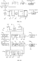
- the first reagent position 211a and the second reagent position 211b are arranged in parallel according to a preset direction, and at least the first electromagnetic field shielding circuit 25a and/or the second electromagnetic field shielding circuit 25b is provided between the first reagent position 211a and the second reagent position 211b, and preferably the first electromagnetic field shielding circuit 25a and the second electromagnetic field shielding circuit 25b are a same electromagnetic field shielding circuit, as shown in FIG. 5A .
- first reagent position 211a and the second reagent position 211b are arranged in parallel according to a preset direction, and the first electromagnetic field shielding circuit 25a is provided on one side of the first reagent position 211a opposite to the second reagent position 211b, and/or the second electromagnetic field shielding circuit 25b is provided on one side of the second reagent position 211b opposite to the first reagent position 211a, as shown in FIG. 5B .
- the first reagent position 211a and the second reagent position 211b are arranged in parallel according to a preset direction, and the first electromagnetic field shielding circuit 25a and/or the second electromagnetic field shielding circuit 25b is provided between the first reagent position 211a and the second reagent position 211b, and the first electromagnetic field shielding circuit 25a is provided on one side of the first reagent position 211a opposite to the second reagent position 211b, and/or the second electromagnetic field shielding circuit 25b is provided on one side of the second reagent position 211b opposite to the first reagent position 211a, as shown in FIG. 5C .
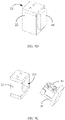
- the reagent placement compartment 21 includes a compartment body 22 and a reagent placement assembly 24 slidably disposed corresponding to the compartment body 22.
- the reagent placement assembly 24 is provided with at least two reagent positions 211 arranged in parallel according to a preset direction, wherein one side of one reagent position 211 and the other opposite side of another reagent position 211 are provided with electromagnetic field shielding circuits 25, or two opposite sides of each reagent position 211 are provided with electromagnetic field shielding circuits 25, or an electromagnetic field shielding circuit 25 is disposed between two adjacent reagent positions 211, to implement electromagnetic shielding for reagent information of a reagent container 50 placed in a non-target reagent position by means of the electromagnetic field shielding circuit 25.
- the first electromagnetic field shielding circuit 25a is provided on one side of the first reagent position 211a
- the second electromagnetic field shielding circuit 25b is provided on one side of the second reagent position 211b.
- both sides of the first reagent position 211a are provided with the first electromagnetic field shielding circuit 25a.
- at least one of the first electromagnetic field shielding circuit 25a and the second electromagnetic field shielding circuit 25b is provided between the first reagent position 211a and the second reagent position 211b.
- the compartment body 22 is formed with an accommodating cavity 221 having an opening; the reagent placement assembly 24 is in a slidable fit with the compartment body 22, and can enter or leave the accommodating cavity 221 through the opening, so as to be at least partially accommodated in the accommodating cavity 221 and cover the opening of the accommodating cavity 221, thereby storing reagent containers 50 placed in the reagent positions 211.
- the signal transmission circuit 26 is disposed corresponding to the reagent positions 211 and is connected to the information read/write device 23 and the antenna module 28, so as to transmit the emission electromagnetic field to the information storage component 501 in the corresponding reagent position 211, so that the information read/write device 23 can read reagent information stored in the reagent container 50 placed in the corresponding reagent position 211.
- the reagent placement assembly 24 includes a bracket 241 and a compartment door module 243 connected to the bracket 241.
- the at least two reagent positions 211 are formed in the bracket 241.
- the signal transmission circuit 26 is fixed on the compartment door module 243, and is disposed corresponding to the reagent positions 211. Under the action of an external force, the bracket 241 can enter or leave the accommodating cavity 221 through the opening of the accommodating cavity 221, and can cover the opening of the accommodating cavity 221 by means of the door module 243.
- the signal transmission circuit 26 may be disposed corresponding to the reagent positions 211 in the following manners: One reagent position 211 is disposed corresponding to at least two signal transmission circuits 26, or one signal transmission circuit 26 is disposed corresponding to at least two reagent positions 211, or one reagent position 211 is disposed corresponding to one signal transmission circuit 26.
- the signal transmission circuits 26 and the reagent positions 211 are disposed in a one-to-one correspondence, and the parallel arrangement direction of the signal transmission circuits 26 is the same as that of the reagent positions 211, so that each signal transmission circuit 26 can better read reagent information of the reagent container 50 placed in the preset reagent position 211.
- At least two first signal transmission circuits 26a are provided corresponding to the first reagent position 211a, and at least two second signal transmission circuits 26b are provided corresponding to the second reagent position 211b.
- at least one of the first signal transmission circuit 26a and the second signal transmission circuit 26b is provided corresponding to both the first reagent position 211a and the second reagent position 211b (e.g., the first signal transmission circuit 26a and the second signal transmission circuit 26b are a same signal transmission circuit).
- the first signal transmission circuit 26a is provided corresponding to the first reagent position 211a
- the second signal transmission circuit 26b is provided corresponding to the second reagent position 211b (i.e., the first signal transmission circuit 26a and the second signal transmission circuit 26b are independent of each other).
- the signal transmission circuit 26 may alternatively be disposed in the bracket 241 or in the compartment body 22, as long as the information read/write device 23 can interact with the information storage component 501 of the reagent container 50 placed in the target reagent position to obtain the corresponding reagent information.
- the signal transmission circuit 26 corresponding to the non-target reagent position may be used as the electromagnetic field shielding circuit.
- the first information read/write device 23a transmits the first electromagnetic field by means of the first signal transmission circuit 26a and the first antenna module 28a to the reagent container 50 in the first reagent position 211a, to perform signal interaction with the information storage component 501 of the reagent container 50 in the first reagent position 211a, so as to read reagent information stored in the information storage component 501 of the reagent container 50 in the first reagent position 211a.
- the second reagent position 211b is the non-target reagent position
- the second signal transmission circuit 26b is connected to the second antenna module 28b to generate the second counter electromagnetic field, so as to weaken the first electromagnetic field transmitted by the first information read/write device 23a via the first signal transmission circuit 26a and the first antenna module 28a to the second reagent position 211b, so that the information storage component 501 of the reagent container 50 in the second reagent position 211b cannot establish a communication connection with the first information read/write device 23a, thereby ensuring that the first information read/write device 23a can accurately read the reagent information in the information storage component 501 placed in the target reagent position.
- the second information read/write device 23b transmits the second electromagnetic field by means of the second signal transmission circuit 26b and the second antenna module 28b to the reagent container 50 in the second reagent position 211b, to perform signal interaction with the information storage component 501 of the reagent container 50 in the second reagent position 211b, so as to read reagent information stored in the information storage component 501 of the reagent container 50 in the second reagent position 211b.
- the first reagent position 211a is the non-target reagent position
- the first signal transmission circuit 26a is connected to the first antenna module 28a to generate the first counter electromagnetic field, so as to weaken the second electromagnetic field transmitted by the second information read/write device 23b via the second signal transmission circuit 26b and the second antenna module 28b to the first reagent position 211a, so that the information storage component 501 of the reagent container 50 in the first reagent position 211a cannot establish a communication connection with the second information read/write device 23b, thereby ensuring that the second information read/write device 23b can accurately read the reagent information in the information storage component 501 placed in the target reagent position.
- the electromagnetic field shielding circuit 25 and the signal transmission circuit 26 are independent of each other, and the electromagnetic field shielding circuit 25 include a third antenna module.
- the electromagnetic field shielding circuit 25 may generate a counter electromagnetic field by means of the third antenna module, to weaken the electromagnetic field transmitted to the non-target reagent position.
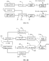
- the signal transmission circuit 26 includes a first signal transmission circuit 26a and a second signal transmission circuit 26a independent of each other, and the electromagnetic field shielding circuit 25, the first signal transmission circuit 26a and the second signal transmission circuit 26a are independent of each other, as shown in FIG. 6 .
- the electromagnetic field shielding circuit 25 and the signal transmission circuit 26 being independent of each other may be realized by the following ways: the electromagnetic field shielding circuit 25 include a first electromagnetic field shielding circuit 25a and a second electromagnetic field shielding circuit 25b independent of each other, and each of the first electromagnetic field shielding circuit 25a and the second electromagnetic field shielding circuit 25b includes a third antenna module, and the signal transmission circuit 26, first electromagnetic field shielding circuit 25a and the second electromagnetic field shielding circuit 25b are independent of each other; or the electromagnetic field shielding circuit 25 include a first electromagnetic field shielding circuit 25a and a second electromagnetic field shielding circuit 25b independent of each other, and each of the first electromagnetic field shielding circuit 25a and the second electromagnetic field shielding circuit 25b includes a third antenna module, the signal transmission circuit 26 includes a first signal transmission circuit 26a and a second signal transmission circuit 26a, wherein the first signal transmission circuit 26a, the second signal transmission circuit 26b, first electromagnetic field shielding circuit 25a and the second electromagnetic field shielding circuit 25b are independent of each other.
- the information read/write device 23 includes several sub-information read/write devices 231 disposed corresponding to the reagent positions 211, and each sub-information read/write device 231 is electrically connected to the corresponding signal transmission circuit 26, so as to read or write information from or to the information storage component 501 in the corresponding reagent container 50 by means of the corresponding signal transmission circuit 26 and the antenna module 28. That is, as mentioned above in combination with FIG.
- the first antenna module 28a, the first signal transmission circuit 26a, the first information read/write device 23a (i.e., a sub-information read/write device 231) and the first electromagnetic field shielding circuit 25a correspond to the first reagent position 211a
- the second antenna module 28b, the second signal transmission circuit 26b, the second information read/write device 23b (i.e., a sub-information read/write device 231) and the second electromagnetic field shielding circuit 25b correspond to the second reagent position 211b.
- each signal transmission circuit 26 disposed corresponding to the reagent position 211 includes a first matching circuit 261, and each antenna module 28 is provided with a first antenna 281 corresponding to the reagent position 211.
- a connection relationship between the sub-information read/write device 231, the first matching circuit 261, and the first antenna 281 corresponding to the reagent position 211 is that : each corresponding sub-information read/write device 231 is electrically connected to the first matching circuit 261, and the first matching circuit 261 is electrically connected to the first antenna 281, so as to read or write information from or to the information storage component 501 in the corresponding reagent position 211 by means of the first matching circuit 261 and the first antenna 281.
- the first antenna 281 is driven by the first matching circuit 261 to generate a corresponding electromagnetic field, and the interaction with the corresponding information storage component 501 is performed by using the electromagnetic field, so as to read or write information from or to the information storage component 501.
- a parameter, such as an electric field strength or an electric field direction, of the electric field emitted by the first antenna 281 can be adjusted by adjusting a circuit parameter of the first matching circuit 261 or a driving parameter of the sub-information read/write device 231.
- each signal transmission circuit includes a first matching circuit 261, and each antenna module is provided with a first antenna 281, that is, the first signal transmission circuit 26a and the second signal transmission circuit 26b respectively include a first matching circuit 261, and the first antenna module 28a and the second antenna module 28b respectively include a first antenna 281.
- the first information read/write device 23a is connected to the first matching circuit 261 of the first signal transmission circuit 26a, and the first matching circuit 261 of the first signal transmission circuit 26a is capable of being connected to the first antenna 281 of the first antenna module 28a, so as to perform signal interaction with the information storage component of the reagent container in the first reagent position 211a by means of the first matching circuit 261 of the first signal transmission circuit 26a and the first antenna 281 of the first antenna module 28a, to read or write information from or to the information storage component 501 of the reagent container 50 in the first reagent position 211a, and obtain reagent information stored in the information storage component 501 when reading information.
- the second information read/write device 23b is connected to the first matching circuit 261 of the second signal transmission circuit 26b, and the first matching circuit 261 of the second signal transmission circuit 26b is capable of being connected to the first antenna 281 of the second antenna module 28b, so as to perform signal interaction with the information storage component of the reagent container in the second reagent position 211b by means of the first matching circuit 261 of the second signal transmission circuit 26a and the first antenna 281 of the second antenna module 28a, to read or write information from or to the information storage component 501 of the reagent container 50 in the second reagent position 211b, and obtain reagent information stored in the information storage component 501 when reading information.
- a parameter, such as an electric field strength or an electric field direction, of the electric field emitted by the first antenna 281 of the first antenna module 28a can be adjusted by adjusting a circuit parameter of the first matching circuit 261 of the first antenna module 28a or a driving parameter of the first information read/write device 23a.
- a parameter, such as an electric field strength or an electric field direction, of the electric field emitted by the first antenna 281 of the second antenna module 28b can be adjusted by adjusting a circuit parameter of the first matching circuit 261 of the second antenna module 28b or a driving parameter of the second information read/write device 23b.
- a method by which the controller 27 controls the electromagnetic field shielding circuit 25 to generate a counter electromagnetic field, so as to weaken an electromagnetic field emitted and transmitted by the signal transmission circuit 26 and the antenna module 28 corresponding to the target reagent position to another reagent position may be as follows: the electromagnetic field shielding circuit 25 is provided with a shielding loop 251; and when the information read/write device 23 transmits the emission electromagnetic field by means of the signal transmission circuit 26 and the antenna module 28 corresponding to the target reagent position, the controller 27 controls a current of the shielding loop 251 adjacent to the target reagent position to be greater than a preset current value, and a direction of the current to be opposite to that of a current of the signal transmission circuit 26 corresponding to the target reagent position.
- a method of controlling the current of the shielding loop 251 may be as follows: the reagent supply device 20 is provided with a shielding signal output component connected to the controller 27. A shielding signal output terminal of the shielding signal output component is electrically connected to the shielding loop 251; and when the information read/write device 23 transmits the emission electromagnetic field by means of the signal transmission circuit 26 and the antenna module 28 corresponding to the target reagent position, the controller 27 controls the shielding signal output component to output a shielding signal, so that the current of the shielding loop 251 is greater than the preset current value, and the direction of the current is opposite to that of the current of the signal transmission circuit 26 corresponding to the target reagent position, so that the counter electromagnetic field generated by the shielding loop 251 in cooperation with the antenna module 28 can effectively weaken the electromagnetic field transmitted from the emission electromagnetic field to the another reagent position.
- the shielding signal output component may be a signal output element disposed independently of the sub-information read/write device 231, or may be the sub-information read/write device 231 corresponding to a non-target reagent position, which is temporarily used as a shielding signal output component when the sub-information read/write device 231 corresponding to the target reagent position transmits the emission electromagnetic field by means of the corresponding signal transmission circuit 26 and antenna module 28.
- the sub-information read/write device 231 corresponding to the reagent position 211 is taken as an example of the shielding signal output component for description, but the shielding signal output component is not necessarily the corresponding sub-information read/write device 231.
- the sub-information read/write device 231 corresponding to the reagent position 211 is further configured to output a shielding signal to adjust the current of the shielding loop 251, the shielding loop 251 corresponds to the reagent position 211, and a shielding signal output terminal of the sub-information read/write device 231 is electrically connected to the shielding loop 251; and when the information read/write device 23 transmits the emission electromagnetic field by means of the signal transmission circuit 26 and the antenna module 28 corresponding to the target reagent position, that is, when the sub-information read/write device 231 disposed corresponding to the target reagent position transmits the emission electromagnetic field by means of the signal transmission circuit 26 and the antenna module 28 corresponding to the target reagent position, the controller 27 controls the sub-information read/write device 231 adjacent to the target reagent position to output a shielding signal, so that the current of the shielding loop 251 adjacent to the target reagent position is greater than the preset current value, and the direction of the current is opposite to that of the current
- the emission electromagnetic field can activate the information storage component 501 placed in the target reagent position, to read the reagent information stored in the information storage component 501 in the target reagent position, and the emission electromagnetic field transmitted to the another reagent position adjacent to the target reagent position is not enough to interact with the information storage component 501 in the another reagent position, thereby ensuring that the information read/write device 23 can accurately read the reagent information in the corresponding information storage component 501 placed in the target reagent position.
- each electromagnetic field shielding circuit includes a shielding loop 251, that is, each of the first electromagnetic field shielding circuit 25a and the second electromagnetic field shielding circuit 25b includes a shielding loop 251.
- a method by which the controller 27 controls the electromagnetic field shielding circuit 25 to generate a counter electromagnetic field, so as to weaken an electromagnetic field emitted and transmitted by the signal transmission circuit 26 and the antenna module 28 corresponding to the target reagent position to another reagent position may be as follows:
- the shielding loop 251 of the first electromagnetic field shielding circuit 25a or the second electromagnetic field shielding circuit 25b may be controlled as follows: a shielding signal is outputted to the shielding loop 251 of the corresponding electromagnetic field shielding circuit by a shielding signal output component, to actively control the value of the current of the shielding loop 251 by adjusting a signal strength of the shielding signal.
- the information read/write device 23 corresponding to the non-target reagent position is used as the shielding signal output component, that is, when the first reagent position 211a is the target reagent position, the second information read/write device 23b may be used as the shielding signal output component; when the second reagent position 211b is the target reagent position, the first information read/write device 23a may be used as the shielding signal output component.
- each information read/write device is further configured to output a shielding signal to adjust the current of the corresponding shielding loop, and a shielding signal output terminal of each formation read/write device is electrically connected to the corresponding shielding loop. That is, the first information read/write device 23a is connected to the shielding loop 251 of the first electromagnetic field shielding circuit 25a, to adjust the current of the shielding loop 251 of the first electromagnetic field shielding circuit 25a, and the second information read/write device 23b is connected to the shielding loop 251 of the second electromagnetic field shielding circuit 25b, to adjust the current of the shielding loop 251 of the second electromagnetic field shielding circuit 25b.
- the controller 27 is further configured to control the second information read/write device 23b to output a shielding signal, so that the current of the shielding loop 251 of the second electromagnetic field shielding circuit 25b is greater than the preset current value, and the
- the controller 27 is further configured to control the first information read/write device 23a to output a shielding signal, so that the current of the shielding loop 251 of the first electromagnetic field shielding circuit 25a is greater than the preset current value, and the direction of said current is opposite to that of the current of the second signal transmission circuit 26b, so that the first counter electromagnetic field generated by the shielding loop 251 of the first electromagnetic field shielding circuit 25a in cooperation with the first antenna module 28a can effectively weaken the electromagnetic field transmitted from the second electromagnetic field to the first reagent position 211a.
- the first antenna 281 of the antenna module 28 corresponding to the reagent position 211 is further configured to transmit the counter electromagnetic field, and when the information read/write device 23 transmits the emission electromagnetic field by means of the signal transmission circuit 26 and the antenna module 28 corresponding to the target reagent position, the controller 27 controls the first antenna 281 of the antenna module 28 adjacent to the target reagent position to emit the counter electromagnetic field.
- the controller 27 controls the corresponding shielding signal output component to output the shielding signal, that is, controls the sub-information read/write device 231 adjacent to the target reagent position to output the shielding signal.
- the sub-information read/write device 231 generates and emits the counter electromagnetic field by means of the corresponding shielding loop 251 and first antenna 281, so as to weaken the electromagnetic field diffused from the emission electromagnetic field to the another reagent position adjacent to the target reagent position.
- the shielding signal that is output by the sub-information read/write device 231 makes the current of the shielding loop 251 adjacent to the target reagent position greater than the preset current value, and the direction of the current opposite to that of the current of the signal transmission circuit 26 corresponding to the target reagent position.
- each reagent position 211 is correspondingly provided with a first antenna 281, and each first antenna 281 has at least two working modes.
- the two working modes include a first working mode for cooperating with the signal transmission circuit 261 to output the emission electromagnetic field, and a second working mode for cooperating with the signal shielding loop 251 to output the counter electromagnetic field, wherein switching between the first working mode and the second working mode is determined according to the corresponding target reagent position.
- the controller 27 controls the information read/write device 23 to transmit the emission electromagnetic field by means of the signal transmission circuit 26 and the first antenna 281 corresponding to the target reagent position, so as to interact with the information storage component 501 of the reagent container 50 in the target reagent position to obtain the corresponding reagent information.
- the controller 27 controls the sub-information read/write device 231 corresponding to the reagent position 211 adjacent to the target reagent position to cooperate with the corresponding shielding loop 251 and the first antenna 281 to generate the counter electromagnetic field, so as to weaken the emission electromagnetic field transmitted from the first antenna 281 corresponding to the target reagent position to the adjacent reagent position, so that the emission electromagnetic field transmitted from the first antenna 281 disposed corresponding to the target reagent position is not enough to activate the information storage component 501 in the another reagent position and establish a communication connection with the information storage component 501 in the another reagent position for interaction, thereby ensuring that the sub-information read/write device 231 disposed corresponding to the target reagent position can interact only with the information storage component 501 in the target reagent position to obtain the reagent information corresponding to the reagent container 50 placed in the corresponding target reagent position.
- the sub-information read/write device 231 disposed corresponding to the target reagent position when the sub-information read/write device 231 disposed corresponding to the target reagent position performs signal interaction with the information storage component 501 of the reagent container 50 placed in the target reagent position, the sub-information read/write device 231 corresponding to the non-target reagent position adjacent to the target reagent position may temporarily serve as a shielding signal output component, and outputs the counter electromagnetic field by means of the corresponding shielding loop 251 and the first antenna 281 corresponding to the non-target reagent position adjacent to the target reagent position.
- each first antenna is further configured to transmit the counter electromagnetic field, that is, the first antenna 281 of the first antenna module 28a and the first antenna 281 of the second antenna module 28b are further configured to transmit the corresponding counter electromagnetic field.
- the first electromagnetic field shielding circuit 25a is capable of being connected to the first antenna 281 of the first antenna module 28a to generate the first counter electromagnetic field
- the second electromagnetic field shielding circuit 25b is capable of being connected to the first antenna 281 of the second antenna module 28b to generate the second counter electromagnetic field.
- the controller 27 is further configured to control the second electromagnetic field shielding circuit 25b to be connected to the first antenna 281 of the second antenna module 28b to generate the second counter electromagnetic field; or when the second information read/write device 23b transmits the second electromagnetic field by means of the second signal transmission circuit 26b and the second antenna module 28b, the controller 27 is further configured to control the first electromagnetic field shielding circuit 25a to be connected to the first antenna 281 of the first antenna module 28a to generate the first counter electromagnetic field.
- the controller 27 is further configured to control the second information read/write device 23b to output a shielding signal, so that the second information read/write device 23b generates and emits the second counter electromagnetic field by means of the shielding loop 251 of the second electromagnetic field shielding circuit 25b and the first antenna 281 of the second antenna module 28b, so as to weaken the electromagnetic field diffused from the first electromagnetic field to the non-target reagent position (for example the second reagent position 211b).
- the controller 27 is further configured to control the first information read/write device 23a to output a shielding signal, so that the first information read/write device 23a generates and emits the first counter electromagnetic field by means of the shielding loop 251 of the first electromagnetic field shielding circuit 25a and the first antenna 281 of the first antenna module 28a, so as to weaken the electromagnetic field diffused from the second electromagnetic field to the non-target reagent position (for example the first reagent position 211a).
- the shielding loop 251 includes a second matching circuit 2511 and a switch module 2512, wherein an impedance of the second matching circuit 2511 is less than that of the first matching circuit 261.
- a method by which the controller 27 controls the current of the shielding loop 251 adjacent to the target reagent position to be greater than the preset current value, and the direction of the current to be opposite to that of the current of the signal transmission circuit 26 corresponding to the target reagent position may be as follows: when the information read/write device 23 transmits the emission electromagnetic field by means of the signal transmission circuit 26 and the antenna module 28 corresponding to the target reagent position, the controller 27 controls a switch module 252 adjacent to the target reagent position to electrically connect the second matching circuit 251 to the antenna module 28, and the second matching circuit 2511 and the antenna module 28 form a closed loop, so that an impedance of the shielding loop 251 adjacent to the target reagent position is less than that of the signal transmission circuit 26 corresponding to the target reagent position.
- the second matching circuit 2511 and the antenna module 28 form a closed loop, when the closed loop receives the emission electromagnetic field emitted and transmitted to the another reagent position by the information read/write device 23 corresponding to the target reagent position via the signal transmission circuit 26 and the antenna module 28, since the antenna module 28 adjacent to the target reagent position is in the emission electromagnetic field generated by the signal transmission circuit 26, and the impedance of the shielding loop 251 adjacent to the target reagent position is less than that of the signal transmission circuit 26 corresponding to the target reagent position, it can be known from Lenz's law that the antenna module 28 in the emission electromagnetic field and adjacent to the target reagent position can generate an induced current with a current value greater than the preset current value and a current direction opposite to that of the current of the signal transmission circuit 26 corresponding to the target reagent position, and the induced current generates a counter electromagnetic field with a direction opposite to that of the emission electromagnetic field, so as to weaken the emission electromagnetic
- each electromagnetic field shielding circuit includes a shielding loop 251, and each shielding loop 251 includes a second matching circuit 2511 and a switch module 2512, wherein an impedance of the second matching circuit 2511 is less than that of the first matching circuit 261.
- each shielding loop 251 of the first electromagnetic field shielding circuit 25a and the second electromagnetic field shielding circuit 25b includes a second matching circuit 2511 and a switch module 2512, wherein an impedance of the second matching circuit 2511 of the first electromagnetic field shielding circuit 25a is less than that of the first matching circuit 261 of the first signal transmission circuit 26a, and an impedance of the second matching circuit 2511 of the second electromagnetic field shielding circuit 25b is less than that of the first matching circuit 261 of the second signal transmission circuit 26b.
- the controller 27 is further configured to control the switch module 2512 of the shielding loop 251 of the second electromagnetic field shielding circuit 25b to connect the second matching circuit 2511 of the shielding loop 251 of the second electromagnetic field shielding circuit 25b to the second antenna module 28b, so that the second matching circuit 2511 of the shielding loop 251 of the second electromagnetic field shielding circuit 25b and the second antenna module 28b form a closed loop, wherein an impedance of the shielding loop 251 of the second electromagnetic field shielding circuit 25b is less than that of the first signal transmission circuit 26a.
- the second matching circuit 2511 of the second electromagnetic field shielding circuit 25b and the second antenna module 28b form a closed loop
- the closed loop receives the first electromagnetic field emitted and transmitted to the another reagent position (for example the second reagent position 211b) by the first information read/write device 23a corresponding to the target reagent position via the first signal transmission circuit 26a and the first antenna module 28a
- the second antenna module 28b adjacent to the target reagent position is in the first electromagnetic field generated by the first signal transmission circuit 26a
- the impedance of the shielding loop 251 of the second electromagnetic field shielding circuit 25b adjacent to the target reagent position is less than that of the first signal transmission circuit 26a corresponding to the target reagent position
- Lenz's law that the second antenna module 28b in the first electromagnetic field and adjacent to the target reagent position can generate an induced current with a current value greater than the preset current value and a current direction opposite to that of the current of the first signal transmission circuit 26a corresponding to
- the controller 27 is further configured to control the switch module 2512 of the shielding loop 251 of the first electromagnetic field shielding circuit 25a to connect the second matching circuit 2511 of the shielding loop 251 of the first electromagnetic field shielding circuit 25a to the first antenna module 28a, so that the second matching circuit 2511 of the shielding loop 251 of the first electromagnetic field shielding circuit 25a and the first antenna module 28a form a closed loop, wherein an impedance of the shielding loop 251 of the first electromagnetic field shielding circuit 25a is less than that of the second signal transmission circuit 26b.
- the second matching circuit 2511 of the first electromagnetic field shielding circuit 25a and the first antenna module 28a form a closed loop
- the closed loop receives the second electromagnetic field emitted and transmitted to the another reagent position (for example the first reagent position 211a) by the second information read/write device 23b corresponding to the target reagent position via the second signal transmission circuit 26b and the second antenna module 28b
- the first antenna module 28a adjacent to the target reagent position is in the second electromagnetic field generated by the second signal transmission circuit 26b
- the impedance of the shielding loop 251 of the first electromagnetic field shielding circuit 25a adjacent to the target reagent position is less than that of the second signal transmission circuit 26b corresponding to the target reagent position
- Lenz's law that the first antenna module 28a in the second electromagnetic field and adjacent to the target reagent position can generate an induced current with a current value greater than the preset current value and a current direction opposite to that of the current of the second signal transmission circuit 26b corresponding to
- this implementation differs from the implementation corresponding to FIG. 9A in that the shielding loop 251 further includes the first matching circuit 261.
- the shielding loop 251 includes the second matching circuit 2511, the first matching circuit 261, and the switch module 2512, where the impedance of the second matching circuit 2511 is less than that of the first matching circuit 261.
- the controller 27 controls the switch module 252 adjacent to the target reagent position to electrically connect the second matching circuit 251 to the antenna module 28, and the second matching circuit 2511 and the antenna module 28 form a closed loop, so that an impedance of the shielding loop 251 adjacent to the target reagent position is less than that of the signal transmission circuit 26 corresponding to the target reagent position.
- the shielding loop 251 includes a second matching circuit 2511 and a switch module 2512, and each sub-information read/write device 231 is further configured to output a shielding signal.
- a method by which the controller 27 controls the current of the shielding loop 251 adjacent to the target reagent position to be greater than the preset current value, and the direction of the current to be opposite to that of the current of the signal transmission circuit 26 corresponding to the target reagent position may be as follows: when the information read/write device 23 transmits the emission electromagnetic field by means of the signal transmission circuit 26 and the antenna module 28 corresponding to the target reagent position, the controller 27 controls the switch module 2512 adjacent to the target reagent position to electrically connect the second matching circuit 2511 to the antenna module 28, and controls the switch module 2512 to electrically connect the second matching circuit 2511 to the sub-information read/write device 231; and the controller 27 further controls the sub-information read/write device 231 to output a shielding signal.
- the controller 27 controls the switch module 2512 adjacent to the target reagent position to electrically connect the second matching circuit 2511 to the antenna module 28, and controls the switch module 2512 to electrically connect the second matching circuit 2511 to the sub-information read/write device 231; and the controller 27 further controls the sub-information read/write device 231 to output a shielding signal, so that the current of the shielding loop 251 adjacent to the target reagent position is greater than the preset current value, and the direction of the current is opposite to that of the current of the signal transmission circuit 26 corresponding to the target reagent position, such that the counter electromagnetic field generated by the
- each electromagnetic field shielding circuit includes a shielding loop 251, and each shielding loop 251 includes a second matching circuit 2511 and a switch module 2512, and each of the first information read/write device 23a and the second information read/write device 23b is further configured to output a shielding signal.
- the controller 27 is further configured to control the switch module 2512 of the shielding loop 251 of the second electromagnetic field shielding circuit 25b to connect the second matching circuit 2511 of the shielding loop 251 of the second electromagnetic field shielding circuit 25b to the second antenna module 28b, control the switch module 2512 of the shielding loop 251 of the second electromagnetic field shielding circuit 25b to connect the second matching circuit 2511 of the shielding loop 521 of the second electromagnetic field shielding circuit 25b to the second information read/write device 23b, and control the second information read/write device 23b to output a shielding signal to the second electromagnetic field shielding circuit 25b, so that for example the current of the shielding loop 251 of the second electromagnetic field shielding circuit 25b is greater than the preset current value, and the direction of said current is opposite to that of the current of the first signal
- the second counter electromagnetic field generated by the shielding loop 251 of the second electromagnetic field shielding circuit 25b and the second antenna module 28b is sufficient to weaken the first electromagnetic field emitted and transmitted to the second reagent position 211b by the first information read/write device 23a via the first signal transmission circuit 26a and the first antenna module 28a.
- the controller 27 is further configured to control the switch module 2512 of the shielding loop 251 of the first electromagnetic field shielding circuit 25a to connect the second matching circuit 2511 of the shielding loop 251 of the first electromagnetic field shielding circuit 25a to the first antenna module 28a, control the switch module 2512 of the shielding loop 251 of the first electromagnetic field shielding circuit 25a to connect the second matching circuit 2511 of the shielding loop 251 of the first electromagnetic field shielding circuit 25a to the first information read/write device 23a, and control the first information read/write device 23a to output a shielding signal to the first electromagnetic field shielding circuit 25a, so that for example the current of the shielding loop 251 of the first electromagnetic field shielding circuit 25a is greater than the preset current value, and the direction of said current is opposite to that of the current of the second signal
- the first counter electromagnetic field generated by the shielding loop 251 of the first electromagnetic field shielding circuit 25a and the second antenna module 28a is sufficient to weaken the second electromagnetic field emitted and transmitted to the first reagent position 211a by the second information read/write device 23b via the second signal transmission circuit 26b and the second antenna module 28b.
- this implementation differs from the implementation provided in FIG. 11A in that the shielding loop 251 further includes the first matching circuit 261, and each sub-information read/write device 231 is further configured to output a shielding signal.
- the shielding loop 251 includes the second matching circuit 2511, the first matching circuit 261, and the switch module 2512, wherein the impedance of the second matching circuit 2511 is less than that of the first matching circuit 261.
- the controller 27 controls the switch module 2512 adjacent to the target reagent position to electrically connect the second matching circuit 2511 to the antenna module 28, and controls the switch module 2512 to electrically connect the second matching circuit 2511 to the sub-information read/write device 231; and the controller 27 further controls the sub-information read/write device 231 to output a shielding signal.
- the shielding loop includes a switch module 2512.
- a method by which the controller 27 controls the current of the shielding loop 251 adjacent to the target reagent position to be greater than the preset current value, and the direction of the current to be opposite to that of the current of the signal transmission circuit 26 corresponding to the target reagent position may be as follows: when the information read/write device 23 transmits the emission electromagnetic field by means of the signal transmission circuit 26 and the antenna module 28 corresponding to the target reagent position, the controller 27 controls the switch module 2512 adjacent to the target reagent position to be closed, so that the switch module 2512 and the antenna module 28 form a closed loop, so that an impedance of the shielding loop 251 adjacent to the target reagent position is less than that of the signal transmission circuit 26 corresponding to the target reagent position.
- the switch module 2512 and the antenna module 28 form a closed loop, when the closed loop receives the emission electromagnetic field emitted and transmitted to the another reagent position by the information read/write device 23 corresponding to the target reagent position via the signal transmission circuit 26 and the antenna module 28, since the antenna module 28 adjacent to the target reagent position is in the electromagnetic field generated by the signal transmission circuit 26, and the impedance of the shielding loop 251 adjacent to the target reagent position is less than that of the signal transmission circuit 26 corresponding to the target reagent position, it can be known from Lenz's law that the antenna module 28 in the emission electromagnetic field and adjacent to the target reagent position can generate an induced current with a current value greater than the preset current value and a current direction opposite to that of the current of the signal transmission circuit 26 corresponding to the target reagent position, and the induced current generates a counter electromagnetic field with a direction opposite to that of the emission electromagnetic field, so as to weaken the emission electromagnetic field
- each electromagnetic field shielding circuit includes a shielding loop 251, and each shielding loop 251 includes a switch module 2512. That is, each shielding loop 251 of the first electromagnetic field shielding circuit 25a and the second electromagnetic field shielding circuit 25b includes a switch module 2512.
- the controller 27 is further configured to control the switch module 2512 of the shielding loop 251 of the second electromagnetic field shielding circuit 25a to be closed, so that the switch module 2512 of the shielding loop 251 of the second electromagnetic field shielding circuit 25b and the second antenna module 28b form a closed loop, wherein an impedance of the shielding loop 251 of the second electromagnetic field shielding circuit 25a is less than that of the first signal transmission circuit 26a.
- the switch module 2512 of the shielding loop 251 of the second electromagnetic field shielding circuit 25b and the second antenna module 28b form a closed loop
- the closed loop receives the first electromagnetic field emitted and transmitted to the another reagent position (for example the second reagent position 211b) by the first information read/write device 23a corresponding to the target reagent position via the first signal transmission circuit 26a and the first antenna module 28a
- the second antenna module 28b adjacent to the target reagent position is in the first electromagnetic field generated by the first signal transmission circuit 26a
- the impedance of the shielding loop 251 of the second electromagnetic field shielding circuit 25b adjacent to the target reagent position is less than that of the first signal transmission circuit 26a corresponding to the target reagent position
- the controller 27 is further configured to control the switch module 2512 of the shielding loop 251 of the first electromagnetic field shielding circuit 25a to be closed, so that the switch module 2512 of the shielding loop 251 of the first electromagnetic field shielding circuit 25a and the first antenna module 28a form a closed loop, wherein an impedance of the shielding loop 251 of the first electromagnetic field shielding circuit 25a is less than that of the second signal transmission circuit 26b.
- the switch module 2512 of the shielding loop 251 of the first electromagnetic field shielding circuit 25a and the first antenna module 28a form a closed loop
- the closed loop receives the second electromagnetic field emitted and transmitted to the another reagent position (for example the first reagent position 211a) by the second information read/write device 23b corresponding to the target reagent position via the second signal transmission circuit 26b and the second antenna module 28b
- the first antenna module 28a adjacent to the target reagent position is in the second electromagnetic field generated by the second signal transmission circuit 26b
- the impedance of the shielding loop 251 of the first electromagnetic field shielding circuit 25a adjacent to the target reagent position is less than that of the second signal transmission circuit 26b corresponding to the target reagent position
- the antenna module 28 includes a first antenna 281 and a second antenna 282, and the shielding loop 251 includes a switch module 2512, wherein an impedance value of the first antenna 281 is less than that of the second antenna 282, and each sub-information read/write device 231 is further configured to output a shielding signal.
- a method by which the controller 27 controls the current of the shielding loop 251 adjacent to the target reagent position to be greater than the preset current value, and the direction of the current to be opposite to that of the current of the signal transmission circuit 26 corresponding to the target reagent position may be as follows: when the information read/write device 23 transmits the emission electromagnetic field by means of the signal transmission circuit 26 and the antenna module 28 corresponding to the target reagent position, the controller 27 controls the switch module 2512 adjacent to the target reagent position to connect the first antenna 281 and the sub-information read/write device 231, and controls the sub-information read/write device 231 to output a shielding signal, so that the current of the shielding loop 251 adjacent to the target reagent position is greater than the preset current value, and the direction of the current is opposite to that of the current of the signal transmission circuit 26 corresponding to the target reagent position, such that the counter electromagnetic field generated by the shielding loop 251 and the first antenna 281 is enough to weaken the emission electromagnetic field.
- each antenna module is further provided with a second antenna 282, and each second antenna 282 is configured to transmit the corresponding counter electromagnetic field.
- Each electromagnetic field shielding circuit includes a shielding loop 251, and each shielding loop 251 includes a switch module 2512.
- the first electromagnetic field shielding circuit 25a is capable of being connected to the second antenna 282 of the first antenna module 28a to generate the first counter electromagnetic field
- the second electromagnetic field shielding circuit 25b is capable of being connected to the second antenna 282of the second antenna module 28b to generate the second counter electromagnetic field.
- the controller 27 is further configured to control the second electromagnetic field shielding circuit 25b to be connected to the second antenna 282 of the second antenna module 28b to generate the second counter electromagnetic field; or when the second information read/write device 23b transmits the second electromagnetic field by means of the second signal transmission circuit 26b and the first antenna 281 of the second antenna module 28b, the controller 27 is further configured to control the first electromagnetic field shielding circuit 25a to be connected to the second antenna 282 of the first antenna module 28a to generate the first counter electromagnetic field.
- the controller 27 is further configured to control the second information read/write device 23b to output a shielding signal, and control the switch module 2512 to connect the shielding loop 251 of the second electromagnetic field shielding circuit 25b to the second antenna 282 of the second antenna module 28b, to drive the second electromagnetic field shielding circuit 25b and the second antenna 282 of the second antenna module 28b to generate the second counter electromagnetic field.
- the controller 27 is further configured to control the first information read/write device 23a to output a shielding signal, and control the switch module 2512 to connect the shielding loop 251 of the first electromagnetic field shielding circuit 25a to the second antenna 282 of the first antenna module 28a, to drive the first electromagnetic field shielding circuit 25a and the second antenna 282 of the first antenna module 28a to generate the first counter electromagnetic field.
- the antenna module 28 includes a first antenna 281 and a second antenna 282, and the shielding loop 251 includes a switch module 2512 and a second matching circuit 2511, wherein an impedance value of the first antenna 281 is less than that of the second antenna 282.
- each sub-information read/write device 231 is further configured to output a shielding signal
- a method by which the controller 27 controls the current of the shielding loop 251 adjacent to the target reagent position to be greater than the preset current value, and the direction of the current to be opposite to that of the current of the signal transmission circuit 26 corresponding to the target reagent position may be as follows: the controller 27 controls the switch module 2512 adjacent to the target reagent position to connect the first antenna 281 and the second matching circuit 2511, and controls the switch module 2512 to connect the second matching circuit 2511 and the sub-information read/write device 231; and at the same time, controls the sub-information read/write device 231 to output a shielding signal, so that the current of the shielding loop 251 adjacent to the target reagent position is greater than the preset current value, and the direction of the current is opposite to that of the current of the signal transmission circuit 26 corresponding to the target reagent position, such that the counter electromagnetic field generated by the shielding loop 251 and the first antenna 281 is enough to weaken the emission electromagnetic field.
- each antenna module is further provided with a second antenna 282, and each second antenna 282 is configured to transmit the corresponding counter electromagnetic field.
- Each electromagnetic field shielding circuit includes a shielding loop 251, and each shielding loop 251 includes a second matching circuit 2511 and a switch module 2512.
- the first electromagnetic field shielding circuit 25a is capable of being connected to the second antenna 282 of the first antenna module 28a to generate the first counter electromagnetic field
- the second electromagnetic field shielding circuit 25b is capable of being connected to the second antenna 282of the second antenna module 28b to generate the second counter electromagnetic field.
- the controller 27 is further configured to control the second matching circuit 2511 of the second electromagnetic field shielding circuit 25b to be connected to the second antenna 282 of the second antenna module 28b to generate the second counter electromagnetic field; or when the second information read/write device 23b transmits the second electromagnetic field by means of the first matching circuit 261 of the second signal transmission circuit 26b and the first antenna 281 of the second antenna module 28b, the controller 27 is further configured to control the second matching circuit 2511 of the first electromagnetic field shielding circuit 25a to be connected to the second antenna 282 of the first antenna module 28a to generate the first counter electromagnetic field.
- the controller 27 is further configured to control the second information read/write device 23b to output a shielding signal, and control the switch module 2512 to connect the second matching circuit 2511 of the shielding loop 251 of the second electromagnetic field shielding circuit 25b to the second antenna 282 of the second antenna module 28b, to drive the first matching circuit 2511 of the second electromagnetic field shielding circuit 25b and the second antenna 282 of the second antenna module 28b to generate the second counter electromagnetic field.
- the controller 27 is further configured to control the first information read/write device 23a to output a shielding signal, and control the switch module 2512 to connect the second matching circuit 2511 of the shielding loop 251 of the first electromagnetic field shielding circuit 25a to the second antenna 282 of the first antenna module 28a, to drive the second matching circuit 2511 of the first electromagnetic field shielding circuit 25a and the second antenna 282 of the first antenna module 28a to generate the first counter electromagnetic field.
- an embodiment of the disclosure provides a reagent information reading method.
- the reagent information reading method is applied to the foregoing reagent supply device or sample analyzer.
- the reagent information reading method being applied to a sample analyzer is taken as an example for description, the reagent information reading method includes steps S101 and S102.
- Step S101 controlling the information read/write device to transmit the emission electromagnetic field by means of the signal transmission circuit and the antenna module corresponding to a target reagent position, so that the signal transmission circuit corresponding to the target reagent position performs signal interaction with the information storage component in the target reagent position.
- the information read/write device When the information read/write device transmits the emission electromagnetic field by means of the signal transmission circuit and the antenna module corresponding to the target reagent position, or when a reagent testing instruction is received, the information read/write device is controlled to transmit the emission electromagnetic field by means of the signal transmission circuit and the antenna module corresponding to the target reagent position, so that the signal transmission circuit corresponding to the target reagent position performs signal interaction with an information storage component in the target reagent position, to obtain the reagent information stored in the information storage component.
- the reagent testing instruction may be generated by triggering a corresponding information input device disposed on the reagent supply device or the sample analyzer, and the information input device includes, but is not limited to, a button, a keyboard, a touch display screen.
- the reagent testing instruction may be periodically generated and sent to the controller by the reagent supply device or the sample analyzer, which is not limited herein.
- the information input device is used to deliver a corresponding reagent testing instruction to the reagent supply device.
- the controller controls the information read/write device to generate the emission electromagnetic field by means of the signal transmission circuit corresponding to the target reagent position, so that the signal transmission circuit corresponding to the target reagent position performs signal interaction with the information storage component in the target reagent position, so that the corresponding information read/write device obtains the reagent information stored in the information storage component.
- Step S102 controlling the electromagnetic field shielding circuit to generate a counter electromagnetic field, so as to weaken an electromagnetic field transmitted from the emission electromagnetic field to another reagent position.
- the controller When receiving the reagent testing instruction, the controller further controls the electromagnetic field shielding circuit to generate a counter electromagnetic field, so as to weaken the electromagnetic field emitted and transmitted to another reagent position by the signal transmission circuit corresponding to the target reagent position in cooperation with the antenna module.
- the controller when receiving the reagent testing instruction, the controller further controls the electromagnetic field shielding circuit to generate a counter electromagnetic field by means of the corresponding antenna module, so as to weaken the electromagnetic field emitted and transmitted to the another reagent position by the signal transmission circuit corresponding to the target reagent position in cooperation with the antenna module, so that the electromagnetic field emitted by the signal transmission circuit is not enough to activate the information storage component in the another reagent position, thereby ensuring that the signal transmission circuit corresponding to the target reagent can interact only with the information storage component in the target reagent position, and the corresponding information read/write device obtains the reagent information stored in the information storage component.
- step S101 includes: controlling the first information read/write device to transmit the first electromagnetic field by means of the first signal transmission circuit and the first antenna module to the information storage component of the reagent container in the first reagent position, so that the first information read/write device performs signal interaction with the information storage component of the reagent container in the first reagent position; and step S102 includes: controlling the second electromagnetic field shielding circuit to be connected to the second antenna module to generate the second counter electromagnetic field, so as to weaken an electromagnetic field transmitted from the first electromagnetic field to the second reagent position.
- step S101 includes: controlling the second information read/write device to transmit the second electromagnetic field by means of the second signal transmission circuit and the second antenna module to the information storage component of the reagent container in the second reagent position, so that the second information read/write device performs signal interaction with the information storage component of the reagent container in the second reagent position; and step S102 includes: controlling the first electromagnetic field shielding circuit to be connected to the first antenna module to generate the first counter electromagnetic field, so as to weaken an electromagnetic field transmitted from the second electromagnetic field to the first reagent position.
- step S101 and step S102 may be interchanged.
- controlling the electromagnetic field shielding circuit to generate a counter electromagnetic field, so as to weaken an electromagnetic field transmitted from the emission electromagnetic field to another reagent position specifically includes: adjusting a current of the electromagnetic field shielding circuit, so that a direction of the current of the electromagnetic field shielding circuit is opposite to that of a current of the signal transmission circuit corresponding to the target reagent position.
- controlling the second electromagnetic field shielding circuit to generate the second counter electromagnetic field, so as to weaken an electromagnetic field transmitted from the first electromagnetic field to the second reagent position comprises: adjusting a current of the second electromagnetic field shielding circuit, so that a direction of the current of the second electromagnetic field shielding circuit is opposite to that of a current of the first signal transmission circuit; or controlling the first electromagnetic field shielding circuit to generate the first counter electromagnetic field, so as to weaken an electromagnetic field transmitted from the second electromagnetic field to the first reagent position comprises: adjusting a current of the first electromagnetic field shielding circuit, so that a direction of the current of the first electromagnetic field shielding circuit is opposite to that of a current of the second signal transmission circuit.
- controlling the electromagnetic field shielding circuit to generate a counter electromagnetic field, so as to weaken an electromagnetic field transmitted from the emission electromagnetic field to another reagent position specifically includes: adjusting a current of the electromagnetic field shielding circuit, so that a direction of the current of the electromagnetic field shielding circuit is opposite to that of a current of the signal transmission circuit corresponding to the target reagent position, and the current of the electromagnetic field shielding circuit is greater than or equal to that of the signal transmission circuit corresponding to the target reagent position.
- controlling the second electromagnetic field shielding circuit to generate the second counter electromagnetic field, so as to weaken an electromagnetic field transmitted from the first electromagnetic field to the second reagent position comprises: adjusting a current of the second electromagnetic field shielding circuit, so that a direction of the current of the second electromagnetic field shielding circuit is opposite to that of a current of the first signal transmission circuit, and the current of the second electromagnetic field shielding circuit is greater than or equal to that of the first signal transmission circuit; or controlling the first electromagnetic field shielding circuit to generate the first counter electromagnetic field, so as to weaken an electromagnetic field transmitted from the second electromagnetic field to the first reagent position comprises: adjusting a current of the first electromagnetic field shielding circuit, so that a direction of the current of the first electromagnetic field shielding circuit is opposite to that of a current of the second signal transmission circuit, and the current of the first electromagnetic field shielding circuit is greater than or equal to that of the second signal transmission circuit.
Landscapes
- Life Sciences & Earth Sciences (AREA)
- Health & Medical Sciences (AREA)
- Engineering & Computer Science (AREA)
- Physics & Mathematics (AREA)
- Chemical & Material Sciences (AREA)
- Immunology (AREA)
- General Physics & Mathematics (AREA)
- Analytical Chemistry (AREA)
- Biochemistry (AREA)
- General Health & Medical Sciences (AREA)
- Pathology (AREA)
- Molecular Biology (AREA)
- Biomedical Technology (AREA)
- Urology & Nephrology (AREA)
- Hematology (AREA)
- Microbiology (AREA)
- Food Science & Technology (AREA)
- Biotechnology (AREA)
- Cell Biology (AREA)
- Medicinal Chemistry (AREA)
- Bioinformatics & Cheminformatics (AREA)
- Biophysics (AREA)
- Bioinformatics & Computational Biology (AREA)
- Proteomics, Peptides & Aminoacids (AREA)
- Chemical Kinetics & Catalysis (AREA)
- Plasma & Fusion (AREA)
- Computer Networks & Wireless Communication (AREA)
- General Engineering & Computer Science (AREA)
- Theoretical Computer Science (AREA)
- Automatic Analysis And Handling Materials Therefor (AREA)
Abstract
Description
- The disclosure relates to the technical field of medical instruments, and in particular to a sample analyzer, a reagent supply device and a reagent information reading method.
- Sample analyzers are widely used in clinical testing, and existing sample analyzers mainly include a glycated hemoglobin analyzer, a blood cell analyzer, a whole blood CRP analyzer, etc. During blood analysis, a chemical reagent is required to support analysis of a blood sample. When the chemical reagent is used up, a user needs to replace it with a new reagent to support a sample analyzer in continuing analysis. Generally, the chemical reagent used by the sample analyzer is stored in a reagent supply device of the sample analyzer. The reagent supply device reads an information label provided on a reagent container by means of a corresponding information read/write device, to obtain information about a reagent stored in the reagent container.
- However, when a plurality of reagent containers are placed in a same reagent supply device, a plurality of corresponding information labels may all be located in an electromagnetic field of a same information read/write device, resulting in a problem of adjacent channel crosstalk. Consequently, the information label on a corresponding reagent container cannot be accurately read, resulting in reagent information errors.
- A main objective of embodiments of the disclosure is to provide a sample analyzer, a reagent supply device and a reagent information reading method, which are intended to solve the problem of adjacent channel crosstalk that may occur when a plurality of reagent containers are placed in a reagent storage device, so as to accurately read information label on the corresponding reagent containers.
- According to a first aspect, an embodiment of the disclosure provides a sample analyzer, wherein the sample analyzer includes:
- a sample supply device configured to supply a blood sample to be tested;
- a reagent supply device configured to supply a reagent reacting with the blood sample to be tested;
- a reaction container configured to receive the blood sample to be tested that is supplied by the sample supply device and the reagent that is supplied by the reagent supply device, so that the blood sample to be tested and the reagent react to form a mixed sample solution; and
- a testing device including a testing region made of a light-transmitting material and a light source corresponding to the testing region, the light source being configured to irradiate the mixed sample solution flowing through the testing region, so as to measure content of a specific protein in the mixed sample solution;
- wherein the reagent supply device includes:
- a reagent placement compartment provided with at least two reagent positions used for respectively placing a reagent container containing a latex reagent, wherein the reagent container is provided with an information storage component storing reagent information;
- an antenna module;
- a signal transmission circuit disposed corresponding to the reagent positions and connected to the antenna module, so as to transmit an emission electromagnetic field to the information storage component in the corresponding reagent positions;
- an information read/write device electrically connected to the signal transmission circuit, so as to read or write information from or to the information storage component;
- an electromagnetic field shielding circuit connected to the antenna module and configured to generate a counter electromagnetic field, so as to weaken an electromagnetic field transmitted from the emission electromagnetic field to another reagent position; and
- a controller configured to:
- control the information read/write device to transmit the emission electromagnetic field by means of the signal transmission circuit and the antenna module corresponding to a target reagent position, so that the signal transmission circuit corresponding to the target reagent position performs signal interaction with the information storage component in the target reagent position; and
- control the electromagnetic field shielding circuit to generate a counter electromagnetic field, so as to weaken an electromagnetic field transmitted from the emission electromagnetic field to another reagent position.
- According to a second aspect, an embodiment of the disclosure further provides a sample analyzer, including:
- at least two reagent positions, each of which is used for placing a reagent container containing a reagent, wherein the reagent container is provided with an information storage component storing reagent information;
- an antenna module;
- a signal transmission circuit disposed corresponding to the reagent positions and connected to the antenna module, so as to transmit an emission electromagnetic field to the information storage component in the corresponding reagent positions;
- an information read/write device electrically connected to the signal transmission circuit, so as to read or write information from or to the information storage component;
- an electromagnetic field shielding circuit connected to the antenna module and configured to generate a counter electromagnetic field, so as to weaken an electromagnetic field transmitted from the emission electromagnetic field to another reagent position; and
- a controller configured to:
- control the information read/write device to transmit the emission electromagnetic field by means of the signal transmission circuit and the antenna module corresponding to a target reagent position, so that the signal transmission circuit corresponding to the target reagent position performs signal interaction with the information storage component in the target reagent position; and
- control the electromagnetic field shielding circuit to generate a counter electromagnetic field, so as to weaken an electromagnetic field transmitted from the emission electromagnetic field to another reagent position.
- According to a third aspect, an embodiment of the disclosure further provides a reagent information reading method, applied to a sample analyzer, wherein the sample analyzer includes:
- at least two reagent positions, each of which is used for placing a reagent container containing a reagent, wherein the reagent container is provided with an information storage component storing reagent information;
- an antenna module;
- a signal transmission circuit disposed corresponding to the reagent positions and connected to the antenna module, so as to transmit an emission electromagnetic field to the information storage component in the corresponding reagent positions;
- an information read/write device electrically connected to the signal transmission circuit, so as to read or write information from or to the information storage component;
- an electromagnetic field shielding circuit connected to the antenna module and configured to generate a counter electromagnetic field, so as to weaken an electromagnetic field transmitted from the emission electromagnetic field to another reagent position; and
- the method includes:
- controlling the information read/write device to transmit the emission electromagnetic field by means of the signal transmission circuit and the antenna module corresponding to a target reagent position, so that the signal transmission circuit corresponding to the target reagent position performs signal interaction with the information storage component in the target reagent position; and
- controlling the electromagnetic field shielding circuit to generate a counter electromagnetic field, so as to weaken an electromagnetic field transmitted from the emission electromagnetic field to another reagent position.
- According to a fourth aspect, an embodiment of the disclosure further provides a sample analyzer, including:
- a sample supply device configured to supply a blood sample to be tested;
- a reagent supply device configured to supply a reagent for reacting with the blood sample to be tested;
- a reaction container configured to receive the blood sample to be tested that is supplied by the sample supply device and the reagent that is supplied by the reagent supply device, so that the blood sample to be tested and the reagent react to form a mixed sample solution; and
- a testing device including a testing region made of a light-transmitting material and a light source corresponding to the testing region, the light source being configured to irradiate the mixed sample solution flowing through the testing region, so as to measure content of a specific protein in the mixed sample solution;
- wherein the reagent supply device includes:
- a reagent placement compartment provided with at least two reagent positions, wherein the at least two reagent positions include a first reagent position and a second reagent position which are independent of each other, wherein the at least two reagent positions are used for respectively placing a reagent container containing a reagent, wherein the reagent container is provided with an information storage component storing reagent information;
- a first antenna module, a first signal transmission circuit, a first information read/write device and a first electromagnetic field shielding circuit which correspond to the first reagent position, wherein the first information read/write device is capable of being connected to the first antenna module via the first signal transmission circuit, so as to transmit a first electromagnetic field to the information storage component of the reagent container in the first reagent position and perform signal interaction with the information storage component of the reagent container in the first reagent position, and wherein the first electromagnetic field shielding circuit is capable of being connected to the first antenna module to generate a first counter electromagnetic field;
- a second antenna module, a second signal transmission circuit, a second information read/write device and a second electromagnetic field shielding circuit which correspond to the second reagent position, wherein the second information read/write device is capable of being connected to the second antenna module via the second signal transmission circuit, so as to transmit a second electromagnetic field to the information storage component of the reagent container in the second reagent position and perform signal interaction with the information storage component of the reagent container in the second reagent position, and wherein the second electromagnetic field shielding circuit is capable of being connected to the second antenna module to generate a second counter electromagnetic field; and
- a controller configured to:
- control the first information read/write device to transmit the first electromagnetic field by means of the first signal transmission circuit and the first antenna module to the information storage component of the reagent container in the first reagent position, so that the first information read/write device performs signal interaction with the information storage component of the reagent container in the first reagent position; and control the second electromagnetic field shielding circuit to be connected to the second antenna module to generate the second counter electromagnetic field, so as to weaken an electromagnetic field transmitted from the first electromagnetic field to the second reagent position;
- or
- control the second information read/write device to transmit the second electromagnetic field by means of the second signal transmission circuit and the second antenna module to the information storage component of the reagent container in the second reagent position, so that the second information read/write device performs signal interaction with the information storage component of the reagent container in the second reagent position; and control the first electromagnetic field shielding circuit to be connected to the first antenna module to generate the first counter electromagnetic field, so as to weaken an electromagnetic field transmitted from the second electromagnetic field to the first reagent position.
- According to a fifth aspect, an embodiment of the disclosure further provides a sample analyzer, including:
- a sample supply device configured to supply a blood sample to be tested;
- a reagent supply device configured to supply a reagent for reacting with the blood sample to be tested;
- a reaction container configured to receive the blood sample to be tested that is supplied by the sample supply device and the reagent that is supplied by the reagent supply device, so that the blood sample to be tested and the reagent react to form a mixed sample solution; and
- a testing device including a testing region made of a light-transmitting material and a light source corresponding to the testing region, the light source being configured to irradiate the mixed sample solution flowing through the testing region, so as to measure content of a specific protein in the mixed sample solution;
- wherein the reagent supply device includes:
- a reagent placement compartment provided with at least two reagent positions, wherein the at least two reagent positions are used for respectively placing a reagent container containing a reagent, and the reagent container is provided with an information storage component storing reagent information;
- an antenna module;
- a signal transmission circuit capable of being connected to the antenna module to transmit an emission electromagnetic field;
- an information read/write device connected to the signal transmission circuit and configured to perform signal interaction with the information storage component of the reagent container in the reagent positions;
- an electromagnetic field shielding circuit configured to generate a counter electromagnetic field; and
- a controller configured to:
- control the information read/write device to transmit the emission electromagnetic field by means of the signal transmission circuit and the antenna module, so that the information read/write device performs signal interaction with the information storage component of the reagent container in a first reagent position of the at least two reagent positions; and
- control the electromagnetic field shielding circuit to generate the counter electromagnetic field, so as to weaken an electromagnetic field transmitted from the emission electromagnetic field to a second reagent position of the at least two reagent positions.
- According to a sixth aspect, an embodiment of the disclosure further provides a reagent information reading method, applied to a sample analyzer according to the fourth aspect, including:
- controlling the first information read/write device to transmit the first electromagnetic field by means of the first signal transmission circuit and the first antenna module to the information storage component of the reagent container in the first reagent position, so that the first information read/write device performs signal interaction with the information storage component of the reagent container in the first reagent position; and controlling the second electromagnetic field shielding circuit to be connected to the second antenna module to generate the second counter electromagnetic field, so as to weaken an electromagnetic field transmitted from the first electromagnetic field to the second reagent position;
- or
- controlling the second information read/write device to transmit the second electromagnetic field by means of the second signal transmission circuit and the second antenna module to the information storage component of the reagent container in the second reagent position, so that the second information read/write device performs signal interaction with the information storage component of the reagent container in the second reagent position; and controlling the first electromagnetic field shielding circuit to be connected to the first antenna module to generate the first counter electromagnetic field, so as to weaken an electromagnetic field transmitted from the second electromagnetic field to the first reagent position.
- According to a seventh aspect, an embodiment of the disclosure further provides a reagent supply device, including:
- a reagent placement compartment provided with at least two reagent positions, wherein the at least two reagent positions include a first reagent position and a second reagent position which are independent of each other, wherein the at least two reagent positions are used for respectively placing a reagent container containing a reagent, wherein the reagent container is provided with an information storage component storing reagent information;
- a first antenna module, a first signal transmission circuit, a first information read/write device and a first electromagnetic field shielding circuit which correspond to the first reagent position, wherein the first information read/write device is capable of being connected to the first antenna module via the first signal transmission circuit, so as to transmit a first electromagnetic field to the information storage component of the reagent container in the first reagent position and perform signal interaction with the information storage component of the reagent container in the first reagent position, and wherein the first electromagnetic field shielding circuit is capable of being connected to the first antenna module to generate a first counter electromagnetic field;
- a second antenna module, a second signal transmission circuit, a second information read/write device and a second electromagnetic field shielding circuit which correspond to the second reagent position, wherein the second information read/write device is capable of being connected to the second antenna module via the second signal transmission circuit, so as to transmit a second electromagnetic field to the information storage component of the reagent container in the second reagent position and perform signal interaction with the information storage component of the reagent container in the second reagent position, and wherein the second electromagnetic field shielding circuit is capable of being connected to the second antenna module to generate a second counter electromagnetic field; and
- a controller configured to:
- control the first information read/write device to transmit the first electromagnetic field by means of the first signal transmission circuit and the first antenna module to the information storage component of the reagent container in the first reagent position, so that the first information read/write device performs signal interaction with the information storage component of the reagent container in the first reagent position; and control the second electromagnetic field shielding circuit to be connected to the second antenna module to generate the second counter electromagnetic field, so as to weaken an electromagnetic field transmitted from the first electromagnetic field to the second reagent position;
- or
- control the second information read/write device to transmit the second electromagnetic field by means of the second signal transmission circuit and the second antenna module to the information storage component of the reagent container in the second reagent position, so that the second information read/write device performs signal interaction with the information storage component of the reagent container in the second reagent position; and control the first electromagnetic field shielding circuit to be connected to the first antenna module to generate the first counter electromagnetic field, so as to weaken an electromagnetic field transmitted from the second electromagnetic field to the first reagent position.
- The disclosure provides a sample analyzer, a reagent supply device and a reagent information reading method, wherein the a reagent supply device includes: a reagent placement compartment provided with at least two reagent positions, each of which is used for placing a reagent container containing a reagent, wherein the reagent container is provided with an information storage component storing reagent information; a signal transmission circuit disposed corresponding to the reagent positions and connected to an antenna module of a reagent supply device, so as to transmit an emission electromagnetic field to the information storage component in the corresponding reagent positions; an information read/write device electrically connected to the signal transmission circuit, so as to read or write information from or to the information storage component; an electromagnetic field shielding circuit connected to an antenna module and configured to generate a counter electromagnetic field, so as to weaken an electromagnetic field transmitted from the emission electromagnetic field to another reagent position; and a controller configured to: control the information read/write device to transmit the emission electromagnetic field by means of the signal transmission circuit and the antenna module corresponding to a target reagent position, so that the signal transmission circuit corresponding to the target reagent position performs signal interaction with the information storage component in the target reagent position; and control the electromagnetic field shielding circuit to generate a counter electromagnetic field, so as to weaken an electromagnetic field transmitted from the emission electromagnetic field to another reagent position. In the disclosure, when the information read/write device interacts with the information storage component in the target reagent position by means of the signal transmission circuit, the electromagnetic field shielding circuit generates a counter electromagnetic field, and the counter electromagnetic field is used to weaken an electromagnetic field transmitted from the emission electromagnetic field to a non-target reagent position (for example, a reagent position adjacent to the target reagent position), so that the information read/write device cannot establish a communication connection with the information storage component in the non-target reagent position, thereby solving the problem of adjacent channel crosstalk that occurs when reading information. In this way, the signal transmission circuit corresponding to the target reagent position can accurately read an information label on a corresponding reagent bottle to accurately obtain reagent information of the reagent stored in the reagent container located in the target reagent position.
- In order to more clearly describe the technical solutions in the embodiments of the disclosure, the drawings required for describing the embodiments will be briefly described below. Apparently, the drawings in the following description show some of the embodiments of the disclosure, and persons of ordinary skill in the art may still derive other drawings from these drawings without creative efforts.
-
FIG. 1 is a block diagram of a schematic structure of a sample analyzer according to an embodiment of the disclosure; -
FIG. 2 is a block diagram of a schematic structure of a reagent supply device according to an embodiment of the disclosure; -
FIG. 3 is a block diagram of another schematic structure of a reagent supply device according to an embodiment of the disclosure; -
FIGS. 4A to 4C are schematic diagrams of variants of the reagent supply device according to embodiments of the disclosure; -
FIGS. 5A to 5C are schematic diagrams of structures of an arrangement relationship between a reagent position of a reagent supply device and an electromagnetic field shielding circuit according to an embodiment of the disclosure; -
FIG. 5D is a schematic diagram of a perspective structure of a reagent placement compartment of a reagent supply device according to an embodiment of the disclosure; -
FIG. 5E is a schematic diagram of an application scenario of a reagent placement compartment according to an embodiment of the disclosure; -
FIG. 5F is a schematic diagram of an exploded structure of a reagent placement compartment according to an embodiment of the disclosure; -
FIG. 6 to 15 are block diagrams of schematic structures of different implementations of a reagent supply device according to embodiments of the disclosure; and -
FIG. 16 is a flowchart of steps of a reagent information reading method according to an embodiment of the disclosure. - The technical solutions of the embodiments of the disclosure will be described below clearly and comprehensively in conjunction with accompanying drawings of the embodiments of the disclosure. Apparently, the embodiments described are some of, rather than all of, the embodiments of the disclosure. All other embodiments obtained by persons of ordinary skill in the art based on the embodiments of the disclosure without creative efforts shall fall within the scope of protection of the disclosure.
- In the description of the disclosure, the terms "mount", "engage", and "connect" should be interpreted in a broad sense unless explicitly defined and limited otherwise, which, for example, may mean a fixed connection, a detachable connection, or an integral connection; may mean a mechanical connection or an electrical connection; and may mean a direct connection, an indirect connection by means of an intermediary, or internal communication between two elements. For persons of ordinary skill in the art, specific meanings of the foregoing terms in the disclosure may be understood based on specific situations.
- Some implementations of the disclosure are described in detail below in conjunction with the drawings. In the case of no conflict, the embodiments and the features in the embodiments described below can be combined with each other.
- Referring to
FIGS. 1 and 2 , the disclosure provides asample analyzer 100 for analyzing a sample to be tested, to obtain a corresponding analysis result. The sample to be tested includes but is not limited to a blood sample. - The
sample analyzer 100 includes asample supply device 10, areagent supply device 20, areaction container 30, and atesting device 40. Thesample supply device 10 is configured to supply a blood sample to be tested; thereagent supply device 20 is configured to supply a reagent for reacting with the blood sample to be tested; thereaction container 30 is configured to receive the blood sample to be tested that is supplied by thesample supply device 10 and the reagent that is supplied by thereagent supply device 20, so that the blood sample to be tested and the reagent react to form a mixed sample solution; thetesting device 40 includes atesting region 401 made of a light-transmitting material and alight source 402 corresponding to thetesting region 401, thelight source 402 being configured to irradiate the mixed sample solution flowing through thetesting region 401, so as to measure content of a specific protein in the mixed sample solution. For example, thelight source 402 of thetesting device 40 irradiates the mixed sample solution flowing through thetesting region 401, and the content of the specific protein in the mixed sample solution is measured by monitoring a change rate of transmitted and/or scattered light signals and using a preset calculation method, wherein the reagent for reacting with the blood sample to be tested includes, but is not limited to, a latex reagent, a diluent, a staining agent, or a hemolytic agent. The content of the specific protein includes, but is not limited to, C-reactive protein (CRP), serum amyloid A (SAA), immunoglobulins C3/C4, antihemolytic streptococcus O (ASO), and rheumatoid factor (RF). - As shown in
FIG. 2 , thereagent supply device 20 is provided with areagent placement compartment 21, an information read/write device 23, an electromagneticfield shielding circuit 25, asignal transmission circuit 26, acontroller 27, and anantenna module 28. Thereagent placement compartment 21 is provided with at least tworeagent positions 211, wherein the at least tworeagent positions 211 are respectively used for placing areagent container 50 containing a reagent, wherein thereagent container 50 is provided with aninformation storage component 501 storing reagent information. The reagent information includes, but is not limited to, any one or a combination of two or more of reagent component, expiration date, production date, lot number, manufacturer, reagent capacity, and reagent volume. Theinformation storage component 501 includes, but is not limited to, a radio frequency identification (RFID) label. Reagents stored in correspondingreagent containers 50 placed in the at least tworeagent positions 211 may be the same or may be different, which are not limited herein. For example, a correspondingreagent container 50 placed in at least one of the reagent positions 211 stores a latex reagent, and acorresponding reagent container 50 placed in anotherreagent position 211 stores any of a diluent, a staining agent, and a hemolytic agent. Alternatively, the correspondingreagent containers 50 placed in the at least tworeagent positions 211 store a same reagent, for example, any of a latex reagent, a diluent, a staining agent, and a hemolytic agent. - The
signal transmission circuit 26 is capable of being connected to theantenna module 28 to transmit an emission electromagnetic field. The information read/write device 23 is connected to thesignal transmission circuit 26 and is configured to perform signal interaction with theinformation storage component 501 of thereagent container 50 in a target reagent position. The electromagneticfield shielding circuit 25 is configured to generate a counter electromagnetic field, so as to weaken the emission electromagnetic field transmitted to a non-target reagent position. - As an example,, the
signal transmission circuit 26 is disposed corresponding to the reagent positions 211 and is connected to theantenna module 28, so as to transmit an emission electromagnetic field to theinformation storage component 501 in thetarget reagent position 211 in cooperation with theantenna module 28. The information read/write device 23 is connected to thesignal transmission circuit 26, to perform signal interaction with theinformation storage component 501 of thereagent container 50 in the target reagent position, and read or write information from or to theinformation storage component 501, so as to obtain reagent information stored in theinformation storage component 501 or write corresponding reagent information to theinformation storage component 501. The electromagneticfield shielding circuit 25 is configured to generate a counter electromagnetic field, so as to weaken an electromagnetic field transmitted from the emission electromagnetic field generated by the information read/write device 23 in cooperation with thesignal transmission circuit 26 and theantenna module 28 to another non-target reagent position. In this example, the electromagneticfield shielding circuit 25 may generate the counter electromagnetic field by connecting to theantenna module 28, or the electromagneticfield shielding circuit 25 may include an antenna module to generate the counter electromagnetic field. - The
controller 27 is electrically connected to thesample supply device 10, thereagent supply device 20, and thetesting device 40, and is configured to control the information read/write device 23 to transmit the emission electromagnetic field by means of thesignal transmission circuit 26 and theantenna module 28 corresponding to a target reagent position, so that thesignal transmission circuit 26 corresponding to the target reagent position performs signal interaction with theinformation storage component 501 in the target reagent position. In this way, the information read/write device 23 reads or writes information from or to theinformation storage component 501 placed in the target reagent position by means of thesignal transmission circuit 26 and theantenna module 28. - In addition, the
controller 27 is further configured to control the electromagneticfield shielding circuit 25 to generate the counter electromagnetic field, so as to weaken an electromagnetic field transmitted from the emission electromagnetic field to another non-target reagent position, so that the electromagnetic field emitted and transmitted to the another non-target reagent position by thesignal transmission circuit 26 corresponding to the target reagent position by mean of theantenna module 28 is not enough to activate the correspondinginformation storage component 501 disposed in the another non-target reagent position, which avoids a problem of signal crosstalk between adjacent reagent information reading channels that is caused by the corresponding information read/write device 23 obtaining reagent information corresponding to the another non-target reagent position due to interaction between thesignal transmission circuit 26 and theinformation storage component 501 in the another reagent position. It is ensured that when a plurality ofreagent containers 50 are placed in a plurality ofcorresponding reagent positions 211 in a samereagent supply device 20, the information read/write device 23 can accurately read reagent information in the correspondinginformation storage component 501 placed in the target reagent position. The target reagent position is areagent position 211 in which areagent container 50 to be subjected to information reading is placed. - In this implementation, by providing the electromagnetic
field shielding circuit 25 that can generate a counter electromagnetic field, when reagent information corresponding to a reagent stored in thereagent container 50 placed in the target reagent position needs to be read, the controller is used to control the information read/write device 23 to generate an emission electromagnetic field by means of thesignal transmission circuit 26 and theantenna module 28, so as to interact with theinformation storage component 501 of thereagent container 50 placed in the target reagent position and control the electromagneticfield shielding circuit 25 to generate the counter electromagnetic field for weakening the electromagnetic field emitted by thesignal transmission circuit 26, so that the electromagnetic field emitted by thesignal transmission circuit 26 is not enough to activate theinformation storage component 501 in the another non-target reagent position and establish a communication connection with theinformation storage component 501 in the another non-target reagent position for interaction, thereby ensuring that the information read/write device 23 can accurately read the reagent information in the correspondinginformation storage component 501 placed in the target reagent position. - As shown in
FIG. 2 , in some implementations, thecontroller 27 includes aprocessor 271 and amemory 272. Thememory 272 may be a volatile memory (volatile memory), such as a random access memory (RAM); or a non-volatile memory (non-volatile memory), such as a read-only memory (ROM), a flash memory (flash memory), a hard disk drive (HDD), or a solid-state drive (SSD); or a combination of the above types of memories. Thememory 272 is configured to store a computer program, and may provide instructions and data to theprocessor 271. - The
processor 271 may be a central processing unit (CPU), or the processor may be another general-purpose processor, a digital signal processor (DSP), an application-specific integrated circuit (ASIC), a field-programmable gate array (FPGA), or another programmable logic device, a discrete gate or transistor logic device, a discrete hardware component, or the like. The general-purpose processor may be a microprocessor, or the processor may be any conventional processor, etc. - The
processor 271 can call the computer program stored in thememory 272, to control the information read/write device 23 to transmit the emission electromagnetic field by means of thesignal transmission circuit 26 and theantenna module 28 corresponding to the target reagent position, so that the information read/write device 23 corresponding to the target reagent position performs signal interaction with theinformation storage component 501 in the target reagent position; and control the electromagneticfield shielding circuit 25 to generate the counter electromagnetic field, so as to weaken an electromagnetic field transmitted from the emission electromagnetic field to another non-target reagent position. - In a specific example, the at least two
reagent positions 211 comprise afirst reagent position 211a and asecond reagent position 211b which are independent of each other. Thecontroller 27 may be configured to: control the information read/write device 23 to transmit the emission electromagnetic field by means of thesignal transmission circuit 26 and theantenna module 28, so that the information read/write device 23 performs signal interaction with the information storage component of the reagent container in thefirst reagent position 211a (namely the target reagent position) of the at least tworeagent positions 211; and control the electromagneticfield shielding circuit 25 to generate the counter electromagnetic field, so as to weaken an electromagnetic field transmitted from the emission electromagnetic field to thesecond reagent position 211b (namely the non-target reagent position) of the at least two reagent positions 211. - In some implementations, as shown in
FIG. 3 , theantenna module 28 includes afirst antenna module 28a corresponding to thefirst reagent position 211a and asecond antenna module 28b corresponding to thesecond reagent position 211b; thesignal transmission circuit 26 includes a firstsignal transmission circuit 26a corresponding to thefirst reagent position 211a and a secondsignal transmission circuit 26b corresponding to thesecond reagent position 211b; the information read/write device 23 includes a first information read/write device 23a corresponding to thefirst reagent position 211a and a second information read/write 23b device corresponding to thesecond reagent position 211b, and the electromagneticfield shielding circuit 25 includes a first electromagneticfield shielding circuit 25a corresponding to thefirst reagent position 211a and a second electromagneticfield shielding circuit 25b corresponding to thesecond reagent position 211b. That is, thereagent supply device 20 includes thefirst antenna module 28a, the firstsignal transmission circuit 26a, the first information read/write device 23a and the first electromagneticfield shielding circuit 25a which correspond to thefirst reagent position 211a, and includes thesecond antenna module 28b, the secondsignal transmission circuit 26b, the second information read/write device 23b and the second electromagneticfield shielding circuit 25b which correspond to thesecond reagent position 211b. - In the implementations shown in
FIG. 3 , the first information read/write device 23a is capable of being connected to thefirst antenna module 28a via the firstsignal transmission circuit 26a, so as to transmit a first electromagnetic field to theinformation storage component 501 of thereagent container 50 in thefirst reagent position 211a and perform signal interaction with theinformation storage component 501 of thereagent container 50 in thefirst reagent position 211a, and the first electromagneticfield shielding circuit 25a is capable of being connected to thefirst antenna module 28a to generate a first counter electromagnetic field. The second information read/write device 23b is capable of being connected to thesecond antenna module 28b via the secondsignal transmission circuit 26b, so as to transmit a second electromagnetic field to theinformation storage component 501 of thereagent container 50 in thesecond reagent position 211b and perform signal interaction with theinformation storage component 501 of thereagent container 50 in thesecond reagent position 211b, and the second electromagneticfield shielding circuit 25b is capable of being connected to thesecond antenna module 28b to generate a second counter electromagnetic field. - In the implementations shown in
FIG. 3 , when thefirst reagent position 211a is the target reagent position, thecontroller 27 is configured to control the first information read/write device 23a to transmit the first electromagnetic field by means of the firstsignal transmission circuit 26a and thefirst antenna module 28a to theinformation storage component 501 of thereagent container 50 in thefirst reagent position 211a, so that the first information read/write device 23a performs signal interaction with theinformation storage component 501 of thereagent container 50 in thefirst reagent position 211a; and control the second electromagneticfield shielding circuit 25b to be connected to thesecond antenna module 28b to generate the second counter electromagnetic field, so as to weaken an electromagnetic field transmitted from the first electromagnetic field to thesecond reagent position 211b, so that the first electromagnetic field is not enough to activate theinformation storage component 501 in thesecond reagent position 211b and establish a communication connection with theinformation storage component 501 in thesecond reagent position 211b for interaction, thereby ensuring that the information read/write device 23a can accurately read the reagent information in theinformation storage component 501 placed in thefirst reagent position 211a. Alternatively, when thesecond reagent position 211b is the target reagent position, thecontroller 27 is configured to control the second information read/write device 23b to transmit the second electromagnetic field by means of the secondsignal transmission circuit 26b and thesecond antenna module 28b to the information storage component 502 of thereagent container 50 in thesecond reagent position 211b, so that the second information read/write device 23b performs signal interaction with theinformation storage component 501 of thereagent container 50 in thesecond reagent position 211b; and control the first electromagneticfield shielding circuit 25a to be connected to thefirst antenna module 28a to generate the first counter electromagnetic field, so as to weaken an electromagnetic field transmitted from the second electromagnetic field to thefirst reagent position 211a, so that the second electromagnetic field is not enough to activate theinformation storage component 501 in thefirst reagent position 211a and establish a communication connection with theinformation storage component 501 in thefirst reagent position 211a for interaction, thereby ensuring that the information read/write device 23b can accurately read the reagent information in theinformation storage component 501 placed in thesecond reagent position 211b. - In a specific example, the
first antenna module 28a includes a first working mode for transmitting the first electromagnetic field, and a second working mode for generating the first counter electromagnetic field, and thecontroller 27 is further configured to control thefirst antenna module 28a to work in the first working mode or in the second working mode. When thefirst antenna module 28a is in the first working mode, thefirst antenna module 28a is connected to the firstsignal transmission circuit 26a and then connected to the first information read/write device 23a, so that the first information read/write device 23a transmits the first electromagnetic field by means of the firstsignal transmission circuit 26a and thefirst antenna module 28a to theinformation storage component 501 of thereagent container 50 in thefirst reagent position 211a, so that the first information read/write device 23a performs signal interaction with theinformation storage component 501 of thereagent container 50 in thefirst reagent position 211a; and thefirst antenna module 28a is disconnected from the first electromagneticfield shielding circuit 25a. When thefirst antenna module 28a is in the second working mode, thefirst antenna module 28a is connected to the first electromagneticfield shielding circuit 25a to generate the first counter electromagnetic field, and thefirst antenna module 28a is disconnected from the firstsignal transmission circuit 26a. Also, thesecond antenna module 28b includes a first working mode for transmitting the second electromagnetic field, and a second working mode for generating the second counter electromagnetic field, and thecontroller 27 is further configured to control thesecond antenna module 28b to work in the first working mode or in the second working mode. When thesecond antenna module 28b is in the first working mode, thesecond antenna module 28b is connected to the secondsignal transmission circuit 26b and then connected to the second information read/write device 23b, so that the second information read/write device 23b transmits the second electromagnetic field by means of the secondsignal transmission circuit 26b and thesecond antenna module 28b to theinformation storage component 501 of thereagent container 50 in thesecond reagent position 211b, so that the second information read/write device 23b performs signal interaction with theinformation storage component 501 of thereagent container 50 in thesecond reagent position 211b; and thesecond antenna module 28b is disconnected from the second electromagneticfield shielding circuit 25b. When thesecond antenna module 28b is in the second working mode, thesecond antenna module 28b is connected to the second electromagneticfield shielding circuit 25b to generate the second counter electromagnetic field, and thesecond antenna module 28b is disconnected from the secondsignal transmission circuit 26b. In the example of the disclosure, when thefirst antenna module 28a is in its first working mode, thesecond antenna module 28b is in its second working mode; and when thesecond antenna module 28b is in its first working mode, thefirst antenna module 28a is in its second working mode. - In some implementations, a direction of the counter electromagnetic field generated by the electromagnetic
field shielding circuit 25 is opposite to that of the emission electromagnetic field transmitted by the information read/write device 23 via thesignal transmission circuit 26 and theantenna module 28 corresponding to the target reagent position. - In an example, when the
first reagent position 211a is the target reagent position, a field direction of the second counter electromagnetic field generated by the second electromagneticfield shielding circuit 25b is opposite to that of the first electromagnetic field transmitted by the first information read/write device 23a via the firstsignal transmission circuit 26a and the first antenna module 28a. or, when thesecond reagent position 211b is the target reagent position, a field direction of the first counter electromagnetic field generated by the first electromagneticfield shielding circuit 25a is opposite to that of the second electromagnetic field transmitted by the second information read/write device 23b via the secondsignal transmission circuit 26b and thesecond antenna module 28b. - Because the direction of the counter electromagnetic field is opposite to that of the emission electromagnetic field, the counter electromagnetic field generated by the electromagnetic
field shielding circuit 25 can weaken an electromagnetic field transmitted from the emission electromagnetic field to another reagent position (i.e. a non-target reagent position), so that the electromagnetic field transmitted from the emission electromagnetic field to the another reagent position is not enough to activate theinformation storage component 501 in the another reagent position and establish a communication connection with theinformation storage component 501 in the another reagent position for interaction, thereby ensuring that the information read/write device 23 can interact only with theinformation storage component 501 in the target reagent position to obtain reagent information of thereagent container 50 placed in the corresponding target reagent position. - In terms of adjusting the direction of the counter electromagnetic field to be opposite to that of the emission electromagnetic field, a current of the electromagnetic
field shielding circuit 25 may be adjusted, so that a direction of the current of the electromagneticfield shielding circuit 25 is opposite to that of a current of thesignal transmission circuit 26 corresponding to the target reagent position, such that the direction of the counter electromagnetic field is opposite to that of the emission electromagnetic field. - In an example, when the
first reagent position 211a is the target reagent position, controlling the second electromagneticfield shielding circuit 25b to generate the second counter electromagnetic field, so as to weaken an electromagnetic field transmitted from the first electromagnetic field to thesecond reagent position 211b may include: adjusting a current of the second electromagneticfield shielding circuit 25b, so that a direction of the current of the electromagneticfield shielding circuit 25b is opposite to that of the current of the first signal transmission circuit 26a. or, when thesecond reagent position 211b is the target reagent position, controlling the first electromagneticfield shielding circuit 25a to generate the first counter electromagnetic field, so as to weaken an electromagnetic field transmitted from the second electromagnetic field to thefirst reagent position 211a may include: adjusting a current of the first electromagneticfield shielding circuit 25a, so that a direction of the current of the electromagneticfield shielding circuit 25a is opposite to that of the current of the secondsignal transmission circuit 26b. - In some implementations, a direction of the counter electromagnetic field generated by the electromagnetic
field shielding circuit 25 is opposite to that of the emission electromagnetic field transmitted by the information read/write device 23 via thesignal transmission circuit 26 and theantenna module 28 corresponding to the target reagent position, and a strength of the counter electromagnetic field is greater than or equal to a strength of the emission electromagnetic field. - In an example, when the
first reagent position 211a is the target reagent position, a field strength of the second counter electromagnetic field generated by the second electromagneticfield shielding circuit 25b is greater than or equal to a field strength of the first electromagnetic field transmitted by the first information read/write device 23a via the firstsignal transmission circuit 26a and the first antenna module 28a. or, when thesecond reagent position 211b is the target reagent position, a field strength of the first counter electromagnetic field generated by the first electromagneticfield shielding circuit 25a is greater than or equal to a field strength of the second electromagnetic field transmitted by the second information read/write device 23b via the secondsignal transmission circuit 26b and thesecond antenna module 28b. - Because the direction of the counter electromagnetic field is opposite to that of the emission electromagnetic field, and the strength of the counter electromagnetic field is greater than or equal to the strength of the emission electromagnetic field, the counter electromagnetic field generated by the electromagnetic
field shielding circuit 25 is enough to weaken an electromagnetic field transmitted from the emission electromagnetic field to another reagent position (i.e., a non-target reagent position), so that the electromagnetic field transmitted from the emission electromagnetic field to the another reagent position is not enough to activate theinformation storage component 501 in the another reagent position and establish a communication connection with theinformation storage component 501 in the another reagent position for interaction, thereby ensuring that the information read/write device can interact only with theinformation storage component 501 in the target reagent position to obtain reagent information of thereagent container 50 placed in the corresponding target reagent position. - In terms of adjusting the direction of the counter electromagnetic field to be opposite to that of the emission electromagnetic field, and the strength of the counter electromagnetic field to be greater than or equal to the strength of the emission electromagnetic field, a current of the electromagnetic
field shielding circuit 25 may be adjusted, so that a direction of the current of the electromagneticfield shielding circuit 25 is opposite to that of a current of thesignal transmission circuit 26 corresponding to the target reagent position, and the current of the electromagneticfield shielding circuit 25 is greater than or equal to that of thesignal transmission circuit 26 corresponding to the target reagent position, such that the direction of the counter electromagnetic field is opposite to that of the emission electromagnetic field, and the strength of the counter electromagnetic field is greater than or equal to the strength of the emission electromagnetic field. - In an example, when the
first reagent position 211a is the target reagent position, controlling the second electromagneticfield shielding circuit 25b to generate the second counter electromagnetic field, so as to weaken an electromagnetic field transmitted from the first electromagnetic field to thesecond reagent position 211b may include: adjusting a current of the second electromagneticfield shielding circuit 25b, so that a direction of the current of the electromagneticfield shielding circuit 25b is opposite to that of the current of the firstsignal transmission circuit 26a, and the current of the second electromagneticfield shielding circuit 25b is greater than or equal to that of the first signal transmission circuit 26a. or, when thesecond reagent position 211b is the target reagent position, controlling the first electromagneticfield shielding circuit 25a to generate the first counter electromagnetic field, so as to weaken an electromagnetic field transmitted from the second electromagnetic field to thefirst reagent position 211a may include: adjusting a current of the first electromagneticfield shielding circuit 25a, so that a direction of the current of the electromagneticfield shielding circuit 25a is opposite to that of the current of the secondsignal transmission circuit 26b, and the current of the first electromagneticfield shielding circuit 25a is greater than or equal to that of the secondsignal transmission circuit 26a. - In some implementations, the first
signal transmission circuit 26a and the secondsignal transmission circuit 26b are independent of each other; and/or, the first electromagneticfield shielding circuit 25a and the second electromagneticfield shielding circuit 25b are independent of each other; and/or, the first information read/write device 23a and the second information read/write device 23b are independent of each other. - In some alternative or additional implementations, the first
signal transmission circuit 26a and the secondsignal transmission circuit 26b are a same signal transmission circuit; and/or the first electromagneticfield shielding circuit 25a and the second electromagneticfield shielding circuit 25b are a same electromagnetic field shielding circuit; and/or the first information read/write device 23a and the second information read/write device 23b are a same information read/write device. - As shown in
FIG. 4A , the firstsignal transmission circuit 26a and the secondsignal transmission circuit 26b are independent of each other, the first electromagneticfield shielding circuit 25a and the second electromagneticfield shielding circuit 25b are independent of each other, and the first information read/write device 23a and the second information read/write device 23b are a same information read/write device 23a (23b), wherein the information read/write device 23a (23b) is capable of being connected to the firstsignal transmission circuit 26a or the secondsignal transmission circuit 26b via a switch component. - As shown in
FIG. 4B , the first electromagneticfield shielding circuit 25a and the second electromagneticfield shielding circuit 25b are independent of each other, the first information read/write device 23a and the second information read/write device 23b are independent of each other, and the firstsignal transmission circuit 26a and the secondsignal transmission circuit 26b are a samesignal transmission circuit 26a (26b), wherein thesignal transmission circuit 26a (26b) is capable of being connected to the first information read/write device 23a and thefirst antenna module 28a or connected to the second read/write device 23b and thesecond antenna module 28b via a switch component. - As shown in
FIG. 4C , the firstsignal transmission circuit 26a and the secondsignal transmission circuit 26b are independent of each other, the first information read/write device 23a and the second information read/write device 23b are independent of each other, and the first electromagneticfield shielding circuit 25a and the second electromagneticfield shielding circuit 25b are a same electromagneticfield shielding circuit 25a (25b), wherein the electromagneticfield shielding circuit 25a (25b) is capable of being connected to thefirst antenna module 28a or thesecond antenna module 28b via a switch component. - It can understand that, the opening and closing of the switch component in the embodiments of the disclosure may be controlled by the
controller 27. - Referring to
FIGS. 5A to 5C , in some implementations, the at least tworeagent positions 211 are arranged in parallel according to a preset direction, and one or more electromagnetic field shielding circuits are provided. One side of onereagent position 211 and the other opposite side of anotherreagent position 211 are provided with electromagneticfield shielding circuits 25, or an electromagneticfield shielding circuit 25 is disposed between twoadjacent reagent positions 211, or two opposite sides of eachreagent position 211 are provided with electromagneticfield shielding circuits 25, to implement electromagnetic shielding for reagent information of areagent container 50 placed in a non-target reagent position by means of the electromagneticfield shielding circuit 25. - In an example, the reagent positions 211 at least include the
first reagent position 211a and thesecond reagent position 211b. Thefirst reagent position 211a and thesecond reagent position 211b are arranged in parallel according to a preset direction, and at least the first electromagneticfield shielding circuit 25a and/or the second electromagneticfield shielding circuit 25b is provided between thefirst reagent position 211a and thesecond reagent position 211b, and preferably the first electromagneticfield shielding circuit 25a and the second electromagneticfield shielding circuit 25b are a same electromagnetic field shielding circuit, as shown inFIG. 5A . - In another example, the
first reagent position 211a and thesecond reagent position 211b are arranged in parallel according to a preset direction, and the first electromagneticfield shielding circuit 25a is provided on one side of thefirst reagent position 211a opposite to thesecond reagent position 211b, and/or the second electromagneticfield shielding circuit 25b is provided on one side of thesecond reagent position 211b opposite to thefirst reagent position 211a, as shown inFIG. 5B . - In another example, the
first reagent position 211a and thesecond reagent position 211b are arranged in parallel according to a preset direction, and the first electromagneticfield shielding circuit 25a and/or the second electromagneticfield shielding circuit 25b is provided between thefirst reagent position 211a and thesecond reagent position 211b, and the first electromagneticfield shielding circuit 25a is provided on one side of thefirst reagent position 211a opposite to thesecond reagent position 211b, and/or the second electromagneticfield shielding circuit 25b is provided on one side of thesecond reagent position 211b opposite to thefirst reagent position 211a, as shown inFIG. 5C . - Referring to
FIGS. 5D to 5F , in some implementations,, thereagent placement compartment 21 includes acompartment body 22 and areagent placement assembly 24 slidably disposed corresponding to thecompartment body 22. Thereagent placement assembly 24 is provided with at least tworeagent positions 211 arranged in parallel according to a preset direction, wherein one side of onereagent position 211 and the other opposite side of anotherreagent position 211 are provided with electromagneticfield shielding circuits 25, or two opposite sides of eachreagent position 211 are provided with electromagneticfield shielding circuits 25, or an electromagneticfield shielding circuit 25 is disposed between twoadjacent reagent positions 211, to implement electromagnetic shielding for reagent information of areagent container 50 placed in a non-target reagent position by means of the electromagneticfield shielding circuit 25. For example, the first electromagneticfield shielding circuit 25a is provided on one side of thefirst reagent position 211a, and the second electromagneticfield shielding circuit 25b is provided on one side of thesecond reagent position 211b. For another example, both sides of thefirst reagent position 211a are provided with the first electromagneticfield shielding circuit 25a. For yet another example, at least one of the first electromagneticfield shielding circuit 25a and the second electromagneticfield shielding circuit 25b is provided between thefirst reagent position 211a and thesecond reagent position 211b. - The
compartment body 22 is formed with anaccommodating cavity 221 having an opening; thereagent placement assembly 24 is in a slidable fit with thecompartment body 22, and can enter or leave theaccommodating cavity 221 through the opening, so as to be at least partially accommodated in theaccommodating cavity 221 and cover the opening of theaccommodating cavity 221, thereby storingreagent containers 50 placed in the reagent positions 211. Thesignal transmission circuit 26 is disposed corresponding to the reagent positions 211 and is connected to the information read/write device 23 and theantenna module 28, so as to transmit the emission electromagnetic field to theinformation storage component 501 in the correspondingreagent position 211, so that the information read/write device 23 can read reagent information stored in thereagent container 50 placed in the correspondingreagent position 211. - The
reagent placement assembly 24 includes abracket 241 and acompartment door module 243 connected to thebracket 241. The at least tworeagent positions 211 are formed in thebracket 241. Thesignal transmission circuit 26 is fixed on thecompartment door module 243, and is disposed corresponding to the reagent positions 211. Under the action of an external force, thebracket 241 can enter or leave theaccommodating cavity 221 through the opening of theaccommodating cavity 221, and can cover the opening of theaccommodating cavity 221 by means of thedoor module 243. - The
signal transmission circuit 26 may be disposed corresponding to the reagent positions 211 in the following manners: Onereagent position 211 is disposed corresponding to at least twosignal transmission circuits 26, or onesignal transmission circuit 26 is disposed corresponding to at least tworeagent positions 211, or onereagent position 211 is disposed corresponding to onesignal transmission circuit 26. Preferably, thesignal transmission circuits 26 and the reagent positions 211 are disposed in a one-to-one correspondence, and the parallel arrangement direction of thesignal transmission circuits 26 is the same as that of the reagent positions 211, so that eachsignal transmission circuit 26 can better read reagent information of thereagent container 50 placed in thepreset reagent position 211. For example, at least two firstsignal transmission circuits 26a are provided corresponding to thefirst reagent position 211a, and at least two secondsignal transmission circuits 26b are provided corresponding to thesecond reagent position 211b. For another example, at least one of the firstsignal transmission circuit 26a and the secondsignal transmission circuit 26b is provided corresponding to both thefirst reagent position 211a and thesecond reagent position 211b (e.g., the firstsignal transmission circuit 26a and the secondsignal transmission circuit 26b are a same signal transmission circuit). For yet another example, the firstsignal transmission circuit 26a is provided corresponding to thefirst reagent position 211a, and the secondsignal transmission circuit 26b is provided corresponding to thesecond reagent position 211b (i.e., the firstsignal transmission circuit 26a and the secondsignal transmission circuit 26b are independent of each other). - It can be understood that the
signal transmission circuit 26 may alternatively be disposed in thebracket 241 or in thecompartment body 22, as long as the information read/write device 23 can interact with theinformation storage component 501 of thereagent container 50 placed in the target reagent position to obtain the corresponding reagent information. - In some implementations, the
signal transmission circuit 26 corresponding to the non-target reagent position may be used as the electromagnetic field shielding circuit. For example, when thefirst reagent position 211a is the target reagent position, the first information read/write device 23a transmits the first electromagnetic field by means of the firstsignal transmission circuit 26a and thefirst antenna module 28a to thereagent container 50 in thefirst reagent position 211a, to perform signal interaction with theinformation storage component 501 of thereagent container 50 in thefirst reagent position 211a, so as to read reagent information stored in theinformation storage component 501 of thereagent container 50 in thefirst reagent position 211a. At this time, thesecond reagent position 211b is the non-target reagent position, and the secondsignal transmission circuit 26b is connected to thesecond antenna module 28b to generate the second counter electromagnetic field, so as to weaken the first electromagnetic field transmitted by the first information read/write device 23a via the firstsignal transmission circuit 26a and thefirst antenna module 28a to thesecond reagent position 211b, so that theinformation storage component 501 of thereagent container 50 in thesecond reagent position 211b cannot establish a communication connection with the first information read/write device 23a, thereby ensuring that the first information read/write device 23a can accurately read the reagent information in theinformation storage component 501 placed in the target reagent position. or, when thesecond reagent position 211b is the target reagent position, the second information read/write device 23b transmits the second electromagnetic field by means of the secondsignal transmission circuit 26b and thesecond antenna module 28b to thereagent container 50 in thesecond reagent position 211b, to perform signal interaction with theinformation storage component 501 of thereagent container 50 in thesecond reagent position 211b, so as to read reagent information stored in theinformation storage component 501 of thereagent container 50 in thesecond reagent position 211b. At this time, thefirst reagent position 211a is the non-target reagent position, and the firstsignal transmission circuit 26a is connected to thefirst antenna module 28a to generate the first counter electromagnetic field, so as to weaken the second electromagnetic field transmitted by the second information read/write device 23b via the secondsignal transmission circuit 26b and thesecond antenna module 28b to thefirst reagent position 211a, so that theinformation storage component 501 of thereagent container 50 in thefirst reagent position 211a cannot establish a communication connection with the second information read/write device 23b, thereby ensuring that the second information read/write device 23b can accurately read the reagent information in theinformation storage component 501 placed in the target reagent position. - In some other implementations, the electromagnetic
field shielding circuit 25 and thesignal transmission circuit 26 are independent of each other, and the electromagneticfield shielding circuit 25 include a third antenna module. The electromagneticfield shielding circuit 25 may generate a counter electromagnetic field by means of the third antenna module, to weaken the electromagnetic field transmitted to the non-target reagent position. For example, thesignal transmission circuit 26 includes a firstsignal transmission circuit 26a and a secondsignal transmission circuit 26a independent of each other, and the electromagneticfield shielding circuit 25, the firstsignal transmission circuit 26a and the secondsignal transmission circuit 26a are independent of each other, as shown inFIG. 6 . - It can be understand that, the electromagnetic
field shielding circuit 25 and thesignal transmission circuit 26 being independent of each other may be realized by the following ways: the electromagneticfield shielding circuit 25 include a first electromagneticfield shielding circuit 25a and a second electromagneticfield shielding circuit 25b independent of each other, and each of the first electromagneticfield shielding circuit 25a and the second electromagneticfield shielding circuit 25b includes a third antenna module, and thesignal transmission circuit 26, first electromagneticfield shielding circuit 25a and the second electromagneticfield shielding circuit 25b are independent of each other; or the electromagneticfield shielding circuit 25 include a first electromagneticfield shielding circuit 25a and a second electromagneticfield shielding circuit 25b independent of each other, and each of the first electromagneticfield shielding circuit 25a and the second electromagneticfield shielding circuit 25b includes a third antenna module, thesignal transmission circuit 26 includes a firstsignal transmission circuit 26a and a secondsignal transmission circuit 26a, wherein the firstsignal transmission circuit 26a, the secondsignal transmission circuit 26b, first electromagneticfield shielding circuit 25a and the second electromagneticfield shielding circuit 25b are independent of each other. - Referring to
FIG. 7A , in some implementations, the information read/write device 23 includes several sub-information read/write devices 231 disposed corresponding to the reagent positions 211, and each sub-information read/write device 231 is electrically connected to the correspondingsignal transmission circuit 26, so as to read or write information from or to theinformation storage component 501 in the correspondingreagent container 50 by means of the correspondingsignal transmission circuit 26 and theantenna module 28. That is, as mentioned above in combination withFIG. 3 , thefirst antenna module 28a, the firstsignal transmission circuit 26a, the first information read/write device 23a (i.e., a sub-information read/write device 231) and the first electromagneticfield shielding circuit 25a correspond to thefirst reagent position 211a, and thesecond antenna module 28b, the secondsignal transmission circuit 26b, the second information read/write device 23b (i.e., a sub-information read/write device 231) and the second electromagneticfield shielding circuit 25b correspond to thesecond reagent position 211b. - Specifically, in the implementations of
FIG. 7A , eachsignal transmission circuit 26 disposed corresponding to thereagent position 211 includes afirst matching circuit 261, and eachantenna module 28 is provided with afirst antenna 281 corresponding to thereagent position 211. A connection relationship between the sub-information read/write device 231, thefirst matching circuit 261, and thefirst antenna 281 corresponding to thereagent position 211 is that : each corresponding sub-information read/write device 231 is electrically connected to thefirst matching circuit 261, and thefirst matching circuit 261 is electrically connected to thefirst antenna 281, so as to read or write information from or to theinformation storage component 501 in the correspondingreagent position 211 by means of thefirst matching circuit 261 and thefirst antenna 281. Exemplarily, when the sub-information read/write device 231 is to read or write information from or to theinformation storage component 501 in the correspondingreagent position 211, thefirst antenna 281 is driven by thefirst matching circuit 261 to generate a corresponding electromagnetic field, and the interaction with the correspondinginformation storage component 501 is performed by using the electromagnetic field, so as to read or write information from or to theinformation storage component 501. A parameter, such as an electric field strength or an electric field direction, of the electric field emitted by thefirst antenna 281 can be adjusted by adjusting a circuit parameter of thefirst matching circuit 261 or a driving parameter of the sub-information read/write device 231. - In an example, as shown in
FIG. 7B , each signal transmission circuit includes afirst matching circuit 261, and each antenna module is provided with afirst antenna 281, that is, the firstsignal transmission circuit 26a and the secondsignal transmission circuit 26b respectively include afirst matching circuit 261, and thefirst antenna module 28a and thesecond antenna module 28b respectively include afirst antenna 281. The first information read/write device 23a is connected to thefirst matching circuit 261 of the firstsignal transmission circuit 26a, and thefirst matching circuit 261 of the firstsignal transmission circuit 26a is capable of being connected to thefirst antenna 281 of thefirst antenna module 28a, so as to perform signal interaction with the information storage component of the reagent container in thefirst reagent position 211a by means of thefirst matching circuit 261 of the firstsignal transmission circuit 26a and thefirst antenna 281 of thefirst antenna module 28a, to read or write information from or to theinformation storage component 501 of thereagent container 50 in thefirst reagent position 211a, and obtain reagent information stored in theinformation storage component 501 when reading information. The second information read/write device 23b is connected to thefirst matching circuit 261 of the secondsignal transmission circuit 26b, and thefirst matching circuit 261 of the secondsignal transmission circuit 26b is capable of being connected to thefirst antenna 281 of thesecond antenna module 28b, so as to perform signal interaction with the information storage component of the reagent container in thesecond reagent position 211b by means of thefirst matching circuit 261 of the secondsignal transmission circuit 26a and thefirst antenna 281 of thesecond antenna module 28a, to read or write information from or to theinformation storage component 501 of thereagent container 50 in thesecond reagent position 211b, and obtain reagent information stored in theinformation storage component 501 when reading information. - A parameter, such as an electric field strength or an electric field direction, of the electric field emitted by the
first antenna 281 of thefirst antenna module 28a can be adjusted by adjusting a circuit parameter of thefirst matching circuit 261 of thefirst antenna module 28a or a driving parameter of the first information read/write device 23a. And A parameter, such as an electric field strength or an electric field direction, of the electric field emitted by thefirst antenna 281 of thesecond antenna module 28b can be adjusted by adjusting a circuit parameter of thefirst matching circuit 261 of thesecond antenna module 28b or a driving parameter of the second information read/write device 23b. - Referring to
FIG. 8A , in some implementations, a method by which thecontroller 27 controls the electromagneticfield shielding circuit 25 to generate a counter electromagnetic field, so as to weaken an electromagnetic field emitted and transmitted by thesignal transmission circuit 26 and theantenna module 28 corresponding to the target reagent position to another reagent position may be as follows: the electromagneticfield shielding circuit 25 is provided with ashielding loop 251; and when the information read/write device 23 transmits the emission electromagnetic field by means of thesignal transmission circuit 26 and theantenna module 28 corresponding to the target reagent position, thecontroller 27 controls a current of theshielding loop 251 adjacent to the target reagent position to be greater than a preset current value, and a direction of the current to be opposite to that of a current of thesignal transmission circuit 26 corresponding to the target reagent position. - A method of controlling the current of the
shielding loop 251 may be as follows: thereagent supply device 20 is provided with a shielding signal output component connected to thecontroller 27. A shielding signal output terminal of the shielding signal output component is electrically connected to theshielding loop 251; and when the information read/write device 23 transmits the emission electromagnetic field by means of thesignal transmission circuit 26 and theantenna module 28 corresponding to the target reagent position, thecontroller 27 controls the shielding signal output component to output a shielding signal, so that the current of theshielding loop 251 is greater than the preset current value, and the direction of the current is opposite to that of the current of thesignal transmission circuit 26 corresponding to the target reagent position, so that the counter electromagnetic field generated by the shieldingloop 251 in cooperation with theantenna module 28 can effectively weaken the electromagnetic field transmitted from the emission electromagnetic field to the another reagent position. - It can be understand that, the shielding signal output component may be a signal output element disposed independently of the sub-information read/
write device 231, or may be the sub-information read/write device 231 corresponding to a non-target reagent position, which is temporarily used as a shielding signal output component when the sub-information read/write device 231 corresponding to the target reagent position transmits the emission electromagnetic field by means of the correspondingsignal transmission circuit 26 andantenna module 28. - In this embodiment of the disclosure, the sub-information read/
write device 231 corresponding to thereagent position 211 is taken as an example of the shielding signal output component for description, but the shielding signal output component is not necessarily the corresponding sub-information read/write device 231. - Exemplarily, the sub-information read/write device 231 corresponding to the reagent position 211 is further configured to output a shielding signal to adjust the current of the shielding loop 251, the shielding loop 251 corresponds to the reagent position 211, and a shielding signal output terminal of the sub-information read/write device 231 is electrically connected to the shielding loop 251; and when the information read/write device 23 transmits the emission electromagnetic field by means of the signal transmission circuit 26 and the antenna module 28 corresponding to the target reagent position, that is, when the sub-information read/write device 231 disposed corresponding to the target reagent position transmits the emission electromagnetic field by means of the signal transmission circuit 26 and the antenna module 28 corresponding to the target reagent position, the controller 27 controls the sub-information read/write device 231 adjacent to the target reagent position to output a shielding signal, so that the current of the shielding loop 251 adjacent to the target reagent position is greater than the preset current value, and the direction of the current is opposite to that of the current of the signal transmission circuit 26 corresponding to the target reagent position, thereby ensuring that the counter electromagnetic field generated by the shielding loop 251 can effectively weaken the emission electromagnetic field transmitted to the another reagent position adjacent to the target reagent position by the information read/write device 23 disposed corresponding target reagent position via the signal transmission circuit 26 and the antenna module 28. In this way, the emission electromagnetic field can activate the
information storage component 501 placed in the target reagent position, to read the reagent information stored in theinformation storage component 501 in the target reagent position, and the emission electromagnetic field transmitted to the another reagent position adjacent to the target reagent position is not enough to interact with theinformation storage component 501 in the another reagent position, thereby ensuring that the information read/write device 23 can accurately read the reagent information in the correspondinginformation storage component 501 placed in the target reagent position. - In an example, referring to
FIG. 8B , based on the implementations ofFIG. 3 , each electromagnetic field shielding circuit includes ashielding loop 251, that is, each of the first electromagneticfield shielding circuit 25a and the second electromagneticfield shielding circuit 25b includes ashielding loop 251. In this example, a method by which thecontroller 27 controls the electromagneticfield shielding circuit 25 to generate a counter electromagnetic field, so as to weaken an electromagnetic field emitted and transmitted by thesignal transmission circuit 26 and theantenna module 28 corresponding to the target reagent position to another reagent position may be as follows: - when the first information read/
write device 23a transmits the first electromagnetic field by means of the firstsignal transmission circuit 26a and thefirst antenna module 28a, the controller is further configured to control a current of theshielding loop 251 of the second electromagneticfield shielding circuit 25b to be greater than a preset current value, and a direction of said current to be opposite to that of a current of the firstsignal transmission circuit 26a; or - when the second information read/
write device 23b transmits the second electromagnetic field by means of the secondsignal transmission circuit 26b and thesecond antenna module 28b, the controller is further configured to control a current of theshielding loop 251 of the first electromagneticfield shielding circuit 25a to be greater than a preset current value, and a direction of said current to be opposite to that of a current of the secondsignal transmission circuit 26b. - As shown in
FIG. 8B , in some implementations, the shieldingloop 251 of the first electromagneticfield shielding circuit 25a or the second electromagneticfield shielding circuit 25b may be controlled as follows: a shielding signal is outputted to theshielding loop 251 of the corresponding electromagnetic field shielding circuit by a shielding signal output component, to actively control the value of the current of theshielding loop 251 by adjusting a signal strength of the shielding signal. - For example, the information read/
write device 23 corresponding to the non-target reagent position is used as the shielding signal output component, that is, when thefirst reagent position 211a is the target reagent position, the second information read/write device 23b may be used as the shielding signal output component; when thesecond reagent position 211b is the target reagent position, the first information read/write device 23a may be used as the shielding signal output component. - Specifically, each information read/write device is further configured to output a shielding signal to adjust the current of the corresponding shielding loop, and a shielding signal output terminal of each formation read/write device is electrically connected to the corresponding shielding loop. That is, the first information read/
write device 23a is connected to theshielding loop 251 of the first electromagneticfield shielding circuit 25a, to adjust the current of theshielding loop 251 of the first electromagneticfield shielding circuit 25a, and the second information read/write device 23b is connected to theshielding loop 251 of the second electromagneticfield shielding circuit 25b, to adjust the current of theshielding loop 251 of the second electromagnetic field shielding circuit 25b.When the first information read/write device 23a transmits the first electromagnetic field by means of the firstsignal transmission circuit 26a and thefirst antenna module 28a, thecontroller 27 is further configured to control the second information read/write device 23b to output a shielding signal, so that the current of theshielding loop 251 of the second electromagneticfield shielding circuit 25b is greater than the preset current value, and the direction of said current is opposite to that of the current of the firstsignal transmission circuit 26a, so that the second counter electromagnetic field generated by the shieldingloop 251 of the second electromagneticfield shielding circuit 25b in cooperation with thesecond antenna module 28b can effectively weaken the electromagnetic field transmitted from the first electromagnetic field to thesecond reagent position 211b. Or, when the second information read/write device 23b transmits the second electromagnetic field by means of the secondsignal transmission circuit 26b and thesecond antenna module 28b, thecontroller 27 is further configured to control the first information read/write device 23a to output a shielding signal, so that the current of theshielding loop 251 of the first electromagneticfield shielding circuit 25a is greater than the preset current value, and the direction of said current is opposite to that of the current of the secondsignal transmission circuit 26b, so that the first counter electromagnetic field generated by the shieldingloop 251 of the first electromagneticfield shielding circuit 25a in cooperation with thefirst antenna module 28a can effectively weaken the electromagnetic field transmitted from the second electromagnetic field to thefirst reagent position 211a. - In some implementations, the
first antenna 281 of theantenna module 28 corresponding to thereagent position 211 is further configured to transmit the counter electromagnetic field, and when the information read/write device 23 transmits the emission electromagnetic field by means of thesignal transmission circuit 26 and theantenna module 28 corresponding to the target reagent position, thecontroller 27 controls thefirst antenna 281 of theantenna module 28 adjacent to the target reagent position to emit the counter electromagnetic field. - Specifically, when the information read/
write device 23 transmits the emission electromagnetic field by means of thesignal transmission circuit 26 and theantenna module 28 corresponding to the target reagent position, thecontroller 27 controls the corresponding shielding signal output component to output the shielding signal, that is, controls the sub-information read/write device 231 adjacent to the target reagent position to output the shielding signal. At this time, the sub-information read/write device 231 generates and emits the counter electromagnetic field by means of thecorresponding shielding loop 251 andfirst antenna 281, so as to weaken the electromagnetic field diffused from the emission electromagnetic field to the another reagent position adjacent to the target reagent position. - Preferably, the shielding signal that is output by the sub-information read/
write device 231 makes the current of theshielding loop 251 adjacent to the target reagent position greater than the preset current value, and the direction of the current opposite to that of the current of thesignal transmission circuit 26 corresponding to the target reagent position. - Referring to
FIG. 8C , exemplarily, eachreagent position 211 is correspondingly provided with afirst antenna 281, and eachfirst antenna 281 has at least two working modes. To be specific, the two working modes include a first working mode for cooperating with thesignal transmission circuit 261 to output the emission electromagnetic field, and a second working mode for cooperating with thesignal shielding loop 251 to output the counter electromagnetic field, wherein switching between the first working mode and the second working mode is determined according to the corresponding target reagent position. - Specifically, when the reagent information of the
reagent container 50 placed in the target reagent position is to be obtained, thecontroller 27 controls the information read/write device 23 to transmit the emission electromagnetic field by means of thesignal transmission circuit 26 and thefirst antenna 281 corresponding to the target reagent position, so as to interact with theinformation storage component 501 of thereagent container 50 in the target reagent position to obtain the corresponding reagent information. - At this time, the
controller 27 controls the sub-information read/write device 231 corresponding to thereagent position 211 adjacent to the target reagent position to cooperate with thecorresponding shielding loop 251 and thefirst antenna 281 to generate the counter electromagnetic field, so as to weaken the emission electromagnetic field transmitted from thefirst antenna 281 corresponding to the target reagent position to the adjacent reagent position, so that the emission electromagnetic field transmitted from thefirst antenna 281 disposed corresponding to the target reagent position is not enough to activate theinformation storage component 501 in the another reagent position and establish a communication connection with theinformation storage component 501 in the another reagent position for interaction, thereby ensuring that the sub-information read/write device 231 disposed corresponding to the target reagent position can interact only with theinformation storage component 501 in the target reagent position to obtain the reagent information corresponding to thereagent container 50 placed in the corresponding target reagent position. - In other words, when the sub-information read/
write device 231 disposed corresponding to the target reagent position performs signal interaction with theinformation storage component 501 of thereagent container 50 placed in the target reagent position, the sub-information read/write device 231 corresponding to the non-target reagent position adjacent to the target reagent position may temporarily serve as a shielding signal output component, and outputs the counter electromagnetic field by means of thecorresponding shielding loop 251 and thefirst antenna 281 corresponding to the non-target reagent position adjacent to the target reagent position. - As shown in
FIG. 8B , each first antenna is further configured to transmit the counter electromagnetic field, that is, thefirst antenna 281 of thefirst antenna module 28a and thefirst antenna 281 of thesecond antenna module 28b are further configured to transmit the corresponding counter electromagnetic field. The first electromagneticfield shielding circuit 25a is capable of being connected to thefirst antenna 281 of thefirst antenna module 28a to generate the first counter electromagnetic field, and the second electromagneticfield shielding circuit 25b is capable of being connected to thefirst antenna 281 of thesecond antenna module 28b to generate the second counter electromagnetic field. When the first information read/write device 23a transmits the first electromagnetic field by means of the firstsignal transmission circuit 26a and thefirst antenna module 28a, thecontroller 27 is further configured to control the second electromagneticfield shielding circuit 25b to be connected to thefirst antenna 281 of thesecond antenna module 28b to generate the second counter electromagnetic field; or when the second information read/write device 23b transmits the second electromagnetic field by means of the secondsignal transmission circuit 26b and thesecond antenna module 28b, thecontroller 27 is further configured to control the first electromagneticfield shielding circuit 25a to be connected to thefirst antenna 281 of thefirst antenna module 28a to generate the first counter electromagnetic field. - For example, when the
first reagent position 211a is the target reagent position, and the first information read/write device 23a transmits the first electromagnetic field by means of the firstsignal transmission circuit 26a and thefirst antenna module 28a, thecontroller 27 is further configured to control the second information read/write device 23b to output a shielding signal, so that the second information read/write device 23b generates and emits the second counter electromagnetic field by means of theshielding loop 251 of the second electromagneticfield shielding circuit 25b and thefirst antenna 281 of thesecond antenna module 28b, so as to weaken the electromagnetic field diffused from the first electromagnetic field to the non-target reagent position (for example thesecond reagent position 211b). Or, when thesecond reagent position 211b is the target reagent position, and the second information read/write device 23b transmits the second electromagnetic field by means of the secondsignal transmission circuit 26b and thesecond antenna module 28b, thecontroller 27 is further configured to control the first information read/write device 23a to output a shielding signal, so that the first information read/write device 23a generates and emits the first counter electromagnetic field by means of theshielding loop 251 of the first electromagneticfield shielding circuit 25a and thefirst antenna 281 of thefirst antenna module 28a, so as to weaken the electromagnetic field diffused from the second electromagnetic field to the non-target reagent position (for example thefirst reagent position 211a). - Referring to
FIG. 9A , in some implementations, the shieldingloop 251 includes asecond matching circuit 2511 and aswitch module 2512, wherein an impedance of thesecond matching circuit 2511 is less than that of thefirst matching circuit 261. - A method by which the
controller 27 controls the current of theshielding loop 251 adjacent to the target reagent position to be greater than the preset current value, and the direction of the current to be opposite to that of the current of thesignal transmission circuit 26 corresponding to the target reagent position may be as follows: when the information read/write device 23 transmits the emission electromagnetic field by means of thesignal transmission circuit 26 and theantenna module 28 corresponding to the target reagent position, thecontroller 27 controls aswitch module 252 adjacent to the target reagent position to electrically connect thesecond matching circuit 251 to theantenna module 28, and thesecond matching circuit 2511 and theantenna module 28 form a closed loop, so that an impedance of theshielding loop 251 adjacent to the target reagent position is less than that of thesignal transmission circuit 26 corresponding to the target reagent position. - As shown in
FIG. 9A , in this implementation, since the second matching circuit 2511 and the antenna module 28 form a closed loop, when the closed loop receives the emission electromagnetic field emitted and transmitted to the another reagent position by the information read/write device 23 corresponding to the target reagent position via the signal transmission circuit 26 and the antenna module 28, since the antenna module 28 adjacent to the target reagent position is in the emission electromagnetic field generated by the signal transmission circuit 26, and the impedance of the shielding loop 251 adjacent to the target reagent position is less than that of the signal transmission circuit 26 corresponding to the target reagent position, it can be known from Lenz's law that the antenna module 28 in the emission electromagnetic field and adjacent to the target reagent position can generate an induced current with a current value greater than the preset current value and a current direction opposite to that of the current of the signal transmission circuit 26 corresponding to the target reagent position, and the induced current generates a counter electromagnetic field with a direction opposite to that of the emission electromagnetic field, so as to weaken the emission electromagnetic field emitted and transmitted to the another reagent position by the information read/write device 23 corresponding to the target reagent position via the signal transmission circuit 26 and the antenna module 28, so that the emission electromagnetic field transmitted to the another reagent position is not enough to activate the information storage component 501 in the another reagent position, thereby ensuring that the information read/write device 23 can interact only with the information storage component 501 in the target reagent position by means of the signal transmission circuit 26 and the antenna module 28, so as to obtain the reagent information corresponding to the reagent container 50 placed in the corresponding target reagent position. - In an example, referring to
FIG. 9B , based on the implementations shown inFIG. 7B , each electromagnetic field shielding circuit includes ashielding loop 251, and each shieldingloop 251 includes asecond matching circuit 2511 and aswitch module 2512, wherein an impedance of thesecond matching circuit 2511 is less than that of thefirst matching circuit 261. That is, each shieldingloop 251 of the first electromagneticfield shielding circuit 25a and the second electromagneticfield shielding circuit 25b includes asecond matching circuit 2511 and aswitch module 2512, wherein an impedance of thesecond matching circuit 2511 of the first electromagneticfield shielding circuit 25a is less than that of thefirst matching circuit 261 of the firstsignal transmission circuit 26a, and an impedance of thesecond matching circuit 2511 of the second electromagneticfield shielding circuit 25b is less than that of thefirst matching circuit 261 of the secondsignal transmission circuit 26b. - When the
first reagent position 211a is the target reagent position, and the first information read/write device 23a transmits the first electromagnetic field to thefirst reagent position 211a by means of the firstsignal transmission circuit 26a and thefirst antenna module 28a, thecontroller 27 is further configured to control theswitch module 2512 of theshielding loop 251 of the second electromagneticfield shielding circuit 25b to connect thesecond matching circuit 2511 of theshielding loop 251 of the second electromagneticfield shielding circuit 25b to thesecond antenna module 28b, so that thesecond matching circuit 2511 of theshielding loop 251 of the second electromagneticfield shielding circuit 25b and thesecond antenna module 28b form a closed loop, wherein an impedance of theshielding loop 251 of the second electromagneticfield shielding circuit 25b is less than that of the firstsignal transmission circuit 26a. - Since the second matching circuit 2511 of the second electromagnetic field shielding circuit 25b and the second antenna module 28b form a closed loop, when the closed loop receives the first electromagnetic field emitted and transmitted to the another reagent position (for example the second reagent position 211b) by the first information read/write device 23a corresponding to the target reagent position via the first signal transmission circuit 26a and the first antenna module 28a, since the second antenna module 28b adjacent to the target reagent position is in the first electromagnetic field generated by the first signal transmission circuit 26a, and the impedance of the shielding loop 251 of the second electromagnetic field shielding circuit 25b adjacent to the target reagent position is less than that of the first signal transmission circuit 26a corresponding to the target reagent position, it can be known from Lenz's law that the second antenna module 28b in the first electromagnetic field and adjacent to the target reagent position can generate an induced current with a current value greater than the preset current value and a current direction opposite to that of the current of the first signal transmission circuit 26a corresponding to the target reagent position, and the induced current generates the second counter electromagnetic field with a direction opposite to that of the first electromagnetic field, so as to weaken the first electromagnetic field emitted and transmitted to the another reagent position (for example the second reagent position 211b) by the first information read/write device 23a corresponding to the target reagent position via the first signal transmission circuit 26a and the first antenna module 28a, so that the first electromagnetic field transmitted to the another reagent position is not enough to activate the information storage component 501 in the another reagent position, thereby ensuring that the first information read/write device 23a can interact only with the information storage component 501 in the target reagent position by means of the first signal transmission circuit 26a and the first antenna module 28a, so as to obtain the reagent information corresponding to the reagent container 50 placed in the corresponding target reagent position.
- Alternatively, when the
second reagent position 211b is the target reagent position, and the second information read/write device 23b transmits the second electromagnetic field to thesecond reagent position 211b by means of the secondsignal transmission circuit 26b and thesecond antenna module 28b, thecontroller 27 is further configured to control theswitch module 2512 of theshielding loop 251 of the first electromagneticfield shielding circuit 25a to connect thesecond matching circuit 2511 of theshielding loop 251 of the first electromagneticfield shielding circuit 25a to thefirst antenna module 28a, so that thesecond matching circuit 2511 of theshielding loop 251 of the first electromagneticfield shielding circuit 25a and thefirst antenna module 28a form a closed loop, wherein an impedance of theshielding loop 251 of the first electromagneticfield shielding circuit 25a is less than that of the secondsignal transmission circuit 26b. - Since the second matching circuit 2511 of the first electromagnetic field shielding circuit 25a and the first antenna module 28a form a closed loop, when the closed loop receives the second electromagnetic field emitted and transmitted to the another reagent position (for example the first reagent position 211a) by the second information read/write device 23b corresponding to the target reagent position via the second signal transmission circuit 26b and the second antenna module 28b, since the first antenna module 28a adjacent to the target reagent position is in the second electromagnetic field generated by the second signal transmission circuit 26b, and the impedance of the shielding loop 251 of the first electromagnetic field shielding circuit 25a adjacent to the target reagent position is less than that of the second signal transmission circuit 26b corresponding to the target reagent position, it can be known from Lenz's law that the first antenna module 28a in the second electromagnetic field and adjacent to the target reagent position can generate an induced current with a current value greater than the preset current value and a current direction opposite to that of the current of the second signal transmission circuit 26b corresponding to the target reagent position, and the induced current generates the first counter electromagnetic field with a direction opposite to that of the second electromagnetic field, so as to weaken the second electromagnetic field emitted and transmitted to the another reagent position (for example the first reagent position 211a) by the second information read/write device 23b corresponding to the target reagent position via the second signal transmission circuit 26b and the second antenna module 28b, so that the second electromagnetic field transmitted to the another reagent position is not enough to activate the information storage component 501 in the another reagent position, thereby ensuring that the second information read/write device 23b can interact only with the information storage component 501 in the target reagent position by means of the second signal transmission circuit 26b and the second antenna module 28b, so as to obtain the reagent information corresponding to the reagent container 50 placed in the corresponding target reagent position.
- As shown in
FIG. 10 , this implementation differs from the implementation corresponding toFIG. 9A in that theshielding loop 251 further includes thefirst matching circuit 261. - To be specific, in this implementation, the shielding
loop 251 includes thesecond matching circuit 2511, thefirst matching circuit 261, and theswitch module 2512, where the impedance of thesecond matching circuit 2511 is less than that of thefirst matching circuit 261. When the information read/write device 23 transmits the emission electromagnetic field by means of thesignal transmission circuit 26 and theantenna module 28 corresponding to the target reagent position, thecontroller 27 controls theswitch module 252 adjacent to the target reagent position to electrically connect thesecond matching circuit 251 to theantenna module 28, and thesecond matching circuit 2511 and theantenna module 28 form a closed loop, so that an impedance of theshielding loop 251 adjacent to the target reagent position is less than that of thesignal transmission circuit 26 corresponding to the target reagent position. - Referring to
FIG. 11A , in some implementations, the shieldingloop 251 includes asecond matching circuit 2511 and aswitch module 2512, and each sub-information read/write device 231 is further configured to output a shielding signal. - A method by which the
controller 27 controls the current of theshielding loop 251 adjacent to the target reagent position to be greater than the preset current value, and the direction of the current to be opposite to that of the current of thesignal transmission circuit 26 corresponding to the target reagent position may be as follows: when the information read/write device 23 transmits the emission electromagnetic field by means of thesignal transmission circuit 26 and theantenna module 28 corresponding to the target reagent position, thecontroller 27 controls theswitch module 2512 adjacent to the target reagent position to electrically connect thesecond matching circuit 2511 to theantenna module 28, and controls theswitch module 2512 to electrically connect thesecond matching circuit 2511 to the sub-information read/write device 231; and thecontroller 27 further controls the sub-information read/write device 231 to output a shielding signal. - As shown in
FIG. 11A , in this implementation, when the information read/write device 23 transmits the emission electromagnetic field by means of thesignal transmission circuit 26 and theantenna module 28 corresponding to the target reagent position, that is, when the sub-information read/write device 231 disposed corresponding to the target reagent position transmits the emission electromagnetic field by means of thesignal transmission circuit 26 and theantenna module 28 corresponding to the target reagent position, thecontroller 27 controls theswitch module 2512 adjacent to the target reagent position to electrically connect thesecond matching circuit 2511 to theantenna module 28, and controls theswitch module 2512 to electrically connect thesecond matching circuit 2511 to the sub-information read/write device 231; and thecontroller 27 further controls the sub-information read/write device 231 to output a shielding signal, so that the current of theshielding loop 251 adjacent to the target reagent position is greater than the preset current value, and the direction of the current is opposite to that of the current of thesignal transmission circuit 26 corresponding to the target reagent position, such that the counter electromagnetic field generated by thesecond matching circuit 2511 of theshielding loop 251 and theantenna module 28 is enough to weaken the emission electromagnetic field. - In an example, as shown in
FIG. 11B , based on the implementations shown inFIG. 7B , each electromagnetic field shielding circuit includes ashielding loop 251, and each shieldingloop 251 includes asecond matching circuit 2511 and aswitch module 2512, and each of the first information read/write device 23a and the second information read/write device 23b is further configured to output a shielding signal. - Specifically, when the
first reagent position 211a is the target reagent position, and the first information read/write device 23a transmits the first electromagnetic field by means of the firstsignal transmission circuit 26a and thefirst antenna module 28a, thecontroller 27 is further configured to control theswitch module 2512 of theshielding loop 251 of the second electromagneticfield shielding circuit 25b to connect thesecond matching circuit 2511 of theshielding loop 251 of the second electromagneticfield shielding circuit 25b to thesecond antenna module 28b, control theswitch module 2512 of theshielding loop 251 of the second electromagneticfield shielding circuit 25b to connect thesecond matching circuit 2511 of the shielding loop 521 of the second electromagneticfield shielding circuit 25b to the second information read/write device 23b, and control the second information read/write device 23b to output a shielding signal to the second electromagneticfield shielding circuit 25b, so that for example the current of theshielding loop 251 of the second electromagneticfield shielding circuit 25b is greater than the preset current value, and the direction of said current is opposite to that of the current of the firstsignal transmission circuit 26a. In this way, the second counter electromagnetic field generated by the shieldingloop 251 of the second electromagneticfield shielding circuit 25b and thesecond antenna module 28b is sufficient to weaken the first electromagnetic field emitted and transmitted to thesecond reagent position 211b by the first information read/write device 23a via the firstsignal transmission circuit 26a and thefirst antenna module 28a. - Alternatively, when the
second reagent position 211b is the target reagent position, and the second information read/write device 23b transmits the second electromagnetic field by means of the secondsignal transmission circuit 26b and thesecond antenna module 28b, thecontroller 27 is further configured to control theswitch module 2512 of theshielding loop 251 of the first electromagneticfield shielding circuit 25a to connect thesecond matching circuit 2511 of theshielding loop 251 of the first electromagneticfield shielding circuit 25a to thefirst antenna module 28a, control theswitch module 2512 of theshielding loop 251 of the first electromagneticfield shielding circuit 25a to connect thesecond matching circuit 2511 of theshielding loop 251 of the first electromagneticfield shielding circuit 25a to the first information read/write device 23a, and control the first information read/write device 23a to output a shielding signal to the first electromagneticfield shielding circuit 25a, so that for example the current of theshielding loop 251 of the first electromagneticfield shielding circuit 25a is greater than the preset current value, and the direction of said current is opposite to that of the current of the secondsignal transmission circuit 26b. In this way, the first counter electromagnetic field generated by the shieldingloop 251 of the first electromagneticfield shielding circuit 25a and thesecond antenna module 28a is sufficient to weaken the second electromagnetic field emitted and transmitted to thefirst reagent position 211a by the second information read/write device 23b via the secondsignal transmission circuit 26b and thesecond antenna module 28b. - As shown in
FIG. 12 , this implementation differs from the implementation provided inFIG. 11A in that theshielding loop 251 further includes thefirst matching circuit 261, and each sub-information read/write device 231 is further configured to output a shielding signal. - To be specific, in this implementation, the shielding
loop 251 includes thesecond matching circuit 2511, thefirst matching circuit 261, and theswitch module 2512, wherein the impedance of thesecond matching circuit 2511 is less than that of thefirst matching circuit 261. When the information read/write device 23 transmits the emission electromagnetic field by means of thesignal transmission circuit 26 and theantenna module 28 corresponding to the target reagent position, thecontroller 27 controls theswitch module 2512 adjacent to the target reagent position to electrically connect thesecond matching circuit 2511 to theantenna module 28, and controls theswitch module 2512 to electrically connect thesecond matching circuit 2511 to the sub-information read/write device 231; and thecontroller 27 further controls the sub-information read/write device 231 to output a shielding signal. - Referring to
FIG. 13A , in some implementations, the shielding loop includes aswitch module 2512. - A method by which the
controller 27 controls the current of theshielding loop 251 adjacent to the target reagent position to be greater than the preset current value, and the direction of the current to be opposite to that of the current of thesignal transmission circuit 26 corresponding to the target reagent position may be as follows: when the information read/write device 23 transmits the emission electromagnetic field by means of thesignal transmission circuit 26 and theantenna module 28 corresponding to the target reagent position, thecontroller 27 controls theswitch module 2512 adjacent to the target reagent position to be closed, so that theswitch module 2512 and theantenna module 28 form a closed loop, so that an impedance of theshielding loop 251 adjacent to the target reagent position is less than that of thesignal transmission circuit 26 corresponding to the target reagent position. - As shown in
FIG. 13A , in this implementation, since the switch module 2512 and the antenna module 28 form a closed loop, when the closed loop receives the emission electromagnetic field emitted and transmitted to the another reagent position by the information read/write device 23 corresponding to the target reagent position via the signal transmission circuit 26 and the antenna module 28, since the antenna module 28 adjacent to the target reagent position is in the electromagnetic field generated by the signal transmission circuit 26, and the impedance of the shielding loop 251 adjacent to the target reagent position is less than that of the signal transmission circuit 26 corresponding to the target reagent position, it can be known from Lenz's law that the antenna module 28 in the emission electromagnetic field and adjacent to the target reagent position can generate an induced current with a current value greater than the preset current value and a current direction opposite to that of the current of the signal transmission circuit 26 corresponding to the target reagent position, and the induced current generates a counter electromagnetic field with a direction opposite to that of the emission electromagnetic field, so as to weaken the emission electromagnetic field emitted and transmitted to the another reagent position by the information read/write device 23 corresponding to the target reagent position by means of the signal transmission circuit 26 and the antenna module 28, so that the emission electromagnetic field transmitted to the another reagent position is not enough to activate the information storage component 501 in the another reagent position, thereby ensuring that the information read/write device 23 can interact only with the information storage component 501 in the target reagent position by means of the signal transmission circuit 26 and the antenna module 28, so as to obtain the reagent information corresponding to the reagent container 50 placed in the corresponding target reagent position. - In a example, as shown in
FIG. 13B , based on the implementations shown inFIG. 7B , each electromagnetic field shielding circuit includes ashielding loop 251, and each shieldingloop 251 includes aswitch module 2512. That is, each shieldingloop 251 of the first electromagneticfield shielding circuit 25a and the second electromagneticfield shielding circuit 25b includes aswitch module 2512. - When the
first reagent position 211a is the target reagent position, and the first information read/write device 23a transmits the first electromagnetic field to thefirst reagent position 211a by means of the firstsignal transmission circuit 26a and thefirst antenna module 28a, thecontroller 27 is further configured to control theswitch module 2512 of theshielding loop 251 of the second electromagneticfield shielding circuit 25a to be closed, so that theswitch module 2512 of theshielding loop 251 of the second electromagneticfield shielding circuit 25b and thesecond antenna module 28b form a closed loop, wherein an impedance of theshielding loop 251 of the second electromagneticfield shielding circuit 25a is less than that of the firstsignal transmission circuit 26a. - Since the switch module 2512 of the shielding loop 251 of the second electromagnetic field shielding circuit 25b and the second antenna module 28b form a closed loop, when the closed loop receives the first electromagnetic field emitted and transmitted to the another reagent position (for example the second reagent position 211b) by the first information read/write device 23a corresponding to the target reagent position via the first signal transmission circuit 26a and the first antenna module 28a, since the second antenna module 28b adjacent to the target reagent position is in the first electromagnetic field generated by the first signal transmission circuit 26a, and the impedance of the shielding loop 251 of the second electromagnetic field shielding circuit 25b adjacent to the target reagent position is less than that of the first signal transmission circuit 26a corresponding to the target reagent position, it can be known from Lenz's law that the second antenna module 28b in the first electromagnetic field and adj acent to the target reagent position can generate an induced current with a current value greater than the preset current value and a current direction opposite to that of the current of the first signal transmission circuit 26a corresponding to the target reagent position, and the induced current generates the second counter electromagnetic field with a direction opposite to that of the first electromagnetic field, so as to weaken the first electromagnetic field emitted and transmitted to the another reagent position (for example the second reagent position 211b) by the first information read/write device 23a corresponding to the target reagent position via the first signal transmission circuit 26a and the first antenna module 28a, so that the first electromagnetic field transmitted to the another reagent position is not enough to activate the information storage component 501 in the another reagent position, thereby ensuring that the first information read/write device 23a can interact only with the information storage component 501 in the target reagent position by means of the first signal transmission circuit 26a and the first antenna module 28a, so as to obtain the reagent information corresponding to the reagent container 50 placed in the corresponding target reagent position.
- Alternatively, when the
second reagent position 211b is the target reagent position, and the second information read/write device 23b transmits the second electromagnetic field to thesecond reagent position 211b by means of the secondsignal transmission circuit 26b and thesecond antenna module 28b, thecontroller 27 is further configured to control theswitch module 2512 of theshielding loop 251 of the first electromagneticfield shielding circuit 25a to be closed, so that theswitch module 2512 of theshielding loop 251 of the first electromagneticfield shielding circuit 25a and thefirst antenna module 28a form a closed loop, wherein an impedance of theshielding loop 251 of the first electromagneticfield shielding circuit 25a is less than that of the secondsignal transmission circuit 26b. - Since the switch module 2512 of the shielding loop 251 of the first electromagnetic field shielding circuit 25a and the first antenna module 28a form a closed loop, when the closed loop receives the second electromagnetic field emitted and transmitted to the another reagent position (for example the first reagent position 211a) by the second information read/write device 23b corresponding to the target reagent position via the second signal transmission circuit 26b and the second antenna module 28b, since the first antenna module 28a adjacent to the target reagent position is in the second electromagnetic field generated by the second signal transmission circuit 26b, and the impedance of the shielding loop 251 of the first electromagnetic field shielding circuit 25a adjacent to the target reagent position is less than that of the second signal transmission circuit 26b corresponding to the target reagent position, it can be known from Lenz's law that the first antenna module 28a in the second electromagnetic field and adj acent to the target reagent position can generate an induced current with a current value greater than the preset current value and a current direction opposite to that of the current of the second signal transmission circuit 26b corresponding to the target reagent position, and the induced current generates the first counter electromagnetic field with a direction opposite to that of the second electromagnetic field, so as to weaken the second electromagnetic field emitted and transmitted to the another reagent position (for example the first reagent position 211a) by the second information read/write device 23b corresponding to the target reagent position via the second signal transmission circuit 26b and the second antenna module 28b, so that the second electromagnetic field transmitted to the another reagent position is not enough to activate the information storage component 501 in the another reagent position, thereby ensuring that the second information read/write device 23b can interact only with the information storage component 501 in the target reagent position by means of the second signal transmission circuit 26b and the second antenna module 28b, so as to obtain the reagent information corresponding to the reagent container 50 placed in the corresponding target reagent position.
- Referring to
FIG. 14A , in some implementations, theantenna module 28 includes afirst antenna 281 and asecond antenna 282, and theshielding loop 251 includes aswitch module 2512, wherein an impedance value of thefirst antenna 281 is less than that of thesecond antenna 282, and each sub-information read/write device 231 is further configured to output a shielding signal. - A method by which the
controller 27 controls the current of theshielding loop 251 adjacent to the target reagent position to be greater than the preset current value, and the direction of the current to be opposite to that of the current of thesignal transmission circuit 26 corresponding to the target reagent position may be as follows: when the information read/write device 23 transmits the emission electromagnetic field by means of thesignal transmission circuit 26 and theantenna module 28 corresponding to the target reagent position, thecontroller 27 controls theswitch module 2512 adjacent to the target reagent position to connect thefirst antenna 281 and the sub-information read/write device 231, and controls the sub-information read/write device 231 to output a shielding signal, so that the current of theshielding loop 251 adjacent to the target reagent position is greater than the preset current value, and the direction of the current is opposite to that of the current of thesignal transmission circuit 26 corresponding to the target reagent position, such that the counter electromagnetic field generated by the shieldingloop 251 and thefirst antenna 281 is enough to weaken the emission electromagnetic field. - In a example, as shown in
FIG. 14B , based on the implementations shown inFIG. 7B , each antenna module is further provided with asecond antenna 282, and eachsecond antenna 282 is configured to transmit the corresponding counter electromagnetic field. Each electromagnetic field shielding circuit includes ashielding loop 251, and each shieldingloop 251 includes aswitch module 2512. The first electromagneticfield shielding circuit 25a is capable of being connected to thesecond antenna 282 of thefirst antenna module 28a to generate the first counter electromagnetic field, and the second electromagneticfield shielding circuit 25b is capable of being connected to the second antenna 282of thesecond antenna module 28b to generate the second counter electromagnetic field. - When the first information read/
write device 23a transmits the first electromagnetic field by means of the firstsignal transmission circuit 26a and thefirst antenna 281 of thefirst antenna module 28a, thecontroller 27 is further configured to control the second electromagneticfield shielding circuit 25b to be connected to thesecond antenna 282 of thesecond antenna module 28b to generate the second counter electromagnetic field; or when the second information read/write device 23b transmits the second electromagnetic field by means of the secondsignal transmission circuit 26b and thefirst antenna 281 of thesecond antenna module 28b, thecontroller 27 is further configured to control the first electromagneticfield shielding circuit 25a to be connected to thesecond antenna 282 of thefirst antenna module 28a to generate the first counter electromagnetic field. - Further, when the first information read/
write device 23a transmits the first electromagnetic field by means of the firstsignal transmission circuit 26a and thefirst antenna 281 of thefirst antenna module 28a, thecontroller 27 is further configured to control the second information read/write device 23b to output a shielding signal, and control theswitch module 2512 to connect theshielding loop 251 of the second electromagneticfield shielding circuit 25b to thesecond antenna 282 of thesecond antenna module 28b, to drive the second electromagneticfield shielding circuit 25b and thesecond antenna 282 of thesecond antenna module 28b to generate the second counter electromagnetic field. Similarly, when the second information read/write device 23b transmits the second electromagnetic field by means of the secondsignal transmission circuit 26b and thefirst antenna 281 of thesecond antenna module 28b, thecontroller 27 is further configured to control the first information read/write device 23a to output a shielding signal, and control theswitch module 2512 to connect theshielding loop 251 of the first electromagneticfield shielding circuit 25a to thesecond antenna 282 of thefirst antenna module 28a, to drive the first electromagneticfield shielding circuit 25a and thesecond antenna 282 of thefirst antenna module 28a to generate the first counter electromagnetic field. - Referring to
FIG. 15A , in some implementations, theantenna module 28 includes afirst antenna 281 and asecond antenna 282, and theshielding loop 251 includes aswitch module 2512 and asecond matching circuit 2511, wherein an impedance value of thefirst antenna 281 is less than that of thesecond antenna 282. And each sub-information read/write device 231 is further configured to output a shielding signal - A method by which the
controller 27 controls the current of theshielding loop 251 adjacent to the target reagent position to be greater than the preset current value, and the direction of the current to be opposite to that of the current of thesignal transmission circuit 26 corresponding to the target reagent position may be as follows: thecontroller 27 controls theswitch module 2512 adjacent to the target reagent position to connect thefirst antenna 281 and thesecond matching circuit 2511, and controls theswitch module 2512 to connect thesecond matching circuit 2511 and the sub-information read/write device 231; and at the same time, controls the sub-information read/write device 231 to output a shielding signal, so that the current of theshielding loop 251 adjacent to the target reagent position is greater than the preset current value, and the direction of the current is opposite to that of the current of thesignal transmission circuit 26 corresponding to the target reagent position, such that the counter electromagnetic field generated by the shieldingloop 251 and thefirst antenna 281 is enough to weaken the emission electromagnetic field. - In an example, as shown in
FIG. 15B , based on the implementations shown inFIG. 7B , each antenna module is further provided with asecond antenna 282, and eachsecond antenna 282 is configured to transmit the corresponding counter electromagnetic field. Each electromagnetic field shielding circuit includes ashielding loop 251, and each shieldingloop 251 includes asecond matching circuit 2511 and aswitch module 2512. The first electromagneticfield shielding circuit 25a is capable of being connected to thesecond antenna 282 of thefirst antenna module 28a to generate the first counter electromagnetic field, and the second electromagneticfield shielding circuit 25b is capable of being connected to the second antenna 282of thesecond antenna module 28b to generate the second counter electromagnetic field. - When the first information read/
write device 23a transmits the first electromagnetic field by means of thefirst matching circuit 261 of the firstsignal transmission circuit 26a and thefirst antenna 281 of thefirst antenna module 28a, thecontroller 27 is further configured to control thesecond matching circuit 2511 of the second electromagneticfield shielding circuit 25b to be connected to thesecond antenna 282 of thesecond antenna module 28b to generate the second counter electromagnetic field; or when the second information read/write device 23b transmits the second electromagnetic field by means of thefirst matching circuit 261 of the secondsignal transmission circuit 26b and thefirst antenna 281 of thesecond antenna module 28b, thecontroller 27 is further configured to control thesecond matching circuit 2511 of the first electromagneticfield shielding circuit 25a to be connected to thesecond antenna 282 of thefirst antenna module 28a to generate the first counter electromagnetic field. - Further, when the first information read/
write device 23a transmits the first electromagnetic field by means of thefirst matching circuit 261 of the firstsignal transmission circuit 26a and thefirst antenna 281 of thefirst antenna module 28a, thecontroller 27 is further configured to control the second information read/write device 23b to output a shielding signal, and control theswitch module 2512 to connect thesecond matching circuit 2511 of theshielding loop 251 of the second electromagneticfield shielding circuit 25b to thesecond antenna 282 of thesecond antenna module 28b, to drive thefirst matching circuit 2511 of the second electromagneticfield shielding circuit 25b and thesecond antenna 282 of thesecond antenna module 28b to generate the second counter electromagnetic field. Similarly, when the second information read/write device 23b transmits the second electromagnetic field by means of thefirst matching circuit 261 of the secondsignal transmission circuit 26b and thefirst antenna 281 of thesecond antenna module 28b, thecontroller 27 is further configured to control the first information read/write device 23a to output a shielding signal, and control theswitch module 2512 to connect thesecond matching circuit 2511 of theshielding loop 251 of the first electromagneticfield shielding circuit 25a to thesecond antenna 282 of thefirst antenna module 28a, to drive thesecond matching circuit 2511 of the first electromagneticfield shielding circuit 25a and thesecond antenna 282 of thefirst antenna module 28a to generate the first counter electromagnetic field. - Referring to
FIG. 16 , an embodiment of the disclosure provides a reagent information reading method. The reagent information reading method is applied to the foregoing reagent supply device or sample analyzer. - In this embodiment, the reagent information reading method being applied to a sample analyzer is taken as an example for description, the reagent information reading method includes steps S101 and S102.
- Step S101: controlling the information read/write device to transmit the emission electromagnetic field by means of the signal transmission circuit and the antenna module corresponding to a target reagent position, so that the signal transmission circuit corresponding to the target reagent position performs signal interaction with the information storage component in the target reagent position.
- When the information read/write device transmits the emission electromagnetic field by means of the signal transmission circuit and the antenna module corresponding to the target reagent position, or when a reagent testing instruction is received, the information read/write device is controlled to transmit the emission electromagnetic field by means of the signal transmission circuit and the antenna module corresponding to the target reagent position, so that the signal transmission circuit corresponding to the target reagent position performs signal interaction with an information storage component in the target reagent position, to obtain the reagent information stored in the information storage component. The reagent testing instruction may be generated by triggering a corresponding information input device disposed on the reagent supply device or the sample analyzer, and the information input device includes, but is not limited to, a button, a keyboard, a touch display screen. Alternatively, the reagent testing instruction may be periodically generated and sent to the controller by the reagent supply device or the sample analyzer, which is not limited herein.
- Exemplarily, when reagent information corresponding to a reagent stored in a corresponding reagent container is to be obtained, the information input device is used to deliver a corresponding reagent testing instruction to the reagent supply device. When the reagent supply device receives the reagent testing instruction, the controller controls the information read/write device to generate the emission electromagnetic field by means of the signal transmission circuit corresponding to the target reagent position, so that the signal transmission circuit corresponding to the target reagent position performs signal interaction with the information storage component in the target reagent position, so that the corresponding information read/write device obtains the reagent information stored in the information storage component.
- Step S102: controlling the electromagnetic field shielding circuit to generate a counter electromagnetic field, so as to weaken an electromagnetic field transmitted from the emission electromagnetic field to another reagent position.
- When receiving the reagent testing instruction, the controller further controls the electromagnetic field shielding circuit to generate a counter electromagnetic field, so as to weaken the electromagnetic field emitted and transmitted to another reagent position by the signal transmission circuit corresponding to the target reagent position in cooperation with the antenna module.
- Exemplarily, when receiving the reagent testing instruction, the controller further controls the electromagnetic field shielding circuit to generate a counter electromagnetic field by means of the corresponding antenna module, so as to weaken the electromagnetic field emitted and transmitted to the another reagent position by the signal transmission circuit corresponding to the target reagent position in cooperation with the antenna module, so that the electromagnetic field emitted by the signal transmission circuit is not enough to activate the information storage component in the another reagent position, thereby ensuring that the signal transmission circuit corresponding to the target reagent can interact only with the information storage component in the target reagent position, and the corresponding information read/write device obtains the reagent information stored in the information storage component.
- Exemplarily, the reagent information reading method is applied to the reagent supply device or the sample analyzer shown in
FIG.3 . When thefirst reagent position 211a is the target reagent position, step S101 includes: controlling the first information read/write device to transmit the first electromagnetic field by means of the first signal transmission circuit and the first antenna module to the information storage component of the reagent container in the first reagent position, so that the first information read/write device performs signal interaction with the information storage component of the reagent container in the first reagent position; and step S102 includes: controlling the second electromagnetic field shielding circuit to be connected to the second antenna module to generate the second counter electromagnetic field, so as to weaken an electromagnetic field transmitted from the first electromagnetic field to the second reagent position. When thesecond reagent position 211b is the target reagent position, step S101 includes: controlling the second information read/write device to transmit the second electromagnetic field by means of the second signal transmission circuit and the second antenna module to the information storage component of the reagent container in the second reagent position, so that the second information read/write device performs signal interaction with the information storage component of the reagent container in the second reagent position; and step S102 includes: controlling the first electromagnetic field shielding circuit to be connected to the first antenna module to generate the first counter electromagnetic field, so as to weaken an electromagnetic field transmitted from the second electromagnetic field to the first reagent position. - In some implementations, the execution order between step S101 and step S102 may be interchanged.
- In some implementations, controlling the electromagnetic field shielding circuit to generate a counter electromagnetic field, so as to weaken an electromagnetic field transmitted from the emission electromagnetic field to another reagent position specifically includes: adjusting a current of the electromagnetic field shielding circuit, so that a direction of the current of the electromagnetic field shielding circuit is opposite to that of a current of the signal transmission circuit corresponding to the target reagent position.
- Exemplarily, controlling the second electromagnetic field shielding circuit to generate the second counter electromagnetic field, so as to weaken an electromagnetic field transmitted from the first electromagnetic field to the second reagent position comprises: adjusting a current of the second electromagnetic field shielding circuit, so that a direction of the current of the second electromagnetic field shielding circuit is opposite to that of a current of the first signal transmission circuit; or controlling the first electromagnetic field shielding circuit to generate the first counter electromagnetic field, so as to weaken an electromagnetic field transmitted from the second electromagnetic field to the first reagent position comprises: adjusting a current of the first electromagnetic field shielding circuit, so that a direction of the current of the first electromagnetic field shielding circuit is opposite to that of a current of the second signal transmission circuit.
- In some implementations, controlling the electromagnetic field shielding circuit to generate a counter electromagnetic field, so as to weaken an electromagnetic field transmitted from the emission electromagnetic field to another reagent position specifically includes: adjusting a current of the electromagnetic field shielding circuit, so that a direction of the current of the electromagnetic field shielding circuit is opposite to that of a current of the signal transmission circuit corresponding to the target reagent position, and the current of the electromagnetic field shielding circuit is greater than or equal to that of the signal transmission circuit corresponding to the target reagent position.
- Exemplarily, controlling the second electromagnetic field shielding circuit to generate the second counter electromagnetic field, so as to weaken an electromagnetic field transmitted from the first electromagnetic field to the second reagent position comprises: adjusting a current of the second electromagnetic field shielding circuit, so that a direction of the current of the second electromagnetic field shielding circuit is opposite to that of a current of the first signal transmission circuit, and the current of the second electromagnetic field shielding circuit is greater than or equal to that of the first signal transmission circuit; or controlling the first electromagnetic field shielding circuit to generate the first counter electromagnetic field, so as to weaken an electromagnetic field transmitted from the second electromagnetic field to the first reagent position comprises: adjusting a current of the first electromagnetic field shielding circuit, so that a direction of the current of the first electromagnetic field shielding circuit is opposite to that of a current of the second signal transmission circuit, and the current of the first electromagnetic field shielding circuit is greater than or equal to that of the second signal transmission circuit.
- It should be understood that the terms used in the description of the disclosure are only intended to describe specific embodiments, but not to limit the disclosure. As used in the description and the appended claims of the disclosure, unless the context clearly indicates otherwise, the singular forms "a", "an" and "the" are intended to include the plural forms.
- It should also be understood that the term "and/or" used in the description and the appended claims of the disclosure refers to one of the items listed correlatively or any combination and all possible combinations of the items, and includes these combinations. It should be noted that the term "comprise", "include", or any other variant thereof herein is intended to encompass a non-exclusive inclusion, such that a process, method, article, or system that includes a series of elements not only includes those elements, but also includes other elements not explicitly listed, or elements that are inherent to such a process, method, article, or system. In the absence of more restrictions, an element defined by "including a ..." does not exclude another same element in a process, method, article, or system that includes the element.
- The serial numbers of the above embodiments of the disclosure are merely for description, and do not represent the superiority or inferiority of the embodiments. The above descriptions are merely the specific implementations of the disclosure, but the scope of protection of the disclosure is not limited thereto, persons skilled in the art would readily think of various equivalent modifications or substitutions within the technical scope disclosed in the disclosure, and these modifications or substitutions should all be intended to be included within the scope of protection of the disclosure. Therefore, the scope of protection of the disclosure shall be subject to the scope of protection of the claims.
Claims (15)
- A sample analyzer, characterized in that, the sample analyzer comprises:a sample supply device configured to supply a blood sample to be tested;a reagent supply device configured to supply a reagent for reacting with the blood sample to be tested;a reaction container configured to receive the blood sample to be tested that is supplied by the sample supply device and the reagent that is supplied by the reagent supply device, so that the blood sample to be tested and the reagent react to form a mixed sample solution; anda testing device comprising a testing region made of a light-transmitting material and a light source corresponding to the testing region, the light source being configured to irradiate the mixed sample solution flowing through the testing region, so as to measure content of a specific protein in the mixed sample solution;wherein the reagent supply device comprises:a reagent placement compartment provided with at least two reagent positions, wherein the at least two reagent positions comprise a first reagent position and a second reagent position which are independent of each other, wherein the at least two reagent positions are used for respectively placing a reagent container containing a reagent, wherein the reagent container is provided with an information storage component storing reagent information;a first antenna module, a first signal transmission circuit, a first information read/write device and a first electromagnetic field shielding circuit which correspond to the first reagent position, wherein the first information read/write device is capable of being connected to the first antenna module via the first signal transmission circuit, so as to transmit a first electromagnetic field to the information storage component of the reagent container in the first reagent position and perform signal interaction with the information storage component of the reagent container in the first reagent position, and wherein the first electromagnetic field shielding circuit is capable of being connected to the first antenna module to generate a first counter electromagnetic field;a second antenna module, a second signal transmission circuit, a second information read/write device and a second electromagnetic field shielding circuit which correspond to the second reagent position, wherein the second information read/write device is capable of being connected to the second antenna module via the second signal transmission circuit, so as to transmit a second electromagnetic field to the information storage component of the reagent container in the second reagent position and perform signal interaction with the information storage component of the reagent container in the second reagent position, and wherein the second electromagnetic field shielding circuit is capable of being connected to the second antenna module to generate a second counter electromagnetic field; anda controller configured to:control the first information read/write device to transmit the first electromagnetic field by means of the first signal transmission circuit and the first antenna module to the information storage component of the reagent container in the first reagent position, so that the first information read/write device performs signal interaction with the information storage component of the reagent container in the first reagent position; and control the second electromagnetic field shielding circuit to be connected to the second antenna module to generate the second counter electromagnetic field, so as to weaken an electromagnetic field transmitted from the first electromagnetic field to the second reagent position;orcontrol the second information read/write device to transmit the second electromagnetic field by means of the second signal transmission circuit and the second antenna module to the information storage component of the reagent container in the second reagent position, so that the second information read/write device performs signal interaction with the information storage component of the reagent container in the second reagent position; and control the first electromagnetic field shielding circuit to be connected to the first antenna module to generate the first counter electromagnetic field, so as to weaken an electromagnetic field transmitted from the second electromagnetic field to the first reagent position.
- The sample analyzer of claim 1, characterized in that a field direction of the second counter electromagnetic field generated by the second electromagnetic field shielding circuit is opposite to that of the first electromagnetic field transmitted by the first information read/write device via the first signal transmission circuit and the first antenna module; or
a field direction of the first counter electromagnetic field generated by the first electromagnetic field shielding circuit is opposite to that of the second electromagnetic field transmitted by the second information read/write device via the second signal transmission circuit and the second antenna module. - The sample analyzer of claim 2, characterized in that a field strength of the second counter electromagnetic field generated by the second electromagnetic field shielding circuit is greater than or equal to a field strength of the first electromagnetic field transmitted by the first information read/write device via the first signal transmission circuit and the first antenna module; or
a field strength of the first counter electromagnetic field generated by the first electromagnetic field shielding circuit is greater than or equal to a field strength of the second electromagnetic field transmitted by the second information read/write device via the second signal transmission circuit and the second antenna module. - The sample analyzer of any one of claims 1 to 3, characterized in that the first signal transmission circuit and the second signal transmission circuit are independent of each other; and/or, the first electromagnetic field shielding circuit and the second electromagnetic field shielding circuit are independent of each other; and/or, the first information read/write device and the second information read/write device are independent of each other.
- The sample analyzer of any one of claims 1 to 4, characterized in thateach signal transmission circuit comprises a first matching circuit, and each antenna module is provided with a first antenna;wherein the first information read/write device is connected to the first matching circuit of the first signal transmission circuit, and the first matching circuit of the first signal transmission circuit is capable of being connected to the first antenna of the first antenna module, so as to perform signal interaction with the information storage component of the reagent container in the first reagent position by means of the first matching circuit of the first signal transmission circuit and the first antenna of the first antenna module; andwherein the second information read/write device is connected to the first matching circuit of the second signal transmission circuit, and the first matching circuit of the second signal transmission circuit is capable of being connected to the first antenna of the second antenna module, so as to perform signal interaction with the information storage component of the reagent container in the second reagent position by means of the first matching circuit of the second signal transmission circuit and the first antenna of the second antenna module.
- The sample analyzer of claim 5, characterized in that each electromagnetic field shielding circuit comprises a shielding loop; andwhen the first information read/write device transmits the first electromagnetic field by means of the first signal transmission circuit and the first antenna module, the controller is further configured to control a current of the shielding loop of the second electromagnetic field shielding circuit to be greater than a preset current value, and a direction of said current to be opposite to that of a current of the first signal transmission circuit; orwhen the second information read/write device transmits the second electromagnetic field by means of the second signal transmission circuit and the second antenna module, the controller is further configured to control a current of the shielding loop of the first electromagnetic field shielding circuit to be greater than a preset current value, and a direction of said current to be opposite to that of a current of the second signal transmission circuit.
- The sample analyzer of claim 6, characterized in that each information read/write device is further configured to output a shielding signal to adjust the current of the corresponding shielding loop, and a shielding signal output terminal of each formation read/write device is electrically connected to the corresponding shielding loop; andwhen the first information read/write device transmits the first electromagnetic field by means of the first signal transmission circuit and the first antenna module, the controller is further configured to control the second information read/write device to output a shielding signal, so that the current of the shielding loop of the second electromagnetic field shielding circuit is greater than the preset current value, and the direction of said current is opposite to that of the current of the first signal transmission circuit;or when the second information read/write device transmits the second electromagnetic field by means of the second signal transmission circuit and the second antenna module, the controller is further configured to control the first information read/write device to output a shielding signal, so that the current of the shielding loop of the first electromagnetic field shielding circuit is greater than the preset current value, and the direction of said current is opposite to that of the current of the second signal transmission circuit.
- The sample analyzer of claim 6, characterized in that each shielding loop comprises a second matching circuit and a switch module, wherein an impedance of the second matching circuit is less than that of the first matching circuit; andwhen the first information read/write device transmits the first electromagnetic field by means of the first signal transmission circuit and the first antenna module, the controller is further configured to control the switch module of the shielding loop of the second electromagnetic field shielding circuit to connect the second matching circuit of the shielding loop of the second electromagnetic field shielding circuit to the second antenna module, so that the second matching circuit of the shielding loop of the second electromagnetic field shielding circuit and the second antenna module form a closed loop, wherein an impedance of the shielding loop of the second electromagnetic field shielding circuit is less than that of the first signal transmission circuit; orwhen the second information read/write device transmits the second electromagnetic field by means of the second signal transmission circuit and the second antenna module, the controller is further configured to control the switch module of the shielding loop of the first electromagnetic field shielding circuit to connect the second matching circuit of the shielding loop of the first electromagnetic field shielding circuit to the first antenna module, so that the second matching circuit of the shielding loop of the first electromagnetic field shielding circuit and the first antenna module form a closed loop, wherein an impedance of the shielding loop of the first electromagnetic field shielding circuit is less than that of the second signal transmission circuit.
- The sample analyzer of claim 6, characterized in that each shielding loop comprises a switch module; andwhen the first information read/write device transmits the first electromagnetic field by means of the first signal transmission circuit and the first antenna module, the controller is further configured to control the switch module of the shielding loop of the second electromagnetic field shielding circuit to be closed, so that the switch module of the shielding loop of the second electromagnetic field shielding circuit and the second antenna module form a closed loop, wherein an impedance of the shielding loop of the second electromagnetic field shielding circuit is less than that of the first signal transmission circuit; orwhen the second information read/write device transmits the second electromagnetic field by means of the second signal transmission circuit and the second antenna module, the controller is further configured to control the switch module of the shielding loop of the first electromagnetic field shielding circuit to be closed, so that the switch module of the shielding loop of the first electromagnetic field shielding circuit and the first antenna module form a closed loop, wherein an impedance of the shielding loop of the first electromagnetic field shielding circuit is less than that of the second signal transmission circuit.
- The sample analyzer of claim 6, characterized in that each shielding loop comprises a second matching circuit and a switch module; andwhen the first information read/write device transmits the first electromagnetic field by means of the first signal transmission circuit and the first antenna module, the controller is further configured to control the switch module of the shielding loop of the second electromagnetic field shielding circuit to connect the second matching circuit of the shielding loop of the second electromagnetic field shielding circuit to the second antenna module, control the switch module of the shielding loop of the second electromagnetic field shielding circuit to connect the second matching circuit of the shielding loop of the second electromagnetic field shielding circuit to the second information read/write device, and control the second information read/write device to output a shielding signal to the second electromagnetic field shielding circuit; orwhen the second information read/write device transmits the second electromagnetic field by means of the second signal transmission circuit and the second antenna module, the controller is further configured to control the switch module of the shielding loop of the first electromagnetic field shielding circuit to connect the second matching circuit of the shielding loop of the first electromagnetic field shielding circuit to the first antenna module, control the switch module of the shielding loop of the first electromagnetic field shielding circuit to connect the second matching circuit of the shielding loop of the first electromagnetic field shielding circuit to the first information read/write device, and control the first information read/write device to output a shielding signal to the first electromagnetic field shielding circuit.
- The sample analyzer of any one of claims 5 to 10, characterized in that each first antenna is further configured to transmit the counter electromagnetic field, wherein the first electromagnetic field shielding circuit is capable of being connected to the first antenna of the first antenna module to generate the first counter electromagnetic field, and the second electromagnetic field shielding circuit is capable of being connected to the first antenna of the second antenna module to generate the second counter electromagnetic field; andwhen the first information read/write device transmits the first electromagnetic field by means of the first signal transmission circuit and the first antenna module, the controller is further configured to control the second electromagnetic field shielding circuit to be connected to the first antenna of the second antenna module to generate the second counter electromagnetic field; orwhen the second information read/write device transmits the second electromagnetic field by means of the second signal transmission circuit and the second antenna module, the controller is further configured to control the first electromagnetic field shielding circuit to be connected to the first antenna of the first antenna module to generate the first counter electromagnetic field.
- The sample analyzer of any one of claims 5 to 10, characterized in that each antenna module is further provided with a second antenna, wherein the first electromagnetic field shielding circuit is capable of being connected to the second antenna of the first antenna module to generate the first counter electromagnetic field, and the second electromagnetic field shielding circuit is capable of being connected to the second antenna of the second antenna module to generate the second counter electromagnetic field; andwhen the first information read/write device transmits the first electromagnetic field by means of the first signal transmission circuit and the first antenna of the first antenna module, the controller is further configured to control the second electromagnetic field shielding circuit to be connected to the second antenna of the second antenna module to generate the second counter electromagnetic field; orwhen the second information read/write device transmits the second electromagnetic field by means of the second signal transmission circuit and the first antenna of the second antenna module, the controller is further configured to control the first electromagnetic field shielding circuit to be connected to the second antenna of the first antenna module to generate the first counter electromagnetic field.
- A sample analyzer, characterized in that, the sample analyzer comprises:a sample supply device configured to supply a blood sample to be tested;a reagent supply device configured to supply a reagent for reacting with the blood sample to be tested;a reaction container configured to receive the blood sample to be tested that is supplied by the sample supply device and the reagent that is supplied by the reagent supply device, so that the blood sample to be tested and the reagent react to form a mixed sample solution; anda testing device comprising a testing region made of a light-transmitting material and a light source corresponding to the testing region, the light source being configured to irradiate the mixed sample solution flowing through the testing region, so as to measure content of a specific protein in the mixed sample solution;wherein the reagent supply device comprises:a reagent placement compartment provided with at least two reagent positions, wherein the at least two reagent positions are used for respectively placing a reagent container containing a reagent, and the reagent container is provided with an information storage component storing reagent information;an antenna module;a signal transmission circuit capable of being connected to the antenna module to transmit an emission electromagnetic field;an information read/write device connected to the signal transmission circuit and configured to perform signal interaction with the information storage component of the reagent container in the reagent positions;an electromagnetic field shielding circuit configured to generate a counter electromagnetic field; anda controller configured to:control the information read/write device to transmit the emission electromagnetic field by means of the signal transmission circuit and the antenna module, so that the information read/write device performs signal interaction with the information storage component of the reagent container in a first reagent position of the at least two reagent positions; andcontrol the electromagnetic field shielding circuit to generate the counter electromagnetic field, so as to weaken an electromagnetic field transmitted from the emission electromagnetic field to a second reagent position of the at least two reagent positions.
- A reagent information reading method, applied to a sample analyzer of any one of claims 1 to 12, characterized in that the method comprises:controlling the first information read/write device to transmit the first electromagnetic field by means of the first signal transmission circuit and the first antenna module to the information storage component of the reagent container in the first reagent position, so that the first information read/write device performs signal interaction with the information storage component of the reagent container in the first reagent position; and controlling the second electromagnetic field shielding circuit to be connected to the second antenna module to generate the second counter electromagnetic field, so as to weaken an electromagnetic field transmitted from the first electromagnetic field to the second reagent position;orcontrolling the second information read/write device to transmit the second electromagnetic field by means of the second signal transmission circuit and the second antenna module to the information storage component of the reagent container in the second reagent position, so that the second information read/write device performs signal interaction with the information storage component of the reagent container in the second reagent position; and controlling the first electromagnetic field shielding circuit to be connected to the first antenna module to generate the first counter electromagnetic field, so as to weaken an electromagnetic field transmitted from the second electromagnetic field to the first reagent position.
- The reagent information reading method of claim 14, characterized in that controlling the second electromagnetic field shielding circuit to generate the second counter electromagnetic field, so as to weaken an electromagnetic field transmitted from the first electromagnetic field to the second reagent position comprises: adjusting a current of the second electromagnetic field shielding circuit, so that a direction of the current of the second electromagnetic field shielding circuit is opposite to that of a current of the first signal transmission circuit; or
controlling the first electromagnetic field shielding circuit to generate the first counter electromagnetic field, so as to weaken an electromagnetic field transmitted from the second electromagnetic field to the first reagent position comprises: adjusting a current of the first electromagnetic field shielding circuit, so that a direction of the current of the first electromagnetic field shielding circuit is opposite to that of a current of the second signal transmission circuit.
Applications Claiming Priority (1)
| Application Number | Priority Date | Filing Date | Title |
|---|---|---|---|
| CN202110467110 | 2021-04-28 |
Publications (1)
| Publication Number | Publication Date |
|---|---|
| EP4083632A1 true EP4083632A1 (en) | 2022-11-02 |
Family
ID=81392967
Family Applications (1)
| Application Number | Title | Priority Date | Filing Date |
|---|---|---|---|
| EP22170397.8A Pending EP4083632A1 (en) | 2021-04-28 | 2022-04-28 | Sample analyzer and reagent information reading method applied to said sample analyzer |
Country Status (2)
| Country | Link |
|---|---|
| EP (1) | EP4083632A1 (en) |
| CN (1) | CN115248196A (en) |
Citations (4)
| Publication number | Priority date | Publication date | Assignee | Title |
|---|---|---|---|---|
| WO2008014117A2 (en) * | 2006-07-28 | 2008-01-31 | Abbott Laboratories | System for tracking vessels in automated laboratory analyzers by radio frequency identification |
| EP2372369A2 (en) * | 2010-03-30 | 2011-10-05 | Sysmex Corporation | Sample analyzer and information writing method |
| GB2568915A (en) * | 2017-11-30 | 2019-06-05 | Moran Humberto | Reshaping interrogation range |
| WO2020158039A1 (en) * | 2019-01-31 | 2020-08-06 | エンゼルプレイングカード株式会社 | Game table reading system |
-
2022
- 2022-04-27 CN CN202210454220.6A patent/CN115248196A/en active Pending
- 2022-04-28 EP EP22170397.8A patent/EP4083632A1/en active Pending
Patent Citations (4)
| Publication number | Priority date | Publication date | Assignee | Title |
|---|---|---|---|---|
| WO2008014117A2 (en) * | 2006-07-28 | 2008-01-31 | Abbott Laboratories | System for tracking vessels in automated laboratory analyzers by radio frequency identification |
| EP2372369A2 (en) * | 2010-03-30 | 2011-10-05 | Sysmex Corporation | Sample analyzer and information writing method |
| GB2568915A (en) * | 2017-11-30 | 2019-06-05 | Moran Humberto | Reshaping interrogation range |
| WO2020158039A1 (en) * | 2019-01-31 | 2020-08-06 | エンゼルプレイングカード株式会社 | Game table reading system |
Also Published As
| Publication number | Publication date |
|---|---|
| CN115248196A (en) | 2022-10-28 |
Similar Documents
| Publication | Publication Date | Title |
|---|---|---|
| US8939040B2 (en) | Analyzing apparatus and analyzing method | |
| US8894931B2 (en) | Sample analyzer and information writing method | |
| EP2450711A1 (en) | Analaysis system for analyzing biological samples | |
| US11054433B2 (en) | Automated analyzer and control method for same | |
| EP2972400B1 (en) | Analyzer with machine readable protocol prompting | |
| US20130316461A1 (en) | Sample analyzer, sample container for quality control, quality control method | |
| CN102565582B (en) | Test device of radio frequency identification equipment | |
| CN110892270B (en) | Automatic analyzer | |
| US20180209999A1 (en) | Automatic quality control device of blood cell analyzer | |
| US10921313B2 (en) | Point of care testing assay system using novel microfluidics | |
| US20070109116A1 (en) | Wireless power source and/or communication for bioarrays | |
| US12444483B2 (en) | Qualification of sequencing instruments and reagents for use in molecular diagnostic methods | |
| US20060085162A1 (en) | Laboratory sample transfer apparatus with interchangeable tools | |
| EP3182310B1 (en) | Method for storing temporary data in a memory of an rfid tag associated with a consumable of a laboratory instrument and system comprising a laboratory instrument, a consumable and an rfid tag | |
| Espinosa et al. | What is happening? The evolving role of the blood bank in the management of the bleeding patient: the impact of TEG as an early diagnostic predictor for bleeding | |
| US8594836B2 (en) | Sample processing system, sample processing method, and computer program product | |
| US12216134B2 (en) | Automatic analyzer and method thereof | |
| EP3875965B1 (en) | Electrolyte analyzing device | |
| CN115248196A (en) | Sample analyzer, reagent supply device, and reagent information reading method | |
| CN114205008B (en) | Low-cost radio frequency transceiver batch test method, device and system | |
| US20120156788A1 (en) | Biological material test device and method of controlling the same | |
| KR100776395B1 (en) | Device and method for measuring glycated hemoglobin | |
| CN113588971B (en) | Sample analyzer and reagent management method | |
| CN117783564B (en) | Channel setting method and sample experiment item registering method | |
| US20260004897A1 (en) | System and method for designing quality control (qc) ranges for multiple clinical diagnostic instruments testing the same analyte |
Legal Events
| Date | Code | Title | Description |
|---|---|---|---|
| PUAI | Public reference made under article 153(3) epc to a published international application that has entered the european phase |
Free format text: ORIGINAL CODE: 0009012 |
|
| STAA | Information on the status of an ep patent application or granted ep patent |
Free format text: STATUS: REQUEST FOR EXAMINATION WAS MADE |
|
| 17P | Request for examination filed |
Effective date: 20220428 |
|
| AK | Designated contracting states |
Kind code of ref document: A1 Designated state(s): AL AT BE BG CH CY CZ DE DK EE ES FI FR GB GR HR HU IE IS IT LI LT LU LV MC MK MT NL NO PL PT RO RS SE SI SK SM TR |
|
| STAA | Information on the status of an ep patent application or granted ep patent |
Free format text: STATUS: EXAMINATION IS IN PROGRESS |
|
| 17Q | First examination report despatched |
Effective date: 20240920 |
|
| GRAP | Despatch of communication of intention to grant a patent |
Free format text: ORIGINAL CODE: EPIDOSNIGR1 |
|
| STAA | Information on the status of an ep patent application or granted ep patent |
Free format text: STATUS: GRANT OF PATENT IS INTENDED |
|
| INTG | Intention to grant announced |
Effective date: 20260327 |