EP4083573A1 - Atomic gyroscope and atomic interferometer - Google Patents
Atomic gyroscope and atomic interferometer Download PDFInfo
- Publication number
- EP4083573A1 EP4083573A1 EP20906053.2A EP20906053A EP4083573A1 EP 4083573 A1 EP4083573 A1 EP 4083573A1 EP 20906053 A EP20906053 A EP 20906053A EP 4083573 A1 EP4083573 A1 EP 4083573A1
- Authority
- EP
- European Patent Office
- Prior art keywords
- optical
- atomic
- laser beam
- optical fiber
- moving standing
- Prior art date
- Legal status (The legal status is an assumption and is not a legal conclusion. Google has not performed a legal analysis and makes no representation as to the accuracy of the status listed.)
- Granted
Links
Images



Classifications
-
- G—PHYSICS
- G02—OPTICS
- G02F—OPTICAL DEVICES OR ARRANGEMENTS FOR THE CONTROL OF LIGHT BY MODIFICATION OF THE OPTICAL PROPERTIES OF THE MEDIA OF THE ELEMENTS INVOLVED THEREIN; NON-LINEAR OPTICS; FREQUENCY-CHANGING OF LIGHT; OPTICAL LOGIC ELEMENTS; OPTICAL ANALOGUE/DIGITAL CONVERTERS
- G02F1/00—Devices or arrangements for the control of the intensity, colour, phase, polarisation or direction of light arriving from an independent light source, e.g. switching, gating or modulating; Non-linear optics
- G02F1/01—Devices or arrangements for the control of the intensity, colour, phase, polarisation or direction of light arriving from an independent light source, e.g. switching, gating or modulating; Non-linear optics for the control of the intensity, phase, polarisation or colour
- G02F1/11—Devices or arrangements for the control of the intensity, colour, phase, polarisation or direction of light arriving from an independent light source, e.g. switching, gating or modulating; Non-linear optics for the control of the intensity, phase, polarisation or colour based on acousto-optical elements, e.g. using variable diffraction by sound or like mechanical waves
-
- G—PHYSICS
- G01—MEASURING; TESTING
- G01C—MEASURING DISTANCES, LEVELS OR BEARINGS; SURVEYING; NAVIGATION; GYROSCOPIC INSTRUMENTS; PHOTOGRAMMETRY OR VIDEOGRAMMETRY
- G01C19/00—Gyroscopes; Turn-sensitive devices using vibrating masses; Turn-sensitive devices without moving masses; Measuring angular rate using gyroscopic effects
- G01C19/58—Turn-sensitive devices without moving masses
- G01C19/64—Gyrometers using the Sagnac effect, i.e. rotation-induced shifts between counter-rotating electromagnetic beams
- G01C19/72—Gyrometers using the Sagnac effect, i.e. rotation-induced shifts between counter-rotating electromagnetic beams with counter-rotating light beams in a passive ring, e.g. fibre laser gyrometers
- G01C19/721—Details, e.g. optical or electronical details
-
- G—PHYSICS
- G01—MEASURING; TESTING
- G01C—MEASURING DISTANCES, LEVELS OR BEARINGS; SURVEYING; NAVIGATION; GYROSCOPIC INSTRUMENTS; PHOTOGRAMMETRY OR VIDEOGRAMMETRY
- G01C19/00—Gyroscopes; Turn-sensitive devices using vibrating masses; Turn-sensitive devices without moving masses; Measuring angular rate using gyroscopic effects
- G01C19/58—Turn-sensitive devices without moving masses
-
- G—PHYSICS
- G01—MEASURING; TESTING
- G01P—MEASURING LINEAR OR ANGULAR SPEED, ACCELERATION, DECELERATION, OR SHOCK; INDICATING PRESENCE, ABSENCE, OR DIRECTION, OF MOVEMENT
- G01P15/00—Measuring acceleration; Measuring deceleration; Measuring shock, i.e. sudden change of acceleration
- G01P15/14—Measuring acceleration; Measuring deceleration; Measuring shock, i.e. sudden change of acceleration by making use of gyroscopes
-
- G—PHYSICS
- G01—MEASURING; TESTING
- G01P—MEASURING LINEAR OR ANGULAR SPEED, ACCELERATION, DECELERATION, OR SHOCK; INDICATING PRESENCE, ABSENCE, OR DIRECTION, OF MOVEMENT
- G01P3/00—Measuring linear or angular speed; Measuring differences of linear or angular speeds
- G01P3/36—Devices characterised by the use of optical means, e.g. using infrared, visible, or ultraviolet light
-
- G—PHYSICS
- G02—OPTICS
- G02F—OPTICAL DEVICES OR ARRANGEMENTS FOR THE CONTROL OF LIGHT BY MODIFICATION OF THE OPTICAL PROPERTIES OF THE MEDIA OF THE ELEMENTS INVOLVED THEREIN; NON-LINEAR OPTICS; FREQUENCY-CHANGING OF LIGHT; OPTICAL LOGIC ELEMENTS; OPTICAL ANALOGUE/DIGITAL CONVERTERS
- G02F2/00—Demodulating light; Transferring the modulation of modulated light; Frequency-changing of light
- G02F2/02—Frequency-changing of light, e.g. by quantum counters
-
- G—PHYSICS
- G02—OPTICS
- G02F—OPTICAL DEVICES OR ARRANGEMENTS FOR THE CONTROL OF LIGHT BY MODIFICATION OF THE OPTICAL PROPERTIES OF THE MEDIA OF THE ELEMENTS INVOLVED THEREIN; NON-LINEAR OPTICS; FREQUENCY-CHANGING OF LIGHT; OPTICAL LOGIC ELEMENTS; OPTICAL ANALOGUE/DIGITAL CONVERTERS
- G02F1/00—Devices or arrangements for the control of the intensity, colour, phase, polarisation or direction of light arriving from an independent light source, e.g. switching, gating or modulating; Non-linear optics
- G02F1/01—Devices or arrangements for the control of the intensity, colour, phase, polarisation or direction of light arriving from an independent light source, e.g. switching, gating or modulating; Non-linear optics for the control of the intensity, phase, polarisation or colour
- G02F1/09—Devices or arrangements for the control of the intensity, colour, phase, polarisation or direction of light arriving from an independent light source, e.g. switching, gating or modulating; Non-linear optics for the control of the intensity, phase, polarisation or colour based on magneto-optical elements, e.g. exhibiting Faraday effect
- G02F1/093—Devices or arrangements for the control of the intensity, colour, phase, polarisation or direction of light arriving from an independent light source, e.g. switching, gating or modulating; Non-linear optics for the control of the intensity, phase, polarisation or colour based on magneto-optical elements, e.g. exhibiting Faraday effect used as non-reciprocal devices, e.g. optical isolators, circulators
-
- G—PHYSICS
- G02—OPTICS
- G02F—OPTICAL DEVICES OR ARRANGEMENTS FOR THE CONTROL OF LIGHT BY MODIFICATION OF THE OPTICAL PROPERTIES OF THE MEDIA OF THE ELEMENTS INVOLVED THEREIN; NON-LINEAR OPTICS; FREQUENCY-CHANGING OF LIGHT; OPTICAL LOGIC ELEMENTS; OPTICAL ANALOGUE/DIGITAL CONVERTERS
- G02F2201/00—Constructional arrangements not provided for in groups G02F1/00 - G02F7/00
- G02F2201/02—Constructional arrangements not provided for in groups G02F1/00 - G02F7/00 fibre
Definitions
- the present invention relates to a compact atomic gyroscope and a compact atomic interferometer and more particularly relates to a compact optical system for an atomic interference system.
- a prior-art Mach-Zehnder atomic interferometer 900 shown in FIG. 1 includes an atomic beam source 100, an interference system 200, an optical system 300, and an observation unit 400.
- the atomic beam source 100, the interference system 200, and the observation unit 400 are housed in an unillustrated vacuum chamber.
- the atomic beam source 100 generates an atomic beam 100a.
- the atomic beam 100a include a thermal atomic beam, a cold atomic beam which is an atomic beam with a speed lower than the speed of the thermal atomic beam, Bose-Einstein condensate, or the like.
- the thermal atomic beam is generated, for example, by heating a high-purity element in an oven.
- the cold atomic beam is generated, for example, by laser-cooling a thermal atomic beam.
- the Bose-Einstein condensate is generated by cooling Bose particles to near absolute zero temperature.
- Individual atoms included in the atomic beam 100a are set at the same energy level -- for example,
- the atomic beam 100a passes through three moving standing light waves 200a, 200b, and 200c.
- the moving standing light waves are generated by counter-propagating laser beams with different frequencies, and drift at a speed sufficiently lower than the speed of light. It is to be noted that a difference between the wave number of one laser beam and the wave number of the other laser beam is sufficiently small.
- optical system 300 that generates the moving standing light waves.
- a master laser beam ML from a master laser source 301 is divided into two branches, for example, by a beam splitter BS1 and a mirror M1.
- One of the bifurcated master laser beam ML is input to a first slave laser source 303.
- a first slave laser beam SL1 synchronized with the master laser beam ML passes through a 1/2 wave plate HWP1, which results in generation of a laser beam L 1 .
- the laser beam L 1 enters a polarizing beam splitter PBS1 via a mirror M2.
- the other of the bifurcated master laser beam ML is frequency-shifted by a predetermined frequency f that is nearly equal to a resonance frequency, which will be described later, by passing through an electro-optic modulator (EOM) 302, for example.
- EOM electro-optic modulator
- the frequency-shifted master laser beam ML is input to a second slave laser source 304.
- a second slave laser beam SL2 synchronized with the frequency-shifted master laser beam ML passes through a 1/2 wave plate HWP2, which results in generation of a laser beam L 2 .
- the polarization direction of the laser beam L 1 and the polarization direction of the laser beam L 2 intersect at right angles.
- the laser beam L 2 enters the polarizing beam splitter PBS1.
- the laser beam L 1 and the laser beam L 2 are superposed each other by the polarizing beam splitter PBS1 and guided to an area near the atomic beam 100a by a single-mode polarization-maintaining fiber PMF.
- the first moving standing light wave 200a and the third moving standing light wave 200c each have a property called a ⁇ /2 pulse, which will be described later, and the second moving standing light wave 200b has a property called a ⁇ pulse, which will be described later.
- the laser beam coming out of the polarization-maintaining fiber PMF that is, the superposed laser beam L 1 and laser beam L 2 are subjected to shaping so as to be a desired Gaussian beam by a beam shaper 305 built up of, for example, a lens, a collimator, an optical amplifier, and so forth.
- the obtained Gaussian beam is divided into three pairs of laser beams, that is, a pair of a laser beam L 1, a and a laser beam L 2, a , a pair of a laser beam L 1, b and a laser beam L 2, b , and a pair of a laser beam L 1, c and a laser beam L 2, c by a beam divider 306 built up of, for example, a 1/2 wave plate, a beam splitter, and so forth.
- the laser beam L 1, x and the laser beam L 2, x (x ⁇ ⁇ a, b, c ⁇ ) pass through a 1/4 wave plate QWP1x and become right-handed circularly polarized light ⁇ 1, x +, i and left-handed circularly polarized light ⁇ 2, x -, i , respectively.
- the right-handed circularly polarized light ⁇ 1, x +, i and the left-handed circularly polarized light ⁇ 2, x -, i then pass through a 1/4 wave plate QWP2x and enter a polarizing beam splitter PBS2x.
- the path of the linearly polarized light corresponding to the right-handed circularly polarized light ⁇ 1, x +, i is changed by the polarizing beam splitter PBS2x.
- the linearly polarized light corresponding to the left-handed circularly polarized light ⁇ 2, x -, i passes through the polarizing beam splitter PBS2x, is reflected from a retroreflector RRx, passes through the polarizing beam splitter PBS2x again, passes through the 1/4 wave plate QWP2x again, and becomes right-handed circularly polarized light ⁇ 2, x +, r .
- the right-handed circularly polarized light ⁇ 1, x +, i which is derived from the laser beam that is from the polarization-maintaining fiber PMF
- the right-handed circularly polarized light ⁇ 2, x +, r which is derived from the laser beam that is from the retroreflector RRx, counter-propagate in free space to generate a moving standing light wave 200x (x ⁇ ⁇ a, b, c ⁇ ).
- the atomic interferometer uses transition between two levels of an atom caused by light irradiation.
- long-lived transition between two levels is generally used.
- an atomic beam is an alkali-metal atomic beam
- the atomic interferometer uses induced Raman transition between two levels included in a hyperfine structure in a ground state.
- g> be the lowest energy level
- e> be an energy level higher than
- induced Raman transition between two levels is achieved by a moving standing light wave which is formed by counter irradiation of two laser beams, whose difference frequency is nearly equal to the resonance frequency of
- the state of every atom changes from the initial state
- p momentum of an atom
- h is a Dirac constant, that is, a value obtained by dividing a Planck's constant by 2 ⁇
- k 1 is a wave number of one of two laser beams which form a moving standing light wave
- k 2 is a wave number of the other laser beam.
- e, p+h(k 1 -k 2 )> immediately after the passage through the first moving standing light wave 200a is 1:1.
- an atom acquires momentum of two photons.
- e, p+h(k 1 -k 2 )> deviates from the moving direction of atoms in the state
- the atomic beam 100a splits into, at a ratio of 1:1, an atomic beam composed of atoms in the state
- the first moving standing light wave 200a is called a ⁇ /2 pulse and has a function as an atomic beam splitter.
- e, p+h(k 1 -k 2 )> pass through the second moving standing light wave 200b.
- g, p> is reversed to an atomic beam composed of atoms in the state
- e, p+h(k 1 -k 2 )> is reversed to an atomic beam composed of atoms in the state
- e, p+h(k 1 -k 2 )> deviates from the moving direction of the atoms in the state
- e, p+h(k 1 -k 2 )> after the passage through the second moving standing light wave 200b becomes parallel to the traveling direction of the atomic beam composed of atoms in the state
- g, p> after the passage through the second moving standing light wave 200b becomes parallel to the traveling direction of the atomic beam composed of atoms in the state
- the second moving standing light wave 200b is called a ⁇ pulse and has a function as an atomic beam mirror.
- e, p+h(k 1 -k 2 )> pass through the third moving standing light wave 200c.
- the third moving standing light wave 200c that is, a time of interaction between an atom and the moving standing light wave
- a time required to pass through the third moving standing light wave 200c at ⁇ t mentioned above, it is possible to obtain an atomic beam 100b corresponding to a superposition state of
- This atomic beam 100b is an output of the interference system 200.
- the third moving standing light wave 200c is called a ⁇ /2 pulse and has a function as an atomic beam combiner.
- the monitor 400 detects the angular velocity or the acceleration by monitoring the atomic beam 100b from the interference system 200, that is, the atomic beam obtained after the passage through the third moving standing light wave 200c. More specifically, the monitor 400 detects the angular velocity or the acceleration by measuring the population of atoms in an excited state
- the atomic beam of one of the two paths after the passage through the third moving standing light wave 200c may be ionized by laser beam or the like in place of a probe beam and ions may be detected using the channeltron.
- a configuration is also known in which, in the optical system 300 described above, acousto-optic modulators (AOM) 307x (x ⁇ ⁇ a, b, c ⁇ ) are added to a retroreflection optical configuration that converts the left-handed circularly polarized light ⁇ 2, x -, i to the right-handed circularly polarized light ⁇ 2, x +, r (see FIG. 2; FIG. 2 shows a configuration obtained by applying the configuration of FIG. 5.18 of Non-patent Literature 2 to the configuration of FIG. 1 ).
- AOM acousto-optic modulators
- the retroreflection optical configuration to which the AOMs 307x (x ⁇ ⁇ a, b, c ⁇ ) are added has an advantage in that it is possible to cancel the influence of vibration of the retroreflector RRx because this configuration can adjust, using the AOM 307x (x ⁇ ⁇ a, b, c ⁇ ), the phase of at least one of two laser beams which form the moving standing light wave 200x (x ⁇ ⁇ a, b, c ⁇ ).
- Non-patent Literature 1 As for a Mach-Zehnder atomic interferometer using the two-photon Raman process using the moving standing light waves described above, Non-patent Literature 1, Non-patent Literature 2, and so forth, for example, are helpful.
- the retroreflection optical configuration to which the AOMs 307x (x ⁇ ⁇ a, b, c ⁇ ) are added includes, in addition to the AOMs 307x (x ⁇ ⁇ a, b, c ⁇ ), lenses LS1x (x ⁇ ⁇ a, b, c ⁇ ) each for making the propagation mode of the laser beam L 2, which is suitable for interaction between the atomic beam 100a and the moving standing light wave 200x, match up with the propagation mode, which is suitable for interaction between the AOM 307x and the laser beam L 2 ; and lenses LS2x (x ⁇ ⁇ a, b, c ⁇ ) each for making the propagation mode of the laser beam L 2 incident on the retroreflector RRx match up with the propagation mode of the laser beam L 2 reflected from the retroreflector RRx.
- the distance between the lens LS1x and the AOM 307x coincides with the focal distance of the lens LS1x
- the distance between the lens LS2x and the AOM 307x coincides with the focal distance of the lens LS2x
- the distance between the lens LS2x and the retroreflector RRx coincides with the focal distance of the lens LS2x.
- the actual diffraction efficiency of the AOM 307x does not reach 1, zeroth-order light, that is, a non-diffracting laser beam having the same frequency component as that of the incident laser beam comes out of the AOM 307x.
- An unnecessary light standing wave that varies irregularly is generated when the non-diffracting laser beam returns to the interference system 200; therefore, there is a need to eliminate the non-diffracting laser beam.
- diffracted light of an order n which is necessary for generating a moving standing light wave is separated from diffracted light of any order other than the order n in a space between the AOM 307x and the retroreflector RRx.
- the distance between the AOM 307x and the retroreflector RRx is set at a length equal to or greater than a distance that is calculated from the beam diameter of the laser beam L 2 and an angular difference between the diffraction angle of diffracted light of an order n and the diffraction angle of diffracted light of an order n+1 or n-1. Consequently, the total length of the retroreflection optical configuration generally tends to be large.
- the retroreflection optical configuration that is large in length is one of impediments to practical utilization of an atomic gyroscope.
- an object of the present invention is to provide a compact atomic gyroscope and a compact atomic interferometer.
- the present invention adopts an optical configuration including an AOM and guiding a laser beam by an optical fiber in place of a retroreflection optical configuration to which an AOM is added.
- the present invention can implement a compact atomic gyroscope and a compact atomic interferometer because it adopts an optical configuration that guides a laser beam by an optical fiber, not a retroreflection optical configuration that tends to have a large and long size.
- a description of an embodiment of the present invention is given in connection with, for instance, a Mach-Zehnder atomic interference scheme. It is to be noted that the drawings are provided for the understanding of the embodiment and the size of each component illustrated therein is different from the actual size. For the sake of convenience, a description of the embodiment is based on a Mach-Zehnder atomic interferometer; it is to be noted that the gist of the present invention can be applied to any atomic interference scheme using a moving standing light wave.
- a Mach-Zehnder atomic interferometer 500 of the embodiment includes "an optical modulating device that adopts an optical configuration including an AOM and guiding a laser beam by an optical fiber” in place of the above-mentioned “retroreflection optical configuration to which an AOM is added”.
- An optical system 300 included in the Mach-Zehnder atomic interferometer 500 of the embodiment includes three optical modulating devices 510a, 510b, and 510c corresponding to three moving standing light waves 200a, 200b, and 200c.
- the optical modulating device 510x (x ⁇ ⁇ a, b, c ⁇ ) includes optical fibers 511x and 514x in which a laser beam propagates and a frequency shifter 513x that is connected to the optical fibers 511x and 514x and shifts the frequency of the laser beam. Any frequency shifter can be used as the frequency shifter 513x; for example, the frequency shifter 513x is an AOM or EOM.
- a laser beam L (for example, a laser beam which is circularly polarized light) from a laser source 311 is frequency-shifted by a predetermined frequency by passing through an EOM 312.
- the frequency-shifted laser beam L is equally divided by an optical fiber coupler 313a.
- One of the two laser beams L coming out of the optical fiber coupler 313a is equally divided by an optical fiber coupler 313c, and the other of the two laser beams L coming out of the optical fiber coupler 313a is equally divided by an optical fiber coupler 313b.
- One of the two laser beams L coming out of the optical fiber coupler 313b is equally divided by an optical fiber coupler 313d, and the other of the two laser beams L coming out of the optical fiber coupler 313b is equally divided by an optical fiber coupler 313e.
- One of the two laser beams L coming out of the optical fiber coupler 313c is attenuated by a variable optical attenuator (VOA) 314a and then subjected to shaping so as to be a desired beam L a, 1 (for example, a Gaussian beam ⁇ a + which is circularly polarized light) by a beam shaper 315a built up of, for example, a lens, a collimator, and so forth.
- VOA variable optical attenuator
- the other of the two laser beams L coming out of the optical fiber coupler 313c is guided to an AOM 513a, without crossing an atomic beam, by an optical fiber 511a with one end thereof connected to the optical fiber coupler 313c by an unillustrated optical connector.
- An intermediate part of the optical fiber 511a is not shown in FIG. 3 to make the drawing easily visible.
- One of the two laser beams L coming out of the optical fiber coupler 313d is attenuated by a VOA 314b and then subjected to shaping so as to be a desired beam L b, 1 (for example, a Gaussian beam ⁇ b + which is circularly polarized light) by a beam shaper 315b built up of, for example, a lens, a collimator, and so forth.
- the obtained beam L b, 1 enters the interference system 200.
- the other of the two laser beams L coming out of the optical fiber coupler 313d is guided to an AOM 513b, without crossing an atomic beam, by an optical fiber 511b with one end thereof connected to the optical fiber coupler 313d by an unillustrated optical connector.
- An intermediate part of the optical fiber 511b is not shown in FIG. 3 to make the drawing easily visible.
- One of the two laser beams L coming out of the optical fiber coupler 313e is attenuated by a VOA 314c and then subjected to shaping so as to be a desired beam L c, 1 (for example, a Gaussian beam ⁇ c + which is circularly polarized light) by a beam shaper 315c built up of, for example, a lens, a collimator, and so forth.
- the obtained beam L c, 1 enters the interference system 200.
- the other of the two laser beams L coming out of the optical fiber coupler 313e is guided to an AOM 513c, without crossing an atomic beam, by an optical fiber 511c with one end thereof connected to the optical fiber coupler 313e by an unillustrated optical connector. An intermediate part of the optical fiber 511c is not shown in FIG. 3 to make the drawing easily visible.
- the other end of the optical fiber 511x (x ⁇ ⁇ a, b, c ⁇ ) is connected to the frequency shifter 513x by an optical connector, thus the laser beam L enters the frequency shifter 513x.
- the frequency of the laser beam L is shifted by the frequency shifter 513x.
- the amount of shift is determined by the frequency f x of a signal input to the frequency shifter 513x.
- the laser beam L is phase-modulated.
- One end of the optical fiber 514x is connected to the frequency shifter 513x by an optical connector, thus the laser beam L coming out of the frequency shifter 513x enters the optical fiber 514x.
- the laser beam L comes out of an optical connector attached to the other end of the optical fiber 514x and is subjected to shaping so as to be a desired beam L x, 2 (for example, a Gaussian beam ⁇ x + which is circularly polarized light) by a beam shaper 316x built up of, for example, a lens, a collimator, and so forth.
- a desired beam L x, 2 for example, a Gaussian beam ⁇ x + which is circularly polarized light
- the obtained beam L x, 2 enters the interference system 200.
- the laser beam L x, 1 that has not passed through the optical modulating device 510x and the laser beam L x, 2 that has passed through the optical modulating device 510x counter-propagate in free space to generate a moving standing light wave 200x (x ⁇ ⁇ a, b, c ⁇ ).
- the second example is a modification of the first example.
- a laser beam L (for example, a laser beam which is circularly polarized light) from a laser source 311 is frequency-shifted by a predetermined frequency by passing through an EOM 312.
- the frequency-shifted laser beam L is equally divided by an optical fiber coupler 313a.
- One of the two laser beams L coming out of the optical fiber coupler 313a is attenuated by a VOA 314a and then subjected to shaping so as to be a desired beam L a, 1 (for example, a Gaussian beam ⁇ a + which is circularly polarized light) by a beam shaper 315a built up of, for example, a lens, a collimator, and so forth.
- the obtained beam L a, 1 enters an interference system 200.
- the other of the two laser beams L coming out of the optical fiber coupler 313a is equally divided by an optical fiber coupler 313b.
- One of the two laser beams L coming out of the optical fiber coupler 313b is attenuated by a VOA 314b and then subjected to shaping so as to be a desired beam L b, 1 (for example, a Gaussian beam ⁇ b + which is circularly polarized light) by a beam shaper 315b built up of, for example, a lens, a collimator, and so forth.
- the obtained beam L b, 1 enters the interference system 200.
- the other of the two laser beams L coming out of the optical fiber coupler 313b is attenuated by a VOA 314c and then subjected to shaping so as to be a desired beam L c, 1 (for example, a Gaussian beam ⁇ c + which is circularly polarized light) by a beam shaper 315c built up of, for example, a lens, a collimator, and so forth.
- a desired beam L c, 1 for example, a Gaussian beam ⁇ c + which is circularly polarized light
- a beam shaper 315c built up of, for example, a lens, a collimator, and so forth.
- the obtained beam L c, 1 enters the interference system 200.
- the optical modulating device 510x (x ⁇ ⁇ a, b, c ⁇ ) in the second example includes a three-port optical circulator 515x in addition to the components of the optical modulating device 510x in the first example.
- the three-port optical circulator 515x the light that has entered a port 1 comes out of a port 2 and the light that has entered the port 2 comes out of a port 3.
- One end of the frequency shifter 513x is connected to one end of the optical fiber 511x, the other end of the optical fiber 511x is connected to a first port of the optical circulator 515x, the other end of the frequency shifter 513x is connected to one end of the optical fiber 514x, and the other end of the optical fiber 514x is connected to a third port of the optical circulator 515x.
- the optical fibers 511x and 514x are each connected to the frequency shifter 513x by an optical connector.
- the beam L x, 1 obtained by the beam shaper 315x is introduced into a second port of the optical circulator 515x by an optical connector attached to the second port of the optical circulator 515x.
- This optical connector is an optical connector having a lens collimator, for example.
- the beam L x, 1 is transmitted from the second port to the third port, travels along the optical fiber 514x connected to the third port and then enters the frequency shifter 513x.
- the frequency of the beam L x, 1 is shifted by the frequency shifter 513x.
- the amount of shift is determined by the frequency f x of a signal input to the frequency shifter 513x.
- the beam L x, 1 is phase-modulated.
- the beam L x, 1 coming out of the frequency shifter 513x is introduced into the first port of the optical circulator 515x via the optical fiber 511x connected to the frequency shifter 513x.
- the phase-modulated beam L x, 1 is transmitted from the first port to the second port and comes out of the optical connector as a beam L x, 2 .
- the laser beam L x, 1 that has not passed through the optical modulating device 510x and the laser beam L x, 2 that has passed through the optical modulating device 510x counter-propagate in free space to generate a moving standing light wave 200x (x ⁇ ⁇ a, b, c ⁇ ).
- a four-port optical circulator may be used in place of the three-port optical circulator 515x. In this case, a fourth port is not used.
- the light that has entered a port 1 comes out of a port 2
- the light that has entered the port 2 comes out of a port 3
- the light that has entered the port 3 comes out of a port 4.
- a Mach-Zehnder atomic interferometer 500 of the third example is the same as the Mach-Zehnder atomic interferometer 900 except that the Mach-Zehnder atomic interferometer 500 includes "an optical modulating device that adopts an optical configuration including an AOM and guiding a laser beam by an optical fiber" in place of the above-mentioned "retroreflection optical configuration to which an AOM is added". Therefore, the following description deals with a difference between the Mach-Zehnder atomic interferometer 500 and the Mach-Zehnder atomic interferometer 900, that is, the optical modulating device.
- the laser beam L 1, x which is linearly polarized light passes through the polarizing beam splitter PBS3x, and the laser beam L 2, x which is linearly polarized light is reflected from the polarizing beam splitter PBS3x at an angle of 90°.
- the laser beam L 1, x passes through a 1/4 wave plate QWPlx and becomes right-handed circularly polarized light ⁇ 1, x +, i .
- the right-handed circularly polarized light ⁇ 1, x +, i passes through a 1/4 wave plate QWP2x and enters a polarizing beam splitter PBS4x.
- the linearly polarized light corresponding to the right-handed circularly polarized light ⁇ 1, x +, i is reflected from the polarizing beam splitter PBS4x at an angle of 90° and enters an unillustrated optical isolator.
- the laser beam L 2, x reflected from the polarizing beam splitter PBS3x passes through a 1/2 wave plate HWP3x and is introduced into the optical fiber 511x, without crossing an atomic beam, by an optical connector attached to one end of the optical fiber 511x.
- An intermediate part of the optical fiber 511x is not shown in FIG. 5 to make the drawing easily visible.
- This optical connector is an optical connector having a lens collimator, for example.
- the other end of the optical fiber 511x is connected to the frequency shifter 513x, thus the laser beam L 2, x enters the frequency shifter 513x.
- the frequency of the laser beam L 2, x is shifted by the frequency shifter 513x.
- the amount of shift is determined by the frequency f x of a signal input to the frequency shifter 513x.
- the laser beam L 2, x is phase-modulated.
- One end of the optical fiber 514x is connected to the frequency shifter 513x, thus the laser beam L 2, x coming out of the frequency shifter 513x enters the optical fiber 514x.
- the optical fibers 511x and 514x are each connected to the frequency shifter 513x by an optical connector.
- the laser beam L 2, x comes out of an optical connector attached to the other end of the optical fiber 514x, passes through the polarizing beam splitter PBS4x, then passes through the 1/4 wave plate QWP2x, and becomes right-handed circularly polarized light ⁇ 2 , x +, r .
- the right-handed circularly polarized light ⁇ 1, x +, i which is derived from the laser beam that is from the polarization-maintaining fiber PMF
- the right-handed circularly polarized light ⁇ 2, x +, r which is derived from the laser beam that is from the optical modulating device 510x, counter-propagate in free space to generate a moving standing light wave 200x (x ⁇ ⁇ a, b, c ⁇ ).
- the fourth example is a modification of the third example.
- the optical modulating device 510x in the fourth example includes a three-port optical circulator 515x in addition to the components of the optical modulating device 510x in the third example.
- One end of the frequency shifter 513x is connected to one end of the optical fiber 511x
- the other end of the optical fiber 511x is connected to a first port of the optical circulator 515x
- the other end of the frequency shifter 513x is connected to one end of the optical fiber 514x
- the other end of the optical fiber 514x is connected to a third port of the optical circulator 515x.
- the optical fibers 511x and 514x are each connected to the frequency shifter 513x by an optical connector.
- the laser beam L 1, x and the laser beam L 2, x (x ⁇ ⁇ a, b, c ⁇ ) obtained by the beam divider 306 pass through a 1/4 wave plate QWPlx and become right-handed circularly polarized light ⁇ 1, x +, i and left-handed circularly polarized light ⁇ 2, x -, i .
- the right-handed circularly polarized light ⁇ 1, x +, i and the left-handed circularly polarized light ⁇ 2, x -, i then pass through a 1/4 wave plate QWP2x and enter a polarizing beam splitter PBS5x.
- the linearly polarized light corresponding to the right-handed circularly polarized light ⁇ 1, x +, i is reflected from the polarizing beam splitter PBS5x at an angle of 90° and enters an unillustrated optical isolator.
- the linearly polarized light corresponding to the left-handed circularly polarized light ⁇ 2, x -, i passes through the polarizing beam splitter PBS5x and is introduced into a second port of the optical circulator 515x by an optical connector attached to the second port of the optical circulator 515x.
- This optical connector is an optical connector having a lens collimator, for example.
- This linearly polarized light is transmitted from the second port to the third port, travels along the optical fiber 514x connected to the third port and then enters the frequency shifter 513x.
- the frequency of the linearly polarized light is shifted by the frequency shifter 513x.
- the amount of shift is determined by the frequency f x of a signal input to the frequency shifter 513x.
- the linearly polarized light is phase-modulated.
- the linearly polarized light coming out of the frequency shifter 513x is introduced into the first port of the optical circulator 515x via the optical fiber 511x connected to the frequency shifter 513x.
- the phase-modulated linearly polarized light is transmitted from the first port to the second port and comes out of the optical connector.
- the linearly polarized light derived from the laser beam L 2, x passes through the polarizing beam splitter PBS5x, then passes through the 1/4 wave plate QWP2x, and becomes right-handed circularly polarized light ⁇ 2, x +, r .
- the right-handed circularly polarized light ⁇ 1, x +, i which is derived from the laser beam that is from the polarization-maintaining fiber PMF
- the right-handed circularly polarized light ⁇ 2, x +, r which is derived from the laser beam that is from the optical modulating device 510x, counter-propagate in free space to generate a moving standing light wave 200x (x ⁇ ⁇ a, b, c ⁇ ).
- An four-port optical circulator may be used in place of the three-port optical circulator 515x. In this case, a fourth port is not used.
- the optical configuration that guides a laser beam by an optical fiber can eliminate diffracted light of any unnecessary order by selection or separation of a propagation mode of an optical fiber. Furthermore, the optical configuration that guides a laser beam by an optical fiber is not subject to design constraints derived from the focal distance of the lens LS2x.
- a core diameter of an optical fiber for example, a mode field diameter of a single-mode optical fiber is typically about 0.005 mm -- is sufficiently smaller than a beam diameter of a laser beam incident on the AOM 307x -- the beam diameter is sufficiently greater than an acoustic wave in a crystal and is typically about 0.5 mm --, it is possible to make the focal distance between an optical fiber and a lens for introducing the laser beam propagated in free space into the optical fiber shorter than the distance between the lens LS1x and the AOM 307x.
- the optical configuration that guides a laser beam by an optical fiber contributes to implementation of a compact atomic gyroscope and a compact atomic interferometer.
- the optical modulating device 510x (x ⁇ ⁇ a, b, c ⁇ ) is not affected by the influence of vibration of a retroreflector because the optical modulating device 510x (x ⁇ ⁇ a, b, c ⁇ ) does not include a retroreflector.
- the optical modulating device 510x includes the optical fibers 511x and 514x, it would be an overstatement to say that there is no possibility that the optical fibers 511x and 514x are affected by the influence of an air current; however, some techniques are already known to cancel errors occurred by vibration of the optical fibers 511x and 514x due to an air current or the like (see Reference Literature 1). For that matter, the securing of the optical fibers 511x and 514x with, for instance, fastenings helps to reduce the possibility that the optical fibers 511x and 514x are affected by the influence of an air current.
- the monitor 400 may detect angular velocity or acceleration on the basis of the population of atoms in an excited state.
- the detecting of angular velocity or acceleration on the basis of the population of atoms in an excited state is a well-known technique and therefore descriptions thereof are omitted.
- the embodiment described above adopts the Mach-Zehnder atomic interference scheme; a Ramsey-Borde atomic interference scheme, for example, may be adopted instead.
- a moving standing light wave 200x may be obtained from left-handed circularly polarized light ⁇ 1, x -, i , which is derived from a laser beam that is from a polarization-maintaining fiber, and left-handed circularly polarized light ⁇ 2, x -, r , which is derived from a laser beam that is from the optical modulating device 510x (x ⁇ ⁇ a, b, c ⁇ ).
- the embodiment described above refers to, as an example, Mach-Zehnder atomic interference in which one splitting, one reversal, and one mixing are performed using three moving standing light waves; the present invention is not limited to such an embodiment and can be carried out as, for example, an embodiment using multistage Mach-Zehnder atomic interference in which more than one splitting, more than one reversal, and more than one mixing are performed. See Reference Literature 2 about such multistage Mach-Zehnder atomic interference. (Reference Literature 2) Takatoshi Aoki et al., "High-finesse atomic multiple-beam interferometer comprised of copropagating stimulated Raman-pulse fields," Phys. Rev. A 63, 063611 (2001) - Published 16 May 2001 .
- an ordinal numeral is not intended to limit an element modified by or coupled to the ordinal numeral by an ordinal position or the amount of the element. Unless otherwise noted, an ordinal numeral is merely used as a convenient expression method to distinguish two or more elements from one another. Thus, for example, the phrase “a first X” and the phrase “a second X” are expressions to distinguish between two Xs and do not necessarily mean that the total number of Xs is 2 or do not necessarily mean that the first X has to come before the second X. The term "first” does not necessarily mean "coming before all others in order".
- the term “include” and inflected forms thereof are used as non-exclusive expressions.
- the sentence “X includes A and B” does not deny that X includes a component other than A and B, for example, C.
- the sentence “not include” when a certain sentence includes a phrase in which the term "include” or an inflected form thereof is coupled to a negative word, for example, "not include”, the sentence only makes mention of the object of the phrase.
- the sentence “X does not include A and B” acknowledges a possibility that X includes a component other than A and B.
- the term “or” is not intended to mean an exclusive OR.
Landscapes
- Physics & Mathematics (AREA)
- General Physics & Mathematics (AREA)
- Nonlinear Science (AREA)
- Engineering & Computer Science (AREA)
- Optics & Photonics (AREA)
- Remote Sensing (AREA)
- Radar, Positioning & Navigation (AREA)
- Electromagnetism (AREA)
- Power Engineering (AREA)
- Lasers (AREA)
- Optical Modulation, Optical Deflection, Nonlinear Optics, Optical Demodulation, Optical Logic Elements (AREA)
- Gyroscopes (AREA)
- Instruments For Measurement Of Length By Optical Means (AREA)
Abstract
Description
- The present invention relates to a compact atomic gyroscope and a compact atomic interferometer and more particularly relates to a compact optical system for an atomic interference system.
- With the development of laser technology, advances have been recently made in studies of an atomic interferometer, a gravitational accelerometer using atomic interference, an atomic gyroscope, and so forth. Known examples of the atomic interferometer include a Mach-Zehnder atomic interferometer, a Ramsey-Borde atomic interferometer, and so forth. A prior-art Mach-Zehnder
atomic interferometer 900 shown inFIG. 1 includes anatomic beam source 100, aninterference system 200, anoptical system 300, and anobservation unit 400. Theatomic beam source 100, theinterference system 200, and theobservation unit 400 are housed in an unillustrated vacuum chamber. - The
atomic beam source 100 generates anatomic beam 100a. Examples of theatomic beam 100a include a thermal atomic beam, a cold atomic beam which is an atomic beam with a speed lower than the speed of the thermal atomic beam, Bose-Einstein condensate, or the like. The thermal atomic beam is generated, for example, by heating a high-purity element in an oven. The cold atomic beam is generated, for example, by laser-cooling a thermal atomic beam. The Bose-Einstein condensate is generated by cooling Bose particles to near absolute zero temperature. Individual atoms included in theatomic beam 100a are set at the same energy level -- for example, |g>, which will be described later -- by optical pumping. - In the
interference system 200, theatomic beam 100a passes through three moving standinglight waves - The following is a brief outline of an example optical configuration of the
optical system 300 that generates the moving standing light waves. - A master laser beam ML from a
master laser source 301 is divided into two branches, for example, by a beam splitter BS1 and a mirror M1. One of the bifurcated master laser beam ML is input to a firstslave laser source 303. A first slave laser beam SL1 synchronized with the master laser beam ML passes through a 1/2 wave plate HWP1, which results in generation of a laser beam L1. The laser beam L1 enters a polarizing beam splitter PBS1 via a mirror M2. The other of the bifurcated master laser beam ML is frequency-shifted by a predetermined frequency f that is nearly equal to a resonance frequency, which will be described later, by passing through an electro-optic modulator (EOM) 302, for example. The frequency-shifted master laser beam ML is input to a secondslave laser source 304. A second slave laser beam SL2 synchronized with the frequency-shifted master laser beam ML passes through a 1/2 wave plate HWP2, which results in generation of a laser beam L2. It is to be noted that the polarization direction of the laser beam L1 and the polarization direction of the laser beam L2 intersect at right angles. The laser beam L2 enters the polarizing beam splitter PBS1. - The laser beam L1 and the laser beam L2 are superposed each other by the polarizing beam splitter PBS1 and guided to an area near the
atomic beam 100a by a single-mode polarization-maintaining fiber PMF. - With regard to the three moving standing
light waves light wave 200a and the third moving standinglight wave 200c each have a property called a π/2 pulse, which will be described later, and the second moving standinglight wave 200b has a property called a π pulse, which will be described later. To achieve such a difference in property, first, the laser beam coming out of the polarization-maintaining fiber PMF, that is, the superposed laser beam L1 and laser beam L2 are subjected to shaping so as to be a desired Gaussian beam by abeam shaper 305 built up of, for example, a lens, a collimator, an optical amplifier, and so forth. Then, the obtained Gaussian beam is divided into three pairs of laser beams, that is, a pair of a laser beam L1, a and a laser beam L2, a, a pair of a laser beam L1, b and a laser beam L2, b, and a pair of a laser beam L1, c and a laser beam L2, c by abeam divider 306 built up of, for example, a 1/2 wave plate, a beam splitter, and so forth. - The laser beam L1, x and the laser beam L2, x (x ∈ {a, b, c}) pass through a 1/4 wave plate QWP1x and become right-handed circularly polarized light σ1, x +, i and left-handed circularly polarized light σ2, x -, i, respectively. The right-handed circularly polarized light σ1, x +, i and the left-handed circularly polarized light σ2, x -, i then pass through a 1/4 wave plate QWP2x and enter a polarizing beam splitter PBS2x. The path of the linearly polarized light corresponding to the right-handed circularly polarized light σ1, x +, i is changed by the polarizing beam splitter PBS2x. The linearly polarized light corresponding to the left-handed circularly polarized light σ2, x -, i passes through the polarizing beam splitter PBS2x, is reflected from a retroreflector RRx, passes through the polarizing beam splitter PBS2x again, passes through the 1/4 wave plate QWP2x again, and becomes right-handed circularly polarized light σ2, x +, r. As a result, the right-handed circularly polarized light σ1, x +, i, which is derived from the laser beam that is from the polarization-maintaining fiber PMF, and the right-handed circularly polarized light σ2, x +, r, which is derived from the laser beam that is from the retroreflector RRx, counter-propagate in free space to generate a moving standing light wave 200x (x ∈ {a, b, c}).
- The atomic interferometer uses transition between two levels of an atom caused by light irradiation. Thus, from the viewpoint of avoiding decoherence due to spontaneous emission, long-lived transition between two levels is generally used. For example, when an atomic beam is an alkali-metal atomic beam, the atomic interferometer uses induced Raman transition between two levels included in a hyperfine structure in a ground state. Let |g> be the lowest energy level and |e> be an energy level higher than |g>, in the hyperfine structure. In general, induced Raman transition between two levels is achieved by a moving standing light wave which is formed by counter irradiation of two laser beams, whose difference frequency is nearly equal to the resonance frequency of |g> and |e>.
- Hereinafter, provided is a description of atomic interference using the two-photon Raman process caused by the moving standing light waves.
- In the course of the
atomic beam 100a from theatomic beam source 100 passing through the first moving standinglight wave 200a, the state of every atom changes from the initial state |g, p> to the superposition state of |g, p> and |e, p+h(k1-k2)>. Note that p is momentum of an atom, h is a Dirac constant, that is, a value obtained by dividing a Planck's constant by 2π, k1 is a wave number of one of two laser beams which form a moving standing light wave, and k2 is a wave number of the other laser beam. For example, by appropriately setting a time Δt required to pass through the first moving standinglight wave 200a (that is, a time of interaction between an atom and the moving standing light wave), the ratio between the existence probability of |g, p> and the existence probability of |e, p+h(k1-k2)> immediately after the passage through the first moving standinglight wave 200a is 1:1. While transiting from |g, p> to |e, p+h(k1-k2)> through absorption and emission of two photons traveling against each other, an atom acquires momentum of two photons. Thus, the moving direction of atoms in the state |e, p+h(k1-k2)> deviates from the moving direction of atoms in the state |g, p>. In other words, in the course of theatomic beam 100a passing through the first moving standinglight wave 200a, theatomic beam 100a splits into, at a ratio of 1:1, an atomic beam composed of atoms in the state |g, p> and an atomic beam composed of atoms in the state |e, p+h(k1-k2)>. The first moving standinglight wave 200a is called a π/2 pulse and has a function as an atomic beam splitter. - After the split, the atomic beam composed of atoms in the state |g, p> and the atomic beam composed of atoms in the state |e, p+h(k1-k2)> pass through the second moving standing
light wave 200b. For example, by setting a time required to pass through the second moving standinglight wave 200b at 2Δt, in other words, by setting a time of interaction between an atom and the moving standing light wave at 2Δt, the atomic beam composed of atoms in the state |g, p> is reversed to an atomic beam composed of atoms in the state |e, p+h(k1-k2)> in the course of passing through the second moving standinglight wave 200b, and the atomic beam composed of atoms in the state |e, p+h(k1-k2)> is reversed to an atomic beam composed of atoms in the state |g, p> in the course of passing through the second moving standinglight wave 200b. At this time, as for the former, the moving direction of the atoms that have transited from |g, p> to |e, p+h(k1-k2)> deviates from the moving direction of the atoms in the state |g, p>, as described earlier. As a result, the traveling direction of the atomic beam composed of atoms in the state |e, p+h(k1-k2)> after the passage through the second moving standinglight wave 200b becomes parallel to the traveling direction of the atomic beam composed of atoms in the state |e, p+h(k1-k2)> after the passage through the first moving standinglight wave 200a. Moreover, as for the latter, in transition from |e, p+h(k1-k2)> to |g, p> through absorption and emission of two photons traveling against each other, an atom loses the same momentum as that gained from two photons. That is, the moving direction of atoms after transition from |e, p+h(k1-k2)> to |g, p> deviates from the moving direction of atoms in the state |e, p+h(k1-k2)> before the transition. As a result, the traveling direction of the atomic beam composed of atoms in the state |g, p> after the passage through the second moving standinglight wave 200b becomes parallel to the traveling direction of the atomic beam composed of atoms in the state |g, p> after the passage through the first moving standinglight wave 200a. The second moving standinglight wave 200b is called a π pulse and has a function as an atomic beam mirror. - After the reversal, the atomic beam composed of atoms in the state |g, p> and the atomic beam composed of atoms in the state |e, p+h(k1-k2)> pass through the third moving standing
light wave 200c. Assume that theatomic beam 100a from theatomic beam source 100 passes through the first moving standinglight wave 200a at time t1 = T and two atomic beams after the split pass through the second moving standinglight wave 200b at time t2 = T+ΔT. Then, two atomic beams after the reversal pass through the third moving standinglight wave 200c at time t3 = T+2ΔT. At the time t3, the atomic beam composed of atoms in the state |g, p> after the reversal and the atomic beam composed of atoms in the state |e, p+h(k1-k2)> after the reversal cross each other. For example, by appropriately setting a time required to pass through the third moving standinglight wave 200c, that is, a time of interaction between an atom and the moving standing light wave, specifically, by setting a time required to pass through the third moving standinglight wave 200c at Δt mentioned above, it is possible to obtain anatomic beam 100b corresponding to a superposition state of |g, p> and |e, p+h(k1-k2)> of individual atoms included in a region of intersection between the atomic beam composed of atoms in the state |g, p> and the atomic beam composed of atoms in the state |e, p+h(k1-k2)>. Thisatomic beam 100b is an output of theinterference system 200. The third moving standinglight wave 200c is called a π/2 pulse and has a function as an atomic beam combiner. - While an angular velocity or an acceleration in a plane including two paths of the atomic beams from the action of the first moving standing
light wave 200a to the action of the third moving standinglight wave 200c is applied to the Mach-Zehnderatomic interferometer 900, a phase difference is produced in the two paths of the atomic beams from the action of the first moving standinglight wave 200a to the action of the third moving standinglight wave 200c, and this phase difference is reflected in the existence probabilities of the state |g> and the state |e> of the individual atoms after the passage through the third moving standinglight wave 200c. Thus, themonitor 400 detects the angular velocity or the acceleration by monitoring theatomic beam 100b from theinterference system 200, that is, the atomic beam obtained after the passage through the third moving standinglight wave 200c. More specifically, themonitor 400 detects the angular velocity or the acceleration by measuring the population of atoms in an excited state |e>. For example, themonitor 400 irradiates theatomic beam 100b from theinterference system 200 with aprobe beam 408 and detects fluorescence from the atoms in the state |e, p+h(k1-k2)> using aphotodetector 409. Examples of thephotodetector 409 include a photomultiplier tube and a fluorescent photodetector. Alternatively, in the case of using a channeltron as thephotodetector 409, the atomic beam of one of the two paths after the passage through the third moving standinglight wave 200c may be ionized by laser beam or the like in place of a probe beam and ions may be detected using the channeltron. - A configuration is also known in which, in the
optical system 300 described above, acousto-optic modulators (AOM) 307x (x ∈ {a, b, c}) are added to a retroreflection optical configuration that converts the left-handed circularly polarized light σ2, x -, i to the right-handed circularly polarized light σ2, x +, r (seeFIG. 2; FIG. 2 shows a configuration obtained by applying the configuration of FIG. 5.18 ofNon-patent Literature 2 to the configuration ofFIG. 1 ). The retroreflection optical configuration to which the AOMs 307x (x ∈ {a, b, c}) are added has an advantage in that it is possible to cancel the influence of vibration of the retroreflector RRx because this configuration can adjust, using the AOM 307x (x ∈ {a, b, c}), the phase of at least one of two laser beams which form the moving standing light wave 200x (x ∈ {a, b, c}). - As for a Mach-Zehnder atomic interferometer using the two-photon Raman process using the moving standing light waves described above,
Non-patent Literature 1,Non-patent Literature 2, and so forth, for example, are helpful. -
- Non-patent Literature 1: T. L. Gustavson, P. Bouyer and M. A. Kasevich, "Precision Rotation Measurements with an Atom Interferometer Gyroscope," Phys. Rev. Lett. 78, 2046-2049, Published 17 March 1997.
- Non-patent Literature 2: T. L. Gustavson, "Precision rotation sensing using atom interferometry," Ph.D. dissertation, Stanford University, 2000.
- The retroreflection optical configuration to which the AOMs 307x (x ∈ {a, b, c}) are added includes, in addition to the AOMs 307x (x ∈ {a, b, c}), lenses LS1x (x ∈ {a, b, c}) each for making the propagation mode of the laser beam L2, which is suitable for interaction between the
atomic beam 100a and the moving standing light wave 200x, match up with the propagation mode, which is suitable for interaction between the AOM 307x and the laser beam L2; and lenses LS2x (x ∈ {a, b, c}) each for making the propagation mode of the laser beam L2 incident on the retroreflector RRx match up with the propagation mode of the laser beam L2 reflected from the retroreflector RRx. In general, the distance between the lens LS1x and the AOM 307x coincides with the focal distance of the lens LS1x, the distance between the lens LS2x and the AOM 307x coincides with the focal distance of the lens LS2x, and the distance between the lens LS2x and the retroreflector RRx coincides with the focal distance of the lens LS2x. - Since the actual diffraction efficiency of the AOM 307x does not reach 1, zeroth-order light, that is, a non-diffracting laser beam having the same frequency component as that of the incident laser beam comes out of the AOM 307x. An unnecessary light standing wave that varies irregularly is generated when the non-diffracting laser beam returns to the
interference system 200; therefore, there is a need to eliminate the non-diffracting laser beam. Specifically, diffracted light of an order n which is necessary for generating a moving standing light wave is separated from diffracted light of any order other than the order n in a space between the AOM 307x and the retroreflector RRx. That is, the distance between the AOM 307x and the retroreflector RRx is set at a length equal to or greater than a distance that is calculated from the beam diameter of the laser beam L2 and an angular difference between the diffraction angle of diffracted light of an order n and the diffraction angle of diffracted light of an order n+1 or n-1. Consequently, the total length of the retroreflection optical configuration generally tends to be large. The retroreflection optical configuration that is large in length is one of impediments to practical utilization of an atomic gyroscope. - Therefore, an object of the present invention is to provide a compact atomic gyroscope and a compact atomic interferometer.
- The below-mentioned technical matter is described simply for facilitating the understanding of the main points of the present invention, not for explicitly or implicitly limiting the invention recited in the claims and not for making a statement about the possibility of accepting such a limitation imposed by a person other than a beneficiary, for example, an applicant and a right holder, of the present invention.
- In an optical system for an atomic interference system, the present invention adopts an optical configuration including an AOM and guiding a laser beam by an optical fiber in place of a retroreflection optical configuration to which an AOM is added.
- The present invention can implement a compact atomic gyroscope and a compact atomic interferometer because it adopts an optical configuration that guides a laser beam by an optical fiber, not a retroreflection optical configuration that tends to have a large and long size.
-
-
FIG. 1 is a diagram for explaining the configuration of a prior-art Mach-Zehnder atomic interferometer. -
FIG. 2 is a diagram for explaining the configuration of a prior-art Mach-Zehnder atomic interferometer. -
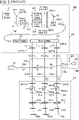
FIG. 3 is a diagram for explaining the configuration of a Mach-Zehnder atomic interferometer of an embodiment (a first example). -
FIG. 4 is a diagram for explaining the configuration of a Mach-Zehnder atomic interferometer of the embodiment (a second example). -
FIG. 5 is a diagram for explaining the configuration of a Mach-Zehnder atomic interferometer of the embodiment (a third example). -
FIG. 6 is a diagram for explaining the configuration of a Mach-Zehnder atomic interferometer of the embodiment (a fourth example). - A description of an embodiment of the present invention is given in connection with, for instance, a Mach-Zehnder atomic interference scheme. It is to be noted that the drawings are provided for the understanding of the embodiment and the size of each component illustrated therein is different from the actual size. For the sake of convenience, a description of the embodiment is based on a Mach-Zehnder atomic interferometer; it is to be noted that the gist of the present invention can be applied to any atomic interference scheme using a moving standing light wave.
- A Mach-Zehnder
atomic interferometer 500 of the embodiment includes "an optical modulating device that adopts an optical configuration including an AOM and guiding a laser beam by an optical fiber" in place of the above-mentioned "retroreflection optical configuration to which an AOM is added". - An
optical system 300 included in the Mach-Zehnderatomic interferometer 500 of the embodiment includes threeoptical modulating devices light waves - Hereinafter, descriptions are given of a first example (see
FIG. 3 ), a second example (seeFIG. 4 ), a third example (seeFIG. 5 ), and a fourth example (seeFIG. 6 ) of the Mach-Zehnderatomic interferometer 500 using the optical modulating device 510x. - A laser beam L (for example, a laser beam which is circularly polarized light) from a
laser source 311 is frequency-shifted by a predetermined frequency by passing through anEOM 312. The frequency-shifted laser beam L is equally divided by anoptical fiber coupler 313a. One of the two laser beams L coming out of theoptical fiber coupler 313a is equally divided by anoptical fiber coupler 313c, and the other of the two laser beams L coming out of theoptical fiber coupler 313a is equally divided by anoptical fiber coupler 313b. One of the two laser beams L coming out of theoptical fiber coupler 313b is equally divided by anoptical fiber coupler 313d, and the other of the two laser beams L coming out of theoptical fiber coupler 313b is equally divided by anoptical fiber coupler 313e. - One of the two laser beams L coming out of the
optical fiber coupler 313c is attenuated by a variable optical attenuator (VOA) 314a and then subjected to shaping so as to be a desired beam La, 1 (for example, a Gaussian beam σa + which is circularly polarized light) by abeam shaper 315a built up of, for example, a lens, a collimator, and so forth. The obtained beam La, 1 enters aninterference system 200. The other of the two laser beams L coming out of theoptical fiber coupler 313c is guided to anAOM 513a, without crossing an atomic beam, by anoptical fiber 511a with one end thereof connected to theoptical fiber coupler 313c by an unillustrated optical connector. An intermediate part of theoptical fiber 511a is not shown inFIG. 3 to make the drawing easily visible. - One of the two laser beams L coming out of the
optical fiber coupler 313d is attenuated by aVOA 314b and then subjected to shaping so as to be a desired beam Lb, 1 (for example, a Gaussian beam σb + which is circularly polarized light) by abeam shaper 315b built up of, for example, a lens, a collimator, and so forth. The obtained beam Lb, 1 enters theinterference system 200. The other of the two laser beams L coming out of theoptical fiber coupler 313d is guided to anAOM 513b, without crossing an atomic beam, by anoptical fiber 511b with one end thereof connected to theoptical fiber coupler 313d by an unillustrated optical connector. An intermediate part of theoptical fiber 511b is not shown inFIG. 3 to make the drawing easily visible. - One of the two laser beams L coming out of the
optical fiber coupler 313e is attenuated by aVOA 314c and then subjected to shaping so as to be a desired beam Lc, 1 (for example, a Gaussian beam σc + which is circularly polarized light) by abeam shaper 315c built up of, for example, a lens, a collimator, and so forth. The obtained beam Lc, 1 enters theinterference system 200. The other of the two laser beams L coming out of theoptical fiber coupler 313e is guided to anAOM 513c, without crossing an atomic beam, by anoptical fiber 511c with one end thereof connected to theoptical fiber coupler 313e by an unillustrated optical connector. An intermediate part of theoptical fiber 511c is not shown inFIG. 3 to make the drawing easily visible. - The other end of the optical fiber 511x (x ∈ {a, b, c}) is connected to the frequency shifter 513x by an optical connector, thus the laser beam L enters the frequency shifter 513x. The frequency of the laser beam L is shifted by the frequency shifter 513x. The amount of shift is determined by the frequency fx of a signal input to the frequency shifter 513x. As a result, the laser beam L is phase-modulated. One end of the optical fiber 514x is connected to the frequency shifter 513x by an optical connector, thus the laser beam L coming out of the frequency shifter 513x enters the optical fiber 514x. The laser beam L comes out of an optical connector attached to the other end of the optical fiber 514x and is subjected to shaping so as to be a desired beam Lx, 2 (for example, a Gaussian beam σx + which is circularly polarized light) by a beam shaper 316x built up of, for example, a lens, a collimator, and so forth. The obtained beam Lx, 2 enters the
interference system 200. - As a result, the laser beam Lx, 1 that has not passed through the optical modulating device 510x and the laser beam Lx, 2 that has passed through the optical modulating device 510x counter-propagate in free space to generate a moving standing light wave 200x (x ∈ {a, b, c}).
- The second example is a modification of the first example. A laser beam L (for example, a laser beam which is circularly polarized light) from a
laser source 311 is frequency-shifted by a predetermined frequency by passing through anEOM 312. The frequency-shifted laser beam L is equally divided by anoptical fiber coupler 313a. One of the two laser beams L coming out of theoptical fiber coupler 313a is attenuated by aVOA 314a and then subjected to shaping so as to be a desired beam La, 1 (for example, a Gaussian beam σa + which is circularly polarized light) by abeam shaper 315a built up of, for example, a lens, a collimator, and so forth. The obtained beam La, 1 enters aninterference system 200. - The other of the two laser beams L coming out of the
optical fiber coupler 313a is equally divided by anoptical fiber coupler 313b. One of the two laser beams L coming out of theoptical fiber coupler 313b is attenuated by aVOA 314b and then subjected to shaping so as to be a desired beam Lb, 1 (for example, a Gaussian beam σb + which is circularly polarized light) by abeam shaper 315b built up of, for example, a lens, a collimator, and so forth. The obtained beam Lb, 1 enters theinterference system 200. The other of the two laser beams L coming out of theoptical fiber coupler 313b is attenuated by aVOA 314c and then subjected to shaping so as to be a desired beam Lc, 1 (for example, a Gaussian beam σc + which is circularly polarized light) by abeam shaper 315c built up of, for example, a lens, a collimator, and so forth. The obtained beam Lc, 1 enters theinterference system 200. - The optical modulating device 510x (x ∈ {a, b, c}) in the second example includes a three-port optical circulator 515x in addition to the components of the optical modulating device 510x in the first example. In the three-port optical circulator 515x, the light that has entered a
port 1 comes out of aport 2 and the light that has entered theport 2 comes out of a port 3. One end of the frequency shifter 513x is connected to one end of the optical fiber 511x, the other end of the optical fiber 511x is connected to a first port of the optical circulator 515x, the other end of the frequency shifter 513x is connected to one end of the optical fiber 514x, and the other end of the optical fiber 514x is connected to a third port of the optical circulator 515x. The optical fibers 511x and 514x are each connected to the frequency shifter 513x by an optical connector. - The beam Lx, 1 obtained by the beam shaper 315x is introduced into a second port of the optical circulator 515x by an optical connector attached to the second port of the optical circulator 515x. This optical connector is an optical connector having a lens collimator, for example. The beam Lx, 1 is transmitted from the second port to the third port, travels along the optical fiber 514x connected to the third port and then enters the frequency shifter 513x. The frequency of the beam Lx, 1 is shifted by the frequency shifter 513x. The amount of shift is determined by the frequency fx of a signal input to the frequency shifter 513x. As a result, the beam Lx, 1 is phase-modulated. The beam Lx, 1 coming out of the frequency shifter 513x is introduced into the first port of the optical circulator 515x via the optical fiber 511x connected to the frequency shifter 513x. The phase-modulated beam Lx, 1 is transmitted from the first port to the second port and comes out of the optical connector as a beam Lx, 2. As a result, the laser beam Lx, 1 that has not passed through the optical modulating device 510x and the laser beam Lx, 2 that has passed through the optical modulating device 510x counter-propagate in free space to generate a moving standing light wave 200x (x ∈ {a, b, c}).
- A four-port optical circulator may be used in place of the three-port optical circulator 515x. In this case, a fourth port is not used. In the four-port optical circulator 515x, the light that has entered a
port 1 comes out of aport 2, the light that has entered theport 2 comes out of a port 3, and the light that has entered the port 3 comes out of a port 4. - A Mach-Zehnder
atomic interferometer 500 of the third example is the same as the Mach-Zehnderatomic interferometer 900 except that the Mach-Zehnderatomic interferometer 500 includes "an optical modulating device that adopts an optical configuration including an AOM and guiding a laser beam by an optical fiber" in place of the above-mentioned "retroreflection optical configuration to which an AOM is added". Therefore, the following description deals with a difference between the Mach-Zehnderatomic interferometer 500 and the Mach-Zehnderatomic interferometer 900, that is, the optical modulating device. Repetitive descriptions of the common matter of the Mach-Zehnderatomic interferometer 500 and the Mach-Zehnderatomic interferometer 900 are omitted by incorporating the description of the above-mentioned Mach-Zehnderatomic interferometer 900 into the description of the third example. - The laser beam L1, x and the laser beam L2, x (x ∈ {a, b, c}) obtained by the
beam divider 306 in the manner described above enter a polarizing beam splitter PBS3x. The laser beam L1, x which is linearly polarized light passes through the polarizing beam splitter PBS3x, and the laser beam L2, x which is linearly polarized light is reflected from the polarizing beam splitter PBS3x at an angle of 90°. The laser beam L1, x passes through a 1/4 wave plate QWPlx and becomes right-handed circularly polarized light σ1, x +, i. The right-handed circularly polarized light σ1, x +, i passes through a 1/4 wave plate QWP2x and enters a polarizing beam splitter PBS4x. The linearly polarized light corresponding to the right-handed circularly polarized light σ1, x +, i is reflected from the polarizing beam splitter PBS4x at an angle of 90° and enters an unillustrated optical isolator. - The laser beam L2, x reflected from the polarizing beam splitter PBS3x passes through a 1/2 wave plate HWP3x and is introduced into the optical fiber 511x, without crossing an atomic beam, by an optical connector attached to one end of the optical fiber 511x. An intermediate part of the optical fiber 511x is not shown in
FIG. 5 to make the drawing easily visible. This optical connector is an optical connector having a lens collimator, for example. The other end of the optical fiber 511x is connected to the frequency shifter 513x, thus the laser beam L2, x enters the frequency shifter 513x. The frequency of the laser beam L2, x is shifted by the frequency shifter 513x. The amount of shift is determined by the frequency fx of a signal input to the frequency shifter 513x. As a result, the laser beam L2, x is phase-modulated. One end of the optical fiber 514x is connected to the frequency shifter 513x, thus the laser beam L2, x coming out of the frequency shifter 513x enters the optical fiber 514x. The optical fibers 511x and 514x are each connected to the frequency shifter 513x by an optical connector. The laser beam L2, x comes out of an optical connector attached to the other end of the optical fiber 514x, passes through the polarizing beam splitter PBS4x, then passes through the 1/4 wave plate QWP2x, and becomes right-handed circularly polarized light σ2, x +, r. As a result, the right-handed circularly polarized light σ1, x +, i, which is derived from the laser beam that is from the polarization-maintaining fiber PMF, and the right-handed circularly polarized light σ2, x +, r, which is derived from the laser beam that is from the optical modulating device 510x, counter-propagate in free space to generate a moving standing light wave 200x (x ∈ {a, b, c}). - The fourth example is a modification of the third example. The optical modulating device 510x in the fourth example includes a three-port optical circulator 515x in addition to the components of the optical modulating device 510x in the third example. One end of the frequency shifter 513x is connected to one end of the optical fiber 511x, the other end of the optical fiber 511x is connected to a first port of the optical circulator 515x, the other end of the frequency shifter 513x is connected to one end of the optical fiber 514x, and the other end of the optical fiber 514x is connected to a third port of the optical circulator 515x. The optical fibers 511x and 514x are each connected to the frequency shifter 513x by an optical connector.
- The laser beam L1, x and the laser beam L2, x (x ∈ {a, b, c}) obtained by the
beam divider 306 pass through a 1/4 wave plate QWPlx and become right-handed circularly polarized light σ1, x +, i and left-handed circularly polarized light σ2, x -, i. The right-handed circularly polarized light σ1, x +, i and the left-handed circularly polarized light σ2, x -, i then pass through a 1/4 wave plate QWP2x and enter a polarizing beam splitter PBS5x. The linearly polarized light corresponding to the right-handed circularly polarized light σ1, x +, i is reflected from the polarizing beam splitter PBS5x at an angle of 90° and enters an unillustrated optical isolator. The linearly polarized light corresponding to the left-handed circularly polarized light σ2, x -, i passes through the polarizing beam splitter PBS5x and is introduced into a second port of the optical circulator 515x by an optical connector attached to the second port of the optical circulator 515x. This optical connector is an optical connector having a lens collimator, for example. This linearly polarized light is transmitted from the second port to the third port, travels along the optical fiber 514x connected to the third port and then enters the frequency shifter 513x. The frequency of the linearly polarized light is shifted by the frequency shifter 513x. The amount of shift is determined by the frequency fx of a signal input to the frequency shifter 513x. As a result, the linearly polarized light is phase-modulated. The linearly polarized light coming out of the frequency shifter 513x is introduced into the first port of the optical circulator 515x via the optical fiber 511x connected to the frequency shifter 513x. The phase-modulated linearly polarized light is transmitted from the first port to the second port and comes out of the optical connector. The linearly polarized light derived from the laser beam L2, x passes through the polarizing beam splitter PBS5x, then passes through the 1/4 wave plate QWP2x, and becomes right-handed circularly polarized light σ2, x +, r. As a result, the right-handed circularly polarized light σ1, x +, i, which is derived from the laser beam that is from the polarization-maintaining fiber PMF, and the right-handed circularly polarized light σ2, x +, r, which is derived from the laser beam that is from the optical modulating device 510x, counter-propagate in free space to generate a moving standing light wave 200x (x ∈ {a, b, c}). - An four-port optical circulator may be used in place of the three-port optical circulator 515x. In this case, a fourth port is not used.
- As is clear from the embodiment described above, unlike the retroreflection optical configuration that removes diffracted light of any unnecessary order in the space between the AOM 307x and the retroreflector RRx, the optical configuration that guides a laser beam by an optical fiber can eliminate diffracted light of any unnecessary order by selection or separation of a propagation mode of an optical fiber. Furthermore, the optical configuration that guides a laser beam by an optical fiber is not subject to design constraints derived from the focal distance of the lens LS2x. In addition, since a core diameter of an optical fiber -- for example, a mode field diameter of a single-mode optical fiber is typically about 0.005 mm -- is sufficiently smaller than a beam diameter of a laser beam incident on the AOM 307x -- the beam diameter is sufficiently greater than an acoustic wave in a crystal and is typically about 0.5 mm --, it is possible to make the focal distance between an optical fiber and a lens for introducing the laser beam propagated in free space into the optical fiber shorter than the distance between the lens LS1x and the AOM 307x. Thus, the optical configuration that guides a laser beam by an optical fiber contributes to implementation of a compact atomic gyroscope and a compact atomic interferometer.
- There is a possibility that the retroreflection optical configuration is affected by the influence of an air current or vibration of a retroreflector or other influences, so that a mechanism for eliminating these influences is needed. According to the present embodiment, the optical modulating device 510x (x ∈ {a, b, c}) is not affected by the influence of vibration of a retroreflector because the optical modulating device 510x (x ∈ {a, b, c}) does not include a retroreflector. Since the optical modulating device 510x includes the optical fibers 511x and 514x, it would be an overstatement to say that there is no possibility that the optical fibers 511x and 514x are affected by the influence of an air current; however, some techniques are already known to cancel errors occurred by vibration of the optical fibers 511x and 514x due to an air current or the like (see Reference Literature 1). For that matter, the securing of the optical fibers 511x and 514x with, for instance, fastenings helps to reduce the possibility that the optical fibers 511x and 514x are affected by the influence of an air current. (Reference Literature 1) Longsheng Ma, et al., "Delivering the same optical frequency at two places: accurate cancellation of phase noise introduced by an optical fiber or other time-varying path," Optics letters (1994), Vol. 19, No. 21, 1777-1779.
- When the Mach-Zehnder
atomic interferometer 500 is used as an atomic gyroscope, themonitor 400 may detect angular velocity or acceleration on the basis of the population of atoms in an excited state. The detecting of angular velocity or acceleration on the basis of the population of atoms in an excited state is a well-known technique and therefore descriptions thereof are omitted. - The embodiment described above adopts the Mach-Zehnder atomic interference scheme; a Ramsey-Borde atomic interference scheme, for example, may be adopted instead.
- A moving standing light wave 200x (x ∈ {a, b, c}) may be obtained from left-handed circularly polarized light σ1, x -, i, which is derived from a laser beam that is from a polarization-maintaining fiber, and left-handed circularly polarized light σ2, x -, r, which is derived from a laser beam that is from the optical modulating device 510x (x ∈ {a, b, c}).
- Furthermore, the embodiment described above refers to, as an example, Mach-Zehnder atomic interference in which one splitting, one reversal, and one mixing are performed using three moving standing light waves; the present invention is not limited to such an embodiment and can be carried out as, for example, an embodiment using multistage Mach-Zehnder atomic interference in which more than one splitting, more than one reversal, and more than one mixing are performed.
See Reference Literature 2 about such multistage Mach-Zehnder atomic interference. (Reference Literature 2) Takatoshi Aoki et al., "High-finesse atomic multiple-beam interferometer comprised of copropagating stimulated Raman-pulse fields," Phys. Rev. A 63, 063611 (2001) - Published 16 May 2001. - In the claims and the specification, unless otherwise noted, the term "connected" and every inflected form thereof do not necessarily deny that one or more intermediate elements are present between two elements "connected" to each other.
- In the claims and the specification, unless otherwise noted, an ordinal numeral is not intended to limit an element modified by or coupled to the ordinal numeral by an ordinal position or the amount of the element. Unless otherwise noted, an ordinal numeral is merely used as a convenient expression method to distinguish two or more elements from one another. Thus, for example, the phrase "a first X" and the phrase "a second X" are expressions to distinguish between two Xs and do not necessarily mean that the total number of Xs is 2 or do not necessarily mean that the first X has to come before the second X. The term "first" does not necessarily mean "coming before all others in order".
- In the claims and the specification, the term "include" and inflected forms thereof are used as non-exclusive expressions. For example, the sentence "X includes A and B" does not deny that X includes a component other than A and B, for example, C. Moreover, when a certain sentence includes a phrase in which the term "include" or an inflected form thereof is coupled to a negative word, for example, "not include", the sentence only makes mention of the object of the phrase. Thus, for example, the sentence "X does not include A and B" acknowledges a possibility that X includes a component other than A and B. In addition, the term "or" is not intended to mean an exclusive OR.
- The foregoing description of the embodiment of the invention has been presented for the purpose of illustration and description. It is not intended to be exhaustive and to limit the invention to the precise form disclosed. Modifications or variations are possible in light of the above teaching. The embodiment was chosen and described to provide the best illustration of the principles of the invention and its practical application, and to enable one of ordinary skill in the art to utilize the invention in various embodiments and with various modifications as are suited to the particular use contemplated. All such modifications and variations are within the scope of the invention as determined by the appended claims when interpreted in accordance with the breadth to which they are fairly, legally, and equitably entitled.
-
- 100 atomic beam source
- 100a atomic beam
- 100b atomic beam
- 200 interference system
- 200a first moving standing light wave
- 200b second moving standing light wave
- 200c third moving standing light wave
- 300 optical system
- 301 master laser source
- 302 EOM
- 303 first slave laser source
- 304 second slave laser source
- 305 beam shaper
- 306 beam divider
- 307a AOM
- 307b AOM
- 307c AOM
- 311 laser source
- 312 EOM
- 313a optical fiber coupler
- 313b optical fiber coupler
- 313c optical fiber coupler
- 313d optical fiber coupler
- 313e optical fiber coupler
- 314a VOA
- 314b VOA
- 314c VOA
- 315a beam shaper
- 315b beam shaper
- 315c beam shaper
- 316a beam shaper
- 316b beam shaper
- 316c beam shaper
- 400 monitor
- 408 probe beam
- 409 photodetector
- 500 Mach-Zehnder atomic interferometer
- 510a optical modulating device
- 510b optical modulating device
- 510c optical modulating device
- 511a optical fiber
- 511b optical fiber
- 511c optical fiber
- 513a frequency shifter
- 513b frequency shifter
- 513c frequency shifter
- 514a optical fiber
- 514b optical fiber
- 514c optical fiber
- 515a optical circulator
- 515b optical circulator
- 515c optical circulator
- 900 Mach-Zehnder atomic interferometer
- BS1 beam splitter
-
HWP1 1/2 wave plate -
HWP2 1/2 wave plate -
HWP3a 1/2 wave plate -
HWP3b 1/2 wave plate -
HWP3c 1/2 wave plate - LS1a lens
- LSlb lens
- LS1c lens
- LS2a lens
- LS2b lens
- LS2c lens
- M1 mirror
- M2 mirror
- ML master laser beam
- PBS1 polarizing beam splitter
- PBS2a polarizing beam splitter
- PBS2b polarizing beam splitter
- PBS2c polarizing beam splitter
- PBS3a polarizing beam splitter
- PBS3b polarizing beam splitter
- PBS3c polarizing beam splitter
- PBS4a polarizing beam splitter
- PBS4b polarizing beam splitter
- PBS4c polarizing beam splitter
- PBS5a polarizing beam splitter
- PBS5b polarizing beam splitter
- PBS5c polarizing beam splitter
- PMF polarization-maintaining fiber
-
QWP1a 1/4 wave plate -
QWPlb 1/4 wave plate -
QWP1c 1/4 wave plate -
QWP2a 1/4 wave plate -
QWP2b 1/4 wave plate -
QWP2c 1/4 wave plate - RRa retroreflector
- RRb retroreflector
- RRc retroreflector
- SL1 first slave laser beam
- SL2 second slave laser beam
Claims (5)
- An atomic gyroscope comprising:an optical means including an optical modulation means that includes: an optical fiber for a first laser beam to propagate therein; and a frequency shift means connected to the optical fiber and adapted to shift a frequency of the first laser beam, the optical means being adapted to generate a moving standing light wave from counter-propagation of the first laser beam from the optical modulation means and a second laser beam;an interference means for making an atomic beam interact with three or more moving standing light waves including the moving standing light wave; anda monitoring means for detecting angular velocity or acceleration by monitoring the atomic beam from the interference means.
- The atomic gyroscope according to Claim 1, whereinthe optical modulation means further includes an optical circulator,the optical circulator has a first port thereof connected to one end of the frequency shift means,the optical circulator has a third port thereof connected to the other end of the frequency shift means, andthe optical circulator has a second port thereof for the first laser beam to enter.
- The atomic gyroscope according to Claim 1, wherein
the first laser beam enters the optical fiber without crossing the atomic beam. - The atomic gyroscope according to any one of Claims 1 to 3,
wherein
the frequency shift means is an acousto-optic modulator or an electro-optic modulator. - An atomic interferometer comprising:an optical means including an optical modulation means that includes: an optical fiber for a first laser beam to propagate therein; and a frequency shift means connected to the optical fiber and adapted to shift a frequency of the first laser beam, the optical means being adapted to generate a moving standing light wave from counter-propagation of the first laser beam from the optical modulation means and a second laser beam; andan interference means for making an atomic beam interact with three or more moving standing light waves including the moving standing light wave.
Applications Claiming Priority (2)
| Application Number | Priority Date | Filing Date | Title |
|---|---|---|---|
| JP2019234570A JP6818332B1 (en) | 2019-12-25 | 2019-12-25 | Atomic gyroscope, atom interferometer |
| PCT/JP2020/035894 WO2021131189A1 (en) | 2019-12-25 | 2020-09-24 | Atomic gyroscope and atomic interferometer |
Publications (3)
| Publication Number | Publication Date |
|---|---|
| EP4083573A1 true EP4083573A1 (en) | 2022-11-02 |
| EP4083573A4 EP4083573A4 (en) | 2023-06-28 |
| EP4083573B1 EP4083573B1 (en) | 2024-07-03 |
Family
ID=74164719
Family Applications (1)
| Application Number | Title | Priority Date | Filing Date |
|---|---|---|---|
| EP20906053.2A Active EP4083573B1 (en) | 2019-12-25 | 2020-09-24 | Atomic gyroscope and atomic interferometer |
Country Status (5)
| Country | Link |
|---|---|
| US (1) | US11808577B2 (en) |
| EP (1) | EP4083573B1 (en) |
| JP (1) | JP6818332B1 (en) |
| AU (1) | AU2020415534B2 (en) |
| WO (1) | WO2021131189A1 (en) |
Families Citing this family (8)
| Publication number | Priority date | Publication date | Assignee | Title |
|---|---|---|---|---|
| JP6713643B2 (en) * | 2018-12-07 | 2020-06-24 | 日本航空電子工業株式会社 | Atomic beam collimation method, atomic beam collimator, atomic interferometer, atomic gyroscope |
| JP6948656B1 (en) | 2020-10-08 | 2021-10-13 | 日本航空電子工業株式会社 | Inertia sensor, atom interferometer, method of adjusting atomic speed, device for adjusting atomic speed |
| JP6948655B1 (en) | 2020-10-08 | 2021-10-13 | 日本航空電子工業株式会社 | Inertia sensor, atom interferometer, method of adjusting the speed and course of atomic rays, device for adjusting the speed and course of atomic rays |
| CN113514046B (en) * | 2021-07-08 | 2022-11-25 | 北京航空航天大学 | Device and method for detecting atomic spin precession signal based on Mach-Zehnder interference |
| CN116183961B (en) * | 2023-01-17 | 2025-10-28 | 北京大学 | A fiber optic angular accelerometer capable of suppressing light source noise |
| JP2025014818A (en) | 2023-07-19 | 2025-01-30 | 日本航空電子工業株式会社 | Quantum collimation method for atomic beam, quantum collimator for atomic beam, atom interferometer, and atomic gyroscope |
| JP2025022116A (en) * | 2023-08-02 | 2025-02-14 | 国立大学法人東京科学大学 | Inertial Sensors |
| CN119756451B (en) * | 2024-12-30 | 2025-09-30 | 华中光电技术研究所(中国船舶集团有限公司第七一七研究所) | Output value correction method of cold atom interferometry equipment under motion condition |
Family Cites Families (9)
| Publication number | Priority date | Publication date | Assignee | Title |
|---|---|---|---|---|
| US5315109A (en) * | 1992-10-06 | 1994-05-24 | Duke University | Position measurement of moving atoms using optical fields |
| CN102538775B (en) | 2010-12-24 | 2014-08-06 | 清华大学 | Cold atom beam interference gyro device |
| US9019506B1 (en) * | 2012-01-31 | 2015-04-28 | AOSense, Inc. | Phase control for dual atom interferometers |
| US9568316B2 (en) * | 2013-03-15 | 2017-02-14 | The Charles Stark Draper Laboratory, Inc. | Ring architecture for sequential operation of an atomic gyroscope |
| US9952154B2 (en) | 2016-06-22 | 2018-04-24 | The Charles Stark Draper Laboratory, Inc. | Separated parallel beam generation for atom interferometry |
| KR101871213B1 (en) * | 2016-08-31 | 2018-08-02 | 국방과학연구소 | Atom interferometer gyroscope based on single raman laser beam |
| AU2018349505A1 (en) | 2017-10-10 | 2020-04-23 | Japan Aviation Electronics Industry, Limited | Mach-zehnder type atomic interferometric gyroscope |
| US10444016B1 (en) * | 2018-06-26 | 2019-10-15 | AOSense, Inc. | Automatic biasing and closed loop control of an atomic interferometer |
| US10801840B1 (en) * | 2019-07-24 | 2020-10-13 | Honeywell International Inc. | Four port atomic gyroscope |
-
2019
- 2019-12-25 JP JP2019234570A patent/JP6818332B1/en active Active
-
2020
- 2020-09-24 EP EP20906053.2A patent/EP4083573B1/en active Active
- 2020-09-24 WO PCT/JP2020/035894 patent/WO2021131189A1/en not_active Ceased
- 2020-09-24 US US17/780,668 patent/US11808577B2/en active Active
- 2020-09-24 AU AU2020415534A patent/AU2020415534B2/en active Active
Also Published As
| Publication number | Publication date |
|---|---|
| US20230011067A1 (en) | 2023-01-12 |
| JP2021103128A (en) | 2021-07-15 |
| JP6818332B1 (en) | 2021-01-20 |
| WO2021131189A1 (en) | 2021-07-01 |
| EP4083573A4 (en) | 2023-06-28 |
| AU2020415534A1 (en) | 2022-06-09 |
| EP4083573B1 (en) | 2024-07-03 |
| AU2020415534B2 (en) | 2024-03-14 |
| US11808577B2 (en) | 2023-11-07 |
Similar Documents
| Publication | Publication Date | Title |
|---|---|---|
| AU2020415534B2 (en) | Atomic gyroscope and atomic interferometer | |
| Lloyd et al. | Modeling coherent backscattering errors in fiber optic gyroscopes for sources of arbitrary line width | |
| Danilishin et al. | A new quantum speed-meter interferometer: measuring speed to search for intermediate mass black holes | |
| Xue et al. | A continuous cold atomic beam interferometer | |
| CN105277188B (en) | Sagnac angular velocity measurement system and methods | |
| Hilweg et al. | Gravitationally induced phase shift on a single photon | |
| AU2021357884B2 (en) | Inertial sensor, atomic interferometer, method for adjusting speed and course of atomic beam, and apparatus for adjusting speed and course of atomic beam | |
| EP4206686B1 (en) | Inertia sensor, atom interferometer, method for adjusting speed of atom, and device for adjusting speed of atom | |
| WO2017190055A1 (en) | Nonlinear interferometer systems and methods | |
| EP3680614A1 (en) | Gyroscope based on mach-zehnder-type atomic interference | |
| JPWO2019073701A1 (en) | Dual optical frequency comb generation optical system, laser device, measuring device | |
| US20250020446A1 (en) | Laser architecture for component efficient atomic interferometer gravimeter | |
| CN105278205B (en) | The method for eliminating parasitic in full light Sagnac interferometers | |
| Zhai et al. | Fiber-optic quantum gyroscope based on Hong-Ou-Mandel interferometry | |
| Liu et al. | Polarization non-reciprocity error suppression in dual-polarization fiber optic gyroscopes | |
| JP2025022116A (en) | Inertial Sensors | |
| Wang | Dual-polarization two-port fiber-optic gyroscope | |
| JP7722738B2 (en) | Carrier envelope phase measuring device, stabilized light source, and carrier envelope phase measuring method | |
| Galica | Polychromatic Optical Forces in Diatomic Systems | |
| RU2488862C1 (en) | Method for coherent laser beam combining with synchronous detection and apparatus for coherent laser beam combining with synchronous detection | |
| Hong et al. | A novel all‐fiber velocity interferometer with high fringe contrast | |
| Martienssen et al. | 1 Coherence: 6 Coherence and superradiance |
Legal Events
| Date | Code | Title | Description |
|---|---|---|---|
| STAA | Information on the status of an ep patent application or granted ep patent |
Free format text: STATUS: THE INTERNATIONAL PUBLICATION HAS BEEN MADE |
|
| PUAI | Public reference made under article 153(3) epc to a published international application that has entered the european phase |
Free format text: ORIGINAL CODE: 0009012 |
|
| STAA | Information on the status of an ep patent application or granted ep patent |
Free format text: STATUS: REQUEST FOR EXAMINATION WAS MADE |
|
| 17P | Request for examination filed |
Effective date: 20220725 |
|
| AK | Designated contracting states |
Kind code of ref document: A1 Designated state(s): AL AT BE BG CH CY CZ DE DK EE ES FI FR GB GR HR HU IE IS IT LI LT LU LV MC MK MT NL NO PL PT RO RS SE SI SK SM TR |
|
| DAV | Request for validation of the european patent (deleted) | ||
| DAX | Request for extension of the european patent (deleted) | ||
| A4 | Supplementary search report drawn up and despatched |
Effective date: 20230601 |
|
| RIC1 | Information provided on ipc code assigned before grant |
Ipc: G02F 2/02 20060101ALI20230525BHEP Ipc: G02F 1/11 20060101ALI20230525BHEP Ipc: G01P 15/00 20060101ALI20230525BHEP Ipc: G01C 19/58 20060101AFI20230525BHEP |
|
| GRAP | Despatch of communication of intention to grant a patent |
Free format text: ORIGINAL CODE: EPIDOSNIGR1 |
|
| STAA | Information on the status of an ep patent application or granted ep patent |
Free format text: STATUS: GRANT OF PATENT IS INTENDED |
|
| INTG | Intention to grant announced |
Effective date: 20240124 |
|
| GRAS | Grant fee paid |
Free format text: ORIGINAL CODE: EPIDOSNIGR3 |
|
| GRAA | (expected) grant |
Free format text: ORIGINAL CODE: 0009210 |
|
| STAA | Information on the status of an ep patent application or granted ep patent |
Free format text: STATUS: THE PATENT HAS BEEN GRANTED |
|
| RAP3 | Party data changed (applicant data changed or rights of an application transferred) |
Owner name: TOKYO INSTITUTE OF TECHNOLOGY Owner name: JAPAN AVIATION ELECTRONICS INDUSTRY, LIMITED |
|
| AK | Designated contracting states |
Kind code of ref document: B1 Designated state(s): AL AT BE BG CH CY CZ DE DK EE ES FI FR GB GR HR HU IE IS IT LI LT LU LV MC MK MT NL NO PL PT RO RS SE SI SK SM TR |
|
| REG | Reference to a national code |
Ref country code: CH Ref legal event code: EP |
|
| REG | Reference to a national code |
Ref country code: DE Ref legal event code: R096 Ref document number: 602020033560 Country of ref document: DE |
|
| REG | Reference to a national code |
Ref country code: LT Ref legal event code: MG9D |
|
| RAP4 | Party data changed (patent owner data changed or rights of a patent transferred) |
Owner name: TOKYO INSTITUTE OF TECHNOLOGY Owner name: JAPAN AVIATION ELECTRONICS INDUSTRY, LIMITED |
|
| REG | Reference to a national code |
Ref country code: NL Ref legal event code: MP Effective date: 20240703 |
|
| PG25 | Lapsed in a contracting state [announced via postgrant information from national office to epo] |
Ref country code: PT Free format text: LAPSE BECAUSE OF FAILURE TO SUBMIT A TRANSLATION OF THE DESCRIPTION OR TO PAY THE FEE WITHIN THE PRESCRIBED TIME-LIMIT Effective date: 20241104 |
|
| REG | Reference to a national code |
Ref country code: AT Ref legal event code: MK05 Ref document number: 1700228 Country of ref document: AT Kind code of ref document: T Effective date: 20240703 |
|
| PG25 | Lapsed in a contracting state [announced via postgrant information from national office to epo] |
Ref country code: NL Free format text: LAPSE BECAUSE OF FAILURE TO SUBMIT A TRANSLATION OF THE DESCRIPTION OR TO PAY THE FEE WITHIN THE PRESCRIBED TIME-LIMIT Effective date: 20240703 |
|
| PG25 | Lapsed in a contracting state [announced via postgrant information from national office to epo] |
Ref country code: PT Free format text: LAPSE BECAUSE OF FAILURE TO SUBMIT A TRANSLATION OF THE DESCRIPTION OR TO PAY THE FEE WITHIN THE PRESCRIBED TIME-LIMIT Effective date: 20241104 Ref country code: NL Free format text: LAPSE BECAUSE OF FAILURE TO SUBMIT A TRANSLATION OF THE DESCRIPTION OR TO PAY THE FEE WITHIN THE PRESCRIBED TIME-LIMIT Effective date: 20240703 |
|
| PG25 | Lapsed in a contracting state [announced via postgrant information from national office to epo] |
Ref country code: NO Free format text: LAPSE BECAUSE OF FAILURE TO SUBMIT A TRANSLATION OF THE DESCRIPTION OR TO PAY THE FEE WITHIN THE PRESCRIBED TIME-LIMIT Effective date: 20241003 |
|
| PG25 | Lapsed in a contracting state [announced via postgrant information from national office to epo] |
Ref country code: GR Free format text: LAPSE BECAUSE OF FAILURE TO SUBMIT A TRANSLATION OF THE DESCRIPTION OR TO PAY THE FEE WITHIN THE PRESCRIBED TIME-LIMIT Effective date: 20241004 Ref country code: FI Free format text: LAPSE BECAUSE OF FAILURE TO SUBMIT A TRANSLATION OF THE DESCRIPTION OR TO PAY THE FEE WITHIN THE PRESCRIBED TIME-LIMIT Effective date: 20240703 Ref country code: PL Free format text: LAPSE BECAUSE OF FAILURE TO SUBMIT A TRANSLATION OF THE DESCRIPTION OR TO PAY THE FEE WITHIN THE PRESCRIBED TIME-LIMIT Effective date: 20240703 |
|
| PG25 | Lapsed in a contracting state [announced via postgrant information from national office to epo] |
Ref country code: BG Free format text: LAPSE BECAUSE OF FAILURE TO SUBMIT A TRANSLATION OF THE DESCRIPTION OR TO PAY THE FEE WITHIN THE PRESCRIBED TIME-LIMIT Effective date: 20240703 |
|
| PG25 | Lapsed in a contracting state [announced via postgrant information from national office to epo] |
Ref country code: LV Free format text: LAPSE BECAUSE OF FAILURE TO SUBMIT A TRANSLATION OF THE DESCRIPTION OR TO PAY THE FEE WITHIN THE PRESCRIBED TIME-LIMIT Effective date: 20240703 |
|
| PG25 | Lapsed in a contracting state [announced via postgrant information from national office to epo] |
Ref country code: IS Free format text: LAPSE BECAUSE OF FAILURE TO SUBMIT A TRANSLATION OF THE DESCRIPTION OR TO PAY THE FEE WITHIN THE PRESCRIBED TIME-LIMIT Effective date: 20241103 Ref country code: AT Free format text: LAPSE BECAUSE OF FAILURE TO SUBMIT A TRANSLATION OF THE DESCRIPTION OR TO PAY THE FEE WITHIN THE PRESCRIBED TIME-LIMIT Effective date: 20240703 |
|
| PG25 | Lapsed in a contracting state [announced via postgrant information from national office to epo] |
Ref country code: CZ Free format text: LAPSE BECAUSE OF FAILURE TO SUBMIT A TRANSLATION OF THE DESCRIPTION OR TO PAY THE FEE WITHIN THE PRESCRIBED TIME-LIMIT Effective date: 20240703 Ref country code: HR Free format text: LAPSE BECAUSE OF FAILURE TO SUBMIT A TRANSLATION OF THE DESCRIPTION OR TO PAY THE FEE WITHIN THE PRESCRIBED TIME-LIMIT Effective date: 20240703 |
|
| PG25 | Lapsed in a contracting state [announced via postgrant information from national office to epo] |
Ref country code: RS Free format text: LAPSE BECAUSE OF FAILURE TO SUBMIT A TRANSLATION OF THE DESCRIPTION OR TO PAY THE FEE WITHIN THE PRESCRIBED TIME-LIMIT Effective date: 20241003 Ref country code: ES Free format text: LAPSE BECAUSE OF FAILURE TO SUBMIT A TRANSLATION OF THE DESCRIPTION OR TO PAY THE FEE WITHIN THE PRESCRIBED TIME-LIMIT Effective date: 20240703 |
|
| PG25 | Lapsed in a contracting state [announced via postgrant information from national office to epo] |
Ref country code: RS Free format text: LAPSE BECAUSE OF FAILURE TO SUBMIT A TRANSLATION OF THE DESCRIPTION OR TO PAY THE FEE WITHIN THE PRESCRIBED TIME-LIMIT Effective date: 20241003 Ref country code: PL Free format text: LAPSE BECAUSE OF FAILURE TO SUBMIT A TRANSLATION OF THE DESCRIPTION OR TO PAY THE FEE WITHIN THE PRESCRIBED TIME-LIMIT Effective date: 20240703 Ref country code: NO Free format text: LAPSE BECAUSE OF FAILURE TO SUBMIT A TRANSLATION OF THE DESCRIPTION OR TO PAY THE FEE WITHIN THE PRESCRIBED TIME-LIMIT Effective date: 20241003 Ref country code: LV Free format text: LAPSE BECAUSE OF FAILURE TO SUBMIT A TRANSLATION OF THE DESCRIPTION OR TO PAY THE FEE WITHIN THE PRESCRIBED TIME-LIMIT Effective date: 20240703 Ref country code: IS Free format text: LAPSE BECAUSE OF FAILURE TO SUBMIT A TRANSLATION OF THE DESCRIPTION OR TO PAY THE FEE WITHIN THE PRESCRIBED TIME-LIMIT Effective date: 20241103 Ref country code: HR Free format text: LAPSE BECAUSE OF FAILURE TO SUBMIT A TRANSLATION OF THE DESCRIPTION OR TO PAY THE FEE WITHIN THE PRESCRIBED TIME-LIMIT Effective date: 20240703 Ref country code: GR Free format text: LAPSE BECAUSE OF FAILURE TO SUBMIT A TRANSLATION OF THE DESCRIPTION OR TO PAY THE FEE WITHIN THE PRESCRIBED TIME-LIMIT Effective date: 20241004 Ref country code: FI Free format text: LAPSE BECAUSE OF FAILURE TO SUBMIT A TRANSLATION OF THE DESCRIPTION OR TO PAY THE FEE WITHIN THE PRESCRIBED TIME-LIMIT Effective date: 20240703 Ref country code: ES Free format text: LAPSE BECAUSE OF FAILURE TO SUBMIT A TRANSLATION OF THE DESCRIPTION OR TO PAY THE FEE WITHIN THE PRESCRIBED TIME-LIMIT Effective date: 20240703 Ref country code: CZ Free format text: LAPSE BECAUSE OF FAILURE TO SUBMIT A TRANSLATION OF THE DESCRIPTION OR TO PAY THE FEE WITHIN THE PRESCRIBED TIME-LIMIT Effective date: 20240703 Ref country code: BG Free format text: LAPSE BECAUSE OF FAILURE TO SUBMIT A TRANSLATION OF THE DESCRIPTION OR TO PAY THE FEE WITHIN THE PRESCRIBED TIME-LIMIT Effective date: 20240703 Ref country code: AT Free format text: LAPSE BECAUSE OF FAILURE TO SUBMIT A TRANSLATION OF THE DESCRIPTION OR TO PAY THE FEE WITHIN THE PRESCRIBED TIME-LIMIT Effective date: 20240703 |
|
| REG | Reference to a national code |
Ref country code: DE Ref legal event code: R097 Ref document number: 602020033560 Country of ref document: DE |
|
| PG25 | Lapsed in a contracting state [announced via postgrant information from national office to epo] |
Ref country code: DK Free format text: LAPSE BECAUSE OF FAILURE TO SUBMIT A TRANSLATION OF THE DESCRIPTION OR TO PAY THE FEE WITHIN THE PRESCRIBED TIME-LIMIT Effective date: 20240703 Ref country code: RO Free format text: LAPSE BECAUSE OF FAILURE TO SUBMIT A TRANSLATION OF THE DESCRIPTION OR TO PAY THE FEE WITHIN THE PRESCRIBED TIME-LIMIT Effective date: 20240703 Ref country code: SM Free format text: LAPSE BECAUSE OF FAILURE TO SUBMIT A TRANSLATION OF THE DESCRIPTION OR TO PAY THE FEE WITHIN THE PRESCRIBED TIME-LIMIT Effective date: 20240703 |
|
| PG25 | Lapsed in a contracting state [announced via postgrant information from national office to epo] |
Ref country code: MC Free format text: LAPSE BECAUSE OF FAILURE TO SUBMIT A TRANSLATION OF THE DESCRIPTION OR TO PAY THE FEE WITHIN THE PRESCRIBED TIME-LIMIT Effective date: 20240703 Ref country code: EE Free format text: LAPSE BECAUSE OF FAILURE TO SUBMIT A TRANSLATION OF THE DESCRIPTION OR TO PAY THE FEE WITHIN THE PRESCRIBED TIME-LIMIT Effective date: 20240703 |
|
| PG25 | Lapsed in a contracting state [announced via postgrant information from national office to epo] |
Ref country code: IT Free format text: LAPSE BECAUSE OF FAILURE TO SUBMIT A TRANSLATION OF THE DESCRIPTION OR TO PAY THE FEE WITHIN THE PRESCRIBED TIME-LIMIT Effective date: 20240703 Ref country code: SK Free format text: LAPSE BECAUSE OF FAILURE TO SUBMIT A TRANSLATION OF THE DESCRIPTION OR TO PAY THE FEE WITHIN THE PRESCRIBED TIME-LIMIT Effective date: 20240703 |
|
| REG | Reference to a national code |
Ref country code: CH Ref legal event code: PL |
|
| PLBE | No opposition filed within time limit |
Free format text: ORIGINAL CODE: 0009261 |
|
| STAA | Information on the status of an ep patent application or granted ep patent |
Free format text: STATUS: NO OPPOSITION FILED WITHIN TIME LIMIT |
|
| PG25 | Lapsed in a contracting state [announced via postgrant information from national office to epo] |
Ref country code: LU Free format text: LAPSE BECAUSE OF NON-PAYMENT OF DUE FEES Effective date: 20240924 |
|
| 26N | No opposition filed |
Effective date: 20250404 |
|
| REG | Reference to a national code |
Ref country code: BE Ref legal event code: MM Effective date: 20240930 |
|
| PG25 | Lapsed in a contracting state [announced via postgrant information from national office to epo] |
Ref country code: BE Free format text: LAPSE BECAUSE OF NON-PAYMENT OF DUE FEES Effective date: 20240930 |
|
| PG25 | Lapsed in a contracting state [announced via postgrant information from national office to epo] |
Ref country code: CH Free format text: LAPSE BECAUSE OF NON-PAYMENT OF DUE FEES Effective date: 20240930 |
|
| PG25 | Lapsed in a contracting state [announced via postgrant information from national office to epo] |
Ref country code: IE Free format text: LAPSE BECAUSE OF NON-PAYMENT OF DUE FEES Effective date: 20240924 |
|
| PG25 | Lapsed in a contracting state [announced via postgrant information from national office to epo] |
Ref country code: SE Free format text: LAPSE BECAUSE OF FAILURE TO SUBMIT A TRANSLATION OF THE DESCRIPTION OR TO PAY THE FEE WITHIN THE PRESCRIBED TIME-LIMIT Effective date: 20240703 |
|
| PGFP | Annual fee paid to national office [announced via postgrant information from national office to epo] |
Ref country code: DE Payment date: 20250730 Year of fee payment: 6 |
|
| PGFP | Annual fee paid to national office [announced via postgrant information from national office to epo] |
Ref country code: GB Payment date: 20250731 Year of fee payment: 6 |
|
| PGFP | Annual fee paid to national office [announced via postgrant information from national office to epo] |
Ref country code: FR Payment date: 20250808 Year of fee payment: 6 |
|
| PG25 | Lapsed in a contracting state [announced via postgrant information from national office to epo] |
Ref country code: CY Free format text: LAPSE BECAUSE OF FAILURE TO SUBMIT A TRANSLATION OF THE DESCRIPTION OR TO PAY THE FEE WITHIN THE PRESCRIBED TIME-LIMIT; INVALID AB INITIO Effective date: 20200924 |
|
| PG25 | Lapsed in a contracting state [announced via postgrant information from national office to epo] |
Ref country code: HU Free format text: LAPSE BECAUSE OF FAILURE TO SUBMIT A TRANSLATION OF THE DESCRIPTION OR TO PAY THE FEE WITHIN THE PRESCRIBED TIME-LIMIT; INVALID AB INITIO Effective date: 20200924 |