EP4083566B1 - Cover system for laser accessory device - Google Patents
Cover system for laser accessory device Download PDFInfo
- Publication number
- EP4083566B1 EP4083566B1 EP22165464.3A EP22165464A EP4083566B1 EP 4083566 B1 EP4083566 B1 EP 4083566B1 EP 22165464 A EP22165464 A EP 22165464A EP 4083566 B1 EP4083566 B1 EP 4083566B1
- Authority
- EP
- European Patent Office
- Prior art keywords
- laser
- accessory device
- cover
- housing
- safety cover
- Prior art date
- Legal status (The legal status is an assumption and is not a legal conclusion. Google has not performed a legal analysis and makes no representation as to the accuracy of the status listed.)
- Active
Links
Images




Classifications
-
- F—MECHANICAL ENGINEERING; LIGHTING; HEATING; WEAPONS; BLASTING
- F41—WEAPONS
- F41G—WEAPON SIGHTS; AIMING
- F41G11/00—Details of sighting or aiming apparatus; Accessories
-
- F—MECHANICAL ENGINEERING; LIGHTING; HEATING; WEAPONS; BLASTING
- F41—WEAPONS
- F41G—WEAPON SIGHTS; AIMING
- F41G3/00—Aiming or laying means
- F41G3/26—Teaching or practice apparatus for gun-aiming or gun-laying
- F41G3/2616—Teaching or practice apparatus for gun-aiming or gun-laying using a light emitting device
-
- F—MECHANICAL ENGINEERING; LIGHTING; HEATING; WEAPONS; BLASTING
- F41—WEAPONS
- F41A—FUNCTIONAL FEATURES OR DETAILS COMMON TO BOTH SMALLARMS AND ORDNANCE, e.g. CANNONS; MOUNTINGS FOR SMALLARMS OR ORDNANCE
- F41A35/00—Accessories or details not otherwise provided for
- F41A35/02—Dust- or weather-protection caps or covers
-
- F—MECHANICAL ENGINEERING; LIGHTING; HEATING; WEAPONS; BLASTING
- F41—WEAPONS
- F41G—WEAPON SIGHTS; AIMING
- F41G1/00—Sighting devices
- F41G1/32—Night sights, e.g. luminescent
- F41G1/34—Night sights, e.g. luminescent combined with light source, e.g. spot light
- F41G1/35—Night sights, e.g. luminescent combined with light source, e.g. spot light for illuminating the target, e.g. flash lights
-
- F—MECHANICAL ENGINEERING; LIGHTING; HEATING; WEAPONS; BLASTING
- F41—WEAPONS
- F41G—WEAPON SIGHTS; AIMING
- F41G1/00—Sighting devices
- F41G1/38—Telescopic sights specially adapted for smallarms or ordnance; Supports or mountings therefor
- F41G1/383—Protection means therefor
-
- F—MECHANICAL ENGINEERING; LIGHTING; HEATING; WEAPONS; BLASTING
- F41—WEAPONS
- F41G—WEAPON SIGHTS; AIMING
- F41G3/00—Aiming or laying means
- F41G3/26—Teaching or practice apparatus for gun-aiming or gun-laying
- F41G3/2616—Teaching or practice apparatus for gun-aiming or gun-laying using a light emitting device
- F41G3/2622—Teaching or practice apparatus for gun-aiming or gun-laying using a light emitting device for simulating the firing of a gun or the trajectory of a projectile
- F41G3/2655—Teaching or practice apparatus for gun-aiming or gun-laying using a light emitting device for simulating the firing of a gun or the trajectory of a projectile in which the light beam is sent from the weapon to the target
-
- F—MECHANICAL ENGINEERING; LIGHTING; HEATING; WEAPONS; BLASTING
- F41—WEAPONS
- F41G—WEAPON SIGHTS; AIMING
- F41G3/00—Aiming or laying means
- F41G3/26—Teaching or practice apparatus for gun-aiming or gun-laying
- F41G3/2616—Teaching or practice apparatus for gun-aiming or gun-laying using a light emitting device
- F41G3/2622—Teaching or practice apparatus for gun-aiming or gun-laying using a light emitting device for simulating the firing of a gun or the trajectory of a projectile
- F41G3/2666—Teaching or practice apparatus for gun-aiming or gun-laying using a light emitting device for simulating the firing of a gun or the trajectory of a projectile with means for selecting or varying PRF or time coding of the emitted beam
-
- F—MECHANICAL ENGINEERING; LIGHTING; HEATING; WEAPONS; BLASTING
- F41—WEAPONS
- F41G—WEAPON SIGHTS; AIMING
- F41G3/00—Aiming or laying means
- F41G3/26—Teaching or practice apparatus for gun-aiming or gun-laying
- F41G3/2616—Teaching or practice apparatus for gun-aiming or gun-laying using a light emitting device
- F41G3/2622—Teaching or practice apparatus for gun-aiming or gun-laying using a light emitting device for simulating the firing of a gun or the trajectory of a projectile
- F41G3/2683—Teaching or practice apparatus for gun-aiming or gun-laying using a light emitting device for simulating the firing of a gun or the trajectory of a projectile with reflection of the beam on the target back to the weapon
- F41G3/2688—Teaching or practice apparatus for gun-aiming or gun-laying using a light emitting device for simulating the firing of a gun or the trajectory of a projectile with reflection of the beam on the target back to the weapon using target range measurement, e.g. with a laser rangefinder
-
- G—PHYSICS
- G02—OPTICS
- G02B—OPTICAL ELEMENTS, SYSTEMS OR APPARATUS
- G02B27/00—Optical systems or apparatus not provided for by any of the groups G02B1/00 - G02B26/00, G02B30/00
- G02B27/18—Optical systems or apparatus not provided for by any of the groups G02B1/00 - G02B26/00, G02B30/00 for optical projection, e.g. combination of mirror and condenser and objective
- G02B27/20—Optical systems or apparatus not provided for by any of the groups G02B1/00 - G02B26/00, G02B30/00 for optical projection, e.g. combination of mirror and condenser and objective for imaging minute objects, e.g. light-pointer
-
- F—MECHANICAL ENGINEERING; LIGHTING; HEATING; WEAPONS; BLASTING
- F41—WEAPONS
- F41G—WEAPON SIGHTS; AIMING
- F41G1/00—Sighting devices
- F41G1/32—Night sights, e.g. luminescent
- F41G1/34—Night sights, e.g. luminescent combined with light source, e.g. spot light
- F41G1/36—Night sights, e.g. luminescent combined with light source, e.g. spot light with infrared light source
Definitions
- the present invention relates to laser accessory devices for firearms or other weapons and modular safety cover systems for such laser accessory devices.
- US2014317988A1 discloses a weapon-mountable laser distractor having an enclosure (100) with a top surface and bottom surface connected to each other by two side surfaces, a from surface and a rear surface.
- the top surface includes an articulated mounting adapter (150)
- the bottom surface includes controls (201)
- the front surface includes an integral optic cover (110) and a plurality of apertures (120, 130, 140).
- the enclosure (100) protects and surrounds a laser device including a battery module (490) in communication with an electronic module (470).
- the electronic module (470) controls a plurality of light generating modules (400, 405,410) which provide light to a plurality of optic modules (420, 425, 430).
- a controls module (440) or remote module (460) provides instructions to the electronic module.
- a display module (480) and an indicator module (450) are also provided.
- the present disclosure provides a laser accessory device as detailed in claim 1.
- Advantageous features are provided in dependent claims.
- a laser accessory device comprises a housing having a front side having a port, a rear side opposite the front side, a left side, a right side opposite the left side, a top side, and a bottom side opposite the top side.
- One or more laser emitters are disposed within the housing and are configured to emit a beam through the port.
- a first cover assembly is positioned on the front side and includes a first safety cover and a first frame securing the first safety cover to the housing. The first safety cover is movable between a closed position covering the port and an open position not covering the port.
- the first safety cover juts out beyond the front side to form a visor above the port when the first safety cover is in the open position.
- the first safety cover is stowed on the housing when the first safety cover is in the open position.
- the first safety cover is stowed on the top side of the housing when the first safety cover is in the open position.
- the first cover assembly is removable from the housing, and the laser accessory device further comprises a second cover assembly for positioning on the front side in place of the first cover assembly.
- the second cover assembly includes a second safety cover and a second frame for securing the second safety cover to the housing, the second safety cover being movable between a closed position covering the port and an open position not covering the port.
- the first safety cover juts out beyond the front side to form a visor above the port when the first cover assembly is attached to the housing and the first safety cover is in the open position, and the second safety cover is stowed on the top side of the housing when the second cover assembly is attached to the housing and the second safety cover is in the open position.
- the one or more laser emitters comprises one or more laser diodes.
- the laser accessory device further comprises a power supply received within the housing and operably connected to the laser diode for energizing the one or more laser emitters.
- the power supply comprises a battery disposed within a battery compartment in the housing.
- the laser accessory device further comprises a battery compartment cover configured to releasably cover the battery compartment.
- the bottom side comprises a clamp for coupling the laser accessory device to a weapon accessory rail.
- the laser accessory device further comprises one or more activation switches on the top side which are configured to operate the one or more laser emitters.
- the one or more laser emitters comprises one or more aiming lasers, one or more illumination lasers, or a combination thereof.
- the one or more laser emitters includes multiple laser emitters.
- each of the one or more laser emitters emits at one or more wavelengths within a spectrum selected from the group consisting of ultraviolet, visible, and infrared spectra.
- the one or more laser emitters comprise one or more of a visible light laser for aiming, a visible light laser for illumination, an infrared light laser for aiming, and an infrared light laser for illumination.
- the first cover assembly is configured to block laser beam emissions from the one or more laser emitters when the first safety cover is in the closed position.
- the first cover assembly is configured to attenuate laser beam emission intensity from the one or more laser emitters when the first safety cover is in the closed position.
- the invention may take form in various components and arrangements of components, and in various steps and arrangements of steps.
- the drawings are only for purposes of illustrating preferred embodiments and are not to be construed as limiting the invention.
- Firearms and other weapon systems commonly utilize laser emitters for a number of purposes. For example, aiming lasers having one or more laser emitters bore-sighted to the barrel of a firearm or other weapon are used as weapon sights for aiming the weapon. Similarly, laser illuminators emit a beam to illuminate a target area and are often paired with aiming lasers. Laser emitters are also used to mark or designate enemy targets to pinpoint the location of enemy targets and reduce the chance that friendly forces are mistaken as an enemy target. Commonly, laser accessory devices will employ a lens cap or cover to cover the laser emitters when the unit is not in use, e.g., to keep the laser lenses clean and/or dry as well as preventing accidental laser emissions. The present development contemplates a new and improved cover system for laser accessory devices.
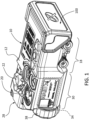
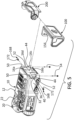
- FIGS. 1-5 , 6A , 6B , 7A, and 7B illustrate an exemplary laser accessory device comprising a laser accessory device 10 employing a first interchangeable cover assembly 100 and a second interchangeable cover assembly 200 .
- the laser accessory device 10 includes a main housing 12 .
- the main housing 12 includes a lens port 14 on a forward facing end thereof.
- the housing 12 encloses one or more laser emitters 16a , 16b , 16c , and 16d , which can be actuated to emit a laser beam toward a target via the laser lens port 14 .
- the laser emitters 16a-16d may include various combinations of aiming lasers and laser illuminators, which may emit in wavelengths within a spectrum selected from visible, infrared (IR), near infrared, short wave infrared (SWIR), ultraviolet (UV), and others.
- a rail clamp or grabber assembly 18 is provided on the housing 12 for attaching the unit 10 to a weapon accessory interface.
- the weapon is a firearm such as a military or tactical rifle, such as a Picatinny rail interface (e.g., as specified in MIL-STD-1913, STANAG 2324), or the like.
- a fire button 20 is provided to actuate the selected laser emitter(s).
- terms denoting direction or orientation such as left, right, front, rear, upper, lower, horizontal, vertical, etc., refer to the orientation of the units 10 , 100 , and 200 as they appear in the drawings, wherein the laser lens port 14 is considered to be disposed on the front of the unit 10 , the controls as described below are considered to be disposed on the top of the unit 10 , and the rail grabber assembly 18 is considered to be disposed on the bottom of the unit 10 .
- Coupled or "operatively coupled,” as used herein, is defined as indirectly or directly connected. All numbers herein are assumed to be modified by the term “about,” unless stated otherwise. The recitation of numerical ranges by endpoints includes all numbers subsumed within that range (e.g., 1 to 5 includes 1, 1.5, 2, 2.75, 3, 3.80, 4, and 5).
- the operational mode of the unit 10 is selected via a mode selection knob 22 and a keypad 24 comprising one or more buttons or keys 26a , 26b , and 26c , are provided to control various functions and parameters of the unit 10 , including laser power intensity level and others.
- a display 28 is disposed on a rearward facing end of the housing 12 to provide output to the user in human-viewable form.
- a battery compartment 30 houses one or more batteries 34 for providing electrical power for the unit 10 .
- a battery compartment cover 38 provides access to the battery compartment 30 .
- the laser accessory device may be a RAID-X (TM) aiming/illumination device available from Wilcox Industries Corp. of Newington, New Hampshire. However, it will be recognized that the modular cover system herein may be adapted for other laser accessory devices.
- the first interchangeable cover assembly 100 includes a frame 104 having a central aperture 108 aligned with the lens port 14 on the unit 10 .
- a pair of arms 112 extends from the rearward facing surface of the frame 104 on opposite transverse sides of the frame. Each of the arms 112 has a through hole 116 receiving a respective pivot pin 120 .
- the exterior or outward facing surface of each arm 112 includes a protrusion or boss 124 which is concentric with the respective opening 116 .
- Each of the arms 112 further includes a downward extending portion 128 having a generally vertical, internally threaded opening 132 .
- the arms 112 and downward extending portion 128 are received in complementary recess features 50 and 52 , respectively, on the front surface of the housing 12 to provide a secure, keyed retention of the frame 104 on the housing 12 .
- the frame 104 includes sealing members 184 along the top and bottom edges to provide a sealing interference between the frame 104 and the housing 12 to keep moisture and other environmental contamination away from the laser port 14 .
- the first interchangeable cover assembly 100 further includes a safety cover in the form of a visor 136 pivotally attached to the frame 104 .
- the visor 136 includes a front plate 140 and a pair of ears 144 extending in the rearward direction on opposite transverse sides of the front plate 140 .
- Each of the ears 144 has a transversely extending blind hole or bore 148 on the inward side thereof.
- Each bore 148 further includes a counterbore 152 disposed on an inward surface of the respective ear 144 .
- Each counterbore 152 has a diameter and depth to receive the respective boss 124 .
- Each of the ears 144 further include a curved channel or groove 156 .
- Each curved channel 156 has a first blind hole or bore 160 at a first end thereof and a second blind hole or bore 164 at a second end thereof.
- the safety cover 136 is formed of a material that blocks laser emissions. In alternative embodiments, the safety cover 136 may be formed of a material that reduces the intensity of the laser emissions to a level that is generally considered eye-safe.
- the frame is positioned between the ears 144 and the boss 124 is received within the counterbore 152 .
- the visor 136 and/or the visor frame 104 are formed of a flexible or resilient material for ease of assembly.
- the visor 136 and visor frame 104 are formed of a polymer material or a polymer/fiber composite material.
- Each pivot pin 120 is passed through the respective opening 116 and into the blind bore 148 .
- pivot stop screws 168 are removably threaded into complementary threaded openings 32 on opposite sides of the housing 12 .
- Each of the pivot stop screws 168 includes a head portion 172 which protrudes from the adjacent side surface 36 of the housing 12 .
- each opening 32 includes a counter bore 40 having a diameter and depth to receive a portion of the head portion 172 .
- the visor assembly 100 is then placed over the front end of the housing 12 until each head portion 172 is received in the respective curved channel 156 .
- the visor assembly 100 components are formed of flexible or resilient materials to allow the visor assembly 100 to flex or deform slightly to aid in positioning the head portions 172 in the grooves 156 .
- First and second threaded fasteners 54 are then passed through respective openings 44 in the housing 12 and removably engage a respective one of the threaded openings 132 on the visor frame 104 .
- each head portion 172 of the pivot stop screws 168 is received within a respective one of the first bores 160 .
- the visor 136 is pivoted upward in relation to the frame 104 about the pivot pins 120 which define a pivot axis 180 .
- the head portions 172 run in the respective curved channels 156 until the head portions engage the respective bores 164 .
- the bores 160 and 164 cooperate with the head portions 172 to provide a positive stop or detent when the visor 136 is in the deployed and stowed positions, respectively.
- the visor 136 When the visor 136 is in the open position (see FIG. 2 ), the visor plate portion 140 and ears 144 extend beyond a front surface 48 of the housing 12 . In this manner, the visor 136 acts as a rain/precipitation shield to protect the laser port from rain, snow, etc., when the unit 10 is used in the rain or other precipitation conditions.
- the protruding visor 136 also advantageously acts as a shield against off-angle viewing of the aiming and illumination beam emitters, thereby making it more difficult to pinpoint the location of the user.
- the threaded fasteners 54 are removed that the visor assembly is manually removed by disengaging the head portions 172 from the grooves 156 .
- the pivot stop screws 168 may also be removed from the housing 12 when the visor assembly 100 is not in use.
- the cover assembly 200 includes a frame 204 having a central aperture 208 aligned with the lens port 14 on the unit 10.
- a pair of arms 212 extends from the rearward facing surface of the frame 204 .
- Each of the arms 212 has a through hole or bore 216 .
- Each bore 216 includes a countersink 218 on the inward facing side thereof.
- On the outward facing side of each arm 212 there is a protruding boss 224 which is concentric with the bore 216 .
- Each boss 224 includes a keyed or noncircular (e.g., generally rectangular in the illustrated embodiment) counterbore 222 which is concentric with the bore 216 .
- the counterbore 222 receives a respective complementary noncircular post portion 226 of a pivot cap 220.
- the pivot cap 220 further includes an enlarged diameter head 230 .
- Each of the arms 212 further includes a first protrusion 214 which is complementary with the recess feature 50 on the housing 12 for providing a secure, keyed retention of the frame 204 on the housing 12 .
- Each of the arms 212 also includes a second protrusion 228 having a generally vertical, internally threaded opening 232 .
- the second protrusion 228 is received in the complementary recess feature 52 on the front surface of the housing 12 to additionally provide a secure, keyed retention of the frame 204 on the housing 12 .
- the frame 204 includes sealing members 284 along the top and bottom edges to provide a sealing interference between the frame 204 and the housing 12 to keep moisture and other environmental contamination away from the laser port 14 .
- the second interchangeable cover assembly 200 further includes a safety cover 236 pivotally attached to the frame 204 .
- the cover 236 includes a front cover panel 240 and a pair of ears 244 extending in the rearward direction on opposite transverse sides of the front panel 240 .
- the front panel 240 is complementary with and covers the laser port 14 when in the closed position.
- Each of the ears 244 has an aperture 248 configured to receive the boss 224 therein.
- the safety cover 236 is formed of a material that blocks laser emissions.
- the safety cover 236 may be formed of a material that reduces the intensity of the laser emissions to a level that is generally considered eye-safe.
- the frame 204 is positioned between the ears 244 and each boss 224 is received within a respective opening 248 .
- the frame 204 is formed of a flexible or resilient material such as a molded plastic material and the safety cover 236 is formed of a rubber or other elastomeric material, such as a natural or synthetic rubber material.
- the post 226 of each pivot cap 220 is received in the respective noncircular counterbore 222 .
- Threaded fasteners 210 pass through the holes 216 and threadably engage internal threads within a central opening 234 in the respective posts 226 .
- the fasteners 210 are flathead screws having a head portion 238 which is received in the countersink 218 so that each of the head portions 238 is flush with the inward facing surface of the respective arm 212 .
- cover assembly 200 To assemble the cover assembly 200 to the housing 12 , the cover assembly 200 is placed over the front end of the housing 12 until the protrusions 214 and 228 engage the respective complementary recesses 50 and 52 on the housing 112 . First and second threaded fasteners 54 are then passed through respective openings 44 in the housing 12 and removably engage a respective one of the threaded openings 232 on the frame 204 .
- FIG. 3 illustrates the safety cover 236 in the closed or deployed position.
- the safety cover 236 is pivoted upward in relation to the frame 204 about the pivot caps 220 , which define a pivot axis 280 .
- rotation of the pivot cap 220 is resisted because of the keyed or noncircular configuration of the post 226 and the counterbore 222 , thereby reducing the chance of inadvertently unscrewing the fasteners 210 from the pivot cap 220 .
- the threaded fasteners 54 are removed and the safety cover assembly 200 is manually removed by disengaging the protrusions 214 , 228 from the respective recesses 50 , 52 .
Landscapes
- Engineering & Computer Science (AREA)
- General Engineering & Computer Science (AREA)
- Physics & Mathematics (AREA)
- Optics & Photonics (AREA)
- Radar, Positioning & Navigation (AREA)
- General Physics & Mathematics (AREA)
- Laser Beam Processing (AREA)
- Lasers (AREA)
Description
- The present invention relates to laser accessory devices for firearms or other weapons and modular safety cover systems for such laser accessory devices.
-
US2014317988A1 discloses a weapon-mountable laser distractor having an enclosure (100) with a top surface and bottom surface connected to each other by two side surfaces, a from surface and a rear surface. The top surface includes an articulated mounting adapter (150), the bottom surface includes controls (201), the front surface includes an integral optic cover (110) and a plurality of apertures (120, 130, 140). The enclosure (100) protects and surrounds a laser device including a battery module (490) in communication with an electronic module (470). The electronic module (470) controls a plurality of light generating modules (400, 405,410) which provide light to a plurality of optic modules (420, 425, 430). A controls module (440) or remote module (460) provides instructions to the electronic module. A display module (480) and an indicator module (450) are also provided. - The present disclosure provides a laser accessory device as detailed in claim 1. Advantageous features are provided in dependent claims.
- According to the invention, a laser accessory device comprises a housing having a front side having a port, a rear side opposite the front side, a left side, a right side opposite the left side, a top side, and a bottom side opposite the top side. One or more laser emitters are disposed within the housing and are configured to emit a beam through the port. A first cover assembly is positioned on the front side and includes a first safety cover and a first frame securing the first safety cover to the housing. The first safety cover is movable between a closed position covering the port and an open position not covering the port.
- In a more limited aspect, the first safety cover juts out beyond the front side to form a visor above the port when the first safety cover is in the open position.
- In another more limited aspect, the first safety cover is stowed on the housing when the first safety cover is in the open position.
- In yet another more limited aspect, the first safety cover is stowed on the top side of the housing when the first safety cover is in the open position.
- According to the invention, the first cover assembly is removable from the housing, and the laser accessory device further comprises a second cover assembly for positioning on the front side in place of the first cover assembly. The second cover assembly includes a second safety cover and a second frame for securing the second safety cover to the housing, the second safety cover being movable between a closed position covering the port and an open position not covering the port.
- According to the invention, the first safety cover juts out beyond the front side to form a visor above the port when the first cover assembly is attached to the housing and the first safety cover is in the open position, and the second safety cover is stowed on the top side of the housing when the second cover assembly is attached to the housing and the second safety cover is in the open position.
- In yet another more limited aspect, the one or more laser emitters comprises one or more laser diodes.
- In yet another more limited aspect, the laser accessory device further comprises a power supply received within the housing and operably connected to the laser diode for energizing the one or more laser emitters.
- In yet another more limited aspect, the power supply comprises a battery disposed within a battery compartment in the housing.
- In yet another more limited aspect, the laser accessory device further comprises a battery compartment cover configured to releasably cover the battery compartment.
- In yet another more limited aspect, the bottom side comprises a clamp for coupling the laser accessory device to a weapon accessory rail.
- In yet another more limited aspect, the laser accessory device further comprises one or more activation switches on the top side which are configured to operate the one or more laser emitters.
- In yet another more limited aspect, the one or more laser emitters comprises one or more aiming lasers, one or more illumination lasers, or a combination thereof.
- In yet another more limited aspect, the one or more laser emitters includes multiple laser emitters.
- In yet another more limited aspect, each of the one or more laser emitters emits at one or more wavelengths within a spectrum selected from the group consisting of ultraviolet, visible, and infrared spectra.
- In yet another more limited aspect, the one or more laser emitters comprise one or more of a visible light laser for aiming, a visible light laser for illumination, an infrared light laser for aiming, and an infrared light laser for illumination.
- In yet another more limited aspect, the first cover assembly is configured to block laser beam emissions from the one or more laser emitters when the first safety cover is in the closed position.
- In yet another more limited aspect, the first cover assembly is configured to attenuate laser beam emission intensity from the one or more laser emitters when the first safety cover is in the closed position.
- The invention may take form in various components and arrangements of components, and in various steps and arrangements of steps. The drawings are only for purposes of illustrating preferred embodiments and are not to be construed as limiting the invention.
-
FIG. 1 is an isometric view of an exemplary laser accessory device having a first interchangeable lens cover assembly in the closed or deployed position. -
FIG. 2 is an isometric view of the laser accessory device appearing inFIG. 1 , wherein the first interchangeable lens cover assembly is in the stowed position. -
FIG. 3 is an isometric view of the laser accessory device appearing inFIGS. 1 and2 , wherein a second interchangeable lens cover assembly, shown in the deployed position, is used in place of the first interchangeable lens cover assembly. -
FIG. 4 is an isometric view of the laser accessory device configuration appearing inFIG. 3 , wherein the second interchangeable lens cover assembly is shown in the stowed position. -
FIG. 5 is a partially exploded view illustrating the modular nature of the first and second interchangeable lens cover assemblies. -
FIG. 6A is an isometric view of the first interchangeable lens cover assembly taken from the rear and side. -
FIG. 6B is an exploded, isometric view of the first interchangeable lens cover assembly taken from the rear and side. -
FIG. 7A is an isometric view of the second interchangeable lens cover assembly taken from the rear and side. -
FIG. 7B is an exploded, isometric view of the second interchangeable lens cover assembly taken from the rear and side. - Firearms and other weapon systems commonly utilize laser emitters for a number of purposes. For example, aiming lasers having one or more laser emitters bore-sighted to the barrel of a firearm or other weapon are used as weapon sights for aiming the weapon. Similarly, laser illuminators emit a beam to illuminate a target area and are often paired with aiming lasers. Laser emitters are also used to mark or designate enemy targets to pinpoint the location of enemy targets and reduce the chance that friendly forces are mistaken as an enemy target. Commonly, laser accessory devices will employ a lens cap or cover to cover the laser emitters when the unit is not in use, e.g., to keep the laser lenses clean and/or dry as well as preventing accidental laser emissions. The present development contemplates a new and improved cover system for laser accessory devices.
- Referring now to the drawings,
FIGS. 1-5 ,6A ,6B ,7A, and 7B illustrate an exemplary laser accessory device comprising alaser accessory device 10 employing a firstinterchangeable cover assembly 100 and a secondinterchangeable cover assembly 200. Thelaser accessory device 10 includes amain housing 12. Themain housing 12 includes alens port 14 on a forward facing end thereof. Thehousing 12 encloses one ormore laser emitters laser lens port 14. Thelaser emitters 16a-16d may include various combinations of aiming lasers and laser illuminators, which may emit in wavelengths within a spectrum selected from visible, infrared (IR), near infrared, short wave infrared (SWIR), ultraviolet (UV), and others. A rail clamp orgrabber assembly 18 is provided on thehousing 12 for attaching theunit 10 to a weapon accessory interface. In certain embodiments, the weapon is a firearm such as a military or tactical rifle, such as a Picatinny rail interface (e.g., as specified in MIL-STD-1913, STANAG 2324), or the like. Afire button 20 is provided to actuate the selected laser emitter(s). - As used herein, terms denoting direction or orientation, such as left, right, front, rear, upper, lower, horizontal, vertical, etc., refer to the orientation of the
units laser lens port 14 is considered to be disposed on the front of theunit 10, the controls as described below are considered to be disposed on the top of theunit 10, and therail grabber assembly 18 is considered to be disposed on the bottom of theunit 10. - The term "coupled" or "operatively coupled," as used herein, is defined as indirectly or directly connected. All numbers herein are assumed to be modified by the term "about," unless stated otherwise. The recitation of numerical ranges by endpoints includes all numbers subsumed within that range (e.g., 1 to 5 includes 1, 1.5, 2, 2.75, 3, 3.80, 4, and 5).
- In certain embodiments, the operational mode of the
unit 10 is selected via amode selection knob 22 and akeypad 24 comprising one or more buttons orkeys unit 10, including laser power intensity level and others. In certain embodiments, adisplay 28 is disposed on a rearward facing end of thehousing 12 to provide output to the user in human-viewable form. Abattery compartment 30 houses one ormore batteries 34 for providing electrical power for theunit 10. Abattery compartment cover 38 provides access to thebattery compartment 30. In certain embodiments, the laser accessory device may be a RAID-X (TM) aiming/illumination device available from Wilcox Industries Corp. of Newington, New Hampshire. However, it will be recognized that the modular cover system herein may be adapted for other laser accessory devices. - With respect to
FIGS. 1 ,2 ,6A, and 6B , the firstinterchangeable cover assembly 100 includes aframe 104 having acentral aperture 108 aligned with thelens port 14 on theunit 10. A pair ofarms 112 extends from the rearward facing surface of theframe 104 on opposite transverse sides of the frame. Each of thearms 112 has a throughhole 116 receiving arespective pivot pin 120. The exterior or outward facing surface of eacharm 112 includes a protrusion orboss 124 which is concentric with therespective opening 116. - Each of the
arms 112 further includes a downward extendingportion 128 having a generally vertical, internally threadedopening 132. Thearms 112 and downward extendingportion 128 are received in complementary recess features 50 and 52, respectively, on the front surface of thehousing 12 to provide a secure, keyed retention of theframe 104 on thehousing 12. Theframe 104 includes sealingmembers 184 along the top and bottom edges to provide a sealing interference between theframe 104 and thehousing 12 to keep moisture and other environmental contamination away from thelaser port 14. - The first
interchangeable cover assembly 100 further includes a safety cover in the form of avisor 136 pivotally attached to theframe 104. Thevisor 136 includes afront plate 140 and a pair ofears 144 extending in the rearward direction on opposite transverse sides of thefront plate 140. Each of theears 144 has a transversely extending blind hole or bore 148 on the inward side thereof. Eachbore 148, in turn, further includes acounterbore 152 disposed on an inward surface of therespective ear 144. Eachcounterbore 152 has a diameter and depth to receive therespective boss 124. Each of theears 144 further include a curved channel orgroove 156. Eachcurved channel 156, in turn, has a first blind hole or bore 160 at a first end thereof and a second blind hole or bore 164 at a second end thereof. - In certain embodiments, the
safety cover 136 is formed of a material that blocks laser emissions. In alternative embodiments, thesafety cover 136 may be formed of a material that reduces the intensity of the laser emissions to a level that is generally considered eye-safe. - To assemble the
visor 136 to thevisor frame 104, the frame is positioned between theears 144 and theboss 124 is received within thecounterbore 152. In certain embodiments, thevisor 136 and/or thevisor frame 104 are formed of a flexible or resilient material for ease of assembly. In certain embodiments, thevisor 136 andvisor frame 104 are formed of a polymer material or a polymer/fiber composite material. Eachpivot pin 120 is passed through therespective opening 116 and into theblind bore 148. - To assemble the
visor assembly 100 to thehousing 12, pivot stop screws 168 are removably threaded into complementary threadedopenings 32 on opposite sides of thehousing 12. Each of the pivot stop screws 168 includes ahead portion 172 which protrudes from theadjacent side surface 36 of thehousing 12. In certain embodiments, each opening 32 includes a counter bore 40 having a diameter and depth to receive a portion of thehead portion 172. - The
visor assembly 100 is then placed over the front end of thehousing 12 until eachhead portion 172 is received in the respectivecurved channel 156. In certain embodiments, thevisor assembly 100 components are formed of flexible or resilient materials to allow thevisor assembly 100 to flex or deform slightly to aid in positioning thehead portions 172 in thegrooves 156. First and second threadedfasteners 54 are then passed throughrespective openings 44 in thehousing 12 and removably engage a respective one of the threadedopenings 132 on thevisor frame 104. - In operation, when the
visor 136 is in the closed position (seeFIG. 1 ), eachhead portion 172 of the pivot stop screws 168 is received within a respective one of thefirst bores 160. When it is desired to open thecover assembly 100, thevisor 136 is pivoted upward in relation to theframe 104 about the pivot pins 120 which define apivot axis 180. As thevisor 136 is pivoted, thehead portions 172 run in the respectivecurved channels 156 until the head portions engage therespective bores 164. Thebores head portions 172 to provide a positive stop or detent when thevisor 136 is in the deployed and stowed positions, respectively. - When the
visor 136 is in the open position (seeFIG. 2 ), thevisor plate portion 140 andears 144 extend beyond a front surface 48 of thehousing 12. In this manner, thevisor 136 acts as a rain/precipitation shield to protect the laser port from rain, snow, etc., when theunit 10 is used in the rain or other precipitation conditions. The protrudingvisor 136 also advantageously acts as a shield against off-angle viewing of the aiming and illumination beam emitters, thereby making it more difficult to pinpoint the location of the user. - When it is desired to remove the
visor assembly 100, the threadedfasteners 54 are removed that the visor assembly is manually removed by disengaging thehead portions 172 from thegrooves 156. The pivot stop screws 168 may also be removed from thehousing 12 when thevisor assembly 100 is not in use. - With reference now to
FIGS. 3 ,4 ,7A, and 7B , thelaser accessory device 10 appears with the secondinterchangeable cover assembly 200 used in place of the firstinterchangeable cover assembly 100. Thecover assembly 200 includes aframe 204 having acentral aperture 208 aligned with thelens port 14 on theunit 10. A pair ofarms 212 extends from the rearward facing surface of theframe 204. Each of thearms 212 has a through hole or bore 216. Eachbore 216 includes acountersink 218 on the inward facing side thereof. On the outward facing side of eacharm 212, there is a protrudingboss 224 which is concentric with thebore 216. Eachboss 224 includes a keyed or noncircular (e.g., generally rectangular in the illustrated embodiment)counterbore 222 which is concentric with thebore 216. Thecounterbore 222 receives a respective complementarynoncircular post portion 226 of apivot cap 220. Thepivot cap 220 further includes anenlarged diameter head 230. - Each of the
arms 212 further includes afirst protrusion 214 which is complementary with therecess feature 50 on thehousing 12 for providing a secure, keyed retention of theframe 204 on thehousing 12. Each of thearms 212 also includes asecond protrusion 228 having a generally vertical, internally threadedopening 232. Thesecond protrusion 228 is received in thecomplementary recess feature 52 on the front surface of thehousing 12 to additionally provide a secure, keyed retention of theframe 204 on thehousing 12. Theframe 204 includes sealingmembers 284 along the top and bottom edges to provide a sealing interference between theframe 204 and thehousing 12 to keep moisture and other environmental contamination away from thelaser port 14. - The second
interchangeable cover assembly 200 further includes asafety cover 236 pivotally attached to theframe 204. Thecover 236 includes afront cover panel 240 and a pair ofears 244 extending in the rearward direction on opposite transverse sides of thefront panel 240. Thefront panel 240 is complementary with and covers thelaser port 14 when in the closed position. Each of theears 244 has anaperture 248 configured to receive theboss 224 therein. In certain embodiments, thesafety cover 236 is formed of a material that blocks laser emissions. In alternative embodiments, thesafety cover 236 may be formed of a material that reduces the intensity of the laser emissions to a level that is generally considered eye-safe. - To assemble the
safety cover 236 to theframe 204, theframe 204 is positioned between theears 244 and eachboss 224 is received within arespective opening 248. In certain embodiments, theframe 204 is formed of a flexible or resilient material such as a molded plastic material and thesafety cover 236 is formed of a rubber or other elastomeric material, such as a natural or synthetic rubber material. Thepost 226 of eachpivot cap 220 is received in therespective noncircular counterbore 222. Threadedfasteners 210 pass through theholes 216 and threadably engage internal threads within acentral opening 234 in the respective posts 226. In certain embodiments, thefasteners 210 are flathead screws having ahead portion 238 which is received in thecountersink 218 so that each of thehead portions 238 is flush with the inward facing surface of therespective arm 212. - To assemble the
cover assembly 200 to thehousing 12, thecover assembly 200 is placed over the front end of thehousing 12 until theprotrusions complementary recesses housing 112. First and second threadedfasteners 54 are then passed throughrespective openings 44 in thehousing 12 and removably engage a respective one of the threadedopenings 232 on theframe 204. -
FIG. 3 illustrates thesafety cover 236 in the closed or deployed position. When it is desired to open thecover assembly 200 to the open or stowed position as shown inFIG. 4 , thesafety cover 236 is pivoted upward in relation to theframe 204 about the pivot caps 220, which define apivot axis 280. As thecover 204 is pivoted, rotation of thepivot cap 220 is resisted because of the keyed or noncircular configuration of thepost 226 and thecounterbore 222, thereby reducing the chance of inadvertently unscrewing thefasteners 210 from thepivot cap 220. - When it is desired to remove the
safety cover assembly 200 from theunit 10, the threadedfasteners 54 are removed and thesafety cover assembly 200 is manually removed by disengaging theprotrusions respective recesses - The invention has been described with reference to the preferred embodiments. Modifications and alterations will occur to others upon a reading and understanding of the preceding detailed description. It is intended that the invention be construed as including all such modifications and alterations insofar as they come within the scope of the appended claims.
Claims (15)
- A laser accessory device (10), comprising:a housing (12) having a front side having a port (14), a rear side opposite the front side, a left side, a right side opposite the left side, a top side, and a bottom side opposite the top side;one or more laser emitters (16a, 16b, 16c, 16c) within the housing configured to emit a beam through the port;characterised in that the laser accessory device comprising a kit of first and second interchangeable cover assemblies (100, 200), each of said cover assemblies being selectively attachable and removable from the housing;the first cover assembly (100) for positioning on the front side, the first cover assembly including a first safety cover (136) and a first frame (104) securing the first safety cover to the housing, the first safety cover movable between a closed position covering the port and an open position not covering the port, the laser accessory device further comprising:the second cover (200) assembly for positioning on the front side in place of the first cover assembly, the second cover assembly including a second safety cover (236) and a second frame (204) for securing the second safety cover to the housing, the second safety cover movable between a closed position covering the port and an open position not covering the port,wherein the first safety cover (136) juts out beyond the front side to form a visor (136) above the port when the first cover assembly (100) is attached to the housing and the first safety cover is in the open position, and further wherein the second safety (200) cover is stowed on the top side of the housing when the second safety cover assembly is attached to the housing and the second safety cover is in the open position.
- The laser accessory device (10) of claim 1, wherein the first safety cover (136) is stowed on the housing when the first safety cover is in the open position.
- The laser accessory device (10) of claim 1, wherein the first safety cover (136) is stowed on the top side of the housing when the first safety cover is in the open position.
- The laser accessory device (10) of claim 1, wherein the one or more laser emitters (16a, 16b, 16c, 16c) comprises one or more laser diodes.
- The laser accessory device (10) of claim 1, further comprising a power supply received within the housing (12) and operably connected to the laser diode for energizing the one or more laser emitters (16a, 16b, 16c, 16c).
- The laser accessory device (10) of claim 5, wherein the power supply comprises a battery disposed within a battery compartment (30) in the housing.
- The laser accessory device (10) of claim 6, further comprising a battery compartment cover (38) configured to releasably cover the battery compartment (30).
- The laser accessory device (10) of claim 1, the bottom side comprising a clamp (18) for coupling the laser accessory device to a weapon accessory rail.
- The laser accessory device (10) of claim 1, further comprising one or more activation switches on the top side and configured to operate the one or more laser emitters (16a, 16b, 16c, 16c).
- The laser accessory device (10) of claim 1, wherein the one or more laser emitters (16a, 16b, 16c, 16c) comprises one or more aiming lasers, one or more illumination lasers, or a combination thereof.
- The laser accessory device (10) of claim 1, wherein the one or more laser emitters (16a, 16b, 16c, 16c) includes multiple laser emitters (16a, 16b, 16c, 16c).
- The laser accessory device (10) of claim 1, wherein each of the one or more laser emitters (16a, 16b, 16c, 16c) emits at one or more wavelengths within a spectrum selected from the group consisting of ultraviolet, visible, and infrared spectra.
- The laser accessory device (10) of claim 1, wherein the one or more laser emitters (16a, 16b, 16c, 16c) comprise one or more of:a visible light laser for aiming;a visible light laser for illumination;an infrared light laser for aiming; andan infrared light laser for illumination.
- The laser accessory device (10) of claim 1, wherein the first cover assembly (100) is configured to block laser beam emissions from the one or more laser emitters (16a, 16b, 16c, 16c) when the first safety cover is in the closed position.
- The laser accessory device (100) of claim 1, wherein the first cover assembly (100) is configured to attenuate laser beam emissions from the one or more laser emitters (16a, 16b, 16c, 16c) when the first safety cover is in the closed position.
Applications Claiming Priority (2)
| Application Number | Priority Date | Filing Date | Title |
|---|---|---|---|
| US202163179732P | 2021-04-26 | 2021-04-26 | |
| US17/706,795 US11874090B2 (en) | 2021-04-26 | 2022-03-29 | Cover system for laser accessory device |
Publications (2)
| Publication Number | Publication Date |
|---|---|
| EP4083566A1 EP4083566A1 (en) | 2022-11-02 |
| EP4083566B1 true EP4083566B1 (en) | 2024-01-31 |
Family
ID=80999744
Family Applications (1)
| Application Number | Title | Priority Date | Filing Date |
|---|---|---|---|
| EP22165464.3A Active EP4083566B1 (en) | 2021-04-26 | 2022-03-30 | Cover system for laser accessory device |
Country Status (4)
| Country | Link |
|---|---|
| US (1) | US11874090B2 (en) |
| EP (1) | EP4083566B1 (en) |
| KR (1) | KR20220147023A (en) |
| AU (1) | AU2022202249A1 (en) |
Families Citing this family (5)
| Publication number | Priority date | Publication date | Assignee | Title |
|---|---|---|---|---|
| US20220244017A1 (en) * | 2021-02-03 | 2022-08-04 | Battle Sight Technologies, LLC | Dual infrared (ir) sights for firearms |
| US12228366B2 (en) * | 2022-06-26 | 2025-02-18 | Jacob Matthew BERNAL | Tactical weapon-mounted accessory locking device, and associated methods |
| USD1082885S1 (en) * | 2023-03-21 | 2025-07-08 | Steiner Eoptics, Inc. | Aiming and illumination device |
| USD1110458S1 (en) * | 2023-03-21 | 2026-01-27 | Steiner E-Optics, Inc. | Aiming and illumination device |
| USD1079884S1 (en) * | 2023-09-11 | 2025-06-17 | Huanic Corporation | Gun sight |
Family Cites Families (8)
| Publication number | Priority date | Publication date | Assignee | Title |
|---|---|---|---|---|
| US7827726B2 (en) * | 2005-04-26 | 2010-11-09 | Tactical Devices, Inc. | Target illumination and sighting device with integrated non-lethal weaponry |
| WO2013086144A1 (en) | 2011-12-06 | 2013-06-13 | Laser Energetics, Inc. | Weapon-mountable non-lethal optical security device |
| KR101550146B1 (en) | 2014-06-20 | 2015-09-03 | 주식회사 이든이엔지 | Apparatus for protecting a sight of armoured fighting vehicle |
| AU2015333702B2 (en) * | 2014-10-13 | 2020-06-11 | Wilcox Industries Corp. | Combined Reflex And Laser Sight With Elevation Macro-Adjustment Mechanism |
| FI126108B (en) | 2015-06-25 | 2016-06-30 | Jyri Petteri Mononen | Procedure for automatically opening a protection and protection set |
| US10175029B2 (en) | 2016-01-15 | 2019-01-08 | Wilcox Industries Corp. | Combined reflex and laser sight with co-aligned iron sights |
| US10365066B2 (en) | 2016-11-16 | 2019-07-30 | Huntercraft Limited | Photoelectric sighting system and calibration method thereof |
| DE202019106217U1 (en) | 2019-11-08 | 2021-02-10 | Heinz-Eckhard Engel | Snap-on lid |
-
2022
- 2022-03-29 US US17/706,795 patent/US11874090B2/en active Active
- 2022-03-30 EP EP22165464.3A patent/EP4083566B1/en active Active
- 2022-04-04 AU AU2022202249A patent/AU2022202249A1/en active Pending
- 2022-04-14 KR KR1020220046587A patent/KR20220147023A/en active Pending
Also Published As
| Publication number | Publication date |
|---|---|
| EP4083566A1 (en) | 2022-11-02 |
| US20220341708A1 (en) | 2022-10-27 |
| AU2022202249A1 (en) | 2022-11-10 |
| KR20220147023A (en) | 2022-11-02 |
| US11874090B2 (en) | 2024-01-16 |
Similar Documents
| Publication | Publication Date | Title |
|---|---|---|
| EP4083566A1 (en) | Cover system for laser accessory device | |
| US20110047851A1 (en) | Removable foregrip with laser sight | |
| US12474142B2 (en) | Firearm laser sight alignment assembly | |
| US11965710B2 (en) | Firearm laser sight alignment assembly | |
| US10942005B2 (en) | Combined reflex and laser sight with co-aligned iron sights | |
| US5867313A (en) | Multipurpose night vision monocular | |
| US8607492B2 (en) | Modular vertical foregrip | |
| US9316460B2 (en) | One hand operational combo sight device | |
| US6363648B1 (en) | Laser aiming light for firearms | |
| EP2577213B1 (en) | Gun sight | |
| US7866083B2 (en) | Modular flashlight apparatus for firearm | |
| EP2347213B1 (en) | Optical sight | |
| US7954273B1 (en) | Weapon light | |
| EP2909566B1 (en) | Multiple laser sighting and illumination systems for firearms | |
| US20160102943A1 (en) | Combined reflex and laser sight with elevation macro-adjustment mechanism | |
| US12339098B2 (en) | Enclosed reflex sight for firearms, assembly, system and method | |
| US20240159500A1 (en) | Aiming device for firearm | |
| US20250290727A1 (en) | Riser assembly with camera assembly and weapon system employing the same | |
| EP4617614A1 (en) | Riser assembly with integral power supply and weapon system employing the same | |
| KR100669859B1 (en) | Dot-Sight Device Detachable to Rifle |
Legal Events
| Date | Code | Title | Description |
|---|---|---|---|
| PUAI | Public reference made under article 153(3) epc to a published international application that has entered the european phase |
Free format text: ORIGINAL CODE: 0009012 |
|
| STAA | Information on the status of an ep patent application or granted ep patent |
Free format text: STATUS: THE APPLICATION HAS BEEN PUBLISHED |
|
| AK | Designated contracting states |
Kind code of ref document: A1 Designated state(s): AL AT BE BG CH CY CZ DE DK EE ES FI FR GB GR HR HU IE IS IT LI LT LU LV MC MK MT NL NO PL PT RO RS SE SI SK SM TR |
|
| STAA | Information on the status of an ep patent application or granted ep patent |
Free format text: STATUS: REQUEST FOR EXAMINATION WAS MADE |
|
| 17P | Request for examination filed |
Effective date: 20230424 |
|
| RBV | Designated contracting states (corrected) |
Designated state(s): AL AT BE BG CH CY CZ DE DK EE ES FI FR GB GR HR HU IE IS IT LI LT LU LV MC MK MT NL NO PL PT RO RS SE SI SK SM TR |
|
| GRAP | Despatch of communication of intention to grant a patent |
Free format text: ORIGINAL CODE: EPIDOSNIGR1 |
|
| STAA | Information on the status of an ep patent application or granted ep patent |
Free format text: STATUS: GRANT OF PATENT IS INTENDED |
|
| INTG | Intention to grant announced |
Effective date: 20230901 |
|
| GRAS | Grant fee paid |
Free format text: ORIGINAL CODE: EPIDOSNIGR3 |
|
| GRAA | (expected) grant |
Free format text: ORIGINAL CODE: 0009210 |
|
| STAA | Information on the status of an ep patent application or granted ep patent |
Free format text: STATUS: THE PATENT HAS BEEN GRANTED |
|
| AK | Designated contracting states |
Kind code of ref document: B1 Designated state(s): AL AT BE BG CH CY CZ DE DK EE ES FI FR GB GR HR HU IE IS IT LI LT LU LV MC MK MT NL NO PL PT RO RS SE SI SK SM TR |
|
| REG | Reference to a national code |
Ref country code: GB Ref legal event code: FG4D Ref country code: CH Ref legal event code: EP |
|
| REG | Reference to a national code |
Ref country code: DE Ref legal event code: R096 Ref document number: 602022001731 Country of ref document: DE |
|
| REG | Reference to a national code |
Ref country code: IE Ref legal event code: FG4D |
|
| REG | Reference to a national code |
Ref country code: LT Ref legal event code: MG9D |
|
| REG | Reference to a national code |
Ref country code: NL Ref legal event code: MP Effective date: 20240131 |
|
| P01 | Opt-out of the competence of the unified patent court (upc) registered |
Effective date: 20240521 |
|
| PG25 | Lapsed in a contracting state [announced via postgrant information from national office to epo] |
Ref country code: IS Free format text: LAPSE BECAUSE OF FAILURE TO SUBMIT A TRANSLATION OF THE DESCRIPTION OR TO PAY THE FEE WITHIN THE PRESCRIBED TIME-LIMIT Effective date: 20240531 |
|
| PG25 | Lapsed in a contracting state [announced via postgrant information from national office to epo] |
Ref country code: LT Free format text: LAPSE BECAUSE OF FAILURE TO SUBMIT A TRANSLATION OF THE DESCRIPTION OR TO PAY THE FEE WITHIN THE PRESCRIBED TIME-LIMIT Effective date: 20240131 |
|
| PG25 | Lapsed in a contracting state [announced via postgrant information from national office to epo] |
Ref country code: GR Free format text: LAPSE BECAUSE OF FAILURE TO SUBMIT A TRANSLATION OF THE DESCRIPTION OR TO PAY THE FEE WITHIN THE PRESCRIBED TIME-LIMIT Effective date: 20240501 |
|
| REG | Reference to a national code |
Ref country code: AT Ref legal event code: MK05 Ref document number: 1654153 Country of ref document: AT Kind code of ref document: T Effective date: 20240131 |
|
| PG25 | Lapsed in a contracting state [announced via postgrant information from national office to epo] |
Ref country code: RS Free format text: LAPSE BECAUSE OF FAILURE TO SUBMIT A TRANSLATION OF THE DESCRIPTION OR TO PAY THE FEE WITHIN THE PRESCRIBED TIME-LIMIT Effective date: 20240430 Ref country code: HR Free format text: LAPSE BECAUSE OF FAILURE TO SUBMIT A TRANSLATION OF THE DESCRIPTION OR TO PAY THE FEE WITHIN THE PRESCRIBED TIME-LIMIT Effective date: 20240131 Ref country code: NL Free format text: LAPSE BECAUSE OF FAILURE TO SUBMIT A TRANSLATION OF THE DESCRIPTION OR TO PAY THE FEE WITHIN THE PRESCRIBED TIME-LIMIT Effective date: 20240131 |
|
| PG25 | Lapsed in a contracting state [announced via postgrant information from national office to epo] |
Ref country code: ES Free format text: LAPSE BECAUSE OF FAILURE TO SUBMIT A TRANSLATION OF THE DESCRIPTION OR TO PAY THE FEE WITHIN THE PRESCRIBED TIME-LIMIT Effective date: 20240131 |
|
| PG25 | Lapsed in a contracting state [announced via postgrant information from national office to epo] |
Ref country code: AT Free format text: LAPSE BECAUSE OF FAILURE TO SUBMIT A TRANSLATION OF THE DESCRIPTION OR TO PAY THE FEE WITHIN THE PRESCRIBED TIME-LIMIT Effective date: 20240131 |
|
| PG25 | Lapsed in a contracting state [announced via postgrant information from national office to epo] |
Ref country code: RS Free format text: LAPSE BECAUSE OF FAILURE TO SUBMIT A TRANSLATION OF THE DESCRIPTION OR TO PAY THE FEE WITHIN THE PRESCRIBED TIME-LIMIT Effective date: 20240430 Ref country code: NO Free format text: LAPSE BECAUSE OF FAILURE TO SUBMIT A TRANSLATION OF THE DESCRIPTION OR TO PAY THE FEE WITHIN THE PRESCRIBED TIME-LIMIT Effective date: 20240430 Ref country code: NL Free format text: LAPSE BECAUSE OF FAILURE TO SUBMIT A TRANSLATION OF THE DESCRIPTION OR TO PAY THE FEE WITHIN THE PRESCRIBED TIME-LIMIT Effective date: 20240131 Ref country code: LT Free format text: LAPSE BECAUSE OF FAILURE TO SUBMIT A TRANSLATION OF THE DESCRIPTION OR TO PAY THE FEE WITHIN THE PRESCRIBED TIME-LIMIT Effective date: 20240131 Ref country code: IS Free format text: LAPSE BECAUSE OF FAILURE TO SUBMIT A TRANSLATION OF THE DESCRIPTION OR TO PAY THE FEE WITHIN THE PRESCRIBED TIME-LIMIT Effective date: 20240531 Ref country code: HR Free format text: LAPSE BECAUSE OF FAILURE TO SUBMIT A TRANSLATION OF THE DESCRIPTION OR TO PAY THE FEE WITHIN THE PRESCRIBED TIME-LIMIT Effective date: 20240131 Ref country code: GR Free format text: LAPSE BECAUSE OF FAILURE TO SUBMIT A TRANSLATION OF THE DESCRIPTION OR TO PAY THE FEE WITHIN THE PRESCRIBED TIME-LIMIT Effective date: 20240501 Ref country code: FI Free format text: LAPSE BECAUSE OF FAILURE TO SUBMIT A TRANSLATION OF THE DESCRIPTION OR TO PAY THE FEE WITHIN THE PRESCRIBED TIME-LIMIT Effective date: 20240131 Ref country code: ES Free format text: LAPSE BECAUSE OF FAILURE TO SUBMIT A TRANSLATION OF THE DESCRIPTION OR TO PAY THE FEE WITHIN THE PRESCRIBED TIME-LIMIT Effective date: 20240131 Ref country code: BG Free format text: LAPSE BECAUSE OF FAILURE TO SUBMIT A TRANSLATION OF THE DESCRIPTION OR TO PAY THE FEE WITHIN THE PRESCRIBED TIME-LIMIT Effective date: 20240131 Ref country code: AT Free format text: LAPSE BECAUSE OF FAILURE TO SUBMIT A TRANSLATION OF THE DESCRIPTION OR TO PAY THE FEE WITHIN THE PRESCRIBED TIME-LIMIT Effective date: 20240131 |
|
| PG25 | Lapsed in a contracting state [announced via postgrant information from national office to epo] |
Ref country code: PL Free format text: LAPSE BECAUSE OF FAILURE TO SUBMIT A TRANSLATION OF THE DESCRIPTION OR TO PAY THE FEE WITHIN THE PRESCRIBED TIME-LIMIT Effective date: 20240131 Ref country code: PT Free format text: LAPSE BECAUSE OF FAILURE TO SUBMIT A TRANSLATION OF THE DESCRIPTION OR TO PAY THE FEE WITHIN THE PRESCRIBED TIME-LIMIT Effective date: 20240531 |
|
| PG25 | Lapsed in a contracting state [announced via postgrant information from national office to epo] |
Ref country code: SE Free format text: LAPSE BECAUSE OF FAILURE TO SUBMIT A TRANSLATION OF THE DESCRIPTION OR TO PAY THE FEE WITHIN THE PRESCRIBED TIME-LIMIT Effective date: 20240131 Ref country code: PT Free format text: LAPSE BECAUSE OF FAILURE TO SUBMIT A TRANSLATION OF THE DESCRIPTION OR TO PAY THE FEE WITHIN THE PRESCRIBED TIME-LIMIT Effective date: 20240531 Ref country code: PL Free format text: LAPSE BECAUSE OF FAILURE TO SUBMIT A TRANSLATION OF THE DESCRIPTION OR TO PAY THE FEE WITHIN THE PRESCRIBED TIME-LIMIT Effective date: 20240131 Ref country code: LV Free format text: LAPSE BECAUSE OF FAILURE TO SUBMIT A TRANSLATION OF THE DESCRIPTION OR TO PAY THE FEE WITHIN THE PRESCRIBED TIME-LIMIT Effective date: 20240131 |
|
| PG25 | Lapsed in a contracting state [announced via postgrant information from national office to epo] |
Ref country code: DK Free format text: LAPSE BECAUSE OF FAILURE TO SUBMIT A TRANSLATION OF THE DESCRIPTION OR TO PAY THE FEE WITHIN THE PRESCRIBED TIME-LIMIT Effective date: 20240131 |
|
| PG25 | Lapsed in a contracting state [announced via postgrant information from national office to epo] |
Ref country code: SM Free format text: LAPSE BECAUSE OF FAILURE TO SUBMIT A TRANSLATION OF THE DESCRIPTION OR TO PAY THE FEE WITHIN THE PRESCRIBED TIME-LIMIT Effective date: 20240131 |
|
| PG25 | Lapsed in a contracting state [announced via postgrant information from national office to epo] |
Ref country code: EE Free format text: LAPSE BECAUSE OF FAILURE TO SUBMIT A TRANSLATION OF THE DESCRIPTION OR TO PAY THE FEE WITHIN THE PRESCRIBED TIME-LIMIT Effective date: 20240131 Ref country code: CZ Free format text: LAPSE BECAUSE OF FAILURE TO SUBMIT A TRANSLATION OF THE DESCRIPTION OR TO PAY THE FEE WITHIN THE PRESCRIBED TIME-LIMIT Effective date: 20240131 |
|
| PG25 | Lapsed in a contracting state [announced via postgrant information from national office to epo] |
Ref country code: SK Free format text: LAPSE BECAUSE OF FAILURE TO SUBMIT A TRANSLATION OF THE DESCRIPTION OR TO PAY THE FEE WITHIN THE PRESCRIBED TIME-LIMIT Effective date: 20240131 |
|
| PG25 | Lapsed in a contracting state [announced via postgrant information from national office to epo] |
Ref country code: SM Free format text: LAPSE BECAUSE OF FAILURE TO SUBMIT A TRANSLATION OF THE DESCRIPTION OR TO PAY THE FEE WITHIN THE PRESCRIBED TIME-LIMIT Effective date: 20240131 Ref country code: SK Free format text: LAPSE BECAUSE OF FAILURE TO SUBMIT A TRANSLATION OF THE DESCRIPTION OR TO PAY THE FEE WITHIN THE PRESCRIBED TIME-LIMIT Effective date: 20240131 Ref country code: RO Free format text: LAPSE BECAUSE OF FAILURE TO SUBMIT A TRANSLATION OF THE DESCRIPTION OR TO PAY THE FEE WITHIN THE PRESCRIBED TIME-LIMIT Effective date: 20240131 Ref country code: EE Free format text: LAPSE BECAUSE OF FAILURE TO SUBMIT A TRANSLATION OF THE DESCRIPTION OR TO PAY THE FEE WITHIN THE PRESCRIBED TIME-LIMIT Effective date: 20240131 Ref country code: DK Free format text: LAPSE BECAUSE OF FAILURE TO SUBMIT A TRANSLATION OF THE DESCRIPTION OR TO PAY THE FEE WITHIN THE PRESCRIBED TIME-LIMIT Effective date: 20240131 Ref country code: CZ Free format text: LAPSE BECAUSE OF FAILURE TO SUBMIT A TRANSLATION OF THE DESCRIPTION OR TO PAY THE FEE WITHIN THE PRESCRIBED TIME-LIMIT Effective date: 20240131 |
|
| REG | Reference to a national code |
Ref country code: DE Ref legal event code: R097 Ref document number: 602022001731 Country of ref document: DE |
|
| PG25 | Lapsed in a contracting state [announced via postgrant information from national office to epo] |
Ref country code: LU Free format text: LAPSE BECAUSE OF NON-PAYMENT OF DUE FEES Effective date: 20240330 |
|
| PG25 | Lapsed in a contracting state [announced via postgrant information from national office to epo] |
Ref country code: MC Free format text: LAPSE BECAUSE OF FAILURE TO SUBMIT A TRANSLATION OF THE DESCRIPTION OR TO PAY THE FEE WITHIN THE PRESCRIBED TIME-LIMIT Effective date: 20240131 |
|
| PG25 | Lapsed in a contracting state [announced via postgrant information from national office to epo] |
Ref country code: MC Free format text: LAPSE BECAUSE OF FAILURE TO SUBMIT A TRANSLATION OF THE DESCRIPTION OR TO PAY THE FEE WITHIN THE PRESCRIBED TIME-LIMIT Effective date: 20240131 Ref country code: LU Free format text: LAPSE BECAUSE OF NON-PAYMENT OF DUE FEES Effective date: 20240330 |
|
| PG25 | Lapsed in a contracting state [announced via postgrant information from national office to epo] |
Ref country code: IT Free format text: LAPSE BECAUSE OF FAILURE TO SUBMIT A TRANSLATION OF THE DESCRIPTION OR TO PAY THE FEE WITHIN THE PRESCRIBED TIME-LIMIT Effective date: 20240131 |
|
| PLBE | No opposition filed within time limit |
Free format text: ORIGINAL CODE: 0009261 |
|
| STAA | Information on the status of an ep patent application or granted ep patent |
Free format text: STATUS: NO OPPOSITION FILED WITHIN TIME LIMIT |
|
| REG | Reference to a national code |
Ref country code: BE Ref legal event code: MM Effective date: 20240331 |
|
| PG25 | Lapsed in a contracting state [announced via postgrant information from national office to epo] |
Ref country code: IT Free format text: LAPSE BECAUSE OF FAILURE TO SUBMIT A TRANSLATION OF THE DESCRIPTION OR TO PAY THE FEE WITHIN THE PRESCRIBED TIME-LIMIT Effective date: 20240131 |
|
| 26N | No opposition filed |
Effective date: 20241101 |
|
| PG25 | Lapsed in a contracting state [announced via postgrant information from national office to epo] |
Ref country code: BE Free format text: LAPSE BECAUSE OF NON-PAYMENT OF DUE FEES Effective date: 20240331 |
|
| PG25 | Lapsed in a contracting state [announced via postgrant information from national office to epo] |
Ref country code: IE Free format text: LAPSE BECAUSE OF NON-PAYMENT OF DUE FEES Effective date: 20240330 |
|
| PG25 | Lapsed in a contracting state [announced via postgrant information from national office to epo] |
Ref country code: IE Free format text: LAPSE BECAUSE OF NON-PAYMENT OF DUE FEES Effective date: 20240330 Ref country code: BE Free format text: LAPSE BECAUSE OF NON-PAYMENT OF DUE FEES Effective date: 20240331 |
|
| PG25 | Lapsed in a contracting state [announced via postgrant information from national office to epo] |
Ref country code: SI Free format text: LAPSE BECAUSE OF FAILURE TO SUBMIT A TRANSLATION OF THE DESCRIPTION OR TO PAY THE FEE WITHIN THE PRESCRIBED TIME-LIMIT Effective date: 20240131 |
|
| PG25 | Lapsed in a contracting state [announced via postgrant information from national office to epo] |
Ref country code: CY Free format text: LAPSE BECAUSE OF FAILURE TO SUBMIT A TRANSLATION OF THE DESCRIPTION OR TO PAY THE FEE WITHIN THE PRESCRIBED TIME-LIMIT; INVALID AB INITIO Effective date: 20220330 |
|
| REG | Reference to a national code |
Ref country code: CH Ref legal event code: H13 Free format text: ST27 STATUS EVENT CODE: U-0-0-H10-H13 (AS PROVIDED BY THE NATIONAL OFFICE) Effective date: 20251023 |
|
| PG25 | Lapsed in a contracting state [announced via postgrant information from national office to epo] |
Ref country code: TR Free format text: LAPSE BECAUSE OF FAILURE TO SUBMIT A TRANSLATION OF THE DESCRIPTION OR TO PAY THE FEE WITHIN THE PRESCRIBED TIME-LIMIT Effective date: 20240131 |
|
| PG25 | Lapsed in a contracting state [announced via postgrant information from national office to epo] |
Ref country code: CH Free format text: LAPSE BECAUSE OF NON-PAYMENT OF DUE FEES Effective date: 20250331 |
|
| PGFP | Annual fee paid to national office [announced via postgrant information from national office to epo] |
Ref country code: GB Payment date: 20260327 Year of fee payment: 5 |
|
| PGFP | Annual fee paid to national office [announced via postgrant information from national office to epo] |
Ref country code: DE Payment date: 20260327 Year of fee payment: 5 |
|
| PGFP | Annual fee paid to national office [announced via postgrant information from national office to epo] |
Ref country code: FR Payment date: 20260325 Year of fee payment: 5 |