EP4083562A1 - Loop heat pipe - Google Patents
Loop heat pipe Download PDFInfo
- Publication number
- EP4083562A1 EP4083562A1 EP22169484.7A EP22169484A EP4083562A1 EP 4083562 A1 EP4083562 A1 EP 4083562A1 EP 22169484 A EP22169484 A EP 22169484A EP 4083562 A1 EP4083562 A1 EP 4083562A1
- Authority
- EP
- European Patent Office
- Prior art keywords
- metal layer
- convex portion
- bottomed hole
- face
- heat pipe
- Prior art date
- Legal status (The legal status is an assumption and is not a legal conclusion. Google has not performed a legal analysis and makes no representation as to the accuracy of the status listed.)
- Granted
Links
Images





Classifications
-
- F—MECHANICAL ENGINEERING; LIGHTING; HEATING; WEAPONS; BLASTING
- F28—HEAT EXCHANGE IN GENERAL
- F28D—HEAT-EXCHANGE APPARATUS, NOT PROVIDED FOR IN ANOTHER SUBCLASS, IN WHICH THE HEAT-EXCHANGE MEDIA DO NOT COME INTO DIRECT CONTACT
- F28D15/00—Heat-exchange apparatus with the intermediate heat-transfer medium in closed tubes passing into or through the conduit walls ; Heat-exchange apparatus employing intermediate heat-transfer medium or bodies
- F28D15/02—Heat-exchange apparatus with the intermediate heat-transfer medium in closed tubes passing into or through the conduit walls ; Heat-exchange apparatus employing intermediate heat-transfer medium or bodies in which the medium condenses and evaporates, e.g. heat pipes
- F28D15/04—Heat-exchange apparatus with the intermediate heat-transfer medium in closed tubes passing into or through the conduit walls ; Heat-exchange apparatus employing intermediate heat-transfer medium or bodies in which the medium condenses and evaporates, e.g. heat pipes with tubes having a capillary structure
- F28D15/043—Heat-exchange apparatus with the intermediate heat-transfer medium in closed tubes passing into or through the conduit walls ; Heat-exchange apparatus employing intermediate heat-transfer medium or bodies in which the medium condenses and evaporates, e.g. heat pipes with tubes having a capillary structure forming loops, e.g. capillary pumped loops
-
- F—MECHANICAL ENGINEERING; LIGHTING; HEATING; WEAPONS; BLASTING
- F28—HEAT EXCHANGE IN GENERAL
- F28D—HEAT-EXCHANGE APPARATUS, NOT PROVIDED FOR IN ANOTHER SUBCLASS, IN WHICH THE HEAT-EXCHANGE MEDIA DO NOT COME INTO DIRECT CONTACT
- F28D15/00—Heat-exchange apparatus with the intermediate heat-transfer medium in closed tubes passing into or through the conduit walls ; Heat-exchange apparatus employing intermediate heat-transfer medium or bodies
- F28D15/02—Heat-exchange apparatus with the intermediate heat-transfer medium in closed tubes passing into or through the conduit walls ; Heat-exchange apparatus employing intermediate heat-transfer medium or bodies in which the medium condenses and evaporates, e.g. heat pipes
- F28D15/0275—Arrangements for coupling heat-pipes together or with other structures, e.g. with base blocks; Heat pipe cores
-
- F—MECHANICAL ENGINEERING; LIGHTING; HEATING; WEAPONS; BLASTING
- F28—HEAT EXCHANGE IN GENERAL
- F28D—HEAT-EXCHANGE APPARATUS, NOT PROVIDED FOR IN ANOTHER SUBCLASS, IN WHICH THE HEAT-EXCHANGE MEDIA DO NOT COME INTO DIRECT CONTACT
- F28D15/00—Heat-exchange apparatus with the intermediate heat-transfer medium in closed tubes passing into or through the conduit walls ; Heat-exchange apparatus employing intermediate heat-transfer medium or bodies
- F28D15/02—Heat-exchange apparatus with the intermediate heat-transfer medium in closed tubes passing into or through the conduit walls ; Heat-exchange apparatus employing intermediate heat-transfer medium or bodies in which the medium condenses and evaporates, e.g. heat pipes
- F28D15/04—Heat-exchange apparatus with the intermediate heat-transfer medium in closed tubes passing into or through the conduit walls ; Heat-exchange apparatus employing intermediate heat-transfer medium or bodies in which the medium condenses and evaporates, e.g. heat pipes with tubes having a capillary structure
- F28D15/046—Heat-exchange apparatus with the intermediate heat-transfer medium in closed tubes passing into or through the conduit walls ; Heat-exchange apparatus employing intermediate heat-transfer medium or bodies in which the medium condenses and evaporates, e.g. heat pipes with tubes having a capillary structure characterised by the material or the construction of the capillary structure
-
- F—MECHANICAL ENGINEERING; LIGHTING; HEATING; WEAPONS; BLASTING
- F28—HEAT EXCHANGE IN GENERAL
- F28F—DETAILS OF HEAT-EXCHANGE AND HEAT-TRANSFER APPARATUS, OF GENERAL APPLICATION
- F28F21/00—Constructions of heat-exchange apparatus characterised by the selection of particular materials
- F28F21/08—Constructions of heat-exchange apparatus characterised by the selection of particular materials of metal
-
- F—MECHANICAL ENGINEERING; LIGHTING; HEATING; WEAPONS; BLASTING
- F28—HEAT EXCHANGE IN GENERAL
- F28F—DETAILS OF HEAT-EXCHANGE AND HEAT-TRANSFER APPARATUS, OF GENERAL APPLICATION
- F28F3/00—Plate-like or laminated elements; Assemblies of plate-like or laminated elements
- F28F3/02—Elements or assemblies thereof with means for increasing heat-transfer area, e.g. with fins, with recesses, with corrugations
- F28F3/04—Elements or assemblies thereof with means for increasing heat-transfer area, e.g. with fins, with recesses, with corrugations the means being integral with the element
- F28F3/048—Elements or assemblies thereof with means for increasing heat-transfer area, e.g. with fins, with recesses, with corrugations the means being integral with the element in the form of ribs integral with the element or local variations in thickness of the element, e.g. grooves, microchannels
-
- G—PHYSICS
- G06—COMPUTING OR CALCULATING; COUNTING
- G06F—ELECTRIC DIGITAL DATA PROCESSING
- G06F1/00—Details not covered by groups G06F3/00 - G06F13/00 and G06F21/00
- G06F1/16—Constructional details or arrangements
- G06F1/20—Cooling means
-
- F—MECHANICAL ENGINEERING; LIGHTING; HEATING; WEAPONS; BLASTING
- F28—HEAT EXCHANGE IN GENERAL
- F28F—DETAILS OF HEAT-EXCHANGE AND HEAT-TRANSFER APPARATUS, OF GENERAL APPLICATION
- F28F2275/00—Fastening; Joining
- F28F2275/06—Fastening; Joining by welding
- F28F2275/061—Fastening; Joining by welding by diffusion bonding
Definitions
- the present invention relates to a loop heat pipe.
- a heat pipe configured to transport heat by utilizing a phase change of a working fluid is suggested (for example, refer to Japanese Patent No. 6,291,000 and Japanese Patent No. 6,400,240 ).
- a loop heat pipe including an evaporator configured to vaporize a working fluid by heat of a heat-generating component and a condenser configured to cool and condense the vaporized working fluid, wherein the evaporator and the condenser are connected by a liquid pipe and a vapor pipe configured to form a loop-like flow channel.
- the working fluid flows in one direction in the loop-like flow channel.
- the flow channel is formed by laminating a plurality of metal layers.
- the plurality of metal layers has a pair of outer metal layers provided at both ends in a laminating direction of the plurality of metal layers, and a plurality of inner metal layers provided between the pair of outer metal layers.
- the plurality of inner metal layers is provided with a porous body having a fine pore formed by partially communicating a bottomed hole recessed from one face of each inner metal layer and a bottomed hole recessed from the other face of each inner metal layer.
- One end-side of the inner metal layer in the laminating direction is bonded to one outer metal layer, and the other end-side of the inner metal layer in the laminating direction is bonded to the other outer metal layer.
- volume expansion may occur when the working fluid of a liquid phase is vaporized, depending on a characteristic of the working fluid sealed in the flow channel. Further, in the loop heat pipe, when an ambient temperature of the loop heat pipe becomes lower than a freezing point of the working fluid, the working fluid freezes and solidifies. At this time, volume expansion may occur as the working fluid undergoes a phase change from a liquid phase to a solid phase. When such volume expansion occurs, the outer metal layer is deformed to bulge outward, so that the outer metal layer may be peeled off from the inner metal layer.
- Certain embodiment provides a loop heat pipe.
- the loop heat pipe comprises:
- a loop heat pipe 10 shown in FIG. 1 is accommodated in a mobile electronic device M1 such as a smart phone and a tablet terminal.
- the loop heat pipe 10 has an evaporator 11, a vapor pipe 12, a condenser 13, and a liquid pipe 14.
- the evaporator 11 and the condenser 13 are connected by the vapor pipe 12 and the liquid pipe 14.
- the evaporator 11 has a function of vaporizing a working fluid C to generate steam Cv.
- the steam Cv generated in the evaporator 11 is sent to the condenser 13 via the vapor pipe 12.
- the condenser 13 has a function of condensing the steam Cv of the working fluid C.
- the liquefied working fluid C is sent to the evaporator 11 via the liquid pipe 14.
- the vapor pipe 12 and the liquid pipe 14 are configured to form a loop-like flow channel 15 through which the working fluid C or the steam Cv is caused to flow.
- the vapor pipe 12 is formed, for example, by an elongated pipe body.
- the liquid pipe 14 is formed, for example, by an elongated pipe body.
- the vapor pipe 12 and the liquid pipe 14 are the same in dimension (i.e., length) in a length direction, for example.
- the length of the vapor pipe 12 and the length of the liquid pipe 14 may also be different from each other.
- the length of the vapor pipe 12 may also be shorter than the length of the liquid pipe 14.
- the 'length direction' of the evaporator 11, the vapor pipe 12, the condenser 13 and the liquid pipe 14 is a direction that coincides with a direction (refer to an arrow in the drawing) in which the working fluid C or steam Cv flows in each member.
- the evaporator 11 is closely fixed to a heat-generating component (not shown).
- the working fluid C in the evaporator 11 is vaporized by heat generated by the heat-generating component, and steam Cv is accordingly generated.
- a thermal conduction member (TIM: Thermal Interface Material) may also be interposed between the evaporator 11 and the heat-generating component.
- the thermal conduction member is configured to reduce a contact thermal resistance between the heat-generating component and the evaporator 11 and to smooth heat conduction from the heat-generating component to the evaporator 11.
- the evaporator 12 has a pair of pipe walls 12w provided on both sides in a width direction orthogonal to the length direction of the evaporator 12, in plan view, and a flow channel 12r provided between the pair of pipe walls 12w, for example.
- the flow channel 12r is formed to communicate with an internal space of the evaporator 11.
- the flow channel 12r is a part of the loop-like flow channel 15.
- the steam Cv generated in the evaporator 11 is introduced into the condenser 13 via the vapor pipe 12.
- the condenser 13 has a heat radiation plate 13p whose area is increased for heat radiation, and a serpentine flow channel 13r in the heat radiation plate 13p, for example.
- the flow channel 13r is a part of the loop-like flow channel 15.
- the steam Cv introduced via the vapor pipe 12 is liquefied in the condenser33.
- the liquid pipe 14 has a pair of pipe walls 14w provided on both sides in the width direction orthogonal to the length direction of the liquid pipe 14, in plan view, and a flow channel 14r provided between the pair of pipe walls 14w, for example.
- the flow channel 14r is formed to communicate with the flow channel 13r of the condenser 13 and the internal space of the evaporator 11.
- the flow channel 14r is a part of the loop-like flow channel 15.
- the liquid pipe 14 has a porous body 20.
- the porous body 20 is formed to extend from the condenser 13 to the evaporator 11 along the length direction of the liquid pipe 14, for example.
- the porous body 20 is configured to guide the working fluid C liquefied in the condenser 13 to the evaporator 11 by a capillary force generated in the porous body 20. That is, the working fluid C liquefied in the condenser 13 is guided to the evaporator 11 through the liquid pipe 14.
- a porous body similar to the porous body 20 is also provided in the evaporator 11.
- the heat generated by the heat-generating component is transferred to the condenser 13 and radiated by the condenser 13. Thereby, the heat-generating component is cooled, and the temperature rise of the heat-generating component is suppressed.
- the working fluid C a fluid having a high vapor pressure and a high latent heat of vaporization is preferably used. By using such working fluid C, it is possible to effectively cool the heat-generating component by the latent heat of vaporization.
- the working fluid C ammonia, water, freon, alcohol, acetone and the like can be used, for example.
- FIG. 2A shows a section of the liquid pipe 14 taken along a line 2-2 of FIG. 1 .
- the section is a face orthogonal to a direction (direction denoted with an arrow in FIG. 1 ) in which the working fluid C flows in the liquid pipe 14.
- FIG. 2B is an enlarged sectional view of a part of the liquid pipe 14 shown in FIG. 2A .
- the liquid pipe 14 has a structure where metal layers 31, 32 and 33 of three layers, for example, are laminated.
- the liquid pipe 14 has a structure where the metal layer 32, which is an inner metal layer, is laminated between the metal layers 31 and 33, which are a pair of outer metal layers.
- the inner metal layer of the liquid pipe 14 of the present embodiment is configured by only one metal layer 32.
- Each of the metal layers 31 to 33 is a copper (Cu) layer having excellent thermal conductivity.
- the plurality of metal layers 31 to 33 is directly bonded to each other by solid-phase bonding such as diffusion joining, pressure welding, friction pressure welding and ultrasonic joining. Note that, in FIG. 2 , the metal layers 31 to 33 are identified by solid lines for easy understanding. For example, when the metal layers 31 to 33 are integrated by diffusion joining, interfaces of the respective metal layers 31 to 33 may be lost and boundaries may not be clear, in some cases.
- the solid-phase bonding is a method of heating and softening joining targets in a solid-phase (solid) state without melting the same, and then further heating, plastically deforming and joining the joining targets.
- the metal layers 31 to 33 are not limited to the copper layers and may also be formed of stainless steel, aluminum, magnesium alloy or the like. In addition, for some of the laminated metal layers 31 to 33, a material different from the other metal layers may also be used. A thickness of each of the metal layers 31 to 33 may be set to about 50 ⁇ m to 200 ⁇ m, for example. Note that, some of the metal layers 31 to 33 may be formed to have a thickness different from the other metal layers, and all the metal layers may be formed to have thicknesses different from each other.
- the liquid pipe 14 is configured by the laminated metal layers 31 to 33, and has a pair of pipe walls 14w provided at both ends in a width direction (a right and left direction in FIG. 2A ) of the liquid pipe 14 orthogonal to the laminating direction of the metal layers 31 to 33, and a porous body 20 provided between the pair of pipe walls 14w.
- the porous body 20 is formed to be continuous with, for example, the pipe walls 14w.
- the metal layer 31 is laminated on an upper face of the metal layer 32.
- a lower face of the metal layer 31 is formed with one or more grooves 31g.
- Each groove 31g is formed to be recessed from the lower face of the metal layer 31 to a central portion in a thickness direction of the metal layer 31.
- the metal layer 32 is laminated between the metal layer 31 and the metal layer 33.
- the upper face (e.g. a first face) of the metal layer 32 is bonded to the lower face of the metal layer 31.
- a lower face (e.g. a second face) of the metal layer 32 is bonded to an upper face of the metal layer 33.
- the metal layer 32 has a pair of wall portions 32w provided at both ends in the width direction of the liquid pipe 14 and a porous body 32s provided between the pair of wall portions 32w.
- the metal layer 33 is laminated on the lower face of the metal layer 32.
- the upper face of the metal layer 33 is formed with one or more grooves 33g.
- Each groove 33g is formed to be recessed from the upper face of the metal layer 33 to a central portion in a thickness direction of the metal layer 33.
- the pipe wall 14w is configured by, for example, a wall portion 32w of the metal layer 32 that is an inner metal layer.
- Each pipe wall 14w of the present embodiment is configured by only the wall portion 32w.
- Each wall portion 32w is not formed with a hole or a groove.
- the porous body 20 has, for example, the porous body 32s of the metal layer 32, which is the inner metal layer, and the grooves 31g and 33g of the metal layers 31 and 33, which are the outer metal layers.
- the porous body 32s has a bottomed hole 40 recessed from the upper face of the metal layer 32 to the central portion in the thickness direction of the metal layer 32, and a bottomed hole 50 recessed from the lower face of the metal layer 32 to the central portion in the thickness direction of the metal layer 32.
- the porous body 32s has a pore 60 formed by partially communicating the bottomed hole 40 and the bottomed hole 50.
- the size, such as the diameter, of the pore 60 may be smaller than the size, such as taken in plan view, of each of the bottomed holes 40 and 50.
- a depth of each of the bottomed holes 40 and 50 may be set to about 25 ⁇ m to 100 ⁇ m, for example.
- an inner face of each of the bottomed holes 40 and 50 is formed in a shape continuing in an arc shape from an opening-side (upper and lower faces-side of the metal layer 32) to a bottom face, for example.
- the inner face of each of the bottomed holes 40 and 50 is formed to have a curved face curved in an arc shape in a sectional view.
- the sectional shape of each of the inner faces of the bottomed holes 40 and 50 is formed, for example, in a curved face curved in an arc shape so that an opening width in the middle of the bottomed holes 40 and 50 in a depth direction is widest.
- each of the bottomed holes 40 and 50 is formed in a curved face curved in an arc shape in a sectional view.
- the bottom face of each of the bottomed holes 40 and 50 is formed to be continuous with the inner face of each of the bottomed holes 40 and 50, for example.
- a radius of curvature of the bottom face of each of the bottomed holes 40 and 50 may be the same as a radius of curvature of the inner face of each of the bottomed holes 40 and 50, or may be different from the radius of curvature of the inner face of each of the bottomed holes 40 and 50.
- the 'same' includes not only a case where comparison targets are exactly the same but also a case where there is a slight difference between the comparison targets due to influences of dimensional tolerances and the like.
- each of the bottomed holes 40 and 50 may be formed in a concave shape having a semi-circular or semi-elliptical sectional shape.
- the 'semi-circular shape' includes not only a semicircle obtained by bisecting a true circle, but also, for example, one having an arc longer or shorter than the semicircle.
- the 'semi-elliptical shape' includes not only a semi-ellipse obtained by bisecting an ellipse, but also, for example, one having an arc longer or shorter than the semi-ellipse.
- each of the bottomed holes 40 and 50 may be formed in a tapered shape that expands from the bottom face toward the opening-side. Further, the bottom face of each of the bottomed holes 40 and 50 may be formed to be a plane parallel to the upper face of the metal layer 32, and the inner side face of each of the bottomed holes 40 and 50 may be formed to extend perpendicularly to the bottom face.
- the bottomed holes 40 and 50 are each formed in a circular shape in plan view, for example.
- a diameter of each of the bottomed holes 40 and 50 may be set to about 100 ⁇ m to 400 ⁇ m, for example.
- the planar shape of each of the bottomed holes 40 and 50 can be formed in an arbitrary shape such as an ellipse or a polygon.
- the bottomed hole 40 and the bottomed hole 50 partially overlap in plan view. In the portion where the bottomed hole 40 and the bottomed hole 50 overlap in plan view, the bottomed hole 40 and the bottomed hole 50 partially communicate with each other to form the pore 60.
- FIG. 3 shows only the portion of the metal layer 32, which constitutes the porous body 32s (the bottomed holes 40 and 50 and the pores 60).
- the bottomed hole 40 has therein a convex portion 41. That is, the metal layer 32 has a convex portion 41 provided in the bottomed hole 40.
- the convex portion 41 is formed continuously and integrally with the metal layer 32 constituting the bottom face of the bottomed hole 40, for example.
- the convex portion 41 is provided, for example, apart from an entire circumference of the inner face of the bottomed hole 40. That is, a space is formed over the entire circumference of the bottomed hole 40 between an outer circumferential face of the convex portion 41 and the inner face of the bottomed hole 40.
- the convex portion 41 is provided at a central portion of the bottomed hole 40, in plan view.
- the convex portion 41 of the present embodiment is provided at a center of the bottomed hole 40, in plan view.
- the convex portion 41 is provided, for example, at a position that does not overlap the entire bottomed hole 50, in plan view.
- a planar shape of the convex portion 41 can be formed to have arbitrary shape and size.
- the planar shape of the convex portion 41 may be the same as the planar shape of the bottomed hole 40, or may be different from the planar shape of the bottomed hole 40.
- the size of the planar shape of the convex portion 41 can be set to about 5% to 20% of a size of the planar shape of the bottomed hole 40, for example.
- the planar shape of the convex portion 41 can be formed in a circular shape having a diameter of about 5 ⁇ m to 50 ⁇ m.
- the convex portion 41 is formed concentrically with the inner face of the bottomed hole 40.
- the convex portion 41 has a proximal end and a distal end in a thickness direction of the convex portion 41.
- the proximal end of the convex portion 41 is connected to the bottom face of the bottomed hole 40.
- the distal end of the convex portion 41 is provided on an opposite side to the proximal end in the thickness direction of the convex portion 41.
- the distal end of the convex portion 41 has, for example, a distal end face 41A formed into a flat face.
- the convex portion 41 extends from the bottom face of the bottomed hole 40 to the middle in the depth direction of the bottomed hole 40, in the thickness direction (upper and lower direction in the drawing) of the metal layer 32.
- a thickness of the convex portion 41 is set to a length shorter than the depth of the bottomed hole 40.
- the distal end face 41A of the convex portion 41 is provided at a position further recessed toward the bottom face (here, downward) of the bottomed hole 40 than the upper face (one face or the first face) of the metal layer 32.
- a distance between the distal end face 41A of the convex portion 41 and the bottom face of the bottomed hole 40 is smaller than a distance between the upper face of the metal layer 32 and the bottom face of the bottomed hole 40.
- the first convex portion 41 may have a height corresponding to at least 10% of the depth of the first bottomed hole 40.
- the convex portion 41 is formed, for example, in a tapered shape that tapers from the proximal end of the convex portion 41 toward the distal end of the convex portion 41.
- the convex portion 41 is formed to be thicker from the distal end face 41A of the convex portion 41 toward the bottom face of the bottomed hole 40.
- An outer circumferential face of the convex portion 41 is formed, for example, in a curved face curved in an arc shape, in a sectional view.
- the convex portion 41 may also be formed so that a central portion in the thickness direction of the convex portion 41 is thinner than the proximal end and the distal end of the convex portion 41. That is, the convex portion 41 may also be formed so that the central portion in the thickness direction of the convex portion 41 is thinnest.
- a sectional shape of the outer circumferential face of the convex portion 41 is curved to have a 'constriction' at the central portion in the thickness direction of the convex portion 41.
- the outer circumferential face of the convex portion 41 is formed in a curved face curved in an arc shape, in a sectional view.
- the convex portion 41 is formed to be thicker from the central portion in the thickness direction of the convex portion 41 toward the distal end of the convex portion 41. In this case, the convex portion 41 is formed to be thicker from the central portion in the thickness direction of the convex portion 41 toward the proximal end of the convex portion 41.
- the bottomed hole 50 has therein a convex portion 51. That is, the metal layer 32 has a convex portion 51 provided in the bottomed hole 50.
- the convex portion 51 is formed continuously and integrally with the metal layer 32 constituting the bottom face of the bottomed hole 50, for example.
- the convex portion 51 is provided, for example, apart from an entire circumference of the inner face of the bottomed hole 50. That is, a space is formed over the entire circumference of the bottomed hole 50 between an outer circumferential face of the convex portion 51 and the inner face of the bottomed hole 50.
- the convex portion 51 is provided at a central portion of the bottomed hole 50, in plan view.
- the convex portion 51 of the present embodiment is provided at a center of the bottomed hole 50, in plan view.
- the convex portion 51 is provided, for example, at a position that does not overlap the entire bottomed hole 40, in plan view.
- a planar shape of the convex portion 51 can be formed to have arbitrary shape and size.
- the planar shape of the convex portion 51 may be the same as the planar shape of the bottomed hole 50, or may be different from the planar shape of the bottomed hole 50.
- the size of the planar shape of the convex portion 51 can be set to about 5% to 20% of a size of the planar shape of the bottomed hole 50, for example.
- the planar shape of the convex portion 51 can be formed in a circular shape having a diameter of about 5 ⁇ m to 50 ⁇ m.
- the convex portion 51 is formed concentrically with the inner face of the bottomed hole 50.
- the convex portion 51 has a proximal end and a distal end in a thickness direction of the convex portion 51.
- the proximal end of the convex portion 51 is connected to the bottom face of the bottomed hole 50.
- the distal end of the convex portion 51 is provided on an opposite side to the proximal end in the thickness direction of the convex portion 51.
- the distal end of the convex portion 51 has, for example, a distal end face 51A formed into a flat face.
- the convex portion 51 extends from the bottom face of the bottomed hole 50 to the middle in the depth direction of the bottomed hole 50, in the thickness direction (upper and lower direction in the drawing) of the metal layer 32.
- a thickness of the convex portion 51 is set to a length shorter than the depth of the bottomed hole 50.
- the distal end face 51A of the convex portion 51 is provided at a position further recessed toward the bottom face (here, upward) of the bottomed hole 50 than the lower face (other face) of the metal layer 32.
- a distance between the distal end face 51A of the convex portion 51 and the bottom face of the bottomed hole 50 is smaller than a distance between the lower face of the metal layer 32 and the bottom face of the bottomed hole 50.
- the second convex portion 51 may have a height corresponding to at least 10% of the depth of the second bottomed hole 50.
- the convex portion 51 is formed, for example, in a tapered shape that tapers from the proximal end of the convex portion 51 toward the distal end of the convex portion 51.
- the convex portion 51 is formed to be thicker from the distal end face 51A of the convex portion 51 toward the bottom face of the bottomed hole 50.
- An outer circumferential face of the convex portion 51 is formed, for example, in a curved face curved in an arc shape, in a sectional view.
- the convex portion 51 may also be formed so that a central portion in the thickness direction of the convex portion 51 is thinner than the proximal end and the distal end of the convex portion 51. That is, the convex portion 51 may also be formed so that the central portion in the thickness direction of the convex portion 51 is thinnest.
- a sectional shape of the outer circumferential face of the convex portion 51 is curved to have a 'constriction' at the central portion in the thickness direction of the convex portion 51.
- the outer circumferential face of the convex portion 51 is formed in a curved face curved in an arc shape, in a sectional view.
- the convex portion 51 is formed to be thicker from the central portion in the thickness direction of the convex portion 51 toward the distal end of the convex portion 51. In this case, the convex portion 51 is formed to be thicker from the central portion in the thickness direction of the convex portion 51 toward the proximal end of the convex portion 51.
- the distal end face 41A of the convex portion 41 is provided apart from the lower face of the metal layer 31.
- a gap is formed between the distal end face 41A of the convex portion 41 and the lower face of the metal layer 31.
- the distal end face 51A of the convex portion 51 is provided apart from the upper face of the metal layer 33.
- a gap is formed between the distal end face 51A of the convex portion 51 and the upper face of the metal layer 33.
- a sectional shape of an inner face of each of the grooves 31g and 33g can be formed in an arbitrary shape.
- a bottom face of each of the grooves 31g and 33g is formed, for example, in a curved face curved in an arc shape.
- the inner face of each of the grooves 31g and 33g is formed to extend perpendicularly to the lower face of the metal layer 31, for example.
- the inner face of each of the grooves 31g and 33g may also be formed in a tapered shape that expands from the bottom face toward the opening-side.
- the inner face of each of the grooves 31g and 33g may also be formed in a shape continuing in an arc shape from the opening-side toward the bottom face.
- the inner face of each of the grooves 31g and 33g may also be formed in a concave shape becoming a semi-circular shape or a semi-elliptical shape.
- each groove 31g is provided at a position overlapping a portion of the bottomed hole 40, in plan view.
- Each groove 31g is formed to communicate with the bottomed hole 40.
- Each groove 31g is formed so that the plurality of adjacent bottomed holes 40 can communicate with each other.
- Each groove 31g is formed to extend along a direction in which the plurality of bottomed holes 40 is aligned, in plan view.
- the plurality of grooves 31g is formed to extend in parallel to each other, for example.
- Each groove 31g is provided, for example, at a position overlapping the convex portion 41, in plan view.
- Each groove 31g is provided, for example, at a position overlapping a center of the bottomed hole 40, in plan view.
- Each groove 33g is provided at a position overlapping a portion of the bottomed hole 50, in plan view. Each groove 33g is formed to communicate with the bottomed hole 50. Each groove 33g is formed so that the plurality of adjacent bottomed holes 50 can communicate with each other. Each groove 33g is formed to extend along a direction in which the plurality of bottomed holes 50 is aligned, in plan view. The plurality of grooves 33g is formed to extend in parallel to each other, for example. Each groove 33g is formed to extend in a direction intersecting with the groove 31g, in plan view, for example. Each groove 33g is provided, for example, at a position overlapping the convex portion 51, in plan view. Each groove 33g is provided, for example, at a position overlapping a center of the bottomed hole 50, in plan view.
- the bottomed holes 40, 50, the pores 60, and the grooves 31g and 33g, i.e., a flow channel of the porous body 20 functions as a flow channel 14r through which the working fluid C (refer to FIG. 1 ) of the liquid phase flows.
- the liquid pipe 14 is provided with an injection port for injecting the working fluid C (refer to FIG. 1 ).
- the injection port is closed by a sealing member, so that an inside of the loop heat pipe 10 is kept airtight.
- the evaporator 11, the vapor pipe 12, and the condenser 13 shown in FIG. 1 are formed by three laminated metal layers 31 to 33 (refer to FIG. 2A ), like the liquid pipe 14 shown in FIG. 2A . That is, the loop heat pipe 10 shown in FIG. 1 is configured by laminating three metal layers 31 to 33 (refer to FIG. 2A ).
- a porous body provided in the evaporator 11 is formed in a comb-teeth shape.
- a region in which the porous body is not provided has a space.
- the flow channel 12r is formed by forming a through hole penetrating through the metal layer 32 (refer to FIG.
- the flow channel 13r is formed by forming a through hole penetrating through the metal layer 32 (refer to FIG. 2A ), which is an inner metal layer, in the thickness direction.
- the number of the laminated metal layers is not limited to 3 layers, and may be 4 or more layers.
- the loop heat pipe 10 includes the evaporator 11 configured to vaporize the working fluid C, the vapor pipe 12 configured to cause the vaporized working fluid C (that is, steam Cv) to flow into the condenser 13, the condenser 13 configured to condense the steam Cv, and the liquid pipe 14 configured to cause the liquefied working fluid C to flow into the evaporator 11.
- the evaporator 11 configured to vaporize the working fluid C
- the vapor pipe 12 configured to cause the vaporized working fluid C (that is, steam Cv) to flow into the condenser 13
- the condenser 13 configured to condense the steam Cv
- the liquid pipe 14 configured to cause the liquefied working fluid C to flow into the evaporator 11.
- the liquid pipe 14 is provided with the porous body 20.
- the porous body 20 extends from the condenser 13 to the evaporator 11 along the length direction of the liquid pipe 14.
- the porous body 20 guides the working fluid C of the liquid phase liquefied in the condenser 13 to the evaporator 11 by a capillary force generated in the porous body 20.
- the convex portion 41 is provided in the bottomed hole 40 formed in the metal layer 32 that is the inner metal layer, and the convex portion 51 is provided in the bottomed hole 50 formed in the metal layer 32.
- the metal layer 31 is an example of the first outer metal layer
- the metal layer 32 is an example of the inner metal layer
- the metal layer 33 is an example of the second outer metal layer.
- the bottomed hole 40 is an example of the first bottomed hole
- the convex portion 41 is an example of the first convex portion
- the bottomed hole 50 is an example of the second bottomed hole
- the convex portion 51 is an example of the second convex portion
- the groove 31g is an example of the first groove
- the groove 33g is an example of the second groove.
- a flat plate-like metal sheet 71 is prepared.
- the metal sheet 71 is a member that finally becomes the metal layer 31 (refer to FIG. 2A ).
- the metal sheet 71 is made of, for example, copper, stainless steel, aluminum, a magnesium alloy, or the like.
- a thickness of the metal sheet 71 may be set to about 50 ⁇ m to 200 ⁇ m, for example.
- a resist layer 72 is formed on an upper face of the metal sheet 71, and a resist layer 73 is formed on a lower face of the metal sheet 71.
- a photosensitive dry film resist or the like can be used as the resist layers 72 and 73.
- the resist layer 73 is exposed and developed to form opening portions 73X for selectively exposing the lower face of the metal sheet 71.
- the opening portions 73X are formed to correspond to the grooves 31g shown in FIG. 2A .
- the metal sheet 71 exposed in the opening portions 73X is etched from the lower face-side of the metal sheet 71.
- the lower face of the metal sheet 71 is formed with grooves 31g.
- the grooves 31g can be formed by, for example, wet-etching the metal sheet 71 by using the resist layers 72 and 73 as an etching mask.
- a ferric chloride aqueous solution or a copper chloride aqueous solution can be used as an etching solution.
- the resist layers 72 and 73 are peeled off by a peel-off solution. Thereby, as shown in FIG. 5D , the metal layer 31 having the grooves 31g in the lower face can be formed.
- a flat plate-like metal sheet 74 is prepared.
- the metal sheet 74 is a member that finally becomes the metal layer 32 (refer to FIG. 2A ).
- the metal sheet 74 is made of, for example, copper, stainless steel, aluminum, a magnesium alloy, or the like.
- a thickness of the metal sheet 74 may be set to about 50 ⁇ m to 200 ⁇ m, for example.
- a resist layer 75 is formed on an upper face of the metal sheet 74, and a resist layer 76 is formed on a lower face of the metal sheet 74.
- a photosensitive dry film resist or the like can be used as the resist layers 75 and 76.
- the resist layer 75 is exposed and developed to form opening portions 75X for selectively exposing the upper face of the metal sheet 74.
- the resist layer 76 is exposed and developed to form opening portions 76X for selectively exposing the lower face of the metal sheet 74.
- the opening portions 75X are formed to correspond to the bottomed holes 40 shown in FIG. 2A .
- the opening portions 76X are formed to correspond to the bottomed holes 50 shown in FIG. 2A .
- the resist layer 75 has a resist pattern 75A that covers the upper face of the metal sheet 74 at portions where the convex portions 41 shown in FIG. 2B are formed.
- the resist pattern 75A is provided in the opening portions 75X.
- the resist layer 76 has a resist pattern 76A that covers the lower face of the metal sheet 74 at portions where the convex portions 51 shown in FIG. 2B are formed.
- the resist pattern 76A is provided in the opening portions 76X.
- the metal sheet 74 exposed from the resist layer 75 is etched from the upper face-side of the metal sheet 74, and the metal sheet 74 exposed from the resist layer 76 is etched from the lower face-side of the metal sheet 74.
- the resist pattern 75A and the opening portions 75X bottomed holes 40 each having a convex portion 41 are formed in the upper face of the metal sheet 74.
- a distal end (here, an upper end) of the convex portion 41 is thinned, so that the convex portion 41 is formed at a position where a distal end face 41A of the convex portion 41 is further recessed downward than the upper face of the metal sheet 74.
- bottomed holes 50 each having a convex portion 51 are formed in the lower face of the metal sheet 74.
- a distal end (here, a lower end) of the convex portion 51 is thinned, so that the convex portion 51 is formed at a position where a distal end face 51A of the convex portion 51 is further recessed upward than the lower face of the metal sheet 74.
- the bottomed hole 40 and the bottomed hole 50 are formed to partially overlap each other, in plan view, and the bottomed hole 40 and the bottomed hole 50 communicate with each other at the overlapping portion to form a pore 60.
- the bottomed holes 40 and 50 and the convex portions 41, 51 can be formed by, for example, wet-etching the metal sheet 74 by using the resist layers 75 and 76 as an etching mask.
- a ferric chloride aqueous solution or a copper chloride aqueous solution can be used as an etching solution.
- the resist layers 75 and 76 are peeled off by a peel-off solution. Thereby, as shown in FIG. 6D , the metal layer 32 having a pair of wall portions 32w and a porous body 32s can be formed.
- the metal layer 33 is formed by a method similar to the processes shown in FIGS. 5A to 5D .
- the metal layer 32 is arranged between the metal layer 31 and the metal layer 33.
- the laminated metal layers 31 to 33 are pressed while heating the same to a predetermined temperature (for example, about 900°C), so that the metal layers 31 to 33 are joined by the solid-phase bonding. Thereby, the metal layers 31, 32 and 33 adjacent to each other in the laminating direction are directly joined.
- a predetermined temperature for example, about 900°C
- the working fluid C is injected into the liquid pipe 14 from an injection port (not shown), and then the injection port is sealed.
- the liquid pipe 14 may be provided with the porous body 20 and a flow channel 21 (first flow channel).
- the liquid pipe 14 of the present modified example has a pair of pipe walls 14w, a pair of porous bodies 20 formed to be continuous with the pair of pipe walls 14w, and a flow channel provided between the pair of porous bodies 20.
- the flow channel 14r of the liquid pipe 14 is configured by the flow channel of the porous body 20 and the flow channel 21.
- the porous body 20 is configured by the porous body 32s of the metal layer 32 and the grooves 31g and 33g of the metal layers 31 and 33, like the above embodiment.
- a sectional area of the flow channel 21 is formed to be larger than a sectional area of the flow channel of the porous body 20, for example.
- the flow channel 21 is configured by a through-hole 32X penetrating through the metal layer 32, which is the inner metal layer, in the thickness direction.
- the flow channel 21 is configured to communicate with the flow channel of the porous body 20.
- the through-hole 32X is configured to communicate with at least one of the bottomed holes 40 and 50 of the metal layer 32.
- the convex portions 41 and 51 are provided in the bottomed holes 40 and 50, respectively.
- the liquid pipe 14 may be provided with the porous body 20 and a plurality of flow channels 22 (first flow channel).
- the liquid pipe 14 of the present modified example has a pair of pipe walls 14w, a porous body 20 provided apart from each pipe wall 14w, and two flow channels 22 provided between each pipe wall 14w and the porous body 20.
- the flow channel 14r of the liquid pipe 14 is configured by the flow channel of the porous body 20 and the two flow channels 22.
- the porous body 20 of the present modified example is provided at a central portion in the width direction of the liquid pipe 14.
- the porous body 20 is provided apart from the pipe wall 14w by the flow channel 22.
- the porous body 20 is configured by the porous body 32s of the metal layer 32 and the grooves 31g and 33g of the metal layers 31 and 33, like the above embodiment.
- each flow channel 22 is formed larger than a sectional area of the flow channel of the porous body 20, for example.
- Each flow channel 22 is configured by a through-hole 32Y penetrating through the metal layer 32, which is the inner metal layer, in the thickness direction.
- each flow channel 22 is configured to communicate with the flow channel of the porous body 20.
- each through-hole 32Y is configured to communicate with at least one of the bottomed holes 40 and 50 of the metal layer 32.
- the convex portions 41 and 51 are provided in the bottomed holes 40 and 50, respectively.
- the porous body 20 including the bottomed holes 40 and 50 having the convex portions 41 and 51 is provided in the liquid pipe 14.
- the porous body 20 may also be provided in the evaporator 11, the steam tube 12 or the condenser 13.
- the porous body 20 may be provided in at least one of the evaporator 11, the vapor pipe 12, the condenser 13, and the liquid pipe 14.
- the porous body 20 may also be provided only in the vapor pipe 12.
- the shapes of the bottomed holes 40 and 50 and the convex portions 41 and 51 in the porous body 20 of the above embodiment may also be appropriately changed.
- the distal end of the convex portion 41 may also be formed into a needle-like pointed shape.
- the distal end of the convex portion 51 may also be formed into a needle-like pointed shape.
- a convex portion 41 having a needle-shaped distal end and a convex portion 41 having a distal end face 41A formed into a flat face may coexist.
- a convex portion 51 having a needle-shaped distal end and a convex portion 51 having a distal end face 51A formed into a flat face may coexist.
- the depth of the bottomed hole 40 provided in the upper face of the metal layer 32 and the depth of the bottomed hole 50 provided in the lower face of the metal layer 32 may be different.
- the convex portions 41 and 51 are provided in both the bottomed holes 40 and 50.
- the present invention is not limited thereto.
- the convex portion 41 may also be provided only in the bottomed hole 40 of the bottomed holes 40 and 50. That is, the convex portion 51 may also be omitted.
- the convex portion 51 may also be provided only in the bottomed hole 50 of the bottomed holes 40 and 50. That is, the convex portion 41 may also be omitted.
- the convex portions 41 are provided in all the bottomed holes 50.
- the present invention is not limited thereto.
- the convex portion 41 may be provided in at least one bottomed hole 40 of the plurality of bottomed holes 40.
- the convex portions 51 are provided in all the bottomed holes 50.
- the present invention is not limited thereto.
- the convex portion 51 may be provided in at least one bottomed hole 50 of the plurality of bottomed holes 50.
- a plurality of convex portions 41 may also be provided in one bottomed hole 40.
- a plurality of convex portions 51 may also be provided in one bottomed hole 50.
- the inner metal layer is configured by only the metal layer 32 of a single layer. That is, the inner metal layer is formed to have a single layer structure.
- the present invention is not limited thereto.
- the inner metal layer may also be formed to have a laminated structure where a plurality of metal layers is laminated.
- the inner metal layer is configured by a plurality of metal layers laminated between the metal layer 31 and the metal layer 33.
- each of the plurality of metal layers constituting the inner metal layer has a porous body similar to the porous body 32s.
- the lower face of the metal layer 31 may not be formed with one or more grooves 31g
- the upper face of the metal layer 33 may not be formed with one or more grooves 33g.
Landscapes
- Engineering & Computer Science (AREA)
- Physics & Mathematics (AREA)
- General Engineering & Computer Science (AREA)
- Thermal Sciences (AREA)
- Mechanical Engineering (AREA)
- Life Sciences & Earth Sciences (AREA)
- Sustainable Development (AREA)
- Theoretical Computer Science (AREA)
- Human Computer Interaction (AREA)
- General Physics & Mathematics (AREA)
- Cooling Or The Like Of Semiconductors Or Solid State Devices (AREA)
Abstract
Description
- The present invention relates to a loop heat pipe.
- In the related art, as a device configured to cool a heat-generating component of a semiconductor device (for example, a CPU or the like) mounted on an electronic device, a heat pipe configured to transport heat by utilizing a phase change of a working fluid is suggested (for example, refer to
Japanese Patent No. 6,291,000 Japanese Patent No. 6,400,240 - As an example of the heat pipe, known is a loop heat pipe including an evaporator configured to vaporize a working fluid by heat of a heat-generating component and a condenser configured to cool and condense the vaporized working fluid, wherein the evaporator and the condenser are connected by a liquid pipe and a vapor pipe configured to form a loop-like flow channel. In the loop heat pipe, the working fluid flows in one direction in the loop-like flow channel.
- The flow channel is formed by laminating a plurality of metal layers. The plurality of metal layers has a pair of outer metal layers provided at both ends in a laminating direction of the plurality of metal layers, and a plurality of inner metal layers provided between the pair of outer metal layers. The plurality of inner metal layers is provided with a porous body having a fine pore formed by partially communicating a bottomed hole recessed from one face of each inner metal layer and a bottomed hole recessed from the other face of each inner metal layer. One end-side of the inner metal layer in the laminating direction is bonded to one outer metal layer, and the other end-side of the inner metal layer in the laminating direction is bonded to the other outer metal layer.
- However, in the loop heat pipe, volume expansion may occur when the working fluid of a liquid phase is vaporized, depending on a characteristic of the working fluid sealed in the flow channel. Further, in the loop heat pipe, when an ambient temperature of the loop heat pipe becomes lower than a freezing point of the working fluid, the working fluid freezes and solidifies. At this time, volume expansion may occur as the working fluid undergoes a phase change from a liquid phase to a solid phase. When such volume expansion occurs, the outer metal layer is deformed to bulge outward, so that the outer metal layer may be peeled off from the inner metal layer.
- Certain embodiment provides a loop heat pipe.
- The loop heat pipe comprises:
- an evaporator that vaporizes a working fluid;
- a condenser that condenses the working fluid;
- a liquid pipe that connects the evaporator and the condenser to each other;
- a vapor pipe that connects the evaporator and the condenser to each other, and
- a loop-like flow channel that is provided in each of the evaporator, the condenser, the liquid pipe, and the vapor pipe, and through which the working fluid flows,
wherein - at least one of the evaporator, the condenser, the liquid pipe and the vapor pipe comprises a first outer metal layer, a second outer metal layer, and an inner metal layer that is provided between the first outer metal layer and the second outer metal layer, and
- the inner metal layer comprises a porous body, wherein
- the porous body comprises
- a first bottomed hole formed in one face, such as a first face, of the inner metal layer,
- a second bottomed hole formed in the other face, such as a second face, of the inner metal layer,
- a pore, wherein the first bottomed hole and the second bottomed hole partially communicates with each other through the pore, and
- a first convex portion provided inside the first bottomed hole, wherein the first convex portion has a proximal end connected to a bottom face of the first bottomed hole and a distal end provided on an opposite side to the proximal end in a thickness direction of the first convex portion, and
- the distal end of the first convex portion is provided at a position further recessed toward the bottom face of the first bottomed hole than the one face, i.e. the first face, of the inner metal layer.
- According to one aspect of the present invention, it is possible to obtain an effect capable of suppressing peel-off of the outer metal layer.
- In the following, an embodiment is described with reference to the accompanying drawings without being limited thereto.
-
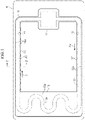
FIG. 1 is a schematic plan view showing a loop heat pipe of one embodiment. -
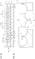
FIG. 2A is a schematic sectional view (a sectional view taken along a line 2-2 inFIG. 1 ) showing a liquid pipe of one embodiment. -
FIG. 2B is an enlarged sectional view of a part of the liquid pipe shown inFIG. 2A . -
FIG. 3 is a schematic perspective view showing a porous body of one embodiment. -
FIG. 4 is a schematic plan view showing the porous body of one embodiment. -
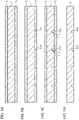
FIGS. 5A to 5D are schematic sectional views showing a manufacturing method of a loop heat pipe of one embodiment. -
FIGS. 6A to 6D are schematic sectional views showing the manufacturing method of the loop heat pipe of one embodiment. -
FIGS. 7A and 7B are schematic sectional views showing the manufacturing method of the loop heat pipe of one embodiment. -
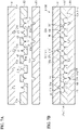
FIG. 8 is a schematic sectional view showing a loop heat pipe of a modified embodiment. -
FIG. 9 is a schematic sectional view showing a loop heat pipe of a modified embodiment. -
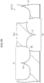
FIG. 10 is an enlarged sectional view of a part of the loop heat pipe of the modified embodiment. - Hereinafter, one embodiment will be described with reference to the accompanying drawings.
- Note that, for convenience sake, in the accompanying drawings, a characteristic part is enlarged so as to easily understand the feature, and the dimension ratios of the respective constitutional elements may be different in the respective drawings. Further, in the sectional views, hatching of some members is shown in a satin form, and hating of some members is omitted so as to easily understand a sectional structure of each member. Note that, in the present specification, 'in plan view' means seeing an object from a vertical direction (an upper and lower direction in the drawings) in
FIG. 2A and the like, and 'planar shape' means a shape of an object seen from the vertical direction inFIG. 2A and the like. Further, in the present specification, the 'upper and lower direction' and the 'right and left direction' are directions when a direction in which the reference numeral indicating each member can be correctly read in each drawing is set as the normal position. - A
loop heat pipe 10 shown inFIG. 1 is accommodated in a mobile electronic device M1 such as a smart phone and a tablet terminal. Theloop heat pipe 10 has anevaporator 11, avapor pipe 12, acondenser 13, and aliquid pipe 14. - The
evaporator 11 and thecondenser 13 are connected by thevapor pipe 12 and theliquid pipe 14. Theevaporator 11 has a function of vaporizing a working fluid C to generate steam Cv. The steam Cv generated in theevaporator 11 is sent to thecondenser 13 via thevapor pipe 12. Thecondenser 13 has a function of condensing the steam Cv of the working fluid C. The liquefied working fluid C is sent to theevaporator 11 via theliquid pipe 14. Thevapor pipe 12 and theliquid pipe 14 are configured to form a loop-like flow channel 15 through which the working fluid C or the steam Cv is caused to flow. - The
vapor pipe 12 is formed, for example, by an elongated pipe body. Theliquid pipe 14 is formed, for example, by an elongated pipe body. In the present embodiment, thevapor pipe 12 and theliquid pipe 14 are the same in dimension (i.e., length) in a length direction, for example. Note that, the length of thevapor pipe 12 and the length of theliquid pipe 14 may also be different from each other. For example, the length of thevapor pipe 12 may also be shorter than the length of theliquid pipe 14. Here, in the present specification, the 'length direction' of theevaporator 11, thevapor pipe 12, thecondenser 13 and theliquid pipe 14 is a direction that coincides with a direction (refer to an arrow in the drawing) in which the working fluid C or steam Cv flows in each member. - The
evaporator 11 is closely fixed to a heat-generating component (not shown). The working fluid C in theevaporator 11 is vaporized by heat generated by the heat-generating component, and steam Cv is accordingly generated. Note that, a thermal conduction member (TIM: Thermal Interface Material) may also be interposed between the evaporator 11 and the heat-generating component. The thermal conduction member is configured to reduce a contact thermal resistance between the heat-generating component and theevaporator 11 and to smooth heat conduction from the heat-generating component to theevaporator 11. - The
evaporator 12 has a pair ofpipe walls 12w provided on both sides in a width direction orthogonal to the length direction of theevaporator 12, in plan view, and aflow channel 12r provided between the pair ofpipe walls 12w, for example. Theflow channel 12r is formed to communicate with an internal space of theevaporator 11. Theflow channel 12r is a part of the loop-like flow channel 15. The steam Cv generated in theevaporator 11 is introduced into thecondenser 13 via thevapor pipe 12. - The
condenser 13 has aheat radiation plate 13p whose area is increased for heat radiation, and aserpentine flow channel 13r in theheat radiation plate 13p, for example. Theflow channel 13r is a part of the loop-like flow channel 15. The steam Cv introduced via thevapor pipe 12 is liquefied in the condenser33. - The
liquid pipe 14 has a pair ofpipe walls 14w provided on both sides in the width direction orthogonal to the length direction of theliquid pipe 14, in plan view, and aflow channel 14r provided between the pair ofpipe walls 14w, for example. Theflow channel 14r is formed to communicate with theflow channel 13r of thecondenser 13 and the internal space of theevaporator 11. Theflow channel 14r is a part of the loop-like flow channel 15. - The
liquid pipe 14 has aporous body 20. Theporous body 20 is formed to extend from thecondenser 13 to theevaporator 11 along the length direction of theliquid pipe 14, for example. Theporous body 20 is configured to guide the working fluid C liquefied in thecondenser 13 to theevaporator 11 by a capillary force generated in theporous body 20. That is, the working fluid C liquefied in thecondenser 13 is guided to theevaporator 11 through theliquid pipe 14. Note that, although not shown, a porous body similar to theporous body 20 is also provided in theevaporator 11. - In this way, in the
loop heat pipe 10, the heat generated by the heat-generating component is transferred to thecondenser 13 and radiated by thecondenser 13. Thereby, the heat-generating component is cooled, and the temperature rise of the heat-generating component is suppressed. - Here, as the working fluid C, a fluid having a high vapor pressure and a high latent heat of vaporization is preferably used. By using such working fluid C, it is possible to effectively cool the heat-generating component by the latent heat of vaporization. As the working fluid C, ammonia, water, freon, alcohol, acetone and the like can be used, for example.
-
FIG. 2A shows a section of theliquid pipe 14 taken along a line 2-2 ofFIG. 1 . The section is a face orthogonal to a direction (direction denoted with an arrow inFIG. 1 ) in which the working fluid C flows in theliquid pipe 14.FIG. 2B is an enlarged sectional view of a part of theliquid pipe 14 shown inFIG. 2A . - As shown in
FIG. 2A , theliquid pipe 14 has a structure where metal layers 31, 32 and 33 of three layers, for example, are laminated. In other words, theliquid pipe 14 has a structure where themetal layer 32, which is an inner metal layer, is laminated between the metal layers 31 and 33, which are a pair of outer metal layers. The inner metal layer of theliquid pipe 14 of the present embodiment is configured by only onemetal layer 32. - Each of the metal layers 31 to 33 is a copper (Cu) layer having excellent thermal conductivity. The plurality of
metal layers 31 to 33 is directly bonded to each other by solid-phase bonding such as diffusion joining, pressure welding, friction pressure welding and ultrasonic joining. Note that, inFIG. 2 , the metal layers 31 to 33 are identified by solid lines for easy understanding. For example, when the metal layers 31 to 33 are integrated by diffusion joining, interfaces of therespective metal layers 31 to 33 may be lost and boundaries may not be clear, in some cases. As used herein, the solid-phase bonding is a method of heating and softening joining targets in a solid-phase (solid) state without melting the same, and then further heating, plastically deforming and joining the joining targets. Note that, the metal layers 31 to 33 are not limited to the copper layers and may also be formed of stainless steel, aluminum, magnesium alloy or the like. In addition, for some of thelaminated metal layers 31 to 33, a material different from the other metal layers may also be used. A thickness of each of the metal layers 31 to 33 may be set to about 50 µm to 200 µm, for example. Note that, some of the metal layers 31 to 33 may be formed to have a thickness different from the other metal layers, and all the metal layers may be formed to have thicknesses different from each other. - The
liquid pipe 14 is configured by thelaminated metal layers 31 to 33, and has a pair ofpipe walls 14w provided at both ends in a width direction (a right and left direction inFIG. 2A ) of theliquid pipe 14 orthogonal to the laminating direction of the metal layers 31 to 33, and aporous body 20 provided between the pair ofpipe walls 14w. Theporous body 20 is formed to be continuous with, for example, thepipe walls 14w. - The
metal layer 31 is laminated on an upper face of themetal layer 32. A lower face of themetal layer 31 is formed with one ormore grooves 31g. Eachgroove 31g is formed to be recessed from the lower face of themetal layer 31 to a central portion in a thickness direction of themetal layer 31. - The
metal layer 32 is laminated between themetal layer 31 and themetal layer 33. The upper face (e.g. a first face) of themetal layer 32 is bonded to the lower face of themetal layer 31. A lower face (e.g. a second face) of themetal layer 32 is bonded to an upper face of themetal layer 33. Themetal layer 32 has a pair ofwall portions 32w provided at both ends in the width direction of theliquid pipe 14 and aporous body 32s provided between the pair ofwall portions 32w. - The
metal layer 33 is laminated on the lower face of themetal layer 32. The upper face of themetal layer 33 is formed with one ormore grooves 33g. Eachgroove 33g is formed to be recessed from the upper face of themetal layer 33 to a central portion in a thickness direction of themetal layer 33. - The
pipe wall 14w is configured by, for example, awall portion 32w of themetal layer 32 that is an inner metal layer. Eachpipe wall 14w of the present embodiment is configured by only thewall portion 32w. Eachwall portion 32w is not formed with a hole or a groove. - The
porous body 20 has, for example, theporous body 32s of themetal layer 32, which is the inner metal layer, and thegrooves - The
porous body 32s has a bottomedhole 40 recessed from the upper face of themetal layer 32 to the central portion in the thickness direction of themetal layer 32, and a bottomedhole 50 recessed from the lower face of themetal layer 32 to the central portion in the thickness direction of themetal layer 32. Theporous body 32s has apore 60 formed by partially communicating the bottomedhole 40 and the bottomedhole 50. The size, such as the diameter, of thepore 60 may be smaller than the size, such as taken in plan view, of each of the bottomedholes holes - As shown in
FIG. 2B , an inner face of each of the bottomedholes holes holes holes holes holes holes holes holes holes - Note that, the inner face of each of the bottomed
holes holes holes metal layer 32, and the inner side face of each of the bottomedholes - As shown in
FIGS. 3 and4 , the bottomedholes holes holes hole 40 and the bottomedhole 50 partially overlap in plan view. In the portion where the bottomedhole 40 and the bottomedhole 50 overlap in plan view, the bottomedhole 40 and the bottomedhole 50 partially communicate with each other to form thepore 60. Note that,FIG. 3 shows only the portion of themetal layer 32, which constitutes theporous body 32s (the bottomedholes - The bottomed
hole 40 has therein aconvex portion 41. That is, themetal layer 32 has aconvex portion 41 provided in the bottomedhole 40. Theconvex portion 41 is formed continuously and integrally with themetal layer 32 constituting the bottom face of the bottomedhole 40, for example. Theconvex portion 41 is provided, for example, apart from an entire circumference of the inner face of the bottomedhole 40. That is, a space is formed over the entire circumference of the bottomedhole 40 between an outer circumferential face of theconvex portion 41 and the inner face of the bottomedhole 40. In other words, theconvex portion 41 is provided at a central portion of the bottomedhole 40, in plan view. As shown inFIG. 4 , theconvex portion 41 of the present embodiment is provided at a center of the bottomedhole 40, in plan view. Theconvex portion 41 is provided, for example, at a position that does not overlap the entire bottomedhole 50, in plan view. - A planar shape of the
convex portion 41, e.g. in plan view onto the first face of themetal layer 32, can be formed to have arbitrary shape and size. The planar shape of theconvex portion 41 may be the same as the planar shape of the bottomedhole 40, or may be different from the planar shape of the bottomedhole 40. The size of the planar shape of theconvex portion 41 can be set to about 5% to 20% of a size of the planar shape of the bottomedhole 40, for example. For example, the planar shape of theconvex portion 41 can be formed in a circular shape having a diameter of about 5 µm to 50 µm. In the present embodiment, theconvex portion 41 is formed concentrically with the inner face of the bottomedhole 40. - As shown in
FIG. 2B , theconvex portion 41 has a proximal end and a distal end in a thickness direction of theconvex portion 41. The proximal end of theconvex portion 41 is connected to the bottom face of the bottomedhole 40. The distal end of theconvex portion 41 is provided on an opposite side to the proximal end in the thickness direction of theconvex portion 41. The distal end of theconvex portion 41 has, for example, a distal end face 41A formed into a flat face. Theconvex portion 41 extends from the bottom face of the bottomedhole 40 to the middle in the depth direction of the bottomedhole 40, in the thickness direction (upper and lower direction in the drawing) of themetal layer 32. That is, a thickness of theconvex portion 41 is set to a length shorter than the depth of the bottomedhole 40. Thedistal end face 41A of theconvex portion 41 is provided at a position further recessed toward the bottom face (here, downward) of the bottomedhole 40 than the upper face (one face or the first face) of themetal layer 32. In the thickness direction of theconvex portion 41, a distance between thedistal end face 41A of theconvex portion 41 and the bottom face of the bottomedhole 40 is smaller than a distance between the upper face of themetal layer 32 and the bottom face of the bottomedhole 40. The firstconvex portion 41 may have a height corresponding to at least 10% of the depth of the first bottomedhole 40. - The
convex portion 41 is formed, for example, in a tapered shape that tapers from the proximal end of theconvex portion 41 toward the distal end of theconvex portion 41. In other words, theconvex portion 41 is formed to be thicker from thedistal end face 41A of theconvex portion 41 toward the bottom face of the bottomedhole 40. An outer circumferential face of theconvex portion 41 is formed, for example, in a curved face curved in an arc shape, in a sectional view. - Note that, the
convex portion 41 may also be formed so that a central portion in the thickness direction of theconvex portion 41 is thinner than the proximal end and the distal end of theconvex portion 41. That is, theconvex portion 41 may also be formed so that the central portion in the thickness direction of theconvex portion 41 is thinnest. In this case, a sectional shape of the outer circumferential face of theconvex portion 41 is curved to have a 'constriction' at the central portion in the thickness direction of theconvex portion 41. In this case, the outer circumferential face of theconvex portion 41 is formed in a curved face curved in an arc shape, in a sectional view. In this case, theconvex portion 41 is formed to be thicker from the central portion in the thickness direction of theconvex portion 41 toward the distal end of theconvex portion 41. In this case, theconvex portion 41 is formed to be thicker from the central portion in the thickness direction of theconvex portion 41 toward the proximal end of theconvex portion 41. - The bottomed
hole 50 has therein aconvex portion 51. That is, themetal layer 32 has aconvex portion 51 provided in the bottomedhole 50. Theconvex portion 51 is formed continuously and integrally with themetal layer 32 constituting the bottom face of the bottomedhole 50, for example. Theconvex portion 51 is provided, for example, apart from an entire circumference of the inner face of the bottomedhole 50. That is, a space is formed over the entire circumference of the bottomedhole 50 between an outer circumferential face of theconvex portion 51 and the inner face of the bottomedhole 50. In other words, theconvex portion 51 is provided at a central portion of the bottomedhole 50, in plan view. As shown inFIG. 4 , theconvex portion 51 of the present embodiment is provided at a center of the bottomedhole 50, in plan view. Theconvex portion 51 is provided, for example, at a position that does not overlap the entire bottomedhole 40, in plan view. - A planar shape of the
convex portion 51 can be formed to have arbitrary shape and size. The planar shape of theconvex portion 51 may be the same as the planar shape of the bottomedhole 50, or may be different from the planar shape of the bottomedhole 50. The size of the planar shape of theconvex portion 51 can be set to about 5% to 20% of a size of the planar shape of the bottomedhole 50, for example. For example, the planar shape of theconvex portion 51 can be formed in a circular shape having a diameter of about 5 µm to 50 µm. In the present embodiment, theconvex portion 51 is formed concentrically with the inner face of the bottomedhole 50. - As shown in
FIG. 2B , theconvex portion 51 has a proximal end and a distal end in a thickness direction of theconvex portion 51. The proximal end of theconvex portion 51 is connected to the bottom face of the bottomedhole 50. The distal end of theconvex portion 51 is provided on an opposite side to the proximal end in the thickness direction of theconvex portion 51. The distal end of theconvex portion 51 has, for example, a distal end face 51A formed into a flat face. Theconvex portion 51 extends from the bottom face of the bottomedhole 50 to the middle in the depth direction of the bottomedhole 50, in the thickness direction (upper and lower direction in the drawing) of themetal layer 32. That is, a thickness of theconvex portion 51 is set to a length shorter than the depth of the bottomedhole 50. Thedistal end face 51A of theconvex portion 51 is provided at a position further recessed toward the bottom face (here, upward) of the bottomedhole 50 than the lower face (other face) of themetal layer 32. In the thickness direction of theconvex portion 51, a distance between thedistal end face 51A of theconvex portion 51 and the bottom face of the bottomedhole 50 is smaller than a distance between the lower face of themetal layer 32 and the bottom face of the bottomedhole 50. The secondconvex portion 51 may have a height corresponding to at least 10% of the depth of the second bottomedhole 50. - The
convex portion 51 is formed, for example, in a tapered shape that tapers from the proximal end of theconvex portion 51 toward the distal end of theconvex portion 51. In other words, theconvex portion 51 is formed to be thicker from thedistal end face 51A of theconvex portion 51 toward the bottom face of the bottomedhole 50. An outer circumferential face of theconvex portion 51 is formed, for example, in a curved face curved in an arc shape, in a sectional view. - Note that, the
convex portion 51 may also be formed so that a central portion in the thickness direction of theconvex portion 51 is thinner than the proximal end and the distal end of theconvex portion 51. That is, theconvex portion 51 may also be formed so that the central portion in the thickness direction of theconvex portion 51 is thinnest. In this case, a sectional shape of the outer circumferential face of theconvex portion 51 is curved to have a 'constriction' at the central portion in the thickness direction of theconvex portion 51. In this case, the outer circumferential face of theconvex portion 51 is formed in a curved face curved in an arc shape, in a sectional view. In this case, theconvex portion 51 is formed to be thicker from the central portion in the thickness direction of theconvex portion 51 toward the distal end of theconvex portion 51. In this case, theconvex portion 51 is formed to be thicker from the central portion in the thickness direction of theconvex portion 51 toward the proximal end of theconvex portion 51. - As shown in
FIG. 2A , thedistal end face 41A of theconvex portion 41 is provided apart from the lower face of themetal layer 31. A gap is formed between thedistal end face 41A of theconvex portion 41 and the lower face of themetal layer 31. Thedistal end face 51A of theconvex portion 51 is provided apart from the upper face of themetal layer 33. A gap is formed between thedistal end face 51A of theconvex portion 51 and the upper face of themetal layer 33. - A sectional shape of an inner face of each of the
grooves grooves grooves metal layer 31, for example. Note that, the inner face of each of thegrooves grooves grooves - As shown in
FIG. 4 , eachgroove 31g is provided at a position overlapping a portion of the bottomedhole 40, in plan view. Eachgroove 31g is formed to communicate with the bottomedhole 40. Eachgroove 31g is formed so that the plurality of adjacent bottomedholes 40 can communicate with each other. Eachgroove 31g is formed to extend along a direction in which the plurality of bottomedholes 40 is aligned, in plan view. The plurality ofgrooves 31g is formed to extend in parallel to each other, for example. Eachgroove 31g is provided, for example, at a position overlapping theconvex portion 41, in plan view. Eachgroove 31g is provided, for example, at a position overlapping a center of the bottomedhole 40, in plan view. - Each
groove 33g is provided at a position overlapping a portion of the bottomedhole 50, in plan view. Eachgroove 33g is formed to communicate with the bottomedhole 50. Eachgroove 33g is formed so that the plurality of adjacent bottomedholes 50 can communicate with each other. Eachgroove 33g is formed to extend along a direction in which the plurality of bottomedholes 50 is aligned, in plan view. The plurality ofgrooves 33g is formed to extend in parallel to each other, for example. Eachgroove 33g is formed to extend in a direction intersecting with thegroove 31g, in plan view, for example. Eachgroove 33g is provided, for example, at a position overlapping theconvex portion 51, in plan view. Eachgroove 33g is provided, for example, at a position overlapping a center of the bottomedhole 50, in plan view. - As shown in
FIG. 2A , the bottomedholes pores 60 formed in themetal layer 32 and thegrooves holes pores 60 and thegrooves pores 60, and thegrooves porous body 20 functions as aflow channel 14r through which the working fluid C (refer toFIG. 1 ) of the liquid phase flows. - Although not shown, the
liquid pipe 14 is provided with an injection port for injecting the working fluid C (refer toFIG. 1 ). However, the injection port is closed by a sealing member, so that an inside of theloop heat pipe 10 is kept airtight. - The
evaporator 11, thevapor pipe 12, and thecondenser 13 shown inFIG. 1 are formed by threelaminated metal layers 31 to 33 (refer toFIG. 2A ), like theliquid pipe 14 shown inFIG. 2A . That is, theloop heat pipe 10 shown inFIG. 1 is configured by laminating threemetal layers 31 to 33 (refer toFIG. 2A ). For example, in theevaporator 11, a porous body provided in theevaporator 11 is formed in a comb-teeth shape. In theevaporator 11, a region in which the porous body is not provided has a space. For example, in thevapor pipe 12, theflow channel 12r is formed by forming a through hole penetrating through the metal layer 32 (refer toFIG. 2A ), which is an inner metal layer, in the thickness direction. For example, in thecondenser 13, theflow channel 13r is formed by forming a through hole penetrating through the metal layer 32 (refer toFIG. 2A ), which is an inner metal layer, in the thickness direction. Note that, the number of the laminated metal layers is not limited to 3 layers, and may be 4 or more layers. - Next, operations of the
loop heat pipe 10 are described. - The
loop heat pipe 10 includes theevaporator 11 configured to vaporize the working fluid C, thevapor pipe 12 configured to cause the vaporized working fluid C (that is, steam Cv) to flow into thecondenser 13, thecondenser 13 configured to condense the steam Cv, and theliquid pipe 14 configured to cause the liquefied working fluid C to flow into theevaporator 11. - The
liquid pipe 14 is provided with theporous body 20. Theporous body 20 extends from thecondenser 13 to theevaporator 11 along the length direction of theliquid pipe 14. Theporous body 20 guides the working fluid C of the liquid phase liquefied in thecondenser 13 to theevaporator 11 by a capillary force generated in theporous body 20. - Here, as shown in
FIG. 2A , in theliquid pipe 14, theconvex portion 41 is provided in the bottomedhole 40 formed in themetal layer 32 that is the inner metal layer, and theconvex portion 51 is provided in the bottomedhole 50 formed in themetal layer 32. Thereby, volumes of the bottomedholes convex portions holes liquid pipe 14 undergoes a phase change from a liquid phase to a solid phase, an amount of the volume expansion can be reduced, as compared to the case where theconvex portions - In the present embodiment, the
metal layer 31 is an example of the first outer metal layer, themetal layer 32 is an example of the inner metal layer, and themetal layer 33 is an example of the second outer metal layer. In addition, the bottomedhole 40 is an example of the first bottomed hole, theconvex portion 41 is an example of the first convex portion, the bottomedhole 50 is an example of the second bottomed hole, theconvex portion 51 is an example of the second convex portion, thegroove 31g is an example of the first groove, and thegroove 33g is an example of the second groove. - Next, a manufacturing method of the
loop heat pipe 10 is described. - First, in a process shown in
FIG. 5A , a flat plate-like metal sheet 71 is prepared. Themetal sheet 71 is a member that finally becomes the metal layer 31 (refer toFIG. 2A ). Themetal sheet 71 is made of, for example, copper, stainless steel, aluminum, a magnesium alloy, or the like. A thickness of themetal sheet 71 may be set to about 50 µm to 200 µm, for example. - Subsequently, a resist
layer 72 is formed on an upper face of themetal sheet 71, and a resistlayer 73 is formed on a lower face of themetal sheet 71. As the resistlayers - Next, in a process shown in
FIG. 5B , the resistlayer 73 is exposed and developed to form openingportions 73X for selectively exposing the lower face of themetal sheet 71. The openingportions 73X are formed to correspond to thegrooves 31g shown inFIG. 2A . - Subsequently, in a process shown in
FIG. 5C , themetal sheet 71 exposed in the openingportions 73X is etched from the lower face-side of themetal sheet 71. Thereby, the lower face of themetal sheet 71 is formed withgrooves 31g. Thegrooves 31g can be formed by, for example, wet-etching themetal sheet 71 by using the resistlayers metal sheet 71, a ferric chloride aqueous solution or a copper chloride aqueous solution can be used as an etching solution. - Next, the resist
layers FIG. 5D , themetal layer 31 having thegrooves 31g in the lower face can be formed. - Next, in a process shown in
FIG. 6A , a flat plate-like metal sheet 74 is prepared. Themetal sheet 74 is a member that finally becomes the metal layer 32 (refer toFIG. 2A ). Themetal sheet 74 is made of, for example, copper, stainless steel, aluminum, a magnesium alloy, or the like. A thickness of themetal sheet 74 may be set to about 50 µm to 200 µm, for example. - Subsequently, a resist
layer 75 is formed on an upper face of themetal sheet 74, and a resistlayer 76 is formed on a lower face of themetal sheet 74. As the resistlayers - Next, in a process shown in
FIG. 6B , the resistlayer 75 is exposed and developed to form openingportions 75X for selectively exposing the upper face of themetal sheet 74. Similarly, the resistlayer 76 is exposed and developed to form openingportions 76X for selectively exposing the lower face of themetal sheet 74. The openingportions 75X are formed to correspond to the bottomedholes 40 shown inFIG. 2A . The openingportions 76X are formed to correspond to the bottomedholes 50 shown inFIG. 2A . The resistlayer 75 has a resistpattern 75A that covers the upper face of themetal sheet 74 at portions where theconvex portions 41 shown inFIG. 2B are formed. The resistpattern 75A is provided in the openingportions 75X. The resistlayer 76 has a resistpattern 76A that covers the lower face of themetal sheet 74 at portions where theconvex portions 51 shown inFIG. 2B are formed. The resistpattern 76A is provided in the openingportions 76X. - Next, in a process shown in
FIG. 6C , themetal sheet 74 exposed from the resistlayer 75 is etched from the upper face-side of themetal sheet 74, and themetal sheet 74 exposed from the resistlayer 76 is etched from the lower face-side of themetal sheet 74. By the resistpattern 75A and the openingportions 75X, bottomedholes 40 each having aconvex portion 41 are formed in the upper face of themetal sheet 74. At this time, a distal end (here, an upper end) of theconvex portion 41 is thinned, so that theconvex portion 41 is formed at a position where adistal end face 41A of theconvex portion 41 is further recessed downward than the upper face of themetal sheet 74. In addition, by the resistpattern 76A and the openingportions 76X, bottomedholes 50 each having aconvex portion 51 are formed in the lower face of themetal sheet 74. At this time, a distal end (here, a lower end) of theconvex portion 51 is thinned, so that theconvex portion 51 is formed at a position where adistal end face 51A of theconvex portion 51 is further recessed upward than the lower face of themetal sheet 74. The bottomedhole 40 and the bottomedhole 50 are formed to partially overlap each other, in plan view, and the bottomedhole 40 and the bottomedhole 50 communicate with each other at the overlapping portion to form apore 60. The bottomed holes 40 and 50 and theconvex portions metal sheet 74 by using the resistlayers metal sheet 74, a ferric chloride aqueous solution or a copper chloride aqueous solution can be used as an etching solution. - Next, the resist
layers FIG. 6D , themetal layer 32 having a pair ofwall portions 32w and aporous body 32s can be formed. - Subsequently, in a process shown in
FIG. 7A , themetal layer 33 is formed by a method similar to the processes shown inFIGS. 5A to 5D . Next, themetal layer 32 is arranged between themetal layer 31 and themetal layer 33. - Next, in a process shown in
FIG. 7B , thelaminated metal layers 31 to 33 are pressed while heating the same to a predetermined temperature (for example, about 900°C), so that the metal layers 31 to 33 are joined by the solid-phase bonding. Thereby, the metal layers 31, 32 and 33 adjacent to each other in the laminating direction are directly joined. - By the processes described above, a structure where the metal layers 31, 32, and 33 are laminated is formed. Then, the
loop heat pipe 10 having theevaporator 11, thevapor pipe 12, thecondenser 13, and theliquid pipe 14 shown inFIG. 1 is formed. At this time, theliquid pipe 14 is formed with theporous body 20. - Thereafter, for example, after exhausting the inside of the
liquid pipe 14 by using a vacuum pump or the like, the working fluid C is injected into theliquid pipe 14 from an injection port (not shown), and then the injection port is sealed. - Next, the operational effects of the present embodiment are described.
- (1) The
convex portion 41 is provided in the bottomedhole 40 formed in themetal layer 32 that is the inner metal layer. Thereby, the volume of the bottomedhole 40 can be reduced, as compared to a case where theconvex portion 41 is not provided, so that an amount of the working fluid C stored in the bottomedhole 50 can be reduced. Therefore, for example, when a volume expansion occurs as the working fluid C flowing in theliquid pipe 14 undergoes a phase change from a liquid phase to a solid phase, an amount of the volume expansion can be reduced, as compared to the case where theconvex portion 41 is not provided. For this reason, it is possible to suppress themetal layer 31, which is the outer metal layer, from being deformed to bulge outward due to the volume expansion of the working fluid C. Therefore, it is possible to suppress themetal layer 31 from peeling from themetal layer 32. For example, even in a case where an electronic device M1 having theloop heat pipe 10 is used in an environment such as a cold region where an ambient temperature is lower than a freezing point of the working fluid C and the working fluid C of the liquid phase freezes and undergoes freezing and expansion, it is possible to suppress themetal layer 31 from peeling from themetal layer 32. - (2) The
convex portion 51 is provided in the bottomedhole 50 formed in themetal layer 32 that is the inner metal layer. Thereby, the volume of the bottomedhole 50 can be reduced, as compared to a case where theconvex portion 51 is not provided, so that an amount of the working fluid C stored in the bottomedhole 50 can be reduced. Therefore, for example, when a volume expansion occurs as the working fluid C flowing in theliquid pipe 14 undergoes a phase change from a liquid phase to a solid phase, an amount of the volume expansion can be reduced, as compared to the case where theconvex portion 51 is not provided. For this reason, it is possible to suppress themetal layer 33, which is the outer metal layer, from being deformed to bulge outward due to the volume expansion of the working fluid C. Therefore, it is possible to suppress themetal layer 33 from peeling from themetal layer 32. - (3) The
grooves holes metal layer 32 of a single layer. By forming thegrooves holes pores 60 and thegrooves metal layer 32 of a single layer, and theliquid pipe 14 can be configured by the threemetal layers 31 to 33. Thereby, theliquid pipe 14 can be made thin. Further, theloop heat pipe 10 can be made thin. - (4) The
convex portion 41 is provided at the center of the plane of the bottomedhole 40, and thegroove 31g is formed to overlap theconvex portion 41, in plan view. For this reason, thegroove 31g is formed to overlap the center of the bottomedhole 40, in plan view. Thereby, even when the position of thegroove 31g slightly deviates from a target position due to a manufacturing error or the like, for example, thegroove 31g can be favorably formed to communicate with the bottomedhole 40. - (5) The distal end of the
convex portion 41 is provided with the distal end face 41A formed into a flat face. According to this configuration, the volume of theconvex portion 41 can be increased, as compared to a case where the distal end of theconvex portion 41 is formed in a needle shape, so that the volume of the bottomedhole 40 can be reduced. Thereby, the amount of the working fluid C stored in the bottomedhole 40 can be reduced, and the amount of volume expansion of the working fluid C can be reduced. - The above embodiment can be changed and implemented, as follows. The above embodiment and the following modified examples can be implemented in combination with each other within a technically consistent range.
- As shown in
FIG. 8 , theliquid pipe 14 may be provided with theporous body 20 and a flow channel 21 (first flow channel). Theliquid pipe 14 of the present modified example has a pair ofpipe walls 14w, a pair ofporous bodies 20 formed to be continuous with the pair ofpipe walls 14w, and a flow channel provided between the pair ofporous bodies 20. In theliquid pipe 14 of the present modified example, theflow channel 14r of theliquid pipe 14 is configured by the flow channel of theporous body 20 and theflow channel 21. Note that, theporous body 20 is configured by theporous body 32s of themetal layer 32 and thegrooves - A sectional area of the
flow channel 21 is formed to be larger than a sectional area of the flow channel of theporous body 20, for example. Theflow channel 21 is configured by a through-hole 32X penetrating through themetal layer 32, which is the inner metal layer, in the thickness direction. For example, theflow channel 21 is configured to communicate with the flow channel of theporous body 20. For example, the through-hole 32X is configured to communicate with at least one of the bottomedholes metal layer 32. - Also in this case, the
convex portions holes - As shown in
FIG. 9 , theliquid pipe 14 may be provided with theporous body 20 and a plurality of flow channels 22 (first flow channel). Theliquid pipe 14 of the present modified example has a pair ofpipe walls 14w, aporous body 20 provided apart from eachpipe wall 14w, and twoflow channels 22 provided between eachpipe wall 14w and theporous body 20. In theliquid pipe 14 of the present modified example, theflow channel 14r of theliquid pipe 14 is configured by the flow channel of theporous body 20 and the twoflow channels 22. Theporous body 20 of the present modified example is provided at a central portion in the width direction of theliquid pipe 14. Theporous body 20 is provided apart from thepipe wall 14w by theflow channel 22. Note that, theporous body 20 is configured by theporous body 32s of themetal layer 32 and thegrooves - A sectional area of each
flow channel 22 is formed larger than a sectional area of the flow channel of theporous body 20, for example. Eachflow channel 22 is configured by a through-hole 32Y penetrating through themetal layer 32, which is the inner metal layer, in the thickness direction. For example, eachflow channel 22 is configured to communicate with the flow channel of theporous body 20. For example, each through-hole 32Y is configured to communicate with at least one of the bottomedholes metal layer 32. - Also in this case, the
convex portions holes - In the above embodiment, the
porous body 20 including the bottomedholes convex portions liquid pipe 14. However, the present invention is not limited thereto. For example, theporous body 20 may also be provided in theevaporator 11, thesteam tube 12 or thecondenser 13. For example, theporous body 20 may be provided in at least one of theevaporator 11, thevapor pipe 12, thecondenser 13, and theliquid pipe 14. For example, theporous body 20 may also be provided only in thevapor pipe 12. - The shapes of the bottomed
holes convex portions porous body 20 of the above embodiment may also be appropriately changed. - For example, as shown in
FIG. 10 , the distal end of theconvex portion 41 may also be formed into a needle-like pointed shape. Similarly, the distal end of theconvex portion 51 may also be formed into a needle-like pointed shape. - Further, in the
porous body 32s, aconvex portion 41 having a needle-shaped distal end and aconvex portion 41 having a distal end face 41A formed into a flat face may coexist. Similarly, in theporous body 32s, aconvex portion 51 having a needle-shaped distal end and aconvex portion 51 having a distal end face 51A formed into a flat face may coexist. - In the
porous body 20 of the above embodiment, the depth of the bottomedhole 40 provided in the upper face of themetal layer 32 and the depth of the bottomedhole 50 provided in the lower face of themetal layer 32 may be different. - In the above embodiment, the
convex portions holes convex portion 41 may also be provided only in the bottomedhole 40 of the bottomedholes convex portion 51 may also be omitted. For example, theconvex portion 51 may also be provided only in the bottomedhole 50 of the bottomedholes convex portion 41 may also be omitted. - In the above embodiment, the
convex portions 41 are provided in all the bottomed holes 50. However, the present invention is not limited thereto. For example, theconvex portion 41 may be provided in at least one bottomedhole 40 of the plurality of bottomed holes 40. - In the above embodiment, the
convex portions 51 are provided in all the bottomed holes 50. However, the present invention is not limited thereto. For example, theconvex portion 51 may be provided in at least one bottomedhole 50 of the plurality of bottomed holes 50. - In the above embodiment, a plurality of
convex portions 41 may also be provided in one bottomedhole 40. - In the above embodiment, a plurality of
convex portions 51 may also be provided in one bottomedhole 50. - In the above embodiment, the inner metal layer is configured by only the
metal layer 32 of a single layer. That is, the inner metal layer is formed to have a single layer structure. However, the present invention is not limited thereto. For example, the inner metal layer may also be formed to have a laminated structure where a plurality of metal layers is laminated. In this case, the inner metal layer is configured by a plurality of metal layers laminated between themetal layer 31 and themetal layer 33. Further, each of the plurality of metal layers constituting the inner metal layer has a porous body similar to theporous body 32s. Further, if the inner metal layer is configured by a plurality of metal layers, the lower face of themetal layer 31 may not be formed with one ormore grooves 31g, and the upper face of themetal layer 33 may not be formed with one ormore grooves 33g.
Claims (13)
- A loop heat pipe (10) comprising:an evaporator (11) configured to vaporize a working fluid (C);a condenser (13) configured to condense the working fluid (C);a liquid pipe (14) that connects the evaporator (11) and the condenser (13) to each other;a vapor pipe (12) that connects the evaporator (11) and the condenser (13) to each other, anda loop-like flow channel (21, 22) that is provided in each of the evaporator (11), the condenser (13), the liquid pipe (14), and the vapor pipe (12), and through which the working fluid can flow,
whereinat least one of the evaporator (11), the condenser (13), the liquid pipe (14) and the vapor pipe (14) comprises a first outer metal layer (31), a second outer metal layer (33), and an inner metal layer (33) that is provided between the first outer metal layer (31) and the second outer metal layer (33), andthe inner metal layer (32) comprises a porous body (20), whereinthe porous body (20) comprisesa first bottomed hole (40) formed in one face of the inner metal layer (32),a second bottomed hole (50) formed in the other face of the inner metal layer (32),a pore (60), wherein the first bottomed hole (40) and the second bottomed hole (50) partially communicates with each other through the pore (60), anda first convex portion (41) provided inside the first bottomed hole (40), whereinthe first convex portion (41) has a proximal end connected to a bottom face of the first bottomed hole (40) and a distal end provided on an opposite side to the proximal end in a thickness direction of the first convex portion (41), andthe distal end of the first convex portion (41) is provided at a position further recessed toward the bottom face of the first bottomed hole (40) than the one face of the inner metal layer (32). - The loop heat pipe according to Claim 1, whereinthe first outer metal layer (31) is bonded to the one face of the inner metal layer (32), andthe first outer metal layer (31) comprises a first groove (31g) communicating with the first bottomed hole (40).
- The loop heat pipe according to Claim 2, wherein
the first groove (31g) overlaps with the first convex portion (41) in plan view. - The loop heat pipe according to any one of Claims 1 to 3, whereinthe porous body (20) further comprises a second convex portion (51) provided inside the second bottomed hole (50),the second convex portion (51) comprises a proximal end connected to a bottom face of the second bottomed hole (50) and a distal end provided on an opposite side to the proximal end in a thickness direction of the second convex portion (51), andwherein the distal end of the second convex portion (51) is provided at a position further recessed toward the bottom face of the second bottomed hole (50) than the other face of the inner metal layer (32).
- The loop heat pipe according to Claim 4, wherein:the inner metal layer (32) is a single inner metal layer;the second outer metal layer (33) is bonded to the other face of the inner metal layer (32); andthe second outer metal layer (33) comprises a second groove (33g) communicating with the second bottomed hole (50).
- The loop heat pipe according to Claim 5, wherein:
the second groove (33g) overlaps with the second convex portion (51), in plan view. - The loop heat pipe according to any one of Claims 4 to 6, wherein:
the distal end of the second convex portion (51) is provided spaced apart from the second outer metal layer (33). - The loop heat pipe according to any one of Claims 4 to 7, wherein:
the second convex portion (51) has a height corresponding to at least 10% of a depth of the second bottomed hole (50). - The loop heat pipe according to any one of Claims 1 to 8, wherein:
a distal end of the first convex portion (41) has a distal end face (41A) formed into a flat face. - The loop heat pipe according to any one of Claims 1 to 9, wherein:
the first convex portion (41) is provided at a center of the first bottomed hole (40) in plan view. - The loop heat pipe according to any one of Claims 1 to 10, wherein:the liquid pipe (14) comprises the first outer metal layer (31), the second outer metal layer (33), and the inner metal layer (32);the inner metal layer (32) of the liquid pipe (14) comprises the porous body (20) and a first flow channel (21) that is larger in a sectional area than a flow channel configured by the porous body (20); andthe first bottomed hole (40) and the second bottomed hole (50) communicate with the first flow channel (21).
- The loop heat pipe according to any one of Claims 1 to 11, wherein:
the distal end of the first convex portion (41) is provided spaced apart from the first outer metal layer (31). - The loop heat pipe according to any one of Claims 1 to 12, wherein:
the first convex portion (41) has a height corresponding to at least 10% of a depth of the first bottomed hole (40).
Applications Claiming Priority (1)
| Application Number | Priority Date | Filing Date | Title |
|---|---|---|---|
| JP2021074035A JP7525438B2 (en) | 2021-04-26 | 2021-04-26 | Loop Heat Pipe |
Publications (2)
| Publication Number | Publication Date |
|---|---|
| EP4083562A1 true EP4083562A1 (en) | 2022-11-02 |
| EP4083562B1 EP4083562B1 (en) | 2023-09-13 |
Family
ID=81346555
Family Applications (1)
| Application Number | Title | Priority Date | Filing Date |
|---|---|---|---|
| EP22169484.7A Active EP4083562B1 (en) | 2021-04-26 | 2022-04-22 | Loop heat pipe |
Country Status (4)
| Country | Link |
|---|---|
| US (1) | US11892241B2 (en) |
| EP (1) | EP4083562B1 (en) |
| JP (1) | JP7525438B2 (en) |
| CN (1) | CN115247973A (en) |
Citations (5)
| Publication number | Priority date | Publication date | Assignee | Title |
|---|---|---|---|---|
| JP6291000B2 (en) | 2016-09-01 | 2018-03-07 | 新光電気工業株式会社 | Loop heat pipe and manufacturing method thereof |
| US20180164043A1 (en) * | 2016-12-14 | 2018-06-14 | Shinko Electric Industries Co., Ltd. | Heat pipe |
| JP6400240B1 (en) | 2018-02-05 | 2018-10-03 | 新光電気工業株式会社 | Loop heat pipe and manufacturing method thereof |
| US20200200485A1 (en) * | 2018-12-19 | 2020-06-25 | Shinko Electric Industries Co., Ltd. | Loop-type heat pipe |
| US20200378686A1 (en) * | 2019-05-31 | 2020-12-03 | Shinko Electric Industries Co., Ltd. | Loop-type heat pipe |
Family Cites Families (8)
| Publication number | Priority date | Publication date | Assignee | Title |
|---|---|---|---|---|
| JPS6291000U (en) | 1985-11-26 | 1987-06-10 | ||
| JPS64240U (en) | 1987-06-19 | 1989-01-05 | ||
| JP2010133581A (en) * | 2008-12-02 | 2010-06-17 | Kobelco & Materials Copper Tube Inc | Inner helically grooved tube for heat pipe and the heat pipe |
| JP2018009717A (en) * | 2016-07-12 | 2018-01-18 | 株式会社フジクラ | Oscillation type heat pipe |
| JP6799503B2 (en) * | 2016-12-14 | 2020-12-16 | 新光電気工業株式会社 | Heat pipe and its manufacturing method |
| JP7015197B2 (en) * | 2018-03-26 | 2022-02-02 | 新光電気工業株式会社 | Loop type heat pipe and its manufacturing method |
| JP7205745B2 (en) * | 2018-04-17 | 2023-01-17 | 大日本印刷株式会社 | Vapor chamber, electronic device, metal sheet for vapor chamber and method for manufacturing vapor chamber |
| JP6801698B2 (en) * | 2018-09-04 | 2020-12-16 | セイコーエプソン株式会社 | Cooling device and projector |
-
2021
- 2021-04-26 JP JP2021074035A patent/JP7525438B2/en active Active
-
2022
- 2022-04-22 EP EP22169484.7A patent/EP4083562B1/en active Active
- 2022-04-22 US US17/727,045 patent/US11892241B2/en active Active
- 2022-04-26 CN CN202210444347.XA patent/CN115247973A/en active Pending
Patent Citations (6)
| Publication number | Priority date | Publication date | Assignee | Title |
|---|---|---|---|---|
| JP6291000B2 (en) | 2016-09-01 | 2018-03-07 | 新光電気工業株式会社 | Loop heat pipe and manufacturing method thereof |
| US20180164043A1 (en) * | 2016-12-14 | 2018-06-14 | Shinko Electric Industries Co., Ltd. | Heat pipe |
| JP6400240B1 (en) | 2018-02-05 | 2018-10-03 | 新光電気工業株式会社 | Loop heat pipe and manufacturing method thereof |
| EP3524911A1 (en) * | 2018-02-05 | 2019-08-14 | Shinko Electric Industries Co., Ltd. | Loop heat pipe and method of manufacturing loop heat pipe |
| US20200200485A1 (en) * | 2018-12-19 | 2020-06-25 | Shinko Electric Industries Co., Ltd. | Loop-type heat pipe |
| US20200378686A1 (en) * | 2019-05-31 | 2020-12-03 | Shinko Electric Industries Co., Ltd. | Loop-type heat pipe |
Also Published As
| Publication number | Publication date |
|---|---|
| US20220341679A1 (en) | 2022-10-27 |
| JP7525438B2 (en) | 2024-07-30 |
| EP4083562B1 (en) | 2023-09-13 |
| US11892241B2 (en) | 2024-02-06 |
| JP2022168514A (en) | 2022-11-08 |
| CN115247973A (en) | 2022-10-28 |
Similar Documents
| Publication | Publication Date | Title |
|---|---|---|
| US10876799B2 (en) | Loop heat pipe | |
| CN112683092A (en) | Loop type heat pipe and manufacturing method thereof | |
| US11592240B2 (en) | Loop-type heat pipe with vapor moving path in liquid pipe | |
| JP2019132486A (en) | Loop type heat pipe, manufacturing method of loop type heat pipe | |
| US11802740B2 (en) | Loop heat pipe with reinforcing member | |
| EP4083562B1 (en) | Loop heat pipe | |
| US11719490B2 (en) | Loop heat pipe with recessed outer wall surface | |
| EP4043822A1 (en) | Loop heat pipe | |
| US12498180B2 (en) | Heat pipe | |
| US12571598B2 (en) | Loop-type heat pipe | |
| US12392561B2 (en) | Loop-type heat pipe | |
| US12050063B2 (en) | Loop heat pipe |
Legal Events
| Date | Code | Title | Description |
|---|---|---|---|
| PUAI | Public reference made under article 153(3) epc to a published international application that has entered the european phase |
Free format text: ORIGINAL CODE: 0009012 |
|
| STAA | Information on the status of an ep patent application or granted ep patent |
Free format text: STATUS: THE APPLICATION HAS BEEN PUBLISHED |
|
| STAA | Information on the status of an ep patent application or granted ep patent |
Free format text: STATUS: REQUEST FOR EXAMINATION WAS MADE |
|
| AK | Designated contracting states |
Kind code of ref document: A1 Designated state(s): AL AT BE BG CH CY CZ DE DK EE ES FI FR GB GR HR HU IE IS IT LI LT LU LV MC MK MT NL NO PL PT RO RS SE SI SK SM TR |
|
| 17P | Request for examination filed |
Effective date: 20221025 |
|
| RBV | Designated contracting states (corrected) |
Designated state(s): AL AT BE BG CH CY CZ DE DK EE ES FI FR GB GR HR HU IE IS IT LI LT LU LV MC MK MT NL NO PL PT RO RS SE SI SK SM TR |
|
| GRAP | Despatch of communication of intention to grant a patent |
Free format text: ORIGINAL CODE: EPIDOSNIGR1 |
|
| STAA | Information on the status of an ep patent application or granted ep patent |
Free format text: STATUS: GRANT OF PATENT IS INTENDED |
|
| RIC1 | Information provided on ipc code assigned before grant |
Ipc: F28D 15/02 19850101AFI20230102BHEP |
|
| INTG | Intention to grant announced |
Effective date: 20230201 |
|
| RIN1 | Information on inventor provided before grant (corrected) |
Inventor name: MACHIDA, YOSHIHIRO |
|
| GRAJ | Information related to disapproval of communication of intention to grant by the applicant or resumption of examination proceedings by the epo deleted |
Free format text: ORIGINAL CODE: EPIDOSDIGR1 |
|
| STAA | Information on the status of an ep patent application or granted ep patent |
Free format text: STATUS: REQUEST FOR EXAMINATION WAS MADE |
|
| GRAP | Despatch of communication of intention to grant a patent |
Free format text: ORIGINAL CODE: EPIDOSNIGR1 |
|
| STAA | Information on the status of an ep patent application or granted ep patent |
Free format text: STATUS: GRANT OF PATENT IS INTENDED |
|
| INTC | Intention to grant announced (deleted) | ||
| INTG | Intention to grant announced |
Effective date: 20230411 |
|
| GRAS | Grant fee paid |
Free format text: ORIGINAL CODE: EPIDOSNIGR3 |
|
| GRAA | (expected) grant |
Free format text: ORIGINAL CODE: 0009210 |
|
| STAA | Information on the status of an ep patent application or granted ep patent |
Free format text: STATUS: THE PATENT HAS BEEN GRANTED |
|
| AK | Designated contracting states |
Kind code of ref document: B1 Designated state(s): AL AT BE BG CH CY CZ DE DK EE ES FI FR GB GR HR HU IE IS IT LI LT LU LV MC MK MT NL NO PL PT RO RS SE SI SK SM TR |
|
| REG | Reference to a national code |
Ref country code: CH Ref legal event code: EP |
|
| REG | Reference to a national code |
Ref country code: DE Ref legal event code: R096 Ref document number: 602022000494 Country of ref document: DE |
|
| REG | Reference to a national code |
Ref country code: IE Ref legal event code: FG4D |
|
| REG | Reference to a national code |
Ref country code: LT Ref legal event code: MG9D |
|
| REG | Reference to a national code |
Ref country code: NL Ref legal event code: MP Effective date: 20230913 |
|
| PG25 | Lapsed in a contracting state [announced via postgrant information from national office to epo] |
Ref country code: GR Free format text: LAPSE BECAUSE OF FAILURE TO SUBMIT A TRANSLATION OF THE DESCRIPTION OR TO PAY THE FEE WITHIN THE PRESCRIBED TIME-LIMIT Effective date: 20231214 |
|
| PG25 | Lapsed in a contracting state [announced via postgrant information from national office to epo] |
Ref country code: SE Free format text: LAPSE BECAUSE OF FAILURE TO SUBMIT A TRANSLATION OF THE DESCRIPTION OR TO PAY THE FEE WITHIN THE PRESCRIBED TIME-LIMIT Effective date: 20230913 Ref country code: RS Free format text: LAPSE BECAUSE OF FAILURE TO SUBMIT A TRANSLATION OF THE DESCRIPTION OR TO PAY THE FEE WITHIN THE PRESCRIBED TIME-LIMIT Effective date: 20230913 Ref country code: NO Free format text: LAPSE BECAUSE OF FAILURE TO SUBMIT A TRANSLATION OF THE DESCRIPTION OR TO PAY THE FEE WITHIN THE PRESCRIBED TIME-LIMIT Effective date: 20231213 Ref country code: LV Free format text: LAPSE BECAUSE OF FAILURE TO SUBMIT A TRANSLATION OF THE DESCRIPTION OR TO PAY THE FEE WITHIN THE PRESCRIBED TIME-LIMIT Effective date: 20230913 Ref country code: LT Free format text: LAPSE BECAUSE OF FAILURE TO SUBMIT A TRANSLATION OF THE DESCRIPTION OR TO PAY THE FEE WITHIN THE PRESCRIBED TIME-LIMIT Effective date: 20230913 Ref country code: HR Free format text: LAPSE BECAUSE OF FAILURE TO SUBMIT A TRANSLATION OF THE DESCRIPTION OR TO PAY THE FEE WITHIN THE PRESCRIBED TIME-LIMIT Effective date: 20230913 Ref country code: GR Free format text: LAPSE BECAUSE OF FAILURE TO SUBMIT A TRANSLATION OF THE DESCRIPTION OR TO PAY THE FEE WITHIN THE PRESCRIBED TIME-LIMIT Effective date: 20231214 Ref country code: FI Free format text: LAPSE BECAUSE OF FAILURE TO SUBMIT A TRANSLATION OF THE DESCRIPTION OR TO PAY THE FEE WITHIN THE PRESCRIBED TIME-LIMIT Effective date: 20230913 |
|
| REG | Reference to a national code |
Ref country code: AT Ref legal event code: MK05 Ref document number: 1611680 Country of ref document: AT Kind code of ref document: T Effective date: 20230913 |
|
| PG25 | Lapsed in a contracting state [announced via postgrant information from national office to epo] |
Ref country code: NL Free format text: LAPSE BECAUSE OF FAILURE TO SUBMIT A TRANSLATION OF THE DESCRIPTION OR TO PAY THE FEE WITHIN THE PRESCRIBED TIME-LIMIT Effective date: 20230913 |
|
| PG25 | Lapsed in a contracting state [announced via postgrant information from national office to epo] |
Ref country code: IS Free format text: LAPSE BECAUSE OF FAILURE TO SUBMIT A TRANSLATION OF THE DESCRIPTION OR TO PAY THE FEE WITHIN THE PRESCRIBED TIME-LIMIT Effective date: 20240113 |
|
| PG25 | Lapsed in a contracting state [announced via postgrant information from national office to epo] |
Ref country code: AT Free format text: LAPSE BECAUSE OF FAILURE TO SUBMIT A TRANSLATION OF THE DESCRIPTION OR TO PAY THE FEE WITHIN THE PRESCRIBED TIME-LIMIT Effective date: 20230913 |
|
| PG25 | Lapsed in a contracting state [announced via postgrant information from national office to epo] |
Ref country code: ES Free format text: LAPSE BECAUSE OF FAILURE TO SUBMIT A TRANSLATION OF THE DESCRIPTION OR TO PAY THE FEE WITHIN THE PRESCRIBED TIME-LIMIT Effective date: 20230913 |
|
| PG25 | Lapsed in a contracting state [announced via postgrant information from national office to epo] |
Ref country code: SM Free format text: LAPSE BECAUSE OF FAILURE TO SUBMIT A TRANSLATION OF THE DESCRIPTION OR TO PAY THE FEE WITHIN THE PRESCRIBED TIME-LIMIT Effective date: 20230913 Ref country code: RO Free format text: LAPSE BECAUSE OF FAILURE TO SUBMIT A TRANSLATION OF THE DESCRIPTION OR TO PAY THE FEE WITHIN THE PRESCRIBED TIME-LIMIT Effective date: 20230913 Ref country code: IS Free format text: LAPSE BECAUSE OF FAILURE TO SUBMIT A TRANSLATION OF THE DESCRIPTION OR TO PAY THE FEE WITHIN THE PRESCRIBED TIME-LIMIT Effective date: 20240113 Ref country code: ES Free format text: LAPSE BECAUSE OF FAILURE TO SUBMIT A TRANSLATION OF THE DESCRIPTION OR TO PAY THE FEE WITHIN THE PRESCRIBED TIME-LIMIT Effective date: 20230913 Ref country code: EE Free format text: LAPSE BECAUSE OF FAILURE TO SUBMIT A TRANSLATION OF THE DESCRIPTION OR TO PAY THE FEE WITHIN THE PRESCRIBED TIME-LIMIT Effective date: 20230913 Ref country code: CZ Free format text: LAPSE BECAUSE OF FAILURE TO SUBMIT A TRANSLATION OF THE DESCRIPTION OR TO PAY THE FEE WITHIN THE PRESCRIBED TIME-LIMIT Effective date: 20230913 Ref country code: AT Free format text: LAPSE BECAUSE OF FAILURE TO SUBMIT A TRANSLATION OF THE DESCRIPTION OR TO PAY THE FEE WITHIN THE PRESCRIBED TIME-LIMIT Effective date: 20230913 Ref country code: PT Free format text: LAPSE BECAUSE OF FAILURE TO SUBMIT A TRANSLATION OF THE DESCRIPTION OR TO PAY THE FEE WITHIN THE PRESCRIBED TIME-LIMIT Effective date: 20240115 Ref country code: SK Free format text: LAPSE BECAUSE OF FAILURE TO SUBMIT A TRANSLATION OF THE DESCRIPTION OR TO PAY THE FEE WITHIN THE PRESCRIBED TIME-LIMIT Effective date: 20230913 |
|
| PG25 | Lapsed in a contracting state [announced via postgrant information from national office to epo] |
Ref country code: PL Free format text: LAPSE BECAUSE OF FAILURE TO SUBMIT A TRANSLATION OF THE DESCRIPTION OR TO PAY THE FEE WITHIN THE PRESCRIBED TIME-LIMIT Effective date: 20230913 Ref country code: IT Free format text: LAPSE BECAUSE OF FAILURE TO SUBMIT A TRANSLATION OF THE DESCRIPTION OR TO PAY THE FEE WITHIN THE PRESCRIBED TIME-LIMIT Effective date: 20230913 |
|
| REG | Reference to a national code |
Ref country code: DE Ref legal event code: R097 Ref document number: 602022000494 Country of ref document: DE |
|
| PG25 | Lapsed in a contracting state [announced via postgrant information from national office to epo] |
Ref country code: DK Free format text: LAPSE BECAUSE OF FAILURE TO SUBMIT A TRANSLATION OF THE DESCRIPTION OR TO PAY THE FEE WITHIN THE PRESCRIBED TIME-LIMIT Effective date: 20230913 |
|
| PLBE | No opposition filed within time limit |
Free format text: ORIGINAL CODE: 0009261 |
|
| STAA | Information on the status of an ep patent application or granted ep patent |
Free format text: STATUS: NO OPPOSITION FILED WITHIN TIME LIMIT |
|
| PG25 | Lapsed in a contracting state [announced via postgrant information from national office to epo] |
Ref country code: DK Free format text: LAPSE BECAUSE OF FAILURE TO SUBMIT A TRANSLATION OF THE DESCRIPTION OR TO PAY THE FEE WITHIN THE PRESCRIBED TIME-LIMIT Effective date: 20230913 |
|
| 26N | No opposition filed |
Effective date: 20240614 |
|
| PG25 | Lapsed in a contracting state [announced via postgrant information from national office to epo] |
Ref country code: SI Free format text: LAPSE BECAUSE OF FAILURE TO SUBMIT A TRANSLATION OF THE DESCRIPTION OR TO PAY THE FEE WITHIN THE PRESCRIBED TIME-LIMIT Effective date: 20230913 |
|
| PG25 | Lapsed in a contracting state [announced via postgrant information from national office to epo] |
Ref country code: SI Free format text: LAPSE BECAUSE OF FAILURE TO SUBMIT A TRANSLATION OF THE DESCRIPTION OR TO PAY THE FEE WITHIN THE PRESCRIBED TIME-LIMIT Effective date: 20230913 |
|
| PG25 | Lapsed in a contracting state [announced via postgrant information from national office to epo] |
Ref country code: BG Free format text: LAPSE BECAUSE OF FAILURE TO SUBMIT A TRANSLATION OF THE DESCRIPTION OR TO PAY THE FEE WITHIN THE PRESCRIBED TIME-LIMIT Effective date: 20230913 |
|
| PG25 | Lapsed in a contracting state [announced via postgrant information from national office to epo] |
Ref country code: MC Free format text: LAPSE BECAUSE OF FAILURE TO SUBMIT A TRANSLATION OF THE DESCRIPTION OR TO PAY THE FEE WITHIN THE PRESCRIBED TIME-LIMIT Effective date: 20230913 |
|
| PG25 | Lapsed in a contracting state [announced via postgrant information from national office to epo] |
Ref country code: MC Free format text: LAPSE BECAUSE OF FAILURE TO SUBMIT A TRANSLATION OF THE DESCRIPTION OR TO PAY THE FEE WITHIN THE PRESCRIBED TIME-LIMIT Effective date: 20230913 Ref country code: BG Free format text: LAPSE BECAUSE OF FAILURE TO SUBMIT A TRANSLATION OF THE DESCRIPTION OR TO PAY THE FEE WITHIN THE PRESCRIBED TIME-LIMIT Effective date: 20230913 |
|
| PG25 | Lapsed in a contracting state [announced via postgrant information from national office to epo] |
Ref country code: LU Free format text: LAPSE BECAUSE OF NON-PAYMENT OF DUE FEES Effective date: 20240422 |
|
| REG | Reference to a national code |
Ref country code: BE Ref legal event code: MM Effective date: 20240430 |
|
| PG25 | Lapsed in a contracting state [announced via postgrant information from national office to epo] |
Ref country code: LU Free format text: LAPSE BECAUSE OF NON-PAYMENT OF DUE FEES Effective date: 20240422 |
|
| PG25 | Lapsed in a contracting state [announced via postgrant information from national office to epo] |
Ref country code: BE Free format text: LAPSE BECAUSE OF NON-PAYMENT OF DUE FEES Effective date: 20240430 |
|
| PG25 | Lapsed in a contracting state [announced via postgrant information from national office to epo] |
Ref country code: FR Free format text: LAPSE BECAUSE OF NON-PAYMENT OF DUE FEES Effective date: 20240430 |
|
| PG25 | Lapsed in a contracting state [announced via postgrant information from national office to epo] |
Ref country code: FR Free format text: LAPSE BECAUSE OF NON-PAYMENT OF DUE FEES Effective date: 20240430 Ref country code: BE Free format text: LAPSE BECAUSE OF NON-PAYMENT OF DUE FEES Effective date: 20240430 |
|
| PG25 | Lapsed in a contracting state [announced via postgrant information from national office to epo] |
Ref country code: IE Free format text: LAPSE BECAUSE OF NON-PAYMENT OF DUE FEES Effective date: 20240422 |
|
| PGFP | Annual fee paid to national office [announced via postgrant information from national office to epo] |
Ref country code: DE Payment date: 20250305 Year of fee payment: 4 |
|
| PG25 | Lapsed in a contracting state [announced via postgrant information from national office to epo] |
Ref country code: CY Free format text: LAPSE BECAUSE OF FAILURE TO SUBMIT A TRANSLATION OF THE DESCRIPTION OR TO PAY THE FEE WITHIN THE PRESCRIBED TIME-LIMIT; INVALID AB INITIO Effective date: 20220422 |
|
| PG25 | Lapsed in a contracting state [announced via postgrant information from national office to epo] |
Ref country code: HU Free format text: LAPSE BECAUSE OF FAILURE TO SUBMIT A TRANSLATION OF THE DESCRIPTION OR TO PAY THE FEE WITHIN THE PRESCRIBED TIME-LIMIT; INVALID AB INITIO Effective date: 20220422 |
|
| REG | Reference to a national code |
Ref country code: CH Ref legal event code: H13 Free format text: ST27 STATUS EVENT CODE: U-0-0-H10-H13 (AS PROVIDED BY THE NATIONAL OFFICE) Effective date: 20251125 |
|
| PG25 | Lapsed in a contracting state [announced via postgrant information from national office to epo] |
Ref country code: CH Free format text: LAPSE BECAUSE OF NON-PAYMENT OF DUE FEES Effective date: 20250430 |