EP4083509A1 - Method for calibrating a gas turbine burner during recondition or production by using a calibrating pin - Google Patents
Method for calibrating a gas turbine burner during recondition or production by using a calibrating pin Download PDFInfo
- Publication number
- EP4083509A1 EP4083509A1 EP21171664.2A EP21171664A EP4083509A1 EP 4083509 A1 EP4083509 A1 EP 4083509A1 EP 21171664 A EP21171664 A EP 21171664A EP 4083509 A1 EP4083509 A1 EP 4083509A1
- Authority
- EP
- European Patent Office
- Prior art keywords
- hole
- gas
- outlet
- calibrating
- gas turbine
- Prior art date
- Legal status (The legal status is an assumption and is not a legal conclusion. Google has not performed a legal analysis and makes no representation as to the accuracy of the status listed.)
- Granted
Links
Images


Classifications
-
- F—MECHANICAL ENGINEERING; LIGHTING; HEATING; WEAPONS; BLASTING
- F23—COMBUSTION APPARATUS; COMBUSTION PROCESSES
- F23R—GENERATING COMBUSTION PRODUCTS OF HIGH PRESSURE OR HIGH VELOCITY, e.g. GAS-TURBINE COMBUSTION CHAMBERS
- F23R3/00—Continuous combustion chambers using liquid or gaseous fuel
- F23R3/28—Continuous combustion chambers using liquid or gaseous fuel characterised by the fuel supply
- F23R3/286—Continuous combustion chambers using liquid or gaseous fuel characterised by the fuel supply having fuel-air premixing devices
-
- B—PERFORMING OPERATIONS; TRANSPORTING
- B23—MACHINE TOOLS; METAL-WORKING NOT OTHERWISE PROVIDED FOR
- B23P—METAL-WORKING NOT OTHERWISE PROVIDED FOR; COMBINED OPERATIONS; UNIVERSAL MACHINE TOOLS
- B23P6/00—Restoring or reconditioning objects
- B23P6/002—Repairing turbine components, e.g. moving or stationary blades, rotors
-
- F—MECHANICAL ENGINEERING; LIGHTING; HEATING; WEAPONS; BLASTING
- F23—COMBUSTION APPARATUS; COMBUSTION PROCESSES
- F23R—GENERATING COMBUSTION PRODUCTS OF HIGH PRESSURE OR HIGH VELOCITY, e.g. GAS-TURBINE COMBUSTION CHAMBERS
- F23R3/00—Continuous combustion chambers using liquid or gaseous fuel
- F23R3/02—Continuous combustion chambers using liquid or gaseous fuel characterised by the air-flow or gas-flow configuration
- F23R3/04—Air inlet arrangements
- F23R3/10—Air inlet arrangements for primary air
- F23R3/12—Air inlet arrangements for primary air inducing a vortex
- F23R3/14—Air inlet arrangements for primary air inducing a vortex by using swirl vanes
-
- F—MECHANICAL ENGINEERING; LIGHTING; HEATING; WEAPONS; BLASTING
- F23—COMBUSTION APPARATUS; COMBUSTION PROCESSES
- F23R—GENERATING COMBUSTION PRODUCTS OF HIGH PRESSURE OR HIGH VELOCITY, e.g. GAS-TURBINE COMBUSTION CHAMBERS
- F23R3/00—Continuous combustion chambers using liquid or gaseous fuel
- F23R3/42—Continuous combustion chambers using liquid or gaseous fuel characterised by the arrangement or form of the flame tubes or combustion chambers
- F23R3/58—Cyclone or vortex type combustion chambers
-
- B—PERFORMING OPERATIONS; TRANSPORTING
- B23—MACHINE TOOLS; METAL-WORKING NOT OTHERWISE PROVIDED FOR
- B23P—METAL-WORKING NOT OTHERWISE PROVIDED FOR; COMBINED OPERATIONS; UNIVERSAL MACHINE TOOLS
- B23P2700/00—Indexing scheme relating to the articles being treated, e.g. manufactured, repaired, assembled, connected or other operations covered in the subgroups
- B23P2700/13—Parts of turbine combustion chambers
Definitions
- the present invention relates to the technical field of gas turbine assemblies for power plants.
- gas turbine assemblies for power plants.
- an incoming air flow is compressed in a compressor and then mixed with fuel (gas fuel and/or oil fuel) in a combustor to produce a hot gas flow to be expanded in a turbine.
- the combustor comprises a plurality of burners wherein each burner is provided with a plurality of holes configured for injecting fuel in the air flow.
- the rotation of the turbine generates a rotating work on a rotor in turn connected to a generator for power production.
- the present invention in detail, refers to how to improve the combustion performance.
- a gas turbine for power plants comprises a compressor assembly, a combustor assembly and a turbine assembly.
- the compressor assembly is configured for compressing incoming air supplied at a compressor inlet.
- the compressed air leaving the compressor assembly flows into a volume (called "plenum") and from there into the combustor assembly.
- This combustor assembly comprises usually a plurality of burners configured for injecting fuel (at least one type of fuel) into the compressed air flow.
- Each burner comprises a plurality of holes configured for injecting gas fuel into the airflow.
- the mixture of fuel and compressed air enters a combustion chamber where this mixture ignites.
- the resulting hot gas flow leaves the combustion chamber and by passing in the turbine assembly performs a rotating work on the rotor connected to a generator.
- the turbine assembly comprises a plurality of stages, or rows, of rotating blades that are interposed by a plurality of stages, or rows, of stator blades, called vanes.
- the rotating blades are supported by the rotor whereas the stator blades are supported by a casing (called “vane carrier”) that is concentric and surrounding the turbine assembly.
- a sequential gas turbine comprises a first and a second combustion stage wherein each combustion stage is provided with a plurality of burners.
- the first and the second combustor are annular shaped and are physically separated by a stage of turbine blades, called high pressure turbine. Downstream the second combustor a second turbine unit is present (called low pressure turbine).
- This kind of gas turbine is produced by the Applicant and is available on the market as "GT26".
- the gas turbine is not provided with the high-pressure turbine and the combustor assembly is realized in form of a plurality of can-combustors arranged as a ring around the gas turbine axis.
- Each can-combustor comprises a first combustor and a second combustor arranged directly one downstream the other inside a common can shaped casing.
- This second kind of a sequential gas turbine is produced by the Applicant and is available on the market as "GT36".
- the present invention can be applied in all foregoing described gas turbines and, in general, in all gas turbine provided with burners having gas fuel injecting holes.
- each of the above mentioned injecting holes comprises an inlet connected to a fuel gas source and an outlet at right angles to air flowing through the burner slots.
- the holes injecting fuel gas can only be produced by EDM (Electro Discharge Machining), which is an inherently imprecise process.
- EDM Electro Discharge Machining
- the individual burner scatter of the total fuel gas flow is ⁇ 10%, which causes a flame temperature variation of more than 100°C between individual burners.
- the fuel gas flow scatter between individual holes is ⁇ 15%, which causes local flame temperature variations.
- a solution to limit the gas scatter of the fuel gas leaving the burner injecting holes provides that the burners should be selectively assembled to reduce the downstream measured hot gas path circumferential temperature distribution.
- a calibration orifice could also be installed in each burner to reduce the fuel flow scatter.
- this solution is not used because it would increase the pressure drop over the burners necessitating a larger gas compressor. Moreover, this solution would not improve the distribution of fuel gas along the burner air slots.
- a primary object of the present invention is to provide a method for calibrating a gas turbine burner, wherein this method can be easily performed during recondition or production of the gas turbine assembly.
- an assembly comprising:
- each combustor comprises a plurality of burners, i.e. devices configured for injecting fuel, in this case gas fuel, into the airflow coming from the compressor.
- fuel in this case gas fuel
- the controlled reduction of the outlet diameter by using a specific device allows to overcome the problem foregoing cited of the prior art, namely, to easily ensure an improved gas flow distribution and a minimal gas flow scatter between individual injection holes.
- the resulting hole diameters are checked using a standard measuring pin to ensure that the hole diameter variation decreases, i.e. that the fuel distribution in the burner air slots improves.
- the reduction of the deformed the hole outlet is performed by using a calibrating pin device, i.e. a device preferably comprising a pin having a diameter slightly larger than the initial EDM outlet diameter of each hole and an enlarged base.
- a calibrating pin device i.e. a device preferably comprising a pin having a diameter slightly larger than the initial EDM outlet diameter of each hole and an enlarged base.
- the base is provided with a circular projecting ring around the pin so that by pressing the pin into each hole a circular indentation is obtained at the hole outlet thus uniformly reducing the outlet diameter.
- the calibrating pin is a hardened pin, i.e. a pin made of a harder material than the burner.
- the invention also provides a final step of checking if after the deformation the reduced outlet diameter is larger than the required minimum diameter. For allowing this check a minimum diameter measuring pin is inserted in each hole.
- the present invention also refers to any gas turbine burner, wherein the gas injecting holes are calibrated by performing a method according to any one of the foregoing claims.
- the present invention also refers to any gas turbine assembly comprising at least a burner as foregoing calibrated.
- a gas turbine assembly for power plants.
- a gas turbine assembly comprises a compressor, a combustor assembly and at least a turbine.
- the compressor and the turbine extend along a main axis and preferably are linked to a common rotor.
- FIG. 1 is a schematic view of a first non-limiting example of a gas turbine assembly for power plant 1 wherein the method of the present invention can be applied.
- this gas turbine is a so called "sequential-combustion gas turbine" provided with a high-pressure and a low-pressure turbine.
- the gas turbine 1 of figure 1 comprises a compressor 3, a first combustor 31, a high-pressure turbine 5, a second combustor 32 and a low-pressure turbine 7.
- the compressor 3 and the two turbines 5, 7 are part of or are connected to a common rotor 8 rotating about an axis 9 and surrounded by a concentric casing 10.
- the compressor 3 is supplied with air and comprises rotating blades 18 and stator vanes 19 configured to compress the air entering the compressor 3. Exiting the compressor, the compressed air flows into a plenum 11 and from there into a plurality of first burners 12 of the first combustor 31 arranged in a circular pattern around the axis 9.
- Each first burner 12 is configured for injecting at least one type of fuel (for instance gas fuel connected to at least one first fuel supply 13) into the compressed air flow.
- this first burner 12 may be defined as a "premix" burner because is configured for mixing the compressed air and the injected fuel before the ignition.
- the fuel/compressed air mixture flows into a first combustion chamber 4 annularly shaped, where this mixture ignites.
- this mixture is initially ignited by an ignitor, for instance by a spark igniter; once ignited the ignition is self-sustaining and the ignitor is turned off.
- the resulting hot gas leaves the first combustor chamber 4 and is partially expanded in the high-pressure turbine 5 performing work on the rotor 8.
- Downstream of the high-pressure turbine 5 the partially-expanded hot gas flows into a row of second burners 33 where at least one type of fuel is injected by fuel lances 14 (each burner has one lance).
- the partially expanded gas has a high temperature and contains sufficient oxygen for further combustion that occurs by self-ignition in the second combustion chamber 6 arranged downstream of the row second burners 33.
- These second burners 33 are also called "reheat" burners.
- the reheated hot gas leaves the second combustion chamber 6 and flows in the low-pressure turbine 7 where it is expanded performing work on the rotor 8.
- the low-pressure turbine 7 comprises numerous stages: rows of rotor blades 15 arranged in series in the main flow direction. Such rows of blades 15 are interposed by rows of stator vanes 16.
- the rotor blades 15 are connected to the rotor 8 whereas the stator vanes 16 are connected to a vane carrier 17 that is a concentric casing surrounding the low-pressure turbine 7.
- FIG. 2 is a schematic view of a second not-limiting example of a gas turbine wherein the method of the present invention can be applied.
- this gas turbine 20 is a "sequential-combustion gas turbine".
- figure 2 discloses a partial view of a gas turbine 20 with a compressor 29, a turbine 21 and a sequential combustor 22.
- the sequential combustor 22 of figure 2 has a plurality of so-called can combustors, i.e. numerous bolt-on can-casings wherein each can comprises a plurality of first burners 24, a first combustion chamber 25, a second burners 26, and a second combustion chamber 27.
- each of the first burners 24 of this embodiment is a "premix" burner configured for generating a premixed flame.
- FIG. 1 and 2 are non-limiting example of gas turbines that can be calibrated according to the present invention.
- FIG 3 is a schematic embodiment of a turbine burner that can be calibrated according to the invention.
- This burner 12 may be a burner assembled in the gas turbines of figures 1 and 2 .
- the upstream end 32 is connected to a gas fuel source 13 and the downstream end 33 is conical shaped provided with a plurality of injecting holes 31 configured for injecting gas fuel coming from the source 13 to the airflow.
- these holes have to be calibrated for improving the burner performance. Indeed, this the fuel gas holes in this burner are produced by EDM and therefore these holes are not accurately calibrated.
- Figures 4-6 disclose an embodiment of a calibrating device suitable for performing the claimed method, i.e. suitable for calibrating the holes 31 of the burner 12.
- calibrating we mean the step of deforming the hole outlets by using a device configured so that the outlet of each hole is deformed from the original outlet diameter (produced by EDM technology) to a reduced outlet diameter.
- figures 4-6 disclose a calibrating pin 34 device comprising a pin 35 (cylindrical main body) having a diameter slightly larger than the initial EDM outlet diameter of each hole 31. Please notice that these holes 31 before the calibration are not cylindrical, they have a slight taper so that the pin 35 can enter the hole 31 until an enlarged base 36 of the device is pressed into contact with the outer surface of the burner around the hole 31.
- the face of the base 36 configured to contact to the burner surface around the hole 31 is provided with a circular projecting ring 37 arranged around the pin 37.
- the circular projecting ring 37 discloses a circular V-shaped sharp edge that in use is pressed against the surface of the burner around the hole 31.
- the diameter of the pin is 2,2mm (reference D) whereas the V-shaped edge is has a diameter equal to 2,5mm (reference D').
- the height of this projection 37 is configured to deform the edge of the EDM hole 31 outlet as disclosed in the following figures.
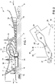
- Figures 7 and 8 disclose a burner hole for injecting fuel gas in the airflow respectively before and after the calibration performed by the device of figures 4-6 .
- the reference 38 refers to the surface of the burner around the hole 31, i.e. the burner surface in contact with the pin base 36.
- the reference 39 refers to the hole outlet before the calibration and the reference 40 refers to the hole outlet before the calibration.
- the reference 39 refers to the gas fuel flow.
- the outlet end 40 discloses a diameter less that the original outlet due to a deformation of the outlet itself. Indeed by pressing the pin 35 into the hole 31 the base 36 contacts the surface 38 and, by pressing again as represented by F', the protruding V-shaped ring creates a circular indentation 41 around the outlet. As a consequence of this indentation, the edge of the hole outlet is deformed to reduce the exit diameter for the gas flow.
- References d and d' in figure 8 refer respectively to the outlet diameter before and after the calibration.
Landscapes
- Engineering & Computer Science (AREA)
- Mechanical Engineering (AREA)
- Chemical & Material Sciences (AREA)
- Combustion & Propulsion (AREA)
- General Engineering & Computer Science (AREA)
- Pre-Mixing And Non-Premixing Gas Burner (AREA)
- Gas Burners (AREA)
Abstract
Description
- The present invention relates to the technical field of gas turbine assemblies for power plants. As known, in these assemblies an incoming air flow is compressed in a compressor and then mixed with fuel (gas fuel and/or oil fuel) in a combustor to produce a hot gas flow to be expanded in a turbine. The combustor comprises a plurality of burners wherein each burner is provided with a plurality of holes configured for injecting fuel in the air flow. The rotation of the turbine generates a rotating work on a rotor in turn connected to a generator for power production. In this technical field, the present invention, in detail, refers to how to improve the combustion performance.
- As known, a gas turbine for power plants comprises a compressor assembly, a combustor assembly and a turbine assembly. The compressor assembly is configured for compressing incoming air supplied at a compressor inlet. The compressed air leaving the compressor assembly flows into a volume (called "plenum") and from there into the combustor assembly. This combustor assembly comprises usually a plurality of burners configured for injecting fuel (at least one type of fuel) into the compressed air flow. Each burner comprises a plurality of holes configured for injecting gas fuel into the airflow. The mixture of fuel and compressed air enters a combustion chamber where this mixture ignites. The resulting hot gas flow leaves the combustion chamber and by passing in the turbine assembly performs a rotating work on the rotor connected to a generator. As known, the turbine assembly comprises a plurality of stages, or rows, of rotating blades that are interposed by a plurality of stages, or rows, of stator blades, called vanes. The rotating blades are supported by the rotor whereas the stator blades are supported by a casing (called "vane carrier") that is concentric and surrounding the turbine assembly.
- In order to achieve a high efficiency, the hot gas flow has to have a very high turbine inlet temperature. However, in general this high temperature involves an undesired high NOx emission level. In order to reduce this emission and to increase operational flexibility without decreasing the efficiency, a so called "sequential" gas turbine is particularly suitable. In general, a sequential gas turbine comprises a first and a second combustion stage wherein each combustion stage is provided with a plurality of burners. Today at least two different kinds of sequential gas turbines are known. According to a first embodiment, the first and the second combustor are annular shaped and are physically separated by a stage of turbine blades, called high pressure turbine. Downstream the second combustor a second turbine unit is present (called low pressure turbine). This kind of gas turbine is produced by the Applicant and is available on the market as "GT26". According to a second embodiment of a sequential gas turbine, the gas turbine is not provided with the high-pressure turbine and the combustor assembly is realized in form of a plurality of can-combustors arranged as a ring around the gas turbine axis. Each can-combustor comprises a first combustor and a second combustor arranged directly one downstream the other inside a common can shaped casing. This second kind of a sequential gas turbine is produced by the Applicant and is available on the market as "GT36". The present invention can be applied in all foregoing described gas turbines and, in general, in all gas turbine provided with burners having gas fuel injecting holes.
- According to the invention, each of the above mentioned injecting holes comprises an inlet connected to a fuel gas source and an outlet at right angles to air flowing through the burner slots. As known, to achieve an optimal burner performance in a gas turbine it is necessary to reduce the fuel gas flow scatter, for instance to a fuel gas flow scatter of ± 2% for the GT26 produced by the applicant. Because of limited access inside the burner slots, the holes injecting fuel gas can only be produced by EDM (Electro Discharge Machining), which is an inherently imprecise process. In this condition, the individual burner scatter of the total fuel gas flow is ± 10%, which causes a flame temperature variation of more than 100°C between individual burners. Additionally, the fuel gas flow scatter between individual holes is ± 15%, which causes local flame temperature variations.
- According to the prior art practice, a solution to limit the gas scatter of the fuel gas leaving the burner injecting holes provides that the burners should be selectively assembled to reduce the downstream measured hot gas path circumferential temperature distribution. A calibration orifice could also be installed in each burner to reduce the fuel flow scatter. However, this solution is not used because it would increase the pressure drop over the burners necessitating a larger gas compressor. Moreover, this solution would not improve the distribution of fuel gas along the burner air slots.
- Starting from this prior art practice, today there is the need to provide a new and inventive solution to limit the fuel gas scatter of the gas leaving the fuel injecting holes in a gas turbine burner.
- Accordingly, a primary object of the present invention is to provide a method for calibrating a gas turbine burner, wherein this method can be easily performed during recondition or production of the gas turbine assembly.
- As gas turbine assembly we mean, as foregoing described, an assembly comprising:
- a compressor;
- at least a combustor;
- at least a turbine.
- Even not listed, other minor components of these assemblies are well known by the skill person of this technical field. As known, each combustor comprises a plurality of burners, i.e. devices configured for injecting fuel, in this case gas fuel, into the airflow coming from the compressor. Starting from this point, according the main definition of the invention the method comprises the steps of:
- a) providing a gas turbine burner (usually a gas turbine comprising a plurality of burners) comprising a plurality of holes configured for injecting gas fuel in an airflow (i.e. compressed air leaving the compressor); each gas fuel injecting hole comprises an outlet having an initial or first the outlet diameter, preferably as produced by EDM (the hole outlet is at right angles to the airflow);
- b) deforming the hole outlets by using a tool or device configured so that the outlet of each hole is deformed by passing from the initial EDM outlet diameter to a smaller outlet diameter.
- The controlled reduction of the outlet diameter by using a specific device allows to overcome the problem foregoing cited of the prior art, namely, to easily ensure an improved gas flow distribution and a minimal gas flow scatter between individual injection holes. The resulting hole diameters are checked using a standard measuring pin to ensure that the hole diameter variation decreases, i.e. that the fuel distribution in the burner air slots improves.
- According to a preferred embodiment of the invention the reduction of the deformed the hole outlet is performed by using a calibrating pin device, i.e. a device preferably comprising a pin having a diameter slightly larger than the initial EDM outlet diameter of each hole and an enlarged base. In this example the base is provided with a circular projecting ring around the pin so that by pressing the pin into each hole a circular indentation is obtained at the hole outlet thus uniformly reducing the outlet diameter.
- Preferably, the calibrating pin is a hardened pin, i.e. a pin made of a harder material than the burner.
- The invention also provides a final step of checking if after the deformation the reduced outlet diameter is larger than the required minimum diameter. For allowing this check a minimum diameter measuring pin is inserted in each hole.
- Of course, the present invention also refers to any gas turbine burner, wherein the gas injecting holes are calibrated by performing a method according to any one of the foregoing claims. Finally, the present invention also refers to any gas turbine assembly comprising at least a burner as foregoing calibrated.
- It being understood that both the foregoing general description and the following detailed description are exemplary and are intended to provide further explanation of the invention as claimed. Other advantages and features of the invention will be apparent from the following description, drawings and claims.
- The features of the invention believed to be novel are set forth with particularity in the appended claims.
- Further benefits and advantages of the present invention will be evident after a careful reading of the detailed description with appropriate reference to the annexed drawings.
- The invention itself, however, may be better understood by referring to the following detailed description of the invention, which describes an exemplary embodiment of the invention, taken in conjunction with the annexed drawings, in which:
-
figures 1 and 2 are schematic views of two gas turbine assemblies wherein the method of the present invention can be applied. -
figure 3 is a schematic embodiment of a turbine burner that can be calibrated according to the invention; -
figures 4-6 disclose an embodiment of a calibrating device suitable for performing the claimed method; -
figures 7 and 8 disclose a burner hole for injecting fuel gas in the airflow respectively before and after the calibration performed by the device offigures 4-6 . - In cooperation with the attached drawings, the technical contents and detailed description of the present invention are described thereinafter according to the preferred embodiments, being not used to limit its executing scope. Any equivalent technical variation and modification made according to appended claims is all covered by the claims claimed by the present invention.
- As foregoing cites, the technical field of the present application refers to the gas turbine assembly for power plants. The skilled person well knows that a gas turbine assembly comprises a compressor, a combustor assembly and at least a turbine. The compressor and the turbine extend along a main axis and preferably are linked to a common rotor.
- Reference is now made to
Fig. 1 that is a schematic view of a first non-limiting example of a gas turbine assembly for power plant 1 wherein the method of the present invention can be applied. According to the embodiment offigure 1 this gas turbine is a so called "sequential-combustion gas turbine" provided with a high-pressure and a low-pressure turbine. Following themain gas flow 2, the gas turbine 1 offigure 1 comprises acompressor 3, afirst combustor 31, a high-pressure turbine 5, asecond combustor 32 and a low-pressure turbine 7. Thecompressor 3 and the twoturbines 5, 7 are part of or are connected to acommon rotor 8 rotating about anaxis 9 and surrounded by aconcentric casing 10. Thecompressor 3 is supplied with air and comprisesrotating blades 18 andstator vanes 19 configured to compress the air entering thecompressor 3. Exiting the compressor, the compressed air flows into aplenum 11 and from there into a plurality offirst burners 12 of thefirst combustor 31 arranged in a circular pattern around theaxis 9. Eachfirst burner 12 is configured for injecting at least one type of fuel (for instance gas fuel connected to at least one first fuel supply 13) into the compressed air flow. Preferably, thisfirst burner 12 may be defined as a "premix" burner because is configured for mixing the compressed air and the injected fuel before the ignition. The fuel/compressed air mixture flows into a first combustion chamber 4 annularly shaped, where this mixture ignites. During start-up this mixture is initially ignited by an ignitor, for instance by a spark igniter; once ignited the ignition is self-sustaining and the ignitor is turned off. The resulting hot gas leaves the first combustor chamber 4 and is partially expanded in the high-pressure turbine 5 performing work on therotor 8. Downstream of the high-pressure turbine 5 the partially-expanded hot gas flows into a row ofsecond burners 33 where at least one type of fuel is injected by fuel lances 14 (each burner has one lance). The partially expanded gas has a high temperature and contains sufficient oxygen for further combustion that occurs by self-ignition in thesecond combustion chamber 6 arranged downstream of the rowsecond burners 33. Thesesecond burners 33 are also called "reheat" burners. The reheated hot gas leaves thesecond combustion chamber 6 and flows in the low-pressure turbine 7 where it is expanded performing work on therotor 8. The low-pressure turbine 7 comprises numerous stages: rows ofrotor blades 15 arranged in series in the main flow direction. Such rows ofblades 15 are interposed by rows ofstator vanes 16. Therotor blades 15 are connected to therotor 8 whereas thestator vanes 16 are connected to avane carrier 17 that is a concentric casing surrounding the low-pressure turbine 7. - Reference is now made to
Fig. 2 that is a schematic view of a second not-limiting example of a gas turbine wherein the method of the present invention can be applied. Also, thisgas turbine 20 is a "sequential-combustion gas turbine". In particular,figure 2 discloses a partial view of agas turbine 20 with acompressor 29, aturbine 21 and asequential combustor 22. Thesequential combustor 22 offigure 2 has a plurality of so-called can combustors, i.e. numerous bolt-on can-casings wherein each can comprises a plurality offirst burners 24, afirst combustion chamber 25, asecond burners 26, and asecond combustion chamber 27. Upstream of thesecond burner 26 an mixer may be provided for adding air into the hot gas leaving thefirst combustion chamber 25 and creating turbulence in the air/hot gas mixture. The sequential combustor arrangement is at least in part housed in anouter casing 28 supporting the individual can combustors 22 arranged in a circular pattern around the turbine axis 23. Also, each of thefirst burners 24 of this embodiment is a "premix" burner configured for generating a premixed flame. When the hot gas leaves thesecond combustion chamber 27 it then expands in theturbine 21 performing work on arotor 30. - As foregoing cited, the examples of
figures 1 and 2 are non-limiting example of gas turbines that can be calibrated according to the present invention. -
Figure 3 is a schematic embodiment of a turbine burner that can be calibrated according to the invention. Thisburner 12 may be a burner assembled in the gas turbines offigures 1 and 2 . In this example, theupstream end 32 is connected to agas fuel source 13 and thedownstream end 33 is conical shaped provided with a plurality of injectingholes 31 configured for injecting gas fuel coming from thesource 13 to the airflow. As foregoing described, these holes have to be calibrated for improving the burner performance. Indeed, this the fuel gas holes in this burner are produced by EDM and therefore these holes are not accurately calibrated. -
Figures 4-6 disclose an embodiment of a calibrating device suitable for performing the claimed method, i.e. suitable for calibrating theholes 31 of theburner 12. With the word "calibrating" we mean the step of deforming the hole outlets by using a device configured so that the outlet of each hole is deformed from the original outlet diameter (produced by EDM technology) to a reduced outlet diameter. In particular,figures 4-6 disclose a calibratingpin 34 device comprising a pin 35 (cylindrical main body) having a diameter slightly larger than the initial EDM outlet diameter of eachhole 31. Please notice that theseholes 31 before the calibration are not cylindrical, they have a slight taper so that thepin 35 can enter thehole 31 until anenlarged base 36 of the device is pressed into contact with the outer surface of the burner around thehole 31. The face of the base 36 configured to contact to the burner surface around thehole 31 is provided with a circular projectingring 37 arranged around thepin 37. In this example, the circular projectingring 37 discloses a circular V-shaped sharp edge that in use is pressed against the surface of the burner around thehole 31. In this example the diameter of the pin is 2,2mm (reference D) whereas the V-shaped edge is has a diameter equal to 2,5mm (reference D'). The height of thisprojection 37 is configured to deform the edge of theEDM hole 31 outlet as disclosed in the following figures. -
Figures 7 and 8 disclose a burner hole for injecting fuel gas in the airflow respectively before and after the calibration performed by the device offigures 4-6 . Thereference 38 refers to the surface of the burner around thehole 31, i.e. the burner surface in contact with thepin base 36. Thereference 39 refers to the hole outlet before the calibration and thereference 40 refers to the hole outlet before the calibration. Thereference 39 refers to the gas fuel flow. As disclosed, after the calibration theoutlet end 40 discloses a diameter less that the original outlet due to a deformation of the outlet itself. Indeed by pressing thepin 35 into thehole 31 the base 36 contacts thesurface 38 and, by pressing again as represented by F', the protruding V-shaped ring creates acircular indentation 41 around the outlet. As a consequence of this indentation, the edge of the hole outlet is deformed to reduce the exit diameter for the gas flow. References d and d' infigure 8 refer respectively to the outlet diameter before and after the calibration. - Although the invention has been explained in relation to its preferred embodiment(s) as mentioned above, it is to be understood that many other possible modifications and variations can be made without departing from the scope of the present invention. It is, therefore, contemplated that the appended claim or claims will cover such modifications and variations that fall within the true scope of the invention.
Claims (9)
- A method for calibrating a gas turbine burner during recondition or production; the method comprising the steps of:a) providing a gas turbine burner comprising a plurality of holes configured for injecting gas fuel in an airflow, each hole comprising an outlet having an initial outlet diameter;b) deforming the hole outlets by using a calibrating device configured so that the outlet of each hole is deformed from the initial outlet diameter to a smaller outlet diameter.
- Method as claimed in claim 1, wherein the step b) is performed by using a calibrating pin device.
- Method as claimed in claim 2, wherein the calibrating pin device used in step b) comprises a pin having a diameter slightly larger than the initial outlet diameter of each hole and an enlarged base; the base being provided with a circular projecting ring around the pin.
- Method as claimed in claim 3, wherein the step b) is performed by pressing the pin into each hole so that at the outlet of each hole a ring indentation is obtained by the projecting V-shaped ring.
- Method as claimed in any one of the foregoing claims, wherein in step a) at least the gas injecting holes are manufactured by an EDM process.
- Method as claimed in any one of the foregoing claims, wherein the method comprises also the step of checking if after the deformation the reduced outlet diameter is larger than a minimum required diameter.
- Method as claimed in claim 6, wherein the step of checking is performed by inserting into each hole a measuring pin to check the minimum diameter.
- Gas turbine burner, wherein the gas injecting holes are calibrated by performing a method according to any one of the foregoing claims.
- Gas turbine assembly comprising at least a burner as claimed in claim 8.
Priority Applications (2)
| Application Number | Priority Date | Filing Date | Title |
|---|---|---|---|
| EP21171664.2A EP4083509B1 (en) | 2021-04-30 | 2021-04-30 | Method for calibrating a gas turbine burner during recondition or production by using a calibrating pin |
| CN202210464739.2A CN115264530A (en) | 2021-04-30 | 2022-04-29 | Method of calibrating a gas turbine combustor during repair or production using calibration pins |
Applications Claiming Priority (1)
| Application Number | Priority Date | Filing Date | Title |
|---|---|---|---|
| EP21171664.2A EP4083509B1 (en) | 2021-04-30 | 2021-04-30 | Method for calibrating a gas turbine burner during recondition or production by using a calibrating pin |
Publications (2)
| Publication Number | Publication Date |
|---|---|
| EP4083509A1 true EP4083509A1 (en) | 2022-11-02 |
| EP4083509B1 EP4083509B1 (en) | 2024-12-25 |
Family
ID=75746534
Family Applications (1)
| Application Number | Title | Priority Date | Filing Date |
|---|---|---|---|
| EP21171664.2A Active EP4083509B1 (en) | 2021-04-30 | 2021-04-30 | Method for calibrating a gas turbine burner during recondition or production by using a calibrating pin |
Country Status (2)
| Country | Link |
|---|---|
| EP (1) | EP4083509B1 (en) |
| CN (1) | CN115264530A (en) |
Citations (5)
| Publication number | Priority date | Publication date | Assignee | Title |
|---|---|---|---|---|
| US2517015A (en) * | 1945-05-16 | 1950-08-01 | Bendix Aviat Corp | Combustion chamber with shielded fuel nozzle |
| EP0764481A1 (en) * | 1995-09-20 | 1997-03-26 | Ford-Werke Aktiengesellschaft | Device for forming a collared calibrated hole in plastically deformable walls |
| US20080083117A1 (en) * | 2006-09-18 | 2008-04-10 | Sp Medical Llc | Method of manufacturing flow selector disk for fluid pressure regulator |
| US20120308948A1 (en) * | 2011-06-06 | 2012-12-06 | General Electric Company | Combustor nozzle and method for modifying the combustor nozzle |
| US20150258597A1 (en) * | 2009-06-12 | 2015-09-17 | Snecma | Method for reducing the diameter of an opening |
Family Cites Families (2)
| Publication number | Priority date | Publication date | Assignee | Title |
|---|---|---|---|---|
| ITMI20031673A1 (en) * | 2003-08-28 | 2005-02-28 | Nuovo Pignone Spa | FIXING SYSTEM OF A FLAME TUBE OR "LINER". |
| EP3772616B1 (en) * | 2019-08-08 | 2024-02-07 | Ansaldo Energia Switzerland AG | Method for operating a gas turbine assembly comprising a sequential combustor |
-
2021
- 2021-04-30 EP EP21171664.2A patent/EP4083509B1/en active Active
-
2022
- 2022-04-29 CN CN202210464739.2A patent/CN115264530A/en active Pending
Patent Citations (5)
| Publication number | Priority date | Publication date | Assignee | Title |
|---|---|---|---|---|
| US2517015A (en) * | 1945-05-16 | 1950-08-01 | Bendix Aviat Corp | Combustion chamber with shielded fuel nozzle |
| EP0764481A1 (en) * | 1995-09-20 | 1997-03-26 | Ford-Werke Aktiengesellschaft | Device for forming a collared calibrated hole in plastically deformable walls |
| US20080083117A1 (en) * | 2006-09-18 | 2008-04-10 | Sp Medical Llc | Method of manufacturing flow selector disk for fluid pressure regulator |
| US20150258597A1 (en) * | 2009-06-12 | 2015-09-17 | Snecma | Method for reducing the diameter of an opening |
| US20120308948A1 (en) * | 2011-06-06 | 2012-12-06 | General Electric Company | Combustor nozzle and method for modifying the combustor nozzle |
Also Published As
| Publication number | Publication date |
|---|---|
| EP4083509B1 (en) | 2024-12-25 |
| CN115264530A (en) | 2022-11-01 |
Similar Documents
| Publication | Publication Date | Title |
|---|---|---|
| KR102622706B1 (en) | Torch igniter for a combustor | |
| KR102046457B1 (en) | Combustor and gas turbine including the same | |
| US6666029B2 (en) | Gas turbine pilot burner and method | |
| CN110030582B (en) | Reheat burner for a gas turbine and gas turbine comprising a reheat burner | |
| US20030121266A1 (en) | Main liquid fuel injection device for a single combustion chamber, having a premixing chamber, of a gas turbine with low emission of pollutants | |
| EP3736496A1 (en) | Fuel swirler for pressure fuel nozzles | |
| KR102245798B1 (en) | Fuel nozzle assembly and combustor for gas turbine including the same | |
| US6487861B1 (en) | Combustor for gas turbine engines with low air flow swirlers | |
| EP4083509B1 (en) | Method for calibrating a gas turbine burner during recondition or production by using a calibrating pin | |
| EP4202308B1 (en) | Gas turbine for power plant comprising a premix burner suitable to be fed with common and highly reactive fuels and method for operating the same | |
| US8490405B2 (en) | Gas turbine engine mixing duct and method to start the engine | |
| EP3505826A1 (en) | Burner for a gas turbine power plant combustor, gas turbine power plant combustor comprising such a burner and a gas turbine power plant comprising such a combustor | |
| CN112344369B (en) | Gas turbine assembly including sequential combustor and method of operating the same | |
| EP4183983B1 (en) | Gas turbine assembly for power plant having a low wear membrane seal arrangement for sealing the combustor to turbine interface, and method for retrofitting a gas turbine assembly | |
| CN116293796B (en) | Burner with igniter | |
| EP4202306B1 (en) | Premix burner for a gas turbine assembly for power plant provided with a pilot lance suitable to be fed with common and highly reactive fuels, method for operating this burner and gas turbine assembly for power plant comprising this burner | |
| EP4053381B1 (en) | Ring segment device for turbine vanes of a power plant and corresponding gas turbine assembly for power plant | |
| EP4019843B1 (en) | Method for supporting a black grid restoration by using a gas turbine with sequential combustors | |
| CN111623373B (en) | Sequential combustor for a gas turbine, method for operating the same and method for refurbishing the same | |
| US20190217429A1 (en) | Systems and methods for resizing holes | |
| GB2629434A (en) | Fuel lance for burner of gas turbine engine | |
| CN111623372A (en) | Method of operating a sequential combustor and gas turbine comprising a sequential combustor | |
| KR19990056343A (en) | Combustor of gas turbine engine |
Legal Events
| Date | Code | Title | Description |
|---|---|---|---|
| PUAI | Public reference made under article 153(3) epc to a published international application that has entered the european phase |
Free format text: ORIGINAL CODE: 0009012 |
|
| STAA | Information on the status of an ep patent application or granted ep patent |
Free format text: STATUS: THE APPLICATION HAS BEEN PUBLISHED |
|
| AK | Designated contracting states |
Kind code of ref document: A1 Designated state(s): AL AT BE BG CH CY CZ DE DK EE ES FI FR GB GR HR HU IE IS IT LI LT LU LV MC MK MT NL NO PL PT RO RS SE SI SK SM TR |
|
| STAA | Information on the status of an ep patent application or granted ep patent |
Free format text: STATUS: REQUEST FOR EXAMINATION WAS MADE |
|
| 17P | Request for examination filed |
Effective date: 20230414 |
|
| RBV | Designated contracting states (corrected) |
Designated state(s): AL AT BE BG CH CY CZ DE DK EE ES FI FR GB GR HR HU IE IS IT LI LT LU LV MC MK MT NL NO PL PT RO RS SE SI SK SM TR |
|
| STAA | Information on the status of an ep patent application or granted ep patent |
Free format text: STATUS: EXAMINATION IS IN PROGRESS |
|
| 17Q | First examination report despatched |
Effective date: 20231206 |
|
| P01 | Opt-out of the competence of the unified patent court (upc) registered |
Effective date: 20240430 |
|
| GRAP | Despatch of communication of intention to grant a patent |
Free format text: ORIGINAL CODE: EPIDOSNIGR1 |
|
| STAA | Information on the status of an ep patent application or granted ep patent |
Free format text: STATUS: GRANT OF PATENT IS INTENDED |
|
| INTG | Intention to grant announced |
Effective date: 20240726 |
|
| GRAS | Grant fee paid |
Free format text: ORIGINAL CODE: EPIDOSNIGR3 |
|
| GRAA | (expected) grant |
Free format text: ORIGINAL CODE: 0009210 |
|
| STAA | Information on the status of an ep patent application or granted ep patent |
Free format text: STATUS: THE PATENT HAS BEEN GRANTED |
|
| AK | Designated contracting states |
Kind code of ref document: B1 Designated state(s): AL AT BE BG CH CY CZ DE DK EE ES FI FR GB GR HR HU IE IS IT LI LT LU LV MC MK MT NL NO PL PT RO RS SE SI SK SM TR |
|
| REG | Reference to a national code |
Ref country code: GB Ref legal event code: FG4D |
|
| REG | Reference to a national code |
Ref country code: CH Ref legal event code: EP |
|
| REG | Reference to a national code |
Ref country code: DE Ref legal event code: R096 Ref document number: 602021023771 Country of ref document: DE |
|
| REG | Reference to a national code |
Ref country code: IE Ref legal event code: FG4D |
|
| REG | Reference to a national code |
Ref country code: LT Ref legal event code: MG9D |
|
| PG25 | Lapsed in a contracting state [announced via postgrant information from national office to epo] |
Ref country code: HR Free format text: LAPSE BECAUSE OF FAILURE TO SUBMIT A TRANSLATION OF THE DESCRIPTION OR TO PAY THE FEE WITHIN THE PRESCRIBED TIME-LIMIT Effective date: 20241225 |
|
| PG25 | Lapsed in a contracting state [announced via postgrant information from national office to epo] |
Ref country code: FI Free format text: LAPSE BECAUSE OF FAILURE TO SUBMIT A TRANSLATION OF THE DESCRIPTION OR TO PAY THE FEE WITHIN THE PRESCRIBED TIME-LIMIT Effective date: 20241225 |
|
| PG25 | Lapsed in a contracting state [announced via postgrant information from national office to epo] |
Ref country code: BG Free format text: LAPSE BECAUSE OF FAILURE TO SUBMIT A TRANSLATION OF THE DESCRIPTION OR TO PAY THE FEE WITHIN THE PRESCRIBED TIME-LIMIT Effective date: 20241225 |
|
| PG25 | Lapsed in a contracting state [announced via postgrant information from national office to epo] |
Ref country code: NO Free format text: LAPSE BECAUSE OF FAILURE TO SUBMIT A TRANSLATION OF THE DESCRIPTION OR TO PAY THE FEE WITHIN THE PRESCRIBED TIME-LIMIT Effective date: 20250325 |
|
| PG25 | Lapsed in a contracting state [announced via postgrant information from national office to epo] |
Ref country code: LV Free format text: LAPSE BECAUSE OF FAILURE TO SUBMIT A TRANSLATION OF THE DESCRIPTION OR TO PAY THE FEE WITHIN THE PRESCRIBED TIME-LIMIT Effective date: 20241225 Ref country code: GR Free format text: LAPSE BECAUSE OF FAILURE TO SUBMIT A TRANSLATION OF THE DESCRIPTION OR TO PAY THE FEE WITHIN THE PRESCRIBED TIME-LIMIT Effective date: 20250326 |
|
| PG25 | Lapsed in a contracting state [announced via postgrant information from national office to epo] |
Ref country code: RS Free format text: LAPSE BECAUSE OF FAILURE TO SUBMIT A TRANSLATION OF THE DESCRIPTION OR TO PAY THE FEE WITHIN THE PRESCRIBED TIME-LIMIT Effective date: 20250325 |
|
| REG | Reference to a national code |
Ref country code: NL Ref legal event code: MP Effective date: 20241225 |
|
| PG25 | Lapsed in a contracting state [announced via postgrant information from national office to epo] |
Ref country code: NL Free format text: LAPSE BECAUSE OF FAILURE TO SUBMIT A TRANSLATION OF THE DESCRIPTION OR TO PAY THE FEE WITHIN THE PRESCRIBED TIME-LIMIT Effective date: 20241225 |
|
| REG | Reference to a national code |
Ref country code: AT Ref legal event code: MK05 Ref document number: 1754441 Country of ref document: AT Kind code of ref document: T Effective date: 20241225 |
|
| PG25 | Lapsed in a contracting state [announced via postgrant information from national office to epo] |
Ref country code: SM Free format text: LAPSE BECAUSE OF FAILURE TO SUBMIT A TRANSLATION OF THE DESCRIPTION OR TO PAY THE FEE WITHIN THE PRESCRIBED TIME-LIMIT Effective date: 20241225 |
|
| PG25 | Lapsed in a contracting state [announced via postgrant information from national office to epo] |
Ref country code: PL Free format text: LAPSE BECAUSE OF FAILURE TO SUBMIT A TRANSLATION OF THE DESCRIPTION OR TO PAY THE FEE WITHIN THE PRESCRIBED TIME-LIMIT Effective date: 20241225 |
|
| PGFP | Annual fee paid to national office [announced via postgrant information from national office to epo] |
Ref country code: DE Payment date: 20250417 Year of fee payment: 5 |
|
| PG25 | Lapsed in a contracting state [announced via postgrant information from national office to epo] |
Ref country code: ES Free format text: LAPSE BECAUSE OF FAILURE TO SUBMIT A TRANSLATION OF THE DESCRIPTION OR TO PAY THE FEE WITHIN THE PRESCRIBED TIME-LIMIT Effective date: 20241225 |
|
| PG25 | Lapsed in a contracting state [announced via postgrant information from national office to epo] |
Ref country code: IS Free format text: LAPSE BECAUSE OF FAILURE TO SUBMIT A TRANSLATION OF THE DESCRIPTION OR TO PAY THE FEE WITHIN THE PRESCRIBED TIME-LIMIT Effective date: 20250425 |
|
| PGFP | Annual fee paid to national office [announced via postgrant information from national office to epo] |
Ref country code: IT Payment date: 20250430 Year of fee payment: 5 |
|
| PG25 | Lapsed in a contracting state [announced via postgrant information from national office to epo] |
Ref country code: PT Free format text: LAPSE BECAUSE OF FAILURE TO SUBMIT A TRANSLATION OF THE DESCRIPTION OR TO PAY THE FEE WITHIN THE PRESCRIBED TIME-LIMIT Effective date: 20250428 |
|
| PG25 | Lapsed in a contracting state [announced via postgrant information from national office to epo] |
Ref country code: EE Free format text: LAPSE BECAUSE OF FAILURE TO SUBMIT A TRANSLATION OF THE DESCRIPTION OR TO PAY THE FEE WITHIN THE PRESCRIBED TIME-LIMIT Effective date: 20241225 |
|
| PG25 | Lapsed in a contracting state [announced via postgrant information from national office to epo] |
Ref country code: RO Free format text: LAPSE BECAUSE OF FAILURE TO SUBMIT A TRANSLATION OF THE DESCRIPTION OR TO PAY THE FEE WITHIN THE PRESCRIBED TIME-LIMIT Effective date: 20241225 Ref country code: AT Free format text: LAPSE BECAUSE OF FAILURE TO SUBMIT A TRANSLATION OF THE DESCRIPTION OR TO PAY THE FEE WITHIN THE PRESCRIBED TIME-LIMIT Effective date: 20241225 |
|
| PG25 | Lapsed in a contracting state [announced via postgrant information from national office to epo] |
Ref country code: SK Free format text: LAPSE BECAUSE OF FAILURE TO SUBMIT A TRANSLATION OF THE DESCRIPTION OR TO PAY THE FEE WITHIN THE PRESCRIBED TIME-LIMIT Effective date: 20241225 |
|
| PG25 | Lapsed in a contracting state [announced via postgrant information from national office to epo] |
Ref country code: CZ Free format text: LAPSE BECAUSE OF FAILURE TO SUBMIT A TRANSLATION OF THE DESCRIPTION OR TO PAY THE FEE WITHIN THE PRESCRIBED TIME-LIMIT Effective date: 20241225 |
|
| PG25 | Lapsed in a contracting state [announced via postgrant information from national office to epo] |
Ref country code: SE Free format text: LAPSE BECAUSE OF FAILURE TO SUBMIT A TRANSLATION OF THE DESCRIPTION OR TO PAY THE FEE WITHIN THE PRESCRIBED TIME-LIMIT Effective date: 20241225 |
|
| REG | Reference to a national code |
Ref country code: DE Ref legal event code: R097 Ref document number: 602021023771 Country of ref document: DE |
|
| PG25 | Lapsed in a contracting state [announced via postgrant information from national office to epo] |
Ref country code: DK Free format text: LAPSE BECAUSE OF FAILURE TO SUBMIT A TRANSLATION OF THE DESCRIPTION OR TO PAY THE FEE WITHIN THE PRESCRIBED TIME-LIMIT Effective date: 20241225 |
|
| PLBE | No opposition filed within time limit |
Free format text: ORIGINAL CODE: 0009261 |
|
| STAA | Information on the status of an ep patent application or granted ep patent |
Free format text: STATUS: NO OPPOSITION FILED WITHIN TIME LIMIT |
|
| REG | Reference to a national code |
Ref country code: CH Ref legal event code: L10 Free format text: ST27 STATUS EVENT CODE: U-0-0-L10-L00 (AS PROVIDED BY THE NATIONAL OFFICE) Effective date: 20251105 |
|
| REG | Reference to a national code |
Ref country code: CH Ref legal event code: H13 Free format text: ST27 STATUS EVENT CODE: U-0-0-H10-H13 (AS PROVIDED BY THE NATIONAL OFFICE) Effective date: 20251125 |
|
| 26N | No opposition filed |
Effective date: 20250926 |
|
| PG25 | Lapsed in a contracting state [announced via postgrant information from national office to epo] |
Ref country code: LU Free format text: LAPSE BECAUSE OF NON-PAYMENT OF DUE FEES Effective date: 20250430 |
|
| PG25 | Lapsed in a contracting state [announced via postgrant information from national office to epo] |
Ref country code: MC Free format text: LAPSE BECAUSE OF FAILURE TO SUBMIT A TRANSLATION OF THE DESCRIPTION OR TO PAY THE FEE WITHIN THE PRESCRIBED TIME-LIMIT Effective date: 20241225 |
|
| REG | Reference to a national code |
Ref country code: BE Ref legal event code: MM Effective date: 20250430 |
|
| PG25 | Lapsed in a contracting state [announced via postgrant information from national office to epo] |
Ref country code: FR Free format text: LAPSE BECAUSE OF NON-PAYMENT OF DUE FEES Effective date: 20250430 |
|
| PG25 | Lapsed in a contracting state [announced via postgrant information from national office to epo] |
Ref country code: BE Free format text: LAPSE BECAUSE OF NON-PAYMENT OF DUE FEES Effective date: 20250430 |
|
| PG25 | Lapsed in a contracting state [announced via postgrant information from national office to epo] |
Ref country code: CH Free format text: LAPSE BECAUSE OF NON-PAYMENT OF DUE FEES Effective date: 20250430 |
|
| PGFP | Annual fee paid to national office [announced via postgrant information from national office to epo] |
Ref country code: GB Payment date: 20260324 Year of fee payment: 6 |
|
| PG25 | Lapsed in a contracting state [announced via postgrant information from national office to epo] |
Ref country code: IE Free format text: LAPSE BECAUSE OF NON-PAYMENT OF DUE FEES Effective date: 20250430 |