EP4083476A1 - Sealing member and door actuator - Google Patents
Sealing member and door actuator Download PDFInfo
- Publication number
- EP4083476A1 EP4083476A1 EP21171365.6A EP21171365A EP4083476A1 EP 4083476 A1 EP4083476 A1 EP 4083476A1 EP 21171365 A EP21171365 A EP 21171365A EP 4083476 A1 EP4083476 A1 EP 4083476A1
- Authority
- EP
- European Patent Office
- Prior art keywords
- main body
- sealing member
- body portion
- tapered
- slit
- Prior art date
- Legal status (The legal status is an assumption and is not a legal conclusion. Google has not performed a legal analysis and makes no representation as to the accuracy of the status listed.)
- Withdrawn
Links
- 238000007789 sealing Methods 0.000 title claims abstract description 99
- 230000000694 effects Effects 0.000 description 15
- 239000012530 fluid Substances 0.000 description 8
- 230000037431 insertion Effects 0.000 description 3
- 238000003780 insertion Methods 0.000 description 3
- 238000013016 damping Methods 0.000 description 2
- 230000001419 dependent effect Effects 0.000 description 1
- 239000010720 hydraulic oil Substances 0.000 description 1
- 239000000463 material Substances 0.000 description 1
- 239000002184 metal Substances 0.000 description 1
Images


Classifications
-
- F—MECHANICAL ENGINEERING; LIGHTING; HEATING; WEAPONS; BLASTING
- F16—ENGINEERING ELEMENTS AND UNITS; GENERAL MEASURES FOR PRODUCING AND MAINTAINING EFFECTIVE FUNCTIONING OF MACHINES OR INSTALLATIONS; THERMAL INSULATION IN GENERAL
- F16J—PISTONS; CYLINDERS; SEALINGS
- F16J15/00—Sealings
- F16J15/16—Sealings between relatively-moving surfaces
- F16J15/34—Sealings between relatively-moving surfaces with slip-ring pressed against a more or less radial face on one member
- F16J15/3464—Mounting of the seal
- F16J15/3488—Split-rings
-
- F—MECHANICAL ENGINEERING; LIGHTING; HEATING; WEAPONS; BLASTING
- F16—ENGINEERING ELEMENTS AND UNITS; GENERAL MEASURES FOR PRODUCING AND MAINTAINING EFFECTIVE FUNCTIONING OF MACHINES OR INSTALLATIONS; THERMAL INSULATION IN GENERAL
- F16J—PISTONS; CYLINDERS; SEALINGS
- F16J9/00—Piston-rings, e.g. non-metallic piston-rings, seats therefor; Ring sealings of similar construction
- F16J9/12—Details
- F16J9/20—Rings with special cross-section; Oil-scraping rings
-
- E—FIXED CONSTRUCTIONS
- E05—LOCKS; KEYS; WINDOW OR DOOR FITTINGS; SAFES
- E05F—DEVICES FOR MOVING WINGS INTO OPEN OR CLOSED POSITION; CHECKS FOR WINGS; WING FITTINGS NOT OTHERWISE PROVIDED FOR, CONCERNED WITH THE FUNCTIONING OF THE WING
- E05F15/00—Power-operated mechanisms for wings
- E05F15/50—Power-operated mechanisms for wings using fluid-pressure actuators
-
- E—FIXED CONSTRUCTIONS
- E05—LOCKS; KEYS; WINDOW OR DOOR FITTINGS; SAFES
- E05F—DEVICES FOR MOVING WINGS INTO OPEN OR CLOSED POSITION; CHECKS FOR WINGS; WING FITTINGS NOT OTHERWISE PROVIDED FOR, CONCERNED WITH THE FUNCTIONING OF THE WING
- E05F3/00—Closers or openers with braking devices, e.g. checks; Construction of pneumatic or liquid braking devices
- E05F3/04—Closers or openers with braking devices, e.g. checks; Construction of pneumatic or liquid braking devices with liquid piston brakes
- E05F3/10—Closers or openers with braking devices, e.g. checks; Construction of pneumatic or liquid braking devices with liquid piston brakes with a spring, other than a torsion spring, and a piston, the axes of which are the same or lie in the same direction
-
- E—FIXED CONSTRUCTIONS
- E05—LOCKS; KEYS; WINDOW OR DOOR FITTINGS; SAFES
- E05F—DEVICES FOR MOVING WINGS INTO OPEN OR CLOSED POSITION; CHECKS FOR WINGS; WING FITTINGS NOT OTHERWISE PROVIDED FOR, CONCERNED WITH THE FUNCTIONING OF THE WING
- E05F3/00—Closers or openers with braking devices, e.g. checks; Construction of pneumatic or liquid braking devices
- E05F3/22—Additional arrangements for closers, e.g. for holding the wing in opened or other position
-
- F—MECHANICAL ENGINEERING; LIGHTING; HEATING; WEAPONS; BLASTING
- F16—ENGINEERING ELEMENTS AND UNITS; GENERAL MEASURES FOR PRODUCING AND MAINTAINING EFFECTIVE FUNCTIONING OF MACHINES OR INSTALLATIONS; THERMAL INSULATION IN GENERAL
- F16J—PISTONS; CYLINDERS; SEALINGS
- F16J15/00—Sealings
- F16J15/02—Sealings between relatively-stationary surfaces
- F16J15/06—Sealings between relatively-stationary surfaces with solid packing compressed between sealing surfaces
- F16J15/067—Split packings
-
- F—MECHANICAL ENGINEERING; LIGHTING; HEATING; WEAPONS; BLASTING
- F16—ENGINEERING ELEMENTS AND UNITS; GENERAL MEASURES FOR PRODUCING AND MAINTAINING EFFECTIVE FUNCTIONING OF MACHINES OR INSTALLATIONS; THERMAL INSULATION IN GENERAL
- F16J—PISTONS; CYLINDERS; SEALINGS
- F16J15/00—Sealings
- F16J15/16—Sealings between relatively-moving surfaces
- F16J15/18—Sealings between relatively-moving surfaces with stuffing-boxes for elastic or plastic packings
- F16J15/188—Split assemblies
-
- F—MECHANICAL ENGINEERING; LIGHTING; HEATING; WEAPONS; BLASTING
- F16—ENGINEERING ELEMENTS AND UNITS; GENERAL MEASURES FOR PRODUCING AND MAINTAINING EFFECTIVE FUNCTIONING OF MACHINES OR INSTALLATIONS; THERMAL INSULATION IN GENERAL
- F16J—PISTONS; CYLINDERS; SEALINGS
- F16J9/00—Piston-rings, e.g. non-metallic piston-rings, seats therefor; Ring sealings of similar construction
-
- F—MECHANICAL ENGINEERING; LIGHTING; HEATING; WEAPONS; BLASTING
- F16—ENGINEERING ELEMENTS AND UNITS; GENERAL MEASURES FOR PRODUCING AND MAINTAINING EFFECTIVE FUNCTIONING OF MACHINES OR INSTALLATIONS; THERMAL INSULATION IN GENERAL
- F16J—PISTONS; CYLINDERS; SEALINGS
- F16J9/00—Piston-rings, e.g. non-metallic piston-rings, seats therefor; Ring sealings of similar construction
- F16J9/12—Details
-
- F—MECHANICAL ENGINEERING; LIGHTING; HEATING; WEAPONS; BLASTING
- F16—ENGINEERING ELEMENTS AND UNITS; GENERAL MEASURES FOR PRODUCING AND MAINTAINING EFFECTIVE FUNCTIONING OF MACHINES OR INSTALLATIONS; THERMAL INSULATION IN GENERAL
- F16J—PISTONS; CYLINDERS; SEALINGS
- F16J9/00—Piston-rings, e.g. non-metallic piston-rings, seats therefor; Ring sealings of similar construction
- F16J9/12—Details
- F16J9/14—Joint-closures
-
- F—MECHANICAL ENGINEERING; LIGHTING; HEATING; WEAPONS; BLASTING
- F16—ENGINEERING ELEMENTS AND UNITS; GENERAL MEASURES FOR PRODUCING AND MAINTAINING EFFECTIVE FUNCTIONING OF MACHINES OR INSTALLATIONS; THERMAL INSULATION IN GENERAL
- F16J—PISTONS; CYLINDERS; SEALINGS
- F16J9/00—Piston-rings, e.g. non-metallic piston-rings, seats therefor; Ring sealings of similar construction
- F16J9/12—Details
- F16J9/20—Rings with special cross-section; Oil-scraping rings
- F16J9/203—Oil-scraping rings
-
- E—FIXED CONSTRUCTIONS
- E05—LOCKS; KEYS; WINDOW OR DOOR FITTINGS; SAFES
- E05Y—INDEXING SCHEME ASSOCIATED WITH SUBCLASSES E05D AND E05F, RELATING TO CONSTRUCTION ELEMENTS, ELECTRIC CONTROL, POWER SUPPLY, POWER SIGNAL OR TRANSMISSION, USER INTERFACES, MOUNTING OR COUPLING, DETAILS, ACCESSORIES, AUXILIARY OPERATIONS NOT OTHERWISE PROVIDED FOR, APPLICATION THEREOF
- E05Y2201/00—Constructional elements; Accessories therefor
- E05Y2201/40—Motors; Magnets; Springs; Weights; Accessories therefor
- E05Y2201/43—Motors
- E05Y2201/448—Fluid motors; Details thereof
- E05Y2201/456—Pistons
-
- E—FIXED CONSTRUCTIONS
- E05—LOCKS; KEYS; WINDOW OR DOOR FITTINGS; SAFES
- E05Y—INDEXING SCHEME ASSOCIATED WITH SUBCLASSES E05D AND E05F, RELATING TO CONSTRUCTION ELEMENTS, ELECTRIC CONTROL, POWER SUPPLY, POWER SIGNAL OR TRANSMISSION, USER INTERFACES, MOUNTING OR COUPLING, DETAILS, ACCESSORIES, AUXILIARY OPERATIONS NOT OTHERWISE PROVIDED FOR, APPLICATION THEREOF
- E05Y2800/00—Details, accessories and auxiliary operations not otherwise provided for
- E05Y2800/10—Additional functions
- E05Y2800/12—Sealing
-
- E—FIXED CONSTRUCTIONS
- E05—LOCKS; KEYS; WINDOW OR DOOR FITTINGS; SAFES
- E05Y—INDEXING SCHEME ASSOCIATED WITH SUBCLASSES E05D AND E05F, RELATING TO CONSTRUCTION ELEMENTS, ELECTRIC CONTROL, POWER SUPPLY, POWER SIGNAL OR TRANSMISSION, USER INTERFACES, MOUNTING OR COUPLING, DETAILS, ACCESSORIES, AUXILIARY OPERATIONS NOT OTHERWISE PROVIDED FOR, APPLICATION THEREOF
- E05Y2800/00—Details, accessories and auxiliary operations not otherwise provided for
- E05Y2800/26—Form or shape
- E05Y2800/28—Form or shape tubular, annular
-
- E—FIXED CONSTRUCTIONS
- E05—LOCKS; KEYS; WINDOW OR DOOR FITTINGS; SAFES
- E05Y—INDEXING SCHEME ASSOCIATED WITH SUBCLASSES E05D AND E05F, RELATING TO CONSTRUCTION ELEMENTS, ELECTRIC CONTROL, POWER SUPPLY, POWER SIGNAL OR TRANSMISSION, USER INTERFACES, MOUNTING OR COUPLING, DETAILS, ACCESSORIES, AUXILIARY OPERATIONS NOT OTHERWISE PROVIDED FOR, APPLICATION THEREOF
- E05Y2900/00—Application of doors, windows, wings or fittings thereof
- E05Y2900/10—Application of doors, windows, wings or fittings thereof for buildings or parts thereof
- E05Y2900/13—Type of wing
- E05Y2900/132—Doors
Definitions
- the invention concerns a sealing member, especially for sealing a piston, and a door actuator for opening and/or closing a door.
- ring-shaped sealing members for sealing pistons also known as “piston rings” are known.
- Such conventional sealing members are commonly provided with a slit for easy insertion into a groove, especially a groove of a piston to be sealed by the sealing member.
- these provide easy insertion, they commonly have a problem of not sufficiently sealing the piston.
- conventional sealing members commonly do not provide a sufficient seal.
- An object of the present invention is to provide a sealing member which can provide a sufficient sealing effect while also being easy to install and/or remove.
- a sealing member, especially for sealing a piston, of the present invention comprises a partial ring-shaped body.
- the partial ring-shaped body includes a slit portion and a main body portion.
- the partial ring-shaped body extends annularly about a central axis.
- a radial axis is defined as being perpendicular to the central axis.
- the main body comprises, as end faces with respect to the central axis, a topmost surface and a bottommost surface.
- a thickness in an axial direction, which is parallel to the central axis, of the main body between the topmost surface and the bottommost surface varies along a circumferential direction of the main body portion. In other words, the thickness of the main body portion is not constant along the circumferential direction of the main body portion.
- the sealing member of the present invention has the advantage that a pressure acting on the sealing member, especially in an axial direction of the sealing member, can elastically deform the sealing member in order to close a gap of the slit portion such that fluids cannot pass therethrough. Therefore, the sealing member of the present invention provides a more reliable and sufficient sealing effect, while also being easy to insert.
- ring-shaped and/or partial ring-shaped are to be understood as meaning a shape corresponding at least in part substantially to a circle-shape, wherein the shape thereof is not necessarily limited to being a round shape.
- the "ring-shape” can be a round ring, or a polygonal ring.
- an (in a radial direction) outer circumference of the "ring-shape” may be round or polygonal and/or an inner circumference thereof may be round or also polygonal.
- a combination of round and/or polygonal portions of one or both inner and outer circumferences is also possible.
- partial ring-shaped is to be understood as a substantially open ring shape.
- a ring circular or polygonal
- This shape pertains to a relaxed, not installed state of the sealing member.
- the main body portion of the sealing member comprises at least one tapered portion.
- the thickness in the axial direction of the main body portion is tapered along the circumferential direction of the main body portion.
- the thickness of the main body portion gradually varies along the circumferential direction thereof.
- the tapered portion of the main body portion is tapered towards the slit portion of the partial ring-shaped body.
- a thinner part of the tapered portion is closer to the slit portion than a thicker part of the tapered portion. This provides an especially reliable sealing effect of the sealing member.
- the tapered portion extends, in the circumferential direction of the main body portion, from the slit portion in a range of a minimum and/or a maximum of a fraction of a circumference of the partial ring-shaped body.
- the minimum is preferably one twentieth, more preferably one tenth, even more preferably one eighth.
- the maximum is preferably one half, more preferably one quarter, even more preferably one sixth.
- a circumferential length of the tapered portion, starting from the slit portion is preferably between and including one twentieth and one half of the circumference of the partial ring-shaped body. This has the advantageous effect of providing a sealing member with a reliable and effective sealing effect.
- the main body portion of the sealing member preferably comprises, in the circumferential direction, a first half portion and a second half portion.
- the first half portion and the second half portion extend to the slit portion from a point of the main body portion that is opposite to the slit portion.
- the first half portion and the second half portion each include one tapered portion.
- the sealing member preferably includes two tapered portions, one in each half portion of the main body portion thereof. This provides an advantageously effective sealing effect of the sealing member.
- an extension plane of the topmost surface of the main body portion is perpendicular to the axial direction in the first half portion of the main body portion. Further, in the second half portion, an extension plane of the bottommost surface of the main body portion is perpendicular to the axial direction.
- an angle between the bottommost surface of the main body portion in the tapered portion of the first half portion and the extension plane of the bottommost surface in the second half portion is in a range of a minimum and a maximum.
- an angle between the topmost surface of the main body portion in the tapered portion of the second half portion and the extension plane of the topmost surface in the first half portion is in a range of the minimum and the maximum.
- the minimum is preferably 0.25°, more preferably 0.5°, even more preferably 1°.
- the maximum is preferably 5°, more preferably 2.5°, even more preferably 1.5°, further preferably 1.25°.
- one or both of the aforementioned angles is preferably in a range between and including, as a preferable example, 0.25° and 5°. As a preferable example, both aforementioned angles are 0.5°. These values further advantageously promote an effective and reliable sealing effect.
- a thickness along the radial axis of the partial ring-shaped body between an inner circumference and an outer circumference of the main body portion is constant along the circumferential direction.
- the entire main body portion can preferably have a substantially constant thickness along the circumferential direction, the constant thickness being with respect to the radial direction of the partial ring-shaped body. This further advantageously promotes an effective and reliable sealing effect.
- the slit portion may be an angle cut and/or a step cut. This allows for easy insertion of the sealing member while also providing an effective and reliable sealing effect.
- the present invention also concerns a door actuator for opening and/or closing a door.
- the door actuator comprises a piston for actuating the door and at least one sealing member according to any one of the foregoing advantageous embodiments.
- the piston includes at least one piston groove respectively configured to receive the sealing member.
- the door actuator may preferably comprise a plurality of pistons, wherein each piston may comprise one or more piston grooves and respective sealing members.
- the sealing members may be employed as so-called "piston rings".
- the sealing member may be made of or comprise metal and/or a plastic and/or a rubber material.
- Fig. 1 shows a top view of a sealing member 1 according to one embodiment of the present invention. More specifically, fig. 1 shows the sealing member 1 in a relaxed state before being installed or after being removed from another element that is to be sealed by the sealing member 1. For instance (see also Fig. 4 ), the sealing member 1 may seal a piston as another element.
- the sealing member 1 comprises a partial ring-shaped body 2.
- the partial ring-shaped body 2 includes a slit portion 3 and a main body portion 4.
- the sealing member 1 is a slit ring.
- the sealing member 1 is a slit circular ring.
- the slit portion 3 of the partial ring-shaped body 2 is defined as a gap between ends of the main body portion 4, without including the aforementioned ends of the main body portion 4. In the same sense, the main body portion 4 does not include the slit portion 3. As can be seen from a comparison with Fig. 3 , the slit portion 3, or rather the slit thereof, is an angle cut.
- a central axis z is defined which is surrounded by the ring-shaped body 2.
- the ring-shaped body 2 extends annularly about the central axis z.
- a radial axis r is defined which is perpendicular to the central axis z.
- a circumferential direction 8 is defined as a direction along a circumference 10 of the partial ring-shaped body 2.
- a circumference 10 is defined as the length of an outer circumference 16 of the partial ring-shaped body 2 including the main body portion 4 and the slit portion 3 (calculated simply as 2 x ⁇ x r, wherein r is an outer radius of the main body portion 4 in the case of a circular partial ring-shaped body 2).
- the partial ring-shaped body 2 has a thickness 13 along the radial axis r (radial thickness) between an inner circumference 15 and an outer circumference 16 of the main body portion 4.
- the sealing member 1 of this embodiment has a constant radial thickness 13 along the circumferential direction 6. That is, the radial thickness 13 of the partial ring-shaped body 2 is the same over the entire circumference 10 thereof.
- first half portion 11 and a second half portion 12 are defined as two halves of the main body portion 4.
- the respective halves 11, 12 of the main body portion 4 are defined as extending to the slit portion 3 from a point 14 opposite (180°) to the slit portion 3.
- each of the halves 11, 12 of the main body portion 4 of the sealing member 1 include a tapered portion 9 (not visible in top view).
- a thickness 7 in the axial direction parallel to the central axis z of the main body portion 4 varies along the circumferential direction 8 of the main body portion 4.
- each of the tapered portions 9 extends to roughly 45° of the main body portion 4.
- the thickness 7 in the axial direction (see: Fig. 3 ) of the main body portion 4 increases starting from 0° up to and including 45°.
- each of the half portions 11, 12 of the main body portion 4 has a constant thickness 7 (see: Fig. 3 ) in axial direction (parallel to central axis z).
- the thickness 13 in the radial direction r of the main body portion 4 is 3.2 mm. Further, an inner diameter 24 of the main body portion 4 is 32 mm.
- the thickness 7 in the central axis z direction (see: Fig. 3 ) in the non-tapered portions of the main body portion 4 is 3.7 mm.
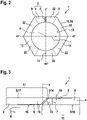
- Fig. 2 shows a top view of a sealing member 1 according to a second embodiment of the present invention.
- the sealing member 1 of the second embodiment differs from the sealing member 1 of the first embodiment in that the sealing member 1 of the second embodiment of the present invention is of a polygonal partial-ring shape.
- the sealing member 1 of the present embodiment comprises a partial ring-shaped body 2 including a slit portion 3 and a main body portion 4, wherein the main body portion 4 has a polygonal outer circumference 16.
- the inner circumference 15 is circular in this embodiment.
- each of the first half portion 11 and the second half portion 12 include a tapered portion 9.
- the tapered portion 9 is formed, for example, in one straight portion 22 of the main body portion 4.
- the tapered portions 9 are both formed in a respective half of the straight portion 22, in which the slit portion 3 is formed.
- the tapered portions 9 are formed so as to be tapered (i.e. thinner in the axial direction) towards the slit portion 3 (see also: Fig. 3 ).
- the inner circumference 15 of the main body portion 4 of the sealing member 1 of the embodiments of the present invention can also be polygon-shaped.
- Fig. 3 shows a side view of the sealing member 1 according to the first embodiment of the present invention. The following explanations can also hold true for the sealing member 1 of the second embodiment.
- the slit portion 3 of the sealing member 1 is an angle cut.
- both the first and the second embodiment of the sealing member 1 include an angle cut slit.
- the main body portion 4 comprises two tapered portions 9.
- a thickness 7 in an axial direction parallel to the central axis z varies along a circumferential direction 8 of the main body portion 4.
- the main body portion 4 is tapered towards the slit portion 3 of the partial ring-shaped body 2 in the tapered portions 9.
- the main body portion 4 comprises, as end faces with respect to the central axis z, a topmost surface 5 and a bottommost surface 6.
- the aforementioned thickness 7 in axial direction is defined as the distance between the topmost surface 5 and the bottommost surface 6.
- the bottommost surface 6 is tapered (tapered portion 9) towards the slit portion 3.
- the topmost surface 5 is tapered towards the slit portion 3.
- the tapered portions 9 encompass roughly 45° starting from the slit portion 3, of the main body portion 4.
- the respective opposite end faces 6, 5, which are opposite to the aforementioned tapered end faces 5, 6, are perpendicular to the central axis z.
- only one end face 5, 6 in each of the half portions 11, 12 is tapered, whereas the opposite end face 6, 5 is not tapered.
- an angle 19 is defined as an angle between the respective tapered end faces 5, 6, and the non-tapered end faces.
- This angle 19 is defined as an angle between the bottommost surface 6 (tapered surface) of the main body portion 4 in the tapered portion 9 of the first half portion 11 and an extension plane 18 (a theoretical plane achieved by extending the respective surface) of the bottommost surface 6 in the second half portion 12 (non-tapered surface).
- this angle 19 is also defined as an angle between the topmost surface 5 in the second half portion 12 (tapered surface) and an extension plane 17 of the topmost surface 5 in the first half portion 11 (non-tapered surface).
- the angle 19 is roughly 0.5°. It is to be understood that, although in this case they are the same, the angle 19 can be different between the first half portion 11 and the second half portion 12. With this angle 19, a maximum thickness 7 difference between the ends of the tapered portions 9 and the thickness of the non-tapered portions is 0.4 mm, i.e. the thickness 7 at the end of tapered portions 9 of the main body portion 4 is 3.3 mm.
- the bottommost surface 6 of the first half portion 11 is elastically deformed to abut against a plane surface on the bottom of Fig. 3 such that the slit portion 3 is closed.
- the gap between the ends of the main body portion 4 is closed via pressure acting on the sealing member 1 along a direction parallel to the central axis z. Therefore, fluids (to be sealed against) are at least partially hindered from passing through the slit portion 3 of the sealing member 1.
- the sealing member 1 achieves the advantageous effect of allowing for a reliable and effective seal.
- an angle 23 of the angle cut slit portion 3 is 45°, for example.
- the aforementioned advantageous effect can also be achieved if the slit portion 3 is a step cut.
- tapered portions 9 are not limited to being a linear slope, as shown in Fig. 3 . Instead, these can also be nonlinear, for example curved, wave-shaped, and/or stepped.
- Fig. 4 shows a schematic cross section of a door actuator 100 according to one embodiment of the present invention.
- the door actuator 100 is for opening and/or closing a door or damping a movement thereof.
- the door actuator 100 of this embodiment includes a spring 25, for example, and a piston mechanism including a piston 20.
- the piston mechanism is connected to a spindle 29 such that a movement of the piston 20 results in a rotation of the spindle 29, thereby opening and/or closing and/or damping a door connected to the spindle 29.
- a housing 30 of the door actuator 100 includes fluids such as air and/or hydraulic oil in inner spaces 26, 27 thereof.
- the inner spaces 26, 27 are sealed from each other, in order to prevent an escape of a fluid from one inner space (for example inner space 26) to the other (for example inner space 27).
- the piston 20 comprises a piston groove 28. Further, a sealing member 1 according to the foregoing embodiments is inserted into the piston groove 28.
- the door actuator 100 may comprise a plurality of pistons 20. Further, the piston(s) 20 of the door actuator 100 may each also comprise a plurality of piston grooves 28, and respectively a plurality of sealing members 1.
- the sealing member 1 can thus be easily inserted into the piston groove 28, while also achieving an effective and reliable sealing effect.
- sealing member 1 is not restricted to sealing pistons 20 or piston grooves 28.
- the sealing member 1 can also seal valves or other openings in fluid-filled elements, such as housings 30 of door actuators 100.
Landscapes
- Engineering & Computer Science (AREA)
- General Engineering & Computer Science (AREA)
- Mechanical Engineering (AREA)
- Sealing Devices (AREA)
- Gasket Seals (AREA)
- Actuator (AREA)
Abstract
The invention concerns a sealing member (1), especially for sealing a piston (20). The sealing member (1) comprises a partial ring-shaped body (2) including a slit portion (3) and a main body portion (4), wherein the ring-shaped body (2) extends annularly about a central axis (z) and a radial axis (r) is defined perpendicular to the central axis (z). Further, the main body portion (4) comprises, as end faces with respect to the central axis (z), a topmost surface (5) and a bottommost surface (6). A thickness (7) in an axial direction parallel to the central axis (z) of the main body portion (4) between the topmost surface (5) and the bottommost surface (6) varies along a circumferential direction (8) of the main body portion (4). The invention also concerns a door actuator (100) including the sealing member (1).
Description
- The invention concerns a sealing member, especially for sealing a piston, and a door actuator for opening and/or closing a door.
- Conventionally, ring-shaped sealing members for sealing pistons (also known as "piston rings") are known. Such conventional sealing members are commonly provided with a slit for easy insertion into a groove, especially a groove of a piston to be sealed by the sealing member. Although these provide easy insertion, they commonly have a problem of not sufficiently sealing the piston. In particular, when the fluids in a cylinder in which the piston is provided are under pressure, they can circumvent the sealing member by flowing through the slit thereof. Therefore, conventional sealing members commonly do not provide a sufficient seal.
- An object of the present invention is to provide a sealing member which can provide a sufficient sealing effect while also being easy to install and/or remove.
- This object is solved by the features of the independent claim. The dependent claims contain advantageous embodiments of the present invention.
- A sealing member, especially for sealing a piston, of the present invention comprises a partial ring-shaped body. The partial ring-shaped body includes a slit portion and a main body portion. Therein, the partial ring-shaped body extends annularly about a central axis. Further, a radial axis is defined as being perpendicular to the central axis. The main body comprises, as end faces with respect to the central axis, a topmost surface and a bottommost surface. Further, a thickness in an axial direction, which is parallel to the central axis, of the main body between the topmost surface and the bottommost surface varies along a circumferential direction of the main body portion. In other words, the thickness of the main body portion is not constant along the circumferential direction of the main body portion.
- The sealing member of the present invention has the advantage that a pressure acting on the sealing member, especially in an axial direction of the sealing member, can elastically deform the sealing member in order to close a gap of the slit portion such that fluids cannot pass therethrough. Therefore, the sealing member of the present invention provides a more reliable and sufficient sealing effect, while also being easy to insert.
- In the above and the following, the terms "ring-shaped" and/or "partial ring-shaped" are to be understood as meaning a shape corresponding at least in part substantially to a circle-shape, wherein the shape thereof is not necessarily limited to being a round shape. For example, the "ring-shape" can be a round ring, or a polygonal ring. For example, an (in a radial direction) outer circumference of the "ring-shape" may be round or polygonal and/or an inner circumference thereof may be round or also polygonal. Of course, a combination of round and/or polygonal portions of one or both inner and outer circumferences is also possible. Further, "partial ring-shaped" is to be understood as a substantially open ring shape. For instance, a ring (circular or polygonal) with a slit may be understood as "partial ring-shaped". This shape pertains to a relaxed, not installed state of the sealing member.
- Preferably, the main body portion of the sealing member comprises at least one tapered portion. In the tapered portion, the thickness in the axial direction of the main body portion is tapered along the circumferential direction of the main body portion. Thereby, the thickness of the main body portion gradually varies along the circumferential direction thereof. This provides the advantage that a pressure acting on the sealing member can advantageously be distributed in an even manner in order to close the slit portion of the sealing member, thereby providing a better sealing effect.
- Advantageously, the tapered portion of the main body portion is tapered towards the slit portion of the partial ring-shaped body. In other words, a thinner part of the tapered portion is closer to the slit portion than a thicker part of the tapered portion. This provides an especially reliable sealing effect of the sealing member.
- Further preferably, the tapered portion extends, in the circumferential direction of the main body portion, from the slit portion in a range of a minimum and/or a maximum of a fraction of a circumference of the partial ring-shaped body. Therein, the minimum is preferably one twentieth, more preferably one tenth, even more preferably one eighth. In addition or alternatively, the maximum is preferably one half, more preferably one quarter, even more preferably one sixth. In other words, as an example of these foregoing values, a circumferential length of the tapered portion, starting from the slit portion, is preferably between and including one twentieth and one half of the circumference of the partial ring-shaped body. This has the advantageous effect of providing a sealing member with a reliable and effective sealing effect.
- In another advantageous embodiment, the main body portion of the sealing member preferably comprises, in the circumferential direction, a first half portion and a second half portion. Therein, the first half portion and the second half portion extend to the slit portion from a point of the main body portion that is opposite to the slit portion. The first half portion and the second half portion each include one tapered portion. In other words, the sealing member preferably includes two tapered portions, one in each half portion of the main body portion thereof. This provides an advantageously effective sealing effect of the sealing member.
- Advantageously, an extension plane of the topmost surface of the main body portion is perpendicular to the axial direction in the first half portion of the main body portion. Further, in the second half portion, an extension plane of the bottommost surface of the main body portion is perpendicular to the axial direction. This has the advantage that the sealing member can provide an effective and reliable sealing effect.
- Preferably, an angle between the bottommost surface of the main body portion in the tapered portion of the first half portion and the extension plane of the bottommost surface in the second half portion is in a range of a minimum and a maximum. In addition or alternatively, an angle between the topmost surface of the main body portion in the tapered portion of the second half portion and the extension plane of the topmost surface in the first half portion is in a range of the minimum and the maximum. Therein, the minimum is preferably 0.25°, more preferably 0.5°, even more preferably 1°. In addition or alternatively, the maximum is preferably 5°, more preferably 2.5°, even more preferably 1.5°, further preferably 1.25°. In other words, one or both of the aforementioned angles is preferably in a range between and including, as a preferable example, 0.25° and 5°. As a preferable example, both aforementioned angles are 0.5°. These values further advantageously promote an effective and reliable sealing effect.
- Further advantageously, a thickness along the radial axis of the partial ring-shaped body between an inner circumference and an outer circumference of the main body portion is constant along the circumferential direction. In other words, the entire main body portion can preferably have a substantially constant thickness along the circumferential direction, the constant thickness being with respect to the radial direction of the partial ring-shaped body. This further advantageously promotes an effective and reliable sealing effect.
- Preferably, the slit portion may be an angle cut and/or a step cut. This allows for easy insertion of the sealing member while also providing an effective and reliable sealing effect.
- The present invention also concerns a door actuator for opening and/or closing a door. The door actuator comprises a piston for actuating the door and at least one sealing member according to any one of the foregoing advantageous embodiments. Therein, the piston includes at least one piston groove respectively configured to receive the sealing member. The door actuator may preferably comprise a plurality of pistons, wherein each piston may comprise one or more piston grooves and respective sealing members. The sealing members may be employed as so-called "piston rings".
- The sealing member may be made of or comprise metal and/or a plastic and/or a rubber material.
- Further details, advantages, and features of preferred embodiments of the present invention are described in detail with reference to the figures.
- Therein,
-
Fig. 1 shows a top view of a sealing member according to one embodiment of the present invention, -
Fig. 2 shows a top view of a sealing member according to a second embodiment of the present invention, -
Fig. 3 shows a side view of the sealing member according to the first embodiment of the present invention, and -
Fig. 4 shows a schematic cross section of a door actuator according to one embodiment of the present invention. -
Fig. 1 shows a top view of a sealingmember 1 according to one embodiment of the present invention. More specifically,fig. 1 shows the sealingmember 1 in a relaxed state before being installed or after being removed from another element that is to be sealed by the sealingmember 1. For instance (see alsoFig. 4 ), the sealingmember 1 may seal a piston as another element. - Therein, the sealing
member 1 comprises a partial ring-shapedbody 2. The partial ring-shapedbody 2 includes aslit portion 3 and amain body portion 4. In other words, the sealingmember 1 is a slit ring. - In the present embodiment, the sealing
member 1 is a slit circular ring. - The
slit portion 3 of the partial ring-shapedbody 2 is defined as a gap between ends of themain body portion 4, without including the aforementioned ends of themain body portion 4. In the same sense, themain body portion 4 does not include theslit portion 3. As can be seen from a comparison withFig. 3 , theslit portion 3, or rather the slit thereof, is an angle cut. - The following axes and directions are defined with respect to the sealing member 1: A central axis z is defined which is surrounded by the ring-shaped
body 2. In other words, the ring-shapedbody 2 extends annularly about the central axis z. Further, a radial axis r is defined which is perpendicular to the central axis z. Acircumferential direction 8 is defined as a direction along a circumference 10 of the partial ring-shapedbody 2. - A circumference 10 is defined as the length of an outer circumference 16 of the partial ring-shaped
body 2 including themain body portion 4 and the slit portion 3 (calculated simply as 2 x π x r, wherein r is an outer radius of themain body portion 4 in the case of a circular partial ring-shaped body 2). - The partial ring-shaped
body 2 has athickness 13 along the radial axis r (radial thickness) between aninner circumference 15 and an outer circumference 16 of themain body portion 4. As can be taken fromFig. 1 , the sealingmember 1 of this embodiment has aconstant radial thickness 13 along thecircumferential direction 6. That is, theradial thickness 13 of the partial ring-shapedbody 2 is the same over the entire circumference 10 thereof. - Further, a
first half portion 11 and asecond half portion 12 are defined as two halves of themain body portion 4. Therein, therespective halves main body portion 4 are defined as extending to theslit portion 3 from apoint 14 opposite (180°) to theslit portion 3. - As will be described with respect to
Fig. 3 , each of thehalves main body portion 4 of the sealingmember 1 according to this embodiment include a tapered portion 9 (not visible in top view). In the taperedportion 9, athickness 7 in the axial direction parallel to the central axis z of themain body portion 4 varies along thecircumferential direction 8 of themain body portion 4. - Starting from the
slit portion 3, i.e. 0°, each of thetapered portions 9 extends to roughly 45° of themain body portion 4. In other words, thethickness 7 in the axial direction (see:Fig. 3 ) of themain body portion 4 increases starting from 0° up to and including 45°. Between and including 45° and 180°, each of thehalf portions main body portion 4 has a constant thickness 7 (see:Fig. 3 ) in axial direction (parallel to central axis z). - In this specific example, although not limited thereto, the
thickness 13 in the radial direction r of themain body portion 4 is 3.2 mm. Further, aninner diameter 24 of themain body portion 4 is 32 mm. Thethickness 7 in the central axis z direction (see:Fig. 3 ) in the non-tapered portions of themain body portion 4 is 3.7 mm. -
Fig. 2 shows a top view of a sealingmember 1 according to a second embodiment of the present invention. - As can be taken from
Fig. 2 , the sealingmember 1 of the second embodiment differs from the sealingmember 1 of the first embodiment in that the sealingmember 1 of the second embodiment of the present invention is of a polygonal partial-ring shape. In other words, the sealingmember 1 of the present embodiment comprises a partial ring-shapedbody 2 including aslit portion 3 and amain body portion 4, wherein themain body portion 4 has a polygonal outer circumference 16. Theinner circumference 15 is circular in this embodiment. - In this embodiment, each of the
first half portion 11 and thesecond half portion 12 include a taperedportion 9. Herein, the taperedportion 9 is formed, for example, in onestraight portion 22 of themain body portion 4. In particular, thetapered portions 9 are both formed in a respective half of thestraight portion 22, in which theslit portion 3 is formed. Thetapered portions 9 are formed so as to be tapered (i.e. thinner in the axial direction) towards the slit portion 3 (see also:Fig. 3 ). - Of course, the
inner circumference 15 of themain body portion 4 of the sealingmember 1 of the embodiments of the present invention can also be polygon-shaped. In addition, it is possible that only portions of the outer circumference 16 and/or theinner circumference 15 of themain body portion 4 is circular or polygonal-shaped. -
Fig. 3 shows a side view of the sealingmember 1 according to the first embodiment of the present invention. The following explanations can also hold true for the sealingmember 1 of the second embodiment. - As can be taken from
Fig. 3 , theslit portion 3 of the sealingmember 1 is an angle cut. In this case, both the first and the second embodiment of the sealingmember 1 include an angle cut slit. - Further, the
main body portion 4 comprises two taperedportions 9. In thetapered portions 9, athickness 7 in an axial direction parallel to the central axis z varies along acircumferential direction 8 of themain body portion 4. - More specifically, the
main body portion 4 is tapered towards theslit portion 3 of the partial ring-shapedbody 2 in thetapered portions 9. - These
tapered portions 9 are described as follows. Themain body portion 4 comprises, as end faces with respect to the central axis z, atopmost surface 5 and abottommost surface 6. Theaforementioned thickness 7 in axial direction is defined as the distance between thetopmost surface 5 and thebottommost surface 6. In the first half 11 (see:Figs. 1 and2 ), thebottommost surface 6 is tapered (tapered portion 9) towards theslit portion 3. In thesecond half portion 12, thetopmost surface 5 is tapered towards theslit portion 3. As can be seen inFig. 3 , thetapered portions 9 encompass roughly 45° starting from theslit portion 3, of themain body portion 4. In addition, in thefirst half portion 11 and thesecond half portion 12, the respective opposite end faces 6, 5, which are opposite to the aforementioned tapered end faces 5, 6, are perpendicular to the central axis z. In other words, only oneend face half portions opposite end face - Further, an
angle 19 is defined as an angle between the respective tapered end faces 5, 6, and the non-tapered end faces. Thisangle 19 is defined as an angle between the bottommost surface 6 (tapered surface) of themain body portion 4 in the taperedportion 9 of thefirst half portion 11 and an extension plane 18 (a theoretical plane achieved by extending the respective surface) of thebottommost surface 6 in the second half portion 12 (non-tapered surface). Likewise, thisangle 19 is also defined as an angle between thetopmost surface 5 in the second half portion 12 (tapered surface) and an extension plane 17 of thetopmost surface 5 in the first half portion 11 (non-tapered surface). - In this specific example, the
angle 19 is roughly 0.5°. It is to be understood that, although in this case they are the same, theangle 19 can be different between thefirst half portion 11 and thesecond half portion 12. With thisangle 19, amaximum thickness 7 difference between the ends of thetapered portions 9 and the thickness of the non-tapered portions is 0.4 mm, i.e. thethickness 7 at the end of taperedportions 9 of themain body portion 4 is 3.3 mm. - When a pressure acts on the sealing
member 1, for instance in a bottom-to-top direction inFig. 3 , due to the taperedportion 9 in thesecond half portion 12 of themain body portion 4, themain body portion 4 can elastically deform to abut against an especially plane surface (for instance, an inner surface of a groove formed in a piston) with its topmost surfaces 5 (of bothhalf portions 11, 12). Due to this elastic movement of thesecond half portion 12 in the upwards direction inFig. 3 , theslit portion 3 is closed. The same effect is achieved when a pressure acts on the sealingmember 1 in an opposite, i.e. top-to-bottom direction. Therein, thebottommost surface 6 of thefirst half portion 11 is elastically deformed to abut against a plane surface on the bottom ofFig. 3 such that theslit portion 3 is closed. In other words, the gap between the ends of themain body portion 4 is closed via pressure acting on the sealingmember 1 along a direction parallel to the central axis z. Therefore, fluids (to be sealed against) are at least partially hindered from passing through theslit portion 3 of the sealingmember 1. - Thereby, the sealing
member 1 achieves the advantageous effect of allowing for a reliable and effective seal. - In the foregoing embodiments, an
angle 23 of the angle cut slitportion 3 is 45°, for example. The aforementioned advantageous effect can also be achieved if theslit portion 3 is a step cut. - In addition, it is to be understood that the
tapered portions 9 are not limited to being a linear slope, as shown inFig. 3 . Instead, these can also be nonlinear, for example curved, wave-shaped, and/or stepped. -
Fig. 4 shows a schematic cross section of adoor actuator 100 according to one embodiment of the present invention. Thedoor actuator 100 is for opening and/or closing a door or damping a movement thereof. For this, thedoor actuator 100 of this embodiment includes aspring 25, for example, and a piston mechanism including apiston 20. Therein, the piston mechanism is connected to aspindle 29 such that a movement of thepiston 20 results in a rotation of thespindle 29, thereby opening and/or closing and/or damping a door connected to thespindle 29. - A
housing 30 of thedoor actuator 100 includes fluids such as air and/or hydraulic oil ininner spaces piston 20 to function properly, theinner spaces - In order to be sealed properly, the
piston 20 comprises apiston groove 28. Further, a sealingmember 1 according to the foregoing embodiments is inserted into thepiston groove 28. - When a pressure, for instance by a fluid in the
inner space 26, acts on thepiston 20, in particular on the sealingmember 1 in thepiston groove 28, the sealingmember 1 is pressed against aninner wall 31 of thepiston groove 28. Thereby, as described above, the sealingmember 1 is elastically deformed and the gap due to theslot portion 3 thereof is closed, thus preventing a leak of fluids. - The
door actuator 100 may comprise a plurality ofpistons 20. Further, the piston(s) 20 of thedoor actuator 100 may each also comprise a plurality ofpiston grooves 28, and respectively a plurality of sealingmembers 1. - The sealing
member 1 can thus be easily inserted into thepiston groove 28, while also achieving an effective and reliable sealing effect. - It is to be understood that the sealing
member 1 is not restricted to sealingpistons 20 orpiston grooves 28. For example, the sealingmember 1 can also seal valves or other openings in fluid-filled elements, such ashousings 30 ofdoor actuators 100. -
- 1
- sealing member
- 2
- partial ring-shaped body
- 3
- slit portion
- 4
- main body portion
- 5
- topmost surface
- 6
- bottommost surface
- 7
- thickness in central axis direction
- 8
- circumferential direction
- 9
- tapered portion
- 10
- circumference of the partial ring-shaped body
- 11
- first half portion
- 12
- second half portion
- 13
- thickness along radial axis
- 14
- point opposite to slit portion
- 15
- inner circumference
- 16
- outer circumference
- 17
- extension plane of topmost surface
- 18
- extension plane of bottommost surface
- 19
- angle
- 20
- piston
- 22
- straight portion of main body portion
- 23
- angle
- 24
- inner diameter of main body portion
- 25
- spring
- 26, 27
- inner spaces
- 28
- piston groove
- 29
- spindle
- 30
- housing of door actuator
- 31
- inner wall of piston groove
- 100
- door actuator
- z
- central axis
- r
- radial axis
Claims (10)
- Sealing member (1), especially for sealing a piston (20), comprising:• a partial ring-shaped body (2) including a slit portion (3) and a main body portion (4), wherein the partial ring-shaped body (2) extends annularly about a central axis (z) and a radial axis (r) is defined perpendicular to the central axis (z),• the main body portion (4) comprises, as end faces with respect to the central axis (z), a topmost surface (5) and a bottommost surface (6), and• a thickness (7) in an axial direction parallel to the central axis (z) of the main body portion (4) between the topmost surface (5) and the bottommost surface (6) varies along a circumferential direction (8) of the main body portion (4).
- Sealing member (1) according to claim 1, wherein the main body portion (4) comprises at least one tapered portion (9), wherein the thickness (7) in the axial direction (z) of the main body portion (4) in the tapered portion (9) is tapered along the circumferential direction (8) of the main body portion (4).
- Sealing member (1) according to claim 2, wherein the tapered portion (9) of the main body portion (4) is tapered towards the slit portion (3) of the partial ring-shaped body (2).
- Sealing member (1) according to claim 2 or 3, wherein the tapered portion (9) extends, in the circumferential direction (8) of the main body portion (4), from the slit portion (3) in a range of a minimum and/or a maximum of a fraction of a circumference (10) of the partial ring-shaped body (2), wherein the minimum is one twentieth, preferably one tenth, more preferably one eighth and/or the maximum is one half, preferably one quarter, more preferably one sixth.
- Sealing member (1) according to any one of claims 2 to 4, wherein the main body portion (4) comprises, in the circumferential direction (8), a first half portion (11) and a second half portion (12), the first half portion (11) and the second half portion (12) extending to the slit portion (3) from a point (14) of the main body portion (4) opposite to the slit portion (3), and the first half portion (11) and the second half portion (12) respectively include one tapered portion (9).
- Sealing member (1) according to claim 5, wherein, in the first half portion (11), an extension plane (17) of the topmost surface (5) of the main body portion (4) is perpendicular to the axial direction, and, in the second half portion (12), an extension plane (18) of the bottommost surface (6) of the main body portion (4) is perpendicular to the axial direction.
- Sealing member (1) according to claim 6, wherein an angle (19) between the bottommost surface (6) of the main body portion (4) in the tapered portion (9) of the first half portion (11) and the extension plane (18) of the bottommost surface (6) in the second half portion (12) and/or an angle (19) between the topmost surface (5) of the main body portion (4) in the tapered portion (9) of the second half portion (12) and the extension plane (17) of the topmost surface (5) in the first half portion (11) is in a range of a minimum and a maximum, wherein the minimum is 0.25°, preferably 0.5°, more preferably 1° and/or the maximum is 5°, preferably 2.5°, more preferably 1.5°, more preferably 1.25°.
- Sealing member (1) according to any one of the foregoing claims, wherein a thickness (13) along the radial axis (r) of the partial ring-shaped body (2) between an inner circumference (15) and an outer circumference (16) of the main body portion (4) is constant along the circumferential direction (8).
- Sealing member (1) according to any one of the foregoing claims, wherein the slit portion (3) is an angle cut and/or a step cut.
- A door actuator (100) for opening and/or closing a door, comprising:• at least one piston (20) for actuating the door; and• at least one sealing member (1) according to any one of the foregoing claims, wherein• the at least one piston (20) includes at least one piston groove (28) respectively configured to receive the sealing member (1).
Priority Applications (4)
| Application Number | Priority Date | Filing Date | Title |
|---|---|---|---|
| EP21171365.6A EP4083476A1 (en) | 2021-04-29 | 2021-04-29 | Sealing member and door actuator |
| CN202210356468.9A CN115264060A (en) | 2021-04-29 | 2022-04-06 | Sealing member and door actuator |
| TW111114081A TW202300773A (en) | 2021-04-29 | 2022-04-13 | Sealing member and door actuator |
| KR1020220048608A KR20220148730A (en) | 2021-04-29 | 2022-04-20 | Sealing member and door actuator |
Applications Claiming Priority (1)
| Application Number | Priority Date | Filing Date | Title |
|---|---|---|---|
| EP21171365.6A EP4083476A1 (en) | 2021-04-29 | 2021-04-29 | Sealing member and door actuator |
Publications (1)
| Publication Number | Publication Date |
|---|---|
| EP4083476A1 true EP4083476A1 (en) | 2022-11-02 |
Family
ID=75746353
Family Applications (1)
| Application Number | Title | Priority Date | Filing Date |
|---|---|---|---|
| EP21171365.6A Withdrawn EP4083476A1 (en) | 2021-04-29 | 2021-04-29 | Sealing member and door actuator |
Country Status (4)
| Country | Link |
|---|---|
| EP (1) | EP4083476A1 (en) |
| KR (1) | KR20220148730A (en) |
| CN (1) | CN115264060A (en) |
| TW (1) | TW202300773A (en) |
Citations (3)
| Publication number | Priority date | Publication date | Assignee | Title |
|---|---|---|---|---|
| GB1338189A (en) * | 1971-05-18 | 1973-11-21 | Ver Baubeschlag Gretsch Co | Arrangements for creating seals between surfaces and elements moving relative thereto |
| US5275422A (en) * | 1989-03-31 | 1994-01-04 | Leber Corporation | Sealing assembly |
| EP3546805A1 (en) * | 2018-03-28 | 2019-10-02 | Federal-Mogul Göteborg AB | A piston ring |
-
2021
- 2021-04-29 EP EP21171365.6A patent/EP4083476A1/en not_active Withdrawn
-
2022
- 2022-04-06 CN CN202210356468.9A patent/CN115264060A/en active Pending
- 2022-04-13 TW TW111114081A patent/TW202300773A/en unknown
- 2022-04-20 KR KR1020220048608A patent/KR20220148730A/en active Pending
Patent Citations (3)
| Publication number | Priority date | Publication date | Assignee | Title |
|---|---|---|---|---|
| GB1338189A (en) * | 1971-05-18 | 1973-11-21 | Ver Baubeschlag Gretsch Co | Arrangements for creating seals between surfaces and elements moving relative thereto |
| US5275422A (en) * | 1989-03-31 | 1994-01-04 | Leber Corporation | Sealing assembly |
| EP3546805A1 (en) * | 2018-03-28 | 2019-10-02 | Federal-Mogul Göteborg AB | A piston ring |
Also Published As
| Publication number | Publication date |
|---|---|
| CN115264060A (en) | 2022-11-01 |
| KR20220148730A (en) | 2022-11-07 |
| TW202300773A (en) | 2023-01-01 |
Similar Documents
| Publication | Publication Date | Title |
|---|---|---|
| EP3312482B1 (en) | Seal assemblies for extreme temperatures and related methods | |
| EP1960632B1 (en) | End closure device for a turbomachine casing | |
| US9016746B2 (en) | Train axle assembly | |
| EP1818562B1 (en) | Gas spring | |
| US2373628A (en) | Spherical plug valve | |
| US4513765A (en) | Arrangement on a butterfly valve | |
| EP1696154B1 (en) | Dynamic seal | |
| EP0184285A2 (en) | Ring seals | |
| WO2012078583A2 (en) | Ring seal retainer assembly and methods | |
| US5913521A (en) | Rotating seal ring component kit for a mechanical split seal | |
| AU2020202496B2 (en) | Annular sealing assembly | |
| US20090038119A1 (en) | Friction hinge without applied grease | |
| WO2008100540A1 (en) | Ring seal and retainer assembly | |
| NO341722B1 (en) | Multi-component diffuser assembly | |
| US5967525A (en) | Drive mechanism for a rotating mechanical split seal and method of assembly thereof | |
| EP3771849A1 (en) | Multiple piece seal ring assembly | |
| CN108779861B (en) | Asymmetrical seal ring | |
| EP4103866B1 (en) | Shaft mounting assembly | |
| US12110966B2 (en) | Self-retaining lip seal | |
| KR20220148730A (en) | Sealing member and door actuator | |
| CN115720604A (en) | Central valve for camshaft phaser | |
| EP0542530A1 (en) | Seal | |
| KR102301382B1 (en) | valve | |
| CN108692045A (en) | Seal assembly for industrial sluice valves and the valve including the seal assembly | |
| US12392411B2 (en) | Seal arrangement with low drag seal gland |
Legal Events
| Date | Code | Title | Description |
|---|---|---|---|
| PUAI | Public reference made under article 153(3) epc to a published international application that has entered the european phase |
Free format text: ORIGINAL CODE: 0009012 |
|
| STAA | Information on the status of an ep patent application or granted ep patent |
Free format text: STATUS: THE APPLICATION HAS BEEN PUBLISHED |
|
| AK | Designated contracting states |
Kind code of ref document: A1 Designated state(s): AL AT BE BG CH CY CZ DE DK EE ES FI FR GB GR HR HU IE IS IT LI LT LU LV MC MK MT NL NO PL PT RO RS SE SI SK SM TR |
|
| STAA | Information on the status of an ep patent application or granted ep patent |
Free format text: STATUS: THE APPLICATION IS DEEMED TO BE WITHDRAWN |
|
| 18D | Application deemed to be withdrawn |
Effective date: 20230503 |