EP4083453A1 - Rolling bearing for air turbine - Google Patents
Rolling bearing for air turbine Download PDFInfo
- Publication number
- EP4083453A1 EP4083453A1 EP20905217.4A EP20905217A EP4083453A1 EP 4083453 A1 EP4083453 A1 EP 4083453A1 EP 20905217 A EP20905217 A EP 20905217A EP 4083453 A1 EP4083453 A1 EP 4083453A1
- Authority
- EP
- European Patent Office
- Prior art keywords
- seal member
- ring
- inner ring
- peripheral surface
- contact
- Prior art date
- Legal status (The legal status is an assumption and is not a legal conclusion. Google has not performed a legal analysis and makes no representation as to the accuracy of the status listed.)
- Granted
Links
Images



Classifications
-
- F—MECHANICAL ENGINEERING; LIGHTING; HEATING; WEAPONS; BLASTING
- F16—ENGINEERING ELEMENTS AND UNITS; GENERAL MEASURES FOR PRODUCING AND MAINTAINING EFFECTIVE FUNCTIONING OF MACHINES OR INSTALLATIONS; THERMAL INSULATION IN GENERAL
- F16J—PISTONS; CYLINDERS; SEALINGS
- F16J15/00—Sealings
- F16J15/16—Sealings between relatively-moving surfaces
- F16J15/32—Sealings between relatively-moving surfaces with elastic sealings, e.g. O-rings
- F16J15/3204—Sealings between relatively-moving surfaces with elastic sealings, e.g. O-rings with at least one lip
- F16J15/3228—Sealings between relatively-moving surfaces with elastic sealings, e.g. O-rings with at least one lip formed by deforming a flat ring
-
- F—MECHANICAL ENGINEERING; LIGHTING; HEATING; WEAPONS; BLASTING
- F16—ENGINEERING ELEMENTS AND UNITS; GENERAL MEASURES FOR PRODUCING AND MAINTAINING EFFECTIVE FUNCTIONING OF MACHINES OR INSTALLATIONS; THERMAL INSULATION IN GENERAL
- F16C—SHAFTS; FLEXIBLE SHAFTS; ELEMENTS OR CRANKSHAFT MECHANISMS; ROTARY BODIES OTHER THAN GEARING ELEMENTS; BEARINGS
- F16C33/00—Parts of bearings; Special methods for making bearings or parts thereof
- F16C33/72—Sealings
- F16C33/76—Sealings of ball or roller bearings
- F16C33/78—Sealings of ball or roller bearings with a diaphragm, disc, or ring, with or without resilient members
- F16C33/7816—Details of the sealing or parts thereof, e.g. geometry, material
- F16C33/782—Details of the sealing or parts thereof, e.g. geometry, material of the sealing region
- F16C33/7826—Details of the sealing or parts thereof, e.g. geometry, material of the sealing region of the opposing surface cooperating with the seal, e.g. a shoulder surface of a bearing ring
-
- F—MECHANICAL ENGINEERING; LIGHTING; HEATING; WEAPONS; BLASTING
- F16—ENGINEERING ELEMENTS AND UNITS; GENERAL MEASURES FOR PRODUCING AND MAINTAINING EFFECTIVE FUNCTIONING OF MACHINES OR INSTALLATIONS; THERMAL INSULATION IN GENERAL
- F16C—SHAFTS; FLEXIBLE SHAFTS; ELEMENTS OR CRANKSHAFT MECHANISMS; ROTARY BODIES OTHER THAN GEARING ELEMENTS; BEARINGS
- F16C33/00—Parts of bearings; Special methods for making bearings or parts thereof
- F16C33/72—Sealings
- F16C33/76—Sealings of ball or roller bearings
- F16C33/78—Sealings of ball or roller bearings with a diaphragm, disc, or ring, with or without resilient members
- F16C33/7816—Details of the sealing or parts thereof, e.g. geometry, material
- F16C33/782—Details of the sealing or parts thereof, e.g. geometry, material of the sealing region
- F16C33/7823—Details of the sealing or parts thereof, e.g. geometry, material of the sealing region of sealing lips
-
- F—MECHANICAL ENGINEERING; LIGHTING; HEATING; WEAPONS; BLASTING
- F16—ENGINEERING ELEMENTS AND UNITS; GENERAL MEASURES FOR PRODUCING AND MAINTAINING EFFECTIVE FUNCTIONING OF MACHINES OR INSTALLATIONS; THERMAL INSULATION IN GENERAL
- F16C—SHAFTS; FLEXIBLE SHAFTS; ELEMENTS OR CRANKSHAFT MECHANISMS; ROTARY BODIES OTHER THAN GEARING ELEMENTS; BEARINGS
- F16C33/00—Parts of bearings; Special methods for making bearings or parts thereof
- F16C33/72—Sealings
- F16C33/76—Sealings of ball or roller bearings
- F16C33/78—Sealings of ball or roller bearings with a diaphragm, disc, or ring, with or without resilient members
- F16C33/7816—Details of the sealing or parts thereof, e.g. geometry, material
- F16C33/783—Details of the sealing or parts thereof, e.g. geometry, material of the mounting region
-
- F—MECHANICAL ENGINEERING; LIGHTING; HEATING; WEAPONS; BLASTING
- F16—ENGINEERING ELEMENTS AND UNITS; GENERAL MEASURES FOR PRODUCING AND MAINTAINING EFFECTIVE FUNCTIONING OF MACHINES OR INSTALLATIONS; THERMAL INSULATION IN GENERAL
- F16C—SHAFTS; FLEXIBLE SHAFTS; ELEMENTS OR CRANKSHAFT MECHANISMS; ROTARY BODIES OTHER THAN GEARING ELEMENTS; BEARINGS
- F16C33/00—Parts of bearings; Special methods for making bearings or parts thereof
- F16C33/72—Sealings
- F16C33/76—Sealings of ball or roller bearings
- F16C33/78—Sealings of ball or roller bearings with a diaphragm, disc, or ring, with or without resilient members
- F16C33/784—Sealings of ball or roller bearings with a diaphragm, disc, or ring, with or without resilient members mounted to a groove in the inner surface of the outer race and extending toward the inner race
- F16C33/7843—Sealings of ball or roller bearings with a diaphragm, disc, or ring, with or without resilient members mounted to a groove in the inner surface of the outer race and extending toward the inner race with a single annular sealing disc
- F16C33/7853—Sealings of ball or roller bearings with a diaphragm, disc, or ring, with or without resilient members mounted to a groove in the inner surface of the outer race and extending toward the inner race with a single annular sealing disc with one or more sealing lips to contact the inner race
- F16C33/7856—Sealings of ball or roller bearings with a diaphragm, disc, or ring, with or without resilient members mounted to a groove in the inner surface of the outer race and extending toward the inner race with a single annular sealing disc with one or more sealing lips to contact the inner race with a single sealing lip
-
- F—MECHANICAL ENGINEERING; LIGHTING; HEATING; WEAPONS; BLASTING
- F16—ENGINEERING ELEMENTS AND UNITS; GENERAL MEASURES FOR PRODUCING AND MAINTAINING EFFECTIVE FUNCTIONING OF MACHINES OR INSTALLATIONS; THERMAL INSULATION IN GENERAL
- F16J—PISTONS; CYLINDERS; SEALINGS
- F16J15/00—Sealings
- F16J15/16—Sealings between relatively-moving surfaces
- F16J15/32—Sealings between relatively-moving surfaces with elastic sealings, e.g. O-rings
- F16J15/3268—Mounting of sealing rings
-
- F—MECHANICAL ENGINEERING; LIGHTING; HEATING; WEAPONS; BLASTING
- F16—ENGINEERING ELEMENTS AND UNITS; GENERAL MEASURES FOR PRODUCING AND MAINTAINING EFFECTIVE FUNCTIONING OF MACHINES OR INSTALLATIONS; THERMAL INSULATION IN GENERAL
- F16C—SHAFTS; FLEXIBLE SHAFTS; ELEMENTS OR CRANKSHAFT MECHANISMS; ROTARY BODIES OTHER THAN GEARING ELEMENTS; BEARINGS
- F16C19/00—Bearings with rolling contact, for exclusively rotary movement
- F16C19/02—Bearings with rolling contact, for exclusively rotary movement with bearing balls essentially of the same size in one or more circular rows
- F16C19/04—Bearings with rolling contact, for exclusively rotary movement with bearing balls essentially of the same size in one or more circular rows for radial load mainly
- F16C19/06—Bearings with rolling contact, for exclusively rotary movement with bearing balls essentially of the same size in one or more circular rows for radial load mainly with a single row or balls
-
- F—MECHANICAL ENGINEERING; LIGHTING; HEATING; WEAPONS; BLASTING
- F16—ENGINEERING ELEMENTS AND UNITS; GENERAL MEASURES FOR PRODUCING AND MAINTAINING EFFECTIVE FUNCTIONING OF MACHINES OR INSTALLATIONS; THERMAL INSULATION IN GENERAL
- F16C—SHAFTS; FLEXIBLE SHAFTS; ELEMENTS OR CRANKSHAFT MECHANISMS; ROTARY BODIES OTHER THAN GEARING ELEMENTS; BEARINGS
- F16C2202/00—Solid materials defined by their properties
- F16C2202/02—Mechanical properties
- F16C2202/04—Hardness
-
- F—MECHANICAL ENGINEERING; LIGHTING; HEATING; WEAPONS; BLASTING
- F16—ENGINEERING ELEMENTS AND UNITS; GENERAL MEASURES FOR PRODUCING AND MAINTAINING EFFECTIVE FUNCTIONING OF MACHINES OR INSTALLATIONS; THERMAL INSULATION IN GENERAL
- F16C—SHAFTS; FLEXIBLE SHAFTS; ELEMENTS OR CRANKSHAFT MECHANISMS; ROTARY BODIES OTHER THAN GEARING ELEMENTS; BEARINGS
- F16C2226/00—Joining parts; Fastening; Assembling or mounting parts
- F16C2226/50—Positive connections
-
- F—MECHANICAL ENGINEERING; LIGHTING; HEATING; WEAPONS; BLASTING
- F16—ENGINEERING ELEMENTS AND UNITS; GENERAL MEASURES FOR PRODUCING AND MAINTAINING EFFECTIVE FUNCTIONING OF MACHINES OR INSTALLATIONS; THERMAL INSULATION IN GENERAL
- F16C—SHAFTS; FLEXIBLE SHAFTS; ELEMENTS OR CRANKSHAFT MECHANISMS; ROTARY BODIES OTHER THAN GEARING ELEMENTS; BEARINGS
- F16C2240/00—Specified values or numerical ranges of parameters; Relations between them
- F16C2240/30—Angles, e.g. inclinations
-
- F—MECHANICAL ENGINEERING; LIGHTING; HEATING; WEAPONS; BLASTING
- F16—ENGINEERING ELEMENTS AND UNITS; GENERAL MEASURES FOR PRODUCING AND MAINTAINING EFFECTIVE FUNCTIONING OF MACHINES OR INSTALLATIONS; THERMAL INSULATION IN GENERAL
- F16C—SHAFTS; FLEXIBLE SHAFTS; ELEMENTS OR CRANKSHAFT MECHANISMS; ROTARY BODIES OTHER THAN GEARING ELEMENTS; BEARINGS
- F16C2240/00—Specified values or numerical ranges of parameters; Relations between them
- F16C2240/40—Linear dimensions, e.g. length, radius, thickness, gap
- F16C2240/60—Thickness, e.g. thickness of coatings
-
- F—MECHANICAL ENGINEERING; LIGHTING; HEATING; WEAPONS; BLASTING
- F16—ENGINEERING ELEMENTS AND UNITS; GENERAL MEASURES FOR PRODUCING AND MAINTAINING EFFECTIVE FUNCTIONING OF MACHINES OR INSTALLATIONS; THERMAL INSULATION IN GENERAL
- F16C—SHAFTS; FLEXIBLE SHAFTS; ELEMENTS OR CRANKSHAFT MECHANISMS; ROTARY BODIES OTHER THAN GEARING ELEMENTS; BEARINGS
- F16C2240/00—Specified values or numerical ranges of parameters; Relations between them
- F16C2240/40—Linear dimensions, e.g. length, radius, thickness, gap
- F16C2240/70—Diameters; Radii
-
- F—MECHANICAL ENGINEERING; LIGHTING; HEATING; WEAPONS; BLASTING
- F16—ENGINEERING ELEMENTS AND UNITS; GENERAL MEASURES FOR PRODUCING AND MAINTAINING EFFECTIVE FUNCTIONING OF MACHINES OR INSTALLATIONS; THERMAL INSULATION IN GENERAL
- F16C—SHAFTS; FLEXIBLE SHAFTS; ELEMENTS OR CRANKSHAFT MECHANISMS; ROTARY BODIES OTHER THAN GEARING ELEMENTS; BEARINGS
- F16C2300/00—Application independent of particular apparatuses
- F16C2300/10—Application independent of particular apparatuses related to size
- F16C2300/12—Small applications, e.g. miniature bearings
-
- F—MECHANICAL ENGINEERING; LIGHTING; HEATING; WEAPONS; BLASTING
- F16—ENGINEERING ELEMENTS AND UNITS; GENERAL MEASURES FOR PRODUCING AND MAINTAINING EFFECTIVE FUNCTIONING OF MACHINES OR INSTALLATIONS; THERMAL INSULATION IN GENERAL
- F16C—SHAFTS; FLEXIBLE SHAFTS; ELEMENTS OR CRANKSHAFT MECHANISMS; ROTARY BODIES OTHER THAN GEARING ELEMENTS; BEARINGS
- F16C2300/00—Application independent of particular apparatuses
- F16C2300/20—Application independent of particular apparatuses related to type of movement
- F16C2300/22—High-speed rotation
-
- F—MECHANICAL ENGINEERING; LIGHTING; HEATING; WEAPONS; BLASTING
- F16—ENGINEERING ELEMENTS AND UNITS; GENERAL MEASURES FOR PRODUCING AND MAINTAINING EFFECTIVE FUNCTIONING OF MACHINES OR INSTALLATIONS; THERMAL INSULATION IN GENERAL
- F16C—SHAFTS; FLEXIBLE SHAFTS; ELEMENTS OR CRANKSHAFT MECHANISMS; ROTARY BODIES OTHER THAN GEARING ELEMENTS; BEARINGS
- F16C2316/00—Apparatus in health or amusement
- F16C2316/10—Apparatus in health or amusement in medical appliances, e.g. in diagnosis, dentistry, instruments, prostheses, medical imaging appliances
- F16C2316/13—Dental machines
-
- F—MECHANICAL ENGINEERING; LIGHTING; HEATING; WEAPONS; BLASTING
- F16—ENGINEERING ELEMENTS AND UNITS; GENERAL MEASURES FOR PRODUCING AND MAINTAINING EFFECTIVE FUNCTIONING OF MACHINES OR INSTALLATIONS; THERMAL INSULATION IN GENERAL
- F16C—SHAFTS; FLEXIBLE SHAFTS; ELEMENTS OR CRANKSHAFT MECHANISMS; ROTARY BODIES OTHER THAN GEARING ELEMENTS; BEARINGS
- F16C27/00—Elastic or yielding bearings or bearing supports, for exclusively rotary movement
- F16C27/06—Elastic or yielding bearings or bearing supports, for exclusively rotary movement by means of parts of rubber or like materials
- F16C27/066—Ball or roller bearings
-
- F—MECHANICAL ENGINEERING; LIGHTING; HEATING; WEAPONS; BLASTING
- F16—ENGINEERING ELEMENTS AND UNITS; GENERAL MEASURES FOR PRODUCING AND MAINTAINING EFFECTIVE FUNCTIONING OF MACHINES OR INSTALLATIONS; THERMAL INSULATION IN GENERAL
- F16C—SHAFTS; FLEXIBLE SHAFTS; ELEMENTS OR CRANKSHAFT MECHANISMS; ROTARY BODIES OTHER THAN GEARING ELEMENTS; BEARINGS
- F16C33/00—Parts of bearings; Special methods for making bearings or parts thereof
- F16C33/30—Parts of ball or roller bearings
- F16C33/38—Ball cages
- F16C33/41—Ball cages comb-shaped
- F16C33/412—Massive or moulded comb cages, e.g. snap ball cages
- F16C33/414—Massive or moulded comb cages, e.g. snap ball cages formed as one-piece cages, i.e. monoblock comb cages
-
- F—MECHANICAL ENGINEERING; LIGHTING; HEATING; WEAPONS; BLASTING
- F16—ENGINEERING ELEMENTS AND UNITS; GENERAL MEASURES FOR PRODUCING AND MAINTAINING EFFECTIVE FUNCTIONING OF MACHINES OR INSTALLATIONS; THERMAL INSULATION IN GENERAL
- F16C—SHAFTS; FLEXIBLE SHAFTS; ELEMENTS OR CRANKSHAFT MECHANISMS; ROTARY BODIES OTHER THAN GEARING ELEMENTS; BEARINGS
- F16C35/00—Rigid support of bearing units; Housings, e.g. caps, covers
- F16C35/04—Rigid support of bearing units; Housings, e.g. caps, covers in the case of ball or roller bearings
- F16C35/06—Mounting or dismounting of ball or roller bearings; Fixing them onto shaft or in housing
- F16C35/07—Fixing them on the shaft or housing with interposition of an element
- F16C35/077—Fixing them on the shaft or housing with interposition of an element between housing and outer race ring
Definitions
- the present invention relates to a rolling bearing for an air turbine.
- a dental air turbine handpiece 120 as an example is illustrated in Fig. 4 .
- the dental air turbine handpiece 120 includes a grip portion 121 and a head portion 122 provided in the tip portion of the grip portion 121.
- a surgeon holds the grip portion 121 and performs, for example, tooth cutting.
- a rotary shaft 101 having a turbine blade 103 receiving compressed air from an air supply port is rotatably stored in a housing 105 having the air supply port and an air discharge port.
- the rotary shaft 101 is supported by the housing 105 so as to be rotatable at a high speed via a pair of rolling bearings 130. Tooth cutting or the like is performed by a surgeon operating the air turbine handpiece 120 while rotating a therapeutic tool attached to the rotary shaft 101 at a high speed.
- the rolling bearings 130 are supported by the housing 105 via rubber rings 113 mounted in annular recesses 109 and 111 of the housing 105. In addition, one of the rolling bearings 130 is urged to the other rolling bearing 130 side by a spring washer 115.
- a seal member 132 is fixed by a retaining ring 133 to the groove portion formed on the inner peripheral surface of an outer ring 131, has an inclined portion inclined to the outside in an axial direction as an inner peripheral portion is directed toward an inner diameter side, and can be elastically deformed in the axial direction or a radial direction of a bearing.
- the inner peripheral portion of the seal member 132 comes into or out of contact with the outer peripheral surface of an inner ring 134 depending on the presence and absence of compressed air. As a result, it is possible to achieve both ultra-high speed rotation and quick stop with this configuration.
- Patent Literature 1 JP-A-2017-211076
- the seal member is required to come out of contact with the outer peripheral surface of the inner ring, even with a small compressed air amount, when compressed air is supplied. Further improvement is required in this regard.
- the present invention has been made in view of the above circumstances, and an object of the present invention is to provide a rolling bearing for an air turbine in which a seal member is capable of coming out of contact with an outer peripheral surface of an inner ring, even with a small compressed air amount, when compressed air is supplied.
- a seal member is capable of coming out of contact with the outer peripheral surface of an inner ring, even with a small compressed air amount, when compressed air is supplied.
- Fig. 1 is a partial cross-sectional view illustrating a state where a rolling bearing of a first embodiment is stopped.
- a rolling bearing 1 is a ball bearing including an outer ring 10 having an outer ring raceway surface 10a, an inner ring 20 having an inner ring raceway surface 20a, a plurality of balls (rolling bodies) 3 rollably disposed between the outer ring 10 and the inner ring 20, and a cage 5 rollably holding the plurality of balls 3.
- the present invention is not limited to the ball bearing in the illustrated example and may be an angular-type ball bearing.
- the cage 5 is a so-called crown-type cage.
- a substantially circular ring-shaped rim portion 7 is positioned on an upstream side from the ball 3 in a compressed air supply direction, that is, on the right side in Fig. 1 .
- the arrow P in the drawing indicates the direction in which the compressed air flows.
- a circular ring-shaped seal member 30 is provided between the outer ring 10 and the inner ring 20.
- the seal member 30 is made of an elastic body configured from only an elastic material without a core metal.
- the outer peripheral portion of the seal member 30 is fixed by a retaining ring 40 to a groove portion 13 formed on the inner peripheral surface of the outer ring 10, and the inner peripheral portion can be elastically deformed in an axial direction and a radial direction of a bearing.
- a water-resistant acrylic rubber with a Shore A hardness (JIS K 6253) of 60 to 90, a general water-resistant fluororubber with a Shore A hardness of 60 to 90, or the like can be used as an elastic member by which the seal member 30 is configured.
- a general water-resistant fluororubber with a Shore A hardness of 60 to 90, or the like can be used as an elastic member by which the seal member 30 is configured.
- the seal member 30 is provided on a downstream side from the ball 3 in the compressed air supply direction, that is, on the left side in Fig. 1 .
- the seal member 30 is provided in one axial end portion on the side of a bearing internal space S opposite to a compressed air supply side (compressed air inlet).
- the groove portion 13 fixing the seal member 30 is formed on an inner peripheral surface 11 of the outer ring 10.
- the seal member 30 is fixed to the groove portion 13 by the retaining ring 40.
- the shape of the seal member 30 is not limited to the circular ring shape.
- the seal member 30 may have another shape insofar as the shape is substantially annular as described later.
- An outer peripheral surface 21 of the inner ring 20 has an inclined surface 23 in the end portion on the downstream side in the compressed air supply direction, that is, on the left side in Fig. 1 .
- the inclined surface 23 may be cylindrical although it is preferable that the inclined surface 23 is formed in a circular ring shape (conical surface shape) inclined from a large diameter to a small diameter toward the axial end on the seal member side in the axial direction.
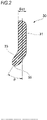
- Fig. 2 is a cross-sectional view of the seal member illustrated in Fig. 1 .
- the seal member 30 has a circular ring-shaped base portion 31 extending in the radial direction and an inclined portion 33 integrally formed inside the base portion 31 in the radial direction and inclined toward one axial end side with respect to the base portion 31.
- An inclination angle ⁇ of the inclined portion 33 with respect to the base portion 31 of the seal member 30, that is, the angle formed by the radial direction of the base portion 31 and an extension direction of the inclined portion 33 is 10° to 80°.
- the inclination angle ⁇ that is smaller than the above range results in an excessive contact resistance. In a case where the inclination angle ⁇ is larger than the above range, the flow resistance of the compressed air becomes excessive.
- the inclination angle ⁇ is preferably 20° to 60° and more preferably 25° to 50°.
- the base portion 31 is inserted into the groove portion 13 together with the retaining ring 40 and fixed to the groove portion 13.
- the groove portion 13 has a tapered surface 15 that is inclined to the outside in the radial direction, increases in diameter toward the inside in the axial direction and is in contact with the retaining ring 40 and an axial inside surface 17 that is in contact with an axial side surface of the base portion 31 inside the tapered surface 15 in the axial direction.
- the outer diameter side end portion of the retaining ring 40 is in line contact with the tapered surface 15 along the circumferential direction.
- the retaining ring 40 is made of the elastic member urged outward in the radial direction, and thus a force is generated to press the seal member 30 to the inside in the axial direction.
- the retaining ring 40 may have a circular cross section in addition to a rectangular cross section.
- the retaining ring 40 may be provided with an inclined surface, the groove portion 13 may have a rectangular cross section, and a corner portion of the groove portion 13 having the rectangular cross section may be pressed against the inclined surface of the retaining ring 40.
- the inclined portion 33 is inclined to the downstream side in the compressed air supply direction (outside in the axial direction) toward the inside in the radial direction and is capable of being in contact with the inclined surface 23 of the inner ring 20.
- An inner peripheral surface 35 of the inclined portion 33 has a circular ring shape (conical surface shape).
- the inclined surface 23 of the inner ring 20 with which the inclined portion 33 is capable of being in contact also has a circular ring shape (conical surface shape). Accordingly, the inner peripheral surface 35 of the inclined portion 33 is capable of being in contact with the inclined surface of the inner ring 20 over an entire circumference.
- the seal member 30 is capable of sealing the bearing internal space S between the inner peripheral surface 11 of the outer ring 10 and the outer peripheral surface 21 of the inner ring 20 over the entire circumference.
- the supplied compressed air flows into the bearing internal space S and the pressure of the compressed air acts on the seal member 30.
- the inclined portion 33 is elastically deformed toward the downstream side of the flow of the compressed air.
- a contact area between the inner peripheral surface 35 of the inclined portion 33 and the inclined surface 23 of the inner ring 20 becomes smaller than in a case where the pressure of the compressed air does not act.
- the state of the inclined portion 33 becomes an open state where compressed air communication is allowed.
- the seal member 30 does not have a core metal and is made of only an elastic material, the seal member 30 has a structure that is elastically deformed with ease as a whole.
- the inclined portion 33 does not interfere with the retaining ring 40 at all, and thus the seal member 30 is supported by the outer ring 10 so as to be elastically deformed with ease. Accordingly, when the compressed air acts on the seal member 30 beyond a specific pressure, the inner peripheral portion of the seal member 30 is elastically deformed toward the outside in the axial direction and the contact area between the inner peripheral surface 35 of the inclined portion 33 and the inclined surface 23 of the inner ring 20 decreases.
- the inclined portion 33 of the seal member 30 is elastically deformed with reliability and the contact area can be reduced even in a case where the supply pressure of the compressed air is relatively small.
- an air turbine can be started smoothly, the frictional resistance between the seal member 30 and the inner ring 20 can be reduced, and a rotary shaft 101 can be rotated at an ultra-high speed rotation of approximately 400,000 min -1 .
- the inclined surface 23 is provided on the end portion of the outer peripheral surface 21 of the inner ring 20 on the downstream side in the compressed air supply direction, the flow of the compressed air passing between the inclined portion 33 and the inclined surface 23 is smooth and the ultra-high speed rotation even faster than that of the related art can be realized.
- the seal member 30 is formed such that the following expression (1) is satisfied when Skn is a radial length from an inclination start part P of the inclined portion 33 on the inside in the axial direction to an outermost diameter position of a part of contact of the seal member 30 with the outer peripheral surface 21 of the inner ring 20 and Skt is a thickness of the inclined portion 33 in a direction perpendicular to an inclination direction. 0.25 ⁇ Skn / Skt ⁇ 2.5
- Skn / Skt being 0.25 or more, the length of the inclined portion 33 that receives the compressed air can be ensured, the seal member 30 can be brought into contact with the outer peripheral surface 21 of the inner ring 20 at an appropriate angle, the inclined portion 33 is also deformed with ease, and thus the seal member 30 is easy to come out of contact with the outer peripheral surface 21 of the inner ring 20 even with a small compressed air amount.
- Skn / Skt is preferably 0.65 or more and more preferably 0.90 or more for the seal member 30 to come out of contact with the outer peripheral surface 21 of the inner ring 20 with greater ease.
- Skn / Skt may be 2.5 or less, is preferably 2.1 or less, and is more preferably 1.75 or less.
- the outermost diameter position of the part of contact of the seal member 30 with the outer peripheral surface 21 of the inner ring 20 is the boundary part between the inclined surface 23 and the cylindrical surface on the outer peripheral surface 21 of the inner ring 20.
- the outermost diameter position may be an intermediate part of the inclined surface 23.
- the seal member 30 is formed such that the ratio of the radial length Skn to Scn satisfies the following expression (2) when Scn is a radial length between an inclination start part R of the inclined portion 33 on the inside in the axial direction and an inner diameter of the retaining ring 40 at a time when the seal member 30 and the retaining ring 40 are attached to the groove portion 13 of the outer ring 10. 0.21 ⁇ Skn / Scn ⁇ 4.7
- Skn / Scn being 0.21 or more, the length of the inclined portion 33 that receives the compressed air can be ensured between the inner diameter of the retaining ring 40 and the outer peripheral surface 21 of the inner ring 20, the seal member 30 can be brought into contact with the outer peripheral surface 21 of the inner ring 20 at an appropriate angle, and thus the seal member 30 is easy to come out of contact with the outer peripheral surface 21 of the inner ring 20 even with a small compressed air amount.
- Skn / Scn is preferably 0.42 or more for the seal member 30 to easily come out of contact with the outer peripheral surface 21 of the inner ring 20.
- Skn / Scn may be 4.7 or less and is preferably 1.6 or less.
- the ratio of the radial length Skn to Ngn satisfies the following expression (3) when Ngn is a radial length between the outermost diameter position of the part of contact of the seal member 30 with the outer peripheral surface 21 of the inner ring 20 and an axial center X of the rolling bearing 1. 0.025 ⁇ Skn / Ngn ⁇ 0.25
- the length of the inclined portion 33 that receives the compressed air can be ensured even in a case of a rolling bearing that has a predetermined dimension and the seal member 30 can be brought into contact with the outer peripheral surface 21 of the inner ring 20 at an appropriate angle. Accordingly, the seal member 30 is easy to come out of contact with the outer peripheral surface 21 of the inner ring 20 even with a small compressed air amount.
- 0.065 ⁇ Skn / Ngn ⁇ 0.21 is preferable and 0.090 ⁇ Skn / Ngn ⁇ 0.18 is more preferable for the seal member 30 to easily come out of contact with the outer peripheral surface 21 of the inner ring 20.
- the seal member 30 is formed such that the following expression (4) is satisfied when Sks is a radial length from an inclination start part Q of the inclined portion 33 on the outside in the axial direction to the outermost diameter position of the part of contact of the seal member 30 with the outer peripheral surface 21 of the inner ring 20 and Sct is a thickness in the axial direction at the inclination start part Q of the inclined portion 33 on the outside in the axial direction.
- Sks is a radial length from an inclination start part Q of the inclined portion 33 on the outside in the axial direction to the outermost diameter position of the part of contact of the seal member 30 with the outer peripheral surface 21 of the inner ring 20
- Sct is a thickness in the axial direction at the inclination start part Q of the inclined portion 33 on the outside in the axial direction.
- Sks / Sct being 0.5 or more, the length of the inclined portion 33 for receiving the compressed air and opening to the outside of the bearing can be ensured and the seal member 30 can be brought into contact with the outer peripheral surface 21 of the inner ring 20 at an appropriate angle. Accordingly, the seal member 30 is easy to come out of contact with the outer peripheral surface 21 of the inner ring 20 even with a small compressed air amount.
- Sks / Sct is preferably 0.75 or more and more preferably 1 or more for the seal member 30 to come out of contact with the outer peripheral surface 21 of the inner ring 20 with greater ease.
- Sks / Sct may be 3 or less, is preferably 2.5 or less, and is more preferably 2 or less.
- the seal member 30 is formed such that the ratio of the radial length Sks to Scs satisfies the following expression (5) when Scs is a radial length between the inclination start part Q of the inclined portion 33 on the outside in the axial direction and the inner diameter of the retaining ring 40 at a time when the seal member 30 and the retaining ring 40 are attached to the groove portion 13 of the outer ring 10. 0.35 ⁇ Sks / Scs ⁇ 3.75
- Sks / Scs being 0.35 or more, the length of the inclined portion 33 that receives the compressed air can be ensured between the inner diameter of the retaining ring 40 and the outer peripheral surface 21 of the inner ring 20, the seal member 30 can be brought into contact with the outer peripheral surface 21 of the inner ring 20 at an appropriate angle, and thus the seal member 30 is easy to come out of contact with the outer peripheral surface 21 of the inner ring 20 even with a small compressed air amount.
- Sks / Scs is preferably 0.62 or more for the seal member 30 to come out of contact with the outer peripheral surface 21 of the inner ring 20 with greater ease.
- Sks / Scs may be 3.75 or less and is preferably 2.0 or less.
- the ratio of the radial length Sks to Ngn satisfies the following expression (6) when Ngn is a radial length between the outermost diameter position of the part of contact of the seal member 30 with the outer peripheral surface 21 of the inner ring 20 and the axial center X of the rolling bearing 1.
- Ngn is a radial length between the outermost diameter position of the part of contact of the seal member 30 with the outer peripheral surface 21 of the inner ring 20 and the axial center X of the rolling bearing 1.
- the length of the inclined portion 33 that receives the compressed air can be ensured even in the case of a rolling bearing that has a predetermined dimension and the seal member 30 can be brought into contact with the outer peripheral surface 21 of the inner ring 20 at an appropriate angle. Accordingly, the seal member 30 is easy to come out of contact with the outer peripheral surface 21 of the inner ring 20 even with a small compressed air amount. 0.10 ⁇ Sks / Ngn ⁇ 0.23 is preferable for the seal member 30 to easily come out of contact with the outer peripheral surface 21 of the inner ring 20.
- the ratio of Ts to Sct satisfies the following expression (7) when Ts is a circumferential gap of the retaining ring 40 at a time when the seal member 30 and the retaining ring 40 are attached to the groove portion 13 of the outer ring 10 and Sct is an axial thickness of the part of the seal member 30 in contact with the retaining ring 40 (that is, the axial thickness at the inclination start part Q of the inclined portion 33 on the outside in the axial direction).
- Ts / Sct being 10 or less, it is possible to prevent the seal member 30 from floating from the circumferential gap Ts of the retaining ring 40 and prevent the seal member 30 from coming off from the groove portion 13 of the outer ring 10 when the compressed air is supplied. Accordingly, Ts / Sct is preferably 6 or less and more preferably 5 or less.
- Ts / Sct When Ts / Sct is less than 1, both circumferential end portions are in contact with each other when the retaining ring 40 is reduced in diameter and the retaining ring 40 cannot be sufficiently reduced in diameter. Accordingly, Ts / Sct may be 1 or more, is preferably 2 or more, and is more preferably 2.5 or more.
- the pressure of the compressed air acting on the inclined portion 33 decreases when the supply of compressed air to the turbine blade 103 is stopped by stopping driving a dental air turbine handpiece 200. Then, the inclined portion 33 returns to the state illustrated in Fig. 1 and the inner peripheral surface 35 of the inclined portion 33 comes into contact with the inclined surface 23 of the inner ring 20 over the entire circumference. In other words, the inclined portion 33 is closed and functions as a brake for the inner ring 20. In this case, the inner peripheral surface 35 of the inclined portion 33 comes into contact with the inclined surface 23 of the inner ring 20 over the entire circumference, and thus the maximum brake effect attributable to the frictional resistance between the seal member 30 and the inner ring 20 can be obtained. As a result, it is possible to stop the rotary shaft 101 fixed to the inner ring 20 most quickly.
- the inclined portion 33 of the seal member 30, which is particularly easy to be elastically deformed, is configured to be in contact with the inclined surface 23 of the inner ring 20, the contact pressure between the seal member 30 and the inclined surface 23 can be reduced as compared with the case of contact in the radial direction.
- the compressed air-based opening-closing operation of the seal member 30 can be performed smoothly and with high responsiveness.
- the contact pressure can be reduced with a compressed air pressure smaller than in the structure of the related art and the rotation speed of the rotary shaft 101 can be further improved and the stop time can be shortened at the same time.
- the contact surface of the inclined portion 33 may be a surface coming into line contact with the inclined surface 23 of the inner ring 20. In that case, the frictional resistance is reduced as compared with the case of area contact, which is advantageous for high-speed rotation.
- the seal member 30 is disposed in one axial end portion on the side opposite to the compressed air inlet of the outer ring 10 although the rotary shaft 101 is provided with a pair of rolling bearings as illustrated in Fig. 4 .
- a pair of rolling bearings as illustrated in Fig. 4 .
- lubricating oil can be supplied into each rolling bearing from a bearing end portion side where the seal member 30 is not disposed.
- the seal member 30 is disposed on a side opposite to a spray lubrication side, liquid leakage does not occur from each rolling bearing to the outside of the head portion 122.
- Dental air turbine handpieces are usually autoclaved for high-temperature cleaning and sterilization after use.
- the amount of lubricating oil in the rolling bearing decreases as a result of this treatment, the seal member 30 is disposed only in one axial end portion of the rolling bearing, and thus the lubricating oil can be easily supplied from the other end portion in the axial direction. Accordingly, the lubrication state of the rolling bearing can always be satisfactory and the rotary shaft 101 can be stably driven to rotate.
- the present invention is not limited to each of the above embodiments and can be modified and improved as appropriate.
- the present invention is not limited thereto and the rim portion 7 may be disposed on the seal member side on the opposite side in the axial direction.
- the seal member is disposed only on one axial end side of the rolling bearing 1 and thus the groove portion 13 of the outer ring 10 and the inclined surface 23 of the inner ring 20 are formed only on one axial end side
- the present invention is not limited thereto and the groove portion 13 and the inclined surface 23 may be symmetrically formed on the other axial end side as well. In that case, one of the pair of inclined surfaces is not used, and yet it is not necessary to be aware of the direction of assembly in the process of rolling bearing assembly and the work process can be simplified.
- a wall thickness of the inclined portion may be a constant thickness or may gradually decrease toward the inside in the radial direction.
- the thickness Skt of the inclined portion 33 in the direction perpendicular to the inclination direction is a thickness of the thickest part.
Landscapes
- Engineering & Computer Science (AREA)
- General Engineering & Computer Science (AREA)
- Mechanical Engineering (AREA)
- Rolling Contact Bearings (AREA)
Abstract
Description
- The present invention relates to a rolling bearing for an air turbine.
- Small and lightweight air turbine handpieces are often used in dental treatment. A dental
air turbine handpiece 120 as an example is illustrated inFig. 4 . The dentalair turbine handpiece 120 includes agrip portion 121 and ahead portion 122 provided in the tip portion of thegrip portion 121. A surgeon holds thegrip portion 121 and performs, for example, tooth cutting. - As illustrated in
Fig. 5 , in this type ofair turbine handpiece 120, arotary shaft 101 having aturbine blade 103 receiving compressed air from an air supply port is rotatably stored in a housing 105 having the air supply port and an air discharge port. Therotary shaft 101 is supported by the housing 105 so as to be rotatable at a high speed via a pair ofrolling bearings 130. Tooth cutting or the like is performed by a surgeon operating theair turbine handpiece 120 while rotating a therapeutic tool attached to therotary shaft 101 at a high speed. - The
rolling bearings 130 are supported by the housing 105 viarubber rings 113 mounted inannular recesses rolling bearings 130 is urged to the other rolling bearing 130 side by aspring washer 115. - In the rolling
bearing 130 described inPatent Literature 1, aseal member 132 is fixed by aretaining ring 133 to the groove portion formed on the inner peripheral surface of anouter ring 131, has an inclined portion inclined to the outside in an axial direction as an inner peripheral portion is directed toward an inner diameter side, and can be elastically deformed in the axial direction or a radial direction of a bearing. The inner peripheral portion of theseal member 132 comes into or out of contact with the outer peripheral surface of aninner ring 134 depending on the presence and absence of compressed air. As a result, it is possible to achieve both ultra-high speed rotation and quick stop with this configuration. - Patent Literature 1:
JP-A-2017-211076 - In the rolling bearing for an air turbine handpiece, the seal member is required to come out of contact with the outer peripheral surface of the inner ring, even with a small compressed air amount, when compressed air is supplied. Further improvement is required in this regard.
- The present invention has been made in view of the above circumstances, and an object of the present invention is to provide a rolling bearing for an air turbine in which a seal member is capable of coming out of contact with an outer peripheral surface of an inner ring, even with a small compressed air amount, when compressed air is supplied.
- The above object of the present invention is achieved by the following configuration.
- (1) A rolling bearing for an air turbine including:
- an outer ring;
- an inner ring;
- a plurality of rolling bodies rollably disposed between the outer ring and the inner ring; and
- a substantially annular seal member provided in one axial end portion of a bearing internal space between the outer ring and the inner ring and made of an elastic body without a core metal, in which
- an outer peripheral portion of the seal member is fixed by a retaining ring to a groove portion formed on an inner peripheral surface of the outer ring in the one axial end portion and an inner peripheral portion of the seal member is elastically deformable,
- the one axial end portion is on a side opposite to an inlet of compressed air supplied to the bearing internal space,
- the seal member includes an inclined portion inclined toward one axial end portion side on an inner diameter side, and
- the seal member satisfies 0.25 ≤ Skn / Skt ≤ 2.5 when Skn is a radial length from an inclination start part of the inclined portion on an inside in an axial direction to an outermost diameter position of a part of contact of the seal member with an outer peripheral surface of the inner ring and Skt is a thickness of the inclined portion in a direction perpendicular to an inclination direction.
- (2) The rolling bearing for an air turbine according to (1), in which 0.21 ≤ Skn / Scn ≤ 4.7 is satisfied when Scn is a radial length between the inclination start part of the inclined portion on the inside in the axial direction and an inner diameter of the retaining ring at a time when the seal member and the retaining ring are attached to the groove portion of the outer ring.
- (3) The rolling bearing for an air turbine according to (1) or (2), in which 0.05 ≤ Sks / Ngn ≤ 0.31 is satisfied when Sks is a radial length from an inclination start part of the inclined portion on an outside in the axial direction to the outermost diameter position of the part of contact of the seal member with the outer peripheral surface of the inner ring and Ngn is a radial length between the outermost diameter position of the part of contact of the seal member with the outer peripheral surface of the inner ring and an axial center of the rolling bearing.
- With the rolling bearing for an air turbine of the present invention, a seal member is capable of coming out of contact with the outer peripheral surface of an inner ring, even with a small compressed air amount, when compressed air is supplied.
-
-
Fig. 1 is a partial cross-sectional view illustrating a state where a rolling bearing of one embodiment of the present invention is stopped. -
Fig. 2 is a cross-sectional view of a seal member illustrated inFig. 1 . -
Fig. 3 is a cross-sectional view taken along line III-III ofFig. 1 , illustrating a retaining ring inserted in an outer ring over an entire circumference. -
Fig. 4 is a schematic side view of a dental air turbine handpiece. -
Fig. 5 is a cross-sectional view of a main part of the dental air turbine handpiece illustrated inFig. 4 . - Hereinafter, embodiments of a rolling bearing for an air turbine according to the present invention will be described in detail with reference to the drawings.
-
Fig. 1 is a partial cross-sectional view illustrating a state where a rolling bearing of a first embodiment is stopped. - A rolling
bearing 1 is a ball bearing including anouter ring 10 having an outerring raceway surface 10a, aninner ring 20 having an innerring raceway surface 20a, a plurality of balls (rolling bodies) 3 rollably disposed between theouter ring 10 and theinner ring 20, and acage 5 rollably holding the plurality ofballs 3. The present invention is not limited to the ball bearing in the illustrated example and may be an angular-type ball bearing. - The
cage 5 is a so-called crown-type cage. As for thecage 5, a substantially circular ring-shaped rim portion 7 is positioned on an upstream side from theball 3 in a compressed air supply direction, that is, on the right side inFig. 1 . The arrow P in the drawing indicates the direction in which the compressed air flows. - A circular ring-
shaped seal member 30 is provided between theouter ring 10 and theinner ring 20. Theseal member 30 is made of an elastic body configured from only an elastic material without a core metal. The outer peripheral portion of theseal member 30 is fixed by aretaining ring 40 to agroove portion 13 formed on the inner peripheral surface of theouter ring 10, and the inner peripheral portion can be elastically deformed in an axial direction and a radial direction of a bearing. - A water-resistant acrylic rubber with a Shore A hardness (JIS K 6253) of 60 to 90, a general water-resistant fluororubber with a Shore A hardness of 60 to 90, or the like can be used as an elastic member by which the
seal member 30 is configured. By using the above material for theseal member 30, appropriate elastic properties can be obtained and durability and wear resistance are also improved. - The
seal member 30 is provided on a downstream side from theball 3 in the compressed air supply direction, that is, on the left side inFig. 1 . In other words, theseal member 30 is provided in one axial end portion on the side of a bearing internal space S opposite to a compressed air supply side (compressed air inlet). Thegroove portion 13 fixing theseal member 30 is formed on an innerperipheral surface 11 of theouter ring 10. Theseal member 30 is fixed to thegroove portion 13 by theretaining ring 40. The shape of theseal member 30 is not limited to the circular ring shape. Theseal member 30 may have another shape insofar as the shape is substantially annular as described later. - An outer
peripheral surface 21 of theinner ring 20 has aninclined surface 23 in the end portion on the downstream side in the compressed air supply direction, that is, on the left side inFig. 1 . Theinclined surface 23 may be cylindrical although it is preferable that theinclined surface 23 is formed in a circular ring shape (conical surface shape) inclined from a large diameter to a small diameter toward the axial end on the seal member side in the axial direction. -
Fig. 2 is a cross-sectional view of the seal member illustrated inFig. 1 . - The
seal member 30 has a circular ring-shaped base portion 31 extending in the radial direction and aninclined portion 33 integrally formed inside thebase portion 31 in the radial direction and inclined toward one axial end side with respect to thebase portion 31. An inclination angle θ of theinclined portion 33 with respect to thebase portion 31 of theseal member 30, that is, the angle formed by the radial direction of thebase portion 31 and an extension direction of theinclined portion 33 is 10° to 80°. The inclination angle θ that is smaller than the above range results in an excessive contact resistance. In a case where the inclination angle θ is larger than the above range, the flow resistance of the compressed air becomes excessive. The inclination angle θ is preferably 20° to 60° and more preferably 25° to 50°. - As illustrated in
Fig. 1 , thebase portion 31 is inserted into thegroove portion 13 together with the retainingring 40 and fixed to thegroove portion 13. Thegroove portion 13 has a taperedsurface 15 that is inclined to the outside in the radial direction, increases in diameter toward the inside in the axial direction and is in contact with the retainingring 40 and an axialinside surface 17 that is in contact with an axial side surface of thebase portion 31 inside the taperedsurface 15 in the axial direction. The outer diameter side end portion of the retainingring 40 is in line contact with the taperedsurface 15 along the circumferential direction. The retainingring 40 is made of the elastic member urged outward in the radial direction, and thus a force is generated to press theseal member 30 to the inside in the axial direction. As a result, thebase portion 31 is strongly sandwiched between the retainingring 40 and the axial insidesurface 17 and theseal member 30 is firmly fixed to theouter ring 10. The retainingring 40 may have a circular cross section in addition to a rectangular cross section. In addition, the retainingring 40 may be provided with an inclined surface, thegroove portion 13 may have a rectangular cross section, and a corner portion of thegroove portion 13 having the rectangular cross section may be pressed against the inclined surface of the retainingring 40. - The
inclined portion 33 is inclined to the downstream side in the compressed air supply direction (outside in the axial direction) toward the inside in the radial direction and is capable of being in contact with theinclined surface 23 of theinner ring 20. An innerperipheral surface 35 of theinclined portion 33 has a circular ring shape (conical surface shape). Theinclined surface 23 of theinner ring 20 with which theinclined portion 33 is capable of being in contact also has a circular ring shape (conical surface shape). Accordingly, the innerperipheral surface 35 of theinclined portion 33 is capable of being in contact with the inclined surface of theinner ring 20 over an entire circumference. In other words, theseal member 30 is capable of sealing the bearing internal space S between the innerperipheral surface 11 of theouter ring 10 and the outerperipheral surface 21 of theinner ring 20 over the entire circumference. - As illustrated in
Fig. 1 , the supplied compressed air flows into the bearing internal space S and the pressure of the compressed air acts on theseal member 30. Then, theinclined portion 33 is elastically deformed toward the downstream side of the flow of the compressed air. As a result, a contact area between the innerperipheral surface 35 of theinclined portion 33 and theinclined surface 23 of theinner ring 20 becomes smaller than in a case where the pressure of the compressed air does not act. In other words, the state of theinclined portion 33 becomes an open state where compressed air communication is allowed. - Since the
seal member 30 does not have a core metal and is made of only an elastic material, theseal member 30 has a structure that is elastically deformed with ease as a whole. In particular, theinclined portion 33 does not interfere with the retainingring 40 at all, and thus theseal member 30 is supported by theouter ring 10 so as to be elastically deformed with ease. Accordingly, when the compressed air acts on theseal member 30 beyond a specific pressure, the inner peripheral portion of theseal member 30 is elastically deformed toward the outside in the axial direction and the contact area between the innerperipheral surface 35 of theinclined portion 33 and theinclined surface 23 of theinner ring 20 decreases. - As described above, in this configuration, the
inclined portion 33 of theseal member 30 is elastically deformed with reliability and the contact area can be reduced even in a case where the supply pressure of the compressed air is relatively small. - As a result, an air turbine can be started smoothly, the frictional resistance between the
seal member 30 and theinner ring 20 can be reduced, and arotary shaft 101 can be rotated at an ultra-high speed rotation of approximately 400,000 min-1. Further, since theinclined surface 23 is provided on the end portion of the outerperipheral surface 21 of theinner ring 20 on the downstream side in the compressed air supply direction, the flow of the compressed air passing between theinclined portion 33 and theinclined surface 23 is smooth and the ultra-high speed rotation even faster than that of the related art can be realized. - As illustrated in
Fig. 1 , theseal member 30 is formed such that the following expression (1) is satisfied when Skn is a radial length from an inclination start part P of theinclined portion 33 on the inside in the axial direction to an outermost diameter position of a part of contact of theseal member 30 with the outerperipheral surface 21 of theinner ring 20 and Skt is a thickness of theinclined portion 33 in a direction perpendicular to an inclination direction.
- By Skn / Skt being 0.25 or more, the length of the
inclined portion 33 that receives the compressed air can be ensured, theseal member 30 can be brought into contact with the outerperipheral surface 21 of theinner ring 20 at an appropriate angle, theinclined portion 33 is also deformed with ease, and thus theseal member 30 is easy to come out of contact with the outerperipheral surface 21 of theinner ring 20 even with a small compressed air amount. Skn / Skt is preferably 0.65 or more and more preferably 0.90 or more for theseal member 30 to come out of contact with the outerperipheral surface 21 of theinner ring 20 with greater ease. - In a case where Skn / Skt is larger than 2.5, the length of the
inclined portion 33 is too long and a force of pressing against the outerperipheral surface 21 of theinner ring 20 is large or it is difficult to make contact at an appropriate angle. As a result, it is difficult for theseal member 30 to come out of contact with the outerperipheral surface 21 of theinner ring 20 with a small compressed air amount. Accordingly, Skn / Skt may be 2.5 or less, is preferably 2.1 or less, and is more preferably 1.75 or less. - In the present embodiment, the outermost diameter position of the part of contact of the
seal member 30 with the outerperipheral surface 21 of theinner ring 20 is the boundary part between theinclined surface 23 and the cylindrical surface on the outerperipheral surface 21 of theinner ring 20. Alternatively, the outermost diameter position may be an intermediate part of theinclined surface 23. - The
seal member 30 is formed such that the ratio of the radial length Skn to Scn satisfies the following expression (2) when Scn is a radial length between an inclination start part R of theinclined portion 33 on the inside in the axial direction and an inner diameter of the retainingring 40 at a time when theseal member 30 and the retainingring 40 are attached to thegroove portion 13 of theouter ring 10.
- By Skn / Scn being 0.21 or more, the length of the
inclined portion 33 that receives the compressed air can be ensured between the inner diameter of the retainingring 40 and the outerperipheral surface 21 of theinner ring 20, theseal member 30 can be brought into contact with the outerperipheral surface 21 of theinner ring 20 at an appropriate angle, and thus theseal member 30 is easy to come out of contact with the outerperipheral surface 21 of theinner ring 20 even with a small compressed air amount. Skn / Scn is preferably 0.42 or more for theseal member 30 to easily come out of contact with the outerperipheral surface 21 of theinner ring 20. - In a case where Skn / Scn is larger than 4.7, the length of the
inclined portion 33 is too long and theseal member 30 cannot be brought into contact with the outerperipheral surface 21 of theinner ring 20 at an appropriate angle. As a result, it is difficult for theseal member 30 to come out of contact with the outerperipheral surface 21 of theinner ring 20 with a small compressed air amount. Accordingly, Skn / Scn may be 4.7 or less and is preferably 1.6 or less. - The ratio of the radial length Skn to Ngn satisfies the following expression (3) when Ngn is a radial length between the outermost diameter position of the part of contact of the
seal member 30 with the outerperipheral surface 21 of theinner ring 20 and an axial center X of the rollingbearing 1.
- By satisfying the expression (3), the length of the
inclined portion 33 that receives the compressed air can be ensured even in a case of a rolling bearing that has a predetermined dimension and theseal member 30 can be brought into contact with the outerperipheral surface 21 of theinner ring 20 at an appropriate angle. Accordingly, theseal member 30 is easy to come out of contact with the outerperipheral surface 21 of theinner ring 20 even with a small compressed air amount. 0.065 ≤ Skn / Ngn ≤ 0.21 is preferable and 0.090 ≤ Skn / Ngn ≤ 0.18 is more preferable for theseal member 30 to easily come out of contact with the outerperipheral surface 21 of theinner ring 20. - As illustrated in
Fig. 1 , theseal member 30 is formed such that the following expression (4) is satisfied when Sks is a radial length from an inclination start part Q of theinclined portion 33 on the outside in the axial direction to the outermost diameter position of the part of contact of theseal member 30 with the outerperipheral surface 21 of theinner ring 20 and Sct is a thickness in the axial direction at the inclination start part Q of theinclined portion 33 on the outside in the axial direction.
- By Sks / Sct being 0.5 or more, the length of the
inclined portion 33 for receiving the compressed air and opening to the outside of the bearing can be ensured and theseal member 30 can be brought into contact with the outerperipheral surface 21 of theinner ring 20 at an appropriate angle. Accordingly, theseal member 30 is easy to come out of contact with the outerperipheral surface 21 of theinner ring 20 even with a small compressed air amount. Sks / Sct is preferably 0.75 or more and more preferably 1 or more for theseal member 30 to come out of contact with the outerperipheral surface 21 of theinner ring 20 with greater ease. - In a case where Sks / Sct is larger than 3, the length of the
inclined portion 33 is too long and the force of pressing against the outerperipheral surface 21 of theinner ring 20 is large or it is difficult to make contact at an appropriate angle. As a result, it is difficult for theseal member 30 to come out of contact with the outerperipheral surface 21 of theinner ring 20 with a small compressed air amount. Accordingly, Sks / Sct may be 3 or less, is preferably 2.5 or less, and is more preferably 2 or less. - The
seal member 30 is formed such that the ratio of the radial length Sks to Scs satisfies the following expression (5) when Scs is a radial length between the inclination start part Q of theinclined portion 33 on the outside in the axial direction and the inner diameter of the retainingring 40 at a time when theseal member 30 and the retainingring 40 are attached to thegroove portion 13 of theouter ring 10.
- By Sks / Scs being 0.35 or more, the length of the
inclined portion 33 that receives the compressed air can be ensured between the inner diameter of the retainingring 40 and the outerperipheral surface 21 of theinner ring 20, theseal member 30 can be brought into contact with the outerperipheral surface 21 of theinner ring 20 at an appropriate angle, and thus theseal member 30 is easy to come out of contact with the outerperipheral surface 21 of theinner ring 20 even with a small compressed air amount. Sks / Scs is preferably 0.62 or more for theseal member 30 to come out of contact with the outerperipheral surface 21 of theinner ring 20 with greater ease. - In a case where Sks / Scs is larger than 3.75, the length of the
inclined portion 33 is too long and theseal member 30 cannot be brought into contact with the outerperipheral surface 21 of theinner ring 20 at an appropriate angle. As a result, it is difficult for theseal member 30 to come out of contact with the outerperipheral surface 21 of theinner ring 20 with a small compressed air amount. Accordingly, Sks / Scs may be 3.75 or less and is preferably 2.0 or less. - The ratio of the radial length Sks to Ngn satisfies the following expression (6) when Ngn is a radial length between the outermost diameter position of the part of contact of the
seal member 30 with the outerperipheral surface 21 of theinner ring 20 and the axial center X of the rollingbearing 1.
- By satisfying the expression (6), the length of the
inclined portion 33 that receives the compressed air can be ensured even in the case of a rolling bearing that has a predetermined dimension and theseal member 30 can be brought into contact with the outerperipheral surface 21 of theinner ring 20 at an appropriate angle. Accordingly, theseal member 30 is easy to come out of contact with the outerperipheral surface 21 of theinner ring 20 even with a small compressed air amount. 0.10 ≤ Sks / Ngn ≤ 0.23 is preferable for theseal member 30 to easily come out of contact with the outerperipheral surface 21 of theinner ring 20. - As illustrated in
Figs. 1 to 3 , the ratio of Ts to Sct satisfies the following expression (7) when Ts is a circumferential gap of the retainingring 40 at a time when theseal member 30 and the retainingring 40 are attached to thegroove portion 13 of theouter ring 10 and Sct is an axial thickness of the part of theseal member 30 in contact with the retaining ring 40 (that is, the axial thickness at the inclination start part Q of theinclined portion 33 on the outside in the axial direction).
- By Ts / Sct being 10 or less, it is possible to prevent the
seal member 30 from floating from the circumferential gap Ts of the retainingring 40 and prevent theseal member 30 from coming off from thegroove portion 13 of theouter ring 10 when the compressed air is supplied. Accordingly, Ts / Sct is preferably 6 or less and more preferably 5 or less. - When Ts / Sct is less than 1, both circumferential end portions are in contact with each other when the retaining
ring 40 is reduced in diameter and the retainingring 40 cannot be sufficiently reduced in diameter. Accordingly, Ts / Sct may be 1 or more, is preferably 2 or more, and is more preferably 2.5 or more. - The pressure of the compressed air acting on the
inclined portion 33 decreases when the supply of compressed air to theturbine blade 103 is stopped by stopping driving a dental air turbine handpiece 200. Then, theinclined portion 33 returns to the state illustrated inFig. 1 and the innerperipheral surface 35 of theinclined portion 33 comes into contact with theinclined surface 23 of theinner ring 20 over the entire circumference. In other words, theinclined portion 33 is closed and functions as a brake for theinner ring 20. In this case, the innerperipheral surface 35 of theinclined portion 33 comes into contact with theinclined surface 23 of theinner ring 20 over the entire circumference, and thus the maximum brake effect attributable to the frictional resistance between theseal member 30 and theinner ring 20 can be obtained. As a result, it is possible to stop therotary shaft 101 fixed to theinner ring 20 most quickly. - In addition, since the
inclined portion 33 of theseal member 30, which is particularly easy to be elastically deformed, is configured to be in contact with theinclined surface 23 of theinner ring 20, the contact pressure between theseal member 30 and theinclined surface 23 can be reduced as compared with the case of contact in the radial direction. As a result, the compressed air-based opening-closing operation of theseal member 30 can be performed smoothly and with high responsiveness. In addition, the contact pressure can be reduced with a compressed air pressure smaller than in the structure of the related art and the rotation speed of therotary shaft 101 can be further improved and the stop time can be shortened at the same time. - By providing the
inclined portion 33 at the tip of theseal member 30 with a contact surface coming into area contact with theinclined surface 23 of theinner ring 20, the surface pressure that acts on theseal member 30 is reduced and wear is reduced. In addition, sealability is improved as a result of an increase in the contact area. - Further, the contact surface of the
inclined portion 33 may be a surface coming into line contact with theinclined surface 23 of theinner ring 20. In that case, the frictional resistance is reduced as compared with the case of area contact, which is advantageous for high-speed rotation. - In a dental air turbine handpiece in particular, extremely high-speed rotation is required in grinding a tooth and a rotation stop performance as sudden as within 2 seconds, preferably within 1 second, is required in stopping. According to this configuration, the above effects of rotation speed increase and stop time shortening can be stably obtained, and thus the usability of the dental air turbine handpiece can be improved considerably.
- When the dental air turbine handpiece is driven, compressed air is less likely to leak out of the bearing as compared with a seal member-less case, and thus drive noise is reduced and high quietness can be obtained.
- The
seal member 30 is disposed in one axial end portion on the side opposite to the compressed air inlet of theouter ring 10 although therotary shaft 101 is provided with a pair of rolling bearings as illustrated inFig. 4 . As a result, by spray lubrication from between the pair of rolling bearings, lubricating oil can be supplied into each rolling bearing from a bearing end portion side where theseal member 30 is not disposed. In addition, since theseal member 30 is disposed on a side opposite to a spray lubrication side, liquid leakage does not occur from each rolling bearing to the outside of thehead portion 122. - Dental air turbine handpieces are usually autoclaved for high-temperature cleaning and sterilization after use. Although the amount of lubricating oil in the rolling bearing decreases as a result of this treatment, the
seal member 30 is disposed only in one axial end portion of the rolling bearing, and thus the lubricating oil can be easily supplied from the other end portion in the axial direction. Accordingly, the lubrication state of the rolling bearing can always be satisfactory and therotary shaft 101 can be stably driven to rotate. - The present invention is not limited to each of the above embodiments and can be modified and improved as appropriate.
- For example, although the
rim portion 7 on one end side of thecage 5 used for the rollingbearing 1 of the above embodiments is disposed on the upstream side from theball 3 in the compressed air supply direction, the present invention is not limited thereto and therim portion 7 may be disposed on the seal member side on the opposite side in the axial direction. - Although the seal member is disposed only on one axial end side of the rolling
bearing 1 and thus thegroove portion 13 of theouter ring 10 and theinclined surface 23 of theinner ring 20 are formed only on one axial end side, the present invention is not limited thereto and thegroove portion 13 and theinclined surface 23 may be symmetrically formed on the other axial end side as well. In that case, one of the pair of inclined surfaces is not used, and yet it is not necessary to be aware of the direction of assembly in the process of rolling bearing assembly and the work process can be simplified. - As for the seal member, a wall thickness of the inclined portion may be a constant thickness or may gradually decrease toward the inside in the radial direction. In the latter case, the thickness Skt of the
inclined portion 33 in the direction perpendicular to the inclination direction is a thickness of the thickest part. - This application is based on a Japanese patent application filed on December 27, 2019 (
Japanese Patent Application No. 2019-238706 Japanese Patent Application No. 2019-238707 -
- 1: rolling bearing
- 3: ball (rolling body)
- 5: cage
- 7: rim portion
- 10: outer ring
- 11: inner peripheral surface
- 13: groove portion
- 15: tapered surface
- 17: axial inside surface
- 20: inner ring
- 21: outer peripheral surface
- 23: inclined surface
- 30: seal member
- 31: base portion
- 33: inclined portion
- 35: inner peripheral surface
- 40: retaining ring
- 100: bearing unit for air turbine
- 120: dental air turbine handpiece
- 122: head portion
- S: bearing internal space
- Skn: radial length from inclination start part of inclined portion of seal member on inside in axial direction to outermost diameter position of part of contact of seal member with outer peripheral surface of inner ring
- Skt: thickness of inclined portion in direction perpendicular to inclination direction
- Scn: radial length between inclination start part of inclined portion on inside in axial direction and inner diameter of retaining ring at time when seal member and retaining ring are attached to groove portion of outer ring
- Sks: radial length from inclination start part of inclined portion on outside in axial direction to outermost diameter position of part of contact of seal member with outer peripheral surface of inner ring
- Ngn: radial length between outermost diameter position of part of contact of seal member with outer peripheral surface of inner ring and axial center of rolling bearing
Claims (3)
- A rolling bearing for an air turbine comprising:an outer ring;an inner ring;a plurality of rolling bodies rollably disposed between the outer ring and the inner ring; anda substantially annular seal member provided in one axial end portion of a bearing internal space between the outer ring and the inner ring and made of an elastic body without a core metal, whereinan outer peripheral portion of the seal member is fixed by a retaining ring to a groove portion formed on an inner peripheral surface of the outer ring in the one axial end portion and an inner peripheral portion of the seal member is elastically deformable,the one axial end portion is on a side opposite to an inlet of compressed air supplied to the bearing internal space,the seal member includes an inclined portion inclined toward one axial end portion side on an inner diameter side, andthe seal member satisfies 0.25 ≤ Skn / Skt ≤ 2.5 when Skn is a radial length from an inclination start part of the inclined portion on an inside in an axial direction to an outermost diameter position of a part of contact of the seal member with an outer peripheral surface of the inner ring and Skt is a thickness of the inclined portion in a direction perpendicular to an inclination direction.
- The rolling bearing for an air turbine according to Claim 1, wherein 0.21 ≤ Skn / Scn ≤ 4.7 is satisfied when Scn is a radial length between the inclination start part of the inclined portion on the inside in the axial direction and an inner diameter of the retaining ring at a time when the seal member and the retaining ring are attached to the groove portion of the outer ring.
- The rolling bearing for an air turbine according to Claim 1 or 2, wherein 0.05 ≤ Sks / Ngn ≤ 0.31 is satisfied when Sks is a radial length from an inclination start part of the inclined portion on an outside in the axial direction to the outermost diameter position of the part of contact of the seal member with the outer peripheral surface of the inner ring and Ngn is a radial length between the outermost diameter position of the part of contact of the seal member with the outer peripheral surface of the inner ring and an axial center of the rolling bearing.
Applications Claiming Priority (3)
| Application Number | Priority Date | Filing Date | Title |
|---|---|---|---|
| JP2019238707 | 2019-12-27 | ||
| JP2019238706 | 2019-12-27 | ||
| PCT/JP2020/049025 WO2021132687A1 (en) | 2019-12-27 | 2020-12-25 | Rolling bearing for air turbine |
Publications (3)
| Publication Number | Publication Date |
|---|---|
| EP4083453A1 true EP4083453A1 (en) | 2022-11-02 |
| EP4083453A4 EP4083453A4 (en) | 2023-01-18 |
| EP4083453B1 EP4083453B1 (en) | 2026-02-18 |
Family
ID=76574494
Family Applications (1)
| Application Number | Title | Priority Date | Filing Date |
|---|---|---|---|
| EP20905217.4A Active EP4083453B1 (en) | 2019-12-27 | 2020-12-25 | Rolling bearing for air turbine |
Country Status (5)
| Country | Link |
|---|---|
| US (1) | US11953057B2 (en) |
| EP (1) | EP4083453B1 (en) |
| JP (1) | JPWO2021132687A1 (en) |
| CN (1) | CN114867948B (en) |
| WO (1) | WO2021132687A1 (en) |
Families Citing this family (1)
| Publication number | Priority date | Publication date | Assignee | Title |
|---|---|---|---|---|
| CN114867948B (en) * | 2019-12-27 | 2024-09-17 | 日本精工株式会社 | Rolling bearings for air turbines |
Family Cites Families (10)
| Publication number | Priority date | Publication date | Assignee | Title |
|---|---|---|---|---|
| JP2011127702A (en) | 2009-12-18 | 2011-06-30 | Ntn Corp | Rolling bearing |
| JP6331754B2 (en) * | 2013-07-09 | 2018-05-30 | 日本精工株式会社 | Ball bearing with seal ring |
| JP6249411B2 (en) | 2014-09-29 | 2017-12-20 | 豊田合成株式会社 | Bus bar |
| EP3653896B1 (en) * | 2014-12-25 | 2021-10-13 | NSK Ltd. | Rolling bearing for a bearing unit for an air turbine |
| US11540902B2 (en) | 2016-03-07 | 2023-01-03 | Nsk Ltd. | Rolling bearing, bearing unit for air turbine, and air turbine handpiece for dental use |
| CN108713108A (en) * | 2016-03-07 | 2018-10-26 | 日本精工株式会社 | Bearing units for rolling bearings and air turbines and handpieces for dental air turbines |
| JP6651912B2 (en) * | 2016-03-07 | 2020-02-19 | 日本精工株式会社 | Rolling bearings and bearing units for air turbines |
| JP6686738B2 (en) * | 2016-05-19 | 2020-04-22 | 日本精工株式会社 | Rolling bearings and bearing units for air turbines |
| CN114867948B (en) * | 2019-12-27 | 2024-09-17 | 日本精工株式会社 | Rolling bearings for air turbines |
| EP4083454B1 (en) * | 2019-12-27 | 2024-08-14 | NSK Ltd. | Rolling bearing for air turbine |
-
2020
- 2020-12-25 CN CN202080090512.5A patent/CN114867948B/en active Active
- 2020-12-25 JP JP2021567742A patent/JPWO2021132687A1/ja active Pending
- 2020-12-25 US US17/788,959 patent/US11953057B2/en active Active
- 2020-12-25 WO PCT/JP2020/049025 patent/WO2021132687A1/en not_active Ceased
- 2020-12-25 EP EP20905217.4A patent/EP4083453B1/en active Active
Also Published As
| Publication number | Publication date |
|---|---|
| WO2021132687A1 (en) | 2021-07-01 |
| JPWO2021132687A1 (en) | 2021-07-01 |
| US11953057B2 (en) | 2024-04-09 |
| US20230038467A1 (en) | 2023-02-09 |
| EP4083453A4 (en) | 2023-01-18 |
| EP4083453B1 (en) | 2026-02-18 |
| CN114867948B (en) | 2024-09-17 |
| CN114867948A (en) | 2022-08-05 |
Similar Documents
| Publication | Publication Date | Title |
|---|---|---|
| CN111503161B (en) | Bearing units for rolling bearings and air turbines and handpieces for dental air turbines | |
| CN107110222B (en) | Bearing units for air turbines | |
| JP6686738B2 (en) | Rolling bearings and bearing units for air turbines | |
| US11540902B2 (en) | Rolling bearing, bearing unit for air turbine, and air turbine handpiece for dental use | |
| EP4083453B1 (en) | Rolling bearing for air turbine | |
| EP4083454B1 (en) | Rolling bearing for air turbine | |
| US11564772B2 (en) | Rolling bearing, bearing unit for air turbine, and air turbine handpiece for dental use | |
| EP4119808A1 (en) | Rolling bearing | |
| WO2025110216A1 (en) | Bearing | |
| CN114718956A (en) | Cage, rolling bearing, bearing unit, and rotating apparatus | |
| WO2022202924A1 (en) | Bearing structure for transmission | |
| JP2009228750A (en) | Rolling bearing with grease reservoir | |
| JP2023164018A (en) | athletic stickers | |
| JP2020186747A (en) | Sealing device | |
| JPS61211530A (en) | Bearing device for cross-shaft universal joint |
Legal Events
| Date | Code | Title | Description |
|---|---|---|---|
| STAA | Information on the status of an ep patent application or granted ep patent |
Free format text: STATUS: THE INTERNATIONAL PUBLICATION HAS BEEN MADE |
|
| PUAI | Public reference made under article 153(3) epc to a published international application that has entered the european phase |
Free format text: ORIGINAL CODE: 0009012 |
|
| STAA | Information on the status of an ep patent application or granted ep patent |
Free format text: STATUS: REQUEST FOR EXAMINATION WAS MADE |
|
| 17P | Request for examination filed |
Effective date: 20220627 |
|
| AK | Designated contracting states |
Kind code of ref document: A1 Designated state(s): AL AT BE BG CH CY CZ DE DK EE ES FI FR GB GR HR HU IE IS IT LI LT LU LV MC MK MT NL NO PL PT RO RS SE SI SK SM TR |
|
| REG | Reference to a national code |
Ref country code: DE Ref legal event code: R079 Ipc: F16C0033780000 Ref document number: 602020067297 Country of ref document: DE Free format text: PREVIOUS MAIN CLASS: F16C0019060000 |
|
| A4 | Supplementary search report drawn up and despatched |
Effective date: 20221219 |
|
| RIC1 | Information provided on ipc code assigned before grant |
Ipc: F16J 15/3228 20160101ALI20221213BHEP Ipc: F16J 15/3268 20160101ALI20221213BHEP Ipc: F16J 15/3204 20160101ALI20221213BHEP Ipc: F16C 19/16 20060101ALI20221213BHEP Ipc: F16C 19/06 20060101ALI20221213BHEP Ipc: F16C 33/78 20060101AFI20221213BHEP |
|
| DAV | Request for validation of the european patent (deleted) | ||
| DAX | Request for extension of the european patent (deleted) | ||
| STAA | Information on the status of an ep patent application or granted ep patent |
Free format text: STATUS: EXAMINATION IS IN PROGRESS |
|
| 17Q | First examination report despatched |
Effective date: 20240312 |
|
| RIC1 | Information provided on ipc code assigned before grant |
Ipc: F16C 33/78 20060101AFI20250729BHEP Ipc: F16C 19/06 20060101ALI20250729BHEP Ipc: F16C 19/16 20060101ALI20250729BHEP Ipc: F16J 15/3204 20160101ALI20250729BHEP Ipc: F16J 15/3268 20160101ALI20250729BHEP Ipc: F16J 15/3228 20160101ALI20250729BHEP Ipc: F16C 27/06 20060101ALI20250729BHEP Ipc: F16C 33/41 20060101ALI20250729BHEP Ipc: F16C 35/077 20060101ALI20250729BHEP |
|
| GRAP | Despatch of communication of intention to grant a patent |
Free format text: ORIGINAL CODE: EPIDOSNIGR1 |
|
| STAA | Information on the status of an ep patent application or granted ep patent |
Free format text: STATUS: GRANT OF PATENT IS INTENDED |
|
| INTG | Intention to grant announced |
Effective date: 20250910 |
|
| RIN1 | Information on inventor provided before grant (corrected) |
Inventor name: OYAMA, TAKUYA Inventor name: SUZUKI, HIRONORI |
|
| GRAS | Grant fee paid |
Free format text: ORIGINAL CODE: EPIDOSNIGR3 |
|
| GRAA | (expected) grant |
Free format text: ORIGINAL CODE: 0009210 |
|
| STAA | Information on the status of an ep patent application or granted ep patent |
Free format text: STATUS: THE PATENT HAS BEEN GRANTED |
|
| AK | Designated contracting states |
Kind code of ref document: B1 Designated state(s): AL AT BE BG CH CY CZ DE DK EE ES FI FR GB GR HR HU IE IS IT LI LT LU LV MC MK MT NL NO PL PT RO RS SE SI SK SM TR |
|
| REG | Reference to a national code |
Ref country code: CH Ref legal event code: F10 Free format text: ST27 STATUS EVENT CODE: U-0-0-F10-F00 (AS PROVIDED BY THE NATIONAL OFFICE) Effective date: 20260218 Ref country code: GB Ref legal event code: FG4D |
|
| REG | Reference to a national code |
Ref country code: IE Ref legal event code: FG4D |
|
| REG | Reference to a national code |
Ref country code: DE Ref legal event code: R096 Ref document number: 602020067297 Country of ref document: DE |
|
| REG | Reference to a national code |
Ref country code: NL Ref legal event code: MP Effective date: 20260218 |
|
| PG25 | Lapsed in a contracting state [announced via postgrant information from national office to epo] |
Ref country code: RS Free format text: LAPSE BECAUSE OF FAILURE TO SUBMIT A TRANSLATION OF THE DESCRIPTION OR TO PAY THE FEE WITHIN THE PRESCRIBED TIME-LIMIT Effective date: 20260518 |
|
| PG25 | Lapsed in a contracting state [announced via postgrant information from national office to epo] |
Ref country code: ES Free format text: LAPSE BECAUSE OF FAILURE TO SUBMIT A TRANSLATION OF THE DESCRIPTION OR TO PAY THE FEE WITHIN THE PRESCRIBED TIME-LIMIT Effective date: 20260218 |
|
| PG25 | Lapsed in a contracting state [announced via postgrant information from national office to epo] |
Ref country code: PL Free format text: LAPSE BECAUSE OF FAILURE TO SUBMIT A TRANSLATION OF THE DESCRIPTION OR TO PAY THE FEE WITHIN THE PRESCRIBED TIME-LIMIT Effective date: 20260218 |
|
| PG25 | Lapsed in a contracting state [announced via postgrant information from national office to epo] |
Ref country code: GR Free format text: LAPSE BECAUSE OF FAILURE TO SUBMIT A TRANSLATION OF THE DESCRIPTION OR TO PAY THE FEE WITHIN THE PRESCRIBED TIME-LIMIT Effective date: 20260519 |
|
| REG | Reference to a national code |
Ref country code: LT Ref legal event code: MG9D |
|
| PG25 | Lapsed in a contracting state [announced via postgrant information from national office to epo] |
Ref country code: LT Free format text: LAPSE BECAUSE OF FAILURE TO SUBMIT A TRANSLATION OF THE DESCRIPTION OR TO PAY THE FEE WITHIN THE PRESCRIBED TIME-LIMIT Effective date: 20260218 |
|
| PG25 | Lapsed in a contracting state [announced via postgrant information from national office to epo] |
Ref country code: NO Free format text: LAPSE BECAUSE OF FAILURE TO SUBMIT A TRANSLATION OF THE DESCRIPTION OR TO PAY THE FEE WITHIN THE PRESCRIBED TIME-LIMIT Effective date: 20260518 |
|
| PG25 | Lapsed in a contracting state [announced via postgrant information from national office to epo] |
Ref country code: AT Free format text: LAPSE BECAUSE OF FAILURE TO SUBMIT A TRANSLATION OF THE DESCRIPTION OR TO PAY THE FEE WITHIN THE PRESCRIBED TIME-LIMIT Effective date: 20260218 Ref country code: SE Free format text: LAPSE BECAUSE OF FAILURE TO SUBMIT A TRANSLATION OF THE DESCRIPTION OR TO PAY THE FEE WITHIN THE PRESCRIBED TIME-LIMIT Effective date: 20260218 Ref country code: FI Free format text: LAPSE BECAUSE OF FAILURE TO SUBMIT A TRANSLATION OF THE DESCRIPTION OR TO PAY THE FEE WITHIN THE PRESCRIBED TIME-LIMIT Effective date: 20260218 |
|
| REG | Reference to a national code |
Ref country code: AT Ref legal event code: MK05 Ref document number: 1888317 Country of ref document: AT Kind code of ref document: T Effective date: 20260218 |
|
| PG25 | Lapsed in a contracting state [announced via postgrant information from national office to epo] |
Ref country code: HR Free format text: LAPSE BECAUSE OF FAILURE TO SUBMIT A TRANSLATION OF THE DESCRIPTION OR TO PAY THE FEE WITHIN THE PRESCRIBED TIME-LIMIT Effective date: 20260218 |
|
| PG25 | Lapsed in a contracting state [announced via postgrant information from national office to epo] |
Ref country code: PT Free format text: LAPSE BECAUSE OF FAILURE TO SUBMIT A TRANSLATION OF THE DESCRIPTION OR TO PAY THE FEE WITHIN THE PRESCRIBED TIME-LIMIT Effective date: 20260618 Ref country code: IS Free format text: LAPSE BECAUSE OF FAILURE TO SUBMIT A TRANSLATION OF THE DESCRIPTION OR TO PAY THE FEE WITHIN THE PRESCRIBED TIME-LIMIT Effective date: 20260618 |
|
| PG25 | Lapsed in a contracting state [announced via postgrant information from national office to epo] |
Ref country code: NL Free format text: LAPSE BECAUSE OF FAILURE TO SUBMIT A TRANSLATION OF THE DESCRIPTION OR TO PAY THE FEE WITHIN THE PRESCRIBED TIME-LIMIT Effective date: 20260218 |
|
| PG25 | Lapsed in a contracting state [announced via postgrant information from national office to epo] |
Ref country code: LV Free format text: LAPSE BECAUSE OF FAILURE TO SUBMIT A TRANSLATION OF THE DESCRIPTION OR TO PAY THE FEE WITHIN THE PRESCRIBED TIME-LIMIT Effective date: 20260218 |
|
| PG25 | Lapsed in a contracting state [announced via postgrant information from national office to epo] |
Ref country code: BG Free format text: LAPSE BECAUSE OF FAILURE TO SUBMIT A TRANSLATION OF THE DESCRIPTION OR TO PAY THE FEE WITHIN THE PRESCRIBED TIME-LIMIT Effective date: 20260218 |