EP4083444A1 - Hydraulic circuit for an agricultural vehicle provided with an anti-saturation system and anti-saturation control method - Google Patents
Hydraulic circuit for an agricultural vehicle provided with an anti-saturation system and anti-saturation control method Download PDFInfo
- Publication number
- EP4083444A1 EP4083444A1 EP22170169.1A EP22170169A EP4083444A1 EP 4083444 A1 EP4083444 A1 EP 4083444A1 EP 22170169 A EP22170169 A EP 22170169A EP 4083444 A1 EP4083444 A1 EP 4083444A1
- Authority
- EP
- European Patent Office
- Prior art keywords
- hydraulic
- flow
- circuits
- control
- hydraulic circuit
- Prior art date
- Legal status (The legal status is an assumption and is not a legal conclusion. Google has not performed a legal analysis and makes no representation as to the accuracy of the status listed.)
- Granted
Links
Images

Classifications
-
- F—MECHANICAL ENGINEERING; LIGHTING; HEATING; WEAPONS; BLASTING
- F15—FLUID-PRESSURE ACTUATORS; HYDRAULICS OR PNEUMATICS IN GENERAL
- F15B—SYSTEMS ACTING BY MEANS OF FLUIDS IN GENERAL; FLUID-PRESSURE ACTUATORS, e.g. SERVOMOTORS; DETAILS OF FLUID-PRESSURE SYSTEMS, NOT OTHERWISE PROVIDED FOR
- F15B11/00—Servomotor systems without provision for follow-up action ; Circuits therefor
- F15B11/16—Servomotor systems without provision for follow-up action ; Circuits therefor with two or more servomotors
- F15B11/161—Servomotor systems without provision for follow-up action ; Circuits therefor with two or more servomotors with sensing of servomotor demand or load
- F15B11/162—Servomotor systems without provision for follow-up action ; Circuits therefor with two or more servomotors with sensing of servomotor demand or load for giving priority to particular servomotors or users
-
- A—HUMAN NECESSITIES
- A01—AGRICULTURE; FORESTRY; ANIMAL HUSBANDRY; HUNTING; TRAPPING; FISHING
- A01B—SOIL WORKING IN AGRICULTURE OR FORESTRY; PARTS, DETAILS, OR ACCESSORIES OF AGRICULTURAL MACHINES OR IMPLEMENTS, IN GENERAL
- A01B63/00—Lifting or adjusting devices or arrangements for agricultural machines or implements
- A01B63/02—Lifting or adjusting devices or arrangements for agricultural machines or implements for implements mounted on tractors
- A01B63/10—Lifting or adjusting devices or arrangements for agricultural machines or implements for implements mounted on tractors operated by hydraulic or pneumatic means
-
- B—PERFORMING OPERATIONS; TRANSPORTING
- B62—LAND VEHICLES FOR TRAVELLING OTHERWISE THAN ON RAILS
- B62D—MOTOR VEHICLES; TRAILERS
- B62D5/00—Power-assisted or power-driven steering
- B62D5/06—Power-assisted or power-driven steering fluid, i.e. using a pressurised fluid for most or all the force required for steering a vehicle
- B62D5/07—Supply of pressurised fluid for steering also supplying other consumers ; control thereof
-
- F—MECHANICAL ENGINEERING; LIGHTING; HEATING; WEAPONS; BLASTING
- F15—FLUID-PRESSURE ACTUATORS; HYDRAULICS OR PNEUMATICS IN GENERAL
- F15B—SYSTEMS ACTING BY MEANS OF FLUIDS IN GENERAL; FLUID-PRESSURE ACTUATORS, e.g. SERVOMOTORS; DETAILS OF FLUID-PRESSURE SYSTEMS, NOT OTHERWISE PROVIDED FOR
- F15B2211/00—Circuits for servomotor systems
- F15B2211/60—Circuit components or control therefor
- F15B2211/63—Electronic controllers
- F15B2211/6303—Electronic controllers using input signals
- F15B2211/6306—Electronic controllers using input signals representing a pressure
- F15B2211/6313—Electronic controllers using input signals representing a pressure the pressure being a load pressure
-
- F—MECHANICAL ENGINEERING; LIGHTING; HEATING; WEAPONS; BLASTING
- F15—FLUID-PRESSURE ACTUATORS; HYDRAULICS OR PNEUMATICS IN GENERAL
- F15B—SYSTEMS ACTING BY MEANS OF FLUIDS IN GENERAL; FLUID-PRESSURE ACTUATORS, e.g. SERVOMOTORS; DETAILS OF FLUID-PRESSURE SYSTEMS, NOT OTHERWISE PROVIDED FOR
- F15B2211/00—Circuits for servomotor systems
- F15B2211/60—Circuit components or control therefor
- F15B2211/63—Electronic controllers
- F15B2211/6303—Electronic controllers using input signals
- F15B2211/632—Electronic controllers using input signals representing a flow rate
- F15B2211/6326—Electronic controllers using input signals representing a flow rate the flow rate being an output member flow rate
-
- F—MECHANICAL ENGINEERING; LIGHTING; HEATING; WEAPONS; BLASTING
- F15—FLUID-PRESSURE ACTUATORS; HYDRAULICS OR PNEUMATICS IN GENERAL
- F15B—SYSTEMS ACTING BY MEANS OF FLUIDS IN GENERAL; FLUID-PRESSURE ACTUATORS, e.g. SERVOMOTORS; DETAILS OF FLUID-PRESSURE SYSTEMS, NOT OTHERWISE PROVIDED FOR
- F15B2211/00—Circuits for servomotor systems
- F15B2211/60—Circuit components or control therefor
- F15B2211/63—Electronic controllers
- F15B2211/6303—Electronic controllers using input signals
- F15B2211/633—Electronic controllers using input signals representing a state of the prime mover, e.g. torque or rotational speed
-
- F—MECHANICAL ENGINEERING; LIGHTING; HEATING; WEAPONS; BLASTING
- F15—FLUID-PRESSURE ACTUATORS; HYDRAULICS OR PNEUMATICS IN GENERAL
- F15B—SYSTEMS ACTING BY MEANS OF FLUIDS IN GENERAL; FLUID-PRESSURE ACTUATORS, e.g. SERVOMOTORS; DETAILS OF FLUID-PRESSURE SYSTEMS, NOT OTHERWISE PROVIDED FOR
- F15B2211/00—Circuits for servomotor systems
- F15B2211/60—Circuit components or control therefor
- F15B2211/665—Methods of control using electronic components
- F15B2211/6654—Flow rate control
-
- F—MECHANICAL ENGINEERING; LIGHTING; HEATING; WEAPONS; BLASTING
- F15—FLUID-PRESSURE ACTUATORS; HYDRAULICS OR PNEUMATICS IN GENERAL
- F15B—SYSTEMS ACTING BY MEANS OF FLUIDS IN GENERAL; FLUID-PRESSURE ACTUATORS, e.g. SERVOMOTORS; DETAILS OF FLUID-PRESSURE SYSTEMS, NOT OTHERWISE PROVIDED FOR
- F15B2211/00—Circuits for servomotor systems
- F15B2211/70—Output members, e.g. hydraulic motors or cylinders or control therefor
- F15B2211/71—Multiple output members, e.g. multiple hydraulic motors or cylinders
- F15B2211/7142—Multiple output members, e.g. multiple hydraulic motors or cylinders the output members being arranged in multiple groups
-
- F—MECHANICAL ENGINEERING; LIGHTING; HEATING; WEAPONS; BLASTING
- F15—FLUID-PRESSURE ACTUATORS; HYDRAULICS OR PNEUMATICS IN GENERAL
- F15B—SYSTEMS ACTING BY MEANS OF FLUIDS IN GENERAL; FLUID-PRESSURE ACTUATORS, e.g. SERVOMOTORS; DETAILS OF FLUID-PRESSURE SYSTEMS, NOT OTHERWISE PROVIDED FOR
- F15B2211/00—Circuits for servomotor systems
- F15B2211/70—Output members, e.g. hydraulic motors or cylinders or control therefor
- F15B2211/78—Control of multiple output members
- F15B2211/781—Control of multiple output members one or more output members having priority
Definitions
- the present invention concerns a hydraulic circuit, in particular a hydraulic circuit for an agricultural vehicle provided with an anti-saturation system.
- the present invention finds its preferred, although not exclusive, application in agricultural vehicle such as tractors.
- Agricultural vehicles such as tractors, comprises different hydraulic circuits that are fed by a pump that is usually carried by the internal combustion engine.
- auxiliary valves are fed by a secondary line that is not prioritized with respect to the essential operational systems if feeding flow is not sufficient for allowing the control of the essential operational systems.
- anti-saturation systems that are based on open loop logics configured to either partition the flow into the other operational systems if the demand is higher than flow available on the secondary line, or to shut off these latter if the prioritized valve demand is higher than flow available on the secondary line
- An aim of the present invention is to satisfy the above mentioned needs in a cost effective and optimized way.
- Figure 1 discloses a hydraulic circuit 1 for an agricultural vehicle (not shown) comprising pumping means 2 configured to provide a flow of oil at high pressure to fed essential operative systems hydraulic circuits 3 and other operative systems hydraulic circuits 4 of the vehicle.
- the pumping means 2 may be carried in rotation to provide the oil flow by a torque source 5 such as the internal combustion engine of the vehicle or an electric motor.
- the pumping means 2 are fluidly connected by a primary line conduit 6 to the essential operative system hydraulic circuits 3 and by a secondary line conduit 7 to the other operative systems hydraulic circuits 4.
- the essential operative system hydraulic circuits 3 comprises the transmission hydraulic circuit, the steering hydraulic circuit and the braking hydraulic circuit.
- the other operative systems hydraulic circuits 4 comprises at least two operative circuits 8 and auxiliary valves hydraulic circuit 9.
- At least two operative circuits 8 may be chosen among the following:
- auxiliary valves hydraulic circuit 9 comprises different systems controlled by respective valves, e.g. EHR (Electric hydraulic remote) valves.
- figure 2 discloses a vehicle provided with all the operative system circuits 8a-8e listed above. Clearly some of this latter may be absent or other systems may be present in addition to auxiliary valves 9.
- the hydraulic circuit 1 comprises sensor means 13a, 13b, 13c, 13d, 13e, 14 fluidly interposed on conduits 11a, 11b, 11d, 11d, 11e and 12 and configured to detect oil physical characteristic of the oil flow flowing in the respective aforementioned conduits.
- the sensor means 13a, 13b, 13c, 13d, 13e, 14 may be configured to detect the flow rate, e.g. via a flow meter, of the pressure of the oil, e.g. via a pressure sensor, flowing in the respective conduit 11a-11d, 12.
- the hydraulic system further comprise an electronic control unit 16 configured to be electrically connected to torque source 5 and sensor means 13a, 13b, 13c, 13d, 13e, 14 and comprising elaboration means 17 configured to control the operation of the operative system hydraulic circuits 4 consequently, on the base of the data retrieved of the aforementioned sensor means and execute at least one between the actions i) provide a warning signal and ii) control said torque source (5).
- electronic control unit 16 may be the ECU of the vehicle.
- the electronic control unit 16 is therefore configured to receive as input the following data signals:
- the elaboration means 17 are configured to memorize a saturation logic, detailed below, configured to provide as output the following control signals in function of the above input signals:
- the saturation logic may provide the following controls:
- the electronic unit 16 is furthermore electronically connected to user control means 18 configured to allow to the user to vary the priority of the oil to be provided to the circuits 8a-8e and 9.
- user control means 18 may comprise a display configured to provide a first touch area U' configured to select the auxiliary valve circuit 9 and second touch areas U" configured to select the aforementioned at least two operative system circuits 8a-8e.
- each touch area U', Ua"-Ue" comprises three sections:
- auxiliary valve circuit 9 may select at least one between auxiliary valve circuit 9 and other present operative system circuits 8a-8e, by touching the respective touch area U', Ua"-Ue" to allow the partition of the available fluid to only one or among different circuits, eventually with different value of partition of the oil flow.
- the display means may be further configured to show, e.g. via sections S and N listed above, output data Oa'-Oe', O", O′′′, i.e. data related to the oil flow flowing to the operative system circuits 4.
- the warning signal may be displayed via user control means 17, and/or via acoustic or lighting means to suggest the user to increase the speed/torque of torque source.
- the warning signal may be present in substitution of the automatic control of the torque source or in combination with this latter, e.g. the automatic control may be set after a preset time interval after the warning signal is provided to the driver.
- the user controls the vehicle to allow its travel and, in case, the use of certain operational elements 8a-8e or other systems controlled by the auxiliary valves 9.
- the oil flow provided by pump 2 flows via primary conduit 6 towards the steering, transmission and brakes circuits of the vehicle.
- the remaining flow is sent via secondary conduit 7 to circuits 8a-8e and 9 according to the control provided by the electronic control unit 16, as described above.
- the electronic control unit 16 prioritizes the flow towards the selected systems.
- the present invention also relates to a control method for partitioning the oil flow between different operative systems hydraulic circuits 4 of a secondary line 7 of a vehicle comprising the following steps:
- the flow division among the different operative systems hydraulic circuits 4 may be realized proportionally to the demand of the different operative systems 8a-8e, 9.
- the above-described method may further comprise the following step:
- the method may further comprise a further step before step vi) listed above: v') Acquire input data related to user's request to specify a relative quantity of flow to at least one among the operative systems hydraulic circuits 8a-8e, 9;
- the acquisition of input data may be executed thanks to display means configured to define touch area that can be pressed by the user to provide the input data.
- display means are furthermore advantageously configured to allow insertion or selection of a number, e.g. a percentage, of flow that may should flow towards the selected operative system 8a-8e, 9.
- the warning signal may be displayed via the aforementioned display means and/or may be an acoustic signal and/or a lighting signal.
- the comfort of the operation of the vehicle is increase; indeed the user may select the behaviors of the anti saturation logic according to the specific work needed.
- the warning signal allows the user to increase the speed/torque provided by torque source. In this way, it may be provided enough fluid to all primary and secondary line systems without the need of dividing this latter, at least within the torque source capabilities.
- control unit will automatically increase the speed/torque provided by torque source thereby automatically providing the needed flow via pump carried by the torque source.
- auxiliary valves may be present or a different operative system with respect to the hitch circuit.
- the user control means 18 may comprise other elements such as buttons instead or the described display.
- control law described above may be different.
Landscapes
- Engineering & Computer Science (AREA)
- Physics & Mathematics (AREA)
- Fluid Mechanics (AREA)
- Mechanical Engineering (AREA)
- General Engineering & Computer Science (AREA)
- Fluid-Pressure Circuits (AREA)
- Catching Or Destruction (AREA)
Abstract
Description
- The present invention concerns a hydraulic circuit, in particular a hydraulic circuit for an agricultural vehicle provided with an anti-saturation system.
- The present invention finds its preferred, although not exclusive, application in agricultural vehicle such as tractors.
- Agricultural vehicles, such as tractors, comprises different hydraulic circuits that are fed by a pump that is usually carried by the internal combustion engine.
- As per se known there are some essential operational systems of the vehicle that needs to be fed by the hydraulic pump such as transmission, steering or braking and that are fed by a primary feeding line.
- Conversely, other operational systems of the vehicle, i.e. auxiliary valves, are fed by a secondary line that is not prioritized with respect to the essential operational systems if feeding flow is not sufficient for allowing the control of the essential operational systems.
- Such operation is achieved by anti-saturation systems that are based on open loop logics configured to either partition the flow into the other operational systems if the demand is higher than flow available on the secondary line, or to shut off these latter if the prioritized valve demand is higher than flow available on the secondary line
- However, if no auxiliary valves are installed on the vehicle, no anti-saturation logic is performed at all. Furthermore, other operational systems of the vehicle hydraulic condition are not taken into account even if the auxiliary valves are present on the vehicle.
- Therefore, it is possible that the system would not provide sufficient oil to such operational systems different with respect to auxiliary valves because there is not a dedicated control.
- In view of the above, the need is felt to provide hydraulic circuit provided with anti-saturation systems that are versatile and efficient.
- An aim of the present invention is to satisfy the above mentioned needs in a cost effective and optimized way.
- The aforementioned aim is reached by a hydraulic circuit and related control method as claimed in the appended set of claims.
- For a better understanding of the present invention, a preferred embodiment is described in the following, by way of a non-limiting example, with reference to the attached drawings wherein:
-
Figure 1 is a schematic representation of a hydraulic system of an agricultural vehicle; -
Figure 2 is a schematic representation of the hydraulic system offigure 1 with greater details; and -
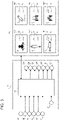
Figure 3 is a schematic representation of an electronic control system for the hydraulic system of the invention. -
Figure 1 discloses a hydraulic circuit 1 for an agricultural vehicle (not shown) comprising pumping means 2 configured to provide a flow of oil at high pressure to fed essential operative systemshydraulic circuits 3 and other operative systemshydraulic circuits 4 of the vehicle. - In particular, the pumping means 2 may be carried in rotation to provide the oil flow by a
torque source 5 such as the internal combustion engine of the vehicle or an electric motor. - The pumping means 2 are fluidly connected by a primary line conduit 6 to the essential operative system
hydraulic circuits 3 and by a secondary line conduit 7 to the other operative systemshydraulic circuits 4. - The essential operative system
hydraulic circuits 3 comprises the transmission hydraulic circuit, the steering hydraulic circuit and the braking hydraulic circuit. - Making reference to
figure 2 , the other operative systemshydraulic circuits 4 comprises at least twooperative circuits 8 and auxiliary valveshydraulic circuit 9. - According to an advantageous configuration, at least two
operative circuits 8 may be chosen among the following: - A
stabilizer system circuit 8a fluidly connected to secondary line 7 via aconduit 11a; - A
hitch system circuit 8b fluidly connected to secondary line 7 via aconduit 11b; - A hydraulic
link system circuit 8c fluidly connected to secondary line 7 via aconduit 11c; - A cabin
suspension system circuit 8d fluidly connected to secondary line 7 via aconduit 11d; and/or - A front
suspension system circuit 8e fluidly connected to secondary line 7 via aconduit 11e. - In particular, it is schematized a singular auxiliary valve in
figure 2 , connected to arespective conduit 12 to the secondary line 7, but it is clear that the auxiliary valveshydraulic circuit 9 comprises different systems controlled by respective valves, e.g. EHR (Electric hydraulic remote) valves. - Furthermore,
figure 2 discloses a vehicle provided with all theoperative system circuits 8a-8e listed above. Clearly some of this latter may be absent or other systems may be present in addition toauxiliary valves 9. - The hydraulic circuit 1 comprises sensor means 13a, 13b, 13c, 13d, 13e, 14 fluidly interposed on
conduits - In particular, the sensor means 13a, 13b, 13c, 13d, 13e, 14 may be configured to detect the flow rate, e.g. via a flow meter, of the pressure of the oil, e.g. via a pressure sensor, flowing in the
respective conduit 11a-11d, 12. - The hydraulic system further comprise an
electronic control unit 16 configured to be electrically connected totorque source 5 and sensor means 13a, 13b, 13c, 13d, 13e, 14 and comprising elaboration means 17 configured to control the operation of the operative systemhydraulic circuits 4 consequently, on the base of the data retrieved of the aforementioned sensor means and execute at least one between the actions i) provide a warning signal and ii) control said torque source (5).. In particular, suchelectronic control unit 16 may be the ECU of the vehicle. - The
electronic control unit 16 is therefore configured to receive as input the following data signals: - Ia' to Ie' retrieved by sensor means 13a- 13e on each of the respective
operative system circuit 8a-8e, that relates to the oil flow/pressure flowing inconduit 11a-11e; - I", retrieved by sensor means 14 on
valves conduit 12, that relates to the oil flow/pressure flowing inconduit 12; and - I‴, coming from
torque source 5 and relating to the power rate provided by this latter to pump 2, i.e. related to the oil flow available in secondary line 7. - The elaboration means 17 are configured to memorize a saturation logic, detailed below, configured to provide as output the following control signals in function of the above input signals:
- Oa' to Oe', configured to manage oil demand in
operative system circuits 8a-8e; - O‴, configured to manage oil demand in
circuit 9;and - O‴, configured to execute at least one between the actions i) provide a warning signal and ii)
control torque source 5. - The saturation logic may provide the following controls:
- If the oil requested by
circuits 8a-8e and 9 exceeds the flow available, execute at least one between the actions i) provide a warning signal and ii)control torque source 5; and; - divide the fluid between the
circuits 8a-8e and 9 proportionally to their flow demand. - The
electronic unit 16 is furthermore electronically connected to user control means 18 configured to allow to the user to vary the priority of the oil to be provided to thecircuits 8a-8e and 9. - Preferably, user control means 18 may comprise a display configured to provide a first touch area U' configured to select the
auxiliary valve circuit 9 and second touch areas U" configured to select the aforementioned at least twooperative system circuits 8a-8e. - More preferably, each touch area U', Ua"-Ue" comprises three sections:
- A graphical section G wherein it is indicated, either by a symbolic or by word, the operative system that may be controlled by acting on such specific touch area;
- A selector section S wherein it is possible to select the related operative system so that fluid may flow into this system circuit; and
- A numerical section N wherein it is possible to input a value of flow, preferably as percentage of the available flow in secondary line 7, to this system circuit.
- Accordingly, the user may select at least one between
auxiliary valve circuit 9 and other presentoperative system circuits 8a-8e, by touching the respective touch area U', Ua"-Ue" to allow the partition of the available fluid to only one or among different circuits, eventually with different value of partition of the oil flow. - Furthermore, the display means may be further configured to show, e.g. via sections S and N listed above, output data Oa'-Oe', O", O‴, i.e. data related to the oil flow flowing to the
operative system circuits 4. - The warning signal may be displayed via user control means 17, and/or via acoustic or lighting means to suggest the user to increase the speed/torque of torque source.
- The warning signal may be present in substitution of the automatic control of the torque source or in combination with this latter, e.g. the automatic control may be set after a preset time interval after the warning signal is provided to the driver.
- The operation of the above described hydraulic circuit provided with an ant saturation system is the following.
- The user controls the vehicle to allow its travel and, in case, the use of certain
operational elements 8a-8e or other systems controlled by theauxiliary valves 9. - Accordingly, the oil flow provided by
pump 2 flows via primary conduit 6 towards the steering, transmission and brakes circuits of the vehicle. The remaining flow is sent via secondary conduit 7 tocircuits 8a-8e and 9 according to the control provided by theelectronic control unit 16, as described above. - If the user presses, via display means, only one between the
operative systems 8a-8b orauxiliary valves 9 of further selected the relative quantity of oil that should flow through this system, theelectronic control unit 16 prioritizes the flow towards the selected systems. - In view of the above, the present invention also relates to a control method for partitioning the oil flow between different operative systems
hydraulic circuits 4 of a secondary line 7 of a vehicle comprising the following steps: - i) Acquiring data related to the oil flow flowing in different
operative systems 8a-8e, 9 of the operative systemshydraulic circuits 4; - ii) Elaborating such data to compare the detected flow with respect to the available flow coming from pump means 2;
- iii) If such detected flow is greater with respect to the available flow, execute at least one between the actions i) provide a warning signal and ii)
control torque source 5 to increase the flow at secondary line 7; - iv) divide the possible flow among the different operative systems
hydraulic circuits 4 in function of their flow demand. - The flow division among the different operative systems
hydraulic circuits 4 may be realized proportionally to the demand of the differentoperative systems 8a-8e, 9. - The above-described method may further comprise the following step:
- v) Acquire input data related to user's request to provide flow to at least one among the operative systems
hydraulic circuits 8a-8e, 9; - vi) Prioritize the flow coming to the secondary line to the selected at least one operative systems hydraulic circuits.
- The method may further comprise a further step before step vi) listed above:
v') Acquire input data related to user's request to specify a relative quantity of flow to at least one among the operative systemshydraulic circuits 8a-8e, 9; - In particular, the acquisition of input data may be executed thanks to display means configured to define touch area that can be pressed by the user to provide the input data. Such display means are furthermore advantageously configured to allow insertion or selection of a number, e.g. a percentage, of flow that may should flow towards the selected
operative system 8a-8e, 9. - The warning signal may be displayed via the aforementioned display means and/or may be an acoustic signal and/or a lighting signal.
- In view of the foregoing, the advantages of a hydraulic circuit and related control method according to the invention are apparent.
- Thanks to the proposed system and control method, it is possible to provide an improved anti saturation logic.
- In particular, it is possible to involve other systems than the auxiliary valves to control the distribution of the available oil flow.
- According to the above, the comfort of the operation of the vehicle is increase; indeed the user may select the behaviors of the anti saturation logic according to the specific work needed.
- Furthermore, the warning signal allows the user to increase the speed/torque provided by torque source. In this way, it may be provided enough fluid to all primary and secondary line systems without the need of dividing this latter, at least within the torque source capabilities.
- If configured, the control unit will automatically increase the speed/torque provided by torque source thereby automatically providing the needed flow via pump carried by the torque source.
- It is clear that modifications can be made to the described hydraulic circuit and related control method which do not extend beyond the scope of protection defined by the claims.
- For example, as said, more auxiliary valves may be present or a different operative system with respect to the hitch circuit. E.g., the user control means 18 may comprise other elements such as buttons instead or the described display.
- Furthermore, the control law described above may be different.
Claims (11)
- Hydraulic circuit (1) for an agricultural vehicle comprising a pump (2) carried by a torque source (5) to provide oil to a primary conduit (6) and to a secondary conduit (7),said primary conduit (6) being fluidly connected to essential operative system hydraulic circuits (3) of said vehicle and said secondary conduit (7) being fluidly connected to other operative systems hydraulic circuits (4) of said vehicle,said other operative systems hydraulic circuits (4) comprising at least two among a stabilizer system circuit (8a), a hitch system circuit (8b), a hydraulic link system circuit (8c), a cabin suspension system circuit (8d) and a front suspension system circuit (8e),each among said circuits (8a-8e) respectively being connected by conduits (11a-11e, 12) to said secondary conduit (7),characterized in that said hydraulic circuit (1) comprises sensor means (13a-13e, 14) interposed on said conduits (11a-11e, 12) and configured to detect oil characteristics of the oil flow flowing into said conduits (11a-11e, 12),said hydraulic circuit (1) being provided by an electronic control unit (16) electrically connected to said sensor means (13a-13e, 14) and to said torque source (5) and comprising elaboration means (17) configured to acquire the data detected by said sensor means (13a-13e, 14) and, in function of said acquired data, to control the oil flow demand of said other operative systems hydraulic circuits (4) and execute at least one between the actions i) provide a warning signal and ii) control said torque source (5).
- Hydraulic circuit according to claim 1, wherein said sensor means (13a-13e, 14) comprises a pressure sensors or a flowmeter sensor.
- Hydraulic circuit according to claims 1 or 2, wherein said electronic control unit (16) is electrically connected to user control means (18) configured to allow the user to control the oil flow priority among said hydraulic circuits (8a-8e, 9).
- Hydraulic circuit according to claim 3, wherein said user control means (18) comprises display means configured to provide a plurality of touch areas (Ua'- Ue', U") each configured to provide a control among said hydraulic circuits (8a-8e, 9).
- Hydraulic circuit according to any of the preceding claims, wherein said elaboration means (17) are configured to receive input data (Ia'- Ie', I") from said sensor means (13a-13e, 14) and input data (I‴) from said torque source (5), said elaboration means (17) providing control outputs (Oa'-Oe' O") for varying the flow demand of said other operative systems hydraulic circuits (4) and/or control outputs (O‴) for executing at least one between the actions i) provide a warning signal and ii) control said torque source (5), in function of said input data (Ia'-Ie', I", I‴).
- Hydraulic circuit according to claims 4 or 5, wherein said elaboration means (17) are configured to electrically connected to user control means (18) to receive user input data, said user input data being elaborated by said elaboration means (17) together with said input data (Ia'-Ie', I", I‴) to provide said output data (Oa'-Oe', Oʺ, O‴).
- Hydraulic circuit according to claim 6, wherein said user control means (18) are configured to display to said user some information related to said output data (Oa'-Oe', O", O‴).
- Hydraulic circuit according to any of the preceding claims, wherein said essential operative system circuits (3) comprises a steering, a braking and a transmission hydraulic circuit of said agricultural vehicle.
- Control method to an oil flow partition between different operative systems hydraulic circuits (4) of a secondary line (7) of a hydraulic circuit according to any of the preceding claims, said control method comprising the following steps:i) Acquiring data related to the oil flow flowing in different operative systems 8a-8e, 9 of the operative systems hydraulic circuits 4;ii) Elaborating such data to compare the detected flow with respect to the available flow coming from pump means 2;iii) If such detected flow is greater with respect to the available flow, executing at least one between the actions i) provide a warning signal and ii) control said torque source (5).;iv) divide the possible flow among the different operative systems hydraulic circuits 4 in function of their flow demand.
- Method according to claim 9, further comprising the following steps:v) Acquire input data related to an user's request to provide flow to at least one among the operative systems hydraulic circuits 8a-8e, 9;vi) Prioritize the flow coming to the secondary line to the selected at least one operative systems hydraulic circuits.
- Method according to claim 10, further comprising the following step between steps v) and vi).
v') Acquire input data related to user's request to specify a relative quantity of flow to at least one among the operative systems hydraulic circuits 8a-8e, 9.
Applications Claiming Priority (1)
| Application Number | Priority Date | Filing Date | Title |
|---|---|---|---|
| IT102021000010601A IT202100010601A1 (en) | 2021-04-27 | 2021-04-27 | HYDRAULIC CIRCUIT FOR AN AGRICULTURAL VEHICLE EQUIPPED WITH AN ANTI-SATURATION SYSTEM AND ANTI-SATURATION CONTROL METHOD |
Publications (2)
| Publication Number | Publication Date |
|---|---|
| EP4083444A1 true EP4083444A1 (en) | 2022-11-02 |
| EP4083444B1 EP4083444B1 (en) | 2024-11-13 |
Family
ID=76708342
Family Applications (1)
| Application Number | Title | Priority Date | Filing Date |
|---|---|---|---|
| EP22170169.1A Active EP4083444B1 (en) | 2021-04-27 | 2022-04-27 | Hydraulic circuit for an agricultural vehicle provided with an anti-saturation system and anti-saturation control method |
Country Status (2)
| Country | Link |
|---|---|
| EP (1) | EP4083444B1 (en) |
| IT (1) | IT202100010601A1 (en) |
Cited By (1)
| Publication number | Priority date | Publication date | Assignee | Title |
|---|---|---|---|---|
| EP4455488A1 (en) * | 2023-04-27 | 2024-10-30 | Deere & Company | Device for operating a load-controlled hydraulic power supply of an agricultural tractor |
Citations (2)
| Publication number | Priority date | Publication date | Assignee | Title |
|---|---|---|---|---|
| DE3319533A1 (en) * | 1983-05-28 | 1984-11-29 | Klöckner-Humboldt-Deutz AG, 5000 Köln | HYDRAULIC CONTROL SYSTEM FOR THE STEERING AND WORKING HYDRAULICS ON VEHICLES |
| EP2554853A1 (en) * | 2010-03-31 | 2013-02-06 | Kubota Corporation | Hydraulic system for service vehicle |
-
2021
- 2021-04-27 IT IT102021000010601A patent/IT202100010601A1/en unknown
-
2022
- 2022-04-27 EP EP22170169.1A patent/EP4083444B1/en active Active
Patent Citations (2)
| Publication number | Priority date | Publication date | Assignee | Title |
|---|---|---|---|---|
| DE3319533A1 (en) * | 1983-05-28 | 1984-11-29 | Klöckner-Humboldt-Deutz AG, 5000 Köln | HYDRAULIC CONTROL SYSTEM FOR THE STEERING AND WORKING HYDRAULICS ON VEHICLES |
| EP2554853A1 (en) * | 2010-03-31 | 2013-02-06 | Kubota Corporation | Hydraulic system for service vehicle |
Cited By (2)
| Publication number | Priority date | Publication date | Assignee | Title |
|---|---|---|---|---|
| EP4455488A1 (en) * | 2023-04-27 | 2024-10-30 | Deere & Company | Device for operating a load-controlled hydraulic power supply of an agricultural tractor |
| US12434760B2 (en) | 2023-04-27 | 2025-10-07 | Deere & Company | Apparatus for operating a load-controlled hydraulic supply of an agricultural tractor |
Also Published As
| Publication number | Publication date |
|---|---|
| IT202100010601A1 (en) | 2022-10-27 |
| EP4083444B1 (en) | 2024-11-13 |
Similar Documents
| Publication | Publication Date | Title |
|---|---|---|
| US20070234718A1 (en) | Hydraulic System and Work Machine Comprising Such a System | |
| US4989925A (en) | Brake pressure control device for vehicles | |
| US8333069B2 (en) | Hydrostatic transmission device for a heavy vehicle | |
| US10428756B2 (en) | Power-economy mode control system for a vehicle | |
| US10040436B2 (en) | Trailer brake pilot control circuit and method of control thereof | |
| EP4083444B1 (en) | Hydraulic circuit for an agricultural vehicle provided with an anti-saturation system and anti-saturation control method | |
| EP3265349B1 (en) | A braking system | |
| WO2015157668A1 (en) | System and method for automatic neutral and automatic return-to-range for use with an automatic transmission | |
| EP3628555B1 (en) | Downhill speed control target adaptation based on engine retarder demand | |
| WO2013041493A1 (en) | Oil level control device | |
| EP4083443B1 (en) | Hydraulic circuit for an agricultural vehicle provided with an anti-saturation system and anti-saturation control method | |
| US20220186794A1 (en) | Actuation method for a hydraulic system with a pump and multiple valves, and hydraulic system | |
| EP2532559B1 (en) | Vehicle braking system | |
| US6640271B2 (en) | Engine ECM multi-input/output configuration | |
| EP3833586B1 (en) | Hydraulic arrangement for hybrid priority valve | |
| US10808733B2 (en) | Open center to open center load sense conversion valve and hydraulic systems therewith | |
| US9676376B2 (en) | Vehicle brake fluid pressure control apparatus | |
| US20160332609A1 (en) | Method for operating a brake system and brake system for a motor vehicle | |
| US20070260382A1 (en) | Control System for a Vehicle | |
| EP1839979B1 (en) | Vehicular brake hydraulic control device | |
| EP4606661A1 (en) | Hydraulic braking arrangement for work vehicles and related control method | |
| EP4470875B1 (en) | Improved hydraulic arrangement for a work vehicle | |
| EP4671063A1 (en) | HYDRAULIC BRAKE CONTROL SYSTEM AND METHOD FOR A WORK VEHICLE AND A TRAILER | |
| US8657390B2 (en) | Vehicle brake fluid pressure control apparatus | |
| EP1355067B1 (en) | Load sensing hydraulic system |
Legal Events
| Date | Code | Title | Description |
|---|---|---|---|
| PUAI | Public reference made under article 153(3) epc to a published international application that has entered the european phase |
Free format text: ORIGINAL CODE: 0009012 |
|
| STAA | Information on the status of an ep patent application or granted ep patent |
Free format text: STATUS: THE APPLICATION HAS BEEN PUBLISHED |
|
| AK | Designated contracting states |
Kind code of ref document: A1 Designated state(s): AL AT BE BG CH CY CZ DE DK EE ES FI FR GB GR HR HU IE IS IT LI LT LU LV MC MK MT NL NO PL PT RO RS SE SI SK SM TR |
|
| STAA | Information on the status of an ep patent application or granted ep patent |
Free format text: STATUS: REQUEST FOR EXAMINATION WAS MADE |
|
| 17P | Request for examination filed |
Effective date: 20230502 |
|
| RBV | Designated contracting states (corrected) |
Designated state(s): AL AT BE BG CH CY CZ DE DK EE ES FI FR GB GR HR HU IE IS IT LI LT LU LV MC MK MT NL NO PL PT RO RS SE SI SK SM TR |
|
| RAP3 | Party data changed (applicant data changed or rights of an application transferred) |
Owner name: CNH INDUSTRIAL ITALIA S.P.A. |
|
| GRAP | Despatch of communication of intention to grant a patent |
Free format text: ORIGINAL CODE: EPIDOSNIGR1 |
|
| STAA | Information on the status of an ep patent application or granted ep patent |
Free format text: STATUS: GRANT OF PATENT IS INTENDED |
|
| INTG | Intention to grant announced |
Effective date: 20240603 |
|
| GRAS | Grant fee paid |
Free format text: ORIGINAL CODE: EPIDOSNIGR3 |
|
| GRAA | (expected) grant |
Free format text: ORIGINAL CODE: 0009210 |
|
| STAA | Information on the status of an ep patent application or granted ep patent |
Free format text: STATUS: THE PATENT HAS BEEN GRANTED |
|
| AK | Designated contracting states |
Kind code of ref document: B1 Designated state(s): AL AT BE BG CH CY CZ DE DK EE ES FI FR GB GR HR HU IE IS IT LI LT LU LV MC MK MT NL NO PL PT RO RS SE SI SK SM TR |
|
| REG | Reference to a national code |
Ref country code: GB Ref legal event code: FG4D |
|
| REG | Reference to a national code |
Ref country code: CH Ref legal event code: EP |
|
| REG | Reference to a national code |
Ref country code: IE Ref legal event code: FG4D |
|
| REG | Reference to a national code |
Ref country code: DE Ref legal event code: R096 Ref document number: 602022007618 Country of ref document: DE |
|
| REG | Reference to a national code |
Ref country code: LT Ref legal event code: MG9D |
|
| REG | Reference to a national code |
Ref country code: NL Ref legal event code: MP Effective date: 20241113 |
|
| PG25 | Lapsed in a contracting state [announced via postgrant information from national office to epo] |
Ref country code: IS Free format text: LAPSE BECAUSE OF FAILURE TO SUBMIT A TRANSLATION OF THE DESCRIPTION OR TO PAY THE FEE WITHIN THE PRESCRIBED TIME-LIMIT Effective date: 20250313 Ref country code: PT Free format text: LAPSE BECAUSE OF FAILURE TO SUBMIT A TRANSLATION OF THE DESCRIPTION OR TO PAY THE FEE WITHIN THE PRESCRIBED TIME-LIMIT Effective date: 20250313 Ref country code: HR Free format text: LAPSE BECAUSE OF FAILURE TO SUBMIT A TRANSLATION OF THE DESCRIPTION OR TO PAY THE FEE WITHIN THE PRESCRIBED TIME-LIMIT Effective date: 20241113 |
|
| PG25 | Lapsed in a contracting state [announced via postgrant information from national office to epo] |
Ref country code: FI Free format text: LAPSE BECAUSE OF FAILURE TO SUBMIT A TRANSLATION OF THE DESCRIPTION OR TO PAY THE FEE WITHIN THE PRESCRIBED TIME-LIMIT Effective date: 20241113 Ref country code: NL Free format text: LAPSE BECAUSE OF FAILURE TO SUBMIT A TRANSLATION OF THE DESCRIPTION OR TO PAY THE FEE WITHIN THE PRESCRIBED TIME-LIMIT Effective date: 20241113 |
|
| REG | Reference to a national code |
Ref country code: AT Ref legal event code: MK05 Ref document number: 1741875 Country of ref document: AT Kind code of ref document: T Effective date: 20241113 |
|
| PG25 | Lapsed in a contracting state [announced via postgrant information from national office to epo] |
Ref country code: BG Free format text: LAPSE BECAUSE OF FAILURE TO SUBMIT A TRANSLATION OF THE DESCRIPTION OR TO PAY THE FEE WITHIN THE PRESCRIBED TIME-LIMIT Effective date: 20241113 |
|
| PG25 | Lapsed in a contracting state [announced via postgrant information from national office to epo] |
Ref country code: ES Free format text: LAPSE BECAUSE OF FAILURE TO SUBMIT A TRANSLATION OF THE DESCRIPTION OR TO PAY THE FEE WITHIN THE PRESCRIBED TIME-LIMIT Effective date: 20241113 |
|
| PG25 | Lapsed in a contracting state [announced via postgrant information from national office to epo] |
Ref country code: NO Free format text: LAPSE BECAUSE OF FAILURE TO SUBMIT A TRANSLATION OF THE DESCRIPTION OR TO PAY THE FEE WITHIN THE PRESCRIBED TIME-LIMIT Effective date: 20250213 |
|
| PG25 | Lapsed in a contracting state [announced via postgrant information from national office to epo] |
Ref country code: LV Free format text: LAPSE BECAUSE OF FAILURE TO SUBMIT A TRANSLATION OF THE DESCRIPTION OR TO PAY THE FEE WITHIN THE PRESCRIBED TIME-LIMIT Effective date: 20241113 Ref country code: GR Free format text: LAPSE BECAUSE OF FAILURE TO SUBMIT A TRANSLATION OF THE DESCRIPTION OR TO PAY THE FEE WITHIN THE PRESCRIBED TIME-LIMIT Effective date: 20250214 Ref country code: AT Free format text: LAPSE BECAUSE OF FAILURE TO SUBMIT A TRANSLATION OF THE DESCRIPTION OR TO PAY THE FEE WITHIN THE PRESCRIBED TIME-LIMIT Effective date: 20241113 |
|
| PG25 | Lapsed in a contracting state [announced via postgrant information from national office to epo] |
Ref country code: PL Free format text: LAPSE BECAUSE OF FAILURE TO SUBMIT A TRANSLATION OF THE DESCRIPTION OR TO PAY THE FEE WITHIN THE PRESCRIBED TIME-LIMIT Effective date: 20241113 |
|
| PG25 | Lapsed in a contracting state [announced via postgrant information from national office to epo] |
Ref country code: RS Free format text: LAPSE BECAUSE OF FAILURE TO SUBMIT A TRANSLATION OF THE DESCRIPTION OR TO PAY THE FEE WITHIN THE PRESCRIBED TIME-LIMIT Effective date: 20250213 |
|
| PG25 | Lapsed in a contracting state [announced via postgrant information from national office to epo] |
Ref country code: SM Free format text: LAPSE BECAUSE OF FAILURE TO SUBMIT A TRANSLATION OF THE DESCRIPTION OR TO PAY THE FEE WITHIN THE PRESCRIBED TIME-LIMIT Effective date: 20241113 |
|
| PG25 | Lapsed in a contracting state [announced via postgrant information from national office to epo] |
Ref country code: DK Free format text: LAPSE BECAUSE OF FAILURE TO SUBMIT A TRANSLATION OF THE DESCRIPTION OR TO PAY THE FEE WITHIN THE PRESCRIBED TIME-LIMIT Effective date: 20241113 |
|
| PG25 | Lapsed in a contracting state [announced via postgrant information from national office to epo] |
Ref country code: EE Free format text: LAPSE BECAUSE OF FAILURE TO SUBMIT A TRANSLATION OF THE DESCRIPTION OR TO PAY THE FEE WITHIN THE PRESCRIBED TIME-LIMIT Effective date: 20241113 |
|
| PG25 | Lapsed in a contracting state [announced via postgrant information from national office to epo] |
Ref country code: RO Free format text: LAPSE BECAUSE OF FAILURE TO SUBMIT A TRANSLATION OF THE DESCRIPTION OR TO PAY THE FEE WITHIN THE PRESCRIBED TIME-LIMIT Effective date: 20241113 |
|
| PG25 | Lapsed in a contracting state [announced via postgrant information from national office to epo] |
Ref country code: SK Free format text: LAPSE BECAUSE OF FAILURE TO SUBMIT A TRANSLATION OF THE DESCRIPTION OR TO PAY THE FEE WITHIN THE PRESCRIBED TIME-LIMIT Effective date: 20241113 |
|
| PG25 | Lapsed in a contracting state [announced via postgrant information from national office to epo] |
Ref country code: CZ Free format text: LAPSE BECAUSE OF FAILURE TO SUBMIT A TRANSLATION OF THE DESCRIPTION OR TO PAY THE FEE WITHIN THE PRESCRIBED TIME-LIMIT Effective date: 20241113 |
|
| REG | Reference to a national code |
Ref country code: DE Ref legal event code: R097 Ref document number: 602022007618 Country of ref document: DE |
|
| PG25 | Lapsed in a contracting state [announced via postgrant information from national office to epo] |
Ref country code: SE Free format text: LAPSE BECAUSE OF FAILURE TO SUBMIT A TRANSLATION OF THE DESCRIPTION OR TO PAY THE FEE WITHIN THE PRESCRIBED TIME-LIMIT Effective date: 20241113 |
|
| PLBE | No opposition filed within time limit |
Free format text: ORIGINAL CODE: 0009261 |
|
| STAA | Information on the status of an ep patent application or granted ep patent |
Free format text: STATUS: NO OPPOSITION FILED WITHIN TIME LIMIT |
|
| 26N | No opposition filed |
Effective date: 20250814 |
|
| REG | Reference to a national code |
Ref country code: CH Ref legal event code: H13 Free format text: ST27 STATUS EVENT CODE: U-0-0-H10-H13 (AS PROVIDED BY THE NATIONAL OFFICE) Effective date: 20251125 |
|
| PG25 | Lapsed in a contracting state [announced via postgrant information from national office to epo] |
Ref country code: LU Free format text: LAPSE BECAUSE OF NON-PAYMENT OF DUE FEES Effective date: 20250427 |
|
| PG25 | Lapsed in a contracting state [announced via postgrant information from national office to epo] |
Ref country code: MC Free format text: LAPSE BECAUSE OF FAILURE TO SUBMIT A TRANSLATION OF THE DESCRIPTION OR TO PAY THE FEE WITHIN THE PRESCRIBED TIME-LIMIT Effective date: 20241113 |
|
| REG | Reference to a national code |
Ref country code: BE Ref legal event code: MM Effective date: 20250430 |
|
| PG25 | Lapsed in a contracting state [announced via postgrant information from national office to epo] |
Ref country code: BE Free format text: LAPSE BECAUSE OF NON-PAYMENT OF DUE FEES Effective date: 20250430 |
|
| PG25 | Lapsed in a contracting state [announced via postgrant information from national office to epo] |
Ref country code: CH Free format text: LAPSE BECAUSE OF NON-PAYMENT OF DUE FEES Effective date: 20250430 |
|
| PG25 | Lapsed in a contracting state [announced via postgrant information from national office to epo] |
Ref country code: IE Free format text: LAPSE BECAUSE OF NON-PAYMENT OF DUE FEES Effective date: 20250427 |
|
| PG25 | Lapsed in a contracting state [announced via postgrant information from national office to epo] |
Ref country code: CY Free format text: LAPSE BECAUSE OF FAILURE TO SUBMIT A TRANSLATION OF THE DESCRIPTION OR TO PAY THE FEE WITHIN THE PRESCRIBED TIME-LIMIT Effective date: 20241113 |
|
| PG25 | Lapsed in a contracting state [announced via postgrant information from national office to epo] |
Ref country code: LT Free format text: LAPSE BECAUSE OF FAILURE TO SUBMIT A TRANSLATION OF THE DESCRIPTION OR TO PAY THE FEE WITHIN THE PRESCRIBED TIME-LIMIT Effective date: 20241113 |
|
| PGFP | Annual fee paid to national office [announced via postgrant information from national office to epo] |
Ref country code: GB Payment date: 20260421 Year of fee payment: 5 |
|
| PGFP | Annual fee paid to national office [announced via postgrant information from national office to epo] |
Ref country code: IT Payment date: 20260422 Year of fee payment: 5 |
|
| PGFP | Annual fee paid to national office [announced via postgrant information from national office to epo] |
Ref country code: DE Payment date: 20260421 Year of fee payment: 5 |
|
| PGFP | Annual fee paid to national office [announced via postgrant information from national office to epo] |
Ref country code: FR Payment date: 20260423 Year of fee payment: 5 |