EP4083429A1 - Scroll compressor comprising oil separation member - Google Patents
Scroll compressor comprising oil separation member Download PDFInfo
- Publication number
- EP4083429A1 EP4083429A1 EP21747932.8A EP21747932A EP4083429A1 EP 4083429 A1 EP4083429 A1 EP 4083429A1 EP 21747932 A EP21747932 A EP 21747932A EP 4083429 A1 EP4083429 A1 EP 4083429A1
- Authority
- EP
- European Patent Office
- Prior art keywords
- inclined surface
- fixed leg
- oil
- separation member
- scroll compressor
- Prior art date
- Legal status (The legal status is an assumption and is not a legal conclusion. Google has not performed a legal analysis and makes no representation as to the accuracy of the status listed.)
- Granted
Links
Images


Classifications
-
- F—MECHANICAL ENGINEERING; LIGHTING; HEATING; WEAPONS; BLASTING
- F04—POSITIVE - DISPLACEMENT MACHINES FOR LIQUIDS; PUMPS FOR LIQUIDS OR ELASTIC FLUIDS
- F04C—ROTARY-PISTON, OR OSCILLATING-PISTON, POSITIVE-DISPLACEMENT MACHINES FOR LIQUIDS; ROTARY-PISTON, OR OSCILLATING-PISTON, POSITIVE-DISPLACEMENT PUMPS
- F04C18/00—Rotary-piston pumps specially adapted for elastic fluids
- F04C18/02—Rotary-piston pumps specially adapted for elastic fluids of arcuate-engagement type, i.e. with circular translatory movement of co-operating members, each member having the same number of teeth or tooth-equivalents
- F04C18/0207—Rotary-piston pumps specially adapted for elastic fluids of arcuate-engagement type, i.e. with circular translatory movement of co-operating members, each member having the same number of teeth or tooth-equivalents both members having co-operating elements in spiral form
- F04C18/0215—Rotary-piston pumps specially adapted for elastic fluids of arcuate-engagement type, i.e. with circular translatory movement of co-operating members, each member having the same number of teeth or tooth-equivalents both members having co-operating elements in spiral form where only one member is moving
-
- F—MECHANICAL ENGINEERING; LIGHTING; HEATING; WEAPONS; BLASTING
- F04—POSITIVE - DISPLACEMENT MACHINES FOR LIQUIDS; PUMPS FOR LIQUIDS OR ELASTIC FLUIDS
- F04C—ROTARY-PISTON, OR OSCILLATING-PISTON, POSITIVE-DISPLACEMENT MACHINES FOR LIQUIDS; ROTARY-PISTON, OR OSCILLATING-PISTON, POSITIVE-DISPLACEMENT PUMPS
- F04C29/00—Component parts, details or accessories of pumps or pumping installations, not provided for in groups F04C18/00 - F04C28/00
- F04C29/02—Lubrication; Lubricant separation
- F04C29/026—Lubricant separation
-
- F—MECHANICAL ENGINEERING; LIGHTING; HEATING; WEAPONS; BLASTING
- F04—POSITIVE - DISPLACEMENT MACHINES FOR LIQUIDS; PUMPS FOR LIQUIDS OR ELASTIC FLUIDS
- F04C—ROTARY-PISTON, OR OSCILLATING-PISTON, POSITIVE-DISPLACEMENT MACHINES FOR LIQUIDS; ROTARY-PISTON, OR OSCILLATING-PISTON, POSITIVE-DISPLACEMENT PUMPS
- F04C2240/00—Components
- F04C2240/30—Casings or housings
-
- F—MECHANICAL ENGINEERING; LIGHTING; HEATING; WEAPONS; BLASTING
- F04—POSITIVE - DISPLACEMENT MACHINES FOR LIQUIDS; PUMPS FOR LIQUIDS OR ELASTIC FLUIDS
- F04C—ROTARY-PISTON, OR OSCILLATING-PISTON, POSITIVE-DISPLACEMENT MACHINES FOR LIQUIDS; ROTARY-PISTON, OR OSCILLATING-PISTON, POSITIVE-DISPLACEMENT PUMPS
- F04C2240/00—Components
- F04C2240/40—Electric motor
-
- F—MECHANICAL ENGINEERING; LIGHTING; HEATING; WEAPONS; BLASTING
- F04—POSITIVE - DISPLACEMENT MACHINES FOR LIQUIDS; PUMPS FOR LIQUIDS OR ELASTIC FLUIDS
- F04C—ROTARY-PISTON, OR OSCILLATING-PISTON, POSITIVE-DISPLACEMENT MACHINES FOR LIQUIDS; ROTARY-PISTON, OR OSCILLATING-PISTON, POSITIVE-DISPLACEMENT PUMPS
- F04C23/00—Combinations of two or more pumps, each being of rotary-piston or oscillating-piston type, specially adapted for elastic fluids; Pumping installations specially adapted for elastic fluids; Multi-stage pumps specially adapted for elastic fluids
- F04C23/008—Hermetic pumps
-
- F—MECHANICAL ENGINEERING; LIGHTING; HEATING; WEAPONS; BLASTING
- F04—POSITIVE - DISPLACEMENT MACHINES FOR LIQUIDS; PUMPS FOR LIQUIDS OR ELASTIC FLUIDS
- F04C—ROTARY-PISTON, OR OSCILLATING-PISTON, POSITIVE-DISPLACEMENT MACHINES FOR LIQUIDS; ROTARY-PISTON, OR OSCILLATING-PISTON, POSITIVE-DISPLACEMENT PUMPS
- F04C29/00—Component parts, details or accessories of pumps or pumping installations, not provided for in groups F04C18/00 - F04C28/00
- F04C29/02—Lubrication; Lubricant separation
- F04C29/023—Lubricant distribution through a hollow driving shaft
Definitions
- the present disclosure relates to a scroll compressor including an oil separation member that separates refrigerant from oil.
- a scroll compressor disclosed in Patent Literature 1 JP 2015-105637 A ) includes an oil separation plate.
- the oil separation plate suppresses scattering of lubricating oil that can be caused by a refrigerant gas contacting an oil reservoir.
- the oil separation plate is fixed to a lower bearing member.
- the lower bearing member has three legs. The three legs are fixed to an inner peripheral face of a casing.
- a refrigerant discharged from a compression mechanism contains the lubricating oil.
- the refrigerant then moves to near the lower bearing member. There, the refrigerant receives a force from a rotating rotor and swirls in a circumferential direction of the casing along the oil separation plate. As the refrigerant swirls, the lubricating oil is separated from the refrigerant by cyclone separation.
- the refrigerant swirling in the circumferential direction of the casing along the oil separation plate may contact the legs of the lower bearing member. At this time, swirling of the refrigerant is stopped, and separation of the lubricating oil from the refrigerant is inhibited. In this case, a phenomenon called "oil loss" occurs more significantly in which the refrigerant is discharged to outside of the scroll compressor while containing the lubricating oil. As a result, an amount of the lubricating oil in the scroll compressor may be insufficient.
- a scroll compressor includes a casing, a scroll compression mechanism, a motor, a crankshaft, a bearing, a frame, and an oil separation member.
- the scroll compression mechanism is disposed in the casing.
- the motor is disposed in the casing and below the scroll compression mechanism.
- the motor includes a stator and a rotor. The rotor rotates in a rotational direction.
- the crankshaft connects the scroll compression mechanism and the motor.
- the bearing is disposed below the motor.
- the bearing rotatably supports the crankshaft.
- the frame is fixed to the casing.
- the frame supports the bearing.
- the oil separation member is fixed to the frame. The oil separation member suppresses mixing of a refrigerant and a lubricating oil in the casing.
- the frame includes a first fixed leg and a second fixed leg which are fixed to the casing.
- the oil separation member has a first horizontal surface and a first inclined surface.
- the first inclined surface has a first inclined surface upstream portion and a first inclined surface downstream portion in a rotational direction.
- the first inclined surface downstream portion is disposed higher than the first inclined surface upstream portion.
- the first horizontal surface, the first inclined surface, and the first fixed leg are disposed in that order from upstream to downstream in the rotational direction.
- a scroll compressor according to a second aspect is the scroll compressor according to the first aspect, in which the oil separation member further has a second horizontal surface.
- the first horizontal surface, the first inclined surface, the second horizontal surface, and the first fixed leg are disposed in that order from upstream to downstream in the rotational direction.
- the oil separation member has the second horizontal surface. Therefore, the oil separation member can be easily manufactured as compared with a case where an inclined surface is formed at a place where the second horizontal surface is to be provided.
- a scroll compressor according to a third aspect is the scroll compressor according to the second aspect, the scroll compressor further including an oil return passage.
- the oil return passage guides the lubricating oil from above the motor to below the motor.
- the oil separation member further has a third horizontal surface.
- the third horizontal surface includes an oil return passage portion.
- the oil return passage portion is located immediately below the oil return passage.
- the third horizontal surface and the second fixed leg are disposed in that order from upstream to downstream in the rotational direction.
- a scroll compressor according to a fourth aspect is the scroll compressor according to the third aspect, in which the stator further includes a core cut.
- the core cut is located on an outer periphery of the stator.
- the oil return passage includes the core cut.
- the oil return passage includes the core cut. Therefore, a dedicated member constituting the oil return passage is not required at a height of the motor.
- a scroll compressor according to a fifth aspect is the scroll compressor according to the fourth aspect, in which the first inclined surface upstream portion and the first inclined surface downstream portion are separated from each other by a first height difference H1.
- the first inclined surface upstream portion and the first inclined surface downstream portion are separated from each other in a circumferential direction by a first circumferential distance L1.
- the first fixed leg has a first fixed leg upper surface.
- the second horizontal surface and the first fixed leg upper surface are separated from each other by a second height difference H2.
- the second horizontal surface extends in the circumferential direction by a second circumferential distance L2.
- a first inclination H1/L1 which is a ratio of the first height difference H1 to the first circumferential distance L1 is larger than a second inclination H2/L2 which is a ratio of the second height difference H2 to the second circumferential distance L2.
- the first inclination is larger than the second inclination. Therefore, since an advancing direction of the refrigerant flow is set obliquely upward by the first inclined surface, the refrigerant flow can be prevented from colliding with the first fixed leg.
- a scroll compressor according to a sixth aspect is the scroll compressor according to the fifth aspect, in which the first inclination H1/L1 is 0.5 or more and 2.0 or less.
- This configuration designates a range of the first inclination. It is therefore easy to manufacture the oil separation member.
- a scroll compressor according to a seventh aspect is the scroll compressor according to the fifth or sixth aspect, in which the second inclination H2/L2 is 0.3 or more and 1.0 or less.
- This configuration designates a range of the second inclination. It is therefore easy to manufacture the frame.
- a scroll compressor according to an eighth aspect is the scroll compressor according to any one of the first to seventh aspects, in which the oil separation member further has a second inclined surface.
- the second inclined surface has a second inclined surface upstream portion and a second inclined surface downstream portion in the rotational direction.
- the second inclined surface downstream portion is disposed lower than the second inclined surface upstream portion.
- the first fixed leg and the second inclined surface are disposed in that order from upstream to downstream in the rotational direction.
- the second inclined surface having an inclination opposite to an inclination of the first inclined surface is provided downstream of the first fixed leg. Therefore, a structure of the oil separation member can be simplified.
- a scroll compressor according to a ninth aspect is the scroll compressor according to any one of the first to eighth aspects, in which the oil separation member further has a third inclined surface.
- the third inclined surface is inclined in a cross section in a radial direction of the oil separation member.
- the third inclined surface is high on an inner side in the radial direction and low on an outer side in the radial direction.
- the oil separation member has the third inclined surface which is an inclination in the radial direction. Therefore, a level difference formed by the first horizontal surface and the second horizontal surface is absorbed by the third inclined surface.
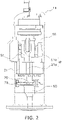
- FIG. 1 is a sectional view of a scroll compressor 10 according to a basic embodiment.
- the scroll compressor 10 compresses a low-pressure refrigerant as a fluid to generate a high-pressure refrigerant.
- the scroll compressor 10 includes a casing 11, a motor 20, a crankshaft 30, a scroll compression mechanism 40, an upper frame 50, a lower frame 60, an oil separation member 70, an oil guide 51 ( FIG. 2 ), and a refrigerant guide 52 ( FIG. 3 ).
- the casing 11 accommodates various components of the scroll compressor 10.
- the casing 11 includes a barrel 11a, an upper portion 11b, and a lower portion 11c.
- the barrel 11a has a substantially cylindrical shape.
- the upper portion 11b and the lower portion 11c are airtightly joined to the barrel 11a.
- the upper portion 11b is provided with a suction pipe 15.
- the barrel 11a is provided with a discharge pipe 16.
- An oil reservoir 12 that stores lubricating oil is provided near the lower portion 11c.
- the motor 20 generates power for driving the scroll compression mechanism 40.
- the motor 20 is disposed in the casing 11.
- the motor 20 is disposed below the scroll compression mechanism 40.
- the motor 20 includes a stator 21 and a rotor 22.
- the stator 21 includes coils (not illustrated). The coils convert power received by the scroll compressor 10 into magnetic force.
- the stator 21 has a substantially cylindrical shape.
- the stator 21 is fixed to the barrel 11a.
- the stator 21 has on its outer periphery a notch called a core cut 21a.
- a gap formed by the core cut 21a between the barrel 11a and the stator 21 functions as a passage for the refrigerant.
- the rotor 22 is disposed near the stator 21.
- the rotor 22 includes a permanent magnet (not illustrated).
- the rotor 22 has a substantially cylindrical shape. The coils of the stator 21 and the permanent magnet of the rotor 22 interact with each other to rotate the rotor 22.
- the crankshaft 30 transmits power generated by the motor 20 to the scroll compression mechanism 40.
- the crankshaft 30 connects the scroll compression mechanism 40 and the motor 20.
- the crankshaft 30 is fixed to the rotor 22.
- the crankshaft 30 has a concentric portion 31 and an eccentric portion 32.
- the concentric portion 31 is concentric with an axis of the rotor 22 and the crankshaft 30.
- the eccentric portion 32 is eccentric from the axis.
- the concentric portion 31 is rotatably supported by an upper bearing 35 and a lower bearing 36.
- the eccentric portion 32 is rotatably supported by an eccentric bearing 37.
- the upper bearing 35 is disposed above the motor 20.
- the lower bearing 36 is disposed below the motor 20.
- the eccentric bearing 37 is disposed near the scroll compression mechanism 40.
- An oil ascending hole 33 is provided inside the crankshaft 30. As the crankshaft 30 rotates, the lubricating oil in the oil reservoir 12 is sucked up into the oil ascending hole 33 and then supplied to the scroll compression mechanism 40, the upper bearing 35, the lower bearing 36, and the eccentric bearing 37.
- the scroll compression mechanism 40 is disposed in the casing 11.
- the scroll compression mechanism 40 includes a fixed scroll 41 and a movable scroll 42.
- the fixed scroll 41 includes a fixed plate 41a and a fixed wrap 41b.
- the fixed plate 41a is a part extending in a horizontal direction.
- the fixed wrap 41b extends in a vertical direction from the fixed plate 41a.
- the fixed wrap 41b has a spiral shape in plan view.
- a discharge hole 45 for discharging a high-pressure refrigerant is formed at a center of the fixed plate 41a.
- the movable scroll 42 includes a movable plate 42a, a movable wrap 42b, and a movable protrusion 42c.
- the movable plate 42a is a part extending in the horizontal direction.
- the movable wrap 42b extends in the vertical direction from the movable plate 42a.
- the movable wrap 42b has a spiral shape in plan view.
- the movable protrusion 42c extends in the vertical direction from the movable plate 42a.
- the movable protrusion 42c has a concave portion. The concave portion accommodates the eccentric bearing 37 and the eccentric portion 32.
- the movable scroll 42 can revolve around the fixed scroll 41.
- the fixed scroll 41 and the movable scroll 42 together define a plurality of compression chambers 43.
- the compression chamber 43 at an outermost position communicates with the suction pipe 15.
- the upper frame 50 supports the upper bearing 35.
- the upper frame 50 supports the crankshaft 30 via the upper bearing 35.
- the upper frame 50 is fixed to the barrel 11a of the casing 11.
- the fixed scroll 41 is fixed to the upper frame 50.
- the upper frame 50 is provided with a refrigerant passage 50a vertically penetrating the upper frame 50.
- the lower frame 60 supports the lower bearing 36.
- the lower frame 60 supports the crankshaft 30 via the lower bearing 36.
- the lower frame 60 is fixed to the barrel 11a of the casing 11.
- the oil separation member 70 suppresses mixing of the refrigerant and the lubricating oil. That is, the oil separation member 70 suppresses scattering of the lubricating oil that may be caused by the gas refrigerant contacting the oil reservoir 12, and thus suppresses mixing of the refrigerant and the lubricating oil.
- the oil separation member 70 is fixed to the lower frame 60.
- FIG. 2 is a side view of some components of the scroll compressor 10.
- the oil guide 51 is provided on the barrel 11a of the casing 11.
- the oil guide 51 is provided with a groove 51a.
- the groove 51a guides the lubricating oil located above downward.
- the groove 51a of the oil guide 51 and the core cut 21a of the stator 21 constitute an oil return passage P.
- the oil return passage P guides the lubricating oil from above the motor 20 to below the motor 20.
- the lubricating oil located above the oil guide 51 passes through the oil return passage P and then falls to an oil return passage portion 79 of the oil separation member 70.
- the oil return passage portion 79 is located immediately below the oil return passage P.
- FIG. 3 is a side view of some components of the scroll compressor 10.
- the refrigerant guide 52 is provided on the barrel 11a of the casing 11.
- the refrigerant guide 52 guides the refrigerant located above in a circumferential direction and downward. As a result, part of the refrigerant swirls along an inner peripheral surface of the barrel 11a while advancing in the horizontal direction. Another part of the refrigerant advances downward and passes through the core cut 21a.
- Movements of the refrigerant and the lubricating oil will be described below. It should be noted that the refrigerant and the lubricating oil do not move completely independently of each other. The refrigerant and the lubricating oil exhibit compatibility. Thus, the movement of the refrigerant or the lubricating oil discussed below may also be movement of a mixture of the refrigerant and lubricating oil.
- the low-pressure refrigerant enters the scroll compressor 10 from the suction pipe 15 illustrated in FIG. 1 .
- the low-pressure refrigerant then enters the compression chamber 43 at the outermost position of the scroll compression mechanism 40.
- the compression chamber 43 moves to a center of the scroll compression mechanism 40 while reducing the volume.
- the low-pressure refrigerant is compressed to become a high-pressure refrigerant.
- the high-pressure refrigerant exits from the discharge hole 45 to an upper space S1. Thereafter, the high-pressure refrigerant reaches a middle space S2 by passing through the refrigerant passage 50a of the upper frame 50.
- the high-pressure refrigerant then reaches the refrigerant guide 52.
- the refrigerant guide 52 allows part of the refrigerant to swirl along an inner periphery of the barrel 11a while advancing in the horizontal direction. This swirling flow may be further accelerated by the rotation of the rotor 22. Another part of the refrigerant advances downward, passes through the core cut 21a, and collides with the oil separation member 70. Next, in a lower space S3 between the motor 20 and the lower frame 60, the rotation of the rotor 22 swirls the refrigerant.
- the lubricating oil is sucked up from the oil reservoir 12 to the oil ascending hole 33. Thereafter, the lubricating oil is supplied to the scroll compression mechanism 40, the upper bearing 35, the lower bearing 36, and the eccentric bearing 37. Subsequently, the lubricating oil exits the scroll compression mechanism 40, the upper bearing 35, the lower bearing 36, and the eccentric bearing 37. Next, the lubricating oil moves downward along the inner peripheral surface of the barrel 11a or the oil return passage P of the oil guide 51. The lubricating oil having exited the oil return passage P falls from the core cut 21a to the oil return passage portion 79 of the oil separation member 70.
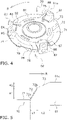
- FIG. 4 is a perspective view of the lower frame 60 and the oil separation member 70. An arrow in the drawing indicates a rotational direction R of the rotor 22.
- the lower frame 60 includes a first fixed leg 61, a second fixed leg 62, and a third fixed leg 63.
- the first fixed leg 61, the second fixed leg 62, and the third fixed leg 63 are all fixed to the barrel 11a of the casing 11.
- a method of fixing is, for example, welding.
- the first fixed leg 61 has a first fixed leg upper surface 61a.
- the oil separation member 70 is a plate-shaped member fixed to the lower frame 60.
- a first horizontal surface 71, a second horizontal surface 73, a third horizontal surface 74, a fourth horizontal surface 81, a fifth horizontal surface 83, a sixth horizontal surface 84, a seventh horizontal surface 86, an eighth horizontal surface 88, a first inclined surface 72, a second inclined surface 75, a third inclined surface 82, a fourth inclined surface 85, a fifth inclined surface 87, and a notch 76 are formed at a position close to an outer periphery of the oil separation member 70.
- the notch 76 allows the lubricating oil accumulated on the oil separation member 70 to fall into the oil reservoir 12.
- the first horizontal surface 71, the first inclined surface 72, the second horizontal surface 73, the first fixed leg 61, and the second inclined surface 75 are disposed in that order from upstream to downstream in the rotational direction R.
- the third horizontal surface 74 and the second fixed leg 62 are disposed in that order from upstream to downstream in the rotational direction R.
- FIG. 5 is a schematic diagram of a periphery of the first inclined surface 72.
- An upstream side of the first inclined surface 72 is a first inclined surface upstream portion 72a.
- a downstream side of the first inclined surface 72 is a first inclined surface downstream portion 72b.
- the first inclined surface downstream portion 72b is disposed higher than the first inclined surface upstream portion 72a.
- the first inclined surface upstream portion 72a and the first inclined surface downstream portion 72b are separated from each other by a first height difference H1.
- the first inclined surface upstream portion 72a and the first inclined surface downstream portion 72b are separated from each other in the circumferential direction by a first circumferential distance L1.
- the second horizontal surface 73 and the first fixed leg upper surface 61a are separated from each other by a second height difference H2.
- the second horizontal surface 73 extends in the circumferential direction by a second circumferential distance L2.
- a ratio of the first height difference H1 to the first circumferential distance L1 is a first inclination H1/L1.
- a ratio of the second height difference H2 to the second circumferential distance L2 is a second inclination H2/L2.
- the first inclination H1/L1 is larger than the second inclination H2/L2.
- the first inclination H1/L1 is 0.5 or more and 2.0 or less.
- the second inclination H2/L2 is 0.3 or more and 1.0 or less.
- FIG. 6 is a schematic diagram of a periphery of the second inclined surface 75.
- An upstream side of the second inclined surface 75 is a second inclined surface upstream portion 75a.
- a downstream side of the second inclined surface 75 is a second inclined surface downstream portion 75b.
- the second inclined surface downstream portion 75b is disposed lower than the second inclined surface upstream portion 75a.
- a third inclined surface 78 is formed on the oil separation member 70.
- the third inclined surface 78 is inclined in a cross section in a radial direction of the oil separation member 70.
- the third inclined surface 78 is high on an inner side in the radial direction and low on an outer side in the radial direction.
- the circumferential distance L2 of the second horizontal surface 73 is set to be larger than the circumferential distance of the fifth horizontal surface 83. This is because the first horizontal surface 71 located upstream of the second horizontal surface 73 is located below the refrigerant guide 52. The first horizontal surface 71 receives a strong refrigerant flow blown downward from the refrigerant guide 52.
- the swirling flow of the refrigerant in the lower space S3 advances obliquely upward by the first inclined surface 72, and then approaches the first fixed leg 61. Therefore, the swirling flow of the refrigerant is prevented from colliding with the first fixed leg 61. As a result, since cyclone separation of the swirling flow is less likely to be inhibited, the lubricating oil contained in the refrigerant is likely to be separated from the refrigerant. The separated lubricating oil can return to the oil reservoir 12.
- the oil separation member 70 has the third horizontal surface 74. Therefore, the oil separation member 70 can be more easily manufactured than in a case where an inclined surface is formed at a place where the third horizontal surface 74 is to be provided.
- the oil return passage P includes the core cut 21a. Therefore, a dedicated member constituting the oil return passage P is not required at a height of the motor 20.
- the first inclination H1/L1 is larger than the second inclination H2/L2. Therefore, since an advancing direction of the refrigerant flow is set obliquely upward by the first inclined surface 72, the refrigerant flow can be prevented from colliding with the first fixed leg 61.
- the second inclined surface 75 having an inclination opposite to an inclination of the first inclined surface 72 is provided downstream of the first fixed leg 61. Therefore, a structure of the oil separation member 70 can be simplified.
- the oil separation member 70 has the third inclined surface 78 which is an inclination in the radial direction. Therefore, a level difference formed by the first horizontal surface 71 and the second horizontal surface 73 is absorbed by the third inclined surface 78.
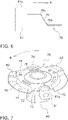
- FIG. 7 is Modification A of the basic embodiment.
- a configuration of Modification A is different from the configuration of the basic embodiment illustrated in FIG. 4 in that the first fixed leg 61, the second fixed leg 62, and the third fixed leg 63 do not protrude above the oil separation member 70. Therefore, upper surfaces of the first fixed leg 61, the second fixed leg 62, and the third fixed leg 63 (for example, the first fixed leg upper surface 61a) and the second horizontal surface 73 are located at substantially the same height.
- This configuration also prevents the swirling flow of the refrigerant in the lower space S3 from colliding with the first fixed leg 61, the second fixed leg 62, and the third fixed leg 63.
- the lower frame 60 has three fixed legs.
- the number of fixed legs included in the lower frame 60 may be a number other than 3, such as 2, 4, 5, or 6.
- Patent Literature 1 JP 2015-105637 A
Landscapes
- Engineering & Computer Science (AREA)
- Mechanical Engineering (AREA)
- General Engineering & Computer Science (AREA)
- Applications Or Details Of Rotary Compressors (AREA)
- Rotary Pumps (AREA)
Abstract
Description
- The present disclosure relates to a scroll compressor including an oil separation member that separates refrigerant from oil.
- A scroll compressor disclosed in Patent Literature 1 (
JP 2015-105637 A - A refrigerant discharged from a compression mechanism contains the lubricating oil. The refrigerant then moves to near the lower bearing member. There, the refrigerant receives a force from a rotating rotor and swirls in a circumferential direction of the casing along the oil separation plate. As the refrigerant swirls, the lubricating oil is separated from the refrigerant by cyclone separation.
- The refrigerant swirling in the circumferential direction of the casing along the oil separation plate may contact the legs of the lower bearing member. At this time, swirling of the refrigerant is stopped, and separation of the lubricating oil from the refrigerant is inhibited. In this case, a phenomenon called "oil loss" occurs more significantly in which the refrigerant is discharged to outside of the scroll compressor while containing the lubricating oil. As a result, an amount of the lubricating oil in the scroll compressor may be insufficient.
- A scroll compressor according to a first aspect includes a casing, a scroll compression mechanism, a motor, a crankshaft, a bearing, a frame, and an oil separation member. The scroll compression mechanism is disposed in the casing. The motor is disposed in the casing and below the scroll compression mechanism. The motor includes a stator and a rotor. The rotor rotates in a rotational direction. The crankshaft connects the scroll compression mechanism and the motor. The bearing is disposed below the motor. The bearing rotatably supports the crankshaft. The frame is fixed to the casing. The frame supports the bearing. The oil separation member is fixed to the frame. The oil separation member suppresses mixing of a refrigerant and a lubricating oil in the casing. The frame includes a first fixed leg and a second fixed leg which are fixed to the casing. The oil separation member has a first horizontal surface and a first inclined surface. The first inclined surface has a first inclined surface upstream portion and a first inclined surface downstream portion in a rotational direction. The first inclined surface downstream portion is disposed higher than the first inclined surface upstream portion. The first horizontal surface, the first inclined surface, and the first fixed leg are disposed in that order from upstream to downstream in the rotational direction.
- In this configuration, a swirling flow of the refrigerant advances obliquely upward by the first inclined surface, and then approaches the first fixed leg. Therefore, the swirling flow of the refrigerant is prevented from colliding with first fixed leg.
- A scroll compressor according to a second aspect is the scroll compressor according to the first aspect, in which the oil separation member further has a second horizontal surface. The first horizontal surface, the first inclined surface, the second horizontal surface, and the first fixed leg are disposed in that order from upstream to downstream in the rotational direction.
- In this configuration, the oil separation member has the second horizontal surface. Therefore, the oil separation member can be easily manufactured as compared with a case where an inclined surface is formed at a place where the second horizontal surface is to be provided.
- A scroll compressor according to a third aspect is the scroll compressor according to the second aspect, the scroll compressor further including an oil return passage. The oil return passage guides the lubricating oil from above the motor to below the motor. The oil separation member further has a third horizontal surface. The third horizontal surface includes an oil return passage portion. The oil return passage portion is located immediately below the oil return passage. The third horizontal surface and the second fixed leg are disposed in that order from upstream to downstream in the rotational direction.
- In this configuration, a refrigerant flow swirling along the third horizontal surface collides with the second fixed leg. Therefore, since the lubricating oil falling into the oil return passage portion is blocked by the second fixed leg, the lubricating oil falls into an oil reservoir.
- A scroll compressor according to a fourth aspect is the scroll compressor according to the third aspect, in which the stator further includes a core cut. The core cut is located on an outer periphery of the stator. The oil return passage includes the core cut.
- In this configuration, the oil return passage includes the core cut. Therefore, a dedicated member constituting the oil return passage is not required at a height of the motor.
- A scroll compressor according to a fifth aspect is the scroll compressor according to the fourth aspect, in which the first inclined surface upstream portion and the first inclined surface downstream portion are separated from each other by a first height difference H1. The first inclined surface upstream portion and the first inclined surface downstream portion are separated from each other in a circumferential direction by a first circumferential distance L1. The first fixed leg has a first fixed leg upper surface. The second horizontal surface and the first fixed leg upper surface are separated from each other by a second height difference H2. The second horizontal surface extends in the circumferential direction by a second circumferential distance L2. A first inclination H1/L1 which is a ratio of the first height difference H1 to the first circumferential distance L1 is larger than a second inclination H2/L2 which is a ratio of the second height difference H2 to the second circumferential distance L2.
- In this configuration, the first inclination is larger than the second inclination. Therefore, since an advancing direction of the refrigerant flow is set obliquely upward by the first inclined surface, the refrigerant flow can be prevented from colliding with the first fixed leg.
- A scroll compressor according to a sixth aspect is the scroll compressor according to the fifth aspect, in which the first inclination H1/L1 is 0.5 or more and 2.0 or less.
- This configuration designates a range of the first inclination. It is therefore easy to manufacture the oil separation member.
- A scroll compressor according to a seventh aspect is the scroll compressor according to the fifth or sixth aspect, in which the second inclination H2/L2 is 0.3 or more and 1.0 or less.
- This configuration designates a range of the second inclination. It is therefore easy to manufacture the frame.
- A scroll compressor according to an eighth aspect is the scroll compressor according to any one of the first to seventh aspects, in which the oil separation member further has a second inclined surface. The second inclined surface has a second inclined surface upstream portion and a second inclined surface downstream portion in the rotational direction. The second inclined surface downstream portion is disposed lower than the second inclined surface upstream portion. The first fixed leg and the second inclined surface are disposed in that order from upstream to downstream in the rotational direction.
- In this configuration, the second inclined surface having an inclination opposite to an inclination of the first inclined surface is provided downstream of the first fixed leg. Therefore, a structure of the oil separation member can be simplified.
- A scroll compressor according to a ninth aspect is the scroll compressor according to any one of the first to eighth aspects, in which the oil separation member further has a third inclined surface. The third inclined surface is inclined in a cross section in a radial direction of the oil separation member. The third inclined surface is high on an inner side in the radial direction and low on an outer side in the radial direction.
- In this configuration, the oil separation member has the third inclined surface which is an inclination in the radial direction. Therefore, a level difference formed by the first horizontal surface and the second horizontal surface is absorbed by the third inclined surface.
-
-
FIG. 1 is a sectional view of ascroll compressor 10 according to a basic embodiment. -
FIG. 2 is a side view of some components of thescroll compressor 10. -
FIG. 3 is a side view of some components of thescroll compressor 10. -
FIG. 4 is a perspective view of alower frame 60 and anoil separation member 70. -
FIG. 5 is a schematic diagram of theoil separation member 70 as viewed from an outer periphery. -
FIG. 6 is a schematic diagram of theoil separation member 70 as viewed from the outer periphery. -
FIG. 7 is a perspective view of alower frame 60 and anoil separation member 70 according to a modification. -
FIG. 1 is a sectional view of ascroll compressor 10 according to a basic embodiment. Thescroll compressor 10 compresses a low-pressure refrigerant as a fluid to generate a high-pressure refrigerant. Thescroll compressor 10 includes acasing 11, amotor 20, acrankshaft 30, ascroll compression mechanism 40, anupper frame 50, alower frame 60, anoil separation member 70, an oil guide 51 (FIG. 2 ), and a refrigerant guide 52 (FIG. 3 ). - As illustrated in
FIG. 1 , thecasing 11 accommodates various components of thescroll compressor 10. Thecasing 11 includes abarrel 11a, anupper portion 11b, and alower portion 11c. Thebarrel 11a has a substantially cylindrical shape. Theupper portion 11b and thelower portion 11c are airtightly joined to thebarrel 11a. Theupper portion 11b is provided with asuction pipe 15. Thebarrel 11a is provided with adischarge pipe 16. Anoil reservoir 12 that stores lubricating oil is provided near thelower portion 11c. - The
motor 20 generates power for driving thescroll compression mechanism 40. Themotor 20 is disposed in thecasing 11. Themotor 20 is disposed below thescroll compression mechanism 40. Themotor 20 includes astator 21 and arotor 22. - The
stator 21 includes coils (not illustrated). The coils convert power received by thescroll compressor 10 into magnetic force. Thestator 21 has a substantially cylindrical shape. Thestator 21 is fixed to thebarrel 11a. Thestator 21 has on its outer periphery a notch called acore cut 21a. A gap formed by the core cut 21a between thebarrel 11a and thestator 21 functions as a passage for the refrigerant. - The
rotor 22 is disposed near thestator 21. Therotor 22 includes a permanent magnet (not illustrated). Therotor 22 has a substantially cylindrical shape. The coils of thestator 21 and the permanent magnet of therotor 22 interact with each other to rotate therotor 22. - The
crankshaft 30 transmits power generated by themotor 20 to thescroll compression mechanism 40. Thecrankshaft 30 connects thescroll compression mechanism 40 and themotor 20. Thecrankshaft 30 is fixed to therotor 22. Thecrankshaft 30 has aconcentric portion 31 and aneccentric portion 32. Theconcentric portion 31 is concentric with an axis of therotor 22 and thecrankshaft 30. Theeccentric portion 32 is eccentric from the axis. Theconcentric portion 31 is rotatably supported by anupper bearing 35 and alower bearing 36. Theeccentric portion 32 is rotatably supported by aneccentric bearing 37. Theupper bearing 35 is disposed above themotor 20. Thelower bearing 36 is disposed below themotor 20. Theeccentric bearing 37 is disposed near thescroll compression mechanism 40. - An
oil ascending hole 33 is provided inside thecrankshaft 30. As thecrankshaft 30 rotates, the lubricating oil in theoil reservoir 12 is sucked up into theoil ascending hole 33 and then supplied to thescroll compression mechanism 40, theupper bearing 35, thelower bearing 36, and theeccentric bearing 37. - The
scroll compression mechanism 40 is disposed in thecasing 11. Thescroll compression mechanism 40 includes a fixedscroll 41 and amovable scroll 42. - The fixed
scroll 41 includes a fixedplate 41a and a fixed wrap 41b. The fixedplate 41a is a part extending in a horizontal direction. The fixed wrap 41b extends in a vertical direction from the fixedplate 41a. The fixed wrap 41b has a spiral shape in plan view. Adischarge hole 45 for discharging a high-pressure refrigerant is formed at a center of the fixedplate 41a. - The
movable scroll 42 includes amovable plate 42a, amovable wrap 42b, and amovable protrusion 42c. Themovable plate 42a is a part extending in the horizontal direction. Themovable wrap 42b extends in the vertical direction from themovable plate 42a. Themovable wrap 42b has a spiral shape in plan view. Themovable protrusion 42c extends in the vertical direction from themovable plate 42a. Themovable protrusion 42c has a concave portion. The concave portion accommodates theeccentric bearing 37 and theeccentric portion 32. Themovable scroll 42 can revolve around the fixedscroll 41. - The fixed
scroll 41 and themovable scroll 42 together define a plurality ofcompression chambers 43. Thecompression chamber 43 at an outermost position communicates with thesuction pipe 15. - The
upper frame 50 supports theupper bearing 35. Theupper frame 50 supports thecrankshaft 30 via theupper bearing 35. Theupper frame 50 is fixed to thebarrel 11a of thecasing 11. The fixedscroll 41 is fixed to theupper frame 50. Theupper frame 50 is provided with arefrigerant passage 50a vertically penetrating theupper frame 50. - The
lower frame 60 supports thelower bearing 36. Thelower frame 60 supports thecrankshaft 30 via thelower bearing 36. Thelower frame 60 is fixed to thebarrel 11a of thecasing 11. - The
oil separation member 70 suppresses mixing of the refrigerant and the lubricating oil. That is, theoil separation member 70 suppresses scattering of the lubricating oil that may be caused by the gas refrigerant contacting theoil reservoir 12, and thus suppresses mixing of the refrigerant and the lubricating oil. Theoil separation member 70 is fixed to thelower frame 60. -
FIG. 2 is a side view of some components of thescroll compressor 10. Theoil guide 51 is provided on thebarrel 11a of thecasing 11. Theoil guide 51 is provided with agroove 51a. Thegroove 51a guides the lubricating oil located above downward. Thegroove 51a of theoil guide 51 and the core cut 21a of thestator 21 constitute an oil return passage P. The oil return passage P guides the lubricating oil from above themotor 20 to below themotor 20. The lubricating oil located above theoil guide 51 passes through the oil return passage P and then falls to an oilreturn passage portion 79 of theoil separation member 70. The oilreturn passage portion 79 is located immediately below the oil return passage P. -
FIG. 3 is a side view of some components of thescroll compressor 10. Therefrigerant guide 52 is provided on thebarrel 11a of thecasing 11. Therefrigerant guide 52 guides the refrigerant located above in a circumferential direction and downward. As a result, part of the refrigerant swirls along an inner peripheral surface of thebarrel 11a while advancing in the horizontal direction. Another part of the refrigerant advances downward and passes through thecore cut 21a. - Movements of the refrigerant and the lubricating oil will be described below. It should be noted that the refrigerant and the lubricating oil do not move completely independently of each other. The refrigerant and the lubricating oil exhibit compatibility. Thus, the movement of the refrigerant or the lubricating oil discussed below may also be movement of a mixture of the refrigerant and lubricating oil.
- The low-pressure refrigerant enters the
scroll compressor 10 from thesuction pipe 15 illustrated inFIG. 1 . The low-pressure refrigerant then enters thecompression chamber 43 at the outermost position of thescroll compression mechanism 40. When the rotation of thecrankshaft 30 revolves themovable scroll 42, thecompression chamber 43 moves to a center of thescroll compression mechanism 40 while reducing the volume. In this process, the low-pressure refrigerant is compressed to become a high-pressure refrigerant. The high-pressure refrigerant exits from thedischarge hole 45 to an upper space S1. Thereafter, the high-pressure refrigerant reaches a middle space S2 by passing through therefrigerant passage 50a of theupper frame 50. The high-pressure refrigerant then reaches therefrigerant guide 52. - The
refrigerant guide 52 allows part of the refrigerant to swirl along an inner periphery of thebarrel 11a while advancing in the horizontal direction. This swirling flow may be further accelerated by the rotation of therotor 22. Another part of the refrigerant advances downward, passes through the core cut 21a, and collides with theoil separation member 70. Next, in a lower space S3 between themotor 20 and thelower frame 60, the rotation of therotor 22 swirls the refrigerant. - The lubricating oil is sucked up from the
oil reservoir 12 to theoil ascending hole 33. Thereafter, the lubricating oil is supplied to thescroll compression mechanism 40, theupper bearing 35, thelower bearing 36, and theeccentric bearing 37. Subsequently, the lubricating oil exits thescroll compression mechanism 40, theupper bearing 35, thelower bearing 36, and theeccentric bearing 37. Next, the lubricating oil moves downward along the inner peripheral surface of thebarrel 11a or the oil return passage P of theoil guide 51. The lubricating oil having exited the oil return passage P falls from the core cut 21a to the oilreturn passage portion 79 of theoil separation member 70. -
FIG. 4 is a perspective view of thelower frame 60 and theoil separation member 70. An arrow in the drawing indicates a rotational direction R of therotor 22. - The
lower frame 60 includes a firstfixed leg 61, a secondfixed leg 62, and a thirdfixed leg 63. The firstfixed leg 61, the secondfixed leg 62, and the thirdfixed leg 63 are all fixed to thebarrel 11a of thecasing 11. A method of fixing is, for example, welding. The firstfixed leg 61 has a first fixed legupper surface 61a. - The
oil separation member 70 is a plate-shaped member fixed to thelower frame 60. A firsthorizontal surface 71, a secondhorizontal surface 73, a thirdhorizontal surface 74, a fourthhorizontal surface 81, a fifthhorizontal surface 83, a sixthhorizontal surface 84, a seventhhorizontal surface 86, an eighthhorizontal surface 88, a firstinclined surface 72, a secondinclined surface 75, a thirdinclined surface 82, a fourthinclined surface 85, a fifthinclined surface 87, and anotch 76 are formed at a position close to an outer periphery of theoil separation member 70. Thenotch 76 allows the lubricating oil accumulated on theoil separation member 70 to fall into theoil reservoir 12. - The first
horizontal surface 71, the firstinclined surface 72, the secondhorizontal surface 73, the firstfixed leg 61, and the secondinclined surface 75 are disposed in that order from upstream to downstream in the rotational direction R. The thirdhorizontal surface 74 and the secondfixed leg 62 are disposed in that order from upstream to downstream in the rotational direction R. -
FIG. 5 is a schematic diagram of a periphery of the firstinclined surface 72. An upstream side of the firstinclined surface 72 is a first inclined surface upstream portion 72a. A downstream side of the firstinclined surface 72 is a first inclined surfacedownstream portion 72b. The first inclined surfacedownstream portion 72b is disposed higher than the first inclined surface upstream portion 72a. - The first inclined surface upstream portion 72a and the first inclined surface
downstream portion 72b are separated from each other by a first height difference H1. The first inclined surface upstream portion 72a and the first inclined surfacedownstream portion 72b are separated from each other in the circumferential direction by a first circumferential distance L1. The secondhorizontal surface 73 and the first fixed legupper surface 61a are separated from each other by a second height difference H2. The secondhorizontal surface 73 extends in the circumferential direction by a second circumferential distance L2. - A ratio of the first height difference H1 to the first circumferential distance L1 is a first inclination H1/L1. A ratio of the second height difference H2 to the second circumferential distance L2 is a second inclination H2/L2. The first inclination H1/L1 is larger than the second inclination H2/L2. The first inclination H1/L1 is 0.5 or more and 2.0 or less. The second inclination H2/L2 is 0.3 or more and 1.0 or less.
-
FIG. 6 is a schematic diagram of a periphery of the secondinclined surface 75. An upstream side of the secondinclined surface 75 is a second inclined surfaceupstream portion 75a. A downstream side of the secondinclined surface 75 is a second inclined surfacedownstream portion 75b. The second inclined surfacedownstream portion 75b is disposed lower than the second inclined surfaceupstream portion 75a. - Returning to
FIG. 4 , a thirdinclined surface 78 is formed on theoil separation member 70. The thirdinclined surface 78 is inclined in a cross section in a radial direction of theoil separation member 70. The thirdinclined surface 78 is high on an inner side in the radial direction and low on an outer side in the radial direction. - The circumferential distance L2 of the second
horizontal surface 73 is set to be larger than the circumferential distance of the fifthhorizontal surface 83. This is because the firsthorizontal surface 71 located upstream of the secondhorizontal surface 73 is located below therefrigerant guide 52. The firsthorizontal surface 71 receives a strong refrigerant flow blown downward from therefrigerant guide 52. - (5-1)
- The swirling flow of the refrigerant in the lower space S3 advances obliquely upward by the first
inclined surface 72, and then approaches the firstfixed leg 61. Therefore, the swirling flow of the refrigerant is prevented from colliding with the firstfixed leg 61. As a result, since cyclone separation of the swirling flow is less likely to be inhibited, the lubricating oil contained in the refrigerant is likely to be separated from the refrigerant. The separated lubricating oil can return to theoil reservoir 12. - (5-2)
- The
oil separation member 70 has the thirdhorizontal surface 74. Therefore, theoil separation member 70 can be more easily manufactured than in a case where an inclined surface is formed at a place where the thirdhorizontal surface 74 is to be provided. - (5-3)
- The refrigerant swirling along the third
horizontal surface 74 in the lower space S3 collides with the secondfixed leg 62. Therefore, since the lubricating oil falling into the oilreturn passage portion 79 is blocked by the secondfixed leg 62, the lubricating oil passes through thenotch 76 and appropriately falls into theoil reservoir 12. - (5-4)
- The oil return passage P includes the
core cut 21a. Therefore, a dedicated member constituting the oil return passage P is not required at a height of themotor 20. - (5-5)
- The first inclination H1/L1 is larger than the second inclination H2/L2. Therefore, since an advancing direction of the refrigerant flow is set obliquely upward by the first
inclined surface 72, the refrigerant flow can be prevented from colliding with the firstfixed leg 61. - (5-6)
- The second
inclined surface 75 having an inclination opposite to an inclination of the firstinclined surface 72 is provided downstream of the firstfixed leg 61. Therefore, a structure of theoil separation member 70 can be simplified. - (5-7)
- The
oil separation member 70 has the thirdinclined surface 78 which is an inclination in the radial direction. Therefore, a level difference formed by the firsthorizontal surface 71 and the secondhorizontal surface 73 is absorbed by the thirdinclined surface 78. - The following are modifications of the basic embodiment. For example, a plurality of modifications may be combined.
-
FIG. 7 is Modification A of the basic embodiment. A configuration of Modification A is different from the configuration of the basic embodiment illustrated inFIG. 4 in that the firstfixed leg 61, the secondfixed leg 62, and the thirdfixed leg 63 do not protrude above theoil separation member 70. Therefore, upper surfaces of the firstfixed leg 61, the secondfixed leg 62, and the third fixed leg 63 (for example, the first fixed legupper surface 61a) and the secondhorizontal surface 73 are located at substantially the same height. - This configuration also prevents the swirling flow of the refrigerant in the lower space S3 from colliding with the first
fixed leg 61, the secondfixed leg 62, and the thirdfixed leg 63. - In the basic embodiment, the
lower frame 60 has three fixed legs. Alternatively, the number of fixed legs included in thelower frame 60 may be a number other than 3, such as 2, 4, 5, or 6. - The embodiment of the present disclosure has been described above, but it will be understood that various changes to forms and details can be made without departing from the gist and scope of the present disclosure as set forth in the claims.
-
- 10: scroll compressor
- 11: casing
- 20: motor
- 21: stator
- 21a: core cut
- 22: rotor
- 30: crankshaft
- 35: upper bearing
- 36: lower bearing (bearing)
- 37: eccentric bearing
- 40: scroll compression mechanism
- 50: upper frame
- 51: oil guide
- 51a: groove
- 52: refrigerant guide
- 60: lower frame (frame)
- 61: first fixed leg
- 61a: first fixed leg upper surface
- 62: second fixed leg
- 63: third fixed leg
- 70: oil separation member
- 71: first horizontal surface
- 72: first inclined surface
- 72a: first inclined surface upstream portion
- 72b: first inclined surface downstream portion
- 73: second horizontal surface
- 74: third horizontal surface
- 75: second inclined surface
- 75a: second inclined surface upstream portion
- 75b: second inclined surface downstream portion
- 78: third inclined surface
- 79: oil return passage portion
- H1: first height difference
- H2: second height difference
- H1/L1: first inclination
- H2/L2: second inclination
- L1: first circumferential distance
- L2: second circumferential distance
- P: oil return passage
- R: rotational direction
- Patent Literature 1:
JP 2015-105637 A
Claims (9)
- A scroll compressor (10) comprising:a casing (11);a scroll compression mechanism (40) disposed in the casing;a motor (20) disposed in the casing and below the scroll compression mechanism and including a stator (21) and a rotor (22) that rotates in a rotational direction (R);a crankshaft (30) that connects the scroll compression mechanism and the motor;a bearing (36) that is disposed below the motor and rotatably supports the crankshaft;a frame (60) that is fixed to the casing and supports the bearing; andan oil separation member (70) that is fixed to the frame and suppresses mixing of a refrigerant and a lubricating oil in the casing, whereinthe frame has a first fixed leg (61) and a second fixed leg (62) that are fixed to the casing,the oil separation member has a first horizontal surface (71) and a first inclined surface(72), the first inclined surface has a first inclined surface upstream portion (72a) and a first inclined surface downstream portion (72b) in the rotational direction,the first inclined surface downstream portion is disposed higher than the first inclined surface upstream portion, andthe first horizontal surface, the first inclined surface, and the first fixed leg are disposed in an order of the first horizontal surface, the first inclined surface, and the first fixed leg from upstream to downstream in the rotational direction.
- The scroll compressor according to claim 1, whereinthe oil separation member further has a second horizontal surface (73), andthe first horizontal surface, the first inclined surface, the second horizontal surface, and the first fixed leg are disposed in an order of the first horizontal surface, the first inclined surface, the second horizontal surface, and the first fixed leg from upstream to downstream in the rotational direction.
- The scroll compressor according to claim 2, further comprising an oil return passage (P) that guides the lubricating oil from above the motor to below the motor, whereinthe oil separation member further has a third horizontal surface (74),the third horizontal surface includes an oil return passage portion (79),the oil return passage portion is located immediately below the oil return passage, andthe third horizontal surface and the second fixed leg are disposed in an order of the third horizontal surface and the second fixed leg from upstream to downstream in the rotational direction.
- The scroll compressor according to claim 3, wherein
the stator includes a core cut (21a) located on an outer periphery of the stator, and the oil return passage includes the core cut. - The scroll compressor according to claim 4, whereinthe first inclined surface upstream portion and the first inclined surface downstream portion are separated from each other by a first height difference HI,the first inclined surface upstream portion and the first inclined surface downstream portion are separated from each other by a first circumferential distance L1 in a circumferential direction,the first fixed leg has a first fixed leg upper surface (61a),the second horizontal surface and the first fixed leg upper surface are separated from each other by a second height difference H2,the second horizontal surface extends in the circumferential direction by a second circumferential distance L2, anda first inclination H1/L1 that is a ratio of the first height difference H1 to the first circumferential distance L1 is larger than a second inclination H2/L2 that is a ratio of the second height difference H2 to the second circumferential distance L2.
- The scroll compressor according to claim 5, wherein
the first inclination H1/L1 is 0.5 or more and 2.0 or less. - The scroll compressor according to claim 5 or 6, wherein
the second inclination H2/L2 is 0.3 or more and 1.0 or less. - The scroll compressor according to any one of claims 1 to 7, whereinthe oil separation member further has a second inclined surface (75),the second inclined surface has a second inclined surface upstream portion (75a) and a second inclined surface downstream portion (75b) in the rotational direction,the second inclined surface downstream portion is disposed lower than the second inclined surface upstream portion, andthe first fixed leg and the second inclined surface are disposed in an order of the first fixed leg and the second inclined surface from upstream to downstream in the rotational direction.
- The scroll compressor according to any one of claims 1 to 8, whereinthe oil separation member further has a third inclined surface (78),the third inclined surface is inclined in a cross section in a radial direction of the oil separation member, andthe third inclined surface is high on an inner side in the radial direction and low on an outer side in the radial direction.
Applications Claiming Priority (2)
| Application Number | Priority Date | Filing Date | Title |
|---|---|---|---|
| JP2020015238A JP6879395B1 (en) | 2020-01-31 | 2020-01-31 | Scroll compressor with oil separator |
| PCT/JP2021/002573 WO2021153541A1 (en) | 2020-01-31 | 2021-01-26 | Scroll compressor comprising oil separation member |
Publications (3)
| Publication Number | Publication Date |
|---|---|
| EP4083429A1 true EP4083429A1 (en) | 2022-11-02 |
| EP4083429A4 EP4083429A4 (en) | 2023-05-24 |
| EP4083429B1 EP4083429B1 (en) | 2024-05-29 |
Family
ID=76083806
Family Applications (1)
| Application Number | Title | Priority Date | Filing Date |
|---|---|---|---|
| EP21747932.8A Active EP4083429B1 (en) | 2020-01-31 | 2021-01-26 | Scroll compressor comprising oil separation member |
Country Status (6)
| Country | Link |
|---|---|
| US (1) | US11674515B2 (en) |
| EP (1) | EP4083429B1 (en) |
| JP (1) | JP6879395B1 (en) |
| CN (1) | CN114829778B (en) |
| ES (1) | ES2992832T3 (en) |
| WO (1) | WO2021153541A1 (en) |
Families Citing this family (1)
| Publication number | Priority date | Publication date | Assignee | Title |
|---|---|---|---|---|
| JP7518394B2 (en) * | 2021-11-01 | 2024-07-18 | ダイキン工業株式会社 | Compressors and refrigeration equipment |
Family Cites Families (12)
| Publication number | Priority date | Publication date | Assignee | Title |
|---|---|---|---|---|
| JPS60166784A (en) * | 1984-02-10 | 1985-08-30 | Mitsubishi Electric Corp | Scroll type compressor |
| JPH0347496A (en) | 1989-07-12 | 1991-02-28 | Mitsubishi Electric Corp | Scroll compressor |
| JP2681838B2 (en) | 1990-07-13 | 1997-11-26 | 松下電器産業株式会社 | TV receiver |
| JP5444880B2 (en) * | 2009-06-25 | 2014-03-19 | ダイキン工業株式会社 | Compressor |
| JP2012202253A (en) * | 2011-03-24 | 2012-10-22 | Sanyo Electric Co Ltd | Scroll compression device |
| JP5914805B2 (en) * | 2011-08-29 | 2016-05-11 | パナソニックIpマネジメント株式会社 | Scroll compressor |
| CN202441599U (en) * | 2012-02-29 | 2012-09-19 | 珠海格力节能环保制冷技术研究中心有限公司 | Scroll compressor |
| JP2015105637A (en) | 2013-12-02 | 2015-06-08 | ダイキン工業株式会社 | Compressor |
| JP2015105638A (en) * | 2013-12-02 | 2015-06-08 | ダイキン工業株式会社 | Compressor |
| CZ307894B6 (en) * | 2014-11-25 | 2019-07-31 | Mitsubishi Electric Corporation | Compressor |
| WO2017072867A1 (en) * | 2015-10-27 | 2017-05-04 | 三菱電機株式会社 | Rotary compressor |
| JP2017210898A (en) * | 2016-05-24 | 2017-11-30 | ダイキン工業株式会社 | Scroll compressor |
-
2020
- 2020-01-31 JP JP2020015238A patent/JP6879395B1/en active Active
-
2021
- 2021-01-26 CN CN202180007348.1A patent/CN114829778B/en active Active
- 2021-01-26 WO PCT/JP2021/002573 patent/WO2021153541A1/en not_active Ceased
- 2021-01-26 EP EP21747932.8A patent/EP4083429B1/en active Active
- 2021-01-26 ES ES21747932T patent/ES2992832T3/en active Active
-
2022
- 2022-06-21 US US17/845,574 patent/US11674515B2/en active Active
Also Published As
| Publication number | Publication date |
|---|---|
| CN114829778B (en) | 2023-06-23 |
| WO2021153541A1 (en) | 2021-08-05 |
| CN114829778A (en) | 2022-07-29 |
| EP4083429A4 (en) | 2023-05-24 |
| JP2021124013A (en) | 2021-08-30 |
| ES2992832T3 (en) | 2024-12-18 |
| EP4083429B1 (en) | 2024-05-29 |
| US11674515B2 (en) | 2023-06-13 |
| US20220316479A1 (en) | 2022-10-06 |
| JP6879395B1 (en) | 2021-06-02 |
Similar Documents
| Publication | Publication Date | Title |
|---|---|---|
| US11053938B2 (en) | Scroll compressor with oil separator | |
| US20180328364A1 (en) | Scroll compressor | |
| JP6493507B2 (en) | Compressor | |
| EP2927498B1 (en) | Scroll compressor | |
| JP5427892B2 (en) | Multistage compressor | |
| US11187230B2 (en) | Scroll compressor | |
| KR102373829B1 (en) | A compressor | |
| EP2309132A1 (en) | Horizontal scroll compressor | |
| US9714656B2 (en) | Rotary machine and compressor | |
| EP4083429B1 (en) | Scroll compressor comprising oil separation member | |
| CN113279963B (en) | Scroll compressor having a rotor with a rotor shaft having a rotor shaft with a | |
| EP2466140A1 (en) | Compressor | |
| JP2013024129A (en) | Compressor | |
| CN214533520U (en) | scroll compressor | |
| JP2020045778A (en) | Compressor | |
| JP2000161268A (en) | Scroll compressor | |
| JP7838506B2 (en) | compressor | |
| EP4729782A1 (en) | Compressor and refrigeration device | |
| WO2023074214A1 (en) | Compressor and freezer device | |
| US20260117773A1 (en) | Compressor and refrigeration apparatus | |
| WO2013069287A1 (en) | Compressor | |
| JP5690638B2 (en) | Horizontal scroll compressor | |
| JP2019019790A (en) | Compressor | |
| WO2023090148A1 (en) | Compressor | |
| JPWO2019097708A1 (en) | Scroll compressor |
Legal Events
| Date | Code | Title | Description |
|---|---|---|---|
| STAA | Information on the status of an ep patent application or granted ep patent |
Free format text: STATUS: THE INTERNATIONAL PUBLICATION HAS BEEN MADE |
|
| PUAI | Public reference made under article 153(3) epc to a published international application that has entered the european phase |
Free format text: ORIGINAL CODE: 0009012 |
|
| STAA | Information on the status of an ep patent application or granted ep patent |
Free format text: STATUS: REQUEST FOR EXAMINATION WAS MADE |
|
| 17P | Request for examination filed |
Effective date: 20220726 |
|
| AK | Designated contracting states |
Kind code of ref document: A1 Designated state(s): AL AT BE BG CH CY CZ DE DK EE ES FI FR GB GR HR HU IE IS IT LI LT LU LV MC MK MT NL NO PL PT RO RS SE SI SK SM TR |
|
| RAP3 | Party data changed (applicant data changed or rights of an application transferred) |
Owner name: DAIKIN INDUSTRIES, LTD. |
|
| DAV | Request for validation of the european patent (deleted) | ||
| DAX | Request for extension of the european patent (deleted) | ||
| A4 | Supplementary search report drawn up and despatched |
Effective date: 20230424 |
|
| RIC1 | Information provided on ipc code assigned before grant |
Ipc: F04C 23/00 20060101ALI20230418BHEP Ipc: F04C 18/02 20060101ALI20230418BHEP Ipc: F04C 29/02 20060101AFI20230418BHEP |
|
| P01 | Opt-out of the competence of the unified patent court (upc) registered |
Effective date: 20230525 |
|
| RIC1 | Information provided on ipc code assigned before grant |
Ipc: F04C 23/00 20060101ALI20231110BHEP Ipc: F04C 18/02 20060101ALI20231110BHEP Ipc: F04C 29/02 20060101AFI20231110BHEP |
|
| GRAP | Despatch of communication of intention to grant a patent |
Free format text: ORIGINAL CODE: EPIDOSNIGR1 |
|
| STAA | Information on the status of an ep patent application or granted ep patent |
Free format text: STATUS: GRANT OF PATENT IS INTENDED |
|
| INTG | Intention to grant announced |
Effective date: 20240117 |
|
| GRAS | Grant fee paid |
Free format text: ORIGINAL CODE: EPIDOSNIGR3 |
|
| GRAA | (expected) grant |
Free format text: ORIGINAL CODE: 0009210 |
|
| STAA | Information on the status of an ep patent application or granted ep patent |
Free format text: STATUS: THE PATENT HAS BEEN GRANTED |
|
| AK | Designated contracting states |
Kind code of ref document: B1 Designated state(s): AL AT BE BG CH CY CZ DE DK EE ES FI FR GB GR HR HU IE IS IT LI LT LU LV MC MK MT NL NO PL PT RO RS SE SI SK SM TR |
|
| REG | Reference to a national code |
Ref country code: CH Ref legal event code: EP |
|
| REG | Reference to a national code |
Ref country code: IE Ref legal event code: FG4D |
|
| REG | Reference to a national code |
Ref country code: DE Ref legal event code: R096 Ref document number: 602021013893 Country of ref document: DE |
|
| REG | Reference to a national code |
Ref country code: LT Ref legal event code: MG9D |
|
| REG | Reference to a national code |
Ref country code: NL Ref legal event code: MP Effective date: 20240529 |
|
| PG25 | Lapsed in a contracting state [announced via postgrant information from national office to epo] |
Ref country code: IS Free format text: LAPSE BECAUSE OF FAILURE TO SUBMIT A TRANSLATION OF THE DESCRIPTION OR TO PAY THE FEE WITHIN THE PRESCRIBED TIME-LIMIT Effective date: 20240929 |
|
| PG25 | Lapsed in a contracting state [announced via postgrant information from national office to epo] |
Ref country code: BG Free format text: LAPSE BECAUSE OF FAILURE TO SUBMIT A TRANSLATION OF THE DESCRIPTION OR TO PAY THE FEE WITHIN THE PRESCRIBED TIME-LIMIT Effective date: 20240529 |
|
| PG25 | Lapsed in a contracting state [announced via postgrant information from national office to epo] |
Ref country code: HR Free format text: LAPSE BECAUSE OF FAILURE TO SUBMIT A TRANSLATION OF THE DESCRIPTION OR TO PAY THE FEE WITHIN THE PRESCRIBED TIME-LIMIT Effective date: 20240529 Ref country code: FI Free format text: LAPSE BECAUSE OF FAILURE TO SUBMIT A TRANSLATION OF THE DESCRIPTION OR TO PAY THE FEE WITHIN THE PRESCRIBED TIME-LIMIT Effective date: 20240529 |
|
| PG25 | Lapsed in a contracting state [announced via postgrant information from national office to epo] |
Ref country code: GR Free format text: LAPSE BECAUSE OF FAILURE TO SUBMIT A TRANSLATION OF THE DESCRIPTION OR TO PAY THE FEE WITHIN THE PRESCRIBED TIME-LIMIT Effective date: 20240830 |
|
| REG | Reference to a national code |
Ref country code: AT Ref legal event code: MK05 Ref document number: 1690865 Country of ref document: AT Kind code of ref document: T Effective date: 20240529 |
|
| PG25 | Lapsed in a contracting state [announced via postgrant information from national office to epo] |
Ref country code: AT Free format text: LAPSE BECAUSE OF FAILURE TO SUBMIT A TRANSLATION OF THE DESCRIPTION OR TO PAY THE FEE WITHIN THE PRESCRIBED TIME-LIMIT Effective date: 20240529 |
|
| PG25 | Lapsed in a contracting state [announced via postgrant information from national office to epo] |
Ref country code: PL Free format text: LAPSE BECAUSE OF FAILURE TO SUBMIT A TRANSLATION OF THE DESCRIPTION OR TO PAY THE FEE WITHIN THE PRESCRIBED TIME-LIMIT Effective date: 20240529 |
|
| PG25 | Lapsed in a contracting state [announced via postgrant information from national office to epo] |
Ref country code: LV Free format text: LAPSE BECAUSE OF FAILURE TO SUBMIT A TRANSLATION OF THE DESCRIPTION OR TO PAY THE FEE WITHIN THE PRESCRIBED TIME-LIMIT Effective date: 20240529 |
|
| PG25 | Lapsed in a contracting state [announced via postgrant information from national office to epo] |
Ref country code: PL Free format text: LAPSE BECAUSE OF FAILURE TO SUBMIT A TRANSLATION OF THE DESCRIPTION OR TO PAY THE FEE WITHIN THE PRESCRIBED TIME-LIMIT Effective date: 20240529 Ref country code: NO Free format text: LAPSE BECAUSE OF FAILURE TO SUBMIT A TRANSLATION OF THE DESCRIPTION OR TO PAY THE FEE WITHIN THE PRESCRIBED TIME-LIMIT Effective date: 20240829 Ref country code: LV Free format text: LAPSE BECAUSE OF FAILURE TO SUBMIT A TRANSLATION OF THE DESCRIPTION OR TO PAY THE FEE WITHIN THE PRESCRIBED TIME-LIMIT Effective date: 20240529 Ref country code: IS Free format text: LAPSE BECAUSE OF FAILURE TO SUBMIT A TRANSLATION OF THE DESCRIPTION OR TO PAY THE FEE WITHIN THE PRESCRIBED TIME-LIMIT Effective date: 20240929 Ref country code: HR Free format text: LAPSE BECAUSE OF FAILURE TO SUBMIT A TRANSLATION OF THE DESCRIPTION OR TO PAY THE FEE WITHIN THE PRESCRIBED TIME-LIMIT Effective date: 20240529 Ref country code: GR Free format text: LAPSE BECAUSE OF FAILURE TO SUBMIT A TRANSLATION OF THE DESCRIPTION OR TO PAY THE FEE WITHIN THE PRESCRIBED TIME-LIMIT Effective date: 20240830 Ref country code: FI Free format text: LAPSE BECAUSE OF FAILURE TO SUBMIT A TRANSLATION OF THE DESCRIPTION OR TO PAY THE FEE WITHIN THE PRESCRIBED TIME-LIMIT Effective date: 20240529 Ref country code: BG Free format text: LAPSE BECAUSE OF FAILURE TO SUBMIT A TRANSLATION OF THE DESCRIPTION OR TO PAY THE FEE WITHIN THE PRESCRIBED TIME-LIMIT Effective date: 20240529 Ref country code: AT Free format text: LAPSE BECAUSE OF FAILURE TO SUBMIT A TRANSLATION OF THE DESCRIPTION OR TO PAY THE FEE WITHIN THE PRESCRIBED TIME-LIMIT Effective date: 20240529 Ref country code: RS Free format text: LAPSE BECAUSE OF FAILURE TO SUBMIT A TRANSLATION OF THE DESCRIPTION OR TO PAY THE FEE WITHIN THE PRESCRIBED TIME-LIMIT Effective date: 20240829 |
|
| PG25 | Lapsed in a contracting state [announced via postgrant information from national office to epo] |
Ref country code: NL Free format text: LAPSE BECAUSE OF FAILURE TO SUBMIT A TRANSLATION OF THE DESCRIPTION OR TO PAY THE FEE WITHIN THE PRESCRIBED TIME-LIMIT Effective date: 20240529 |
|
| PG25 | Lapsed in a contracting state [announced via postgrant information from national office to epo] |
Ref country code: NL Free format text: LAPSE BECAUSE OF FAILURE TO SUBMIT A TRANSLATION OF THE DESCRIPTION OR TO PAY THE FEE WITHIN THE PRESCRIBED TIME-LIMIT Effective date: 20240529 |
|
| REG | Reference to a national code |
Ref country code: ES Ref legal event code: FG2A Ref document number: 2992832 Country of ref document: ES Kind code of ref document: T3 Effective date: 20241218 |
|
| PG25 | Lapsed in a contracting state [announced via postgrant information from national office to epo] |
Ref country code: DK Free format text: LAPSE BECAUSE OF FAILURE TO SUBMIT A TRANSLATION OF THE DESCRIPTION OR TO PAY THE FEE WITHIN THE PRESCRIBED TIME-LIMIT Effective date: 20240529 |
|
| PG25 | Lapsed in a contracting state [announced via postgrant information from national office to epo] |
Ref country code: EE Free format text: LAPSE BECAUSE OF FAILURE TO SUBMIT A TRANSLATION OF THE DESCRIPTION OR TO PAY THE FEE WITHIN THE PRESCRIBED TIME-LIMIT Effective date: 20240529 |
|
| PG25 | Lapsed in a contracting state [announced via postgrant information from national office to epo] |
Ref country code: CZ Free format text: LAPSE BECAUSE OF FAILURE TO SUBMIT A TRANSLATION OF THE DESCRIPTION OR TO PAY THE FEE WITHIN THE PRESCRIBED TIME-LIMIT Effective date: 20240529 |
|
| PG25 | Lapsed in a contracting state [announced via postgrant information from national office to epo] |
Ref country code: RO Free format text: LAPSE BECAUSE OF FAILURE TO SUBMIT A TRANSLATION OF THE DESCRIPTION OR TO PAY THE FEE WITHIN THE PRESCRIBED TIME-LIMIT Effective date: 20240529 Ref country code: SK Free format text: LAPSE BECAUSE OF FAILURE TO SUBMIT A TRANSLATION OF THE DESCRIPTION OR TO PAY THE FEE WITHIN THE PRESCRIBED TIME-LIMIT Effective date: 20240529 |
|
| PG25 | Lapsed in a contracting state [announced via postgrant information from national office to epo] |
Ref country code: SM Free format text: LAPSE BECAUSE OF FAILURE TO SUBMIT A TRANSLATION OF THE DESCRIPTION OR TO PAY THE FEE WITHIN THE PRESCRIBED TIME-LIMIT Effective date: 20240529 |
|
| PG25 | Lapsed in a contracting state [announced via postgrant information from national office to epo] |
Ref country code: SM Free format text: LAPSE BECAUSE OF FAILURE TO SUBMIT A TRANSLATION OF THE DESCRIPTION OR TO PAY THE FEE WITHIN THE PRESCRIBED TIME-LIMIT Effective date: 20240529 Ref country code: SK Free format text: LAPSE BECAUSE OF FAILURE TO SUBMIT A TRANSLATION OF THE DESCRIPTION OR TO PAY THE FEE WITHIN THE PRESCRIBED TIME-LIMIT Effective date: 20240529 Ref country code: RO Free format text: LAPSE BECAUSE OF FAILURE TO SUBMIT A TRANSLATION OF THE DESCRIPTION OR TO PAY THE FEE WITHIN THE PRESCRIBED TIME-LIMIT Effective date: 20240529 Ref country code: EE Free format text: LAPSE BECAUSE OF FAILURE TO SUBMIT A TRANSLATION OF THE DESCRIPTION OR TO PAY THE FEE WITHIN THE PRESCRIBED TIME-LIMIT Effective date: 20240529 Ref country code: DK Free format text: LAPSE BECAUSE OF FAILURE TO SUBMIT A TRANSLATION OF THE DESCRIPTION OR TO PAY THE FEE WITHIN THE PRESCRIBED TIME-LIMIT Effective date: 20240529 Ref country code: CZ Free format text: LAPSE BECAUSE OF FAILURE TO SUBMIT A TRANSLATION OF THE DESCRIPTION OR TO PAY THE FEE WITHIN THE PRESCRIBED TIME-LIMIT Effective date: 20240529 |
|
| REG | Reference to a national code |
Ref country code: DE Ref legal event code: R097 Ref document number: 602021013893 Country of ref document: DE |
|
| PLBE | No opposition filed within time limit |
Free format text: ORIGINAL CODE: 0009261 |
|
| STAA | Information on the status of an ep patent application or granted ep patent |
Free format text: STATUS: NO OPPOSITION FILED WITHIN TIME LIMIT |
|
| PG25 | Lapsed in a contracting state [announced via postgrant information from national office to epo] |
Ref country code: SI Free format text: LAPSE BECAUSE OF FAILURE TO SUBMIT A TRANSLATION OF THE DESCRIPTION OR TO PAY THE FEE WITHIN THE PRESCRIBED TIME-LIMIT Effective date: 20240529 |
|
| 26N | No opposition filed |
Effective date: 20250303 |
|
| REG | Reference to a national code |
Ref country code: CH Ref legal event code: PL |
|
| PG25 | Lapsed in a contracting state [announced via postgrant information from national office to epo] |
Ref country code: SE Free format text: LAPSE BECAUSE OF FAILURE TO SUBMIT A TRANSLATION OF THE DESCRIPTION OR TO PAY THE FEE WITHIN THE PRESCRIBED TIME-LIMIT Effective date: 20240529 |
|
| PG25 | Lapsed in a contracting state [announced via postgrant information from national office to epo] |
Ref country code: MC Free format text: LAPSE BECAUSE OF FAILURE TO SUBMIT A TRANSLATION OF THE DESCRIPTION OR TO PAY THE FEE WITHIN THE PRESCRIBED TIME-LIMIT Effective date: 20240529 Ref country code: LU Free format text: LAPSE BECAUSE OF NON-PAYMENT OF DUE FEES Effective date: 20250126 |
|
| PG25 | Lapsed in a contracting state [announced via postgrant information from national office to epo] |
Ref country code: BE Free format text: LAPSE BECAUSE OF NON-PAYMENT OF DUE FEES Effective date: 20250131 |
|
| PG25 | Lapsed in a contracting state [announced via postgrant information from national office to epo] |
Ref country code: CH Free format text: LAPSE BECAUSE OF NON-PAYMENT OF DUE FEES Effective date: 20250131 |
|
| REG | Reference to a national code |
Ref country code: BE Ref legal event code: MM Effective date: 20250131 |
|
| PG25 | Lapsed in a contracting state [announced via postgrant information from national office to epo] |
Ref country code: IE Free format text: LAPSE BECAUSE OF NON-PAYMENT OF DUE FEES Effective date: 20250126 |
|
| PGFP | Annual fee paid to national office [announced via postgrant information from national office to epo] |
Ref country code: GB Payment date: 20260123 Year of fee payment: 6 |
|
| PGFP | Annual fee paid to national office [announced via postgrant information from national office to epo] |
Ref country code: ES Payment date: 20260227 Year of fee payment: 6 |
|
| PGFP | Annual fee paid to national office [announced via postgrant information from national office to epo] |
Ref country code: DE Payment date: 20260121 Year of fee payment: 6 |
|
| PGFP | Annual fee paid to national office [announced via postgrant information from national office to epo] |
Ref country code: IT Payment date: 20260126 Year of fee payment: 6 |
|
| PGFP | Annual fee paid to national office [announced via postgrant information from national office to epo] |
Ref country code: FR Payment date: 20260123 Year of fee payment: 6 |
|
| PG25 | Lapsed in a contracting state [announced via postgrant information from national office to epo] |
Ref country code: PT Free format text: LAPSE BECAUSE OF NON-PAYMENT OF DUE FEES Effective date: 20240529 |