EP4083093A1 - Electrophotographic belt and electrophotographic image forming apparatus - Google Patents
Electrophotographic belt and electrophotographic image forming apparatus Download PDFInfo
- Publication number
- EP4083093A1 EP4083093A1 EP22169166.0A EP22169166A EP4083093A1 EP 4083093 A1 EP4083093 A1 EP 4083093A1 EP 22169166 A EP22169166 A EP 22169166A EP 4083093 A1 EP4083093 A1 EP 4083093A1
- Authority
- EP
- European Patent Office
- Prior art keywords
- group
- electrophotographic
- electrophotographic belt
- atom
- main chain
- Prior art date
- Legal status (The legal status is an assumption and is not a legal conclusion. Google has not performed a legal analysis and makes no representation as to the accuracy of the status listed.)
- Granted
Links
Images


Classifications
-
- G—PHYSICS
- G03—PHOTOGRAPHY; CINEMATOGRAPHY; ANALOGOUS TECHNIQUES USING WAVES OTHER THAN OPTICAL WAVES; ELECTROGRAPHY; HOLOGRAPHY
- G03G—ELECTROGRAPHY; ELECTROPHOTOGRAPHY; MAGNETOGRAPHY
- G03G15/00—Apparatus for electrographic processes using a charge pattern
- G03G15/14—Apparatus for electrographic processes using a charge pattern for transferring a pattern to a second base
- G03G15/16—Apparatus for electrographic processes using a charge pattern for transferring a pattern to a second base of a toner pattern, e.g. a powder pattern, e.g. magnetic transfer
- G03G15/1605—Apparatus for electrographic processes using a charge pattern for transferring a pattern to a second base of a toner pattern, e.g. a powder pattern, e.g. magnetic transfer using at least one intermediate support
- G03G15/162—Apparatus for electrographic processes using a charge pattern for transferring a pattern to a second base of a toner pattern, e.g. a powder pattern, e.g. magnetic transfer using at least one intermediate support details of the the intermediate support, e.g. chemical composition
-
- C—CHEMISTRY; METALLURGY
- C08—ORGANIC MACROMOLECULAR COMPOUNDS; THEIR PREPARATION OR CHEMICAL WORKING-UP; COMPOSITIONS BASED THEREON
- C08F—MACROMOLECULAR COMPOUNDS OBTAINED BY REACTIONS ONLY INVOLVING CARBON-TO-CARBON UNSATURATED BONDS
- C08F290/00—Macromolecular compounds obtained by polymerising monomers on to polymers modified by introduction of aliphatic unsaturated end or side groups
- C08F290/02—Macromolecular compounds obtained by polymerising monomers on to polymers modified by introduction of aliphatic unsaturated end or side groups on to polymers modified by introduction of unsaturated end groups
- C08F290/04—Polymers provided for in subclasses C08C or C08F
- C08F290/046—Polymers of unsaturated carboxylic acids or derivatives thereof
-
- C—CHEMISTRY; METALLURGY
- C08—ORGANIC MACROMOLECULAR COMPOUNDS; THEIR PREPARATION OR CHEMICAL WORKING-UP; COMPOSITIONS BASED THEREON
- C08L—COMPOSITIONS OF MACROMOLECULAR COMPOUNDS
- C08L51/00—Compositions of graft polymers in which the grafted component is obtained by reactions only involving carbon-to-carbon unsaturated bonds; Compositions of derivatives of such polymers
- C08L51/003—Compositions of graft polymers in which the grafted component is obtained by reactions only involving carbon-to-carbon unsaturated bonds; Compositions of derivatives of such polymers grafted on to macromolecular compounds obtained by reactions only involving unsaturated carbon-to-carbon bonds
-
- G—PHYSICS
- G03—PHOTOGRAPHY; CINEMATOGRAPHY; ANALOGOUS TECHNIQUES USING WAVES OTHER THAN OPTICAL WAVES; ELECTROGRAPHY; HOLOGRAPHY
- G03G—ELECTROGRAPHY; ELECTROPHOTOGRAPHY; MAGNETOGRAPHY
- G03G5/00—Recording-members for original recording by exposure, e.g. to light, to heat or to electrons; Manufacture thereof; Selection of materials therefor
- G03G5/10—Bases for charge-receiving or other layers
-
- G—PHYSICS
- G03—PHOTOGRAPHY; CINEMATOGRAPHY; ANALOGOUS TECHNIQUES USING WAVES OTHER THAN OPTICAL WAVES; ELECTROGRAPHY; HOLOGRAPHY
- G03G—ELECTROGRAPHY; ELECTROPHOTOGRAPHY; MAGNETOGRAPHY
- G03G5/00—Recording-members for original recording by exposure, e.g. to light, to heat or to electrons; Manufacture thereof; Selection of materials therefor
- G03G5/14—Inert intermediate or cover layers for charge-receiving layers
- G03G5/147—Cover layers
- G03G5/14708—Cover layers comprising organic material
- G03G5/14713—Macromolecular material
- G03G5/14717—Macromolecular material obtained by reactions only involving carbon-to-carbon unsaturated bonds
- G03G5/14726—Halogenated polymers
Definitions
- the present disclosure relates to an electrophotographic belt to be used in an electrophotographic image forming apparatus, such as a copying machine or a printer, and an electrophotographic image forming apparatus including an electrophotographic belt.
- an electrophotographic image forming apparatus capable of forming a full-color image
- a tandem system in which toner images of respective colors of yellow, magenta, cyan, and black (YMCK) are superimposed on an intermediate transfer belt and then collectively transferred onto paper to provide a full-color image.
- the intermediate transfer belt to be used in this case there is known, for example, an electrophotographic belt including a base layer having carbon black dispersed in a binder resin, such as polyimide or polyether ether ketone.
- the intermediate transfer belt be further improved in secondary transfer characteristic for toner.
- perfluoropolyether be incorporated into a surface layer serving as a toner-carrying surface (hereinafter sometimes referred to simply as "surface") of the intermediate transfer belt to enhance toner releasability of the surface.
- an electrophotographic belt including a surface layer having perfluoropolyether dispersed in a binder resin by a comb-shaped graft copolymer.
- the comb-shaped graft copolymer has a specific molecular weight, and is a copolymerization product of a (meth)acrylate having a fluoroalkyl group and a methacrylate macromonomer having polymethyl methacrylate in a side chain thereof.
- use of such comb-shaped graft copolymer allows the perfluoropolyether to be better dispersed in the binder resin.
- an organofluorine compound in which the number of consecutive carbon atoms having fluorine atoms bonded thereto is set to 3 or less is excellent in degradability in the natural environment, and hence hardly persists in the environment.
- the inventors made an investigation into an electrophotographic belt including a surface layer having perfluoropolyether dispersed in a binder resin through use of the above-mentioned comb-shaped graft copolymer that was considered to be environmentally friendly. As a result, a cleaning property of the surface of the electrophotographic belt was reduced over time in some cases.
- At least one aspect of the present disclosure is directed to providing an electrophotographic belt excellent in environmental friendliness, and capable of satisfactorily maintaining the cleaning property of its surface over a long period of time.
- another aspect of the present disclosure is directed to providing an electrophotographic image forming apparatus capable of stably forming a high-quality electrophotographic image.
- an electrophotographic belt including at least a base layer and a surface layer.
- the surface layer contains the following A, B, and C:
- an electrophotographic image forming apparatus including: an image bearing member configured to bear a toner image; and an intermediate transfer belt configured to carry and convey the toner image that is primarily transferred from the image bearing member in order to secondarily transfer the toner image onto a transfer material, wherein the intermediate transfer belt is the above-mentioned electrophotographic belt.
- FIG. 1 is a schematic sectional view of an electrophotographic image forming apparatus 100, which is an electrophotographic image forming apparatus including an electrophotographic belt according to one embodiment of the present disclosure.
- image forming units Py, Pm, Pc, and Pk of respective colors of yellow (Y), magenta (M), cyan (C), and black (K) are arranged in the stated order along a flat portion of an intermediate transfer belt 7 that is an intermediate transfer member in a movement direction thereof.
- electrophotographic photosensitive members 1Y, 1M, 1C, and 1K and charging rollers 2Y, 2M, 2C, and 2K.
- laser exposure devices 3Y, 3M, 3C, and 3K developing devices 4Y, 4M, 4C, and 4K, and primary transfer rollers 5Y, 5M, 5C, and 5K.
- the basic configurations of the respective image forming units are the same, and hence the details thereof are described only with respect to the yellow image forming unit Py.
- the yellow image forming unit Py includes, as an image bearing member, the drum-type electrophotographic photosensitive member (hereinafter sometimes referred to as "photosensitive drum” or “first image bearing member”) 1Y.
- the photosensitive drum 1Y is formed by laminating a charge generating layer, a charge transporting layer, and a surface protective layer in the stated order on a cylinder made of aluminum serving as a substrate.
- the yellow image forming unit Py includes the charging roller 2Y serving as a charging unit.
- the surface of the photosensitive drum 1Y is uniformly charged by applying a charging bias to the charging roller 2Y.
- the laser exposure device 3Y serving as an image exposure unit is arranged above the photosensitive drum 1Y.
- the laser exposure device 3Y scans and exposes the surface of the uniformly charged photosensitive drum 1Y in accordance with image information, to thereby form an electrostatic latent image of a yellow color component on the surface of the photosensitive drum 1Y.
- the electrostatic latent image formed on the photosensitive drum 1Y is developed with a toner serving as a developer by the developing device 4Y serving as a developing unit.
- the developing device 4Y includes a developing roller 4Ya serving as a developer carrier and a regulating blade 4Yb serving as a developer amount regulating member, and accommodates a yellow toner serving as a developer.
- the developing roller 4Ya having the yellow toner supplied thereto is brought into light pressure contact with the photosensitive drum 1Y in a developing portion, and is rotated in a forward direction with a speed difference from the photosensitive drum 1Y.
- the yellow toner conveyed to the developing portion by the developing roller 4Ya adheres to the electrostatic latent image formed on the photosensitive drum 1Y when a developing bias is applied to the developing roller 4Ya.
- the intermediate transfer belt 7 is tensioned on a drive roller 71, a tension roller 72, and a driven roller 73, and is brought into contact with the photosensitive drum 1Y to be moved (driven to rotate) in a direction of the arrow in the figure.
- the yellow toner image formed on the photosensitive drum (first image bearing member) 1Y having reached a primary transfer portion Ty is primarily transferred onto the intermediate transfer belt 7 by a primary transfer member (primary transfer roller 5Y) arranged so as to be opposed to the photosensitive drum 1Y through intermediation of the intermediate transfer belt 7.
- the above-mentioned image forming operation is performed in the image forming units Pm, Pc, and Pk of respective colors of magenta (M), cyan (C), and black (K) along with the movement of the intermediate transfer belt 7, and toner images of four colors of yellow, magenta, cyan, and black are laminated on the intermediate transfer belt 7.
- the laminated four-color toner images are conveyed along with the movement of the intermediate transfer belt 7, and are collectively transferred onto a transfer material S (hereinafter sometimes referred to as "second image bearing member") conveyed at a predetermined timing by a secondary transfer roller 8 serving as a secondary transfer unit in a secondary transfer portion T'.
- a transfer voltage of several kilovolts is generally applied in order to secure a sufficient transfer rate.
- the transfer material S is supplied to a conveyance path by a pickup roller 13 from a cassette 12 in which the transfer material S is stored.
- the transfer material S supplied to the conveyance path is conveyed to the secondary transfer portion T' by a conveyance roller pair 14 and a registration roller pair 15 in synchronization with the four-color toner images transferred onto the intermediate transfer belt 7.
- the toner images transferred onto the transfer material S are fixed by a fixing device 9 to form, for example, a full-color image.
- the fixing device 9 includes a fixing roller 91 including a heating unit and a pressure roller 92, and fixes the unfixed toner images on the transfer material S by heating and pressurization. After that, the transfer material S is delivered to the outside of the apparatus by a conveyance roller pair 16, a delivery roller pair 17, and the like.
- a cleaning unit 11 of the intermediate transfer belt 7 is arranged on a downstream side with respect to the secondary transfer portion T' in a drive direction of the intermediate transfer belt 7, and removes a transfer residual toner remaining on the intermediate transfer belt 7 without being transferred onto the transfer material S in the secondary transfer portion T'.
- the electrical transfer process of the toner images from the photosensitive member to the intermediate transfer belt and from the intermediate transfer belt to the transfer material is repeated.
- the electrical transfer process is further repeated.
- an electrophotographic belt 200 is a laminate including at least two layers: a base layer 21 and a surface layer 22.
- the surface layer 22 constitutes the toner-carrying surface of the electrophotographic belt 200, that is, a surface 200-1.
- the configuration of the electrophotographic belt according to the present disclosure is not limited to the laminate of the above-mentioned two layers.
- a primer layer (not shown) for improving adhesiveness, or a stress relaxation layer for suppressing the cracking of the surface layer 22 or an intermediate layer for suppressing a bled substance (none of which is shown) is arranged between the base layer 21 and the surface layer 22.
- the shape of the base layer 21 is a cylindrical shape that is an endless roll or belt shape.
- Examples of a material suitable for the base layer 21 include the following materials: polyether ether ketone; polyethylene terephthalate; polybutylene naphthalate; polyester; polyimide; polyamide; polyamideimide; polyacetal; polyphenylene sulfide; and polyvinylidene fluoride.
- a resin for the base layer 21 may have electroconductivity imparted thereto by adding metal powder, electroconductive oxide powder, electroconductive carbon, a lithium salt, an ionic liquid, or any other electroconductive compound.
- metal powder electroconductivity
- electroconductive oxide powder electroconductive carbon
- a lithium salt lithium salt
- ionic liquid an electroconductive compound that is a resin that is a resin that is a resin that is a resin that is a resin that isoelectricous aluminum oxide
- any other resin and electroconductivity-imparting agent among the listed examples may be used.
- the thickness of the base layer 21 is preferably 10 ⁇ m or more and 500 ⁇ m or less. This is because of the following reasons: when the thickness is less than 10 ⁇ m, mechanical strength may be markedly reduced; and when the thickness is more than 500 ⁇ m, rigidity may become excessively strong, and hence it may be difficult to use the intermediate transfer belt as an intermediate transfer member.
- the surface layer 22 is formed on the base layer 21, serves as the outermost layer of the intermediate transfer belt according to this embodiment, and contains all of the following A, B, and C:
- the surface layer 22 may contain a photopolymerization initiator, an electroconductive substance, or the like in addition to the above-mentioned binder resin, PFPE, and graft copolymer.
- One or more resins selected from the group consisting of: an acrylic resin; a methacrylic resin; and an epoxy resin may be used as the binder resin.
- the term "one or more resins” encompasses a mixed resin of resins selected from the above-mentioned group.
- the binder resin functions as a dispersion medium for the PFPE.
- the binder resin is a material for securing the adhesiveness of the surface layer to the base layer 21, and securing the mechanical strength of the surface layer itself.
- a methacrylic resin or an acrylic resin is preferably used because the PFPE for forming the surface layer 22 of the electrophotographic belt can be satisfactorily dispersed.
- the methacrylic resin and the acrylic resin are hereinafter collectively referred to as "acrylic-based resin".
- Examples of a polymerizable monomer for forming the acrylic-based resin include the following (i) and (ii).
- a product commercially available as a coating material may also be used as the polymerizable monomer.
- the binder resin preferably has a high hardness in consideration of rubbing with other members, such as a photosensitive member and a cleaning blade. For this reason, it is preferred that the acrylic-based resin be caused to have a higher hardness through use of a larger amount of a bi- or higher functional crosslinkable monomer.
- photopolymerization initiator examples include the following initiators: radical-generating photopolymerization initiators, such as benzophenone, a thioxanthone-based initiator, benzyl dimethyl ketal, an ⁇ -hydroxy ketone, an ⁇ -hydroxyalkylphenone, an ⁇ -amino ketone, an ⁇ -aminoalkylphenone, a monoacylphosphine oxide, a bisacylphosphine oxide, hydroxybenzophenone, aminobenzophenone, a titanocene-based initiator, an oxime ester, and an oxyphenyl acetic acid ester.
- radical-generating photopolymerization initiators such as benzophenone, a thioxanthone-based initiator, benzyl dimethyl ketal, an ⁇ -hydroxy ketone, an ⁇ -hydroxyalkylphenone, an ⁇ -amino ketone, an ⁇ -aminoalkylphenone
- the content of the binder resin in the surface layer is preferably set to 20 mass% or more and 70 mass% or less with respect to the mass of the total solid content of the surface layer 22 in order to allow the surface layer to have excellent strength, and allow the outer surface of the surface layer to carry excellent toner releasability.
- the perfluoropolyether (hereinafter also referred to as "PFPE”) refers to an oligomer or a polymer including a perfluoroalkylene ether as a repeating unit.
- repeating unit of the perfluoroalkylene ether examples include repeating units of a perfluoromethylene ether, a perfluoroethylene ether, and a perfluoropropylene ether.
- a commercially available product may be used as the PFPE.
- Examples of the commercially available product include, but not limited to, a PFPE represented by the structural formula (1) (e.g., Demnum S-200 and Demnum S-65 (product names), manufactured by Daikin Industries, Ltd.), a PFPE represented by the structural formula (2) (e.g., Krytox GPL-107, Krytox GPL-106, and Krytox GPL-105 (product names), manufactured by Chemours Company), a PFPE represented by the structural formula (3) (e.g., Fomblin M60 and Fomblin Z25 (product names), manufactured by Solvay Specialty Polymers), and a PFPE represented by the structural formula (4) (e.g., Fomblin Y45 and Fomblin Y25 (product names), manufactured by Solvay Specialty Polymers).
- a PFPE represented by the structural formula (1) e.g., Demnum S-200 and Demnum S-65 (product names), manufactured by Daikin Industries, Ltd.
- n represents a positive number
- n represents a number within a range in which a kinematic viscosity at 40°C satisfies the range of from 10 mm 2 /s to 300 mm 2 /s.
- n' represents a positive number
- n' represents a number within a range in which the kinematic viscosity at 40°C satisfies the range of from 5 mm 2 /s to 1,200 mm 2 /s.
- n" and "m” each represent a positive number
- m/n is a number of 0.5 or more and 2 or less
- n"+m is such a number that the kinematic viscosity at 40°C satisfies the range of from 10 mm 2 /s to 900 mm 2 /s.
- n'" and m' each represent a positive number
- m'/n′′′ is a number of 20 or more and 1,000 or less
- n"'+m' is a number within a range in which the kinematic viscosity at 40°C satisfies the range of from 10 mm 2 /s to 700 mm 2 /s.
- the PFPE may have a reactive functional group capable of forming a bond or a bond-like state with the binder resin, or a non-reactive functional group incapable of forming a bond or a bond-like state with the binder resin.
- the reactive functional group include an acrylic group, a methacrylic group, and an oxysilanyl group.
- examples of the non-reactive functional group include a hydroxyl group, a trifluoromethyl group, and a methyl group.
- Examples of a commercially available product of the PFPE having the above-mentioned reactive functional group include the following products: "FLUOROLINK MD700”, “FLUOROLINK AD1700", and “FLUOROLINK S10” (product names; manufactured by Solvay S.A.); and “Optool DAC” (product name; manufactured by Daikin Industries, Ltd.).
- the "MD-500” is a PFPE having a methacrylic group as a functional group
- the "FLUOROLINK AD 1700” is a PFPE having an acrylic group as a functional group.
- examples of a commercially available product of the PFPE having the above-mentioned non-reactive functional group include: "FLUOROLINK D10H”, “FLUOROLINK D4000”, and “Fomblin Z15" (product names, manufactured by Solvay S.A.); and "Demnum S-20”, “Demnum S-65”, and “Demnum S200” (product names, manufactured by Daikin Industries, Ltd.).
- the compound 1 according to the component A has the structure represented by the chemical structural formula (I) and the structure represented by the chemical structural formula (II).
- the compound 1 functions as a dispersant for dispersing the PFPE in the binder resin.
- the graft copolymer that is the compound 1 has both of a first unit represented by the following chemical structural formula (I) and a second unit represented by the following chemical structural formula (II).
- the first unit is a moiety excellent in affinity for the PFPE, while the second unit is excellent in affinity for the binder resin.
- the first unit has a perfluoromethyl group as a side chain. This conceivably compensates for a reduction in ability to disperse the PFPE in the binder resin caused by introducing an oxygen atom and setting the number of consecutive carbon atoms in the perfluoroalkyl group to 3 or less.
- the compound 1 according to the present disclosure can allow the PFPE having low surface free energy to be better dispersed in the binder resin.
- Examples of the linking group R1 in the chemical structural formula (I) include an alkylene group having 1 to 6 carbon atoms, and a group consisting of a carbon atom, a hydrogen atom, a nitrogen atom, and an oxygen atom, and having a main chain of which a number of atoms constituting the main chain is 6 or less.
- the main chain means -C-O-C-N-C-C-.
- Examples of the linking group R4 in the chemical structural formula (II) include a group consisting of a carbon atom, a hydrogen atom, an oxygen atom and a sulfur atom, and having a main chain of which a number of atoms constituting the main chain is 9 or less; and a group consisting of a carbon atom, a hydrogen atom, a nitrogen atom, an oxygen atom, and a sulfur atom, and having a main chain of which a number of atoms constituting the main chain is 9 or less.
- Specific examples of such group are represented by the following structural formulae (ii) to (iv).
- the main chain means -S-C-C-O-C-C-C-O-C-.
- the main chain means -S-C-C-C-N-C-C-O-C-. Further, in the structural formula (iv), the main chain means -S-C-C-N-C-C-O-C-.
- the peak top molecular weight of the compound 1 is preferably 20,000 or more and 40,000 or less.
- the compound 1 may also be defined as an acrylic resin or methacrylic resin having grafted thereonto a group having a perfluoroalkyl group having 3 carbon atoms.
- Such compound may be obtained by copolymerizing a macromonomer and a monofunctional monomer.
- the macromonomer is a compound having a high molecular weight as compared to a general monomer, and having a reactive group.
- the graft copolymer may be obtained by polymerizing a macromonomer having one polymerizable functional group per molecule out of such macromonomers with a monomer having one polymerizable functional group per molecule.
- the electrophotographic belt excellent in environmental friendliness and capable of forming a satisfactory electrophotographic image over a long period of time can be obtained.
- the electrophotographic image forming apparatus capable of stably forming a high-quality electrophotographic image can be obtained.
- electrophotographic belt according to the present disclosure is described in more detail below by way of non-limiting specific examples.
- a macromonomer having a methyl methacrylate segment (product name: AA-6; manufactured by Toagosei Co., Ltd., R3 and R5: -CH 3 , number-average molecular weight: 6,000) was prepared as a macromonomer No. 1.
- Table 1 Materials shown in Table 1 below were loaded into a glass flask with a reflux condenser tube, and nitrogen purging was performed while a temperature in the flask was kept at 15°C in a water bath.
- Table 1 Compound name Blending amount (part(s) by mass) tert-Butyl methacrylate monomer 10.0 Acetone 14.5 Toluene 68.5 2,2'-Azobis(isobutyronitrile) 0.5 Thioglycolic acid 0.3
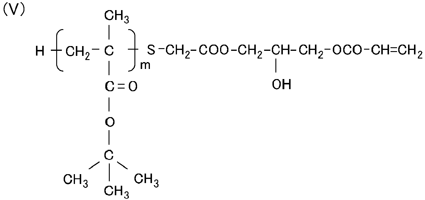
- a macromonomer No. 3 represented by the chemical formula (V) was obtained by being produced in the same manner as in the macromonomer No. 2 except that glycidyl methacrylate used in the production of the macromonomer No. 2 was changed to glycidyl acrylate.
- a macromonomer was produced in the same manner as in the macromonomer No. 2 except for changing:
- the perfluoro structure-containing monomer No. 1 is a material that affords the structure represented by the chemical structural formula (I).
- R1 represents a methylene group (CH 2 )
- R2 represents a hydrogen atom (H).
- Table 3 Compound name Blending amount (part(s) by mass) 1H,1H-Perfluoro (2,5-dimethyl-3,6-dioxanonan-1-ol) 48.2 2-Isocyanatoethyl methacrylate 15.5 Hydroquinone monomethyl ether 0.012 Zirconium(IV) acetylacetonate 0.3 n-Butyl acetate 100
- the precipitate was washed with a mixed solvent containing n-butyl acetate and 2-propanol at a ratio of 1:5, and was dried at a temperature of 80°C under a reduced-pressure state of 1,325 Pa or less for 3 hours to afford a graft copolymer No. 11, which was a copolymer of the macromonomer No. 1 and the perfluoro structure-containing monomer No. 1.
- Table 4 Compound name Blending amount (part(s) by mass) Macromonomer No. 1 75 Perfluoro structure-containing monomer No. 1 50 1,1'-Azobis(1 -acetoxy- 1 -phenyl ethane) 0.437 n-Butyl acetate 338
- Graft copolymers Nos. 21, 22, 31, 32, 41, 51, 52, 61 and 62 were prepared in the same manner as in the graft copolymer No. 11 except that the kind of the macromonomer, the kind of the perfluoro structure-containing monomer, and the blending amount of 1,1'-azobis(1-acetoxy-1-phenylethane) were set as shown in Table 5.
- Table 5 Graft copolymer No. Macromonomer Perfluoro structure-containing monomer 1,1'-Azobis(1-acetoxy-1-phenyl ethane) No. Part(s) by mass No.
- a graft copolymer was produced by the same method as in the graft copolymer No. 11 except that the perfluoro structure-containing monomer No. 1 was changed to 2,2,3,3,4,4,4-heptafluorobutyl acrylate having the structure represented by the following chemical formula (IX). Thus, a graft copolymer No. 90 was obtained.
- the peak top molecular weight of each of the obtained graft copolymers is shown in Table 6.
- the peak top molecular weight was measured with a gel permeation chromatograph (hereinafter sometimes referred to as "GPC") apparatus GPC-104 (from Shodex) after a measurement sample had been dissolved in tetrahydrofuran (hereinafter sometimes referred to as "THF") to prepare a solution having a concentration of 0.2 mass%.
- GPC gel permeation chromatograph
- THF tetrahydrofuran
- the weight-average molecular weight (Mw) of the sample was calculated from a calibration curve that had been prepared in advance using a polystyrene standard substance having a known molecular weight (SM-105 from Shodex).
- SM-105 polystyrene standard substance having a known molecular weight
- Table 6 Graft copolymer No. Peak top molecular weight (in terms of PS standard particles; ⁇ 10 3 ) 11 24 21 20 22 23 31 20 32 21 41 40 51 20 52 22 61 31 62 30 90 35
- Table 7 Material name Blending amount (part(s) by mass) Pentaerythritol triacrylate 95 Methyl ethyl ketone (MEK) 170 1-Hydroxycyclohexyl phenyl ketone 8 FLUOROLINK MD700 (product name; manufactured by Solvay Specialty Polymers) 40 Graft copolymer No. 11 27 Dispersion of zinc oxide particles in methyl ethyl ketone (product name; CX-Z410K, manufactured by Nissan Chemical Corporation) 25
- an endless-shaped electrophotographic belt made of a polyimide resin having carbon black dispersed therein the electrophotographic belt being mounted onto a full-color multifunctional peripheral (product name: imageRUNNER ADVANCE C5051; manufactured by Canon Inc.) as an intermediate transfer belt, a coating film of the coating material A was applied so as to have a dry thickness of 6 ⁇ m. Then, the resultant was dried at a temperature of 70°C for 3 minutes.
- the coating film was cured through irradiation with UV light using a high-pressure mercury lamp under the conditions of a peak illuminance at a wavelength of 365 nm of 200 mW/cm 2 , and a cumulative light quantity of 2 J/cm 2 to form a surface layer.
- an electrophotographic belt No. 1 was obtained.
- the resultant electrophotographic belt was subjected to the following evaluation 1 and evaluation 2.
- the hardness of the electrophotographic belt was measured by a nanoindentation method. Specifically, an indentation hardness was determined by performing a nanoindentation test using a microhardness tester (product name: PICODENTOR HM500; manufactured by Fischer Instruments) and using, as an indenter, a Vickers indenter under the condition of an indentation depth of from 100 nm to 200 nm.
- a microhardness tester product name: PICODENTOR HM500; manufactured by Fischer Instruments
- An electrophotographic image was formed using each of the electrophotographic belts obtained in Examples 1 to 11 and Comparative Example 1, and the resultant electrophotographic image was evaluated.
- the electrophotographic belt was mounted as an intermediate transfer belt onto a full-color multifunctional peripheral (product name: imageRUNNER ADVANCE C5760F; manufactured by Canon Inc.), and electrophotographic images were continuously formed on 30,000 sheets under the following conditions.
- the images were formed on 30,000 sheets by repeating the following cycle 300 times: a solid image having a toner laid-on level on the surface of the electrophotographic belt of 0.4 mg/cm 2 for each of cyan (C), magenta (M), yellow (Y), and black (K), and having an image ratio of 100% was formed on 97 sheets, and then a white solid image having a laid-on level on the surface of the electrophotographic belt of 0 mg/cm 2 for each of CMYK toners, and having an image ratio of 100% was formed on 3 sheets.
- the formation of the electrophotographic images was performed under an environment having a temperature of 30°C and a relative humidity of 80%.
- the paper used was "GF-C081" (A3 size, basis weight: 81.4 g/m 2 , thickness: 97 ⁇ m, whiteness: about 100%, manufactured by Canon Inc.).
- the white solid image having a laid-on level of 0 mg/cm 2 was visually observed, followed by the recognition of whether or not a streak-like image resulting from a cleaning failure of the surface of the electrophotographic belt was formed on the white solid image, onto which no toner had been intended to be transferred.
- Rank B A streak-like image resulting from a cleaning failure of the surface of the electrophotographic belt was found on the white solid image.
- a coating material was produced, and an electrophotographic belt No. 90 was obtained, in the same manner as in Example 1 except that the graft copolymer No. 11 was changed to the graft copolymer No. 90.
- the resultant electrophotographic belt No. 90 was subjected to the above-mentioned evaluation 1 and evaluation 2. In the evaluation 2, a streak-like image resulting from a cleaning failure occurred in the white solid image formed in the 100th cycle, and hence image formation was stopped at the completion of 200 cycles.
- Example 1 The evaluation results of Examples 1 to 11 and Comparative Example 1 are shown in Table 9.
- Table 9 Electrophotographic belt No. Evaluation 1 Evaluation 2 Indentation hardness (MPa) Evaluation rank Example 1 1 252 A Example 2 2 264 A Example 3 3 272 A Example 4 4 268 A Example 5 5 274 A Example 6 6 254 A Example 7 7 259 A Example 8 8 263 A Example 9 9 258 A Example 10 10 256 A Example 11 11 212 A Comparative Example 1 90 114 B
- the surface layer was abraded through repeated cleaning of the surface of the electrophotographic belt, and hence the PFPE in the surface layer was lost along with the abrasion. Presumably for this reason, the cleaning property of the surface of the electrophotographic belt was reduced over time.
- the PFPE in the surface layer is finely dispersed, and hence the hardness of the surface layer is maintained at a high level. Accordingly, even when the surface of the electrophotographic belt is repeatedly cleaned, the surface layer is hardly abraded. Besides, by virtue of the PFPE being finely dispersed, even when the surface layer is abraded, domains of the PFPE are present in a substantially uniform manner in the thickness direction of the surface layer. Conceivably for this reason, the cleaning property of the surface of the electrophotographic belt was hardly reduced even by repeated use.
- n-hexadecane contact angles for a thin film of the graft copolymer No. 21 and a thin film of the graft copolymer No. 90 are shown in Table 10.
- Table 10 n-Hexadecane contact angle (°) Graft copolymer No. 21 71 Graft copolymer No. 90 53
- Table 11 shows a list of CAS numbers and manufacturer names for materials referred to with generic names among the materials used in Examples.
- Table 11 Material name CAS number Manufacturer name tert-Butyl methacrylate monomer 585-07-9 Tokyo Chemical Industry Co., Ltd. 2,2'-Azobis(isobutyronitrile) 78-67-1 Tokyo Chemical Industry Co., Ltd. Thioglycolic acid 68-11-1 Tokyo Chemical Industry Co., Ltd. Triethylamine 121-44-8 Tokyo Chemical Industry Co., Ltd. Hydroquinone monomethyl ether 150-76-5 Tokyo Chemical Industry Co., Ltd. Glycidyl methacrylate 106-91-2 Tokyo Chemical Industry Co., Ltd. Glycidyl acrylate 106-90-1 Tokyo Chemical Industry Co., Ltd.
- an electrophotographic belt including at least: a base layer; and a surface layer containing the following A, B, and C:
Landscapes
- Physics & Mathematics (AREA)
- General Physics & Mathematics (AREA)
- Chemical & Material Sciences (AREA)
- Chemical Kinetics & Catalysis (AREA)
- Health & Medical Sciences (AREA)
- Medicinal Chemistry (AREA)
- Polymers & Plastics (AREA)
- Organic Chemistry (AREA)
- Spectroscopy & Molecular Physics (AREA)
- Electrostatic Charge, Transfer And Separation In Electrography (AREA)
- Addition Polymer Or Copolymer, Post-Treatments, Or Chemical Modifications (AREA)
- Macromonomer-Based Addition Polymer (AREA)
Abstract
Description
- The present disclosure relates to an electrophotographic belt to be used in an electrophotographic image forming apparatus, such as a copying machine or a printer, and an electrophotographic image forming apparatus including an electrophotographic belt.
- In an electrophotographic image forming apparatus capable of forming a full-color image, there has been widely adopted a tandem system in which toner images of respective colors of yellow, magenta, cyan, and black (YMCK) are superimposed on an intermediate transfer belt and then collectively transferred onto paper to provide a full-color image. As the intermediate transfer belt to be used in this case, there is known, for example, an electrophotographic belt including a base layer having carbon black dispersed in a binder resin, such as polyimide or polyether ether ketone.
- Along with a requirement for a further increase in image quality of an electrophotographic image, there is a demand that the intermediate transfer belt be further improved in secondary transfer characteristic for toner. In order to improve the secondary transfer property of the intermediate transfer belt, there is a proposal that perfluoropolyether be incorporated into a surface layer serving as a toner-carrying surface (hereinafter sometimes referred to simply as "surface") of the intermediate transfer belt to enhance toner releasability of the surface.
- In addition, in
Japanese Patent Application Laid-Open No. 2019-12265 - An investigation made by the inventors found that the comb-shaped graft copolymer according to
Japanese Patent Application Laid-Open No. 2019-12265 - At least one aspect of the present disclosure is directed to providing an electrophotographic belt excellent in environmental friendliness, and capable of satisfactorily maintaining the cleaning property of its surface over a long period of time. In addition, another aspect of the present disclosure is directed to providing an electrophotographic image forming apparatus capable of stably forming a high-quality electrophotographic image.
- According to one aspect of the present disclosure, there is provided an electrophotographic belt including at least a base layer and a surface layer. The surface layer contains the following A, B, and C:
- A: a compound 1 having a structure represented by a structural formula (I) and a structure represented by a structural formula (II):

- R1 represents a linking group, and
- R2 represents a hydrogen atom or a methyl group;

- R3 represents a hydrogen atom, a methyl group, or a methyl ester group,
- R4 represents a linking group,
- R5 represents a methyl group or a tert-butyl group, and
- "m" represents an integer of from 25 to 100;
- B: perfluoropolyether;
- C: a binder resin.
- In addition, according to another aspect of the present disclosure, there is provided an electrophotographic image forming apparatus including: an image bearing member configured to bear a toner image; and an intermediate transfer belt configured to carry and convey the toner image that is primarily transferred from the image bearing member in order to secondarily transfer the toner image onto a transfer material, wherein the intermediate transfer belt is the above-mentioned electrophotographic belt.
- Further features of the present disclosure will become apparent from the following description of exemplary embodiments with reference to the attached drawings.
-
-
FIG. 1 is a schematic sectional view of an image forming apparatus according to an embodiment of the present disclosure. -
FIG. 2 is a sectional view for illustrating the configuration of an intermediate transfer belt according to an embodiment of the present disclosure. - The reason why the satisfactory cleaning property of the surface of an electrophotographic belt including a surface layer having perfluoropolyether dispersed in a binder resin through use of the above-mentioned comb-shaped graft copolymer that is considered to be environmentally friendly is reduced over time is conceived to be as described below. That is, the comb-shaped graft copolymer in which the number of consecutive carbon atoms having fluorine atoms bonded thereto is set to 3 or less is conceivably reduced in ability to disperse the perfluoropolyether. Accordingly, it is difficult to finely disperse the perfluoropolyether in the binder resin. As a result, large domains of perfluoropolyether are caused to be present in the surface layer. The hardness of such surface layer is low, and hence its surface is worn down through repeated cleaning with a cleaning blade. It is conceived that, along with this, the perfluoropolyether is also lost from the surface layer, leading to a reduction in toner releasability of the surface.
- Based on such discussion, further investigations have been made, and as a result, it has been found that a compound having the structure represented by the above-mentioned chemical structural formula (I) and the structure represented by the above-mentioned chemical structural formula (II) has an environmentally friendly structure, and is excellent in ability to disperse perfluoropolyether in a binder resin.
- Exemplary embodiments of the present disclosure are described in the following in detail with reference to the attached drawings. However, specific aspects, for example, the dimensions, materials, shapes, relative positional relationship, and the like of structural elements described in the following embodiments may be appropriately changed depending on the structure of the apparatus to which the present disclosure is applied and various conditions, and the scope of the present disclosure is not limited only to the specific aspects.
-
FIG. 1 is a schematic sectional view of an electrophotographicimage forming apparatus 100, which is an electrophotographic image forming apparatus including an electrophotographic belt according to one embodiment of the present disclosure. - In the electrophotographic image forming apparatus, image forming units Py, Pm, Pc, and Pk of respective colors of yellow (Y), magenta (M), cyan (C), and black (K) are arranged in the stated order along a flat portion of an
intermediate transfer belt 7 that is an intermediate transfer member in a movement direction thereof. Herein, there are illustrated electrophotographicphotosensitive members charging rollers laser exposure devices devices primary transfer rollers - The yellow image forming unit Py includes, as an image bearing member, the drum-type electrophotographic photosensitive member (hereinafter sometimes referred to as "photosensitive drum" or "first image bearing member") 1Y. The
photosensitive drum 1Y is formed by laminating a charge generating layer, a charge transporting layer, and a surface protective layer in the stated order on a cylinder made of aluminum serving as a substrate. - In addition, the yellow image forming unit Py includes the
charging roller 2Y serving as a charging unit. The surface of thephotosensitive drum 1Y is uniformly charged by applying a charging bias to thecharging roller 2Y. - The
laser exposure device 3Y serving as an image exposure unit is arranged above thephotosensitive drum 1Y. Thelaser exposure device 3Y scans and exposes the surface of the uniformly chargedphotosensitive drum 1Y in accordance with image information, to thereby form an electrostatic latent image of a yellow color component on the surface of thephotosensitive drum 1Y. - The electrostatic latent image formed on the
photosensitive drum 1Y is developed with a toner serving as a developer by the developingdevice 4Y serving as a developing unit. The developingdevice 4Y includes a developing roller 4Ya serving as a developer carrier and a regulating blade 4Yb serving as a developer amount regulating member, and accommodates a yellow toner serving as a developer. The developing roller 4Ya having the yellow toner supplied thereto is brought into light pressure contact with thephotosensitive drum 1Y in a developing portion, and is rotated in a forward direction with a speed difference from thephotosensitive drum 1Y. The yellow toner conveyed to the developing portion by the developing roller 4Ya adheres to the electrostatic latent image formed on thephotosensitive drum 1Y when a developing bias is applied to the developing roller 4Ya. - As a result, a visible image (yellow toner image) is formed on the
photosensitive drum 1Y. - The
intermediate transfer belt 7 is tensioned on adrive roller 71, atension roller 72, and a drivenroller 73, and is brought into contact with thephotosensitive drum 1Y to be moved (driven to rotate) in a direction of the arrow in the figure. - The yellow toner image formed on the photosensitive drum (first image bearing member) 1Y having reached a primary transfer portion Ty is primarily transferred onto the
intermediate transfer belt 7 by a primary transfer member (primary transfer roller 5Y) arranged so as to be opposed to thephotosensitive drum 1Y through intermediation of theintermediate transfer belt 7. - Similarly, the above-mentioned image forming operation is performed in the image forming units Pm, Pc, and Pk of respective colors of magenta (M), cyan (C), and black (K) along with the movement of the
intermediate transfer belt 7, and toner images of four colors of yellow, magenta, cyan, and black are laminated on theintermediate transfer belt 7. The laminated four-color toner images are conveyed along with the movement of theintermediate transfer belt 7, and are collectively transferred onto a transfer material S (hereinafter sometimes referred to as "second image bearing member") conveyed at a predetermined timing by asecondary transfer roller 8 serving as a secondary transfer unit in a secondary transfer portion T'. In such secondary transfer, a transfer voltage of several kilovolts is generally applied in order to secure a sufficient transfer rate. - The transfer material S is supplied to a conveyance path by a
pickup roller 13 from acassette 12 in which the transfer material S is stored. The transfer material S supplied to the conveyance path is conveyed to the secondary transfer portion T' by aconveyance roller pair 14 and aregistration roller pair 15 in synchronization with the four-color toner images transferred onto theintermediate transfer belt 7. - The toner images transferred onto the transfer material S are fixed by a fixing device 9 to form, for example, a full-color image. The fixing device 9 includes a fixing
roller 91 including a heating unit and apressure roller 92, and fixes the unfixed toner images on the transfer material S by heating and pressurization. After that, the transfer material S is delivered to the outside of the apparatus by aconveyance roller pair 16, adelivery roller pair 17, and the like. - A
cleaning unit 11 of theintermediate transfer belt 7 is arranged on a downstream side with respect to the secondary transfer portion T' in a drive direction of theintermediate transfer belt 7, and removes a transfer residual toner remaining on theintermediate transfer belt 7 without being transferred onto the transfer material S in the secondary transfer portion T'. - As described above, the electrical transfer process of the toner images from the photosensitive member to the intermediate transfer belt and from the intermediate transfer belt to the transfer material is repeated. In addition, when recording on a large number of transfer materials is repeated, the electrical transfer process is further repeated.
- As illustrated in
FIG. 2 , anelectrophotographic belt 200 according to this embodiment is a laminate including at least two layers: abase layer 21 and asurface layer 22. Thesurface layer 22 constitutes the toner-carrying surface of theelectrophotographic belt 200, that is, a surface 200-1. - The configuration of the electrophotographic belt according to the present disclosure is not limited to the laminate of the above-mentioned two layers. For example, there may be adopted a configuration in which a primer layer (not shown) for improving adhesiveness, or a stress relaxation layer for suppressing the cracking of the
surface layer 22 or an intermediate layer for suppressing a bled substance (none of which is shown) is arranged between thebase layer 21 and thesurface layer 22. - The shape of the
base layer 21 is a cylindrical shape that is an endless roll or belt shape. - Examples of a material suitable for the
base layer 21 include the following materials: polyether ether ketone; polyethylene terephthalate; polybutylene naphthalate; polyester; polyimide; polyamide; polyamideimide; polyacetal; polyphenylene sulfide; and polyvinylidene fluoride. - A resin for the
base layer 21 may have electroconductivity imparted thereto by adding metal powder, electroconductive oxide powder, electroconductive carbon, a lithium salt, an ionic liquid, or any other electroconductive compound. In Examples to be described later, polyimide having added thereto carbon black was used from the viewpoint of enabling the achievement of excellent electroconductivity and environmental stability. However, a combination of any other resin and electroconductivity-imparting agent among the listed examples may be used. - The thickness of the
base layer 21 is preferably 10 µm or more and 500 µm or less. This is because of the following reasons: when the thickness is less than 10 µm, mechanical strength may be markedly reduced; and when the thickness is more than 500 µm, rigidity may become excessively strong, and hence it may be difficult to use the intermediate transfer belt as an intermediate transfer member. - The
surface layer 22 is formed on thebase layer 21, serves as the outermost layer of the intermediate transfer belt according to this embodiment, and contains all of the following A, B, and C: - A: a compound 1 (hereinafter sometimes referred to as "graft copolymer") having the structure represented by the above-mentioned chemical structural formula (I) and the structure represented by the above-mentioned chemical structural formula (II);
- B: perfluoropolyether (hereinafter sometimes referred to as "PFPE"); and
- C: a binder resin.
- The
surface layer 22 may contain a photopolymerization initiator, an electroconductive substance, or the like in addition to the above-mentioned binder resin, PFPE, and graft copolymer. - One or more resins selected from the group consisting of: an acrylic resin; a methacrylic resin; and an epoxy resin may be used as the binder resin. The term "one or more resins" encompasses a mixed resin of resins selected from the above-mentioned group.
- The binder resin functions as a dispersion medium for the PFPE. In addition, the binder resin is a material for securing the adhesiveness of the surface layer to the
base layer 21, and securing the mechanical strength of the surface layer itself. - Of the above-mentioned binder resins, a methacrylic resin or an acrylic resin is preferably used because the PFPE for forming the
surface layer 22 of the electrophotographic belt can be satisfactorily dispersed. The methacrylic resin and the acrylic resin are hereinafter collectively referred to as "acrylic-based resin". - Examples of a polymerizable monomer for forming the acrylic-based resin include the following (i) and (ii). A product commercially available as a coating material may also be used as the polymerizable monomer.
- (i) At least one kind of acrylate selected from the group consisting of the following acrylates: pentaerythritol triacrylate; pentaerythritol tetraacrylate; ditrimethylolpropane tetraacrylate; dipentaerythritol hexaacrylate; an alkyl acrylate; benzyl acrylate; phenyl acrylate; ethylene glycol diacrylate; and bisphenol A diacrylate.
- (ii) At least one kind of methacrylate selected from the group consisting of the following methacrylates: pentaerythritol trimethacrylate; pentaerythritol tetramethacrylate; ditrimethylolpropane tetramethacrylate; dipentaerythritol hexamethacrylate; an alkyl methacrylate; benzyl methacrylate; phenyl methacrylate; ethylene glycol dimethacrylate; and bisphenol A dimethacrylate.
- The binder resin preferably has a high hardness in consideration of rubbing with other members, such as a photosensitive member and a cleaning blade. For this reason, it is preferred that the acrylic-based resin be caused to have a higher hardness through use of a larger amount of a bi- or higher functional crosslinkable monomer.
- In addition, as a method of forming the acrylic resin from such polymerizable monomer, there is given a method involving adding a photopolymerization initiator and causing polymerization with an electron beam or UV light.
- Examples of the photopolymerization initiator include the following initiators: radical-generating photopolymerization initiators, such as benzophenone, a thioxanthone-based initiator, benzyl dimethyl ketal, an α-hydroxy ketone, an α-hydroxyalkylphenone, an α-amino ketone, an α-aminoalkylphenone, a monoacylphosphine oxide, a bisacylphosphine oxide, hydroxybenzophenone, aminobenzophenone, a titanocene-based initiator, an oxime ester, and an oxyphenyl acetic acid ester.
- The content of the binder resin in the surface layer is preferably set to 20 mass% or more and 70 mass% or less with respect to the mass of the total solid content of the
surface layer 22 in order to allow the surface layer to have excellent strength, and allow the outer surface of the surface layer to carry excellent toner releasability. - The perfluoropolyether (hereinafter also referred to as "PFPE") refers to an oligomer or a polymer including a perfluoroalkylene ether as a repeating unit.
- Examples of the repeating unit of the perfluoroalkylene ether include repeating units of a perfluoromethylene ether, a perfluoroethylene ether, and a perfluoropropylene ether. A commercially available product may be used as the PFPE. Examples of the commercially available product include, but not limited to, a PFPE represented by the structural formula (1) (e.g., Demnum S-200 and Demnum S-65 (product names), manufactured by Daikin Industries, Ltd.), a PFPE represented by the structural formula (2) (e.g., Krytox GPL-107, Krytox GPL-106, and Krytox GPL-105 (product names), manufactured by Chemours Company), a PFPE represented by the structural formula (3) (e.g., Fomblin M60 and Fomblin Z25 (product names), manufactured by Solvay Specialty Polymers), and a PFPE represented by the structural formula (4) (e.g., Fomblin Y45 and Fomblin Y25 (product names), manufactured by Solvay Specialty Polymers).

- In the formula (1), "n" represents a positive number, and "n" represents a number within a range in which a kinematic viscosity at 40°C satisfies the range of from 10 mm2/s to 300 mm2/s.
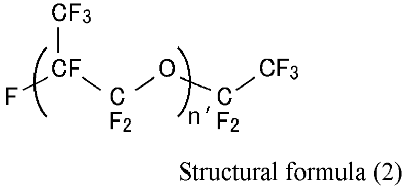
- In the formula (2), n' represents a positive number, and n' represents a number within a range in which the kinematic viscosity at 40°C satisfies the range of from 5 mm2/s to 1,200 mm2/s.

- In the formula (3), n" and "m" each represent a positive number, m/n" is a number of 0.5 or more and 2 or less, and n"+m is such a number that the kinematic viscosity at 40°C satisfies the range of from 10 mm2/s to 900 mm2/s.

- In the formula (4), n'" and m' each represent a positive number, m'/n‴ is a number of 20 or more and 1,000 or less, and n"'+m' is a number within a range in which the kinematic viscosity at 40°C satisfies the range of from 10 mm2/s to 700 mm2/s.
- In addition, the PFPE may have a reactive functional group capable of forming a bond or a bond-like state with the binder resin, or a non-reactive functional group incapable of forming a bond or a bond-like state with the binder resin. Examples of the reactive functional group include an acrylic group, a methacrylic group, and an oxysilanyl group. In addition, examples of the non-reactive functional group include a hydroxyl group, a trifluoromethyl group, and a methyl group.
- Examples of a commercially available product of the PFPE having the above-mentioned reactive functional group include the following products: "FLUOROLINK MD700", "FLUOROLINK AD1700", and "FLUOROLINK S10" (product names; manufactured by Solvay S.A.); and "Optool DAC" (product name; manufactured by Daikin Industries, Ltd.). The "MD-500" is a PFPE having a methacrylic group as a functional group, and the "FLUOROLINK AD 1700" is a PFPE having an acrylic group as a functional group.
- In addition, examples of a commercially available product of the PFPE having the above-mentioned non-reactive functional group include: "FLUOROLINK D10H", "FLUOROLINK D4000", and "Fomblin Z15" (product names, manufactured by Solvay S.A.); and "Demnum S-20", "Demnum S-65", and "Demnum S200" (product names, manufactured by Daikin Industries, Ltd.).
- The compound 1 according to the component A has the structure represented by the chemical structural formula (I) and the structure represented by the chemical structural formula (II). The compound 1 functions as a dispersant for dispersing the PFPE in the binder resin. The graft copolymer that is the compound 1 has both of a first unit represented by the following chemical structural formula (I) and a second unit represented by the following chemical structural formula (II).
- The first unit is a moiety excellent in affinity for the PFPE, while the second unit is excellent in affinity for the binder resin. In addition, the first unit has a perfluoromethyl group as a side chain. This conceivably compensates for a reduction in ability to disperse the PFPE in the binder resin caused by introducing an oxygen atom and setting the number of consecutive carbon atoms in the perfluoroalkyl group to 3 or less. As a result, the compound 1 according to the present disclosure can allow the PFPE having low surface free energy to be better dispersed in the binder resin.


- In the formula (II),
- R3 represents a hydrogen atom, a methyl group, or a methyl ester group,
- R4 represents a linking group,
- R5 represents a methyl group or a tert-butyl group, and
- "m" represents an integer of from 25 to 100.
- Examples of the linking group R1 in the chemical structural formula (I) include an alkylene group having 1 to 6 carbon atoms, and a group consisting of a carbon atom, a hydrogen atom, a nitrogen atom, and an oxygen atom, and having a main chain of which a number of atoms constituting the main chain is 6 or less. Specific examples thereof include an alkylene group having 1 to 6 carbon atoms (e.g., -CH2- or -CH2CH2-), and a group represented by the following structural formula (i) in which a methylene group (CH2) and an ethylene group (CH2CH2) are bonded via a urethane bond (-OC(=O)NH-). Here, in the structural formula (i), the main chain means -C-O-C-N-C-C-.
- (i)
-CH2OC(=O)NHCH2CH2-
- Examples of the linking group R4 in the chemical structural formula (II) include a group consisting of a carbon atom, a hydrogen atom, an oxygen atom and a sulfur atom, and having a main chain of which a number of atoms constituting the main chain is 9 or less; and a group consisting of a carbon atom, a hydrogen atom, a nitrogen atom, an oxygen atom, and a sulfur atom, and having a main chain of which a number of atoms constituting the main chain is 9 or less. Specific examples of such group are represented by the following structural formulae (ii) to (iv). In the structural formula (ii), the main chain means -S-C-C-O-C-C-C-O-C-. In the structural formula (iii), the main chain means -S-C-C-C-N-C-C-O-C-. Further, in the structural formula (iv), the main chain means -S-C-C-N-C-C-O-C-.
- (ii)
-SCH2C(=O)OCH2CH(OH)CH2OC(=O)-
- (iii)
-SCH2CH2C(=O)NHCH2CH2OC(=O)-
- (iv)
-SCH2C(=O)NHCH2CH2OC(=O)-
- The peak top molecular weight of the compound 1 is preferably 20,000 or more and 40,000 or less.
- When the peak top molecular weight falls within the above-mentioned numerical range, a high steric hindrance effect can be expressed to effectively suppress aggregation between PFPE molecules.
- The compound 1 may also be defined as an acrylic resin or methacrylic resin having grafted thereonto a group having a perfluoroalkyl group having 3 carbon atoms. Such compound may be obtained by copolymerizing a macromonomer and a monofunctional monomer. Here, the macromonomer is a compound having a high molecular weight as compared to a general monomer, and having a reactive group. The graft copolymer may be obtained by polymerizing a macromonomer having one polymerizable functional group per molecule out of such macromonomers with a monomer having one polymerizable functional group per molecule.
- According to one aspect of the present disclosure, the electrophotographic belt excellent in environmental friendliness and capable of forming a satisfactory electrophotographic image over a long period of time can be obtained. In addition, according to one aspect of the present disclosure, the electrophotographic image forming apparatus capable of stably forming a high-quality electrophotographic image can be obtained.
- The electrophotographic belt according to the present disclosure is described in more detail below by way of non-limiting specific examples.
- A macromonomer having a methyl methacrylate segment (product name: AA-6; manufactured by Toagosei Co., Ltd., R3 and R5: -CH3, number-average molecular weight: 6,000) was prepared as a macromonomer No. 1.
- Materials shown in Table 1 below were loaded into a glass flask with a reflux condenser tube, and nitrogen purging was performed while a temperature in the flask was kept at 15°C in a water bath.
Table 1 Compound name Blending amount (part(s) by mass) tert-Butyl methacrylate monomer 10.0 Acetone 14.5 Toluene 68.5 2,2'-Azobis(isobutyronitrile) 0.5 Thioglycolic acid 0.3 - After that, under a nitrogen atmosphere, the temperature of the water bath was set so that the temperature of the reaction liquid became 85°C, and a polymerization reaction was performed for 5 hours. The polymerization reaction was terminated by ice cooling to afford a solution having dissolved therein a compound represented by the chemical formula (III).

- Then, 60 parts by mass of toluene was additionally loaded, and triethylamine and hydroquinone monomethyl ether were added at 0.5 wt% with respect to the loading amount of the tert-butyl methacrylate monomer and 200 ppm with respect to the loading amount of the tert-butyl methacrylate monomer, respectively. Glycidyl methacrylate was added in a 10-fold molar amount with respect to the acid value of the resultant chemical formula (III), and a reaction was performed at a temperature of 110°C for 11 hours. The reaction was terminated by water cooling, n-hexane was added, and a precipitate was obtained by centrifugation. After that, the precipitate was dried under reduced pressure under the conditions of a temperature of 80°C and 1,325 Pa or less for 3 hours to afford a macromonomer No. 2 represented by the formula (IV).

- A macromonomer No. 3 represented by the chemical formula (V) was obtained by being produced in the same manner as in the macromonomer No. 2 except that glycidyl methacrylate used in the production of the macromonomer No. 2 was changed to glycidyl acrylate.
- A macromonomer was produced in the same manner as in the macromonomer No. 2 except for changing:
- the tert-butyl methacrylate monomer to a methyl methacrylate monomer;
- thioglycolic acid to 3-mercaptopropionic acid;
- glycidyl methacrylate to 2-isocyanatoethyl methacrylate;
- triethylamine to zirconium(IV) acetylacetonate;
- the 10-fold molar amount to a 2-fold molar amount; and
- the reaction at a temperature of 110°C for 11 hours to a reaction at a temperature of 50°C for 24 hours. A macromonomer No. 4 represented by the chemical formula (VI) was obtained.

- A grade having a number-average molecular weight of 2,800 of POLY(METHYL METHACRYLATE) MACROMONOMER, ΩVINYL-TERMINATED from Polymer Source, Inc. was prepared as a macromonomer No. 5.
- A grade having a number-average molecular weight of 9,900 of POLY(METHYL METHACRYLATE) MACROMONOMER, ΩVINYL-TERMINATED from Polymer Source, Inc. was prepared as a macromonomer No. 6.
- The structures of the macromonomers Nos. 2 to 6 are shown in Table 2. The value of "m" was determined from a peak area ratio of 1H NMR in a CDCl3 solvent.
Table 2 Macromonomer No. m (average value) R3 R4 R5 2 45 Methyl SCH2COOCH2CH(OH)CH2OCO tert-Butyl 3 42 Hydrogen SCH2COOCH2CH(OH)CH2OCO tert-Butyl 4 82 Methyl SCH2CH2CONHCH2CH2OCO Methyl 5 27 Methyl ester CH2 Methyl 6 98 Methyl ester CH2 Methyl - 1H,1H-Perfluoro(2,5-dimethyl-3,6-dioxanonanoyl) acrylate having the structure represented by the following chemical formula (VIII) was used as a perfluoro structure-containing monomer No. 1. The perfluoro structure-containing monomer No. 1 is a material that affords the structure represented by the chemical structural formula (I). In the structure according to the chemical structural formula (I) to be formed by the perfluoro structure-containing monomer No. 1, R1 represents a methylene group (CH2), and R2 represents a hydrogen atom (H).

- Materials shown in Table 3 below were loaded into a flask made of glass with a stirrer, a reflux condenser, a nitrogen gas inlet tube, a thermostatic bath, and a temperature gauge, and the materials were mixed at a temperature of 20°C under a nitrogen atmosphere for 30 minutes. Then, the mixture was heated to a temperature of 50°C and subjected to a reaction for 24 hours to afford a perfluoro structure-containing monomer No. 2 represented by the chemical formula (VII).
Table 3 Compound name Blending amount (part(s) by mass) 1H,1H-Perfluoro (2,5-dimethyl-3,6-dioxanonan-1-ol) 48.2 2-Isocyanatoethyl methacrylate 15.5 Hydroquinone monomethyl ether 0.012 Zirconium(IV) acetylacetonate 0.3 n- Butyl acetate 100 
- Materials shown in Table 4 below were loaded into a flask made of glass with a stirrer, a reflux condenser, a nitrogen gas inlet tube, a thermostatic bath, and a temperature gauge, and the materials were mixed at 20°C under a nitrogen atmosphere for 30 minutes. Then, heating was performed so that the temperature of a reaction liquid became from 85°C to 90°C, followed by a reaction for 5 hours. The reaction was terminated by ice cooling, and 1,500 parts by mass of 2-propanol was added to afford a precipitate. The precipitate was washed with a mixed solvent containing n-butyl acetate and 2-propanol at a ratio of 1:5, and was dried at a temperature of 80°C under a reduced-pressure state of 1,325 Pa or less for 3 hours to afford a graft copolymer No. 11, which was a copolymer of the macromonomer No. 1 and the perfluoro structure-containing monomer No. 1.
Table 4 Compound name Blending amount (part(s) by mass) Macromonomer No. 1 75 Perfluoro structure-containing monomer No. 1 50 1,1'-Azobis(1 -acetoxy- 1 -phenyl ethane) 0.437 n-Butyl acetate 338 - Graft copolymers Nos. 21, 22, 31, 32, 41, 51, 52, 61 and 62 were prepared in the same manner as in the graft copolymer No. 11 except that the kind of the macromonomer, the kind of the perfluoro structure-containing monomer, and the blending amount of 1,1'-azobis(1-acetoxy-1-phenylethane) were set as shown in Table 5.
Table 5 Graft copolymer No. Macromonomer Perfluoro structure-containing monomer 1,1'-Azobis(1-acetoxy-1-phenyl ethane) No. Part(s) by mass No. Part(s) by mass Part(s) by mass 11 1 75 1 50 0.437 21 2 75 1 50 0.437 22 2 75 2 50 0.437 31 3 75 1 50 0.437 32 3 75 2 50 0.437 41 4 75 1 50 0.300 51 5 75 1 50 0.437 52 5 75 2 50 0.437 61 6 75 1 50 0.437 62 6 75 2 50 0.437 - A graft copolymer was produced by the same method as in the graft copolymer No. 11 except that the perfluoro structure-containing monomer No. 1 was changed to 2,2,3,3,4,4,4-heptafluorobutyl acrylate having the structure represented by the following chemical formula (IX). Thus, a graft copolymer No. 90 was obtained.

- The peak top molecular weight of each of the obtained graft copolymers is shown in Table 6. The peak top molecular weight was measured with a gel permeation chromatograph (hereinafter sometimes referred to as "GPC") apparatus GPC-104 (from Shodex) after a measurement sample had been dissolved in tetrahydrofuran (hereinafter sometimes referred to as "THF") to prepare a solution having a concentration of 0.2 mass%. The molecular weight was measured using a column, which had been obtained by connecting one each of "GPC KF-603" and "GPC KF-604" from Shodex, at a column temperature of 40°C and a flow rate of THF of 1.0 mL/min. The weight-average molecular weight (Mw) of the sample was calculated from a calibration curve that had been prepared in advance using a polystyrene standard substance having a known molecular weight (SM-105 from Shodex).
Table 6 Graft copolymer No. Peak top molecular weight (in terms of PS standard particles; ×103) 11 24 21 20 22 23 31 20 32 21 41 40 51 20 52 22 61 31 62 30 90 35 - Materials shown in Table 7 below were mixed using a homogenizer to provide a coating material A.
Table 7 Material name Blending amount (part(s) by mass) Pentaerythritol triacrylate 95 Methyl ethyl ketone (MEK) 170 1- Hydroxycyclohexyl phenyl ketone 8 FLUOROLINK MD700 (product name; manufactured by Solvay Specialty Polymers) 40 Graft copolymer No. 11 27 Dispersion of zinc oxide particles in methyl ethyl ketone (product name; CX-Z410K, manufactured by Nissan Chemical Corporation) 25 - Onto the outer peripheral surface of an endless-shaped electrophotographic belt made of a polyimide resin having carbon black dispersed therein, the electrophotographic belt being mounted onto a full-color multifunctional peripheral (product name: imageRUNNER ADVANCE C5051; manufactured by Canon Inc.) as an intermediate transfer belt, a coating film of the coating material A was applied so as to have a dry thickness of 6 µm. Then, the resultant was dried at a temperature of 70°C for 3 minutes. After that, the coating film was cured through irradiation with UV light using a high-pressure mercury lamp under the conditions of a peak illuminance at a wavelength of 365 nm of 200 mW/cm2, and a cumulative light quantity of 2 J/cm2 to form a surface layer. Thus, an electrophotographic belt No. 1 was obtained. The resultant electrophotographic belt was subjected to the following evaluation 1 and evaluation 2.
- The hardness of the electrophotographic belt was measured by a nanoindentation method. Specifically, an indentation hardness was determined by performing a nanoindentation test using a microhardness tester (product name: PICODENTOR HM500; manufactured by Fischer Instruments) and using, as an indenter, a Vickers indenter under the condition of an indentation depth of from 100 nm to 200 nm.
- An electrophotographic image was formed using each of the electrophotographic belts obtained in Examples 1 to 11 and Comparative Example 1, and the resultant electrophotographic image was evaluated.
- That is, the electrophotographic belt was mounted as an intermediate transfer belt onto a full-color multifunctional peripheral (product name: imageRUNNER ADVANCE C5760F; manufactured by Canon Inc.), and electrophotographic images were continuously formed on 30,000 sheets under the following conditions. With regard to the formation of the electrophotographic images, the images were formed on 30,000 sheets by repeating the following cycle 300 times: a solid image having a toner laid-on level on the surface of the electrophotographic belt of 0.4 mg/cm2 for each of cyan (C), magenta (M), yellow (Y), and black (K), and having an image ratio of 100% was formed on 97 sheets, and then a white solid image having a laid-on level on the surface of the electrophotographic belt of 0 mg/cm2 for each of CMYK toners, and having an image ratio of 100% was formed on 3 sheets. The formation of the electrophotographic images was performed under an environment having a temperature of 30°C and a relative humidity of 80%. In addition, the paper used was "GF-C081" (A3 size, basis weight: 81.4 g/m2, thickness: 97 µm, whiteness: about 100%, manufactured by Canon Inc.).
- Then, the white solid image having a laid-on level of 0 mg/cm2 was visually observed, followed by the recognition of whether or not a streak-like image resulting from a cleaning failure of the surface of the electrophotographic belt was formed on the white solid image, onto which no toner had been intended to be transferred.
- Then, when a streak-like image was observed, the cleaning blade brought into abutment with the surface of the electrophotographic belt was visually observed, followed by the recognition of whether or not the toner that had not been secondarily transferred (transfer residual toner) on the surface of the electrophotographic belt had been cleaned off by the cleaning blade. Then, when it was able to be recognized that the transfer residual toner had not been cleaned off by the cleaning blade, it was judged that the streak-like image resulted from a cleaning failure of the surface of the electrophotographic belt. In this evaluation, evaluation was performed by the following criteria based on the result of the above-mentioned observation.
- Rank A: A streak-like image resulting from a cleaning failure of the surface of the electrophotographic belt was not found on the white solid image.
- Rank B: A streak-like image resulting from a cleaning failure of the surface of the electrophotographic belt was found on the white solid image.
- Coating materials were produced, and electrophotographic belts Nos. 2 to 10 were obtained, in the same manner as in Example 1 except that the graft copolymer No. 11 was changed as shown in Table 8. The resultant electrophotographic belts were each subjected to the above-mentioned evaluation 1 and evaluation 2.
Table 8 Electrophotographic belt No. Graft copolymer No. Example 1 1 11 Example 2 2 21 Example 3 3 22 Example 4 4 31 Example 5 5 32 Example 6 6 41 Example 7 7 51 Example 8 8 52 Example 9 9 61 Example 10 10 62 - 95 Parts by mass of pentaerythritol triacrylate was changed to 40 parts by mass of bisphenol A-type epoxy acrylate (EBECRYL 600 manufactured by Daicel-Allnex Ltd.) and 55 parts by mass of pentaerythritol triacrylate. In the same manner as in Example 2 except for such change, a coating material was produced, and an electrophotographic belt No. 11 was obtained. The resultant electrophotographic belt was subjected to the above-mentioned evaluation 1 and evaluation 2.
- A coating material was produced, and an electrophotographic belt No. 90 was obtained, in the same manner as in Example 1 except that the graft copolymer No. 11 was changed to the graft copolymer No. 90. The resultant electrophotographic belt No. 90 was subjected to the above-mentioned evaluation 1 and evaluation 2. In the evaluation 2, a streak-like image resulting from a cleaning failure occurred in the white solid image formed in the 100th cycle, and hence image formation was stopped at the completion of 200 cycles.
- The evaluation results of Examples 1 to 11 and Comparative Example 1 are shown in Table 9.
Table 9 Electrophotographic belt No. Evaluation 1 Evaluation 2 Indentation hardness (MPa) Evaluation rank Example 1 1 252 A Example 2 2 264 A Example 3 3 272 A Example 4 4 268 A Example 5 5 274 A Example 6 6 254 A Example 7 7 259 A Example 8 8 263 A Example 9 9 258 A Example 10 10 256 A Example 11 11 212 A Comparative Example 1 90 114 B - The results for the evaluation 1 and evaluation 2 of the electrophotographic belt No. 90 according to Comparative Example 1 are conceivably due to a low ability to disperse the PFPE in the binder resin resulting from a difference between the surface free energy of the comb-shaped graft copolymer No. 90 and the surface free energy of each of the comb-shaped graft copolymers used in Examples. In the electrophotographic belt No. 90, the PFPE in the surface layer was not finely dispersed, and hence, as apparent from the result of the evaluation 1, the hardness of the surface layer was reduced. Conceivably as a result of this, the surface layer was abraded through repeated cleaning of the surface of the electrophotographic belt, and hence the PFPE in the surface layer was lost along with the abrasion. Presumably for this reason, the cleaning property of the surface of the electrophotographic belt was reduced over time.
- Meanwhile, in the electrophotographic belt according to each of Examples, the PFPE in the surface layer is finely dispersed, and hence the hardness of the surface layer is maintained at a high level. Accordingly, even when the surface of the electrophotographic belt is repeatedly cleaned, the surface layer is hardly abraded. Besides, by virtue of the PFPE being finely dispersed, even when the surface layer is abraded, domains of the PFPE are present in a substantially uniform manner in the thickness direction of the surface layer. Conceivably for this reason, the cleaning property of the surface of the electrophotographic belt was hardly reduced even by repeated use.
- In order to demonstrate the difference in surface free energy between the graft copolymers of Examples and Comparative Example, n-hexadecane contact angles for a thin film of the graft copolymer No. 21 and a thin film of the graft copolymer No. 90 are shown in Table 10.
Table 10 n-Hexadecane contact angle (°) Graft copolymer No. 21 71 Graft copolymer No. 90 53 - Table 11 shows a list of CAS numbers and manufacturer names for materials referred to with generic names among the materials used in Examples.
Table 11 Material name CAS number Manufacturer name tert-Butyl methacrylate monomer 585-07-9 Tokyo Chemical Industry Co., Ltd. 2,2'-Azobis(isobutyronitrile) 78-67-1 Tokyo Chemical Industry Co., Ltd. Thioglycolic acid 68-11-1 Tokyo Chemical Industry Co., Ltd. Triethylamine 121-44-8 Tokyo Chemical Industry Co., Ltd. Hydroquinone monomethyl ether 150-76-5 Tokyo Chemical Industry Co., Ltd. Glycidyl methacrylate 106-91-2 Tokyo Chemical Industry Co., Ltd. Glycidyl acrylate 106-90-1 Tokyo Chemical Industry Co., Ltd. Methyl methacrylate monomer 80-62-6 Tokyo Chemical Industry Co., Ltd. 2-Isocyanatoethyl methacrylate 30674-80-7 Tokyo Chemical Industry Co., Ltd. Zirconium(IV) acetylacetonate 17501-44-9 Tokyo Chemical Industry Co., Ltd. 3-Mercaptopropionic acid 107-96-0 Tokyo Chemical Industry Co., Ltd. 1H, 1H-Perfluoro(2,5-dimethyl-3,6-dioxanonanoyl) acrylate 17559-01-2 Manchester Organics Ltd. 1H,1H-Heptadecafluoro(2,5-dimethyl-3,6-dioxanonan-1-ol) 14548-74-4 Apollo Scientific Ltd. 1,1'-Azobis(1-acetoxy-1-phenylethane) 57908-47-1 Otsuka Chemical Co., Ltd. Pentaerythritol triacrylate 3524-68-3 Sigma-Aldrich 1-Hydroxycyclohexyl phenyl ketone 947-19-3 Tokyo Chemical Industry Co., Ltd. 2,2,3,3,4,4,4-Heptafluorobutyl acrylate 13695-31-3 Tokyo Chemical Industry Co., Ltd. - While the present disclosure has been described with reference to exemplary embodiments, it is to be understood that the disclosure is not limited to the disclosed exemplary embodiments. The scope of the following claims is to be accorded the broadest interpretation so as to encompass all such modifications and equivalent structures and functions.
- Provided is an electrophotographic belt including at least: a base layer; and a surface layer containing the following A, B, and C:
- A: a compound 1 having structures represented by formula (I) and formula (II):

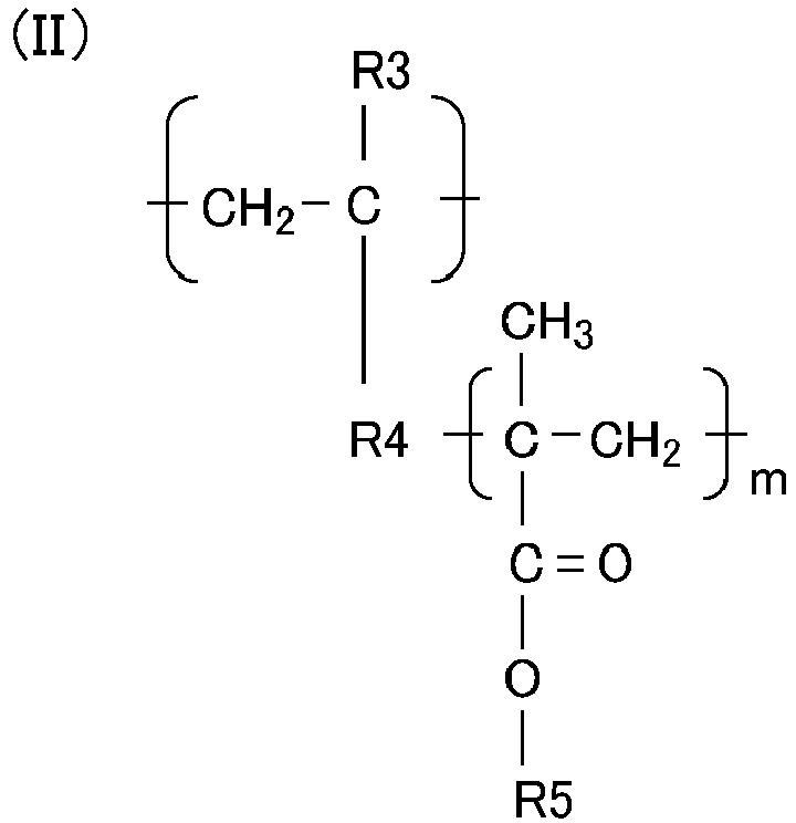
- B: perfluoropolyether;
- C: a binder resin.
Claims (8)
- An electrophotographic belt comprising at least:a base layer; anda surface layer containing the following A, B, and C:A: a compound 1 having a structure represented by a structural formula (I) and a structure represented by a structural formula (II):
 R1 represents a linking group, andR2 represents a hydrogen atom or a methyl group;
 R3 represents a hydrogen atom, a methyl group, or a methyl ester group,R4 represents a linking group,R5 represents a methyl group or a tert-butyl group, and"m" represents an integer of from 25 to 100;B: perfluoropolyether;C: a binder resin.
 - The electrophotographic belt according to claim 1, wherein the linking group R1 isan alkylene group having 1 to 6 carbon atoms; ora group consisting of a carbon atom, a hydrogen atom, a nitrogen atom, and an oxygen atom, and having a main chain of which a number of atoms constituting the main chain is 6 or less.
- The electrophotographic belt according to claim 1 or 2, wherein the linking group R1 is a group represented by the following structural formula (i).(i)
-CH2OC(=O)NHCH2CH2-
- The electrophotographic belt according to any one of claims 1 to 3, wherein the linking group R4 is:a group consisting of a carbon atom, a hydrogen atom, an oxygen atom, and a sulfur atom, and having a main chain of which a number of atoms constituting the main chain is 9 or less; ora group consisting of a carbon atom, a hydrogen atom, a nitrogen atom, an oxygen atom, and a sulfur atom, and having a main chain of which a number of atoms constituting the main chain is 9 or less.
- The electrophotographic belt according to any one of claims 1 to 4, wherein the linking group R4 is any one selected from the group consisting of the following structural formulae (ii) to (iv).(ii)
-SCH2C(=O)OCH2CH(OH)CH2OC(=O)-
(iii)
-SCH2CH2C(=O)NHCH2CH2OC(=O)-
(iv)
-SCH2C(=O)NHCH2CH2OC(=O)-
- The electrophotographic belt according to any one of claims 1 to 5, wherein the binder resin is one or more resins selected from the group consisting of: an acrylic resin; a methacrylic resin; and an epoxy resin.
- The electrophotographic belt according to any one of claims 1 to 6, wherein the compound 1 has a peak top molecular weight of 20,000 or more and 40,000 or less.
- An electrophotographic image forming apparatus comprising:an image bearing member configured to bear a toner image; andan intermediate transfer belt configured to carry and convey the toner image that is primarily transferred from the image bearing member in order to secondarily transfer the toner image onto a transfer material,wherein the intermediate transfer belt is the electrophotographic belt of any one of claims 1 to 7.
Applications Claiming Priority (2)
| Application Number | Priority Date | Filing Date | Title |
|---|---|---|---|
| JP2021072919 | 2021-04-22 | ||
| JP2022041929A JP2022167788A (en) | 2021-04-22 | 2022-03-16 | Electrophotographic belt and electrophotographic image formation device |
Publications (2)
| Publication Number | Publication Date |
|---|---|
| EP4083093A1 true EP4083093A1 (en) | 2022-11-02 |
| EP4083093B1 EP4083093B1 (en) | 2024-01-03 |
Family
ID=81346157
Family Applications (1)
| Application Number | Title | Priority Date | Filing Date |
|---|---|---|---|
| EP22169166.0A Active EP4083093B1 (en) | 2021-04-22 | 2022-04-21 | Electrophotographic belt and electrophotographic image forming apparatus |
Country Status (3)
| Country | Link |
|---|---|
| US (1) | US11740572B2 (en) |
| EP (1) | EP4083093B1 (en) |
| CN (1) | CN115236958B (en) |
Families Citing this family (1)
| Publication number | Priority date | Publication date | Assignee | Title |
|---|---|---|---|---|
| JP2023107611A (en) * | 2022-01-24 | 2023-08-03 | 富士フイルムビジネスイノベーション株式会社 | Endless belt, transfer device and image forming device |
Citations (3)
| Publication number | Priority date | Publication date | Assignee | Title |
|---|---|---|---|---|
| JP2019012265A (en) | 2017-06-29 | 2019-01-24 | キヤノン株式会社 | Electrophotographic belt and electrophotographic image forming apparatus |
| JP2019184728A (en) * | 2018-04-05 | 2019-10-24 | コニカミノルタ株式会社 | Electrophotographic image formation method |
| US10585365B2 (en) * | 2018-02-08 | 2020-03-10 | Konica Minolta, Inc. | Image bearing member for electrophotography |
Family Cites Families (20)
| Publication number | Priority date | Publication date | Assignee | Title |
|---|---|---|---|---|
| JP2006022227A (en) * | 2004-07-08 | 2006-01-26 | Bando Chem Ind Ltd | Polyurethane and belts for electrophotographic devices |
| KR101189027B1 (en) | 2006-10-31 | 2012-10-08 | 캐논 가부시끼가이샤 | Electrophotographic photosensitive body, method for producing electrophotographic photosensitive body, process cartridge, and electrophotographic device |
| JP4735727B2 (en) | 2009-02-27 | 2011-07-27 | 富士ゼロックス株式会社 | Electrophotographic photosensitive member, process cartridge, and image forming apparatus |
| JP5029639B2 (en) | 2009-03-25 | 2012-09-19 | 富士ゼロックス株式会社 | Electrophotographic photosensitive member, method for manufacturing the same, process cartridge, and image forming apparatus |
| JP4877348B2 (en) | 2009-03-27 | 2012-02-15 | 富士ゼロックス株式会社 | Electrophotographic photosensitive member, process cartridge, and image forming apparatus |
| JP5504723B2 (en) | 2009-07-16 | 2014-05-28 | 富士ゼロックス株式会社 | Electrophotographic photosensitive member, process cartridge, and image forming apparatus |
| JP5544850B2 (en) | 2009-12-01 | 2014-07-09 | 富士ゼロックス株式会社 | Electrophotographic photosensitive member, process cartridge, image forming apparatus, and dispersion liquid |
| JP5589491B2 (en) | 2010-03-26 | 2014-09-17 | 富士ゼロックス株式会社 | Electrophotographic photosensitive member, process cartridge, and image forming apparatus |
| US8962133B2 (en) * | 2011-12-12 | 2015-02-24 | Canon Kabushiki Kaisha | Electrophotographic member, intermediate transfer member, image forming apparatus, and method for manufacturing electrophotographic member |
| DE112013001907B4 (en) | 2012-04-06 | 2020-03-12 | Canon Kabushiki Kaisha | Intermediate electrophotographic member and electrophotographic device |
| JP6327967B2 (en) | 2013-06-25 | 2018-05-23 | キヤノン株式会社 | Intermediate transfer member for electrophotography and electrophotographic apparatus |
| JP6324228B2 (en) | 2013-06-25 | 2018-05-16 | キヤノン株式会社 | Electrophotographic member, process cartridge, and electrophotographic apparatus |
| US9575439B2 (en) * | 2014-04-14 | 2017-02-21 | Canon Kabushiki Kaisha | Transfer member for electrophotography and electrophotographic image forming apparatus |
| JP6332256B2 (en) * | 2015-12-10 | 2018-05-30 | コニカミノルタ株式会社 | Intermediate transfer member and image forming apparatus |
| JP6724699B2 (en) * | 2016-09-30 | 2020-07-15 | コニカミノルタ株式会社 | Intermediate transfer belt, image forming apparatus, and method for manufacturing intermediate transfer belt |
| JP7110016B2 (en) | 2018-07-13 | 2022-08-01 | キヤノン株式会社 | INTERMEDIATE TRANSFER BELT, INTERMEDIATE TRANSFER BELT MANUFACTURING METHOD, AND IMAGE FORMING APPARATUS |
| JP2020160160A (en) | 2019-03-25 | 2020-10-01 | 富士ゼロックス株式会社 | Image forming apparatus and process cartridge |
| JP7455678B2 (en) * | 2019-07-02 | 2024-03-26 | キヤノン株式会社 | Electrophotographic belt and electrophotographic image forming device |
| JP7566553B2 (en) | 2019-10-03 | 2024-10-15 | キヤノン株式会社 | Electrophotographic member and electrophotographic image forming apparatus |
| US11281128B2 (en) | 2020-05-01 | 2022-03-22 | Canon Kabushiki Kaisha | Electrophotographic belt and electrophotographic image forming apparatus using the electrophotographic belt |
-
2022
- 2022-04-14 US US17/659,244 patent/US11740572B2/en active Active
- 2022-04-21 EP EP22169166.0A patent/EP4083093B1/en active Active
- 2022-04-21 CN CN202210424060.0A patent/CN115236958B/en active Active
Patent Citations (3)
| Publication number | Priority date | Publication date | Assignee | Title |
|---|---|---|---|---|
| JP2019012265A (en) | 2017-06-29 | 2019-01-24 | キヤノン株式会社 | Electrophotographic belt and electrophotographic image forming apparatus |
| US10585365B2 (en) * | 2018-02-08 | 2020-03-10 | Konica Minolta, Inc. | Image bearing member for electrophotography |
| JP2019184728A (en) * | 2018-04-05 | 2019-10-24 | コニカミノルタ株式会社 | Electrophotographic image formation method |
Non-Patent Citations (1)
| Title |
|---|
| IN JUN PARK ET AL: "SYNTHESIS OF FLUORINE-CONTAINING GRAFT COPOLYMERS OF POLY (PERFLUOROALKYLETHYL METHALCRYLATE)-G-POLY(METHYL METHACRYLATE) BY THE MACROMONOMER TECHNIQUE AND EMULSION COPOLYMERIZATION METHOD", POLYMER, ELSEVIER, AMSTERDAM, NL, vol. 38, no. 10, 1 May 1997 (1997-05-01), pages 2523 - 2527, XP000687687, ISSN: 0032-3861, DOI: 10.1016/S0032-3861(96)00792-6 * |
Also Published As
| Publication number | Publication date |
|---|---|
| US11740572B2 (en) | 2023-08-29 |
| CN115236958B (en) | 2025-05-02 |
| US20220365464A1 (en) | 2022-11-17 |
| CN115236958A (en) | 2022-10-25 |
| EP4083093B1 (en) | 2024-01-03 |
Similar Documents
| Publication | Publication Date | Title |
|---|---|---|
| US9250546B2 (en) | Member for electrophotography, process cartridge, and electrophotographic apparatus | |
| JP6410658B2 (en) | Electrophotographic transfer member and electrophotographic image forming apparatus | |
| US9964871B2 (en) | Electrophotographic photoreceptor | |
| JP2013186361A (en) | Transfer member, process cartridge, and image forming apparatus | |
| US9465328B2 (en) | Transfer member and image formation apparatus | |
| EP3236316B1 (en) | Image bearing member for electrophotography and method for producing the same | |
| US10146169B2 (en) | Cleaning blade, process cartridge, and image forming apparatus | |
| US20150220026A1 (en) | Transfer member and image forming apparatus | |
| JP6299196B2 (en) | Transfer belt and image forming apparatus | |
| US20160320740A1 (en) | Cleaning blade, image forming apparatus, and process cartridge | |
| US9442430B2 (en) | Transfer member for electrophotography and electrophotographic apparatus | |
| JP5516430B2 (en) | Intermediate transfer belt manufacturing method, intermediate transfer belt, and image forming apparatus | |
| EP4083093B1 (en) | Electrophotographic belt and electrophotographic image forming apparatus | |
| JP6241270B2 (en) | Transfer belt and image forming apparatus | |
| JP6601239B2 (en) | Electrophotographic image carrier | |
| US20160170333A1 (en) | Electrophotographic member and electrophotographic image forming apparatus | |
| JP2018132722A (en) | Electrophotographic photoreceptor and image forming apparatus | |
| US9958812B2 (en) | Intermediate transferring belt and image-forming apparatus | |
| JP2022016306A (en) | Electrophotographic members and electrophotographic image forming equipment | |
| US10670997B2 (en) | Intermediate transfer body, method for manufacturing intermediate transfer body, and image forming device | |
| JP2022167788A (en) | Electrophotographic belt and electrophotographic image formation device | |
| US20190094725A1 (en) | Electrophotographic photoreceptor and image forming apparatus | |
| JP6682916B2 (en) | Transfer member | |
| JP2018097061A (en) | Image carrier | |
| JP2025181707A (en) | Electrophotographic belt and electrophotographic image forming apparatus |
Legal Events
| Date | Code | Title | Description |
|---|---|---|---|
| PUAI | Public reference made under article 153(3) epc to a published international application that has entered the european phase |
Free format text: ORIGINAL CODE: 0009012 |
|
| STAA | Information on the status of an ep patent application or granted ep patent |
Free format text: STATUS: THE APPLICATION HAS BEEN PUBLISHED |
|
| AK | Designated contracting states |
Kind code of ref document: A1 Designated state(s): AL AT BE BG CH CY CZ DE DK EE ES FI FR GB GR HR HU IE IS IT LI LT LU LV MC MK MT NL NO PL PT RO RS SE SI SK SM TR |
|
| STAA | Information on the status of an ep patent application or granted ep patent |
Free format text: STATUS: REQUEST FOR EXAMINATION WAS MADE |
|
| 17P | Request for examination filed |
Effective date: 20230502 |
|
| RBV | Designated contracting states (corrected) |
Designated state(s): AL AT BE BG CH CY CZ DE DK EE ES FI FR GB GR HR HU IE IS IT LI LT LU LV MC MK MT NL NO PL PT RO RS SE SI SK SM TR |
|
| GRAP | Despatch of communication of intention to grant a patent |
Free format text: ORIGINAL CODE: EPIDOSNIGR1 |
|
| STAA | Information on the status of an ep patent application or granted ep patent |
Free format text: STATUS: GRANT OF PATENT IS INTENDED |
|
| INTG | Intention to grant announced |
Effective date: 20231013 |
|
| GRAS | Grant fee paid |
Free format text: ORIGINAL CODE: EPIDOSNIGR3 |
|
| GRAA | (expected) grant |
Free format text: ORIGINAL CODE: 0009210 |
|
| STAA | Information on the status of an ep patent application or granted ep patent |
Free format text: STATUS: THE PATENT HAS BEEN GRANTED |
|
| AK | Designated contracting states |
Kind code of ref document: B1 Designated state(s): AL AT BE BG CH CY CZ DE DK EE ES FI FR GB GR HR HU IE IS IT LI LT LU LV MC MK MT NL NO PL PT RO RS SE SI SK SM TR |
|
| REG | Reference to a national code |
Ref country code: GB Ref legal event code: FG4D |
|
| REG | Reference to a national code |
Ref country code: DE Ref legal event code: R096 Ref document number: 602022001522 Country of ref document: DE |
|
| REG | Reference to a national code |
Ref country code: CH Ref legal event code: EP |
|
| REG | Reference to a national code |
Ref country code: IE Ref legal event code: FG4D |
|
| REG | Reference to a national code |
Ref country code: LT Ref legal event code: MG9D |
|
| PG25 | Lapsed in a contracting state [announced via postgrant information from national office to epo] |
Ref country code: ES Free format text: LAPSE BECAUSE OF FAILURE TO SUBMIT A TRANSLATION OF THE DESCRIPTION OR TO PAY THE FEE WITHIN THE PRESCRIBED TIME-LIMIT Effective date: 20240103 |
|
| PG25 | Lapsed in a contracting state [announced via postgrant information from national office to epo] |
Ref country code: ES Free format text: LAPSE BECAUSE OF FAILURE TO SUBMIT A TRANSLATION OF THE DESCRIPTION OR TO PAY THE FEE WITHIN THE PRESCRIBED TIME-LIMIT Effective date: 20240103 |
|
| REG | Reference to a national code |
Ref country code: NL Ref legal event code: MP Effective date: 20240103 |
|
| REG | Reference to a national code |
Ref country code: AT Ref legal event code: MK05 Ref document number: 1646724 Country of ref document: AT Kind code of ref document: T Effective date: 20240103 |
|
| PG25 | Lapsed in a contracting state [announced via postgrant information from national office to epo] |
Ref country code: NL Free format text: LAPSE BECAUSE OF FAILURE TO SUBMIT A TRANSLATION OF THE DESCRIPTION OR TO PAY THE FEE WITHIN THE PRESCRIBED TIME-LIMIT Effective date: 20240103 |
|
| PG25 | Lapsed in a contracting state [announced via postgrant information from national office to epo] |
Ref country code: NL Free format text: LAPSE BECAUSE OF FAILURE TO SUBMIT A TRANSLATION OF THE DESCRIPTION OR TO PAY THE FEE WITHIN THE PRESCRIBED TIME-LIMIT Effective date: 20240103 |
|
| PG25 | Lapsed in a contracting state [announced via postgrant information from national office to epo] |
Ref country code: IS Free format text: LAPSE BECAUSE OF FAILURE TO SUBMIT A TRANSLATION OF THE DESCRIPTION OR TO PAY THE FEE WITHIN THE PRESCRIBED TIME-LIMIT Effective date: 20240503 |
|
| PG25 | Lapsed in a contracting state [announced via postgrant information from national office to epo] |
Ref country code: LT Free format text: LAPSE BECAUSE OF FAILURE TO SUBMIT A TRANSLATION OF THE DESCRIPTION OR TO PAY THE FEE WITHIN THE PRESCRIBED TIME-LIMIT Effective date: 20240103 |
|
| PG25 | Lapsed in a contracting state [announced via postgrant information from national office to epo] |
Ref country code: GR Free format text: LAPSE BECAUSE OF FAILURE TO SUBMIT A TRANSLATION OF THE DESCRIPTION OR TO PAY THE FEE WITHIN THE PRESCRIBED TIME-LIMIT Effective date: 20240404 |
|
| PG25 | Lapsed in a contracting state [announced via postgrant information from national office to epo] |
Ref country code: HR Free format text: LAPSE BECAUSE OF FAILURE TO SUBMIT A TRANSLATION OF THE DESCRIPTION OR TO PAY THE FEE WITHIN THE PRESCRIBED TIME-LIMIT Effective date: 20240103 Ref country code: RS Free format text: LAPSE BECAUSE OF FAILURE TO SUBMIT A TRANSLATION OF THE DESCRIPTION OR TO PAY THE FEE WITHIN THE PRESCRIBED TIME-LIMIT Effective date: 20240403 |
|
| PG25 | Lapsed in a contracting state [announced via postgrant information from national office to epo] |
Ref country code: CZ Free format text: LAPSE BECAUSE OF FAILURE TO SUBMIT A TRANSLATION OF THE DESCRIPTION OR TO PAY THE FEE WITHIN THE PRESCRIBED TIME-LIMIT Effective date: 20240103 Ref country code: AT Free format text: LAPSE BECAUSE OF FAILURE TO SUBMIT A TRANSLATION OF THE DESCRIPTION OR TO PAY THE FEE WITHIN THE PRESCRIBED TIME-LIMIT Effective date: 20240103 |
|
| PG25 | Lapsed in a contracting state [announced via postgrant information from national office to epo] |
Ref country code: RS Free format text: LAPSE BECAUSE OF FAILURE TO SUBMIT A TRANSLATION OF THE DESCRIPTION OR TO PAY THE FEE WITHIN THE PRESCRIBED TIME-LIMIT Effective date: 20240403 Ref country code: NO Free format text: LAPSE BECAUSE OF FAILURE TO SUBMIT A TRANSLATION OF THE DESCRIPTION OR TO PAY THE FEE WITHIN THE PRESCRIBED TIME-LIMIT Effective date: 20240403 Ref country code: LT Free format text: LAPSE BECAUSE OF FAILURE TO SUBMIT A TRANSLATION OF THE DESCRIPTION OR TO PAY THE FEE WITHIN THE PRESCRIBED TIME-LIMIT Effective date: 20240103 Ref country code: IS Free format text: LAPSE BECAUSE OF FAILURE TO SUBMIT A TRANSLATION OF THE DESCRIPTION OR TO PAY THE FEE WITHIN THE PRESCRIBED TIME-LIMIT Effective date: 20240503 Ref country code: HR Free format text: LAPSE BECAUSE OF FAILURE TO SUBMIT A TRANSLATION OF THE DESCRIPTION OR TO PAY THE FEE WITHIN THE PRESCRIBED TIME-LIMIT Effective date: 20240103 Ref country code: GR Free format text: LAPSE BECAUSE OF FAILURE TO SUBMIT A TRANSLATION OF THE DESCRIPTION OR TO PAY THE FEE WITHIN THE PRESCRIBED TIME-LIMIT Effective date: 20240404 Ref country code: CZ Free format text: LAPSE BECAUSE OF FAILURE TO SUBMIT A TRANSLATION OF THE DESCRIPTION OR TO PAY THE FEE WITHIN THE PRESCRIBED TIME-LIMIT Effective date: 20240103 Ref country code: BG Free format text: LAPSE BECAUSE OF FAILURE TO SUBMIT A TRANSLATION OF THE DESCRIPTION OR TO PAY THE FEE WITHIN THE PRESCRIBED TIME-LIMIT Effective date: 20240103 Ref country code: AT Free format text: LAPSE BECAUSE OF FAILURE TO SUBMIT A TRANSLATION OF THE DESCRIPTION OR TO PAY THE FEE WITHIN THE PRESCRIBED TIME-LIMIT Effective date: 20240103 |
|
| PG25 | Lapsed in a contracting state [announced via postgrant information from national office to epo] |
Ref country code: PL Free format text: LAPSE BECAUSE OF FAILURE TO SUBMIT A TRANSLATION OF THE DESCRIPTION OR TO PAY THE FEE WITHIN THE PRESCRIBED TIME-LIMIT Effective date: 20240103 Ref country code: PT Free format text: LAPSE BECAUSE OF FAILURE TO SUBMIT A TRANSLATION OF THE DESCRIPTION OR TO PAY THE FEE WITHIN THE PRESCRIBED TIME-LIMIT Effective date: 20240503 |
|
| PG25 | Lapsed in a contracting state [announced via postgrant information from national office to epo] |
Ref country code: SE Free format text: LAPSE BECAUSE OF FAILURE TO SUBMIT A TRANSLATION OF THE DESCRIPTION OR TO PAY THE FEE WITHIN THE PRESCRIBED TIME-LIMIT Effective date: 20240103 Ref country code: PT Free format text: LAPSE BECAUSE OF FAILURE TO SUBMIT A TRANSLATION OF THE DESCRIPTION OR TO PAY THE FEE WITHIN THE PRESCRIBED TIME-LIMIT Effective date: 20240503 Ref country code: PL Free format text: LAPSE BECAUSE OF FAILURE TO SUBMIT A TRANSLATION OF THE DESCRIPTION OR TO PAY THE FEE WITHIN THE PRESCRIBED TIME-LIMIT Effective date: 20240103 Ref country code: LV Free format text: LAPSE BECAUSE OF FAILURE TO SUBMIT A TRANSLATION OF THE DESCRIPTION OR TO PAY THE FEE WITHIN THE PRESCRIBED TIME-LIMIT Effective date: 20240103 |
|
| REG | Reference to a national code |
Ref country code: DE Ref legal event code: R097 Ref document number: 602022001522 Country of ref document: DE |
|
| PG25 | Lapsed in a contracting state [announced via postgrant information from national office to epo] |
Ref country code: DK Free format text: LAPSE BECAUSE OF FAILURE TO SUBMIT A TRANSLATION OF THE DESCRIPTION OR TO PAY THE FEE WITHIN THE PRESCRIBED TIME-LIMIT Effective date: 20240103 |
|
| PG25 | Lapsed in a contracting state [announced via postgrant information from national office to epo] |
Ref country code: SM Free format text: LAPSE BECAUSE OF FAILURE TO SUBMIT A TRANSLATION OF THE DESCRIPTION OR TO PAY THE FEE WITHIN THE PRESCRIBED TIME-LIMIT Effective date: 20240103 |
|
| PG25 | Lapsed in a contracting state [announced via postgrant information from national office to epo] |
Ref country code: EE Free format text: LAPSE BECAUSE OF FAILURE TO SUBMIT A TRANSLATION OF THE DESCRIPTION OR TO PAY THE FEE WITHIN THE PRESCRIBED TIME-LIMIT Effective date: 20240103 |
|
| PG25 | Lapsed in a contracting state [announced via postgrant information from national office to epo] |
Ref country code: SK Free format text: LAPSE BECAUSE OF FAILURE TO SUBMIT A TRANSLATION OF THE DESCRIPTION OR TO PAY THE FEE WITHIN THE PRESCRIBED TIME-LIMIT Effective date: 20240103 |
|
| PG25 | Lapsed in a contracting state [announced via postgrant information from national office to epo] |
Ref country code: SM Free format text: LAPSE BECAUSE OF FAILURE TO SUBMIT A TRANSLATION OF THE DESCRIPTION OR TO PAY THE FEE WITHIN THE PRESCRIBED TIME-LIMIT Effective date: 20240103 Ref country code: SK Free format text: LAPSE BECAUSE OF FAILURE TO SUBMIT A TRANSLATION OF THE DESCRIPTION OR TO PAY THE FEE WITHIN THE PRESCRIBED TIME-LIMIT Effective date: 20240103 Ref country code: RO Free format text: LAPSE BECAUSE OF FAILURE TO SUBMIT A TRANSLATION OF THE DESCRIPTION OR TO PAY THE FEE WITHIN THE PRESCRIBED TIME-LIMIT Effective date: 20240103 Ref country code: EE Free format text: LAPSE BECAUSE OF FAILURE TO SUBMIT A TRANSLATION OF THE DESCRIPTION OR TO PAY THE FEE WITHIN THE PRESCRIBED TIME-LIMIT Effective date: 20240103 Ref country code: DK Free format text: LAPSE BECAUSE OF FAILURE TO SUBMIT A TRANSLATION OF THE DESCRIPTION OR TO PAY THE FEE WITHIN THE PRESCRIBED TIME-LIMIT Effective date: 20240103 |
|
| PLBE | No opposition filed within time limit |
Free format text: ORIGINAL CODE: 0009261 |
|
| STAA | Information on the status of an ep patent application or granted ep patent |
Free format text: STATUS: NO OPPOSITION FILED WITHIN TIME LIMIT |
|
| PG25 | Lapsed in a contracting state [announced via postgrant information from national office to epo] |
Ref country code: MC Free format text: LAPSE BECAUSE OF FAILURE TO SUBMIT A TRANSLATION OF THE DESCRIPTION OR TO PAY THE FEE WITHIN THE PRESCRIBED TIME-LIMIT Effective date: 20240103 |
|
| PG25 | Lapsed in a contracting state [announced via postgrant information from national office to epo] |
Ref country code: MC Free format text: LAPSE BECAUSE OF FAILURE TO SUBMIT A TRANSLATION OF THE DESCRIPTION OR TO PAY THE FEE WITHIN THE PRESCRIBED TIME-LIMIT Effective date: 20240103 |
|
| PG25 | Lapsed in a contracting state [announced via postgrant information from national office to epo] |
Ref country code: IT Free format text: LAPSE BECAUSE OF FAILURE TO SUBMIT A TRANSLATION OF THE DESCRIPTION OR TO PAY THE FEE WITHIN THE PRESCRIBED TIME-LIMIT Effective date: 20240103 |
|
| 26N | No opposition filed |
Effective date: 20241007 |
|
| PG25 | Lapsed in a contracting state [announced via postgrant information from national office to epo] |
Ref country code: LU Free format text: LAPSE BECAUSE OF NON-PAYMENT OF DUE FEES Effective date: 20240421 |
|
| REG | Reference to a national code |
Ref country code: BE Ref legal event code: MM Effective date: 20240430 |
|
| PG25 | Lapsed in a contracting state [announced via postgrant information from national office to epo] |
Ref country code: LU Free format text: LAPSE BECAUSE OF NON-PAYMENT OF DUE FEES Effective date: 20240421 Ref country code: IT Free format text: LAPSE BECAUSE OF FAILURE TO SUBMIT A TRANSLATION OF THE DESCRIPTION OR TO PAY THE FEE WITHIN THE PRESCRIBED TIME-LIMIT Effective date: 20240103 |
|
| PG25 | Lapsed in a contracting state [announced via postgrant information from national office to epo] |
Ref country code: BE Free format text: LAPSE BECAUSE OF NON-PAYMENT OF DUE FEES Effective date: 20240430 |
|
| PG25 | Lapsed in a contracting state [announced via postgrant information from national office to epo] |
Ref country code: FR Free format text: LAPSE BECAUSE OF NON-PAYMENT OF DUE FEES Effective date: 20240430 |
|
| PG25 | Lapsed in a contracting state [announced via postgrant information from national office to epo] |
Ref country code: FR Free format text: LAPSE BECAUSE OF NON-PAYMENT OF DUE FEES Effective date: 20240430 Ref country code: BE Free format text: LAPSE BECAUSE OF NON-PAYMENT OF DUE FEES Effective date: 20240430 |
|
| PG25 | Lapsed in a contracting state [announced via postgrant information from national office to epo] |
Ref country code: IE Free format text: LAPSE BECAUSE OF NON-PAYMENT OF DUE FEES Effective date: 20240421 |
|
| PG25 | Lapsed in a contracting state [announced via postgrant information from national office to epo] |
Ref country code: SI Free format text: LAPSE BECAUSE OF FAILURE TO SUBMIT A TRANSLATION OF THE DESCRIPTION OR TO PAY THE FEE WITHIN THE PRESCRIBED TIME-LIMIT Effective date: 20240103 |
|
| PGFP | Annual fee paid to national office [announced via postgrant information from national office to epo] |
Ref country code: DE Payment date: 20250319 Year of fee payment: 4 |
|
| PG25 | Lapsed in a contracting state [announced via postgrant information from national office to epo] |
Ref country code: CY Free format text: LAPSE BECAUSE OF FAILURE TO SUBMIT A TRANSLATION OF THE DESCRIPTION OR TO PAY THE FEE WITHIN THE PRESCRIBED TIME-LIMIT; INVALID AB INITIO Effective date: 20220421 |
|
| PG25 | Lapsed in a contracting state [announced via postgrant information from national office to epo] |
Ref country code: HU Free format text: LAPSE BECAUSE OF FAILURE TO SUBMIT A TRANSLATION OF THE DESCRIPTION OR TO PAY THE FEE WITHIN THE PRESCRIBED TIME-LIMIT; INVALID AB INITIO Effective date: 20220421 |
|
| PG25 | Lapsed in a contracting state [announced via postgrant information from national office to epo] |
Ref country code: FI Free format text: LAPSE BECAUSE OF FAILURE TO SUBMIT A TRANSLATION OF THE DESCRIPTION OR TO PAY THE FEE WITHIN THE PRESCRIBED TIME-LIMIT Effective date: 20240103 |
|
| REG | Reference to a national code |
Ref country code: CH Ref legal event code: H13 Free format text: ST27 STATUS EVENT CODE: U-0-0-H10-H13 (AS PROVIDED BY THE NATIONAL OFFICE) Effective date: 20251125 |
|
| PG25 | Lapsed in a contracting state [announced via postgrant information from national office to epo] |
Ref country code: CH Free format text: LAPSE BECAUSE OF NON-PAYMENT OF DUE FEES Effective date: 20250430 |