EP4082913A1 - Flight vehicle - Google Patents
Flight vehicle Download PDFInfo
- Publication number
- EP4082913A1 EP4082913A1 EP22166958.3A EP22166958A EP4082913A1 EP 4082913 A1 EP4082913 A1 EP 4082913A1 EP 22166958 A EP22166958 A EP 22166958A EP 4082913 A1 EP4082913 A1 EP 4082913A1
- Authority
- EP
- European Patent Office
- Prior art keywords
- fuel cell
- generation
- electricity
- flight vehicle
- load
- Prior art date
- Legal status (The legal status is an assumption and is not a legal conclusion. Google has not performed a legal analysis and makes no representation as to the accuracy of the status listed.)
- Granted
Links
Images


Classifications
-
- B—PERFORMING OPERATIONS; TRANSPORTING
- B64—AIRCRAFT; AVIATION; COSMONAUTICS
- B64C—AEROPLANES; HELICOPTERS
- B64C25/00—Alighting gear
- B64C25/02—Undercarriages
- B64C25/06—Undercarriages fixed
-
- B—PERFORMING OPERATIONS; TRANSPORTING
- B64—AIRCRAFT; AVIATION; COSMONAUTICS
- B64D—EQUIPMENT FOR FITTING IN OR TO AIRCRAFT; FLIGHT SUITS; PARACHUTES; ARRANGEMENT OR MOUNTING OF POWER PLANTS OR PROPULSION TRANSMISSIONS IN AIRCRAFT
- B64D27/00—Arrangement or mounting of power plants in aircraft; Aircraft characterised by the type or position of power plants
- B64D27/02—Aircraft characterised by the type or position of power plants
- B64D27/24—Aircraft characterised by the type or position of power plants using steam or spring force
-
- B—PERFORMING OPERATIONS; TRANSPORTING
- B60—VEHICLES IN GENERAL
- B60L—PROPULSION OF ELECTRICALLY-PROPELLED VEHICLES; SUPPLYING ELECTRIC POWER FOR AUXILIARY EQUIPMENT OF ELECTRICALLY-PROPELLED VEHICLES; ELECTRODYNAMIC BRAKE SYSTEMS FOR VEHICLES IN GENERAL; MAGNETIC SUSPENSION OR LEVITATION FOR VEHICLES; MONITORING OPERATING VARIABLES OF ELECTRICALLY-PROPELLED VEHICLES; ELECTRIC SAFETY DEVICES FOR ELECTRICALLY-PROPELLED VEHICLES
- B60L50/00—Electric propulsion with power supplied within the vehicle
- B60L50/50—Electric propulsion with power supplied within the vehicle using propulsion power supplied by batteries or fuel cells
- B60L50/70—Electric propulsion with power supplied within the vehicle using propulsion power supplied by batteries or fuel cells using power supplied by fuel cells
-
- B—PERFORMING OPERATIONS; TRANSPORTING
- B60—VEHICLES IN GENERAL
- B60L—PROPULSION OF ELECTRICALLY-PROPELLED VEHICLES; SUPPLYING ELECTRIC POWER FOR AUXILIARY EQUIPMENT OF ELECTRICALLY-PROPELLED VEHICLES; ELECTRODYNAMIC BRAKE SYSTEMS FOR VEHICLES IN GENERAL; MAGNETIC SUSPENSION OR LEVITATION FOR VEHICLES; MONITORING OPERATING VARIABLES OF ELECTRICALLY-PROPELLED VEHICLES; ELECTRIC SAFETY DEVICES FOR ELECTRICALLY-PROPELLED VEHICLES
- B60L58/00—Methods or circuit arrangements for monitoring or controlling batteries or fuel cells, specially adapted for electric vehicles
- B60L58/30—Methods or circuit arrangements for monitoring or controlling batteries or fuel cells, specially adapted for electric vehicles for monitoring or controlling fuel cells
-
- B—PERFORMING OPERATIONS; TRANSPORTING
- B64—AIRCRAFT; AVIATION; COSMONAUTICS
- B64D—EQUIPMENT FOR FITTING IN OR TO AIRCRAFT; FLIGHT SUITS; PARACHUTES; ARRANGEMENT OR MOUNTING OF POWER PLANTS OR PROPULSION TRANSMISSIONS IN AIRCRAFT
- B64D27/00—Arrangement or mounting of power plants in aircraft; Aircraft characterised by the type or position of power plants
- B64D27/02—Aircraft characterised by the type or position of power plants
- B64D27/30—Aircraft characterised by electric power plants
- B64D27/34—All-electric aircraft
-
- B—PERFORMING OPERATIONS; TRANSPORTING
- B64—AIRCRAFT; AVIATION; COSMONAUTICS
- B64D—EQUIPMENT FOR FITTING IN OR TO AIRCRAFT; FLIGHT SUITS; PARACHUTES; ARRANGEMENT OR MOUNTING OF POWER PLANTS OR PROPULSION TRANSMISSIONS IN AIRCRAFT
- B64D27/00—Arrangement or mounting of power plants in aircraft; Aircraft characterised by the type or position of power plants
- B64D27/02—Aircraft characterised by the type or position of power plants
- B64D27/30—Aircraft characterised by electric power plants
- B64D27/35—Arrangements for on-board electric energy production, distribution, recovery or storage
- B64D27/355—Arrangements for on-board electric energy production, distribution, recovery or storage using fuel cells
-
- B—PERFORMING OPERATIONS; TRANSPORTING
- B64—AIRCRAFT; AVIATION; COSMONAUTICS
- B64D—EQUIPMENT FOR FITTING IN OR TO AIRCRAFT; FLIGHT SUITS; PARACHUTES; ARRANGEMENT OR MOUNTING OF POWER PLANTS OR PROPULSION TRANSMISSIONS IN AIRCRAFT
- B64D31/00—Power plant control systems; Arrangement of power plant control systems in aircraft
- B64D31/16—Power plant control systems; Arrangement of power plant control systems in aircraft for electric power plants
-
- B—PERFORMING OPERATIONS; TRANSPORTING
- B64—AIRCRAFT; AVIATION; COSMONAUTICS
- B64D—EQUIPMENT FOR FITTING IN OR TO AIRCRAFT; FLIGHT SUITS; PARACHUTES; ARRANGEMENT OR MOUNTING OF POWER PLANTS OR PROPULSION TRANSMISSIONS IN AIRCRAFT
- B64D47/00—Equipment not otherwise provided for
-
- H—ELECTRICITY
- H01—ELECTRIC ELEMENTS
- H01M—PROCESSES OR MEANS, e.g. BATTERIES, FOR THE DIRECT CONVERSION OF CHEMICAL ENERGY INTO ELECTRICAL ENERGY
- H01M8/00—Fuel cells; Manufacture thereof
- H01M8/04—Auxiliary arrangements, e.g. for control of pressure or for circulation of fluids
- H01M8/04298—Processes for controlling fuel cells or fuel cell systems
- H01M8/043—Processes for controlling fuel cells or fuel cell systems applied during specific periods
-
- H—ELECTRICITY
- H01—ELECTRIC ELEMENTS
- H01M—PROCESSES OR MEANS, e.g. BATTERIES, FOR THE DIRECT CONVERSION OF CHEMICAL ENERGY INTO ELECTRICAL ENERGY
- H01M8/00—Fuel cells; Manufacture thereof
- H01M8/04—Auxiliary arrangements, e.g. for control of pressure or for circulation of fluids
- H01M8/04298—Processes for controlling fuel cells or fuel cell systems
- H01M8/04313—Processes for controlling fuel cells or fuel cell systems characterised by the detection or assessment of variables; characterised by the detection or assessment of failure or abnormal function
-
- H—ELECTRICITY
- H01—ELECTRIC ELEMENTS
- H01M—PROCESSES OR MEANS, e.g. BATTERIES, FOR THE DIRECT CONVERSION OF CHEMICAL ENERGY INTO ELECTRICAL ENERGY
- H01M8/00—Fuel cells; Manufacture thereof
- H01M8/04—Auxiliary arrangements, e.g. for control of pressure or for circulation of fluids
- H01M8/04298—Processes for controlling fuel cells or fuel cell systems
- H01M8/04694—Processes for controlling fuel cells or fuel cell systems characterised by variables to be controlled
- H01M8/04858—Electric variables
- H01M8/04925—Power, energy, capacity or load
- H01M8/04932—Power, energy, capacity or load of the individual fuel cell
-
- B—PERFORMING OPERATIONS; TRANSPORTING
- B60—VEHICLES IN GENERAL
- B60L—PROPULSION OF ELECTRICALLY-PROPELLED VEHICLES; SUPPLYING ELECTRIC POWER FOR AUXILIARY EQUIPMENT OF ELECTRICALLY-PROPELLED VEHICLES; ELECTRODYNAMIC BRAKE SYSTEMS FOR VEHICLES IN GENERAL; MAGNETIC SUSPENSION OR LEVITATION FOR VEHICLES; MONITORING OPERATING VARIABLES OF ELECTRICALLY-PROPELLED VEHICLES; ELECTRIC SAFETY DEVICES FOR ELECTRICALLY-PROPELLED VEHICLES
- B60L2200/00—Type of vehicles
- B60L2200/10—Air crafts
-
- B—PERFORMING OPERATIONS; TRANSPORTING
- B64—AIRCRAFT; AVIATION; COSMONAUTICS
- B64C—AEROPLANES; HELICOPTERS
- B64C25/00—Alighting gear
- B64C25/32—Alighting gear characterised by elements which contact the ground or similar surface
-
- B—PERFORMING OPERATIONS; TRANSPORTING
- B64—AIRCRAFT; AVIATION; COSMONAUTICS
- B64D—EQUIPMENT FOR FITTING IN OR TO AIRCRAFT; FLIGHT SUITS; PARACHUTES; ARRANGEMENT OR MOUNTING OF POWER PLANTS OR PROPULSION TRANSMISSIONS IN AIRCRAFT
- B64D41/00—Power installations for auxiliary purposes
- B64D2041/005—Fuel cells
-
- H—ELECTRICITY
- H01—ELECTRIC ELEMENTS
- H01M—PROCESSES OR MEANS, e.g. BATTERIES, FOR THE DIRECT CONVERSION OF CHEMICAL ENERGY INTO ELECTRICAL ENERGY
- H01M2250/00—Fuel cells for particular applications; Specific features of fuel cell system
- H01M2250/20—Fuel cells in motive systems, e.g. vehicle, ship, plane
-
- Y—GENERAL TAGGING OF NEW TECHNOLOGICAL DEVELOPMENTS; GENERAL TAGGING OF CROSS-SECTIONAL TECHNOLOGIES SPANNING OVER SEVERAL SECTIONS OF THE IPC; TECHNICAL SUBJECTS COVERED BY FORMER USPC CROSS-REFERENCE ART COLLECTIONS [XRACs] AND DIGESTS
- Y02—TECHNOLOGIES OR APPLICATIONS FOR MITIGATION OR ADAPTATION AGAINST CLIMATE CHANGE
- Y02T—CLIMATE CHANGE MITIGATION TECHNOLOGIES RELATED TO TRANSPORTATION
- Y02T90/00—Enabling technologies or technologies with a potential or indirect contribution to GHG emissions mitigation
- Y02T90/40—Application of hydrogen technology to transportation, e.g. using fuel cells
Definitions
- the present disclosure relates to a flight vehicle.
- Patent Literature 1 discloses a method and an apparatus for controlling a fuel flow to an engine
- Patent Literature 2 discloses automatic control systems for aircraft auxiliary power units, and associated methods.
- An object of the present disclosure is to provide a flight vehicle that makes it possible to prevent the generation of electricity by a fuel cell from being stopped in flight even when a mistaken operation is conducted.
- the present application discloses a flight vehicle including a fuel cell and a propeller, the propeller to be driven by electric power generated by the fuel cell, the flight vehicle comprising: a stop device giving an instruction to stop the generation of electricity by the fuel cell; a control unit processing stopping of the generation of electricity by the fuel cell; a leg part grounding when the flight vehicle lands, to support a load of the flight vehicle; and a sensor detecting the load applied to the leg part, wherein the control unit permits the stopping of the generation of electricity based on signals from the stop device and the sensor only if a predetermined amount of the load is applied to the leg part.
- the control unit permits the stopping of the generation of electricity based on signals from the stop device and the sensor only if a predetermined amount of the load is applied to the leg part.
- the control unit does not process the stopping of the generation of electricity even if the stop device (such as a stop switch) is operated unless the conditions are satisfied; and that the stop device (such as a stop switch) cannot be operated unless the conditions are satisfied.
- a plurality of the sensors may be disposed on the leg part, and the control unit may permit the stopping of the generation of electricity only if all the respective sensors detect that the predetermined amount of the load is applied.
- the control unit may perform the stopping of the generation of electricity after confirming that the predetermined amount of the load is maintained for a predetermine time after each of the sensor(s) has detected that the predetermined amount of the load is applied.
- the flight vehicle according to the present disclosure makes it possible to prevent the generation of electricity by a fuel cell from being stopped in flight even when a mistaken operation is conducted.
- Figs. 1 to 4 explanatorily show the configuration of a flight vehicle (aircraft 1) with a fuel cell as a power source for flight which is an example according to one embodiment.
- Fig. 1 shows an external appearance of this flight vehicle (aircraft 1).
- Fig. 2 is an external view of a control panel 3a provided in a cockpit 3 of the flight vehicle (aircraft 1).
- Fig. 3 schematically shows the configuration for the generation of electricity by a fuel cell 10 which is included in the flight vehicle (aircraft 1).
- Fig. 4 schematically shows the relationship among structures relating to the operation of the fuel cell 10.
- the aircraft I will be described here as one embodiment of a flight vehicle for the description.
- the scope of the flight vehicle according to the present disclosure may include various embodiments of the flight vehicle as long as a fuel cell is used therein as a power source for a propeller, and the external appearance thereof, the position of the propeller, the number of the propeller(s), etc. are not particularly limited either. Accordingly, the size, the capacity, etc., that is, the scale of the flight vehicle is not limited.
- the scope of the flight vehicle according to the present disclosure also includes a drone and the like which are unmanned flight vehicles which are wirelessly operated or into which flight routes are programmed in advance, to fly.
- the aircraft 1 is provided with a body 2 that is a housing for housing thereinside each component necessary for flight, and a cockpit 3 on an upper portion of the body 2 which is for a person to get into, to pilot the aircraft 1.
- propellers 4 for taking-off and propulsion of the aircraft 1 which are four in total are arranged: the four propellers 4 are respectively in the left front, right front, left back and right back of the body 2.
- a leg part 5 that grounds when the aircraft lands, to support the body 2 is provided on a lower portion of the body 2.
- the number of the leg part(s) 5 may be either one or more as long as the leg part(s) 5 can support the body 2.
- the control panel 3a is disposed in the cockpit 3 as shown in Fig. 2 .
- a stop switch 90 (stop device to give an instruction to stop the generation of electricity by the fuel cell.
- the stop switch is also a switch to start the operation of the fuel cell) is arranged on the control panel 3a.
- meters 91 are arranged in addition to the stop switch 90.
- the meters 91 are not particularly limited, and examples thereof include a speedometer, a gyro horizon, an altimeter, a turn-and-bank indicator, a vertical speed indicator, a tachometer, and a compass.
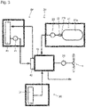
- the flight vehicle is configured to drive the propellers by electric power generated by the fuel cell, thereby obtaining power necessary for flight. Therefore, as can be seen in Fig. 3 , the fuel cell 10 is electrically connected to a motor to drive the propellers (motor for propellers 50), and the propellers 4 are driven by this motor to drive the propellers (motor for propellers 50). Hydrogen from a hydrogen supply system 20 and air from an air supply system 30 are supplied to the fuel cell 10, whereby the fuel cell 10 generates electricity. Cooling water is supplied from a circulating cooling water system 40 to the fuel cell 10, to cool the fuel cell 10.
- the fuel cell 10 is as is known.
- the fuel cell 10 is formed by housing a fuel cell stack of plural stacked fuel cells in a case for a stack.
- the plural fuel cells are each formed of a membrane-electrode assembly (MEA) held between two separators.
- MEA membrane-electrode assembly
- the MEA is a layered product of a solid polymer membrane, an anode catalyst layer, a cathode catalyst layer, an anode gas diffusion layer, a cathode gas diffusion layer, etc.
- the hydrogen supply system 20 is a system supplying hydrogen to the fuel cell 10 via piping.
- the hydrogen supply system 20 is as is known, and is provided with a hydrogen tank 21, a valve 22 and a hydrogen pump 23.
- the hydrogen tank 21 is a tank in which hydrogen is stored, and is provided with a hydrogen tank body 21a in the form of a container, and a mouthpiece 21b whereby hydrogen stored in the hydrogen tank body 21a is taken out via the mouthpiece 21b.
- the valve 22 is attached to the mouthpiece 21b for controlling the hydrogen so that the hydrogen enters or exits the hydrogen tank 21.
- the hydrogen pump 23 is a pump by which the hydrogen taken out of the hydrogen tank 21 via the valve 22 is fed to the fuel cell 10.
- the specific aspect of the hydrogen pump 23 is not particularly limited. A known hydrogen pump applied to a power generation system by a fuel cell may be applied to the hydrogen pump 23.
- the air supply system 30 is a system supplying air to the fuel cell 10 via piping.
- the air supply system 30 is as is known, and is provided with an air compressor 31.
- the air compressor 31 takes in and compresses ambient air, to feed the air to the fuel cell 10.
- the specific aspect of the air compressor 31 is not particularly limited. A known air compressor applied to a power generation system by a fuel cell may be applied to the air compressor 31.
- the circulating cooling water system 40 circulates cooling water via piping to supply the cooling water to the fuel cell 10 and collect the cooling water that has cooled the fuel cell 10, to emit heat to the outside air.
- the circulating cooling water system 40 is as is known, and is provided with a cooling water pump 41, a heat exchanger for cooling 42, and a radiator 43.
- the cooling water pump 41 is a pump by which cooling water is circulated. A known one may be used.
- the heat exchanger for cooling 42 is disposed on the fuel cell 10.
- the heat exchanger 42 absorbs the heat caused by the generation of electricity by the fuel cell 10, thereby cooling the fuel cell 10.
- the specific aspect of the heat exchanger for cooling 42 is not particularly limited.
- a known heat exchanger for cooling which is applied to a power generation system by a fuel cell may be applied to the heat exchanger 42.
- the radiator 43 is a heat exchanger from which the heat absorbed from the fuel cell 10 is radiated to the outside air. According to the foregoing, the heat from the cooling water including the heat absorbed from the fuel cell 10 is emitted to the outside air, so that the cooling water can cool the fuel cell 10 again.
- the specific aspect of the radiator 43 is not particularly limited. A known radiator applied to a power generation system by a fuel cell may be applied to the radiator 43.
- cooling water passes through each structure via the piping, to circulate as follows.
- the cooling water arriving at the heat exchanger for cooling 42 by means of the cooling water pump 41 absorbs the heat from the fuel cell 10, and moves to the radiator 43.
- the cooling water arriving at the radiator 43 emits the heat absorbed from the fuel cell 10 to the outside air, and reaches the cooling water pump 41 again.
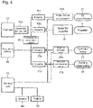
- Fig. 4 schematically shows the relationship among the structures driven using the electric power generated by the fuel cell 10.
- the propellers 4 are driven by the motor for propellers 50, using the electric power generated by the fuel cell 10 via a converter for a fuel cell 10a, and an inverter 50a. Power for flight is obtained by driving the propellers 4.
- the cooling water pump 41 is driven by a motor for a cooling water pump 41b, using the electric power generated by the fuel cell 10 via the converter for a fuel cell 10a, and an inverter 41a.
- the cooling water pump 41 is driven, whereby cooling water circulates through the circulating cooling water system 40 as described above.
- the air compressor 31 is driven by a motor for an air compressor 31b, using the electric power generated by the fuel cell 10 via the converter for a fuel cell 10a, and an inverter 31a.
- the air compressor 31 is driven, whereby air is supplied from the air supply system 30 to the fuel cell 10 as described above.
- the hydrogen pump 23 is driven by a motor for a hydrogen pump 23b, using the electric power generated by the fuel cell 10 via the converter for a fuel cell 10a, and an inverter 23a.
- the hydrogen pump 23 is driven, whereby hydrogen is supplied from the hydrogen supply system 20 to the fuel cell 10 as described above.
- An electric system for the driving with the generated electricity includes a secondary battery 60 provided in the flight vehicle 1.
- the secondary battery 60 is also electrically connected to each of the motor for an air compressor 31b, the motor for propellers 50, the motor for a cooling water pump 41b, and the motor for a hydrogen pump 23b via a secondary battery converter 61 and/or the inverters 23a, 31a, 41a and 50a, so that the foregoing structures can be driven.
- Electric power is supplied by the secondary battery 60 when the aircraft 1 is started, and other than this, may be also supplied in case of emergency.
- the secondary battery 60 is made so as to be able to be charged with the electric power from the fuel cell 10.
- Fig. 4 shows the configuration concerning the stop control of the fuel cell, together with the relationship among the structures driven using the electric power generated by the fuel cell 10.
- the flight vehicle 1 is provided with a control unit 70 and a sensor 80, for the stop control of the fuel cell 10.
- the sensor 80 is disposed on the leg part 5 of the aircraft 1, and is a sensor detecting a load applied to the leg part 5. That is, the sensor 80 detects the load of the body 2 etc. applied to the leg part 5 when the aircraft 1 lands.
- the number of the disposed sensor(s) 80 may be either one or more than two. When the number of the leg parts 5 are more than two, the sensor(s) may be disposed on each or any one of the leg parts 5.
- the specific aspect of the sensor 80 is not particularly limited.
- Examples of the sensor 80 include a load sensor, a strain sensor, and a sensor in combination of a spring and a sensor detecting the degree of stretching or compressing of the spring (for example, in combination of a spring and an optical sensor).
- control unit 70 determines whether to stop the fuel cell 10 or not, in response to the instruction from the stop switch 90, based on information from the sensor 80, to carry out the stop control of the fuel cell 10. Therefore, as shown in Fig. 4 , the control unit 70 is electrically connected to the stop switch 90, the sensor 80, the motor for an air compressor 31b, and the motor for a hydrogen pump 23b.
- control unit 70 is a computer.
- Fig. 5 schematically shows the configuration of the control unit 70 according to one example.
- the control unit 70 includes an operator 71, RAM 72, a storage unit 73, a receiving unit 74, and an output unit 75.
- the operator 71 is configured by so-called CPU (central operator), executes various programs stored in the storage unit 73 etc. that function as storage media, perform operation based on the information from the stop switch 90 and the sensor 80, and transmits instructions to the motor for an air compressor 31b and the motor for a hydrogen pump 23b.
- CPU central operator
- the RAM 72 is a component functioning as a workspace for the operator, and a storage unit for temporary data.
- the RAM may be configured by SRAM, DRAM, flash memory, or the like, and is the same as known RAM.
- the storage unit 73 is a member functioning as a storage medium in which programs and data which are the bases of various operations are stored. In the storage unit, various intermediate and final results obtained by executing programs may be stored.
- the program as follows is included as one program stored in this storage unit 73: a program to perform operation based on the information from the stop switch 90 and the sensor 80, and transmit instructions to the motor for an air compressor 31b and the motor for a hydrogen pump 23b, to carry out the control of stopping the generation of electricity by the fuel cell 10, as described later.
- the receiving unit 74 is a component having a function of receiving the signals from the stop switch 90 and the sensor 80.
- the output unit 75 is a component having a function of suitably outputting information that is to be output to the outside among the obtained results.
- the motor for an air compressor 31b and the motor for a hydrogen pump 23b are electrically connected to the output unit 75.
- Figs. 6 to 9 show the flows of four embodiments.
- operation with the control unit 70 according to the first embodiment includes Steps S11 to S13. Each of the steps will be described below.
- Step S11 it is detected that the stop switch 90 is operated.
- Step S12 it is determined whether the load applied to the leg part 5 is more than a threshold value, based on a signal from the sensor 80.
- the threshold value the amount of the load detected by the sensor 80 in the state where the aircraft 1 lands is obtained in advance, and is stored in the storage unit 73 as a database.
- Step S12 If the result is No in Step S12, it is determined that the aircraft 1 does not land, and the generation of electricity by the fuel cell 10 is maintained without stopping thereof. The operation of the stop switch 90 is canceled.
- Step S12 If the result is Yes in Step S12, it is determined that the aircraft 1 lands, and the process moves to Step S13.
- Step S13 stopping of the fuel cell 10 is carried out.
- the stopping of the fuel cell 10 is performed by: transmitting a signal from the control unit 70 to the motor for an air compressor 31b and/or the motor for a hydrogen pump 23b to stop the motor(s) 31b and/or 23b.
- the motor for an air compressor 31b and/or the motor for a hydrogen pump 23b is/are actually stopped after water is drained, gas is set (air is sealed in; and the pressure of hydrogen is set), and a main valve is closed. According to the above, prevention of the fuel cell from deteriorating, and a smooth restart (antifreezing) of the fuel cell are achieved.
- the fuel cell 10 is stopped after it is determined that the aircraft 1 lands based on the determination of the load applied to the leg part 5.
- the generation of electricity by the fuel cell 10 is not stopped even when the stop switch 90 is mistakenly operated in flight.
- operation with the control unit 70 according to the second embodiment includes Steps S21 to S23. Each of the steps will be described below.
- Step S21 it is detected that the stop switch 90 is operated.
- Step S22 it is determined whether respective loads detected by all the sensors are more than a threshold value, based on signals from a plurality of the disposed sensors 80.
- the threshold value the amounts of the loads detected by the sensors 80 in the state where the aircraft 1 lands are each obtained in advance, and are stored in the storage unit 73 as a database.
- Step S22 If the result is No in Step S22, it is determined that the aircraft 1 does not land, and the generation of electricity by the fuel cell 10 is maintained without stopping thereof. The operation of the stop switch is canceled.
- Step S22 If the result is Yes in Step S22, it is determined that the aircraft 1 lands, and the process moves to Step S23.
- Step S23 stopping of the fuel cell 10 is carried out.
- the stopping of the fuel cell 10 is performed by: transmitting a signal from the control unit 70 to the motor for an air compressor 31b and/or the motor for a hydrogen pump 23b to stop the motor(s) 31b and/or 23b.
- the motor for an air compressor 31b and/or the motor for a hydrogen pump 23b is/are actually stopped after water is drained, gas is set (air is sealed in; and the pressure of hydrogen is set), and a main valve is closed. According to the above, prevention of the fuel cell from deteriorating, and a smooth restart (antifreezing) of the fuel cell are achieved.
- the fuel cell 10 is stopped after it is determined that the aircraft 1 lands based on the determination of the load applied to the leg part 5.
- the generation of electricity by the fuel cell 10 is not stopped even when the stop switch 90 is mistakenly operated in flight.
- whether the aircraft 1 lands or not can be more reliably determined because all the respective loads detected by a plurality of the disposed sensors 80 are required to each exceed the threshold value.
- operation with the control unit 70 according to the third embodiment includes Steps S31 to S36. Each of the steps will be described below.
- Step S31 it is detected that the stop switch 90 is operated.
- Step S32 it is determined whether the load is more than a threshold value, based on a signal from the sensor 80.
- the threshold value the amount of the load detected by the sensor 80 in the state where the aircraft 1 lands is obtained in advance, and is stored in the storage unit 73 as a database.
- Step S32 If the result is No in Step S32, it is determined that the aircraft 1 does not land, and the generation of electricity by the fuel cell 10 is maintained without stopping thereof. The operation of the stop switch is canceled.
- Step S32 If the result is Yes in Step S32, the process moves to Step S33.
- Step S33 predetermined time is measured. After this time has elapsed, the process moves to Step S34.
- Step S34 it is determined whether the load to the leg part, which is obtained in Step S32, is still maintained even after the time measured in Step S33 has elapsed.
- Step S34 If the result is No in Step S34, it is determined that the load to the leg part 5 is temporary and the aircraft 1 does not land, and the process moves to Step S36.
- Step S36 the measuring of the time in Step S33 is cleared, and the generation of electricity by the fuel cell 10 is maintained without stopping thereof. The operation of the stop switch is canceled.
- Step S34 If the result is Yes in Step S34, the process moves to Step S35.
- Step S35 stopping of the fuel cell 10 is carried out.
- the stopping of the fuel cell 10 is performed by: transmitting a signal from the control unit 70 to the motor for an air compressor 31b and/or the motor for a hydrogen pump 23b to stop the motor(s) 31b and/or 23b.
- the motor for an air compressor 31b and/or the motor for a hydrogen pump 23b is/are actually stopped after water is drained, gas is set (air is sealed in; and the pressure of hydrogen is set), and a main valve is closed. According to the above, prevention of the fuel cell from deteriorating, and a smooth restart (antifreezing) of the fuel cell are achieved.
- the fuel cell is stopped after it is determined that the aircraft 1 lands based on the determination of the load applied to the leg part 5.
- the generation of electricity by the fuel cell is not stopped even when the stop switch 90 is mistakenly operated in flight.
- the stopping of the fuel cell is not performed unless the load applied to the leg part is maintained even after some period of time has elapsed, even once the load exceeds the threshold value.
- it can be prevented to stop the fuel cell when a temporary load to the leg part is detected for some reason although the aircraft does not land, and it can be more reliably prevented to stop the generation of electricity by the fuel cell by mistake.
- operation with the control unit 70 according to the fourth embodiment includes Steps S41 to S46. Each of the steps will be described below.
- Step S41 the load is detected by the sensor 80, and a signal is transmitted to the control unit 70. This transmission is performed automatically at predetermined time intervals.
- Step S42 it is determined whether the load is more than a threshold value, based on the signal from the sensor 80 which is obtained in Step S41.
- the threshold value the amount of the load detected by the sensor 80 in the state where the aircraft 1 lands is obtained in advance, and is stored in the storage unit 73 as a database.
- Step S42 If the result is No in Step S42, it is determined that the aircraft 1 does not land, and the process moves to Step S46. In Step S46, the operation of the stop switch 90 is inhibited.
- Step S42 If the result is Yes in Step S42, the process moves to Step S43.
- Step S43 the operation of the stop switch 90 is permitted, and the process moves to Step S44.
- Step S44 a pilot operates the stop switch 90, and it is detected that the stop switch 90 is operated. Then, the process moves to Step S45.
- Step S45 stopping of the fuel cell 10 is carried out.
- the stopping of the fuel cell 10 is performed by: transmitting a signal from the control unit 70 to the motor for an air compressor 31b and/or the motor for a hydrogen pump 23b to stop the motor(s) 31b and/or 23b.
- the motor for an air compressor 31b and/or the motor for a hydrogen pump 23b is/are actually stopped after water is drained, gas is set (air is sealed in; and the pressure of hydrogen is set), and a main valve is closed. According to the above, prevention of the fuel cell from deteriorating, and a smooth restart (antifreezing) of the fuel cell are achieved.
- the operation of the stop switch 90 is permitted after it is determined that the aircraft 1 lands based on the determination of the load applied to the leg part 5.
- no mistaken operation is conducted, and the generation of electricity by the fuel cell is not stopped either because the operation of the stop switch 90 is inhibited in flight. That is, in this embodiment, the operation of the stop switch 90 itself is inhibited unless it is determined that the aircraft 1 lands.
Landscapes
- Engineering & Computer Science (AREA)
- Aviation & Aerospace Engineering (AREA)
- Life Sciences & Earth Sciences (AREA)
- Sustainable Development (AREA)
- Sustainable Energy (AREA)
- Mechanical Engineering (AREA)
- Transportation (AREA)
- Power Engineering (AREA)
- Manufacturing & Machinery (AREA)
- Chemical & Material Sciences (AREA)
- Chemical Kinetics & Catalysis (AREA)
- Electrochemistry (AREA)
- General Chemical & Material Sciences (AREA)
- Fuel Cell (AREA)
Abstract
Description
- The present disclosure relates to a flight vehicle.
- In an aircraft that flies with an engine using jet fuel as a power source, for example, Patent Literature 1 discloses a method and an apparatus for controlling a fuel flow to an engine, and
Patent Literature 2 discloses automatic control systems for aircraft auxiliary power units, and associated methods. -
- Patent Literature 1:
JP 2007-511701 A - Patent Literature 2:
JP 2008-514485 A - When generation of electricity is stopped by the operation of stopping the generation of electricity by a fuel cell (such as a stop operation of a switch) in flight in a flight vehicle using the fuel cell as a power source for flight, power for generating thrust is lost. Once the generation of electricity by a fuel cell is stopped, it takes more time to restart the generation than that by an engine, and in some cases, it may be impossible to restart the generation due to freezing.
- An object of the present disclosure is to provide a flight vehicle that makes it possible to prevent the generation of electricity by a fuel cell from being stopped in flight even when a mistaken operation is conducted.
- The present application discloses a flight vehicle including a fuel cell and a propeller, the propeller to be driven by electric power generated by the fuel cell, the flight vehicle comprising: a stop device giving an instruction to stop the generation of electricity by the fuel cell; a control unit processing stopping of the generation of electricity by the fuel cell; a leg part grounding when the flight vehicle lands, to support a load of the flight vehicle; and a sensor detecting the load applied to the leg part, wherein the control unit permits the stopping of the generation of electricity based on signals from the stop device and the sensor only if a predetermined amount of the load is applied to the leg part.
- Here, "the control unit permits the stopping of the generation of electricity based on signals from the stop device and the sensor only if a predetermined amount of the load is applied to the leg part" means at least one of: that the control unit does not process the stopping of the generation of electricity even if the stop device (such as a stop switch) is operated unless the conditions are satisfied; and that the stop device (such as a stop switch) cannot be operated unless the conditions are satisfied.
- A plurality of the sensors may be disposed on the leg part, and the control unit may permit the stopping of the generation of electricity only if all the respective sensors detect that the predetermined amount of the load is applied.
- The control unit may perform the stopping of the generation of electricity after confirming that the predetermined amount of the load is maintained for a predetermine time after each of the sensor(s) has detected that the predetermined amount of the load is applied.
- The flight vehicle according to the present disclosure makes it possible to prevent the generation of electricity by a fuel cell from being stopped in flight even when a mistaken operation is conducted.
-
-
Fig. 1 shows an external appearance of a flight vehicle (aircraft 1); -
Fig. 2 shows acontrol panel 3a; -
Fig. 3 is a conceptual view explanatorily showing a configuration for the generation of electricity by afuel cell 10; -
Fig. 4 is a conceptual view explanatorily showing the relationship among devices driven by thefuel cell 10; -
Fig. 5 explanatorily shows a configuration of thecontrol unit 70; -
Fig. 6 explanatorily shows the flow of stop control according to the first embodiment; -
Fig. 7 explanatorily shows the flow of stop control according to the second embodiment; -
Fig. 8 explanatorily shows the flow of stop control according to the third embodiment; and -
Fig. 9 explanatorily shows the flow of stop control according to the fourth embodiment. -
Figs. 1 to 4 explanatorily show the configuration of a flight vehicle (aircraft 1) with a fuel cell as a power source for flight which is an example according to one embodiment.Fig. 1 shows an external appearance of this flight vehicle (aircraft 1).Fig. 2 is an external view of acontrol panel 3a provided in a cockpit 3 of the flight vehicle (aircraft 1).Fig. 3 schematically shows the configuration for the generation of electricity by afuel cell 10 which is included in the flight vehicle (aircraft 1).Fig. 4 schematically shows the relationship among structures relating to the operation of thefuel cell 10. - The aircraft I will be described here as one embodiment of a flight vehicle for the description. The scope of the flight vehicle according to the present disclosure may include various embodiments of the flight vehicle as long as a fuel cell is used therein as a power source for a propeller, and the external appearance thereof, the position of the propeller, the number of the propeller(s), etc. are not particularly limited either. Accordingly, the size, the capacity, etc., that is, the scale of the flight vehicle is not limited. The scope of the flight vehicle according to the present disclosure also includes a drone and the like which are unmanned flight vehicles which are wirelessly operated or into which flight routes are programmed in advance, to fly.
- As can be seen in
Fig. 1 , the aircraft 1 according to the present embodiment is provided with abody 2 that is a housing for housing thereinside each component necessary for flight, and a cockpit 3 on an upper portion of thebody 2 which is for a person to get into, to pilot the aircraft 1. On the aircraft 1 according to the present embodiment,propellers 4 for taking-off and propulsion of the aircraft 1 which are four in total are arranged: the fourpropellers 4 are respectively in the left front, right front, left back and right back of thebody 2. Further, aleg part 5 that grounds when the aircraft lands, to support thebody 2 is provided on a lower portion of thebody 2. The number of the leg part(s) 5 may be either one or more as long as the leg part(s) 5 can support thebody 2. - The
control panel 3a is disposed in the cockpit 3 as shown inFig. 2 . A stop switch 90 (stop device to give an instruction to stop the generation of electricity by the fuel cell. In this embodiment, the stop switch is also a switch to start the operation of the fuel cell) is arranged on thecontrol panel 3a. On thecontrol panel 3a,meters 91 are arranged in addition to thestop switch 90. Themeters 91 are not particularly limited, and examples thereof include a speedometer, a gyro horizon, an altimeter, a turn-and-bank indicator, a vertical speed indicator, a tachometer, and a compass. - The flight vehicle according to the present disclosure is configured to drive the propellers by electric power generated by the fuel cell, thereby obtaining power necessary for flight. Therefore, as can be seen in
Fig. 3 , thefuel cell 10 is electrically connected to a motor to drive the propellers (motor for propellers 50), and thepropellers 4 are driven by this motor to drive the propellers (motor for propellers 50). Hydrogen from ahydrogen supply system 20 and air from anair supply system 30 are supplied to thefuel cell 10, whereby thefuel cell 10 generates electricity. Cooling water is supplied from a circulatingcooling water system 40 to thefuel cell 10, to cool thefuel cell 10. Each of the structures will be described below. - The
fuel cell 10 is as is known. For example, thefuel cell 10 is formed by housing a fuel cell stack of plural stacked fuel cells in a case for a stack. The plural fuel cells are each formed of a membrane-electrode assembly (MEA) held between two separators. The MEA is a layered product of a solid polymer membrane, an anode catalyst layer, a cathode catalyst layer, an anode gas diffusion layer, a cathode gas diffusion layer, etc. - The
hydrogen supply system 20 is a system supplying hydrogen to thefuel cell 10 via piping. Thehydrogen supply system 20 is as is known, and is provided with ahydrogen tank 21, avalve 22 and ahydrogen pump 23. - The
hydrogen tank 21 is a tank in which hydrogen is stored, and is provided with ahydrogen tank body 21a in the form of a container, and amouthpiece 21b whereby hydrogen stored in thehydrogen tank body 21a is taken out via themouthpiece 21b. - The
valve 22 is attached to themouthpiece 21b for controlling the hydrogen so that the hydrogen enters or exits thehydrogen tank 21. - The
hydrogen pump 23 is a pump by which the hydrogen taken out of thehydrogen tank 21 via thevalve 22 is fed to thefuel cell 10. The specific aspect of thehydrogen pump 23 is not particularly limited. A known hydrogen pump applied to a power generation system by a fuel cell may be applied to thehydrogen pump 23. - The
air supply system 30 is a system supplying air to thefuel cell 10 via piping. Theair supply system 30 is as is known, and is provided with anair compressor 31. Theair compressor 31 takes in and compresses ambient air, to feed the air to thefuel cell 10. The specific aspect of theair compressor 31 is not particularly limited. A known air compressor applied to a power generation system by a fuel cell may be applied to theair compressor 31. - The circulating
cooling water system 40 circulates cooling water via piping to supply the cooling water to thefuel cell 10 and collect the cooling water that has cooled thefuel cell 10, to emit heat to the outside air. The circulatingcooling water system 40 is as is known, and is provided with a coolingwater pump 41, a heat exchanger for cooling 42, and aradiator 43. - The cooling
water pump 41 is a pump by which cooling water is circulated. A known one may be used. - The heat exchanger for cooling 42 is disposed on the
fuel cell 10. Theheat exchanger 42 absorbs the heat caused by the generation of electricity by thefuel cell 10, thereby cooling thefuel cell 10. The specific aspect of the heat exchanger for cooling 42 is not particularly limited. A known heat exchanger for cooling which is applied to a power generation system by a fuel cell may be applied to theheat exchanger 42. - The
radiator 43 is a heat exchanger from which the heat absorbed from thefuel cell 10 is radiated to the outside air. According to the foregoing, the heat from the cooling water including the heat absorbed from thefuel cell 10 is emitted to the outside air, so that the cooling water can cool thefuel cell 10 again. The specific aspect of theradiator 43 is not particularly limited. A known radiator applied to a power generation system by a fuel cell may be applied to theradiator 43. - With the configuration as described above, cooling water passes through each structure via the piping, to circulate as follows. The cooling water arriving at the heat exchanger for cooling 42 by means of the cooling
water pump 41 absorbs the heat from thefuel cell 10, and moves to theradiator 43. The cooling water arriving at theradiator 43 emits the heat absorbed from thefuel cell 10 to the outside air, and reaches the coolingwater pump 41 again. -
Fig. 4 schematically shows the relationship among the structures driven using the electric power generated by thefuel cell 10. - The
propellers 4 are driven by the motor forpropellers 50, using the electric power generated by thefuel cell 10 via a converter for afuel cell 10a, and an inverter 50a. Power for flight is obtained by driving thepropellers 4. - The cooling
water pump 41 is driven by a motor for acooling water pump 41b, using the electric power generated by thefuel cell 10 via the converter for afuel cell 10a, and aninverter 41a. The coolingwater pump 41 is driven, whereby cooling water circulates through the circulatingcooling water system 40 as described above. - The
air compressor 31 is driven by a motor for anair compressor 31b, using the electric power generated by thefuel cell 10 via the converter for afuel cell 10a, and aninverter 31a. Theair compressor 31 is driven, whereby air is supplied from theair supply system 30 to thefuel cell 10 as described above. - The
hydrogen pump 23 is driven by a motor for ahydrogen pump 23b, using the electric power generated by thefuel cell 10 via the converter for afuel cell 10a, and aninverter 23a. Thehydrogen pump 23 is driven, whereby hydrogen is supplied from thehydrogen supply system 20 to thefuel cell 10 as described above. - An electric system for the driving with the generated electricity includes a
secondary battery 60 provided in the flight vehicle 1. Thesecondary battery 60 is also electrically connected to each of the motor for anair compressor 31b, the motor forpropellers 50, the motor for acooling water pump 41b, and the motor for ahydrogen pump 23b via asecondary battery converter 61 and/or theinverters - Electric power is supplied by the
secondary battery 60 when the aircraft 1 is started, and other than this, may be also supplied in case of emergency. Thesecondary battery 60 is made so as to be able to be charged with the electric power from thefuel cell 10. -
Fig. 4 shows the configuration concerning the stop control of the fuel cell, together with the relationship among the structures driven using the electric power generated by thefuel cell 10. - The flight vehicle 1 is provided with a
control unit 70 and asensor 80, for the stop control of thefuel cell 10. - As schematically shown in
Fig. 1 , for example, thesensor 80 is disposed on theleg part 5 of the aircraft 1, and is a sensor detecting a load applied to theleg part 5. That is, thesensor 80 detects the load of thebody 2 etc. applied to theleg part 5 when the aircraft 1 lands. The number of the disposed sensor(s) 80 may be either one or more than two. When the number of theleg parts 5 are more than two, the sensor(s) may be disposed on each or any one of theleg parts 5. - The specific aspect of the
sensor 80 is not particularly limited. Examples of thesensor 80 include a load sensor, a strain sensor, and a sensor in combination of a spring and a sensor detecting the degree of stretching or compressing of the spring (for example, in combination of a spring and an optical sensor). - As described later, the
control unit 70 determines whether to stop thefuel cell 10 or not, in response to the instruction from thestop switch 90, based on information from thesensor 80, to carry out the stop control of thefuel cell 10. Therefore, as shown inFig. 4 , thecontrol unit 70 is electrically connected to thestop switch 90, thesensor 80, the motor for anair compressor 31b, and the motor for ahydrogen pump 23b. - How to carry out the stop control specifically will be described in detail later.
- An example of the
control unit 70 is a computer.Fig. 5 schematically shows the configuration of thecontrol unit 70 according to one example. Thecontrol unit 70 includes anoperator 71,RAM 72, astorage unit 73, a receivingunit 74, and anoutput unit 75. - The
operator 71 is configured by so-called CPU (central operator), executes various programs stored in thestorage unit 73 etc. that function as storage media, perform operation based on the information from thestop switch 90 and thesensor 80, and transmits instructions to the motor for anair compressor 31b and the motor for ahydrogen pump 23b. - The
RAM 72 is a component functioning as a workspace for the operator, and a storage unit for temporary data. The RAM may be configured by SRAM, DRAM, flash memory, or the like, and is the same as known RAM. - The
storage unit 73 is a member functioning as a storage medium in which programs and data which are the bases of various operations are stored. In the storage unit, various intermediate and final results obtained by executing programs may be stored. - In the present embodiment, the program as follows is included as one program stored in this storage unit 73: a program to perform operation based on the information from the
stop switch 90 and thesensor 80, and transmit instructions to the motor for anair compressor 31b and the motor for ahydrogen pump 23b, to carry out the control of stopping the generation of electricity by thefuel cell 10, as described later. - The receiving
unit 74 is a component having a function of receiving the signals from thestop switch 90 and thesensor 80. - The
output unit 75 is a component having a function of suitably outputting information that is to be output to the outside among the obtained results. In the present embodiment, the motor for anair compressor 31b and the motor for ahydrogen pump 23b are electrically connected to theoutput unit 75. - Next, the stop control of the
fuel cell 10 with thecontrol unit 70 will be described.Figs. 6 to 9 show the flows of four embodiments. - As can be seen from
Fig. 6 , operation with thecontrol unit 70 according to the first embodiment includes Steps S11 to S13. Each of the steps will be described below. - In Step S11, it is detected that the
stop switch 90 is operated. - In Step S12, it is determined whether the load applied to the
leg part 5 is more than a threshold value, based on a signal from thesensor 80. Here, as the threshold value, the amount of the load detected by thesensor 80 in the state where the aircraft 1 lands is obtained in advance, and is stored in thestorage unit 73 as a database. - If the result is No in Step S12, it is determined that the aircraft 1 does not land, and the generation of electricity by the
fuel cell 10 is maintained without stopping thereof. The operation of thestop switch 90 is canceled. - If the result is Yes in Step S12, it is determined that the aircraft 1 lands, and the process moves to Step S13.
- In Step S13, stopping of the
fuel cell 10 is carried out. The stopping of thefuel cell 10 is performed by: transmitting a signal from thecontrol unit 70 to the motor for anair compressor 31b and/or the motor for ahydrogen pump 23b to stop the motor(s) 31b and/or 23b. Preferably, the motor for anair compressor 31b and/or the motor for ahydrogen pump 23b is/are actually stopped after water is drained, gas is set (air is sealed in; and the pressure of hydrogen is set), and a main valve is closed. According to the above, prevention of the fuel cell from deteriorating, and a smooth restart (antifreezing) of the fuel cell are achieved. - According to such stop control of the
fuel cell 10 with thecontrol unit 70, thefuel cell 10 is stopped after it is determined that the aircraft 1 lands based on the determination of the load applied to theleg part 5. Thus, the generation of electricity by thefuel cell 10 is not stopped even when thestop switch 90 is mistakenly operated in flight. - As can be seen from
Fig. 7 , operation with thecontrol unit 70 according to the second embodiment includes Steps S21 to S23. Each of the steps will be described below. - In Step S21, it is detected that the
stop switch 90 is operated. - In Step S22, it is determined whether respective loads detected by all the sensors are more than a threshold value, based on signals from a plurality of the disposed
sensors 80. Here, as the threshold value, the amounts of the loads detected by thesensors 80 in the state where the aircraft 1 lands are each obtained in advance, and are stored in thestorage unit 73 as a database. - If the result is No in Step S22, it is determined that the aircraft 1 does not land, and the generation of electricity by the
fuel cell 10 is maintained without stopping thereof. The operation of the stop switch is canceled. - If the result is Yes in Step S22, it is determined that the aircraft 1 lands, and the process moves to Step S23.
- In Step S23, stopping of the
fuel cell 10 is carried out. The stopping of thefuel cell 10 is performed by: transmitting a signal from thecontrol unit 70 to the motor for anair compressor 31b and/or the motor for ahydrogen pump 23b to stop the motor(s) 31b and/or 23b. Preferably, the motor for anair compressor 31b and/or the motor for ahydrogen pump 23b is/are actually stopped after water is drained, gas is set (air is sealed in; and the pressure of hydrogen is set), and a main valve is closed. According to the above, prevention of the fuel cell from deteriorating, and a smooth restart (antifreezing) of the fuel cell are achieved. - According to such stop control of the
fuel cell 10 with thecontrol unit 70, thefuel cell 10 is stopped after it is determined that the aircraft 1 lands based on the determination of the load applied to theleg part 5. Thus, the generation of electricity by thefuel cell 10 is not stopped even when thestop switch 90 is mistakenly operated in flight. - In this embodiment, whether the aircraft 1 lands or not can be more reliably determined because all the respective loads detected by a plurality of the disposed
sensors 80 are required to each exceed the threshold value. - As can be seen from
Fig. 8 , operation with thecontrol unit 70 according to the third embodiment includes Steps S31 to S36. Each of the steps will be described below. - In Step S31, it is detected that the
stop switch 90 is operated. - In Step S32, it is determined whether the load is more than a threshold value, based on a signal from the
sensor 80. Here, as the threshold value, the amount of the load detected by thesensor 80 in the state where the aircraft 1 lands is obtained in advance, and is stored in thestorage unit 73 as a database. - If the result is No in Step S32, it is determined that the aircraft 1 does not land, and the generation of electricity by the
fuel cell 10 is maintained without stopping thereof. The operation of the stop switch is canceled. - If the result is Yes in Step S32, the process moves to Step S33.
- In Step S33, predetermined time is measured. After this time has elapsed, the process moves to Step S34.
- In Step S34, it is determined whether the load to the leg part, which is obtained in Step S32, is still maintained even after the time measured in Step S33 has elapsed.
- If the result is No in Step S34, it is determined that the load to the
leg part 5 is temporary and the aircraft 1 does not land, and the process moves to Step S36. In Step S36, the measuring of the time in Step S33 is cleared, and the generation of electricity by thefuel cell 10 is maintained without stopping thereof. The operation of the stop switch is canceled. - If the result is Yes in Step S34, the process moves to Step S35.
- In Step S35, stopping of the
fuel cell 10 is carried out. The stopping of thefuel cell 10 is performed by: transmitting a signal from thecontrol unit 70 to the motor for anair compressor 31b and/or the motor for ahydrogen pump 23b to stop the motor(s) 31b and/or 23b. Preferably, the motor for anair compressor 31b and/or the motor for ahydrogen pump 23b is/are actually stopped after water is drained, gas is set (air is sealed in; and the pressure of hydrogen is set), and a main valve is closed. According to the above, prevention of the fuel cell from deteriorating, and a smooth restart (antifreezing) of the fuel cell are achieved. - According to such stop control of the
fuel cell 10 with thecontrol unit 70, the fuel cell is stopped after it is determined that the aircraft 1 lands based on the determination of the load applied to theleg part 5. Thus, the generation of electricity by the fuel cell is not stopped even when thestop switch 90 is mistakenly operated in flight. - In this embodiment, the stopping of the fuel cell is not performed unless the load applied to the leg part is maintained even after some period of time has elapsed, even once the load exceeds the threshold value. Thus, it can be prevented to stop the fuel cell when a temporary load to the leg part is detected for some reason although the aircraft does not land, and it can be more reliably prevented to stop the generation of electricity by the fuel cell by mistake.
- As can be seen from
Fig. 9 , operation with thecontrol unit 70 according to the fourth embodiment includes Steps S41 to S46. Each of the steps will be described below. - In Step S41, the load is detected by the
sensor 80, and a signal is transmitted to thecontrol unit 70. This transmission is performed automatically at predetermined time intervals. - In Step S42, it is determined whether the load is more than a threshold value, based on the signal from the
sensor 80 which is obtained in Step S41. Here, as the threshold value, the amount of the load detected by thesensor 80 in the state where the aircraft 1 lands is obtained in advance, and is stored in thestorage unit 73 as a database. - If the result is No in Step S42, it is determined that the aircraft 1 does not land, and the process moves to Step S46. In Step S46, the operation of the
stop switch 90 is inhibited. - If the result is Yes in Step S42, the process moves to Step S43. In Step S43, the operation of the
stop switch 90 is permitted, and the process moves to Step S44. - In the Step S44, a pilot operates the
stop switch 90, and it is detected that thestop switch 90 is operated. Then, the process moves to Step S45. - In Step S45, stopping of the
fuel cell 10 is carried out. The stopping of thefuel cell 10 is performed by: transmitting a signal from thecontrol unit 70 to the motor for anair compressor 31b and/or the motor for ahydrogen pump 23b to stop the motor(s) 31b and/or 23b. Preferably, the motor for anair compressor 31b and/or the motor for ahydrogen pump 23b is/are actually stopped after water is drained, gas is set (air is sealed in; and the pressure of hydrogen is set), and a main valve is closed. According to the above, prevention of the fuel cell from deteriorating, and a smooth restart (antifreezing) of the fuel cell are achieved. - According to such stop control of the
fuel cell 10 with thecontrol unit 70, the operation of thestop switch 90 is permitted after it is determined that the aircraft 1 lands based on the determination of the load applied to theleg part 5. Thus, no mistaken operation is conducted, and the generation of electricity by the fuel cell is not stopped either because the operation of thestop switch 90 is inhibited in flight. That is, in this embodiment, the operation of thestop switch 90 itself is inhibited unless it is determined that the aircraft 1 lands. -
- 1 aircraft (flight vehicle)
- 2 body
- 3 cockpit
- 4 propeller
- 5 leg part
- 10 fuel cell
- 20 hydrogen supply system
- 21 hydrogen tank
- 22 valve
- 23 hydrogen pump
- 30 air supply system
- 31 air compressor
- 40 circulating cooling water system-
- 41 cooling water pump
- 42 heat exchanger for cooling
- 43 radiator
- 50 motor for a propeller
- 70 control unit
- 80 sensor
- 90 stop switch
Claims (3)
- A flight vehicle including a fuel cell and a propeller, the propeller to be driven by electric power generated by the fuel cell, the flight vehicle comprising:a stop device giving an instruction to stop the generation of electricity by the fuel cell;a control unit processing stopping of the generation of electricity by the fuel cell;a leg part grounding when the flight vehicle lands, to support a load of the flight vehicle; anda sensor detecting the load applied to the leg part, whereinthe control unit permits the stopping of the generation of electricity based on signals from the stop device and the sensor only if a predetermined amount of the load is applied to the leg part.
- The flight vehicle according to claim 1, whereina plurality of the sensors are disposed on the leg part, andthe control unit permits the stopping of the generation of electricity only if all the respective sensors detect that the predetermined amount of the load is applied.
- The flight vehicle according to claim 1 or 2, wherein
the control unit performs the stopping of the generation of electricity after confirming that the predetermined amount of the load is maintained for a predetermine time after each of the sensor(s) has detected that the predetermined amount of the load is applied.
Applications Claiming Priority (1)
| Application Number | Priority Date | Filing Date | Title |
|---|---|---|---|
| JP2021074374A JP7533339B2 (en) | 2021-04-26 | 2021-04-26 | Aircraft |
Publications (2)
| Publication Number | Publication Date |
|---|---|
| EP4082913A1 true EP4082913A1 (en) | 2022-11-02 |
| EP4082913B1 EP4082913B1 (en) | 2024-05-08 |
Family
ID=81384868
Family Applications (1)
| Application Number | Title | Priority Date | Filing Date |
|---|---|---|---|
| EP22166958.3A Active EP4082913B1 (en) | 2021-04-26 | 2022-04-06 | Flight vehicle |
Country Status (4)
| Country | Link |
|---|---|
| US (1) | US20220344680A1 (en) |
| EP (1) | EP4082913B1 (en) |
| JP (1) | JP7533339B2 (en) |
| CN (1) | CN115246484B (en) |
Families Citing this family (1)
| Publication number | Priority date | Publication date | Assignee | Title |
|---|---|---|---|---|
| US20240409224A1 (en) * | 2023-06-09 | 2024-12-12 | Pratt & Whitney Canada Corp. | Electric aircraft engine and compressor for engine retrofit |
Citations (5)
| Publication number | Priority date | Publication date | Assignee | Title |
|---|---|---|---|---|
| JP2007511701A (en) | 2003-11-21 | 2007-05-10 | プラット アンド ホイットニー カナダ コーポレイション | Method and apparatus for controlling fuel flow to an engine |
| JP2008514485A (en) | 2004-09-27 | 2008-05-08 | ザ・ボーイング・カンパニー | Automatic control system and associated method for an aircraft auxiliary power unit |
| US20170200961A1 (en) * | 2015-07-06 | 2017-07-13 | SZ DJI Technology Co., Ltd. | Systems and methods for uav fuel cell |
| WO2020045995A1 (en) * | 2018-08-31 | 2020-03-05 | (주)두산 모빌리티 이노베이션 | Fuel cell power pack-integrated drone |
| US20210009280A1 (en) * | 2019-07-12 | 2021-01-14 | Airbus Sas | Electricity production system for an aircraft, comprising a fuel cell |
Family Cites Families (10)
| Publication number | Priority date | Publication date | Assignee | Title |
|---|---|---|---|---|
| JP2015101198A (en) * | 2013-11-25 | 2015-06-04 | トヨタ自動車株式会社 | Moving body |
| US9799151B2 (en) * | 2015-05-01 | 2017-10-24 | Carolyn J. Olson | Aircraft fuel shutoff interlock |
| JP6183414B2 (en) * | 2015-06-24 | 2017-08-23 | トヨタ自動車株式会社 | Fuel cell system |
| US10732023B2 (en) * | 2016-03-24 | 2020-08-04 | Sikorsky Aircraft Corporation | Measurement system for aircraft, aircraft having the same, and method of measuring weight for aircraft |
| KR102049642B1 (en) * | 2017-11-24 | 2019-11-27 | (주)두산 모빌리티 이노베이션 | Fuel cell powerpack for drone, and state information monitoring method thereof |
| WO2019189075A1 (en) * | 2018-03-28 | 2019-10-03 | 株式会社ナイルワークス | Unmanned aerial vehicle |
| JP7057264B2 (en) * | 2018-11-02 | 2022-04-19 | 本田技研工業株式会社 | Hybrid flying object |
| US10787255B2 (en) * | 2018-11-30 | 2020-09-29 | Sky Canoe Inc. | Aerial vehicle with enhanced pitch control and interchangeable components |
| JP7103246B2 (en) * | 2019-01-30 | 2022-07-20 | トヨタ自動車株式会社 | Fuel cell system and fuel cell system control method |
| JP7160013B2 (en) * | 2019-10-08 | 2022-10-25 | トヨタ自動車株式会社 | Fuel cell system installed in a vehicle |
-
2021
- 2021-04-26 JP JP2021074374A patent/JP7533339B2/en active Active
-
2022
- 2022-03-29 CN CN202210318158.8A patent/CN115246484B/en active Active
- 2022-04-06 EP EP22166958.3A patent/EP4082913B1/en active Active
- 2022-04-12 US US17/659,002 patent/US20220344680A1/en active Pending
Patent Citations (5)
| Publication number | Priority date | Publication date | Assignee | Title |
|---|---|---|---|---|
| JP2007511701A (en) | 2003-11-21 | 2007-05-10 | プラット アンド ホイットニー カナダ コーポレイション | Method and apparatus for controlling fuel flow to an engine |
| JP2008514485A (en) | 2004-09-27 | 2008-05-08 | ザ・ボーイング・カンパニー | Automatic control system and associated method for an aircraft auxiliary power unit |
| US20170200961A1 (en) * | 2015-07-06 | 2017-07-13 | SZ DJI Technology Co., Ltd. | Systems and methods for uav fuel cell |
| WO2020045995A1 (en) * | 2018-08-31 | 2020-03-05 | (주)두산 모빌리티 이노베이션 | Fuel cell power pack-integrated drone |
| US20210009280A1 (en) * | 2019-07-12 | 2021-01-14 | Airbus Sas | Electricity production system for an aircraft, comprising a fuel cell |
Also Published As
| Publication number | Publication date |
|---|---|
| JP7533339B2 (en) | 2024-08-14 |
| US20220344680A1 (en) | 2022-10-27 |
| JP2022168713A (en) | 2022-11-08 |
| CN115246484A (en) | 2022-10-28 |
| EP4082913B1 (en) | 2024-05-08 |
| CN115246484B (en) | 2025-10-17 |
Similar Documents
| Publication | Publication Date | Title |
|---|---|---|
| EP4232363B1 (en) | Aircraft electrical power supply system and method of supplying electrical power in an aircraft | |
| EP3344545B1 (en) | A vehicle comprising an engine restart system | |
| US20220052361A1 (en) | Fuel cell oxygen delivery system, method and apparatus for clean fuel electric aircraft | |
| US20220289379A1 (en) | Mobile emergency power generation and vehicle propulsion power system | |
| US10899466B2 (en) | Electrical power supply on a vehicle | |
| US10040569B2 (en) | Autonomous aircraft fuel cell system | |
| US20120221157A1 (en) | Low pressure spool emergency generator | |
| US20240039022A1 (en) | Power supply control system, power supply control method, and storage medium | |
| US20220340291A1 (en) | Flight vehicle | |
| GB2491982A (en) | Aircraft emergency power system incorporating a fuel cell | |
| CN113752916B (en) | Power supply control system, power supply control method, and storage medium | |
| US20220315223A1 (en) | Mobile emergency communication and vehicle propulsion power system | |
| EP4082914A1 (en) | Flight vehicle | |
| Rathke et al. | Antares DLR-H2–flying test bed for development of aircraft fuel cell systems | |
| EP4082913B1 (en) | Flight vehicle | |
| EP2492451A2 (en) | Low pressure spool emergency generator | |
| US20230369616A1 (en) | Detecting a fault condition in a fuel cell system | |
| US11745881B2 (en) | Fuel cell stack array | |
| Gavrilovic et al. | Flight Testing of a Hydrogen Powered Unmanned Aerial System | |
| Nikola et al. | Flight Testing of a Hydrogen Powered Unmanned Aerial System | |
| US20250058638A1 (en) | Hydrogen fuel cell powered autonomous underwater vehicle | |
| US20230264824A1 (en) | Electric flying vehicle with multiple independent propulsion modules | |
| US11831052B2 (en) | Electric power supply system, controlling method of electric power supply system, and storage medium | |
| KR20250083350A (en) | Liquid hydrogen drone fuel remaining notification system and its control method | |
| JP2025152692A (en) | Operation control device |
Legal Events
| Date | Code | Title | Description |
|---|---|---|---|
| PUAI | Public reference made under article 153(3) epc to a published international application that has entered the european phase |
Free format text: ORIGINAL CODE: 0009012 |
|
| STAA | Information on the status of an ep patent application or granted ep patent |
Free format text: STATUS: REQUEST FOR EXAMINATION WAS MADE |
|
| 17P | Request for examination filed |
Effective date: 20220406 |
|
| AK | Designated contracting states |
Kind code of ref document: A1 Designated state(s): AL AT BE BG CH CY CZ DE DK EE ES FI FR GB GR HR HU IE IS IT LI LT LU LV MC MK MT NL NO PL PT RO RS SE SI SK SM TR |
|
| GRAP | Despatch of communication of intention to grant a patent |
Free format text: ORIGINAL CODE: EPIDOSNIGR1 |
|
| STAA | Information on the status of an ep patent application or granted ep patent |
Free format text: STATUS: GRANT OF PATENT IS INTENDED |
|
| RIC1 | Information provided on ipc code assigned before grant |
Ipc: B64D 41/00 20060101ALN20240221BHEP Ipc: B64C 25/06 20060101ALI20240221BHEP Ipc: B64D 27/24 20060101AFI20240221BHEP |
|
| GRAS | Grant fee paid |
Free format text: ORIGINAL CODE: EPIDOSNIGR3 |
|
| INTG | Intention to grant announced |
Effective date: 20240307 |
|
| GRAA | (expected) grant |
Free format text: ORIGINAL CODE: 0009210 |
|
| STAA | Information on the status of an ep patent application or granted ep patent |
Free format text: STATUS: THE PATENT HAS BEEN GRANTED |
|
| AK | Designated contracting states |
Kind code of ref document: B1 Designated state(s): AL AT BE BG CH CY CZ DE DK EE ES FI FR GB GR HR HU IE IS IT LI LT LU LV MC MK MT NL NO PL PT RO RS SE SI SK SM TR |
|
| REG | Reference to a national code |
Ref country code: GB Ref legal event code: FG4D |
|
| REG | Reference to a national code |
Ref country code: CH Ref legal event code: EP |
|
| REG | Reference to a national code |
Ref country code: DE Ref legal event code: R096 Ref document number: 602022003287 Country of ref document: DE |
|
| REG | Reference to a national code |
Ref country code: IE Ref legal event code: FG4D |
|
| REG | Reference to a national code |
Ref country code: LT Ref legal event code: MG9D |
|
| REG | Reference to a national code |
Ref country code: NL Ref legal event code: MP Effective date: 20240508 |
|
| PG25 | Lapsed in a contracting state [announced via postgrant information from national office to epo] |
Ref country code: IS Free format text: LAPSE BECAUSE OF FAILURE TO SUBMIT A TRANSLATION OF THE DESCRIPTION OR TO PAY THE FEE WITHIN THE PRESCRIBED TIME-LIMIT Effective date: 20240908 |
|
| PG25 | Lapsed in a contracting state [announced via postgrant information from national office to epo] |
Ref country code: BG Free format text: LAPSE BECAUSE OF FAILURE TO SUBMIT A TRANSLATION OF THE DESCRIPTION OR TO PAY THE FEE WITHIN THE PRESCRIBED TIME-LIMIT Effective date: 20240508 |
|
| PG25 | Lapsed in a contracting state [announced via postgrant information from national office to epo] |
Ref country code: FI Free format text: LAPSE BECAUSE OF FAILURE TO SUBMIT A TRANSLATION OF THE DESCRIPTION OR TO PAY THE FEE WITHIN THE PRESCRIBED TIME-LIMIT Effective date: 20240508 Ref country code: HR Free format text: LAPSE BECAUSE OF FAILURE TO SUBMIT A TRANSLATION OF THE DESCRIPTION OR TO PAY THE FEE WITHIN THE PRESCRIBED TIME-LIMIT Effective date: 20240508 |
|
| PG25 | Lapsed in a contracting state [announced via postgrant information from national office to epo] |
Ref country code: GR Free format text: LAPSE BECAUSE OF FAILURE TO SUBMIT A TRANSLATION OF THE DESCRIPTION OR TO PAY THE FEE WITHIN THE PRESCRIBED TIME-LIMIT Effective date: 20240809 |
|
| PG25 | Lapsed in a contracting state [announced via postgrant information from national office to epo] |
Ref country code: PT Free format text: LAPSE BECAUSE OF FAILURE TO SUBMIT A TRANSLATION OF THE DESCRIPTION OR TO PAY THE FEE WITHIN THE PRESCRIBED TIME-LIMIT Effective date: 20240909 |
|
| REG | Reference to a national code |
Ref country code: AT Ref legal event code: MK05 Ref document number: 1684816 Country of ref document: AT Kind code of ref document: T Effective date: 20240508 |
|
| PG25 | Lapsed in a contracting state [announced via postgrant information from national office to epo] |
Ref country code: NL Free format text: LAPSE BECAUSE OF FAILURE TO SUBMIT A TRANSLATION OF THE DESCRIPTION OR TO PAY THE FEE WITHIN THE PRESCRIBED TIME-LIMIT Effective date: 20240508 |
|
| PG25 | Lapsed in a contracting state [announced via postgrant information from national office to epo] |
Ref country code: ES Free format text: LAPSE BECAUSE OF FAILURE TO SUBMIT A TRANSLATION OF THE DESCRIPTION OR TO PAY THE FEE WITHIN THE PRESCRIBED TIME-LIMIT Effective date: 20240508 |
|
| PG25 | Lapsed in a contracting state [announced via postgrant information from national office to epo] |
Ref country code: AT Free format text: LAPSE BECAUSE OF FAILURE TO SUBMIT A TRANSLATION OF THE DESCRIPTION OR TO PAY THE FEE WITHIN THE PRESCRIBED TIME-LIMIT Effective date: 20240508 |
|
| PG25 | Lapsed in a contracting state [announced via postgrant information from national office to epo] |
Ref country code: PL Free format text: LAPSE BECAUSE OF FAILURE TO SUBMIT A TRANSLATION OF THE DESCRIPTION OR TO PAY THE FEE WITHIN THE PRESCRIBED TIME-LIMIT Effective date: 20240508 |
|
| PG25 | Lapsed in a contracting state [announced via postgrant information from national office to epo] |
Ref country code: LV Free format text: LAPSE BECAUSE OF FAILURE TO SUBMIT A TRANSLATION OF THE DESCRIPTION OR TO PAY THE FEE WITHIN THE PRESCRIBED TIME-LIMIT Effective date: 20240508 |
|
| PG25 | Lapsed in a contracting state [announced via postgrant information from national office to epo] |
Ref country code: PT Free format text: LAPSE BECAUSE OF FAILURE TO SUBMIT A TRANSLATION OF THE DESCRIPTION OR TO PAY THE FEE WITHIN THE PRESCRIBED TIME-LIMIT Effective date: 20240909 Ref country code: PL Free format text: LAPSE BECAUSE OF FAILURE TO SUBMIT A TRANSLATION OF THE DESCRIPTION OR TO PAY THE FEE WITHIN THE PRESCRIBED TIME-LIMIT Effective date: 20240508 Ref country code: NO Free format text: LAPSE BECAUSE OF FAILURE TO SUBMIT A TRANSLATION OF THE DESCRIPTION OR TO PAY THE FEE WITHIN THE PRESCRIBED TIME-LIMIT Effective date: 20240808 Ref country code: NL Free format text: LAPSE BECAUSE OF FAILURE TO SUBMIT A TRANSLATION OF THE DESCRIPTION OR TO PAY THE FEE WITHIN THE PRESCRIBED TIME-LIMIT Effective date: 20240508 Ref country code: LV Free format text: LAPSE BECAUSE OF FAILURE TO SUBMIT A TRANSLATION OF THE DESCRIPTION OR TO PAY THE FEE WITHIN THE PRESCRIBED TIME-LIMIT Effective date: 20240508 Ref country code: IS Free format text: LAPSE BECAUSE OF FAILURE TO SUBMIT A TRANSLATION OF THE DESCRIPTION OR TO PAY THE FEE WITHIN THE PRESCRIBED TIME-LIMIT Effective date: 20240908 Ref country code: HR Free format text: LAPSE BECAUSE OF FAILURE TO SUBMIT A TRANSLATION OF THE DESCRIPTION OR TO PAY THE FEE WITHIN THE PRESCRIBED TIME-LIMIT Effective date: 20240508 Ref country code: GR Free format text: LAPSE BECAUSE OF FAILURE TO SUBMIT A TRANSLATION OF THE DESCRIPTION OR TO PAY THE FEE WITHIN THE PRESCRIBED TIME-LIMIT Effective date: 20240809 Ref country code: FI Free format text: LAPSE BECAUSE OF FAILURE TO SUBMIT A TRANSLATION OF THE DESCRIPTION OR TO PAY THE FEE WITHIN THE PRESCRIBED TIME-LIMIT Effective date: 20240508 Ref country code: ES Free format text: LAPSE BECAUSE OF FAILURE TO SUBMIT A TRANSLATION OF THE DESCRIPTION OR TO PAY THE FEE WITHIN THE PRESCRIBED TIME-LIMIT Effective date: 20240508 Ref country code: BG Free format text: LAPSE BECAUSE OF FAILURE TO SUBMIT A TRANSLATION OF THE DESCRIPTION OR TO PAY THE FEE WITHIN THE PRESCRIBED TIME-LIMIT Effective date: 20240508 Ref country code: AT Free format text: LAPSE BECAUSE OF FAILURE TO SUBMIT A TRANSLATION OF THE DESCRIPTION OR TO PAY THE FEE WITHIN THE PRESCRIBED TIME-LIMIT Effective date: 20240508 Ref country code: RS Free format text: LAPSE BECAUSE OF FAILURE TO SUBMIT A TRANSLATION OF THE DESCRIPTION OR TO PAY THE FEE WITHIN THE PRESCRIBED TIME-LIMIT Effective date: 20240808 |
|
| P01 | Opt-out of the competence of the unified patent court (upc) registered |
Free format text: CASE NUMBER: APP_57255/2024 Effective date: 20241019 |
|
| REG | Reference to a national code |
Ref country code: DE Ref legal event code: R084 Ref document number: 602022003287 Country of ref document: DE |
|
| PG25 | Lapsed in a contracting state [announced via postgrant information from national office to epo] |
Ref country code: DK Free format text: LAPSE BECAUSE OF FAILURE TO SUBMIT A TRANSLATION OF THE DESCRIPTION OR TO PAY THE FEE WITHIN THE PRESCRIBED TIME-LIMIT Effective date: 20240508 |
|
| PG25 | Lapsed in a contracting state [announced via postgrant information from national office to epo] |
Ref country code: EE Free format text: LAPSE BECAUSE OF FAILURE TO SUBMIT A TRANSLATION OF THE DESCRIPTION OR TO PAY THE FEE WITHIN THE PRESCRIBED TIME-LIMIT Effective date: 20240508 |
|
| PG25 | Lapsed in a contracting state [announced via postgrant information from national office to epo] |
Ref country code: CZ Free format text: LAPSE BECAUSE OF FAILURE TO SUBMIT A TRANSLATION OF THE DESCRIPTION OR TO PAY THE FEE WITHIN THE PRESCRIBED TIME-LIMIT Effective date: 20240508 |
|
| PG25 | Lapsed in a contracting state [announced via postgrant information from national office to epo] |
Ref country code: SK Free format text: LAPSE BECAUSE OF FAILURE TO SUBMIT A TRANSLATION OF THE DESCRIPTION OR TO PAY THE FEE WITHIN THE PRESCRIBED TIME-LIMIT Effective date: 20240508 Ref country code: RO Free format text: LAPSE BECAUSE OF FAILURE TO SUBMIT A TRANSLATION OF THE DESCRIPTION OR TO PAY THE FEE WITHIN THE PRESCRIBED TIME-LIMIT Effective date: 20240508 |
|
| PG25 | Lapsed in a contracting state [announced via postgrant information from national office to epo] |
Ref country code: SM Free format text: LAPSE BECAUSE OF FAILURE TO SUBMIT A TRANSLATION OF THE DESCRIPTION OR TO PAY THE FEE WITHIN THE PRESCRIBED TIME-LIMIT Effective date: 20240508 |
|
| PG25 | Lapsed in a contracting state [announced via postgrant information from national office to epo] |
Ref country code: SM Free format text: LAPSE BECAUSE OF FAILURE TO SUBMIT A TRANSLATION OF THE DESCRIPTION OR TO PAY THE FEE WITHIN THE PRESCRIBED TIME-LIMIT Effective date: 20240508 Ref country code: SK Free format text: LAPSE BECAUSE OF FAILURE TO SUBMIT A TRANSLATION OF THE DESCRIPTION OR TO PAY THE FEE WITHIN THE PRESCRIBED TIME-LIMIT Effective date: 20240508 Ref country code: RO Free format text: LAPSE BECAUSE OF FAILURE TO SUBMIT A TRANSLATION OF THE DESCRIPTION OR TO PAY THE FEE WITHIN THE PRESCRIBED TIME-LIMIT Effective date: 20240508 Ref country code: EE Free format text: LAPSE BECAUSE OF FAILURE TO SUBMIT A TRANSLATION OF THE DESCRIPTION OR TO PAY THE FEE WITHIN THE PRESCRIBED TIME-LIMIT Effective date: 20240508 Ref country code: DK Free format text: LAPSE BECAUSE OF FAILURE TO SUBMIT A TRANSLATION OF THE DESCRIPTION OR TO PAY THE FEE WITHIN THE PRESCRIBED TIME-LIMIT Effective date: 20240508 Ref country code: CZ Free format text: LAPSE BECAUSE OF FAILURE TO SUBMIT A TRANSLATION OF THE DESCRIPTION OR TO PAY THE FEE WITHIN THE PRESCRIBED TIME-LIMIT Effective date: 20240508 |
|
| PG25 | Lapsed in a contracting state [announced via postgrant information from national office to epo] |
Ref country code: IT Free format text: LAPSE BECAUSE OF FAILURE TO SUBMIT A TRANSLATION OF THE DESCRIPTION OR TO PAY THE FEE WITHIN THE PRESCRIBED TIME-LIMIT Effective date: 20240508 |
|
| REG | Reference to a national code |
Ref country code: DE Ref legal event code: R097 Ref document number: 602022003287 Country of ref document: DE |
|
| PLBE | No opposition filed within time limit |
Free format text: ORIGINAL CODE: 0009261 |
|
| STAA | Information on the status of an ep patent application or granted ep patent |
Free format text: STATUS: NO OPPOSITION FILED WITHIN TIME LIMIT |
|
| 26N | No opposition filed |
Effective date: 20250211 |
|
| REG | Reference to a national code |
Ref country code: GB Ref legal event code: 746 Effective date: 20250325 |
|
| PG25 | Lapsed in a contracting state [announced via postgrant information from national office to epo] |
Ref country code: SI Free format text: LAPSE BECAUSE OF FAILURE TO SUBMIT A TRANSLATION OF THE DESCRIPTION OR TO PAY THE FEE WITHIN THE PRESCRIBED TIME-LIMIT Effective date: 20240508 |
|
| PGFP | Annual fee paid to national office [announced via postgrant information from national office to epo] |
Ref country code: DE Payment date: 20250305 Year of fee payment: 4 |
|
| PG25 | Lapsed in a contracting state [announced via postgrant information from national office to epo] |
Ref country code: SE Free format text: LAPSE BECAUSE OF FAILURE TO SUBMIT A TRANSLATION OF THE DESCRIPTION OR TO PAY THE FEE WITHIN THE PRESCRIBED TIME-LIMIT Effective date: 20240508 |
|
| REG | Reference to a national code |
Ref country code: CH Ref legal event code: H13 Free format text: ST27 STATUS EVENT CODE: U-0-0-H10-H13 (AS PROVIDED BY THE NATIONAL OFFICE) Effective date: 20251125 |
|
| PG25 | Lapsed in a contracting state [announced via postgrant information from national office to epo] |
Ref country code: LU Free format text: LAPSE BECAUSE OF NON-PAYMENT OF DUE FEES Effective date: 20250406 |
|
| PG25 | Lapsed in a contracting state [announced via postgrant information from national office to epo] |
Ref country code: MC Free format text: LAPSE BECAUSE OF FAILURE TO SUBMIT A TRANSLATION OF THE DESCRIPTION OR TO PAY THE FEE WITHIN THE PRESCRIBED TIME-LIMIT Effective date: 20240508 |
|
| REG | Reference to a national code |
Ref country code: BE Ref legal event code: MM Effective date: 20250430 |
|
| PG25 | Lapsed in a contracting state [announced via postgrant information from national office to epo] |
Ref country code: BE Free format text: LAPSE BECAUSE OF NON-PAYMENT OF DUE FEES Effective date: 20250430 |
|
| PG25 | Lapsed in a contracting state [announced via postgrant information from national office to epo] |
Ref country code: CH Free format text: LAPSE BECAUSE OF NON-PAYMENT OF DUE FEES Effective date: 20250430 |
|
| PGFP | Annual fee paid to national office [announced via postgrant information from national office to epo] |
Ref country code: GB Payment date: 20260313 Year of fee payment: 5 |
|
| PG25 | Lapsed in a contracting state [announced via postgrant information from national office to epo] |
Ref country code: IE Free format text: LAPSE BECAUSE OF NON-PAYMENT OF DUE FEES Effective date: 20250406 |
|
| PGFP | Annual fee paid to national office [announced via postgrant information from national office to epo] |
Ref country code: FR Payment date: 20260309 Year of fee payment: 5 |