EP4082898B1 - Control system for an aircraft - Google Patents
Control system for an aircraft Download PDFInfo
- Publication number
- EP4082898B1 EP4082898B1 EP21171623.8A EP21171623A EP4082898B1 EP 4082898 B1 EP4082898 B1 EP 4082898B1 EP 21171623 A EP21171623 A EP 21171623A EP 4082898 B1 EP4082898 B1 EP 4082898B1
- Authority
- EP
- European Patent Office
- Prior art keywords
- hydraulic
- actuator
- aircraft
- line
- control surface
- Prior art date
- Legal status (The legal status is an assumption and is not a legal conclusion. Google has not performed a legal analysis and makes no representation as to the accuracy of the status listed.)
- Active
Links
Images
Classifications
-
- B—PERFORMING OPERATIONS; TRANSPORTING
- B64—AIRCRAFT; AVIATION; COSMONAUTICS
- B64C—AEROPLANES; HELICOPTERS
- B64C13/00—Control systems or transmitting systems for actuating flying-control surfaces, lift-increasing flaps, air brakes, or spoilers
- B64C13/24—Transmitting means
- B64C13/38—Transmitting means with power amplification
- B64C13/40—Transmitting means with power amplification using fluid pressure
-
- B—PERFORMING OPERATIONS; TRANSPORTING
- B64—AIRCRAFT; AVIATION; COSMONAUTICS
- B64C—AEROPLANES; HELICOPTERS
- B64C13/00—Control systems or transmitting systems for actuating flying-control surfaces, lift-increasing flaps, air brakes, or spoilers
- B64C13/24—Transmitting means
- B64C13/26—Transmitting means without power amplification or where power amplification is irrelevant
- B64C13/36—Transmitting means without power amplification or where power amplification is irrelevant fluid
-
- B—PERFORMING OPERATIONS; TRANSPORTING
- B64—AIRCRAFT; AVIATION; COSMONAUTICS
- B64C—AEROPLANES; HELICOPTERS
- B64C9/00—Adjustable control surfaces or members, e.g. rudders
- B64C9/08—Adjustable control surfaces or members, e.g. rudders bodily displaceable
Definitions
- the invention relates to an aircraft having a control system.
- EP 2 457 825 A2 relates to a first actuator that drives a control surface by being operated by supply of pressure oil from a first aircraft central hydraulic power source including a first aircraft central hydraulic pump.
- a second actuator drives the control surface by being operated by supply of pressure oil from a second aircraft central hydraulic power source including a second aircraft central hydraulic pump.
- a backup hydraulic pump is installed inside a wing of the aircraft and is provided so as to be able to supply pressure oil to the first actuator when a loss or degradation in a function of at least one of the first aircraft central hydraulic power source and the second aircraft central hydraulic power source occurs.
- a maximum discharge pressure of the backup hydraulic pump is set to be greater than maximum discharge pressures of the first aircraft central hydraulic pump and the second aircraft central hydraulic pump.
- CN 109 850 133 A relates to the technical field of airplane hydraulic system design, and particularly relates to an airplane hydraulic system.
- An airplane comprises multiple hydraulic user areas; one or more hydraulic users are arranged in each hydraulic user area; the airplane hydraulic system comprises at least one distributed hydraulic source; hydraulic power is provided for oil liquid of the distributed hydraulic source by using an electric pump; and one distributed hydraulic source is arranged in one hydraulic user area and connected with at least one hydraulic user in the hydraulic user area through a hydraulic pipeline so as to provide hydraulic power to the hydraulic user.
- the volume of the airplane hydraulic system is small, the weight of the airplane hydraulic system is small, the airplane hydraulic system can be flexibly configured in an appropriate area, the laying of a longer hydraulic pipeline is avoided to a certain degree, the reliability of the hydraulic system is enhanced, and the maintenance is more convenient.
- EP 3 273 593 A1 relates to preventing a component having low environmental resistance from being disposed in an environmentally harsh space.
- An electric actuator driving and controlling device is provided with a drive unit positioned in a first environment in a piece of equipment and configured to apply power to an electric actuator and a control unit positioned in a second environment in the piece of equipment and configured to transmit, to the drive unit, a power command signal including information related to power to be applied to the electric actuator.
- the first environment having the drive unit positioned therein is harsh compared with the second environment having the control unit positioned therein.
- US 2014/0312170 A1 discloses an aircraft having a control system comprising a hydraulic pump, a first hydraulic line, a second hydraulic line, at least one first actuator connected to the first hydraulic line and coupled with a first control surface, at least one second actuator connected to the second hydraulic line and coupled with a second control surface, wherein the first hydraulic line and the second hydraulic line are connected to different ports of the hydraulic pump.
- the object of the invention is to provide a particularly simple hydraulic or control system that reduces pipework to be followed for routing of hydraulic lines.
- An aircraft comprising at least one control system.
- the control system comprises a hydraulic pump, a first hydraulic line, a second hydraulic line, at least one first actuator coupled with a first control surface, at least one second actuator coupled with a second control surface, and at least one third actuator coupled with a third control surface, wherein the first control surface and the second control surface are arranged at a distance to each other and symmetrically relative to a symmetry axis, wherein the third control surface is arranged substantially on the symmetry axis, wherein the first hydraulic line and the second hydraulic line are connected to the hydraulic pump, wherein the at least one first actuator is connected to the first hydraulic line, wherein the at least one second actuator is connected to the second hydraulic line, wherein the at least one third actuator is connected to the first hydraulic line downstream of the at least one first actuator at a junction point, and wherein the first hydraulic line at least partially comprises a larger diameter than the second hydraulic line.
- the hydraulic pump may be realized in form of a variable or constant displacement pump. While it may be possible to drive the hydraulic pump through an engine installed in the aircraft, it may be particularly advantageous to couple the hydraulic pump with an electric motor.
- the electric motor and/or the hydraulic pump may be controlled through a control unit to provide a variable pressure and/or a variable flow rate.
- Both the first hydraulic line and the second hydraulic line are connected to the hydraulic pump and extend in the direction of the actuators. While it is referred to hydraulic lines in the singular form, it is clear that the hydraulic lines include supply and return lines. Furthermore, a reservoir, filters, check valves and other features may be present as in common hydraulic systems.
- a gist of the invention lies in supplying the at least one first actuator and the at least one third actuator with hydraulic fluid from that first hydraulic line, while the second hydraulic line exclusively supplies hydraulic fluid to the at least one second actuator.
- the symmetry axis may particularly be a longitudinal axis of the respective aircraft or a line parallel thereto.
- the distance between the first control surface and the symmetry axis as well as between the second control surface and the symmetry axis are substantially identical.
- a first hydraulic path length from the hydraulic pump to the at least one first actuator may differ from a second hydraulic path length from the hydraulic pump to the at least one second actuator by 20% as a maximum.
- the first and second hydraulic path lengths are substantially the same.
- minor differences in the path lengths may be expected and tolerated.
- the design of the hydraulic paths between the junction point and the at least one first actuator as well as the second hydraulic path may substantially be the same.
- a third hydraulic path length from the junction point to the at least one third actuator may differ from the first path length and the second path length by 20% as a maximum. In analogy to the first and second hydraulic path lengths it is advantageous, if the third hydraulic path length roughly equals the first path length and/or the second path length.
- the first hydraulic line and the second hydraulic line are connected to different ports of the hydraulic pump. This is advantageous to prevent a complete loss of hydraulic actuators of the aircraft in a failure case. For example, if one of the hydraulic lines is clogged or ruptured, at least one of the first, second and third actuators is still operable.
- the at least one first actuator is connected to the junction port through a first branch line, wherein the first hydraulic line comprises a larger diameter than the first branch line.
- the first hydraulic line supplies a flow rate that is required for operating the at least one first actuator and the at least one third actuator.
- the maximum flow rate in the first branch line is clearly lower than the maximum flow rate in the first hydraulic line.
- the at least one third actuator is connected to the first hydraulic line through a second branch line, wherein the diameter of the first hydraulic line exceeds a diameter of the second branch line.
- the diameter of the second branch line may exceed the diameter of the first branch line. This may be particularly advantageous if the at least one third actuator is larger than the at least one first actuator. Thus, a very low flow resistance can be achieved.
- the diameter of the first branch line and of the second hydraulic line may be substantially equal. Since the at least one first actuator and the at least one second actuator are symmetrically arranged and may comprise very similar hydraulic path lengths, it is advantageous to provide substantially equal diameters.
- the first branch line may be arranged substantially transverse to the first hydraulic line.
- the first branch line branches off the junction point substantially transverse to the first hydraulic line.
- the first hydraulic line and the second hydraulic line are at least partially arranged parallelly to the symmetry axis. This is particularly useful, if the first control surface and the second control surface are elevators that are clearly arranged at a distance to the longitudinal axis of the respective aircraft, while the third control surface may be a rudder with at least one third actuator positioned at a further distance to the hydraulic pump.
- the at least one control system may be arranged behind a pressure bulkhead of the aircraft.
- the pressure bulkhead may relate to a rear pressure bulkhead, which is arranged in a tail region of an aircraft fuselage and separates a pressurized cabin region from an unpressurized fuselage region.
- the first, second and third control surfaces may be arranged behind the pressure bulkhead, for example in a tail plane.
- the first control surface and the second control surface may be elevators.
- the first control surface may be a left hand elevator
- the second control surface may be a right hand elevator.
- the at least one first actuator and the at least one second actuator may be placed in a horizontal tail plane forward of the elevators.
- the third control surface may be a rudder.
- the at least one third actuator may be placed in a vertical tail plane at a vertical distance to the horizontal tail plane.
- Horizontal tail planes 8 comprise a first control surface 12 in the form of a left-hand elevator and a second control surface 14 in the form of a right hand elevator.
- the vertical tail plane 10 comprises a third control surface 16 in the form of a rudder.
- the elevators 12 and 14 as well as the rudder 16 are coupled with a first actuator 18, a second actuator 20 and a third actuator 22, respectively.
- the aircraft 2 comprises a control system 24, to which the actuators 18 to 22 belong.
- the control system 24 furthermore comprises a hydraulic pump 26, a first hydraulic line 28 and a second hydraulic line 30.
- the first and the second hydraulic lines 28 and 30 are both coupled with the hydraulic pump 26, but at different ports.
- the first hydraulic line 28 comprises a junction point 32, to which a first branch line 34 is connected, leading to the first actuator 18.
- a second branch line 36 leads to the third actuator 22.
- the second hydraulic line 30 is connected to the second actuator 20.
- control system 24 comprises an asymmetric setup, as the first hydraulic line 28 supplies both the first hydraulic actuator 18 and the third hydraulic actuator 22 with hydraulics fluid.
- Fig. 2 an enlarged view shows the control system 24 in more detail.
- the first hydraulic line 28 comprises the largest diameter
- the first branch line 34 and the second hydraulic line 30 comprise the smallest diameter.
- the diameter of the second branch line 36 has an intermediate diameter that exceeds the diameter of the first branch line 34 and the second hydraulic line 30 and is smaller than the diameter of the first hydraulic line 28.
- a pressure bulkhead 38 is arranged in the fuselage 4 and separates a pressurized cabin region 40 from an unpressurized fuselage region 42.
- the control system 24 is arranged behind the pressure bulkhead 38, such that it is arranged in the unpressurized fuselage region 42.
- a segregation of hydraulic lines is not required and lines can be routed closer together.
- Other layouts of mechanical installation become possible, where e.g. hydraulic lines are routed close to the structure and thus provide enough space for APU fuel and bleed lines/other mechanical and electrical systems and other installations.
Landscapes
- Engineering & Computer Science (AREA)
- Aviation & Aerospace Engineering (AREA)
- Automation & Control Theory (AREA)
- Physics & Mathematics (AREA)
- Fluid Mechanics (AREA)
- Fluid-Pressure Circuits (AREA)
Description
- The invention relates to an aircraft having a control system.
- In conventional commercial aircraft usually two elevators and a rudder are connected to the same hydraulic line. During flight there are different flow demands coming from both elevators and the rudder at the same time. The conventional hydraulic architecture is designed to achieve a symmetric supply of pressure and flow for the two elevators, while they are both exposed to the flow and pressure demands of the rudder in the same way. A different power supply at the elevator may cause different behavior of right hand and left hand elevator. In a conventional hydraulic architecture there may be used a rather long hydraulic line that extends from the center of the aircraft to a tail region. A high effort in routing is conducted for providing a suitable segregation, which may lead to more and longer hydraulic lines to be installed in the aircraft.
-
EP 2 457 825 A2 -
CN 109 850 133 A , according to the English abstract available via Espacenet, relates to the technical field of airplane hydraulic system design, and particularly relates to an airplane hydraulic system. An airplane comprises multiple hydraulic user areas; one or more hydraulic users are arranged in each hydraulic user area; the airplane hydraulic system comprises at least one distributed hydraulic source; hydraulic power is provided for oil liquid of the distributed hydraulic source by using an electric pump; and one distributed hydraulic source is arranged in one hydraulic user area and connected with at least one hydraulic user in the hydraulic user area through a hydraulic pipeline so as to provide hydraulic power to the hydraulic user. By using a pump driven by an electric motor as the hydraulic power source, the volume of the airplane hydraulic system is small, the weight of the airplane hydraulic system is small, the airplane hydraulic system can be flexibly configured in an appropriate area, the laying of a longer hydraulic pipeline is avoided to a certain degree, the reliability of the hydraulic system is enhanced, and the maintenance is more convenient. -
EP 3 273 593 A1 , according to its abstract, relates to preventing a component having low environmental resistance from being disposed in an environmentally harsh space. An electric actuator driving and controlling device is provided with a drive unit positioned in a first environment in a piece of equipment and configured to apply power to an electric actuator and a control unit positioned in a second environment in the piece of equipment and configured to transmit, to the drive unit, a power command signal including information related to power to be applied to the electric actuator. The first environment having the drive unit positioned therein is harsh compared with the second environment having the control unit positioned therein. -
US 2014/0312170 A1 discloses an aircraft having a control system comprising a hydraulic pump, a first hydraulic line, a second hydraulic line, at least one first actuator connected to the first hydraulic line and coupled with a first control surface, at least one second actuator connected to the second hydraulic line and coupled with a second control surface, wherein the first hydraulic line and the second hydraulic line are connected to different ports of the hydraulic pump. - The object of the invention is to provide a particularly simple hydraulic or control system that reduces pipework to be followed for routing of hydraulic lines.
- This object is met by a control system with the features of independent claim 1.
- Advantageous embodiments and further developments are derivable from the subclaims and the following description.
- An aircraft is provided comprising at least one control system. The control system comprises a hydraulic pump, a first hydraulic line, a second hydraulic line, at least one first actuator coupled with a first control surface, at least one second actuator coupled with a second control surface, and at least one third actuator coupled with a third control surface, wherein the first control surface and the second control surface are arranged at a distance to each other and symmetrically relative to a symmetry axis, wherein the third control surface is arranged substantially on the symmetry axis, wherein the first hydraulic line and the second hydraulic line are connected to the hydraulic pump, wherein the at least one first actuator is connected to the first hydraulic line, wherein the at least one second actuator is connected to the second hydraulic line, wherein the at least one third actuator is connected to the first hydraulic line downstream of the at least one first actuator at a junction point, and wherein the first hydraulic line at least partially comprises a larger diameter than the second hydraulic line.
- The hydraulic pump may be realized in form of a variable or constant displacement pump. While it may be possible to drive the hydraulic pump through an engine installed in the aircraft, it may be particularly advantageous to couple the hydraulic pump with an electric motor. The electric motor and/or the hydraulic pump may be controlled through a control unit to provide a variable pressure and/or a variable flow rate.
- Both the first hydraulic line and the second hydraulic line are connected to the hydraulic pump and extend in the direction of the actuators. While it is referred to hydraulic lines in the singular form, it is clear that the hydraulic lines include supply and return lines. Furthermore, a reservoir, filters, check valves and other features may be present as in common hydraulic systems.
- The actuators may be identical or may differ from each other, depending on the expected loads, desired speeds, and the number of first, second or third actuators that act on one of the control surfaces together. The at least one third actuator is connected to the first hydraulic line downstream of the at least one first actuator. This means that the at least one third actuator receives pressurized hydraulics fluid that has passed the junction point, at which the at least one first actuator has been supplied with the hydraulic fluid. As the first hydraulics line may at least temporarily supply a larger flow rate to the connected actuators than the second hydraulics line, it comprises a larger diameter for at least partially compensating the resulting higher flow resistance.
- A gist of the invention lies in supplying the at least one first actuator and the at least one third actuator with hydraulic fluid from that first hydraulic line, while the second hydraulic line exclusively supplies hydraulic fluid to the at least one second actuator. In doing so, a clearly asymmetric setup is created, while the arrangement of the first control surface and the second control surface is substantially symmetric relative to the symmetry axis. In this regard, the symmetry axis may particularly be a longitudinal axis of the respective aircraft or a line parallel thereto. Hence, the distance between the first control surface and the symmetry axis as well as between the second control surface and the symmetry axis are substantially identical.
- The advantage of such an asymmetric routing is a reduction of pipework and thus a reduction of weight, installation effort and pressure drop within the pipes.
- A first hydraulic path length from the hydraulic pump to the at least one first actuator may differ from a second hydraulic path length from the hydraulic pump to the at least one second actuator by 20% as a maximum. Thus, the first and second hydraulic path lengths are substantially the same. However, due to different connection arrangements between the junction point and the at least one first actuator as well as along the second hydraulic line, minor differences in the path lengths may be expected and tolerated. Thus, the design of the hydraulic paths between the junction point and the at least one first actuator as well as the second hydraulic path may substantially be the same.
- A third hydraulic path length from the junction point to the at least one third actuator may differ from the first path length and the second path length by 20% as a maximum. In analogy to the first and second hydraulic path lengths it is advantageous, if the third hydraulic path length roughly equals the first path length and/or the second path length.
- The first hydraulic line and the second hydraulic line are connected to different ports of the hydraulic pump. This is advantageous to prevent a complete loss of hydraulic actuators of the aircraft in a failure case. For example, if one of the hydraulic lines is clogged or ruptured, at least one of the first, second and third actuators is still operable.
- The at least one first actuator is connected to the junction port through a first branch line, wherein the first hydraulic line comprises a larger diameter than the first branch line. The first hydraulic line supplies a flow rate that is required for operating the at least one first actuator and the at least one third actuator. Thus, the maximum flow rate in the first branch line is clearly lower than the maximum flow rate in the first hydraulic line. Thus, it is advantageous to dimension the first hydraulic line to comprise a larger diameter than the first branch line.
- The at least one third actuator is connected to the first hydraulic line through a second branch line, wherein the diameter of the first hydraulic line exceeds a diameter of the second branch line. In analogy to the first branch line, it is advantageous to also reduce the diameter of the second branch line in comparison to the first hydraulic line.
- The diameter of the second branch line may exceed the diameter of the first branch line. This may be particularly advantageous if the at least one third actuator is larger than the at least one first actuator. Thus, a very low flow resistance can be achieved.
- The diameter of the first branch line and of the second hydraulic line may be substantially equal. Since the at least one first actuator and the at least one second actuator are symmetrically arranged and may comprise very similar hydraulic path lengths, it is advantageous to provide substantially equal diameters.
- The first branch line may be arranged substantially transverse to the first hydraulic line. Thus, the first branch line branches off the junction point substantially transverse to the first hydraulic line. It is particularly advantageous, if the first hydraulic line and the second hydraulic line are at least partially arranged parallelly to the symmetry axis. This is particularly useful, if the first control surface and the second control surface are elevators that are clearly arranged at a distance to the longitudinal axis of the respective aircraft, while the third control surface may be a rudder with at least one third actuator positioned at a further distance to the hydraulic pump.
- The first branch line and the second hydraulic line may be arranged in a substantially mirror inverted manner. Consequently, the path from the hydraulic pump to the respective first and second actuator may be designed substantially similar.
- The at least one control system may be arranged behind a pressure bulkhead of the aircraft. The pressure bulkhead may relate to a rear pressure bulkhead, which is arranged in a tail region of an aircraft fuselage and separates a pressurized cabin region from an unpressurized fuselage region. The first, second and third control surfaces may be arranged behind the pressure bulkhead, for example in a tail plane. The first control surface and the second control surface may be elevators. In particular, the first control surface may be a left hand elevator, and the second control surface may be a right hand elevator. The at least one first actuator and the at least one second actuator may be placed in a horizontal tail plane forward of the elevators.
- The third control surface may be a rudder. The at least one third actuator may be placed in a vertical tail plane at a vertical distance to the horizontal tail plane.
- Further features, advantages and possible applications of the present invention will be apparent from the following description of the embodiments and the figures. In this context, all the features described and/or illustrated constitute the subject-matter of the invention on their own or in any combination which falls within the scope of the claims. Furthermore, in the figures the same reference numerals stand for the same or similar objects.
-
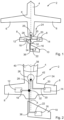
Fig. 1 shows an aircraft having a control system in a schematic plan view. -
Fig. 2 shows a detail of the aircraft and the control system. -
Fig. 1 shows anaircraft 2 having afuselage 4, twowing halves 6,horizontal tail planes 8 and avertical tail plane 10. The latter is shown schematically and it should be clear that thevertical tail plane 10 is arranged perpendicular to thehorizontal tail plane 8. Theaircraft 2 comprises a longitudinal axis x, which also defines a symmetry line for thewing halves 6, thehorizontal tail planes 8 and thevertical tail pane 10. -
Horizontal tail planes 8 comprise afirst control surface 12 in the form of a left-hand elevator and asecond control surface 14 in the form of a right hand elevator. Thevertical tail plane 10 comprises athird control surface 16 in the form of a rudder. Exemplarily, theelevators rudder 16 are coupled with afirst actuator 18, asecond actuator 20 and athird actuator 22, respectively. - The
aircraft 2 comprises acontrol system 24, to which theactuators 18 to 22 belong. Thecontrol system 24 furthermore comprises ahydraulic pump 26, a firsthydraulic line 28 and a secondhydraulic line 30. The first and the secondhydraulic lines hydraulic pump 26, but at different ports. The firsthydraulic line 28 comprises ajunction point 32, to which afirst branch line 34 is connected, leading to thefirst actuator 18. Asecond branch line 36 leads to thethird actuator 22. The secondhydraulic line 30 is connected to thesecond actuator 20. - Hence, the
control system 24 comprises an asymmetric setup, as the firsthydraulic line 28 supplies both the firsthydraulic actuator 18 and the thirdhydraulic actuator 22 with hydraulics fluid. - In
Fig. 2 an enlarged view shows thecontrol system 24 in more detail. Here, the firsthydraulic line 28 comprises the largest diameter, while thefirst branch line 34 and the secondhydraulic line 30 comprise the smallest diameter. The diameter of thesecond branch line 36 has an intermediate diameter that exceeds the diameter of thefirst branch line 34 and the secondhydraulic line 30 and is smaller than the diameter of the firsthydraulic line 28. Thus, the different flow demands in terms of pipe dimensions are respected. - As apparent from
Fig. 2 , apressure bulkhead 38 is arranged in thefuselage 4 and separates apressurized cabin region 40 from anunpressurized fuselage region 42. Thecontrol system 24 is arranged behind thepressure bulkhead 38, such that it is arranged in theunpressurized fuselage region 42. A segregation of hydraulic lines is not required and lines can be routed closer together. Other layouts of mechanical installation become possible, where e.g. hydraulic lines are routed close to the structure and thus provide enough space for APU fuel and bleed lines/other mechanical and electrical systems and other installations. - In addition, it should be noted that "comprising" does not exclude other elements or steps, and "a" or "an" does not exclude a plurality. Further, it should be noted that features that have been described with reference to any of the above embodiments may also be used in combination with other features of other embodiments described above, provided that the combination falls within the scope of the appended claims. Reference signs in the claims are not to be regarded as a limitation.
-
- 2
- aircraft
- 4
- fuselage
- 6
- wing half
- 8
- horizontal tail plane
- 10
- vertical tail plane
- 12
- first control surface / left hand elevator
- 14
- second control surface / right hand elevator
- 16
- third control surface / rudder
- 18
- first actuator
- 20
- second actuator
- 22
- third actuator
- 24
- control system
- 26
- hydraulic pump
- 28
- first hydraulic line
- 30
- second hydraulic line
- 32
- junction point
- 34
- first branch line
- 36
- second branch line
- 38
- pressure bulkhead
- x
- longitudinal axis / symmetry axis
Claims (11)
- An aircraft (2) comprising:- at least one control system (24) for the aircraft, and- a first control surface (12), a second control surface (14) and a third control surface (16);the control system (24) comprising:- a hydraulic pump (26),- a first hydraulic line (28),- a second hydraulic line (30),- at least one first actuator (18) coupled with the first control surface (12),- at least one second actuator (20) coupled with the second control surface (14),- at least one third actuator (22) coupled with the third control surface (16),wherein the aircraft comprises a longitudinal axis as symmetry axis (x) in plan view;wherein the first control surface (12) and the second control surface (14) are arranged at a distance to each other and symmetrically relative to the symmetry axis (x),wherein the third control surface (16) is arranged substantially aligned with the symmetry axis (x),wherein the first hydraulic line (28) and the second hydraulic line (30) are connected to different ports of the hydraulic pump (26),wherein the at least one first actuator (18) is connected to the first hydraulic line (28) at a junction point (32), at which the at least one first actuator is supplied with hydraulic fluid,wherein the at least one second actuator (20) is connected to the second hydraulic line (30),wherein the at least one third actuator (22) is connected to the first hydraulic line (28) downstream of the junction point (32) of the at least one first actuator (18), andwherein the first hydraulic line (28) at least partially comprises a larger diameter than the second hydraulic line (30);wherein the at least one first actuator (18) is connected to the junction port (32) through a first branch line (34), wherein the first hydraulic line (28) comprises a larger diameter than the first branch line (34); andwherein the at least one third actuator (22) is connected to the first hydraulic line (28) through a second branch line (36), wherein the diameter of the first hydraulic line (28) exceeds a diameter of the second branch line (36).
- Aircraft (2) according to claim 1,
wherein a first hydraulic path length from the hydraulic pump (26) to the at least one first actuator (18) differs from a second hydraulic path length from the hydraulic pump (26) to the at least one second actuator (20) by 20% as a maximum. - Aircraft (2) according to claim 2,
wherein a third hydraulic path length from the junction point (32) to the at least one third actuator (22) differs from the first path length and the second path length by 20% as a maximum. - Aircraft (2) according to claim 1,
wherein the diameter of the second branch line (36) exceeds the diameter of the first branch line (34). - Aircraft (2) according to claim 1 or 4,
wherein the diameter of the first branch line (34) and of the second hydraulic line (30) are substantially equal. - Aircraft (2) according to claim 1,
wherein the first branch line (34) is arranged substantially transverse to the first hydraulic line (28). - Aircraft (2) according to claim 1,
wherein the first branch line (34) and the second hydraulic line (30) are arranged in a substantially mirror inverted manner. - Aircraft (2) according to claim 1,
wherein the at least one control system (24) is arranged behind a pressure bulkhead (38) of the aircraft. - Aircraft (2) according to claim 1 or 8,
wherein the first control surface (12) and the second control surface (14) are elevators. - Aircraft (2) according to claim 9,wherein the first control surface (12) is a left hand elevator, andwherein the second control surface (14) is a right hand elevator.
- Aircraft (2) according to any of the claims 1 to 10, wherein the third control surface (16) is a rudder.
Priority Applications (2)
| Application Number | Priority Date | Filing Date | Title |
|---|---|---|---|
| EP21171623.8A EP4082898B1 (en) | 2021-04-30 | 2021-04-30 | Control system for an aircraft |
| US17/731,735 US11731756B2 (en) | 2021-04-30 | 2022-04-28 | Control system for an aircraft |
Applications Claiming Priority (1)
| Application Number | Priority Date | Filing Date | Title |
|---|---|---|---|
| EP21171623.8A EP4082898B1 (en) | 2021-04-30 | 2021-04-30 | Control system for an aircraft |
Publications (2)
| Publication Number | Publication Date |
|---|---|
| EP4082898A1 EP4082898A1 (en) | 2022-11-02 |
| EP4082898B1 true EP4082898B1 (en) | 2024-07-17 |
Family
ID=75746516
Family Applications (1)
| Application Number | Title | Priority Date | Filing Date |
|---|---|---|---|
| EP21171623.8A Active EP4082898B1 (en) | 2021-04-30 | 2021-04-30 | Control system for an aircraft |
Country Status (2)
| Country | Link |
|---|---|
| US (1) | US11731756B2 (en) |
| EP (1) | EP4082898B1 (en) |
Families Citing this family (1)
| Publication number | Priority date | Publication date | Assignee | Title |
|---|---|---|---|---|
| EP4219317A1 (en) * | 2022-02-01 | 2023-08-02 | Eaton Intelligent Power Limited | Fluid module |
Family Cites Families (6)
| Publication number | Priority date | Publication date | Assignee | Title |
|---|---|---|---|---|
| US4428196A (en) * | 1980-10-14 | 1984-01-31 | Mcdonnell Douglas Corporation | Aircraft split hydraulic system |
| JP2011247334A (en) * | 2010-05-26 | 2011-12-08 | Nabtesco Corp | Hydraulic system for aircraft actuator |
| JP5658117B2 (en) * | 2010-11-29 | 2015-01-21 | ナブテスコ株式会社 | Aircraft actuator hydraulic system |
| JP6178587B2 (en) * | 2013-02-28 | 2017-08-09 | 三菱航空機株式会社 | Aircraft actuator device and aircraft |
| JP7101452B2 (en) * | 2016-07-19 | 2022-07-15 | ナブテスコ株式会社 | Electric actuator drive control device and aircraft |
| CN109850133A (en) * | 2019-02-25 | 2019-06-07 | 中国航空工业集团公司西安飞机设计研究所 | A kind of plane hydraulic system |
-
2021
- 2021-04-30 EP EP21171623.8A patent/EP4082898B1/en active Active
-
2022
- 2022-04-28 US US17/731,735 patent/US11731756B2/en active Active
Also Published As
| Publication number | Publication date |
|---|---|
| US11731756B2 (en) | 2023-08-22 |
| EP4082898A1 (en) | 2022-11-02 |
| US20220348313A1 (en) | 2022-11-03 |
Similar Documents
| Publication | Publication Date | Title |
|---|---|---|
| EP2263012B1 (en) | Hydraulic actuator with floating pistons | |
| US5074495A (en) | Load-adaptive hybrid actuator system and method for actuating control surfaces | |
| US5181380A (en) | Hydrostatic operating mode hydraulic actuator preferably for backup operation, and flight control system comprising it | |
| US8505848B2 (en) | Aircraft actuator hydraulic system | |
| US6796526B2 (en) | Augmenting flight control surface actuation system and method | |
| US10787245B2 (en) | Distributed compressor for improved integration and performance of an active fluid flow control system | |
| EP2631171B1 (en) | Aircraft actuator hydraulic system | |
| US20100170999A1 (en) | More electric flight control system onboard an aircraft | |
| EP3378763B1 (en) | Aircraft hydraulic systems having shared components | |
| WO2009124027A1 (en) | Hydraulic system for aircraft | |
| US8596575B2 (en) | Aircraft actuator | |
| Jani et al. | An overview on aircraft hydraulic system | |
| US11731756B2 (en) | Control system for an aircraft | |
| US20140004986A1 (en) | Electric motor/generator power transfer unit | |
| KR20230130995A (en) | Dual tandem electro-actuator | |
| US8677885B2 (en) | Floating piston actuator for operation with multiple hydraulic systems | |
| CN115978040B (en) | Hydraulic control system and overhead working machine | |
| CN110848198A (en) | Zero-oil-leakage energy conversion valve of double hydraulic system | |
| CN113007162B (en) | Aircraft hydraulic system and aircraft | |
| US6718762B2 (en) | Contingency hydraulic power unit | |
| Robinson et al. | Evolution of the MD-95 hydraulic system | |
| JP3281882B2 (en) | Accumulator hydraulic circuit for aircraft variable pressure hydraulic system. |
Legal Events
| Date | Code | Title | Description |
|---|---|---|---|
| PUAI | Public reference made under article 153(3) epc to a published international application that has entered the european phase |
Free format text: ORIGINAL CODE: 0009012 |
|
| STAA | Information on the status of an ep patent application or granted ep patent |
Free format text: STATUS: THE APPLICATION HAS BEEN PUBLISHED |
|
| AK | Designated contracting states |
Kind code of ref document: A1 Designated state(s): AL AT BE BG CH CY CZ DE DK EE ES FI FR GB GR HR HU IE IS IT LI LT LU LV MC MK MT NL NO PL PT RO RS SE SI SK SM TR |
|
| STAA | Information on the status of an ep patent application or granted ep patent |
Free format text: STATUS: REQUEST FOR EXAMINATION WAS MADE |
|
| 17P | Request for examination filed |
Effective date: 20230502 |
|
| RBV | Designated contracting states (corrected) |
Designated state(s): AL AT BE BG CH CY CZ DE DK EE ES FI FR GB GR HR HU IE IS IT LI LT LU LV MC MK MT NL NO PL PT RO RS SE SI SK SM TR |
|
| GRAP | Despatch of communication of intention to grant a patent |
Free format text: ORIGINAL CODE: EPIDOSNIGR1 |
|
| STAA | Information on the status of an ep patent application or granted ep patent |
Free format text: STATUS: GRANT OF PATENT IS INTENDED |
|
| INTG | Intention to grant announced |
Effective date: 20240315 |
|
| GRAS | Grant fee paid |
Free format text: ORIGINAL CODE: EPIDOSNIGR3 |
|
| GRAA | (expected) grant |
Free format text: ORIGINAL CODE: 0009210 |
|
| STAA | Information on the status of an ep patent application or granted ep patent |
Free format text: STATUS: THE PATENT HAS BEEN GRANTED |
|
| AK | Designated contracting states |
Kind code of ref document: B1 Designated state(s): AL AT BE BG CH CY CZ DE DK EE ES FI FR GB GR HR HU IE IS IT LI LT LU LV MC MK MT NL NO PL PT RO RS SE SI SK SM TR |
|
| REG | Reference to a national code |
Ref country code: CH Ref legal event code: EP |
|
| REG | Reference to a national code |
Ref country code: DE Ref legal event code: R096 Ref document number: 602021015685 Country of ref document: DE |
|
| REG | Reference to a national code |
Ref country code: IE Ref legal event code: FG4D |
|
| REG | Reference to a national code |
Ref country code: LT Ref legal event code: MG9D |
|
| REG | Reference to a national code |
Ref country code: NL Ref legal event code: MP Effective date: 20240717 |
|
| PG25 | Lapsed in a contracting state [announced via postgrant information from national office to epo] |
Ref country code: PT Free format text: LAPSE BECAUSE OF FAILURE TO SUBMIT A TRANSLATION OF THE DESCRIPTION OR TO PAY THE FEE WITHIN THE PRESCRIBED TIME-LIMIT Effective date: 20241118 |
|
| REG | Reference to a national code |
Ref country code: AT Ref legal event code: MK05 Ref document number: 1703885 Country of ref document: AT Kind code of ref document: T Effective date: 20240717 |
|
| PG25 | Lapsed in a contracting state [announced via postgrant information from national office to epo] |
Ref country code: NL Free format text: LAPSE BECAUSE OF FAILURE TO SUBMIT A TRANSLATION OF THE DESCRIPTION OR TO PAY THE FEE WITHIN THE PRESCRIBED TIME-LIMIT Effective date: 20240717 |
|
| PG25 | Lapsed in a contracting state [announced via postgrant information from national office to epo] |
Ref country code: PT Free format text: LAPSE BECAUSE OF FAILURE TO SUBMIT A TRANSLATION OF THE DESCRIPTION OR TO PAY THE FEE WITHIN THE PRESCRIBED TIME-LIMIT Effective date: 20241118 Ref country code: NL Free format text: LAPSE BECAUSE OF FAILURE TO SUBMIT A TRANSLATION OF THE DESCRIPTION OR TO PAY THE FEE WITHIN THE PRESCRIBED TIME-LIMIT Effective date: 20240717 |
|
| PG25 | Lapsed in a contracting state [announced via postgrant information from national office to epo] |
Ref country code: NO Free format text: LAPSE BECAUSE OF FAILURE TO SUBMIT A TRANSLATION OF THE DESCRIPTION OR TO PAY THE FEE WITHIN THE PRESCRIBED TIME-LIMIT Effective date: 20241017 |
|
| PG25 | Lapsed in a contracting state [announced via postgrant information from national office to epo] |
Ref country code: FI Free format text: LAPSE BECAUSE OF FAILURE TO SUBMIT A TRANSLATION OF THE DESCRIPTION OR TO PAY THE FEE WITHIN THE PRESCRIBED TIME-LIMIT Effective date: 20240717 Ref country code: PL Free format text: LAPSE BECAUSE OF FAILURE TO SUBMIT A TRANSLATION OF THE DESCRIPTION OR TO PAY THE FEE WITHIN THE PRESCRIBED TIME-LIMIT Effective date: 20240717 Ref country code: GR Free format text: LAPSE BECAUSE OF FAILURE TO SUBMIT A TRANSLATION OF THE DESCRIPTION OR TO PAY THE FEE WITHIN THE PRESCRIBED TIME-LIMIT Effective date: 20241018 |
|
| PG25 | Lapsed in a contracting state [announced via postgrant information from national office to epo] |
Ref country code: BG Free format text: LAPSE BECAUSE OF FAILURE TO SUBMIT A TRANSLATION OF THE DESCRIPTION OR TO PAY THE FEE WITHIN THE PRESCRIBED TIME-LIMIT Effective date: 20240717 |
|
| PG25 | Lapsed in a contracting state [announced via postgrant information from national office to epo] |
Ref country code: LV Free format text: LAPSE BECAUSE OF FAILURE TO SUBMIT A TRANSLATION OF THE DESCRIPTION OR TO PAY THE FEE WITHIN THE PRESCRIBED TIME-LIMIT Effective date: 20240717 |
|
| PG25 | Lapsed in a contracting state [announced via postgrant information from national office to epo] |
Ref country code: IS Free format text: LAPSE BECAUSE OF FAILURE TO SUBMIT A TRANSLATION OF THE DESCRIPTION OR TO PAY THE FEE WITHIN THE PRESCRIBED TIME-LIMIT Effective date: 20241117 Ref country code: AT Free format text: LAPSE BECAUSE OF FAILURE TO SUBMIT A TRANSLATION OF THE DESCRIPTION OR TO PAY THE FEE WITHIN THE PRESCRIBED TIME-LIMIT Effective date: 20240717 |
|
| PG25 | Lapsed in a contracting state [announced via postgrant information from national office to epo] |
Ref country code: HR Free format text: LAPSE BECAUSE OF FAILURE TO SUBMIT A TRANSLATION OF THE DESCRIPTION OR TO PAY THE FEE WITHIN THE PRESCRIBED TIME-LIMIT Effective date: 20240717 |
|
| PG25 | Lapsed in a contracting state [announced via postgrant information from national office to epo] |
Ref country code: ES Free format text: LAPSE BECAUSE OF FAILURE TO SUBMIT A TRANSLATION OF THE DESCRIPTION OR TO PAY THE FEE WITHIN THE PRESCRIBED TIME-LIMIT Effective date: 20240717 Ref country code: RS Free format text: LAPSE BECAUSE OF FAILURE TO SUBMIT A TRANSLATION OF THE DESCRIPTION OR TO PAY THE FEE WITHIN THE PRESCRIBED TIME-LIMIT Effective date: 20241017 |
|
| PG25 | Lapsed in a contracting state [announced via postgrant information from national office to epo] |
Ref country code: RS Free format text: LAPSE BECAUSE OF FAILURE TO SUBMIT A TRANSLATION OF THE DESCRIPTION OR TO PAY THE FEE WITHIN THE PRESCRIBED TIME-LIMIT Effective date: 20241017 Ref country code: PL Free format text: LAPSE BECAUSE OF FAILURE TO SUBMIT A TRANSLATION OF THE DESCRIPTION OR TO PAY THE FEE WITHIN THE PRESCRIBED TIME-LIMIT Effective date: 20240717 Ref country code: NO Free format text: LAPSE BECAUSE OF FAILURE TO SUBMIT A TRANSLATION OF THE DESCRIPTION OR TO PAY THE FEE WITHIN THE PRESCRIBED TIME-LIMIT Effective date: 20241017 Ref country code: LV Free format text: LAPSE BECAUSE OF FAILURE TO SUBMIT A TRANSLATION OF THE DESCRIPTION OR TO PAY THE FEE WITHIN THE PRESCRIBED TIME-LIMIT Effective date: 20240717 Ref country code: IS Free format text: LAPSE BECAUSE OF FAILURE TO SUBMIT A TRANSLATION OF THE DESCRIPTION OR TO PAY THE FEE WITHIN THE PRESCRIBED TIME-LIMIT Effective date: 20241117 Ref country code: HR Free format text: LAPSE BECAUSE OF FAILURE TO SUBMIT A TRANSLATION OF THE DESCRIPTION OR TO PAY THE FEE WITHIN THE PRESCRIBED TIME-LIMIT Effective date: 20240717 Ref country code: GR Free format text: LAPSE BECAUSE OF FAILURE TO SUBMIT A TRANSLATION OF THE DESCRIPTION OR TO PAY THE FEE WITHIN THE PRESCRIBED TIME-LIMIT Effective date: 20241018 Ref country code: FI Free format text: LAPSE BECAUSE OF FAILURE TO SUBMIT A TRANSLATION OF THE DESCRIPTION OR TO PAY THE FEE WITHIN THE PRESCRIBED TIME-LIMIT Effective date: 20240717 Ref country code: ES Free format text: LAPSE BECAUSE OF FAILURE TO SUBMIT A TRANSLATION OF THE DESCRIPTION OR TO PAY THE FEE WITHIN THE PRESCRIBED TIME-LIMIT Effective date: 20240717 Ref country code: BG Free format text: LAPSE BECAUSE OF FAILURE TO SUBMIT A TRANSLATION OF THE DESCRIPTION OR TO PAY THE FEE WITHIN THE PRESCRIBED TIME-LIMIT Effective date: 20240717 Ref country code: AT Free format text: LAPSE BECAUSE OF FAILURE TO SUBMIT A TRANSLATION OF THE DESCRIPTION OR TO PAY THE FEE WITHIN THE PRESCRIBED TIME-LIMIT Effective date: 20240717 |
|
| PG25 | Lapsed in a contracting state [announced via postgrant information from national office to epo] |
Ref country code: DK Free format text: LAPSE BECAUSE OF FAILURE TO SUBMIT A TRANSLATION OF THE DESCRIPTION OR TO PAY THE FEE WITHIN THE PRESCRIBED TIME-LIMIT Effective date: 20240717 Ref country code: SM Free format text: LAPSE BECAUSE OF FAILURE TO SUBMIT A TRANSLATION OF THE DESCRIPTION OR TO PAY THE FEE WITHIN THE PRESCRIBED TIME-LIMIT Effective date: 20240717 Ref country code: RO Free format text: LAPSE BECAUSE OF FAILURE TO SUBMIT A TRANSLATION OF THE DESCRIPTION OR TO PAY THE FEE WITHIN THE PRESCRIBED TIME-LIMIT Effective date: 20240717 |
|
| REG | Reference to a national code |
Ref country code: DE Ref legal event code: R097 Ref document number: 602021015685 Country of ref document: DE |
|
| PG25 | Lapsed in a contracting state [announced via postgrant information from national office to epo] |
Ref country code: EE Free format text: LAPSE BECAUSE OF FAILURE TO SUBMIT A TRANSLATION OF THE DESCRIPTION OR TO PAY THE FEE WITHIN THE PRESCRIBED TIME-LIMIT Effective date: 20240717 |
|
| PG25 | Lapsed in a contracting state [announced via postgrant information from national office to epo] |
Ref country code: CZ Free format text: LAPSE BECAUSE OF FAILURE TO SUBMIT A TRANSLATION OF THE DESCRIPTION OR TO PAY THE FEE WITHIN THE PRESCRIBED TIME-LIMIT Effective date: 20240717 |
|
| PG25 | Lapsed in a contracting state [announced via postgrant information from national office to epo] |
Ref country code: SK Free format text: LAPSE BECAUSE OF FAILURE TO SUBMIT A TRANSLATION OF THE DESCRIPTION OR TO PAY THE FEE WITHIN THE PRESCRIBED TIME-LIMIT Effective date: 20240717 |
|
| PLBE | No opposition filed within time limit |
Free format text: ORIGINAL CODE: 0009261 |
|
| STAA | Information on the status of an ep patent application or granted ep patent |
Free format text: STATUS: NO OPPOSITION FILED WITHIN TIME LIMIT |
|
| 26N | No opposition filed |
Effective date: 20250422 |
|
| PGFP | Annual fee paid to national office [announced via postgrant information from national office to epo] |
Ref country code: DE Payment date: 20250422 Year of fee payment: 5 |
|
| PGFP | Annual fee paid to national office [announced via postgrant information from national office to epo] |
Ref country code: GB Payment date: 20250423 Year of fee payment: 5 |
|
| PGFP | Annual fee paid to national office [announced via postgrant information from national office to epo] |
Ref country code: FR Payment date: 20250425 Year of fee payment: 5 |
|
| PG25 | Lapsed in a contracting state [announced via postgrant information from national office to epo] |
Ref country code: SE Free format text: LAPSE BECAUSE OF FAILURE TO SUBMIT A TRANSLATION OF THE DESCRIPTION OR TO PAY THE FEE WITHIN THE PRESCRIBED TIME-LIMIT Effective date: 20240717 |
|
| REG | Reference to a national code |
Ref country code: CH Ref legal event code: H13 Free format text: ST27 STATUS EVENT CODE: U-0-0-H10-H13 (AS PROVIDED BY THE NATIONAL OFFICE) Effective date: 20251125 |
|
| PG25 | Lapsed in a contracting state [announced via postgrant information from national office to epo] |
Ref country code: LU Free format text: LAPSE BECAUSE OF NON-PAYMENT OF DUE FEES Effective date: 20250430 |
|
| PG25 | Lapsed in a contracting state [announced via postgrant information from national office to epo] |
Ref country code: MC Free format text: LAPSE BECAUSE OF FAILURE TO SUBMIT A TRANSLATION OF THE DESCRIPTION OR TO PAY THE FEE WITHIN THE PRESCRIBED TIME-LIMIT Effective date: 20240717 |
|
| REG | Reference to a national code |
Ref country code: BE Ref legal event code: MM Effective date: 20250430 |
|
| PG25 | Lapsed in a contracting state [announced via postgrant information from national office to epo] |
Ref country code: BE Free format text: LAPSE BECAUSE OF NON-PAYMENT OF DUE FEES Effective date: 20250430 |
|
| PG25 | Lapsed in a contracting state [announced via postgrant information from national office to epo] |
Ref country code: CH Free format text: LAPSE BECAUSE OF NON-PAYMENT OF DUE FEES Effective date: 20250430 |
|
| PG25 | Lapsed in a contracting state [announced via postgrant information from national office to epo] |
Ref country code: IT Free format text: LAPSE BECAUSE OF FAILURE TO SUBMIT A TRANSLATION OF THE DESCRIPTION OR TO PAY THE FEE WITHIN THE PRESCRIBED TIME-LIMIT Effective date: 20240717 |
|
| PG25 | Lapsed in a contracting state [announced via postgrant information from national office to epo] |
Ref country code: IE Free format text: LAPSE BECAUSE OF NON-PAYMENT OF DUE FEES Effective date: 20250430 |