EP4082894A1 - Airfoil system with embedded electric device - Google Patents
Airfoil system with embedded electric device Download PDFInfo
- Publication number
- EP4082894A1 EP4082894A1 EP22170106.3A EP22170106A EP4082894A1 EP 4082894 A1 EP4082894 A1 EP 4082894A1 EP 22170106 A EP22170106 A EP 22170106A EP 4082894 A1 EP4082894 A1 EP 4082894A1
- Authority
- EP
- European Patent Office
- Prior art keywords
- airfoil
- segment
- cavity
- exterior
- exterior surface
- Prior art date
- Legal status (The legal status is an assumption and is not a legal conclusion. Google has not performed a legal analysis and makes no representation as to the accuracy of the status listed.)
- Granted
Links
Images





Classifications
-
- B—PERFORMING OPERATIONS; TRANSPORTING
- B64—AIRCRAFT; AVIATION; COSMONAUTICS
- B64C—AEROPLANES; HELICOPTERS
- B64C3/00—Wings
- B64C3/26—Construction, shape, or attachment of separate skins, e.g. panels
-
- B—PERFORMING OPERATIONS; TRANSPORTING
- B64—AIRCRAFT; AVIATION; COSMONAUTICS
- B64C—AEROPLANES; HELICOPTERS
- B64C3/00—Wings
- B64C3/20—Integral or sandwich constructions
-
- B—PERFORMING OPERATIONS; TRANSPORTING
- B29—WORKING OF PLASTICS; WORKING OF SUBSTANCES IN A PLASTIC STATE IN GENERAL
- B29C—SHAPING OR JOINING OF PLASTICS; SHAPING OF MATERIAL IN A PLASTIC STATE, NOT OTHERWISE PROVIDED FOR; AFTER-TREATMENT OF THE SHAPED PRODUCTS, e.g. REPAIRING
- B29C70/00—Shaping composites, i.e. plastics material comprising reinforcements, fillers or preformed parts, e.g. inserts
- B29C70/68—Shaping composites, i.e. plastics material comprising reinforcements, fillers or preformed parts, e.g. inserts by incorporating or moulding on preformed parts, e.g. inserts or layers, e.g. foam blocks
- B29C70/70—Completely encapsulating inserts
-
- B—PERFORMING OPERATIONS; TRANSPORTING
- B29—WORKING OF PLASTICS; WORKING OF SUBSTANCES IN A PLASTIC STATE IN GENERAL
- B29C—SHAPING OR JOINING OF PLASTICS; SHAPING OF MATERIAL IN A PLASTIC STATE, NOT OTHERWISE PROVIDED FOR; AFTER-TREATMENT OF THE SHAPED PRODUCTS, e.g. REPAIRING
- B29C70/00—Shaping composites, i.e. plastics material comprising reinforcements, fillers or preformed parts, e.g. inserts
- B29C70/88—Shaping composites, i.e. plastics material comprising reinforcements, fillers or preformed parts, e.g. inserts characterised primarily by possessing specific properties, e.g. electrically conductive or locally reinforced
-
- B—PERFORMING OPERATIONS; TRANSPORTING
- B29—WORKING OF PLASTICS; WORKING OF SUBSTANCES IN A PLASTIC STATE IN GENERAL
- B29D—PRODUCING PARTICULAR ARTICLES FROM PLASTICS OR FROM SUBSTANCES IN A PLASTIC STATE
- B29D99/00—Subject matter not provided for in other groups of this subclass
- B29D99/0025—Producing blades or the like, e.g. blades for turbines, propellers, or wings
- B29D99/0028—Producing blades or the like, e.g. blades for turbines, propellers, or wings hollow blades
-
- B—PERFORMING OPERATIONS; TRANSPORTING
- B64—AIRCRAFT; AVIATION; COSMONAUTICS
- B64C—AEROPLANES; HELICOPTERS
- B64C5/00—Stabilising surfaces
- B64C5/06—Fins
-
- B—PERFORMING OPERATIONS; TRANSPORTING
- B64—AIRCRAFT; AVIATION; COSMONAUTICS
- B64D—EQUIPMENT FOR FITTING IN OR TO AIRCRAFT; FLIGHT SUITS; PARACHUTES; ARRANGEMENT OR MOUNTING OF POWER PLANTS OR PROPULSION TRANSMISSIONS IN AIRCRAFT
- B64D43/00—Arrangements or adaptations of instruments
-
- H—ELECTRICITY
- H01—ELECTRIC ELEMENTS
- H01Q—ANTENNAS, i.e. RADIO AERIALS
- H01Q1/00—Details of, or arrangements associated with, antennas
- H01Q1/27—Adaptation for use in or on movable bodies
- H01Q1/28—Adaptation for use in or on aircraft, missiles, satellites, or balloons
- H01Q1/286—Adaptation for use in or on aircraft, missiles, satellites, or balloons substantially flush mounted with the skin of the craft
- H01Q1/287—Adaptation for use in or on aircraft, missiles, satellites, or balloons substantially flush mounted with the skin of the craft integrated in a wing or a stabiliser
Definitions
- This disclosure (invention) relates generally to an aircraft and, more particularly, to systems and devices for arranging one or more electric devices on an exterior of the aircraft.
- a modern aircraft such as an airplane includes a communication system.
- This communication system may include an antenna for relaying signals between the airplane and another remote entity; e.g., another airplane, ground control, satellites, etc.
- This antenna may be mounted on an exterior of the airplane or within an interior of the airplane; e.g., beneath a skin of an airplane fuselage or an airplane wing. While mounting the antenna on the exterior of the airplane may provide a substantially unobstructed signal path between the exposed antenna and the remote entity, exposure of the antenna increases airplane drag. While mounting the antenna within the interior of the airplane reduces airplane drag, a structure (e.g., skin, frame, etc.) surrounding the antenna may interfere with the signal path between the enclosed antenna and the remote entity.
- a structure e.g., skin, frame, etc.
- an aerodynamic fin e.g., an aerodynamic antenna housing.
- This fin is mounted on the exterior of the airplane and, thus, positions the antenna outside of the airplane skin and the internal frame.
- a fin may still interfere with signal transmission between the antenna and the remote entity, particularly where the fin is made from metallic materials and/or uses traditional metal fasteners; e.g., bolts, screws, rivets, etc.
- Known fins may also be difficult and costly to manufacture.
- an airfoil system includes an airfoil and an electric device.
- the airfoil includes a first exterior surface, a second exterior surface, a first airfoil segment and a second airfoil segment attached to the first airfoil segment.
- the airfoil extends widthwise between the first exterior surface and the second exterior surface.
- the first airfoil segment forms the first exterior surface.
- the second airfoil segment forms the second exterior surface.
- the electric device is embedded within the airfoil between the first airfoil segment and the second airfoil segment.
- another airfoil system includes an airfoil body and an electric device.
- the airfoil body includes a first airfoil segment and a second airfoil segment attached to the first airfoil segment.
- the first airfoil segment is configured from or otherwise includes first composite material.
- the first airfoil segment forms a first half of the airfoil body.
- the second airfoil segment is configured from or otherwise includes second composite material.
- the second airfoil segment forms a second half of the airfoil body.
- the electric device is located within an internal cavity of the airfoil body between the first airfoil segment and the second airfoil segment.
- a manufacturing method is provided. During this method, a first airfoil segment is formed as a first monolithic body. A second airfoil segment is formed as a second monolithic body. An electric device is attached to the first airfoil segment. The second airfoil segment is attached to the first airfoil segment to provide an airfoil body. The electric device is embedded within the airfoil body between the first airfoil segment and the second airfoil segment.
- the first airfoil segment and the second airfoil segment may each be configured from or otherwise include non-metallic material.
- the method may also include attaching a shield to the airfoil body to form a leading edge of an airfoil.
- the airfoil may include the airfoil body and the shield.
- the first composite material and/or the second composite material may each be or otherwise include fiberglass reinforcement within a resin matrix.
- the airfoil system may also include an airfoil which includes a first exterior surface, a second exterior surface and the airfoil body.
- the airfoil may extend widthwise between the first exterior surface and the second exterior surface.
- the first airfoil segment may form the first exterior surface.
- the second airfoil segment may form the second exterior surface.
- the electric device may be configured as or otherwise include an antenna.
- the electric device may be configured as or otherwise include a sensor.
- the airfoil may also include an internal cavity formed collectively by the first airfoil segment and the second airfoil segment.
- the electric device may be located at least partially or completely within the internal cavity.
- the internal cavity may extend widthwise within the airfoil between a first cavity side and a second cavity side.
- the first airfoil segment may form the first cavity side.
- the second airfoil segment may form the second cavity side.
- the internal cavity may extend lengthwise within the airfoil between a cavity leading end and a cavity trailing end.
- the first airfoil segment may form a first portion of the cavity leading end and a first portion of the cavity trailing end.
- the second airfoil segment may form a second portion of the cavity leading end and a second portion of the cavity trailing end.
- the internal cavity may extend spanwise within the airfoil between a cavity base end and a cavity tip end.
- the first airfoil segment may form a first portion of the cavity base end and a first portion of the cavity tip end.
- the second airfoil segment may form a second portion of the cavity base end and a second portion of the cavity tip end.
- the electric device may be attached to the first airfoil segment and/or the second airfoil segment.
- the first airfoil segment may be configured as or otherwise include a first exterior skin that forms the first exterior surface.
- the second airfoil segment may be configured as or otherwise include a second exterior skin that forms the second exterior surface.
- the first exterior skin and/or the second exterior skin each be configured from or otherwise include composite material.
- the first airfoil segment may include a first exterior skin and a first internal support formed integral with the first exterior skin.
- the first exterior skin may form the first exterior surface.
- the second airfoil segment may include a second exterior skin and a second internal support formed integral with the second exterior skin.
- the second exterior skin may form the second exterior surface.
- the first internal support may engage and may be attached to the second internal support.
- the first internal support may be abutted against and bonded to the second internal support.
- the first internal support may include a receptacle.
- the second internal support may include a key that is mated with the receptacle.
- the airfoil may be configured as or otherwise include an airfoil body.
- the first airfoil segment may be a first half of the airfoil body.
- the second airfoil segment may be a second half of the airfoil body.
- the airfoil may also include a shield.
- the shield may be configured at and extend spanwise along a leading edge of the airfoil.
- the shield may overlap and may be attached to a first leading edge portion of the first airfoil segment and a second leading edge portion of the second airfoil segment.
- the present disclosure may include any one or more of the individual features disclosed above and/or below alone or in any combination thereof.
- FIG. 1 illustrates a portion of an assembly 20 for an aircraft.
- the term "aircraft” may generally describe any mobile device which travels through at least air and/or space.
- the aircraft for example, may be configured as an airplane, a helicopter, a spacecraft, a drone (e.g., an unmanned aerial vehicle (UAV)) or a projectile such as, but not limited to, a rocket.
- UAV unmanned aerial vehicle
- the present disclosure is not limited to the foregoing exemplary aircraft configurations.
- the aircraft assembly 20 of FIG. 1 includes a base 22 and an airfoil system 24.
- the aircraft assembly base 22 may be any portion of the aircraft to which the airfoil system 24 may be mounted.
- the aircraft assembly base 22, for example, may be configured as an exterior skin or other exterior structure of: an aircraft fuselage, an aircraft tail assembly, an aircraft wing, an engine pylon or a nacelle housing an aircraft engine.
- the present disclosure is not limited to the foregoing exemplary aircraft assembly base configurations.
- the airfoil system 24 of FIG. 1 is configured to at least partially or completely form an aerodynamic projection (e.g., a control element, a control surface, etc.) on the aircraft assembly base 22.
- the airfoil system 24 of FIG. 1 includes a hollow airfoil 26.
- This airfoil 26 may be configured as a wing, a vane, a fin and/or a vortex generator (e.g., a strake).
- the wing may include, but are not limited to, a winglet, a stub wing, a main wing, a tail wing and a stabilizer.
- the airfoil system 24 of FIG. 1 is also configured as part of an electronic system 28 of the aircraft such as, but not limited to, a communication system and/or a sensor system.
- the airfoil system 24 of FIG. 1 includes at least one electric device 30 configured with (e.g., housed within) the airfoil 26.
- This electric device 30 may be configured as or otherwise include an antenna such as, but not limited to, a VHF antenna.
- the electric device 30 may also or alternatively be configured as or otherwise include a sensor such as, but not limited to, a prognostics and health management (PHM) sensor.
- PLM prognostics and health management
- the airfoil 26 is constructed substantially (or only) from non-metallic and/or dielectric material(s). More particularly, at least a significant portion of a hollow body 32 of the airfoil 26 that forms a housing and/or a shell about the electric device 30 may be constructed substantially (or only) from the non-metallic and/or dielectric material(s).
- the airfoil 26 may be configured with a segmented (e.g., clamshell-like) construction.
- the airfoil 26 may be configured without, for example, any traditional fasteners (e.g., bolts, screws, rivets, etc.) for securing its airfoil segments 34A and 34B (generally referred to as "34") together. Additional details regarding the construction of the airfoil 26 are described below in further detail.
- the airfoil system 24 of FIG. 1 includes the airfoil 26 and an airfoil mount 36 configured to attach / secure the airfoil system 24 and its airfoil 26 to the aircraft assembly base 22.
- the airfoil system 24 of FIG. 1 also includes the electric device 30 configured (e.g., embedded, encapsulated and/or otherwise disposed) within the airfoil 26.
- the airfoil system 24 may be configured without the electric device 30 in order to provide the aerodynamic projection described herein without also being part of the aircraft electronic system 28.
- the airfoil 26, for example, may be configured to form a hollow aircraft control element without housing any electric devices therewithin.
- the airfoil 26 of FIG. 1 is configured with / includes its hollow airfoil body 32.
- the airfoil 26 of FIG. 1 also includes a leading edge (LE) shield 38 configured to protect the airfoil body 32 at a leading edge 40 of the airfoil 26.
- LE leading edge
- the airfoil body 32 extends spanwise along a centerline 42 (e.g., a span line) of the airfoil 26 from a base 44 (e.g., a root) of the airfoil 26 to a tip 46 of the airfoil 26.
- the airfoil body 32 extends lengthwise along a camber line 48 of the airfoil 26 from a leading edge 50 of the airfoil body 32 to a trailing edge 52 of the airfoil 26, where the airfoil body leading edge 50 is arranged at (e.g., on, adjacent or proximate) the airfoil leading edge 40.
- a centerline 42 e.g., a span line
- the airfoil body 32 extends lengthwise along a camber line 48 of the airfoil 26 from a leading edge 50 of the airfoil body 32 to a trailing edge 52 of the airfoil 26, where the airfoil body leading edge 50 is arranged at (e.g.
- the airfoil body leading edge 50 is slightly recessed inward from the airfoil leading edge 40 by a thickness of the shield 38.
- the airfoil body leading edge 50 may be on (e.g., the same as) the airfoil leading edge 40 where, for example, the shield 38 is omitted or incorporated as part of the airfoil body 32.
- the airfoil body 32 extends widthwise (e.g., transverse to the centerline 42 and/or the camber line 48) between and to opposing side exterior surfaces 54A and 54B (generally referred to as "54") of the airfoil body 32; e.g., exterior-most / outer-most surfaces of the airfoil body 32.
- Each of these airfoil body exterior surfaces 54 may be configured as a convex surface as shown in FIG. 3 .
- either one of the airfoil body exterior surfaces 54A or 54B may be a concave surface (see FIG. 4A ) or a substantially flat surface (see FIG. 4B ).
- the airfoil body 32 includes the plurality of airfoil segments 34; e.g., a complimentary pair of airfoil segments. These airfoil segments 34 may be configured as respective halves of the airfoil body 32.
- the airfoil segment 34A may form one half (or portion) of the airfoil body 32 on one side of the airfoil body 32; e.g., towards the airfoil body exterior surface 54A.
- the airfoil segment 34B may form the other remaining half (or portion) of the airfoil body 32 on an opposing side of the airfoil body 32; e.g., towards the airfoil body exterior surface 54B.
- the airfoil segments 34 of FIG. 3 have substantially identical (but, mirror image) configurations.
- the present disclosure is not limited to such an exemplary identical, mirror image configuration.
- the airfoil segments 34 may alternatively have different (but, still complementary) configurations.
- each airfoil segment 34 extends spanwise along the centerline 42 from (or about) the airfoil base 44 to the airfoil tip 46.
- Each airfoil segment 34 extends lengthwise along the camber line 48 from the airfoil body leading edge 50 (or, alternatively the airfoil leading edge 40) to the airfoil trailing edge 52.
- Each airfoil segment 34 extends widthwise from an interior side 56 (e.g., an intersegment mating side) of the respective airfoil segment 34 to the airfoil body exterior surface 54 that is formed by that respective airfoil segment 34.
- each airfoil segment 34 includes an exterior skin 58 and one or more (e.g., discrete or interconnected) internal supports 60-62.
- One or each of the airfoil segments 34 may also include an electric device mount 64.
- the exterior skin 58 is configured to at least partially or completely form an exterior periphery of the respective airfoil segment 34.
- the exterior skin 58 of FIG. 5 (e.g., completely) forms its respective airfoil body exterior surface 54.
- the exterior skin 58 of FIG. 5 also (e.g., partially) forms the airfoil body leading edge 50, the airfoil trailing edge 52 and/or the airfoil tip 46. More particularly, the exterior skin 58 of FIG. 5 extends spanwise from (or about) the airfoil base 44 to (or about) the airfoil tip 46, and lengthwise from (or about) the airfoil body leading edge 50 to (or about) the airfoil trailing edge 52.
- a leading edge end of the exterior skin 58 may thereby at least partially form the airfoil body leading edge 50.
- a trailing edge end of the exterior skin 58 may at least partially for the airfoil trailing edge 52.
- the exterior skin 58 of FIG. 5 also extends widthwise across the airfoil tip 46 to the airfoil segment interior side 56, and lengthwise across the airfoil tip 46 between and to the edges 50 and 52. The exterior skin 58 may thereby form a portion of the airfoil tip 46 that is carried by the respective airfoil segment 34.
- each of the internal supports 60-62 may be configured as an internal stiffener (e.g., a structural rib or other member) for supporting and providing rigidity to the respective exterior skin 58.
- Each of the internal supports 60-62 for example, is arranged on the airfoil segment interior side 56 and is connected to (e.g., formed integral with) the respective exterior skin 58.
- the leading edge (LE) support 60 is arranged at (e.g., on, adjacent or proximate) the airfoil body leading edge 50.
- This LE support 60 extends spanwise between and to (or about) the airfoil base 44 and the airfoil tip 46.
- the trailing edge (TE) support 61 is arranged at (e.g., on, adjacent or proximate) the airfoil trailing edge 52.
- This TE support 61 extends spanwise between and to (or about) the airfoil base 44 and the airfoil tip 46.
- the intermediate support 62 is arranged intermediately (e.g., about midway) spanwise along the centerline 42 between the airfoil base 44 and the airfoil tip 46. This intermediate support 62 extends lengthwise between and to (or about) the LE support 60 and the TE support 61.
- each of the internal supports 60-62 may have a channeled and/or tubular configuration; e.g., a hat or top-hat configuration.
- Each internal support 60, 61, 62 may be configured as a flanged (e.g., outward lipped, or inward lipped) U-channel, C-channel or V-channel beam.
- each internal support 60, 61, 62 may have a flanged U-shaped, C-shaped or V-shaped cross-sectional geometry when viewed, for example, in a plane perpendicular to a longitudinal centerline of the internal support; e.g., the plane of FIG. 8 .
- the present disclosure is not limited to the foregoing exemplary internal support configurations.
- Each internal support 60, 61, 62 may include one or more internal sidewalls 66 and 68 (e.g., structural flanges) and an internal endwall 70 (e.g., a structural web). These support elements 66, 68 and 70 are configured together to collectively provide the respective internal support 60, 61, 62 with an internal support channel 72.
- This channel 72 extends longitudinally along the longitudinal centerline of the respective internal support, where the channel 72 of FIG. 8 is closed off by an interior peripheral portion of the exterior skin 58 of the respective airfoil segment 34.
- Each internal support 60, 61, 62 may also include one or more outward lips 74 and 76 (or inward lips) for fixing the internal support 60, 61, 62 to the exterior skin 58.
- the internal support members 66, 68, 70, 74 and 76 of FIG. 8 are integrally connected together, and each internal support 60, 61, 62 is integrally connected to the respective exterior skin 58 as described below in further detail.
- Each of the internal support members 66, 68, 70, 74 and 76 may extend longitudinally along a portion or an entire longitudinal length of the respective internal support 60, 61, 62.
- the first sidewall 66 is connected to the respective exterior skin 58 at an interior of the respective airfoil segment 34 via, for example, the first lip 74.
- the first lip 74 is connected to and projects out (e.g., in a first direction away from the channel 72) from the first sidewall 66.
- the first lip 74 of FIG. 8 extends along and is connected to the respective exterior skin 58.
- the first sidewall 66 projects inward from the respective exterior skin 58 and the first lip 74 to a distal end 78 of the respective internal support 60, 61, 62.
- the second sidewall 68 is connected to the respective exterior skin 58 at the interior of the respective airfoil segment 34 via, for example, the second lip 76.
- the second lip 76 is connected to and projects out (e.g., in a second direction away from the channel 72 that is opposite the first direction) from the second sidewall 68.
- the second lip 76 of FIG. 8 extends along and is connected to the respective exterior skin 58.
- the second sidewall 68 projects inward from the respective exterior skin 58 and the second lip 76 to the distal end 78 of the respective internal support 60, 61, 62.
- the endwall 70 is arranged at (e.g., on, adjacent or proximate) the distal end 78 of the respective internal support 60, 61, 62.
- the endwall 70 of FIG. 8 is connected to and extends between the first sidewall 66 and the second sidewall 68.
- the internal support channel 72 extends between and to the respective exterior skin 58 and the endwall 70.
- the internal support channel 72 also extends between and to the opposing sidewalls 66 and 68.
- Each internal support 60, 61, 62 may also include a segment-to-segment mount 80 (e.g., an inter-lockable coupler, an interface, etc.), which is shown schematically in FIGS. 6-9 .
- each segment mount 80 may extend longitudinally along the respective internal support 60, 61, 62.
- a longitudinal length 82 of the segment mount 80 may be equal to or less than a longitudinal length 84 of the respective internal support 60, 61, 62.
- the segment mount length 82 may be greater than fifty percent (50%), sixty percent (60%), seventy percent (70%), eighty percent (80%) or ninety percent (90%) of the internal support length 84, but equal to or less than the internal support length 84.
- the segment mount 80 may extend uninterrupted along its entire longitudinal length 82. In other embodiments, the segment mount 80 may be longitudinally interrupted; e.g., cut, formed by multiple spaced (or abutted) segments represented by dashed lines 86 in FIG. 9 , etc.
- the segment mount 80 is connected to (e.g., formed integral with) the respective endwall 70.
- a base 88 of the segment mount 80 may be embedded within (or otherwise configured with and/or coupled to) material of the respective endwall 70.
- a first portion 90 of the endwall material in FIG. 8 overlaps a first side 92 of the segment mount base 88.
- the base first side 92 is thereby captured (e.g., sandwiched) between and secured (e.g., bonded) to the first portion 90 of the endwall material and a base portion 94 of the endwall material.
- a second portion 96 of the endwall material in FIG. 8 overlaps a second side 98 of the segment mount base 88.
- the base second side 98 is thereby captured (e.g., sandwiched) between and secured (e.g., bonded) to the second portion 96 of the endwall material and the base portion 94 of the endwall material.
- An interface 100 of the segment mount 80 is connected to (e.g., formed integral with) and projects out from the segment mount base 88 to a distal end of the segment mount interface 100 / the segment mount 80.
- This segment mount interface 100 is configured to mate with another one of the segment mount interfaces 100 configured with the corresponding internal support 60, 61, 62 of the other (e.g., opposing) airfoil segment 34.
- one of the segment mounts 80 may be configured as a receptacle 102 with a receptacle aperture 104; e.g., a channel, a slot, a groove, etc.
- the other one of the segment mounts 80 may be configured as a key 106 with a key protrusion 108; e.g., a rib, a rail, a rim, etc.
- a key protrusion 108 may project into the receptacle aperture 104 to provide an inter-locking (e.g., tongue-and-groove) interface between the respective segment mounts 80.
- the key 106 and its protrusion 108 may also be attached (e.g., bonded) to the receptacle 102 to fixedly secure the engaged (e.g., interlocked) segment mounts 80 together.
- the electric device mount 64 is arranged at the interior of the respective airfoil segment 34.
- the electric device mount 64 of FIGS. 6 and 7 for example, is arranged lengthwise between the LE support 60 and the TE support 61.
- This electric device mount 64 is also arranged spanwise between the intermediate support 62 and the airfoil tip 46.
- the electric device mount 64 may be spaced from the respective exterior skin 58 by a (e.g., air) gap 110.
- the electric device mount 64 may be connected to (e.g., formed integral with) one or more or each of the internal supports 60-62 of the respective airfoil segment 34.
- the electric device mount 64 may extend lengthwise between and to the LE support 60 and the TE support 61. As best seen in FIG. 6 , the electric device mount 64 may also or alternatively project out from the intermediate support 62 towards the airfoil tip 46.
- the electric device mount 64 may be configured as an internal mounting tray.
- the electric device mount 64 of FIGS. 6 and 7 for example, has a generally plate-like configuration.
- the airfoil body 32 is formed by attaching the airfoil segments 34 together.
- the edges of the exterior skins 58 are aligned, for example, and may be attached (e.g., bonded) together using bonding material such as resin or any other adhesive, and/or joined via a sealant material.
- Internal support structures (e.g., networks of the internal supports 60-62) of the airfoil segments 34 are also aligned and may be attached (e.g., bonded) together using bonding material such as resin or any other adhesive.
- the LE support 60 of one of the airfoil segments 34A is aligned with the LE support 60 of the other one of the airfoil segments 34B.
- the segment mounts 80 of those LE supports 60 are mated and/or secured together as described above; e.g., see FIG. 10 .
- the TE support 61 of one of the airfoil segments 34A is aligned with the TE support 61 of the other one of the airfoil segments 34B.
- the segment mounts 80 of those TE supports 61 are mated and/or secured together as described above; e.g., see FIG. 10 .
- the intermediate support 62 of one of the airfoil segments 34A is aligned with the intermediate support 62 of the other one of the airfoil segments 34B.
- the segment mounts 80 of those intermediate supports 62 are mated and/or secured together as described above; e.g., see FIG. 10 .
- the airfoil segments 34 may be connected together without, for example, use of any traditional (e.g., metal and/or otherwise) fasteners; e.g., bolts, screws, rivets, etc.
- the airfoil body 32 may therefore be a fastener-free body.
- the airfoil body 32 is configured with one or more internal cavities 112-115.
- the leading edge (LE) cavity 112 is arranged at the airfoil body leading edge 50.
- This LE cavity 112 is formed collectively by the joined exterior skins 58 and the joined LE supports 60.
- the LE cavity 112 for example, extends lengthwise within the airfoil body 32 from the joined exterior skins 58 to the joined LE supports 60.
- the LE cavity 112 extends widthwise within the airfoil body 32 between the opposing exterior skins 58.
- the LE cavity 112 extends spanwise within the airfoil body 32, and along the airfoil body leading edge 50, from (or about) the airfoil base 44 to the joined exterior skins 58 at the airfoil tip 46; see also FIG. 6 .
- the trailing edge (TE) cavity 113 is arranged at the airfoil trailing edge 52.
- This TE cavity 113 is formed collectively by the joined exterior skins 58 and the joined TE supports 61.
- the TE cavity 113 for example, extends lengthwise within the airfoil body 32 from the joined exterior skins 58 to the joined TE supports 61.
- the TE cavity 113 extends widthwise within the airfoil body 32 between the opposing exterior skins 58.
- the TE cavity 113 extends spanwise within the airfoil body 32, and along the airfoil trailing edge 52, from (or about) the airfoil base 44 to the joined exterior skins 58 at the airfoil tip 46; see also FIG. 6 .
- the inner cavity 114 is arranged at the airfoil base 44.
- This inner cavity 114 is formed collectively by the joined exterior skins 58, the joined LE supports 60, the joined TE supports 61 and the joined intermediate supports 62.
- the inner cavity 114 extends lengthwise within the airfoil body 32 from the joined LE supports 60 to the joined TE supports 61.
- the inner cavity 114 extends widthwise within the airfoil body 32 between the opposing exterior skins 58.
- the inner cavity 114 extends spanwise within the airfoil body 32 from (or about) the airfoil base 44 to the joined intermediate supports 62.
- the outer (e.g., electric device) cavity 115 is arranged at the airfoil tip 46.
- This outer cavity 115 is formed collectively by the joined exterior skins 58, the joined LE supports 60, the joined TE supports 61, the joined intermediate supports 62 and the electric device mounts 64.
- the outer cavity 115 extends lengthwise within the airfoil body 32 from the joined LE supports 60 (e.g., a leading edge (LE) end of the outer cavity 115) to the joined TE supports 61 (e.g., a trailing edge (TE) end of the outer cavity 115).
- the outer cavity 115 extends widthwise within the airfoil body 32 between the opposing exterior skins 58 and/or the opposing electric device mounts 64; e.g., between opposing sides of the outer cavity 115.
- the outer cavity 115 extends spanwise within the airfoil body 32 from the joined intermediate supports 62 (e.g., a lower, base end of the outer cavity 115) to the joined exterior skins 58 at the airfoil tip 46 (e.g., an upper, tip end of the outer cavity 115).
- the outer cavity 115 of FIGS. 11 and 12 is configured (e.g., shaped and sized) to at least partially or completely receive the electric device 30 therewith.
- the electric device 30 may thereby be arranged within the outer cavity 115 (prior to assembly and attachment of the airfoil segments 34).
- the electric device 30 may be secured within the airfoil body 32 by attaching the electric device 30 to one or each of the airfoil segments 34.
- the electric device 30 of FIGS. 11 and 12 may be attached (e.g., bonded) to one or each of the opposing electric device mounts 64 using bonding material such as resin or any other adhesive.
- the shield 38 of FIG. 11 is configured to protect the airfoil body leading edge 50 from foreign object damage (FOD), erosion and/or other damage.
- the shield 38 may be formed from a durable material such as metal; e.g., nickel (Ni).
- the shield 38 is attached to the airfoil body 32.
- a leading edge portion of the airfoil body 32 for example, is inserted into an internal channel of the shield 38 such that an interior surface 118 of the shield 38 is engaged with (e.g., abutted against) an exterior (e.g., the surfaces 54) of the airfoil body 32 at its leading edge 50.
- the shield 38 may be attached (e.g., bonded) to the airfoil body 32 and its exterior skins 58 using bonding material such as resin or any other adhesive.
- the shield 38 may extend along a majority (e.g., at least 80-90%) or an entirety of the airfoil body leading edge 50.
- the shield 38 of FIG. 1 may thereby at least partially or completely form the airfoil leading edge 40.
- the shield 38 also forms leading edge portions of opposing exterior surfaces 120A and 120B (generally referred to as "120") (e.g., exposed side surfaces) of the airfoil 26.
- the remaining portions (and substantially a majority) of the opposing airfoil exterior surfaces 120 are formed by exposed portions of the exterior skins 58 and their exterior surfaces 54.
- the exterior skins 58 of the airfoil body 32 are thereby arranged at and may at least partially form (or completely form where the shield 38 is omitted) the opposing airfoil exterior surfaces 120.
- the airfoil mount 36 is arranged at the airfoil base 44.
- the airfoil mount 36 is connected to (e.g., formed integral with) the airfoil body 32.
- the airfoil mount 36 of FIG. 1 for example, includes one or more flanges 122A and 122B (generally referred to as "122"); see also FIG. 12 . Each of these flanges 122 is connected to and projects outward from a respective one of the exterior skins 58.
- the airfoil mount 36 and its flanges 122 are connected (e.g., mechanically fastened, bonded and/or otherwise attached) to the aircraft assembly base 22 to fixedly secure the airfoil system 24 and its airfoil 26 to the aircraft assembly base 22.
- the airfoil mount 36 may be mechanically fastened to the aircraft assembly base 22 using one or more fasteners 124, and/or bonded using bonding material such as resin or any other adhesive.
- the airfoil body 32 and its airfoil segments 34 may be constructed substantially (or only) from the non-metallic and/or dielectric material(s).
- the airfoil body 32 and its airfoil segments 34 may be constructed substantially (or only) from composite material such as, but not limited to, non-metallic fiber reinforcement within a matrix.
- non-metallic fiber reinforcement is, but is not limited to, fiberglass.
- matrix is, but is not limited to, polymer (e.g., thermoplastic or thermoset) resin.
- each airfoil segment 34 and its various components 58, 60-62 and 64 may be formed together as a single, monolithic body.
- monolithic may described a single, unitary body formed (e.g., resin pressure molded (RPM), resin transfer molded (RTM) or otherwise constructed) as a single collective mass of material.
- RPM resin pressure molded
- RTM resin transfer molded
- segment mounts 80 may be constructed from material that is different than the material (e.g., the non-metallic and/or dielectric material(s)) of the remainder their respective airfoil segment 34, each segment mount 80 may be laid up integrally with and incorporated with the other material during the formation process.
- non-monolithic may also describe herein a single, unitary body formed from discrete elements that are permanently attached together via, for example, fusion, welding and/or an adhesive (e.g., epoxy resin).
- a non-monolithic body includes discretely formed bodies which are removably attached together; e.g., mechanically fastened together, brazed together, etc.
- the segment mounts 80 may be constructed from material that is different than the remainder their respective airfoil segment 34.
- Each segment mount 80 for example, may be constructed from metal such as, but not limited to, aluminum (Al).
- Al aluminum
- the segment mount material may be selected to provide a more robust, rigid, precise connection between the airfoil segments 34.
- one or more of the segment mounts 80 may be constructed from composite material (e.g., non-metallic material), which composite material may be the same or different than the material forming the remainder of the respective airfoil segment 34.
- one or more respective pairs of the segment mounts 80 may be omitted as shown, for example, in FIG. 13 .
- One or more of respective sets of endwalls 70 may be joined directly together via, for example, an adhesive butt connection.
- Each airfoil segment 34 may be formed using resin pressure molding (RPM), resin transfer molding (RTM) and/or various other molding process.
- RPM resin pressure molding
- RTM resin transfer molding
- one or more plies of reinforcement material e.g., fiberglass
- the reinforcement material may be arranged to form a preform (e.g., a body having a general shape) of the respective airfoil segment 34 and each of its members 58, 60-62 and 64.
- the respective segment mounts 80 may also be laid up with the reinforcement material (e.g., between the plies) such that those mounts 80 are formed integral with the airfoil segment 34; e.g., see FIGS. 8 and 10 .
- the mold may then be closed, and resin may be injected into the closed mold under pressure to infiltrate the reinforcement material and form a matrix in which the reinforcements material is embedded.
- the resin may then be cured under elevated pressure and/or an elevated temperature.
- the mandrels are removed from the airfoil segment 34 and the airfoil segment 34 is removed from the mold.
- Each airfoil segment 34 may thereby be integrally formed using a single molding process. This may reduce complexity and/or costs of airfoil manufacture.
- the present disclosure is not limited to the foregoing exemplary manufacturing techniques.
- FIG. 14 is a flow diagram of a method 1400 for manufacturing an airfoil system such as the airfoil system 24 described above.
- each of the airfoil segments 34 is provided.
- Each airfoil segment 34 may be formed as described above using resin pressure molding (RPM), resin transfer molding (RTM) and/or various other molding process.
- the electric device 30 is attached to a first of the airfoil segment (e.g., 34A).
- the electric device 30, for example, may be attached (e.g., bonded) to the electric device mount 64 of the first airfoil segment (e.g., 34A).
- the airfoil body 32 is assembled.
- Bonding material for example, may be applied to one or more mating portions of one or both of the airfoil segments 34.
- the airfoil segments 34 may then be aligned and mated as described above such that the bonding material attaches the airfoil segments 34 together. Additional bonding material may also be applied to further secure the electric device 30 to the second airfoil segment (e.g., 34B) and its electric device mount 64.
- the shield 38 is configured with the airfoil body 32 to provide the airfoil 26.
- the airfoil body 32 for example, may be mated with and attached to the shield 38 as described above.
- the method 1400 may be modified to include one or more additional steps and/or to omit one or more of the foregoing steps.
- the method 1400 may include one or more formation (e.g., machining, cutting, etc.) processes and/or one or more finishing (e.g., sanding, treating, coating, etc.) processes.
- the method 1400 may also or alternatively omit the step 1404 and/or the step 1408 where, for example, the airfoil 26 is configured without the electric device 30 and/or the shield 38.
- the airfoil body 32 and its airfoil segments 34 may be constructed substantially (or only) from the non-metallic and/or dielectric material(s) as described above.
- the internal support structure / airfoil frame e.g., the internal supports 60, 61 and/or 62
- the exterior skins 58 may be constructed from the non-metallic and/or dielectric material, whereas one or more of the internal supports 60, 61 and/or 62 may be constructed from the other material; e.g., metal.
- the internal supports 60, 61 and/or 62 may be formed discretely and then formed integral with the exterior skins 58 in, for example, a similar manner as described above with respect to the segment mounts 80.
- each segment mount 80 may be formed with a respective one of the internal supports 60, 61, 62 as a monolithic (e.g., metal) body or bonded to that internal support after formation.
- the (e.g., metal) internal supports 60, 61 and/or 62 may be bonded to the exterior skins 58 following formation thereof.
- the present disclosure therefore is not limited to any particular materials or construction techniques.
Landscapes
- Engineering & Computer Science (AREA)
- Aviation & Aerospace Engineering (AREA)
- Mechanical Engineering (AREA)
- Chemical & Material Sciences (AREA)
- Composite Materials (AREA)
- Physics & Mathematics (AREA)
- Astronomy & Astrophysics (AREA)
- General Physics & Mathematics (AREA)
- Remote Sensing (AREA)
- Structures Of Non-Positive Displacement Pumps (AREA)
- Manufacturing & Machinery (AREA)
- Transportation (AREA)
Abstract
Description
- This disclosure (invention) relates generally to an aircraft and, more particularly, to systems and devices for arranging one or more electric devices on an exterior of the aircraft.
- A modern aircraft such as an airplane includes a communication system. This communication system may include an antenna for relaying signals between the airplane and another remote entity; e.g., another airplane, ground control, satellites, etc. This antenna may be mounted on an exterior of the airplane or within an interior of the airplane; e.g., beneath a skin of an airplane fuselage or an airplane wing. While mounting the antenna on the exterior of the airplane may provide a substantially unobstructed signal path between the exposed antenna and the remote entity, exposure of the antenna increases airplane drag. While mounting the antenna within the interior of the airplane reduces airplane drag, a structure (e.g., skin, frame, etc.) surrounding the antenna may interfere with the signal path between the enclosed antenna and the remote entity.
- As a compromise between mounting the antenna within the interior of the airplane and having the antenna exposed on the exterior of the airplane, it is known in the art to dispose the antenna within an aerodynamic fin; e.g., an aerodynamic antenna housing. This fin is mounted on the exterior of the airplane and, thus, positions the antenna outside of the airplane skin and the internal frame. However, such a fin may still interfere with signal transmission between the antenna and the remote entity, particularly where the fin is made from metallic materials and/or uses traditional metal fasteners; e.g., bolts, screws, rivets, etc. Known fins may also be difficult and costly to manufacture.
- There is a need in the art for improved techniques and/or assemblies for housing an electric device such as an antenna on an exterior of an aircraft.
- According to an aspect of the present invention, an airfoil system is provided that includes an airfoil and an electric device. The airfoil includes a first exterior surface, a second exterior surface, a first airfoil segment and a second airfoil segment attached to the first airfoil segment. The airfoil extends widthwise between the first exterior surface and the second exterior surface. The first airfoil segment forms the first exterior surface. The second airfoil segment forms the second exterior surface. The electric device is embedded within the airfoil between the first airfoil segment and the second airfoil segment.
- According to another aspect of the present invention, another airfoil system is provided that includes an airfoil body and an electric device. The airfoil body includes a first airfoil segment and a second airfoil segment attached to the first airfoil segment. The first airfoil segment is configured from or otherwise includes first composite material. The first airfoil segment forms a first half of the airfoil body. The second airfoil segment is configured from or otherwise includes second composite material. The second airfoil segment forms a second half of the airfoil body. The electric device is located within an internal cavity of the airfoil body between the first airfoil segment and the second airfoil segment.
- According to another aspect of the present invention, a manufacturing method is provided. During this method, a first airfoil segment is formed as a first monolithic body. A second airfoil segment is formed as a second monolithic body. An electric device is attached to the first airfoil segment. The second airfoil segment is attached to the first airfoil segment to provide an airfoil body. The electric device is embedded within the airfoil body between the first airfoil segment and the second airfoil segment.
- The following optional features may be applied to any of the above aspects.
- The first airfoil segment and the second airfoil segment may each be configured from or otherwise include non-metallic material.
- The method may also include attaching a shield to the airfoil body to form a leading edge of an airfoil. The airfoil may include the airfoil body and the shield.
- The first composite material and/or the second composite material may each be or otherwise include fiberglass reinforcement within a resin matrix.
- The airfoil system may also include an airfoil which includes a first exterior surface, a second exterior surface and the airfoil body. The airfoil may extend widthwise between the first exterior surface and the second exterior surface. The first airfoil segment may form the first exterior surface. The second airfoil segment may form the second exterior surface.
- The electric device may be configured as or otherwise include an antenna.
- The electric device may be configured as or otherwise include a sensor.
- The airfoil may also include an internal cavity formed collectively by the first airfoil segment and the second airfoil segment. The electric device may be located at least partially or completely within the internal cavity.
- The internal cavity may extend widthwise within the airfoil between a first cavity side and a second cavity side. The first airfoil segment may form the first cavity side. The second airfoil segment may form the second cavity side.
- The internal cavity may extend lengthwise within the airfoil between a cavity leading end and a cavity trailing end. The first airfoil segment may form a first portion of the cavity leading end and a first portion of the cavity trailing end. The second airfoil segment may form a second portion of the cavity leading end and a second portion of the cavity trailing end.
- The internal cavity may extend spanwise within the airfoil between a cavity base end and a cavity tip end. The first airfoil segment may form a first portion of the cavity base end and a first portion of the cavity tip end. The second airfoil segment may form a second portion of the cavity base end and a second portion of the cavity tip end.
- The electric device may be attached to the first airfoil segment and/or the second airfoil segment.
- The first airfoil segment may be configured as or otherwise include a first exterior skin that forms the first exterior surface. The second airfoil segment may be configured as or otherwise include a second exterior skin that forms the second exterior surface. The first exterior skin and/or the second exterior skin each be configured from or otherwise include composite material.
- The first airfoil segment may include a first exterior skin and a first internal support formed integral with the first exterior skin. The first exterior skin may form the first exterior surface. The second airfoil segment may include a second exterior skin and a second internal support formed integral with the second exterior skin. The second exterior skin may form the second exterior surface. The first internal support may engage and may be attached to the second internal support.
- The first internal support may be abutted against and bonded to the second internal support.
- The first internal support may include a receptacle. The second internal support may include a key that is mated with the receptacle.
- The airfoil may be configured as or otherwise include an airfoil body. The first airfoil segment may be a first half of the airfoil body. The second airfoil segment may be a second half of the airfoil body.
- The airfoil may also include a shield. The shield may be configured at and extend spanwise along a leading edge of the airfoil. The shield may overlap and may be attached to a first leading edge portion of the first airfoil segment and a second leading edge portion of the second airfoil segment.
- The present disclosure may include any one or more of the individual features disclosed above and/or below alone or in any combination thereof.
- The foregoing features and the operation of the invention will become more apparent in light of the following description and the accompanying drawings.
-
-
FIG. 1 is a perspective illustration of an assembly for an aircraft with an electronic system schematically depicted. -
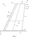
FIG. 2 is a side illustration of an airfoil system mounted to an aircraft assembly base. -
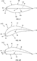
FIG. 3 is an illustration of a tip of the airfoil system with a symmetric configuration. -
FIGS. 4A and 4B are illustrations of the airfoil system tip with various asymmetric configurations. -
FIG. 5 is a perspective illustration of an airfoil segment of an airfoil body. -
FIG. 6 is a side illustration of an interior of the airfoil segment with a plurality of segment mounts schematically depicted. -
FIG. 7 is a cross-sectional illustration of the airfoil segment taken along section line 7-7 inFIG. 6 with its segment mounts schematically depicted. -
FIG. 8 is a cross-sectional illustration of an internal support connected to a portion of an exterior skin, where the segment mount for the internal support is schematically depicted. -
FIG. 9 is a partial illustration of the internal support with its segment mount schematically depicted. -
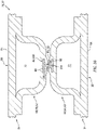
FIG. 10 is a cross-sectional illustration of a portion of the airfoil body depicting an interface connection between respective segment mounts. -
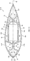
FIG. 11 is a cross-sectional illustration of the airfoil system with its segment mounts and an electric device schematically depicted. -
FIG. 12 is a sectional illustration of the airfoil system with its segment mounts and is electrical device schematically depicted. -
FIG. 13 is a cross-sectional illustration of a portion of the airfoil body depicting another interface connection between respective segment mounts. -
FIG. 14 is a flow diagram of a method for manufacturing the airfoil system. -
FIG. 1 illustrates a portion of anassembly 20 for an aircraft. Herein, the term "aircraft" may generally describe any mobile device which travels through at least air and/or space. The aircraft, for example, may be configured as an airplane, a helicopter, a spacecraft, a drone (e.g., an unmanned aerial vehicle (UAV)) or a projectile such as, but not limited to, a rocket. The present disclosure, however, is not limited to the foregoing exemplary aircraft configurations. - The
aircraft assembly 20 ofFIG. 1 includes abase 22 and anairfoil system 24. Theaircraft assembly base 22 may be any portion of the aircraft to which theairfoil system 24 may be mounted. Theaircraft assembly base 22, for example, may be configured as an exterior skin or other exterior structure of: an aircraft fuselage, an aircraft tail assembly, an aircraft wing, an engine pylon or a nacelle housing an aircraft engine. The present disclosure, however, is not limited to the foregoing exemplary aircraft assembly base configurations. - The
airfoil system 24 ofFIG. 1 is configured to at least partially or completely form an aerodynamic projection (e.g., a control element, a control surface, etc.) on theaircraft assembly base 22. Theairfoil system 24 ofFIG. 1 , for example, includes ahollow airfoil 26. Thisairfoil 26 may be configured as a wing, a vane, a fin and/or a vortex generator (e.g., a strake). Examples of the wing may include, but are not limited to, a winglet, a stub wing, a main wing, a tail wing and a stabilizer. - The
airfoil system 24 ofFIG. 1 is also configured as part of anelectronic system 28 of the aircraft such as, but not limited to, a communication system and/or a sensor system. Theairfoil system 24 ofFIG. 1 , for example, includes at least oneelectric device 30 configured with (e.g., housed within) theairfoil 26. Thiselectric device 30 may be configured as or otherwise include an antenna such as, but not limited to, a VHF antenna. Theelectric device 30 may also or alternatively be configured as or otherwise include a sensor such as, but not limited to, a prognostics and health management (PHM) sensor. The present disclosure, however, is not limited to the foregoing exemplary electric device configurations nor to communication or sensor system electric components. - Various types of electric devices may suffer from signal interference (e.g., signal loss and/or signal path obstruction) when housed within or otherwise surrounded by metal and/or conductive materials. To reduce or eliminate potential for such signal interference for the
electric device 30 ofFIG. 1 , theairfoil 26 is constructed substantially (or only) from non-metallic and/or dielectric material(s). More particularly, at least a significant portion of ahollow body 32 of theairfoil 26 that forms a housing and/or a shell about theelectric device 30 may be constructed substantially (or only) from the non-metallic and/or dielectric material(s). In addition, to facilitate placement of theelectric device 30 within theairfoil system 24 during assembly, theairfoil 26 may be configured with a segmented (e.g., clamshell-like) construction. However, to further reduce or eliminate potential for signal interference, theairfoil 26 may be configured without, for example, any traditional fasteners (e.g., bolts, screws, rivets, etc.) for securing itsairfoil segments airfoil 26 are described below in further detail. - The
airfoil system 24 ofFIG. 1 includes theairfoil 26 and anairfoil mount 36 configured to attach / secure theairfoil system 24 and itsairfoil 26 to theaircraft assembly base 22. Theairfoil system 24 ofFIG. 1 also includes theelectric device 30 configured (e.g., embedded, encapsulated and/or otherwise disposed) within theairfoil 26. However, in other embodiments, theairfoil system 24 may be configured without theelectric device 30 in order to provide the aerodynamic projection described herein without also being part of the aircraftelectronic system 28. Theairfoil 26, for example, may be configured to form a hollow aircraft control element without housing any electric devices therewithin. - The
airfoil 26 ofFIG. 1 is configured with / includes itshollow airfoil body 32. Theairfoil 26 ofFIG. 1 also includes a leading edge (LE)shield 38 configured to protect theairfoil body 32 at aleading edge 40 of theairfoil 26. - Referring to
FIG. 2 , theairfoil body 32 extends spanwise along a centerline 42 (e.g., a span line) of theairfoil 26 from a base 44 (e.g., a root) of theairfoil 26 to atip 46 of theairfoil 26. Referring toFIG. 3 , theairfoil body 32 extends lengthwise along acamber line 48 of theairfoil 26 from a leadingedge 50 of theairfoil body 32 to a trailingedge 52 of theairfoil 26, where the airfoilbody leading edge 50 is arranged at (e.g., on, adjacent or proximate) theairfoil leading edge 40. In the specific embodiment ofFIG. 3 , the airfoilbody leading edge 50 is slightly recessed inward from theairfoil leading edge 40 by a thickness of theshield 38. However, in other embodiments, the airfoilbody leading edge 50 may be on (e.g., the same as) theairfoil leading edge 40 where, for example, theshield 38 is omitted or incorporated as part of theairfoil body 32. Referring again toFIG. 3 , theairfoil body 32 extends widthwise (e.g., transverse to thecenterline 42 and/or the camber line 48) between and to opposing side exterior surfaces 54A and 54B (generally referred to as "54") of theairfoil body 32; e.g., exterior-most / outer-most surfaces of theairfoil body 32. Each of these airfoil body exterior surfaces 54 may be configured as a convex surface as shown inFIG. 3 . Alternatively, either one of the airfoil body exterior surfaces 54A or 54B may be a concave surface (seeFIG. 4A ) or a substantially flat surface (seeFIG. 4B ). - Referring to
FIGS. 2 and3 , theairfoil body 32 includes the plurality ofairfoil segments 34; e.g., a complimentary pair of airfoil segments. Theseairfoil segments 34 may be configured as respective halves of theairfoil body 32. Theairfoil segment 34A, for example, may form one half (or portion) of theairfoil body 32 on one side of theairfoil body 32; e.g., towards the airfoilbody exterior surface 54A. Theairfoil segment 34B, on the other hand, may form the other remaining half (or portion) of theairfoil body 32 on an opposing side of theairfoil body 32; e.g., towards the airfoilbody exterior surface 54B. Theairfoil segments 34 ofFIG. 3 have substantially identical (but, mirror image) configurations. The present disclosure, however, is not limited to such an exemplary identical, mirror image configuration. For example, referring toFIGS. 4A and 4B , theairfoil segments 34 may alternatively have different (but, still complementary) configurations. - Referring to
FIG. 5 , eachairfoil segment 34 extends spanwise along the centerline 42 from (or about) theairfoil base 44 to theairfoil tip 46. Eachairfoil segment 34 extends lengthwise along thecamber line 48 from the airfoil body leading edge 50 (or, alternatively the airfoil leading edge 40) to theairfoil trailing edge 52. Eachairfoil segment 34 extends widthwise from an interior side 56 (e.g., an intersegment mating side) of therespective airfoil segment 34 to the airfoilbody exterior surface 54 that is formed by thatrespective airfoil segment 34. - Referring to
FIGS. 6 and7 , eachairfoil segment 34 includes anexterior skin 58 and one or more (e.g., discrete or interconnected) internal supports 60-62. One or each of theairfoil segments 34 may also include anelectric device mount 64. - Referring to
FIG. 5 , theexterior skin 58 is configured to at least partially or completely form an exterior periphery of therespective airfoil segment 34. For example, theexterior skin 58 ofFIG. 5 (e.g., completely) forms its respective airfoilbody exterior surface 54. Theexterior skin 58 ofFIG. 5 also (e.g., partially) forms the airfoilbody leading edge 50, theairfoil trailing edge 52 and/or theairfoil tip 46. More particularly, theexterior skin 58 ofFIG. 5 extends spanwise from (or about) theairfoil base 44 to (or about) theairfoil tip 46, and lengthwise from (or about) the airfoilbody leading edge 50 to (or about) theairfoil trailing edge 52. A leading edge end of theexterior skin 58 may thereby at least partially form the airfoilbody leading edge 50. A trailing edge end of theexterior skin 58 may at least partially for theairfoil trailing edge 52. Theexterior skin 58 ofFIG. 5 also extends widthwise across theairfoil tip 46 to the airfoil segmentinterior side 56, and lengthwise across theairfoil tip 46 between and to theedges exterior skin 58 may thereby form a portion of theairfoil tip 46 that is carried by therespective airfoil segment 34. - Referring to
FIGS. 6 and7 , each of the internal supports 60-62 may be configured as an internal stiffener (e.g., a structural rib or other member) for supporting and providing rigidity to the respectiveexterior skin 58. Each of the internal supports 60-62, for example, is arranged on the airfoil segmentinterior side 56 and is connected to (e.g., formed integral with) the respectiveexterior skin 58. - Referring to
FIG. 6 , the leading edge (LE)support 60 is arranged at (e.g., on, adjacent or proximate) the airfoilbody leading edge 50. ThisLE support 60 extends spanwise between and to (or about) theairfoil base 44 and theairfoil tip 46. The trailing edge (TE)support 61 is arranged at (e.g., on, adjacent or proximate) theairfoil trailing edge 52. ThisTE support 61 extends spanwise between and to (or about) theairfoil base 44 and theairfoil tip 46. Theintermediate support 62 is arranged intermediately (e.g., about midway) spanwise along thecenterline 42 between theairfoil base 44 and theairfoil tip 46. Thisintermediate support 62 extends lengthwise between and to (or about) theLE support 60 and theTE support 61. - Referring to
FIG. 8 , each of the internal supports 60-62 may have a channeled and/or tubular configuration; e.g., a hat or top-hat configuration. Eachinternal support internal support FIG. 8 . The present disclosure, of course, is not limited to the foregoing exemplary internal support configurations. - Each
internal support internal sidewalls 66 and 68 (e.g., structural flanges) and an internal endwall 70 (e.g., a structural web). Thesesupport elements internal support internal support channel 72. Thischannel 72 extends longitudinally along the longitudinal centerline of the respective internal support, where thechannel 72 ofFIG. 8 is closed off by an interior peripheral portion of theexterior skin 58 of therespective airfoil segment 34. Eachinternal support outward lips 74 and 76 (or inward lips) for fixing theinternal support exterior skin 58. - The
internal support members FIG. 8 are integrally connected together, and eachinternal support exterior skin 58 as described below in further detail. Each of theinternal support members internal support - The
first sidewall 66 is connected to the respectiveexterior skin 58 at an interior of therespective airfoil segment 34 via, for example, thefirst lip 74. In particular, thefirst lip 74 is connected to and projects out (e.g., in a first direction away from the channel 72) from thefirst sidewall 66. Thefirst lip 74 ofFIG. 8 extends along and is connected to the respectiveexterior skin 58. Thefirst sidewall 66 projects inward from the respectiveexterior skin 58 and thefirst lip 74 to adistal end 78 of the respectiveinternal support - The
second sidewall 68 is connected to the respectiveexterior skin 58 at the interior of therespective airfoil segment 34 via, for example, thesecond lip 76. In particular, thesecond lip 76 is connected to and projects out (e.g., in a second direction away from thechannel 72 that is opposite the first direction) from thesecond sidewall 68. Thesecond lip 76 ofFIG. 8 extends along and is connected to the respectiveexterior skin 58. Thesecond sidewall 68 projects inward from the respectiveexterior skin 58 and thesecond lip 76 to thedistal end 78 of the respectiveinternal support - The
endwall 70 is arranged at (e.g., on, adjacent or proximate) thedistal end 78 of the respectiveinternal support endwall 70 ofFIG. 8 is connected to and extends between thefirst sidewall 66 and thesecond sidewall 68. With this arrangement, theinternal support channel 72 extends between and to the respectiveexterior skin 58 and theendwall 70. Theinternal support channel 72 also extends between and to the opposingsidewalls - Each
internal support FIGS. 6-9 . Referring toFIG. 9 , eachsegment mount 80 may extend longitudinally along the respectiveinternal support longitudinal length 82 of thesegment mount 80 may be equal to or less than alongitudinal length 84 of the respectiveinternal support segment mount length 82 may be greater than fifty percent (50%), sixty percent (60%), seventy percent (70%), eighty percent (80%) or ninety percent (90%) of theinternal support length 84, but equal to or less than theinternal support length 84. In some embodiments, thesegment mount 80 may extend uninterrupted along its entirelongitudinal length 82. In other embodiments, thesegment mount 80 may be longitudinally interrupted; e.g., cut, formed by multiple spaced (or abutted) segments represented by dashedlines 86 inFIG. 9 , etc. - Referring to
FIG. 8 , thesegment mount 80 is connected to (e.g., formed integral with) therespective endwall 70. Abase 88 of thesegment mount 80, for example, may be embedded within (or otherwise configured with and/or coupled to) material of therespective endwall 70. Afirst portion 90 of the endwall material inFIG. 8 , for example, overlaps afirst side 92 of thesegment mount base 88. The basefirst side 92 is thereby captured (e.g., sandwiched) between and secured (e.g., bonded) to thefirst portion 90 of the endwall material and abase portion 94 of the endwall material. In addition, asecond portion 96 of the endwall material inFIG. 8 overlaps asecond side 98 of thesegment mount base 88. The basesecond side 98 is thereby captured (e.g., sandwiched) between and secured (e.g., bonded) to thesecond portion 96 of the endwall material and thebase portion 94 of the endwall material. - An
interface 100 of thesegment mount 80 is connected to (e.g., formed integral with) and projects out from thesegment mount base 88 to a distal end of thesegment mount interface 100 / thesegment mount 80. Thissegment mount interface 100 is configured to mate with another one of the segment mount interfaces 100 configured with the correspondinginternal support airfoil segment 34. For example, referring toFIG. 10 , one of the segment mounts 80 may be configured as a receptacle 102 with areceptacle aperture 104; e.g., a channel, a slot, a groove, etc. The other one of the segment mounts 80 may be configured as a key 106 with akey protrusion 108; e.g., a rib, a rail, a rim, etc. With such an arrangement, when the key 106 mates with the receptacle 102, thekey protrusion 108 may project into thereceptacle aperture 104 to provide an inter-locking (e.g., tongue-and-groove) interface between the respective segment mounts 80. The key 106 and itsprotrusion 108 may also be attached (e.g., bonded) to the receptacle 102 to fixedly secure the engaged (e.g., interlocked) segment mounts 80 together. - Referring again to
FIGS. 6 and7 , theelectric device mount 64 is arranged at the interior of therespective airfoil segment 34. Theelectric device mount 64 ofFIGS. 6 and7 , for example, is arranged lengthwise between theLE support 60 and theTE support 61. Thiselectric device mount 64 is also arranged spanwise between theintermediate support 62 and theairfoil tip 46. Referring toFIG. 7 , theelectric device mount 64 may be spaced from the respectiveexterior skin 58 by a (e.g., air)gap 110. - The
electric device mount 64 may be connected to (e.g., formed integral with) one or more or each of the internal supports 60-62 of therespective airfoil segment 34. Theelectric device mount 64, for example, may extend lengthwise between and to theLE support 60 and theTE support 61. As best seen inFIG. 6 , theelectric device mount 64 may also or alternatively project out from theintermediate support 62 towards theairfoil tip 46. - The
electric device mount 64 may be configured as an internal mounting tray. Theelectric device mount 64 ofFIGS. 6 and7 , for example, has a generally plate-like configuration. - Referring to
FIGS. 11 and12 , theairfoil body 32 is formed by attaching theairfoil segments 34 together. The edges of theexterior skins 58 are aligned, for example, and may be attached (e.g., bonded) together using bonding material such as resin or any other adhesive, and/or joined via a sealant material. Internal support structures (e.g., networks of the internal supports 60-62) of theairfoil segments 34 are also aligned and may be attached (e.g., bonded) together using bonding material such as resin or any other adhesive. For example, theLE support 60 of one of theairfoil segments 34A is aligned with theLE support 60 of the other one of theairfoil segments 34B. The segment mounts 80 of those LE supports 60 are mated and/or secured together as described above; e.g., seeFIG. 10 . TheTE support 61 of one of theairfoil segments 34A is aligned with theTE support 61 of the other one of theairfoil segments 34B. The segment mounts 80 of those TE supports 61 are mated and/or secured together as described above; e.g., seeFIG. 10 . Theintermediate support 62 of one of theairfoil segments 34A is aligned with theintermediate support 62 of the other one of theairfoil segments 34B. The segment mounts 80 of thoseintermediate supports 62 are mated and/or secured together as described above; e.g., seeFIG. 10 . With such an arrangement, theairfoil segments 34 may be connected together without, for example, use of any traditional (e.g., metal and/or otherwise) fasteners; e.g., bolts, screws, rivets, etc. Theairfoil body 32 may therefore be a fastener-free body. - The
airfoil body 32 is configured with one or more internal cavities 112-115. Referring toFIG. 11 , the leading edge (LE)cavity 112 is arranged at the airfoilbody leading edge 50. ThisLE cavity 112 is formed collectively by the joinedexterior skins 58 and the joined LE supports 60. TheLE cavity 112, for example, extends lengthwise within theairfoil body 32 from the joinedexterior skins 58 to the joined LE supports 60. TheLE cavity 112 extends widthwise within theairfoil body 32 between the opposing exterior skins 58. TheLE cavity 112 extends spanwise within theairfoil body 32, and along the airfoilbody leading edge 50, from (or about) theairfoil base 44 to the joinedexterior skins 58 at theairfoil tip 46; see alsoFIG. 6 . - The trailing edge (TE)
cavity 113 is arranged at theairfoil trailing edge 52. ThisTE cavity 113 is formed collectively by the joinedexterior skins 58 and the joined TE supports 61. TheTE cavity 113, for example, extends lengthwise within theairfoil body 32 from the joinedexterior skins 58 to the joined TE supports 61. TheTE cavity 113 extends widthwise within theairfoil body 32 between the opposing exterior skins 58. TheTE cavity 113 extends spanwise within theairfoil body 32, and along theairfoil trailing edge 52, from (or about) theairfoil base 44 to the joinedexterior skins 58 at theairfoil tip 46; see alsoFIG. 6 . - Referring to
FIGS. 6 and12 , theinner cavity 114 is arranged at theairfoil base 44. Thisinner cavity 114 is formed collectively by the joinedexterior skins 58, the joined LE supports 60, the joined TE supports 61 and the joined intermediate supports 62. Theinner cavity 114, for example, extends lengthwise within theairfoil body 32 from the joined LE supports 60 to the joined TE supports 61. Theinner cavity 114 extends widthwise within theairfoil body 32 between the opposing exterior skins 58. Theinner cavity 114 extends spanwise within theairfoil body 32 from (or about) theairfoil base 44 to the joined intermediate supports 62. - Referring to
FIGS. 11 and12 , the outer (e.g., electric device)cavity 115 is arranged at theairfoil tip 46. Thisouter cavity 115 is formed collectively by the joinedexterior skins 58, the joined LE supports 60, the joined TE supports 61, the joinedintermediate supports 62 and the electric device mounts 64. Theouter cavity 115, for example, extends lengthwise within theairfoil body 32 from the joined LE supports 60 (e.g., a leading edge (LE) end of the outer cavity 115) to the joined TE supports 61 (e.g., a trailing edge (TE) end of the outer cavity 115). Theouter cavity 115 extends widthwise within theairfoil body 32 between the opposingexterior skins 58 and/or the opposing electric device mounts 64; e.g., between opposing sides of theouter cavity 115. Theouter cavity 115 extends spanwise within theairfoil body 32 from the joined intermediate supports 62 (e.g., a lower, base end of the outer cavity 115) to the joinedexterior skins 58 at the airfoil tip 46 (e.g., an upper, tip end of the outer cavity 115). - The
outer cavity 115 ofFIGS. 11 and12 is configured (e.g., shaped and sized) to at least partially or completely receive theelectric device 30 therewith. Theelectric device 30 may thereby be arranged within the outer cavity 115 (prior to assembly and attachment of the airfoil segments 34). Theelectric device 30 may be secured within theairfoil body 32 by attaching theelectric device 30 to one or each of theairfoil segments 34. Theelectric device 30 ofFIGS. 11 and12 , for example, may be attached (e.g., bonded) to one or each of the opposing electric device mounts 64 using bonding material such as resin or any other adhesive. - The
shield 38 ofFIG. 11 is configured to protect the airfoilbody leading edge 50 from foreign object damage (FOD), erosion and/or other damage. Theshield 38, for example, may be formed from a durable material such as metal; e.g., nickel (Ni). Theshield 38 is attached to theairfoil body 32. A leading edge portion of theairfoil body 32, for example, is inserted into an internal channel of theshield 38 such that aninterior surface 118 of theshield 38 is engaged with (e.g., abutted against) an exterior (e.g., the surfaces 54) of theairfoil body 32 at its leadingedge 50. Theshield 38 may be attached (e.g., bonded) to theairfoil body 32 and itsexterior skins 58 using bonding material such as resin or any other adhesive. - Referring to
FIG. 1 , theshield 38 may extend along a majority (e.g., at least 80-90%) or an entirety of the airfoilbody leading edge 50. Theshield 38 ofFIG. 1 may thereby at least partially or completely form theairfoil leading edge 40. Theshield 38 also forms leading edge portions of opposingexterior surfaces airfoil 26. The remaining portions (and substantially a majority) of the opposing airfoil exterior surfaces 120 are formed by exposed portions of theexterior skins 58 and their exterior surfaces 54. The exterior skins 58 of theairfoil body 32 are thereby arranged at and may at least partially form (or completely form where theshield 38 is omitted) the opposing airfoil exterior surfaces 120. - Referring still to
FIG. 1 , theairfoil mount 36 is arranged at theairfoil base 44. Theairfoil mount 36 is connected to (e.g., formed integral with) theairfoil body 32. The airfoil mount 36 ofFIG. 1 , for example, includes one ormore flanges FIG. 12 . Each of these flanges 122 is connected to and projects outward from a respective one of the exterior skins 58. Theairfoil mount 36 and its flanges 122 are connected (e.g., mechanically fastened, bonded and/or otherwise attached) to theaircraft assembly base 22 to fixedly secure theairfoil system 24 and itsairfoil 26 to theaircraft assembly base 22. Theairfoil mount 36, for example, may be mechanically fastened to theaircraft assembly base 22 using one ormore fasteners 124, and/or bonded using bonding material such as resin or any other adhesive. - The
airfoil body 32 and itsairfoil segments 34 may be constructed substantially (or only) from the non-metallic and/or dielectric material(s). In particular, theairfoil body 32 and itsairfoil segments 34 may be constructed substantially (or only) from composite material such as, but not limited to, non-metallic fiber reinforcement within a matrix. An example of the non-metallic fiber reinforcement is, but is not limited to, fiberglass. An example of the matrix is, but is not limited to, polymer (e.g., thermoplastic or thermoset) resin. - Referring to
FIGS. 11 and12 , eachairfoil segment 34 and itsvarious components 58, 60-62 and 64 may be formed together as a single, monolithic body. Herein, the term "monolithic" may described a single, unitary body formed (e.g., resin pressure molded (RPM), resin transfer molded (RTM) or otherwise constructed) as a single collective mass of material. For example, while the segment mounts 80 may be constructed from material that is different than the material (e.g., the non-metallic and/or dielectric material(s)) of the remainder theirrespective airfoil segment 34, eachsegment mount 80 may be laid up integrally with and incorporated with the other material during the formation process. The term "monolithic" may also describe herein a single, unitary body formed from discrete elements that are permanently attached together via, for example, fusion, welding and/or an adhesive (e.g., epoxy resin). A non-monolithic body, by contrast, includes discretely formed bodies which are removably attached together; e.g., mechanically fastened together, brazed together, etc. - As described above, the segment mounts 80 may be constructed from material that is different than the remainder their
respective airfoil segment 34. Eachsegment mount 80, for example, may be constructed from metal such as, but not limited to, aluminum (Al). Thus, while the non-metallic and/or dielectric material(s) is selected to reduce signal interference for theelectric device 30 and/or airfoil reduce weight, the segment mount material may be selected to provide a more robust, rigid, precise connection between theairfoil segments 34. Of course, in other embodiments, one or more of the segment mounts 80 may be constructed from composite material (e.g., non-metallic material), which composite material may be the same or different than the material forming the remainder of therespective airfoil segment 34. In still other embodiments, one or more respective pairs of the segment mounts 80 may be omitted as shown, for example, inFIG. 13 . One or more of respective sets ofendwalls 70, for example, may be joined directly together via, for example, an adhesive butt connection. - Each
airfoil segment 34 may be formed using resin pressure molding (RPM), resin transfer molding (RTM) and/or various other molding process. For example, one or more plies of reinforcement material (e.g., fiberglass) may be arranged within a mold. By using one or more mandrels, the reinforcement material may be arranged to form a preform (e.g., a body having a general shape) of therespective airfoil segment 34 and each of itsmembers 58, 60-62 and 64. In addition, the respective segment mounts 80 may also be laid up with the reinforcement material (e.g., between the plies) such that thosemounts 80 are formed integral with theairfoil segment 34; e.g., seeFIGS. 8 and10 . The mold may then be closed, and resin may be injected into the closed mold under pressure to infiltrate the reinforcement material and form a matrix in which the reinforcements material is embedded. The resin may then be cured under elevated pressure and/or an elevated temperature. Following this curing, the mandrels are removed from theairfoil segment 34 and theairfoil segment 34 is removed from the mold. Eachairfoil segment 34 may thereby be integrally formed using a single molding process. This may reduce complexity and/or costs of airfoil manufacture. The present disclosure, however, is not limited to the foregoing exemplary manufacturing techniques. -
FIG. 14 is a flow diagram of amethod 1400 for manufacturing an airfoil system such as theairfoil system 24 described above. Instep 1402, each of theairfoil segments 34 is provided. Eachairfoil segment 34, for example, may be formed as described above using resin pressure molding (RPM), resin transfer molding (RTM) and/or various other molding process. - In
step 1404, theelectric device 30 is attached to a first of the airfoil segment (e.g., 34A). Theelectric device 30, for example, may be attached (e.g., bonded) to theelectric device mount 64 of the first airfoil segment (e.g., 34A). - In
step 1406, theairfoil body 32 is assembled. Bonding material, for example, may be applied to one or more mating portions of one or both of theairfoil segments 34. Theairfoil segments 34 may then be aligned and mated as described above such that the bonding material attaches theairfoil segments 34 together. Additional bonding material may also be applied to further secure theelectric device 30 to the second airfoil segment (e.g., 34B) and itselectric device mount 64. - In step 1408, the
shield 38 is configured with theairfoil body 32 to provide theairfoil 26. Theairfoil body 32, for example, may be mated with and attached to theshield 38 as described above. - In some embodiments, the
method 1400 may be modified to include one or more additional steps and/or to omit one or more of the foregoing steps. For example, themethod 1400 may include one or more formation (e.g., machining, cutting, etc.) processes and/or one or more finishing (e.g., sanding, treating, coating, etc.) processes. Themethod 1400 may also or alternatively omit thestep 1404 and/or the step 1408 where, for example, theairfoil 26 is configured without theelectric device 30 and/or theshield 38. - The
airfoil body 32 and itsairfoil segments 34 may be constructed substantially (or only) from the non-metallic and/or dielectric material(s) as described above. However, in other embodiments, the internal support structure / airfoil frame (e.g., theinternal supports exterior skin 58 material. For example, the exterior skins 58 may be constructed from the non-metallic and/or dielectric material, whereas one or more of theinternal supports exterior skins 58 in, for example, a similar manner as described above with respect to the segment mounts 80. In such embodiments, eachsegment mount 80 may be formed with a respective one of theinternal supports internal supports - While various embodiments of the present invention have been disclosed, it will be apparent to those of ordinary skill in the art that many more embodiments and implementations are possible within the scope of the invention. For example, the present invention as described herein includes several aspects and embodiments that include particular features. Although these features may be described individually, it is within the scope of the present invention that some or all of these features may be combined with any one of the aspects and remain within the scope of the invention. Accordingly, the present invention is not to be restricted except in light of the attached claims and their equivalents.
Claims (15)
- An airfoil system (24), comprising:an airfoil (26) comprising a first exterior surface (54A), a second exterior surface (54B), a first airfoil segment (34A) and a second airfoil segment (34B) attached to the first airfoil segment (34A), the airfoil (26) extending widthwise between the first exterior surface (54A) and the second exterior surface (54B), the first airfoil segment (34A) forming the first exterior surface (54A), and the second airfoil segment (34B) forming the second exterior surface (54B); andan electric device (30) embedded within the airfoil (26) between the first airfoil segment (34A) and the second airfoil segment (34B).
- The airfoil system (24) of claim 1, wherein:the electric device (30) comprises an antenna; and/orthe electric device (30) comprises a sensor; and/orthe electric device (30) is attached to at least one of the first airfoil segment (34A) or the second airfoil segment (34B).
- The airfoil system (24) of claim 1 or 2, whereinthe airfoil (26) further comprises an internal cavity (115) formed collectively by the first airfoil segment (34A) and the second airfoil segment (34B); andthe electric device (30) is located within the internal cavity (115).
- The airfoil system (24) of claim 3, whereinthe internal cavity (115) extends widthwise within the airfoil (26) between a first cavity side (58, 64) and a second cavity side (58, 64);the first airfoil segment (34A) forms the first cavity side (58, 64); andthe second airfoil segment (34B) forms the second cavity side (58, 64).
- The airfoil system (24) of claim 3 or 4, whereinthe internal cavity (115) extends lengthwise within the airfoil (26) between a cavity leading end (60) and a cavity trailing end (61);the first airfoil segment (34A) forms a first portion of the cavity leading end (60) and a first portion of the cavity trailing end (61); andthe second airfoil segment (34B) forms a second portion of the cavity leading end (60) and a second portion of the cavity trailing end (61).
- The airfoil system (24) of claim 3, 4, or 5, whereinthe internal cavity (115) extends spanwise within the airfoil (26) between a cavity base end (62) and a cavity tip end (46);the first airfoil segment (34A) forms a first portion of the cavity base end (62) and a first portion of the cavity tip end (46); andthe second airfoil segment (34B) forms a second portion of the cavity base end (62) and a second portion of the cavity tip end (46).
- The airfoil system (24) of any preceding claim, whereinthe first airfoil segment (34A) comprises a first exterior skin (58) that forms the first exterior surface (54A);the second airfoil segment (34B) comprises a second exterior skin (58) that forms the second exterior surface (54A); andthe first exterior skin (58) and the second exterior skin (58) each comprises composite material.
- The airfoil system (24) of any of claims 1 to 6, whereinthe first airfoil segment (34A) comprises a first exterior skin (58) and a first internal support (60, 61, 62) formed integral with the first exterior skin (58), and the first exterior skin (58) forms the first exterior surface (54A);the second airfoil segment (34B) comprises a second exterior skin (58) and a second internal support (60, 61, 62) formed integral with the second exterior skin (58), and the second exterior skin (58) forms the second exterior surface (54B); andthe first internal support (60, 61, 62) engages and is attached to the second internal support (60, 61, 62), wherein the first internal support (60, 61, 62) is optionally abutted against and bonded to the second internal support (60, 61, 62).
- The airfoil system (24) of claim 8, whereinthe first internal support (60, 61, 62) comprises a receptacle (102); andthe second internal support (60, 61, 62) comprises a key (106) that is mated with the receptacle (102).
- The airfoil system (24) of any preceding claim, whereinthe airfoil (26) comprises an airfoil body (32);the first airfoil segment (34A) is a first half of the airfoil body (32); andthe second airfoil segment (34B) is a second half of the airfoil body (32).
- The airfoil system (24) of any preceding claim, whereinthe airfoil (26) further comprises a shield (38);the shield (38) is configured at and extends spanwise along a leading edge (40) of the airfoil (26); andthe shield (38) overlaps and is attached to a first leading edge portion of the first airfoil segment (34A) and a second leading edge portion of the second airfoil segment (34B).
- An airfoil system (24), comprising:an airfoil body (32) comprising a first airfoil segment (34A) and a second airfoil segment (34B) attached to the first airfoil segment (34A), the first airfoil segment (34A) comprising a first composite material and forming a first half of the airfoil body (32), the second airfoil segment (34B) comprising a second composite material and forming a second half of the airfoil body (32), wherein, optionally, at least one of the first composite material or the second composite material comprises fiberglass reinforcement within a resin matrix; andan electric device (30) located within an internal cavity (115) of the airfoil body (32) between the first airfoil segment (34A) and the second airfoil segment (34B).
- The airfoil system of claim 12, further comprising:an airfoil (26) comprising a first exterior surface (54A), a second exterior surface (54B) and the airfoil body (32), the airfoil (26) extending widthwise between the first exterior surface (54A) and the second exterior surface (54B);the first airfoil segment (34A) forming the first exterior surface (54A); andthe second airfoil segment (34B) forming the second exterior surface (54B).
- A manufacturing method, comprising:forming a first airfoil segment (34A) as a first monolithic body;forming a second airfoil segment (34B) as a second monolithic body;attaching an electric device (30) to the first airfoil segment (34A); andattaching the second airfoil segment (34B) to the first airfoil segment (34A) to provide an airfoil body (32), wherein the electric device (30) is embedded within the airfoil body (32) between the first airfoil segment (34A) and the second airfoil segment (34B),wherein, optionally, the first airfoil segment (34A) and the second airfoil segment (34B) each comprise non-metallic material.
- The manufacturing method of claim 14, further comprising:
attaching a shield (38) to the airfoil body (32) to form a leading edge of an airfoil (26); wherein the airfoil (26) includes the airfoil body (32) and the shield (38).
Applications Claiming Priority (1)
| Application Number | Priority Date | Filing Date | Title |
|---|---|---|---|
| US17/240,129 US12116121B2 (en) | 2021-04-26 | 2021-04-26 | Airfoil system with embedded electric device |
Publications (2)
| Publication Number | Publication Date |
|---|---|
| EP4082894A1 true EP4082894A1 (en) | 2022-11-02 |
| EP4082894B1 EP4082894B1 (en) | 2024-09-25 |
Family
ID=81387063
Family Applications (1)
| Application Number | Title | Priority Date | Filing Date |
|---|---|---|---|
| EP22170106.3A Active EP4082894B1 (en) | 2021-04-26 | 2022-04-26 | Airfoil system with embedded electric device |
Country Status (2)
| Country | Link |
|---|---|
| US (1) | US12116121B2 (en) |
| EP (1) | EP4082894B1 (en) |
Families Citing this family (1)
| Publication number | Priority date | Publication date | Assignee | Title |
|---|---|---|---|---|
| US11952119B2 (en) * | 2021-05-05 | 2024-04-09 | Beirobotics Llc | Payload support frame for unmanned aerial system |
Citations (5)
| Publication number | Priority date | Publication date | Assignee | Title |
|---|---|---|---|---|
| US20080042011A1 (en) * | 2006-08-16 | 2008-02-21 | Airbus Uk Limited | Cover panel for an aircraft wing and a method of forming thereof |
| US20130016019A1 (en) * | 2011-07-15 | 2013-01-17 | The Boeing Company | Integrated Antenna System |
| US20140159965A1 (en) * | 2012-07-18 | 2014-06-12 | P-Wave Holdings Llc | Broadband aircraft wingtip antenna system |
| US20190176957A1 (en) * | 2017-12-12 | 2019-06-13 | The Boeing Company | Core structures for composite panels of an aircraft, composite panels and aircraft including the core structures, and methods of manufacturing the composite panels |
| WO2020260311A1 (en) * | 2019-06-28 | 2020-12-30 | Airbus Operations Gmbh | Antenna assembly, vertical tail, horizontal tail, wing, aircraft, and method |
Family Cites Families (21)
| Publication number | Priority date | Publication date | Assignee | Title |
|---|---|---|---|---|
| US4072952A (en) * | 1976-10-04 | 1978-02-07 | The United States Of America As Represented By The Secretary Of The Army | Microwave landing system antenna |
| DE3014347C2 (en) | 1980-04-15 | 1983-05-26 | Messerschmitt-Bölkow-Blohm GmbH, 8000 München | Process for the production of foam core-supported, fiber-reinforced plastic moldings such as blades, rotor blades, etc., of great length and width |
| US4509053A (en) | 1982-07-26 | 1985-04-02 | Sensor Systems, Inc. | Blade antenna with shaped dielectric |
| US6097343A (en) | 1998-10-23 | 2000-08-01 | Trw Inc. | Conformal load-bearing antenna system that excites aircraft structure |
| US7205066B1 (en) | 2002-05-23 | 2007-04-17 | Rohr, Inc. | Structural element with rib-receiving member |
| US7238409B1 (en) * | 2002-05-23 | 2007-07-03 | Rohr, Inc. | Structural element with rib-receiving member |
| US20110211965A1 (en) | 2010-02-26 | 2011-09-01 | United Technologies Corporation | Hollow fan blade |
| EP2585370B1 (en) * | 2010-06-22 | 2016-06-01 | Sikorsky Aircraft Corporation | Erosion resistant helicopter blade |
| US9233414B2 (en) | 2012-01-31 | 2016-01-12 | United Technologies Corporation | Aluminum airfoil |
| US9019161B1 (en) | 2012-03-21 | 2015-04-28 | Rockwell Collins, Inc. | Tri-fin TCAS antenna |
| FR2989723B1 (en) | 2012-04-20 | 2024-02-09 | Astrium Sas | ASSEMBLY OF STRUCTURES OF STRUCTURAL PARTS |
| US9457886B2 (en) | 2013-06-25 | 2016-10-04 | Sierra Nevada Corporation | Integral antenna winglet |
| WO2015051803A1 (en) | 2013-10-10 | 2015-04-16 | Vestas Wind Systems A/S | Wind turbine blade |
| US10167550B2 (en) * | 2014-06-03 | 2019-01-01 | Aurora Flight Sciences Corporation | Multi-functional composite structures |
| FR3024293B1 (en) | 2014-07-25 | 2017-12-01 | Airbus Operations Sas | ANTENNA SYSTEM FOR AN AIRCRAFT |
| US9527238B2 (en) | 2015-03-13 | 2016-12-27 | Rohr, Inc. | Method of manufacturing thrust reverser cascades |
| US11046034B2 (en) | 2016-04-18 | 2021-06-29 | Rohr, Inc. | Manufacturing a fiber-reinforced composite component using mandrels |
| RO132984A1 (en) | 2017-06-09 | 2018-12-28 | Octav Alexan | Wing structures with sinusoidal elements |
| US10933973B2 (en) * | 2018-04-26 | 2021-03-02 | Solaero Technologies Corp. | Airfoil body |
| US10848189B2 (en) | 2018-07-25 | 2020-11-24 | The Boeing Company | Method for curing and embedding an antenna in a composite part |
| US11248477B2 (en) | 2019-08-02 | 2022-02-15 | Raytheon Technologies Corporation | Hybridized airfoil for a gas turbine engine |
-
2021
- 2021-04-26 US US17/240,129 patent/US12116121B2/en active Active
-
2022
- 2022-04-26 EP EP22170106.3A patent/EP4082894B1/en active Active
Patent Citations (5)
| Publication number | Priority date | Publication date | Assignee | Title |
|---|---|---|---|---|
| US20080042011A1 (en) * | 2006-08-16 | 2008-02-21 | Airbus Uk Limited | Cover panel for an aircraft wing and a method of forming thereof |
| US20130016019A1 (en) * | 2011-07-15 | 2013-01-17 | The Boeing Company | Integrated Antenna System |
| US20140159965A1 (en) * | 2012-07-18 | 2014-06-12 | P-Wave Holdings Llc | Broadband aircraft wingtip antenna system |
| US20190176957A1 (en) * | 2017-12-12 | 2019-06-13 | The Boeing Company | Core structures for composite panels of an aircraft, composite panels and aircraft including the core structures, and methods of manufacturing the composite panels |
| WO2020260311A1 (en) * | 2019-06-28 | 2020-12-30 | Airbus Operations Gmbh | Antenna assembly, vertical tail, horizontal tail, wing, aircraft, and method |
Also Published As
| Publication number | Publication date |
|---|---|
| EP4082894B1 (en) | 2024-09-25 |
| US20220340253A1 (en) | 2022-10-27 |
| US12116121B2 (en) | 2024-10-15 |
Similar Documents
| Publication | Publication Date | Title |
|---|---|---|
| EP4084215A1 (en) | Airfoil system with embedded electric device | |
| KR102414000B1 (en) | Conformal composite antenna assembly | |
| KR100468508B1 (en) | A composite tip cap assembly for a helicopter main rotor blade | |
| EP2824030B1 (en) | Apparatus and methods for joining composite structures of aircrafts | |
| US9248900B2 (en) | Tip fairing of a horizontal airfoil of an aircraft | |
| US10239602B2 (en) | Multi-spar torsion box structure | |
| EP3584152B1 (en) | Method for manufacturing a multi-spar box with a continuous skin upper shell of a tail cone section for a rear end of an aircraft and a composite assembly | |
| EP2452872B1 (en) | Fuselage employing multifunctional crown and method of making the same | |
| US2400649A (en) | Molded airfoil, especially for sustaining rotors | |
| US20010013173A1 (en) | Method of fabricating leading edge nose structures of aerodynamic surfaces | |
| US10501163B2 (en) | Pressure bulkhead for an aircraft fuselage, and an aircraft comprising such a pressure bulkhead | |
| US11843164B2 (en) | Antenna assembly, vertical tail, horizontal tail, wing, aircraft, and method | |
| US20190016436A1 (en) | Stringer with plank ply and skin construction for aircraft | |
| CN113602477B (en) | Tail wing structure made of full composite material and forming method thereof | |
| EP4082894B1 (en) | Airfoil system with embedded electric device | |
| CN113365912A (en) | Aircraft assembly with integrated spar-cap | |
| CN113382925A (en) | Rib mounting assembly | |
| US12539976B2 (en) | Nacelle inlet assembly with acoustic panel | |
| US11319052B2 (en) | Leading-edge arrangement for a flow body of a vehicle | |
| CN210653691U (en) | A fairing and aerospace vehicle | |
| US11724792B2 (en) | Composite airfoil for an aircraft | |
| US12043385B2 (en) | Aircraft control surface having variable height corrugated core | |
| CN217918385U (en) | Covering, wing and unmanned aerial vehicle | |
| JPH1114299A (en) | Flying object wing | |
| CN116215837B (en) | Unmanned aerial vehicle |
Legal Events
| Date | Code | Title | Description |
|---|---|---|---|
| PUAI | Public reference made under article 153(3) epc to a published international application that has entered the european phase |
Free format text: ORIGINAL CODE: 0009012 |
|
| STAA | Information on the status of an ep patent application or granted ep patent |
Free format text: STATUS: THE APPLICATION HAS BEEN PUBLISHED |
|
| AK | Designated contracting states |
Kind code of ref document: A1 Designated state(s): AL AT BE BG CH CY CZ DE DK EE ES FI FR GB GR HR HU IE IS IT LI LT LU LV MC MK MT NL NO PL PT RO RS SE SI SK SM TR |
|
| STAA | Information on the status of an ep patent application or granted ep patent |
Free format text: STATUS: REQUEST FOR EXAMINATION WAS MADE |
|
| 17P | Request for examination filed |
Effective date: 20230502 |
|
| RBV | Designated contracting states (corrected) |
Designated state(s): AL AT BE BG CH CY CZ DE DK EE ES FI FR GB GR HR HU IE IS IT LI LT LU LV MC MK MT NL NO PL PT RO RS SE SI SK SM TR |
|
| GRAP | Despatch of communication of intention to grant a patent |
Free format text: ORIGINAL CODE: EPIDOSNIGR1 |
|
| STAA | Information on the status of an ep patent application or granted ep patent |
Free format text: STATUS: GRANT OF PATENT IS INTENDED |
|
| INTG | Intention to grant announced |
Effective date: 20240424 |
|
| GRAS | Grant fee paid |
Free format text: ORIGINAL CODE: EPIDOSNIGR3 |
|
| GRAA | (expected) grant |
Free format text: ORIGINAL CODE: 0009210 |
|
| STAA | Information on the status of an ep patent application or granted ep patent |
Free format text: STATUS: THE PATENT HAS BEEN GRANTED |
|
| AK | Designated contracting states |
Kind code of ref document: B1 Designated state(s): AL AT BE BG CH CY CZ DE DK EE ES FI FR GB GR HR HU IE IS IT LI LT LU LV MC MK MT NL NO PL PT RO RS SE SI SK SM TR |
|
| REG | Reference to a national code |
Ref country code: GB Ref legal event code: FG4D |
|
| REG | Reference to a national code |
Ref country code: CH Ref legal event code: EP |
|
| REG | Reference to a national code |
Ref country code: DE Ref legal event code: R096 Ref document number: 602022006300 Country of ref document: DE |
|
| REG | Reference to a national code |
Ref country code: IE Ref legal event code: FG4D |
|
| REG | Reference to a national code |
Ref country code: LT Ref legal event code: MG9D |
|
| PG25 | Lapsed in a contracting state [announced via postgrant information from national office to epo] |
Ref country code: NO Free format text: LAPSE BECAUSE OF FAILURE TO SUBMIT A TRANSLATION OF THE DESCRIPTION OR TO PAY THE FEE WITHIN THE PRESCRIBED TIME-LIMIT Effective date: 20241225 |
|
| PG25 | Lapsed in a contracting state [announced via postgrant information from national office to epo] |
Ref country code: GR Free format text: LAPSE BECAUSE OF FAILURE TO SUBMIT A TRANSLATION OF THE DESCRIPTION OR TO PAY THE FEE WITHIN THE PRESCRIBED TIME-LIMIT Effective date: 20241226 Ref country code: FI Free format text: LAPSE BECAUSE OF FAILURE TO SUBMIT A TRANSLATION OF THE DESCRIPTION OR TO PAY THE FEE WITHIN THE PRESCRIBED TIME-LIMIT Effective date: 20240925 |
|
| PG25 | Lapsed in a contracting state [announced via postgrant information from national office to epo] |
Ref country code: BG Free format text: LAPSE BECAUSE OF FAILURE TO SUBMIT A TRANSLATION OF THE DESCRIPTION OR TO PAY THE FEE WITHIN THE PRESCRIBED TIME-LIMIT Effective date: 20240925 |
|
| PG25 | Lapsed in a contracting state [announced via postgrant information from national office to epo] |
Ref country code: LV Free format text: LAPSE BECAUSE OF FAILURE TO SUBMIT A TRANSLATION OF THE DESCRIPTION OR TO PAY THE FEE WITHIN THE PRESCRIBED TIME-LIMIT Effective date: 20240925 |
|
| PG25 | Lapsed in a contracting state [announced via postgrant information from national office to epo] |
Ref country code: RS Free format text: LAPSE BECAUSE OF FAILURE TO SUBMIT A TRANSLATION OF THE DESCRIPTION OR TO PAY THE FEE WITHIN THE PRESCRIBED TIME-LIMIT Effective date: 20241225 |
|
| REG | Reference to a national code |
Ref country code: NL Ref legal event code: MP Effective date: 20240925 |
|
| PG25 | Lapsed in a contracting state [announced via postgrant information from national office to epo] |
Ref country code: RS Free format text: LAPSE BECAUSE OF FAILURE TO SUBMIT A TRANSLATION OF THE DESCRIPTION OR TO PAY THE FEE WITHIN THE PRESCRIBED TIME-LIMIT Effective date: 20241225 Ref country code: NO Free format text: LAPSE BECAUSE OF FAILURE TO SUBMIT A TRANSLATION OF THE DESCRIPTION OR TO PAY THE FEE WITHIN THE PRESCRIBED TIME-LIMIT Effective date: 20241225 Ref country code: LV Free format text: LAPSE BECAUSE OF FAILURE TO SUBMIT A TRANSLATION OF THE DESCRIPTION OR TO PAY THE FEE WITHIN THE PRESCRIBED TIME-LIMIT Effective date: 20240925 Ref country code: GR Free format text: LAPSE BECAUSE OF FAILURE TO SUBMIT A TRANSLATION OF THE DESCRIPTION OR TO PAY THE FEE WITHIN THE PRESCRIBED TIME-LIMIT Effective date: 20241226 Ref country code: FI Free format text: LAPSE BECAUSE OF FAILURE TO SUBMIT A TRANSLATION OF THE DESCRIPTION OR TO PAY THE FEE WITHIN THE PRESCRIBED TIME-LIMIT Effective date: 20240925 Ref country code: BG Free format text: LAPSE BECAUSE OF FAILURE TO SUBMIT A TRANSLATION OF THE DESCRIPTION OR TO PAY THE FEE WITHIN THE PRESCRIBED TIME-LIMIT Effective date: 20240925 |
|
| REG | Reference to a national code |
Ref country code: AT Ref legal event code: MK05 Ref document number: 1726468 Country of ref document: AT Kind code of ref document: T Effective date: 20240925 |
|
| PG25 | Lapsed in a contracting state [announced via postgrant information from national office to epo] |
Ref country code: NL Free format text: LAPSE BECAUSE OF FAILURE TO SUBMIT A TRANSLATION OF THE DESCRIPTION OR TO PAY THE FEE WITHIN THE PRESCRIBED TIME-LIMIT Effective date: 20240925 |
|
| PG25 | Lapsed in a contracting state [announced via postgrant information from national office to epo] |
Ref country code: PT Free format text: LAPSE BECAUSE OF FAILURE TO SUBMIT A TRANSLATION OF THE DESCRIPTION OR TO PAY THE FEE WITHIN THE PRESCRIBED TIME-LIMIT Effective date: 20250127 Ref country code: IS Free format text: LAPSE BECAUSE OF FAILURE TO SUBMIT A TRANSLATION OF THE DESCRIPTION OR TO PAY THE FEE WITHIN THE PRESCRIBED TIME-LIMIT Effective date: 20250125 |
|
| PG25 | Lapsed in a contracting state [announced via postgrant information from national office to epo] |
Ref country code: RO Free format text: LAPSE BECAUSE OF FAILURE TO SUBMIT A TRANSLATION OF THE DESCRIPTION OR TO PAY THE FEE WITHIN THE PRESCRIBED TIME-LIMIT Effective date: 20240925 Ref country code: SM Free format text: LAPSE BECAUSE OF FAILURE TO SUBMIT A TRANSLATION OF THE DESCRIPTION OR TO PAY THE FEE WITHIN THE PRESCRIBED TIME-LIMIT Effective date: 20240925 |
|
| PG25 | Lapsed in a contracting state [announced via postgrant information from national office to epo] |
Ref country code: ES Free format text: LAPSE BECAUSE OF FAILURE TO SUBMIT A TRANSLATION OF THE DESCRIPTION OR TO PAY THE FEE WITHIN THE PRESCRIBED TIME-LIMIT Effective date: 20240925 |
|
| PG25 | Lapsed in a contracting state [announced via postgrant information from national office to epo] |
Ref country code: AT Free format text: LAPSE BECAUSE OF FAILURE TO SUBMIT A TRANSLATION OF THE DESCRIPTION OR TO PAY THE FEE WITHIN THE PRESCRIBED TIME-LIMIT Effective date: 20240925 Ref country code: EE Free format text: LAPSE BECAUSE OF FAILURE TO SUBMIT A TRANSLATION OF THE DESCRIPTION OR TO PAY THE FEE WITHIN THE PRESCRIBED TIME-LIMIT Effective date: 20240925 |
|
| PG25 | Lapsed in a contracting state [announced via postgrant information from national office to epo] |
Ref country code: CZ Free format text: LAPSE BECAUSE OF FAILURE TO SUBMIT A TRANSLATION OF THE DESCRIPTION OR TO PAY THE FEE WITHIN THE PRESCRIBED TIME-LIMIT Effective date: 20240925 Ref country code: PL Free format text: LAPSE BECAUSE OF FAILURE TO SUBMIT A TRANSLATION OF THE DESCRIPTION OR TO PAY THE FEE WITHIN THE PRESCRIBED TIME-LIMIT Effective date: 20240925 |
|
| PG25 | Lapsed in a contracting state [announced via postgrant information from national office to epo] |
Ref country code: IT Free format text: LAPSE BECAUSE OF FAILURE TO SUBMIT A TRANSLATION OF THE DESCRIPTION OR TO PAY THE FEE WITHIN THE PRESCRIBED TIME-LIMIT Effective date: 20240925 Ref country code: SK Free format text: LAPSE BECAUSE OF FAILURE TO SUBMIT A TRANSLATION OF THE DESCRIPTION OR TO PAY THE FEE WITHIN THE PRESCRIBED TIME-LIMIT Effective date: 20240925 |
|
| REG | Reference to a national code |
Ref country code: DE Ref legal event code: R097 Ref document number: 602022006300 Country of ref document: DE |
|
| PGFP | Annual fee paid to national office [announced via postgrant information from national office to epo] |
Ref country code: DE Payment date: 20250319 Year of fee payment: 4 |
|
| PG25 | Lapsed in a contracting state [announced via postgrant information from national office to epo] |
Ref country code: DK Free format text: LAPSE BECAUSE OF FAILURE TO SUBMIT A TRANSLATION OF THE DESCRIPTION OR TO PAY THE FEE WITHIN THE PRESCRIBED TIME-LIMIT Effective date: 20240925 |
|
| PLBE | No opposition filed within time limit |
Free format text: ORIGINAL CODE: 0009261 |
|
| STAA | Information on the status of an ep patent application or granted ep patent |
Free format text: STATUS: NO OPPOSITION FILED WITHIN TIME LIMIT |
|
| 26N | No opposition filed |
Effective date: 20250626 |
|
| PG25 | Lapsed in a contracting state [announced via postgrant information from national office to epo] |
Ref country code: SE Free format text: LAPSE BECAUSE OF FAILURE TO SUBMIT A TRANSLATION OF THE DESCRIPTION OR TO PAY THE FEE WITHIN THE PRESCRIBED TIME-LIMIT Effective date: 20240925 |
|
| REG | Reference to a national code |
Ref country code: CH Ref legal event code: H13 Free format text: ST27 STATUS EVENT CODE: U-0-0-H10-H13 (AS PROVIDED BY THE NATIONAL OFFICE) Effective date: 20251125 |
|
| PG25 | Lapsed in a contracting state [announced via postgrant information from national office to epo] |
Ref country code: LU Free format text: LAPSE BECAUSE OF NON-PAYMENT OF DUE FEES Effective date: 20250426 |
|
| PG25 | Lapsed in a contracting state [announced via postgrant information from national office to epo] |
Ref country code: MC Free format text: LAPSE BECAUSE OF FAILURE TO SUBMIT A TRANSLATION OF THE DESCRIPTION OR TO PAY THE FEE WITHIN THE PRESCRIBED TIME-LIMIT Effective date: 20240925 |
|
| REG | Reference to a national code |
Ref country code: BE Ref legal event code: MM Effective date: 20250430 |
|
| PG25 | Lapsed in a contracting state [announced via postgrant information from national office to epo] |
Ref country code: HR Free format text: LAPSE BECAUSE OF FAILURE TO SUBMIT A TRANSLATION OF THE DESCRIPTION OR TO PAY THE FEE WITHIN THE PRESCRIBED TIME-LIMIT Effective date: 20240925 |
|
| PG25 | Lapsed in a contracting state [announced via postgrant information from national office to epo] |
Ref country code: BE Free format text: LAPSE BECAUSE OF NON-PAYMENT OF DUE FEES Effective date: 20250430 |
|
| PG25 | Lapsed in a contracting state [announced via postgrant information from national office to epo] |
Ref country code: CH Free format text: LAPSE BECAUSE OF NON-PAYMENT OF DUE FEES Effective date: 20250430 |
|
| PGFP | Annual fee paid to national office [announced via postgrant information from national office to epo] |
Ref country code: GB Payment date: 20260319 Year of fee payment: 5 |
|
| PG25 | Lapsed in a contracting state [announced via postgrant information from national office to epo] |
Ref country code: IE Free format text: LAPSE BECAUSE OF NON-PAYMENT OF DUE FEES Effective date: 20250426 |
|
| PGFP | Annual fee paid to national office [announced via postgrant information from national office to epo] |
Ref country code: FR Payment date: 20260320 Year of fee payment: 5 |