EP4082870A1 - Coordination system and coordination support method - Google Patents
Coordination system and coordination support method Download PDFInfo
- Publication number
- EP4082870A1 EP4082870A1 EP22165923.8A EP22165923A EP4082870A1 EP 4082870 A1 EP4082870 A1 EP 4082870A1 EP 22165923 A EP22165923 A EP 22165923A EP 4082870 A1 EP4082870 A1 EP 4082870A1
- Authority
- EP
- European Patent Office
- Prior art keywords
- proposals
- transportation
- arithmetic device
- coordination
- bus
- Prior art date
- Legal status (The legal status is an assumption and is not a legal conclusion. Google has not performed a legal analysis and makes no representation as to the accuracy of the status listed.)
- Granted
Links
Images



Classifications
-
- B—PERFORMING OPERATIONS; TRANSPORTING
- B61—RAILWAYS
- B61L—GUIDING RAILWAY TRAFFIC; ENSURING THE SAFETY OF RAILWAY TRAFFIC
- B61L27/00—Central railway traffic control systems; Trackside control; Communication systems specially adapted therefor
- B61L27/10—Operations, e.g. scheduling or time tables
- B61L27/12—Preparing schedules
-
- G—PHYSICS
- G06—COMPUTING OR CALCULATING; COUNTING
- G06Q—INFORMATION AND COMMUNICATION TECHNOLOGY [ICT] SPECIALLY ADAPTED FOR ADMINISTRATIVE, COMMERCIAL, FINANCIAL, MANAGERIAL OR SUPERVISORY PURPOSES; SYSTEMS OR METHODS SPECIALLY ADAPTED FOR ADMINISTRATIVE, COMMERCIAL, FINANCIAL, MANAGERIAL OR SUPERVISORY PURPOSES, NOT OTHERWISE PROVIDED FOR
- G06Q10/00—Administration; Management
- G06Q10/04—Forecasting or optimisation specially adapted for administrative or management purposes, e.g. linear programming or "cutting stock problem"
-
- G—PHYSICS
- G06—COMPUTING OR CALCULATING; COUNTING
- G06Q—INFORMATION AND COMMUNICATION TECHNOLOGY [ICT] SPECIALLY ADAPTED FOR ADMINISTRATIVE, COMMERCIAL, FINANCIAL, MANAGERIAL OR SUPERVISORY PURPOSES; SYSTEMS OR METHODS SPECIALLY ADAPTED FOR ADMINISTRATIVE, COMMERCIAL, FINANCIAL, MANAGERIAL OR SUPERVISORY PURPOSES, NOT OTHERWISE PROVIDED FOR
- G06Q50/00—Information and communication technology [ICT] specially adapted for implementation of business processes of specific business sectors, e.g. utilities or tourism
- G06Q50/40—Business processes related to the transportation industry
-
- B—PERFORMING OPERATIONS; TRANSPORTING
- B61—RAILWAYS
- B61L—GUIDING RAILWAY TRAFFIC; ENSURING THE SAFETY OF RAILWAY TRAFFIC
- B61L27/00—Central railway traffic control systems; Trackside control; Communication systems specially adapted therefor
- B61L27/10—Operations, e.g. scheduling or time tables
- B61L27/14—Following schedules
Definitions
- This invention relates to a coordination system for promoting coordination among transportations.
- JP 2012-111375 A there is described a last-train connection prediction apparatus, which includes a last train connection basic table indicating, in connection of a last train between one of first trains managed by a first train traffic control system and one of second trains managed by a second train traffic control system, which of the first trains and which of the second trains have a connecting train-connected train relationship, and which is configured to: search, when a delayed train is found among the first trains and the second trains, the last-train connection basic table for a connecting train or a connected train of the delayed train; generate last-train connection determination predicted operation diagram information for having the found connecting train or connected train stand by at a connection station so that the found connecting train or connected train and the delayed train can be connected; and transmit the last-train connection determination predicted operation diagram information to one of the first train traffic control system and the second train traffic control system that manages the found connecting train or connected train.
- the background art described above is about smooth determination of a train operation diagram regarding connection of a last train.
- overcrowding with stranded passengers at a station is required to be eased at times other than around the time of last trains as well, and adjustment among a plurality of transportations is required.
- a possibility of a proposal of being adopted by the business operator is not considered.
- An object of this invention is to achieve a coordination system for proposing a plan which is easy for a business operator of transportation that is a connection from transportation run by another entity to adopt.
- a coordination system for creating a proposal that promotes coordination among a plurality of transportations comprising: an arithmetic device (11) configured to execute given processing; and a storage device (15) accessible to the arithmetic device, the storage device being configured to store, for every one of proposals proposing to delay departure of one of the plurality of transportations, a delaying time of the one of the proposals, an amount of increase in passenger count brought about by delaying the departure in accordance with the one of the proposals, and information on whether the one of the proposals has been accepted, in association with one another, the arithmetic device being configured to: group the proposals by operation and by stop into groups; and generate, for each of the groups, a model in which delaying times of the proposals proposing to delay departure of some of the plurality of transportations and amounts of increase in passenger count brought about by delaying the departure in accordance with the proposals are explanatory variables, and probabilities of acceptance of the proposals are objective variables
- a transport efficiency can be improved. Problems, configurations, and effects other than those described above are made clear based on the following description of at least one embodiment of this invention.
- An outline of an operation coordination system 1 according to at least one embodiment of this invention is described first.
- a business operator model 153 is created with the use of response results of a transportation business operator in response to past proposals. Transportation that is a connection is then extracted, and a connection waiting time plan suggesting an amount of time by which a departure time of the transportation that is a connection is to be delayed is created. The business operator model 153 is then referred to, to thereby calculate an expectation value of the created connection waiting time plan. A plan highly likely to be accepted by the transportation business operator is thus proposed.
- FIG. 1 is a block diagram for illustrating a configuration of the operation coordination system 1 according to the at least one embodiment of this invention.
- the operation coordination system 1 is configured from a computer including a processor (CPU) 11, a memory 12, an input/output unit 13, a communication unit 14, and a storage unit 15.
- the processor 11 is an arithmetic device for executing programs stored in the memory 12.
- the processor 11 executes various programs (a business operator model generation program 155, a coordination recommendation generation program 156, and others), to thereby implement function modules of the operation coordination system 1.
- Part of processing carried out by the processor 11 by executing programs may be executed by another arithmetic device (for example, an ASIC, an FPGA, or a similar piece of hardware).
- the memory 12 includes a ROM, which is a non-volatile storage element, and a RAM, which is a volatile storage element.
- the ROM stores an unchanging program (for example, BIOS) among others.
- the RAM is a dynamic random access memory (DRAM) or a similar high-speed and volatile storage element, and temporality stores a program executed by the processor 11 and data used when the program is executed.
- DRAM dynamic random access memory
- the input/output unit 13 is an interface through which input from an operator is received by way of a keyboard, a mouse, or another input device coupled to the input/output unit 13, and through which a result of executing a program is output, by way of a display device, a printer, or another output device coupled to the input/output unit 13, in a format visibly recognizable to the operator.
- the input/output unit 13 may include an interface (for example, a USB) through which data is transmitted and received in accordance with a given protocol.
- An input/output unit may be provided by a user terminal coupled to the operation coordination system 1 via a network.
- the operation coordination system 1 may have functions of a Web server, and the operation coordination system 1 may be accessed by a Web browser of the user terminal in accordance with a given protocol (for example, http).
- the communication unit 14 is a network interface device for controlling communication to and from other system (for example, a railroad traffic control system 2, a bus traffic control system 3, a ticketing system 4, and a passenger guidance system 5) in accordance with a given protocol.
- other system for example, a railroad traffic control system 2, a bus traffic control system 3, a ticketing system 4, and a passenger guidance system 5
- the storage unit 15 is a large-capacity and non-volatile storage device, such as a magnetic storage device (an HDD) or a flash memory (an SSD).
- the storage unit 15 stores data (for example, operation diagram information 151, travel demands information 152, the business operator model 153, and a recommendation response result 154) used by the processor 11 when the processor 11 executes programs, and the programs (for example, the coordination recommendation generation program 156 and the business operator model generation program 155) executed by the processor 11.
- the programs are read out of the storage unit 15, loaded onto the memory 12, and executed by the processor 11, to thereby implement functions of the operation coordination system 1.
- the programs to be executed by the processor 11 are provided to the operation coordination system 1 via a removable medium (such as a CD-ROM or a flash memory) or the network, and are stored in a non-volatile and non-transitory storage medium of the storage unit 15. Therefore, the operation coordination system 1 may include an interface which reads out data from a removable medium.
- a removable medium such as a CD-ROM or a flash memory
- the operation coordination system 1 may include an interface which reads out data from a removable medium.
- the operation coordination system 1 is a computer system constructed from physically one computer or from a plurality of computers constructed logically or physically, or may operate on a virtual machine constructed from a plurality of physical computer resources.
- the coordination recommendation generation program 156 and the business operator model generation program 155 may operate on a physical or logical computer separately provided for each thereof, or a plurality of programs of those may be combined to operate on one physical or logical computer.
- the operation diagram information 151 is information created by a railroad business operator on train operation times and information created by a public bus business operator on bus operation times, and details thereof are described later with reference to FIG. 3 .
- the travel demands information 152 is information on history of travel of passengers by a train or a bus, and details thereof are described later with reference to FIG. 4 .
- the business operator model 153 is a model indicating a possibility at which delaying of a departure time of a train or a bus is accepted by a railroad business operator of the train or a public bus business operator of the bus, and details thereof are described later with reference to FIG. 5 .
- the recommendation response result 154 is information on contents of a proposal by the operation coordination system 1 and contents of a response from a railroad business operator or a bus business operator, and details thereof are described later with reference to FIG. 6 .
- the business operator model generation program 155 is a program for creating the business operator model 153 with the use of the recommendation response result 154, and details thereof are described later with reference to FIG. 7 .
- the coordination recommendation generation program 156 is a program for creating a proposal about an amount of time by which a departure time is to be delayed to a railroad business operator or a public bus business operator, and includes an operation simulator for predicting an operation diagram of a train or a bus and a human flow simulator for predicting the number of passengers of a train or a bus. Details of the coordination recommendation generation program 156 are described later with reference to FIG. 8 .
- the railroad traffic control system 2 is a computer system to be used by a railroad business operator to control railroad traffic.
- the bus traffic control system 3 is a computer system to be used by a public bus business operator to control public bus traffic.
- the ticketing system 4 is a computer system with which a railroad business operator or a public bus business operator manages payment of fares by passengers, and collects, for example, entrance/exit data of an entrance gate machine and boarding/disembarking data of a fare box.
- the passenger guidance system 5 is a computer system for guiding passengers at a railroad station or a bus stop, and displays, for example, operation information acquired from the railroad traffic control system 2 or the bus traffic control system 3 on a destination guidance display installed at a station, a guidance display at a bus stop, or a terminal of a passenger.
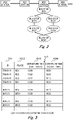
- FIG. 2 is a route map diagram used in the description of the at least one embodiment.
- the route map diagram of FIG. 2 includes a railroad line starting from a station RS1 and running through a station RS2, a station RS3, and a station RS4. There are also two bus lines from a bus stop BS3, which is closest to the station RS3, to a bus stop BS35, with one bus line running through a bus stop BS31 and a bus stop BS32, and another bus line running through a bus stop BS33 and a bus stop BS34. A person who plans to travel from the bus stop BS3 to the bus stop BS35 can thus use whichever of the two routes described above. Transfer from a train to a bus and transfer from a bus to a train are possible between the station RS3 and the bus stop BS3.
- FIG. 3 is a diagram for illustrating a configuration example of the operation diagram information 151.
- the operation diagram information 151 is information created by a railroad business operator on train operation times and information created by a public bus business operator on bus operation times.
- a record of the operation diagram information 151 includes an operation ID 1511, a place 1512, a departure time (scheduled) 1513, and a departure time (actual time) 1514, and is created for each train, for each bus, and for each stop.
- the operation ID 1511 is unique identification information of a train or a bus.
- the place 1512 is identification information of a place (a station or a bus stop) from which the train or the bus departs.
- the departure time (scheduled) 1513 is a scheduled departure time (scheduled operation diagram) of the train or the bus
- the departure time (actual time) 1514 is an actual departure time (actual operation diagram) of the train or the bus.
- the operation diagram information 151 is acquired from the railroad traffic control system 2 and the bus traffic control system 3.
- FIG. 4 is a diagram for illustrating a configuration example of the travel demands information 152.
- a record of the travel demands information 152 includes a start point 1521, an end point 1522, a start point time 1523, a route 1524, and a passenger count 1525, and is a record created for each combination of a start point and an end point about history of passengers' travel by train or by bus.
- the start point 1521 is identification information of a station or a bus stop that is a start point of travel
- the end point 1522 is identification information of a station or a bus stop that is an end point of the travel.
- the start point time 1523 is a time at which departure from the start point has taken place.
- the travel demands information 152 travel via a train ride or a bus ride is recorded, and the start point time is accordingly a departure time of the train or the bus used for the travel.
- the route 1524 is identification information of stations and bus stops through which the passengers have traveled between the start point 1521 and the end point 1522.
- the travel demands information 152 can be generated from records collected by the ticketing system 4 about boarding/disembarking of passengers.
- FIG. 5 is a diagram for illustrating a configuration example of the business operator model 153.
- the business operator model 153 is a model indicating a possibility at which delaying of a departure time of a train or a bus is accepted by a railroad business operator of the train or a public bus business operator of the bus because of an increased number of passengers.
- the business operator model 153 uses a departure time delaying time and an increase in passenger count as explanatory variables, and an acceptance possibility as an objective variable, and is a model designed so that, as shown in the graph, the acceptance possibility drops when the departure time delaying time increases, and rises when the increase in passenger count becomes larger.
- FIG. 6 is a diagram for illustrating a configuration example of the recommendation response result 154.
- a record of the recommendation response result 154 includes a target 1541, a place 1542, a departure time (scheduled) 1543, a departure time (proposed) 1544, a passenger count (normal) 1545, a passenger count (proposed) 1546, and a response result 1547, and is created for each proposal from the operation coordination system 1 to a railroad business operator or a bus business operator.
- the target 1541 is identification information of a train or a bus for which a departure time has been changed by the proposal.
- the place 1542 is identification information of a station or a bus stop at which the departure time has been changed by the proposal.
- the departure time (scheduled) 1543 is a scheduled departure time prior to a change by the proposal.
- the departure time (proposed) 1544 is a departure time after the change by the proposal.
- the passenger count (normal) 1545 is a predicted value of the number of passengers on the train or the bus prior to the change of the departure time by the proposal.
- the passenger count (proposed) 1546 is a predicted value of the number of passengers on the train or the bus after the change of the departure time by the proposal.
- the response result 1547 is information indicating whether the proposal has been accepted by the railroad business operator or the public bus business operator.
- the recommendation response result 154 shown in the table indicates that a public bus business operator has accepted a proposal of delaying a departure time of a bus 21 at the bus stop BS3 by 5 minutes and consequently increasing the number of passengers by 7 people.
- FIG. 7 is a flow chart of processing executed by the business operator model generation program 155.
- the processor 11 groups pieces of data recorded in the recommendation response result 154 by station or bus stop, and by time slot (Step 101).
- the processor 11 uses the grouped pieces of data of the recommendation response result 154 to create the business operator model 153 for each group (Step 102).
- the business operator model 153 may be generated by, for example, learning a neural network with the use of teacher data in which the departure time delaying time and the increase in passenger count are explanatory variables and a quotient of the number of accepted proposals divided by the number of proposals is an objective variable.
- the business operator model 153 may be generated also with the use of a linear regression model (logistic regression model or the like), a non-linear model (a random forest, a gradient boosting decision tree, or the like), or others, with the departure time delaying time and the increase in passenger count as explanatory variables and a quotient of the number of accepted proposals divided by the number of proposals as an objective variable.
- a linear regression model logistic regression model or the like
- a non-linear model a random forest, a gradient boosting decision tree, or the like
- FIG. 8 is a flow chart of processing executed by the coordination recommendation generation program 156.
- the coordination recommendation generation program 156 monitors actual operation diagrams provided from the railroad traffic control system 2 and the bus traffic control system 3, and is executed when a delay equal to or more than a given threshold value is detected.
- the processor 11 first extracts a delayed train from the operation diagram information 151 (Step 111).
- Step 112 the processing steps of from Step 112 to Step 121 are executed for each delayed train.
- the processor 11 uses the operation simulator to predict a time of arrival of the delayed train at a station.
- the processor 11 next refers to the operation diagram information 151 to extract a connection bus to be connected to, based on a time difference between the train and the bus in the scheduled operation diagram (Step 113). For example, with respect to an interchange train station and a transfer bus stop, a scheduled arrival time at which the train is to arrive in a case in which the train is not delayed, and transfer times determined for the transfer places are found out and used to extract a planned connection bus departing between a time point at which the determined transfer times elapse since the scheduled arrival time and a time point at which a limit transfer time elapses since the scheduled arrival time.
- the connection bus may be extracted based on the number of past transfer passengers by referring to the travel demands information 152.
- the processor 11 next estimates the number of people traveling when the planned connection bus does not wait for the train to connect (Step 114). For example, the number of passengers expected to ride the planned connection bus is estimated by the human flow simulator with the use of the scheduled operation diagram of the operation diagram information 151 and the travel demands information 152.
- the processor 11 next creates a plurality of connection waiting time plans for the planned connection bus (Step 115).
- the plurality of connection waiting time plans are created, for example, at intervals of 1 minute or other intervals from a 1-minute-long wait to a 5-minute-long wait. In other words, the number of connection waiting time plans to be created is determined by the time interval and the maximum waiting time.
- the plurality of connection waiting time plans are created for each planned connection bus.
- Step 116 the processor 11 estimates the number of traveling people for each connection waiting time plan (Step 116). For example, the number of people expected to ride the planned connection bus which has waited for the train to connect is estimated by, as in Step 114, the human flow simulator with the use of the connection waiting time plan and the travel demands information 152. When there are a plurality of routes to the destination, the number of people expected to ride is estimated for each connection waiting time plan with respect to each route.
- the number of people expected to ride is estimated for each of two routes, which are a route running through the bus stop BS31 and the bus stop BS32, and a route running through the bus stop BS33 and the bus stop BS34.
- the processor 11 next uses the business operator model 153 to calculate a probability at which this connection waiting time plan is accepted by the public bus operator (Step 117).
- the processor 11 calculates an expectation value for each connection waiting time plan, and selects a connection waiting time plan that has the largest calculated expectation value (Step 118). For example, a value obtained by multiplying the probability of acceptance by an amount of increase in the number of people expected to ride is calculated as the expectation value.
- a value obtained by multiplying the probability of acceptance by an amount of increase in the number of people expected to ride is calculated for each route, and a sum of the calculated values of all routes is obtained as the expectation value.
- the expectation value of the selected connection waiting time plan is compared to a given threshold value (Step 119).
- the calculated expectation value is less than the given threshold value, the possibility of the public bus business operator accepting the plan is small, and the process accordingly proceeds to processing of the next delayed train within the loop for delayed trains, without proposing the plan to the public bus business operator.
- the public bus business operator accepting the proposal is a possibility, and the proposal of delaying the departure time is transmitted to the bus traffic control system 3 (Step 120).
- the public bus business operator operates the bus traffic control system 3 to view the proposal (a recommendation screen 900 illustrated in FIG. 9 ) transmitted from the operation coordination system 1, determines whether to accept the proposal, and inputs whether the proposal is accepted.
- the bus traffic control system 3 transmits the input acceptance/rejection to the operation coordination system 1.
- the operation coordination system 1 stores the acceptance/rejection transmitted from the bus traffic control system 3 in the recommendation response result 154 (Step 121).
- the description given above is about a mode in which the coordination recommendation generation program 156 is executed when a train or a bus is delayed.
- the coordination recommendation generation program 156 may be used to obtain information for creating a new operation diagram and verifying convenience of transfer between transportations.
- FIG. 9 is a diagram for illustrating an example of the recommendation screen 900 to be displayed in the bus traffic control system 3.
- FIG. 9 is an illustration of an example of the recommendation screen to be displayed in the bus traffic control system 3, a proposal about delaying a train departure time is similarly displayed in the railroad traffic control system 2 as well.
- the recommendation screen 900 may also be displayed on a terminal coupled to the operation coordination system 1, separately from the bus traffic control system 3 and the railroad traffic control system 2.
- the recommendation screen 900 illustrated in FIG. 9 includes a proposal display area 901 in which contents of a proposal are displayed in numerical values, a passenger count area 902 in which an illustration of how the passenger count changes depending on the departure time delaying time is displayed, and buttons 903 and 904 to be used by the public bus business operator to input a result.
- Data displayed in the proposal display area 901 includes identification information of a bus that is a target of delaying of a departure time, identification information of a place at which the departure time is to be delayed, a departure time (scheduled), a departure time (proposed), a passenger count (normal), and a passenger count (proposed).
- passengers increase by 7 people when the departure time of the bus 21 at the bus stop BS3 is delayed by 5 minutes.
- the passenger count area 902 displays a change in passenger count for each departure time delaying time in a graph format. It is recommended to design the screen so that an act of selecting a departure time delaying time in the passenger count area 902 causes a change of data displayed in the proposal display area 901. It is understood from the passenger count area 902 that the passenger count increases when the departure time delaying time increases. A delay time that is an increased departure time delaying time but causes only a small change in passenger count can be found out from the passenger count area 902.
- a traffic control manager of the public bus business operator operates the "accept recommendation” button 903 when the public bus business operator accepts the proposal displayed on the recommendation screen 900, and operates the "reject recommendation” button 904 when the public bus business operator does not accept the proposal.
- the "accept recommendation” button 903 may be provided alone. In this case, the operation of rejecting a recommendation is omitted and, when the operation of accepting a recommendation is not performed within a given time, the bus traffic control system 3 automatically rejects the proposal, and notifies the rejection of the proposal to the operation coordination system 1.
- the "reject recommendation” button 904 may be provided alone. In this case, the operation of accepting a recommendation is omitted and, when the operation of rejecting a recommendation is not performed within a given time, the bus traffic control system 3 automatically accepts the proposal, and updates the operation diagram.
- FIG. 10 is a diagram for illustrating an example of a passenger guidance screen 1000.
- the operation diagram of the bus traffic control system 3 is updated, and a change to the operation diagram is notified to a driver.
- the bus traffic control system 3 also transmits information about the delay of the departure time to the passenger guidance system 5.
- the passenger guidance system 5 displays the information about the delay of the departure time on the guidance displays at bus stops.
- the passenger guidance screen 1000 illustrated in FIG. 10 displays identification information of the bus that is a target of delaying of the departure time, the departure time before being delayed, the delayed departure time, and a reason for delaying the departure time.
- the passenger guidance system 5 may display the information illustrated in FIG. 10 on terminals of passengers.
- a plan highly likely to be accepted by a transportation business operator can be proposed, and smooth transfer can be provided to passengers.
- the transportation business operator can therefore efficiently transport passengers and reduce operation in which few passengers are transported. For passengers, convenience is improved by smooth transfer between transportations, and quick arrival at a destination is achieved.
- the smooth transfer also prevents passengers from being stranded, to thereby ease overcrowding at a station.
- the information of programs, tables, and files to implement the functions may be stored in a storage device such as a memory, a hard disk drive, or an SSD (a Solid State Drive), or a storage medium such as an IC card, or an SD card.
- a storage device such as a memory, a hard disk drive, or an SSD (a Solid State Drive), or a storage medium such as an IC card, or an SD card.
Landscapes
- Engineering & Computer Science (AREA)
- Business, Economics & Management (AREA)
- Human Resources & Organizations (AREA)
- Economics (AREA)
- Strategic Management (AREA)
- Theoretical Computer Science (AREA)
- Tourism & Hospitality (AREA)
- General Physics & Mathematics (AREA)
- Marketing (AREA)
- General Business, Economics & Management (AREA)
- Physics & Mathematics (AREA)
- Quality & Reliability (AREA)
- Game Theory and Decision Science (AREA)
- Operations Research (AREA)
- Entrepreneurship & Innovation (AREA)
- Development Economics (AREA)
- Mechanical Engineering (AREA)
- Health & Medical Sciences (AREA)
- General Health & Medical Sciences (AREA)
- Primary Health Care (AREA)
- Management, Administration, Business Operations System, And Electronic Commerce (AREA)
- Train Traffic Observation, Control, And Security (AREA)
Abstract
Description
- This invention relates to a coordination system for promoting coordination among transportations.
- Coordination among a plurality of transportations, such as railroads and buses, is demanded. For example, when departure of a bus that is a connection from a delayed train is delayed, convenience of passengers who plan to transfer to the bus is improved, and overcrowding with stranded passengers at a train station can be eased.
- The background art in this technical field includes the following related art. In
JP 2012-111375 A - The background art described above is about smooth determination of a train operation diagram regarding connection of a last train. However, overcrowding with stranded passengers at a station is required to be eased at times other than around the time of last trains as well, and adjustment among a plurality of transportations is required. It is also required to propose a plan which is easy for a business operator of transportation that is a connection from transportation run by another entity to adopt. In the background art described above, however, a possibility of a proposal of being adopted by the business operator is not considered.
- An object of this invention is to achieve a coordination system for proposing a plan which is easy for a business operator of transportation that is a connection from transportation run by another entity to adopt.
- The representative one of inventions disclosed in this application is outlined as follows. There is provided a coordination system for creating a proposal that promotes coordination among a plurality of transportations, the coordination system comprising: an arithmetic device (11) configured to execute given processing; and a storage device (15) accessible to the arithmetic device, the storage device being configured to store, for every one of proposals proposing to delay departure of one of the plurality of transportations, a delaying time of the one of the proposals, an amount of increase in passenger count brought about by delaying the departure in accordance with the one of the proposals, and information on whether the one of the proposals has been accepted, in association with one another, the arithmetic device being configured to: group the proposals by operation and by stop into groups; and generate, for each of the groups, a model in which delaying times of the proposals proposing to delay departure of some of the plurality of transportations and amounts of increase in passenger count brought about by delaying the departure in accordance with the proposals are explanatory variables, and probabilities of acceptance of the proposals are objective variables.
- According to the at least one aspect of this invention, a transport efficiency can be improved. Problems, configurations, and effects other than those described above are made clear based on the following description of at least one embodiment of this invention.
-
-
FIG. 1 is a block diagram for illustrating a configuration of the operation coordination system according to the at least one embodiment of this invention. -
FIG. 2 is a route map diagram used in the description of the at least one embodiment. -
FIG. 3 is a diagram for illustrating a configuration example of the operation diagram information. -
FIG. 4 is a diagram for illustrating a configuration example of the travel demands information. -
FIG. 5 is a diagram for illustrating a configuration example of the business operator model. -
FIG. 6 is a diagram for illustrating a configuration example of the recommendation response result. -
FIG. 7 is a flow chart of processing executed by the business operator model generation program. -
FIG. 8 is a flow chart of processing executed by the coordination recommendation generation program. -
FIG. 9 is a diagram for illustrating an example of therecommendation screen 900 to be displayed in the bus traffic control system. -
FIG. 10 is a diagram for illustrating an example of a passenger guidance screen. - An outline of an
operation coordination system 1 according to at least one embodiment of this invention is described first. Abusiness operator model 153 is created with the use of response results of a transportation business operator in response to past proposals. Transportation that is a connection is then extracted, and a connection waiting time plan suggesting an amount of time by which a departure time of the transportation that is a connection is to be delayed is created. Thebusiness operator model 153 is then referred to, to thereby calculate an expectation value of the created connection waiting time plan. A plan highly likely to be accepted by the transportation business operator is thus proposed. -
FIG. 1 is a block diagram for illustrating a configuration of theoperation coordination system 1 according to the at least one embodiment of this invention. - The
operation coordination system 1 according to the at least one embodiment is configured from a computer including a processor (CPU) 11, amemory 12, an input/output unit 13, acommunication unit 14, and astorage unit 15. - The
processor 11 is an arithmetic device for executing programs stored in thememory 12. Theprocessor 11 executes various programs (a business operatormodel generation program 155, a coordinationrecommendation generation program 156, and others), to thereby implement function modules of theoperation coordination system 1. Part of processing carried out by theprocessor 11 by executing programs may be executed by another arithmetic device (for example, an ASIC, an FPGA, or a similar piece of hardware). - The
memory 12 includes a ROM, which is a non-volatile storage element, and a RAM, which is a volatile storage element. The ROM stores an unchanging program (for example, BIOS) among others. The RAM is a dynamic random access memory (DRAM) or a similar high-speed and volatile storage element, and temporality stores a program executed by theprocessor 11 and data used when the program is executed. - The input/
output unit 13 is an interface through which input from an operator is received by way of a keyboard, a mouse, or another input device coupled to the input/output unit 13, and through which a result of executing a program is output, by way of a display device, a printer, or another output device coupled to the input/output unit 13, in a format visibly recognizable to the operator. The input/output unit 13 may include an interface (for example, a USB) through which data is transmitted and received in accordance with a given protocol. An input/output unit may be provided by a user terminal coupled to theoperation coordination system 1 via a network. In this case, theoperation coordination system 1 may have functions of a Web server, and theoperation coordination system 1 may be accessed by a Web browser of the user terminal in accordance with a given protocol (for example, http). - The
communication unit 14 is a network interface device for controlling communication to and from other system (for example, a railroadtraffic control system 2, a bustraffic control system 3, aticketing system 4, and a passenger guidance system 5) in accordance with a given protocol. - The
storage unit 15 is a large-capacity and non-volatile storage device, such as a magnetic storage device (an HDD) or a flash memory (an SSD). Thestorage unit 15 stores data (for example,operation diagram information 151,travel demands information 152, thebusiness operator model 153, and a recommendation response result 154) used by theprocessor 11 when theprocessor 11 executes programs, and the programs (for example, the coordinationrecommendation generation program 156 and the business operator model generation program 155) executed by theprocessor 11. In other words, the programs are read out of thestorage unit 15, loaded onto thememory 12, and executed by theprocessor 11, to thereby implement functions of theoperation coordination system 1. - The programs to be executed by the
processor 11 are provided to theoperation coordination system 1 via a removable medium (such as a CD-ROM or a flash memory) or the network, and are stored in a non-volatile and non-transitory storage medium of thestorage unit 15. Therefore, theoperation coordination system 1 may include an interface which reads out data from a removable medium. - The
operation coordination system 1 is a computer system constructed from physically one computer or from a plurality of computers constructed logically or physically, or may operate on a virtual machine constructed from a plurality of physical computer resources. For example, the coordinationrecommendation generation program 156 and the business operatormodel generation program 155 may operate on a physical or logical computer separately provided for each thereof, or a plurality of programs of those may be combined to operate on one physical or logical computer. Theoperation diagram information 151 is information created by a railroad business operator on train operation times and information created by a public bus business operator on bus operation times, and details thereof are described later with reference toFIG. 3 . Thetravel demands information 152 is information on history of travel of passengers by a train or a bus, and details thereof are described later with reference toFIG. 4 . Thebusiness operator model 153 is a model indicating a possibility at which delaying of a departure time of a train or a bus is accepted by a railroad business operator of the train or a public bus business operator of the bus, and details thereof are described later with reference toFIG. 5 . Therecommendation response result 154 is information on contents of a proposal by theoperation coordination system 1 and contents of a response from a railroad business operator or a bus business operator, and details thereof are described later with reference toFIG. 6 . - The business operator
model generation program 155 is a program for creating thebusiness operator model 153 with the use of therecommendation response result 154, and details thereof are described later with reference toFIG. 7 . The coordinationrecommendation generation program 156 is a program for creating a proposal about an amount of time by which a departure time is to be delayed to a railroad business operator or a public bus business operator, and includes an operation simulator for predicting an operation diagram of a train or a bus and a human flow simulator for predicting the number of passengers of a train or a bus. Details of the coordinationrecommendation generation program 156 are described later with reference toFIG. 8 . - The railroad
traffic control system 2 is a computer system to be used by a railroad business operator to control railroad traffic. The bustraffic control system 3 is a computer system to be used by a public bus business operator to control public bus traffic. Theticketing system 4 is a computer system with which a railroad business operator or a public bus business operator manages payment of fares by passengers, and collects, for example, entrance/exit data of an entrance gate machine and boarding/disembarking data of a fare box. Thepassenger guidance system 5 is a computer system for guiding passengers at a railroad station or a bus stop, and displays, for example, operation information acquired from the railroadtraffic control system 2 or the bustraffic control system 3 on a destination guidance display installed at a station, a guidance display at a bus stop, or a terminal of a passenger. -
FIG. 2 is a route map diagram used in the description of the at least one embodiment. - The route map diagram of
FIG. 2 includes a railroad line starting from a station RS1 and running through a station RS2, a station RS3, and a station RS4. There are also two bus lines from a bus stop BS3, which is closest to the station RS3, to a bus stop BS35, with one bus line running through a bus stop BS31 and a bus stop BS32, and another bus line running through a bus stop BS33 and a bus stop BS34. A person who plans to travel from the bus stop BS3 to the bus stop BS35 can thus use whichever of the two routes described above. Transfer from a train to a bus and transfer from a bus to a train are possible between the station RS3 and the bus stop BS3. -
FIG. 3 is a diagram for illustrating a configuration example of theoperation diagram information 151. - The
operation diagram information 151 is information created by a railroad business operator on train operation times and information created by a public bus business operator on bus operation times. A record of theoperation diagram information 151 includes anoperation ID 1511, aplace 1512, a departure time (scheduled) 1513, and a departure time (actual time) 1514, and is created for each train, for each bus, and for each stop. Theoperation ID 1511 is unique identification information of a train or a bus. Theplace 1512 is identification information of a place (a station or a bus stop) from which the train or the bus departs. The departure time (scheduled) 1513 is a scheduled departure time (scheduled operation diagram) of the train or the bus, and the departure time (actual time) 1514 is an actual departure time (actual operation diagram) of the train or the bus. Theoperation diagram information 151 is acquired from the railroadtraffic control system 2 and the bustraffic control system 3. -
FIG. 4 is a diagram for illustrating a configuration example of the travel demandsinformation 152. - A record of the travel demands
information 152 includes astart point 1521, anend point 1522, astart point time 1523, aroute 1524, and apassenger count 1525, and is a record created for each combination of a start point and an end point about history of passengers' travel by train or by bus. Thestart point 1521 is identification information of a station or a bus stop that is a start point of travel, and theend point 1522 is identification information of a station or a bus stop that is an end point of the travel. Thestart point time 1523 is a time at which departure from the start point has taken place. In the travel demandsinformation 152, travel via a train ride or a bus ride is recorded, and the start point time is accordingly a departure time of the train or the bus used for the travel. Theroute 1524 is identification information of stations and bus stops through which the passengers have traveled between thestart point 1521 and theend point 1522. The travel demandsinformation 152 can be generated from records collected by theticketing system 4 about boarding/disembarking of passengers. -
FIG. 5 is a diagram for illustrating a configuration example of thebusiness operator model 153. - The
business operator model 153 is a model indicating a possibility at which delaying of a departure time of a train or a bus is accepted by a railroad business operator of the train or a public bus business operator of the bus because of an increased number of passengers. Thebusiness operator model 153 uses a departure time delaying time and an increase in passenger count as explanatory variables, and an acceptance possibility as an objective variable, and is a model designed so that, as shown in the graph, the acceptance possibility drops when the departure time delaying time increases, and rises when the increase in passenger count becomes larger. -
FIG. 6 is a diagram for illustrating a configuration example of therecommendation response result 154. - A record of the
recommendation response result 154 includes atarget 1541, aplace 1542, a departure time (scheduled) 1543, a departure time (proposed) 1544, a passenger count (normal) 1545, a passenger count (proposed) 1546, and aresponse result 1547, and is created for each proposal from theoperation coordination system 1 to a railroad business operator or a bus business operator. Thetarget 1541 is identification information of a train or a bus for which a departure time has been changed by the proposal. Theplace 1542 is identification information of a station or a bus stop at which the departure time has been changed by the proposal. The departure time (scheduled) 1543 is a scheduled departure time prior to a change by the proposal. The departure time (proposed) 1544 is a departure time after the change by the proposal. The passenger count (normal) 1545 is a predicted value of the number of passengers on the train or the bus prior to the change of the departure time by the proposal. The passenger count (proposed) 1546 is a predicted value of the number of passengers on the train or the bus after the change of the departure time by the proposal. Theresponse result 1547 is information indicating whether the proposal has been accepted by the railroad business operator or the public bus business operator. - The
recommendation response result 154 shown in the table indicates that a public bus business operator has accepted a proposal of delaying a departure time of a bus 21 at the bus stop BS3 by 5 minutes and consequently increasing the number of passengers by 7 people. -
FIG. 7 is a flow chart of processing executed by the business operatormodel generation program 155. - The
processor 11 groups pieces of data recorded in therecommendation response result 154 by station or bus stop, and by time slot (Step 101). - The
processor 11 then uses the grouped pieces of data of therecommendation response result 154 to create thebusiness operator model 153 for each group (Step 102). Thebusiness operator model 153 may be generated by, for example, learning a neural network with the use of teacher data in which the departure time delaying time and the increase in passenger count are explanatory variables and a quotient of the number of accepted proposals divided by the number of proposals is an objective variable. Thebusiness operator model 153 may be generated also with the use of a linear regression model (logistic regression model or the like), a non-linear model (a random forest, a gradient boosting decision tree, or the like), or others, with the departure time delaying time and the increase in passenger count as explanatory variables and a quotient of the number of accepted proposals divided by the number of proposals as an objective variable. -
FIG. 8 is a flow chart of processing executed by the coordinationrecommendation generation program 156. InFIG. 8 , a case of transfer from a train to a bus is described, but the processing is also applicable to transfer from a train to another train, transfer from a bus to another bus, and transfer from a bus to a train. The coordinationrecommendation generation program 156 monitors actual operation diagrams provided from the railroadtraffic control system 2 and the bustraffic control system 3, and is executed when a delay equal to or more than a given threshold value is detected. - The
processor 11 first extracts a delayed train from the operation diagram information 151 (Step 111). - Subsequently, the processing steps of from
Step 112 to Step 121 are executed for each delayed train. InStep 112, theprocessor 11 uses the operation simulator to predict a time of arrival of the delayed train at a station. - The
processor 11 next refers to theoperation diagram information 151 to extract a connection bus to be connected to, based on a time difference between the train and the bus in the scheduled operation diagram (Step 113). For example, with respect to an interchange train station and a transfer bus stop, a scheduled arrival time at which the train is to arrive in a case in which the train is not delayed, and transfer times determined for the transfer places are found out and used to extract a planned connection bus departing between a time point at which the determined transfer times elapse since the scheduled arrival time and a time point at which a limit transfer time elapses since the scheduled arrival time. The connection bus may be extracted based on the number of past transfer passengers by referring to the travel demandsinformation 152. - The
processor 11 next estimates the number of people traveling when the planned connection bus does not wait for the train to connect (Step 114). For example, the number of passengers expected to ride the planned connection bus is estimated by the human flow simulator with the use of the scheduled operation diagram of theoperation diagram information 151 and the travel demandsinformation 152. - The
processor 11 next creates a plurality of connection waiting time plans for the planned connection bus (Step 115). The plurality of connection waiting time plans are created, for example, at intervals of 1 minute or other intervals from a 1-minute-long wait to a 5-minute-long wait. In other words, the number of connection waiting time plans to be created is determined by the time interval and the maximum waiting time. When there are a plurality of planned connection buses, the plurality of connection waiting time plans are created for each planned connection bus. - The processing steps of
Step 116 andStep 117 are then executed for each connection waiting time plan. InStep 116, theprocessor 11 estimates the number of traveling people for each connection waiting time plan (Step 116). For example, the number of people expected to ride the planned connection bus which has waited for the train to connect is estimated by, as inStep 114, the human flow simulator with the use of the connection waiting time plan and the travel demandsinformation 152. When there are a plurality of routes to the destination, the number of people expected to ride is estimated for each connection waiting time plan with respect to each route. For example, in a case of travel from the bus stop BS3 to the bus stop BS35, the number of people expected to ride is estimated for each of two routes, which are a route running through the bus stop BS31 and the bus stop BS32, and a route running through the bus stop BS33 and the bus stop BS34. - The
processor 11 next uses thebusiness operator model 153 to calculate a probability at which this connection waiting time plan is accepted by the public bus operator (Step 117). - After the calculation of the probability of acceptance is finished for every connection waiting time plan, the
processor 11 calculates an expectation value for each connection waiting time plan, and selects a connection waiting time plan that has the largest calculated expectation value (Step 118). For example, a value obtained by multiplying the probability of acceptance by an amount of increase in the number of people expected to ride is calculated as the expectation value. When there are a plurality of routes to the destination, a value obtained by multiplying the probability of acceptance by an amount of increase in the number of people expected to ride is calculated for each route, and a sum of the calculated values of all routes is obtained as the expectation value. - Next, the expectation value of the selected connection waiting time plan is compared to a given threshold value (Step 119). When the calculated expectation value is less than the given threshold value, the possibility of the public bus business operator accepting the plan is small, and the process accordingly proceeds to processing of the next delayed train within the loop for delayed trains, without proposing the plan to the public bus business operator. When the calculated expectation value is equal to or more than the given threshold value, on the other hand, the public bus business operator accepting the proposal is a possibility, and the proposal of delaying the departure time is transmitted to the bus traffic control system 3 (Step 120).
- The public bus business operator operates the bus
traffic control system 3 to view the proposal (arecommendation screen 900 illustrated inFIG. 9 ) transmitted from theoperation coordination system 1, determines whether to accept the proposal, and inputs whether the proposal is accepted. The bustraffic control system 3 transmits the input acceptance/rejection to theoperation coordination system 1. Theoperation coordination system 1 stores the acceptance/rejection transmitted from the bustraffic control system 3 in the recommendation response result 154 (Step 121). - The description given above is about a mode in which the coordination
recommendation generation program 156 is executed when a train or a bus is delayed. The coordinationrecommendation generation program 156, however, may be used to obtain information for creating a new operation diagram and verifying convenience of transfer between transportations. -
FIG. 9 is a diagram for illustrating an example of therecommendation screen 900 to be displayed in the bustraffic control system 3. AlthoughFIG. 9 is an illustration of an example of the recommendation screen to be displayed in the bustraffic control system 3, a proposal about delaying a train departure time is similarly displayed in the railroadtraffic control system 2 as well. Therecommendation screen 900 may also be displayed on a terminal coupled to theoperation coordination system 1, separately from the bustraffic control system 3 and the railroadtraffic control system 2. - The
recommendation screen 900 illustrated inFIG. 9 includes aproposal display area 901 in which contents of a proposal are displayed in numerical values, apassenger count area 902 in which an illustration of how the passenger count changes depending on the departure time delaying time is displayed, andbuttons - Data displayed in the
proposal display area 901 includes identification information of a bus that is a target of delaying of a departure time, identification information of a place at which the departure time is to be delayed, a departure time (scheduled), a departure time (proposed), a passenger count (normal), and a passenger count (proposed). In the illustrated proposal, passengers increase by 7 people when the departure time of the bus 21 at the bus stop BS3 is delayed by 5 minutes. - The
passenger count area 902 displays a change in passenger count for each departure time delaying time in a graph format. It is recommended to design the screen so that an act of selecting a departure time delaying time in thepassenger count area 902 causes a change of data displayed in theproposal display area 901. It is understood from thepassenger count area 902 that the passenger count increases when the departure time delaying time increases. A delay time that is an increased departure time delaying time but causes only a small change in passenger count can be found out from thepassenger count area 902. - A traffic control manager of the public bus business operator operates the "accept recommendation"
button 903 when the public bus business operator accepts the proposal displayed on therecommendation screen 900, and operates the "reject recommendation"button 904 when the public bus business operator does not accept the proposal. The "accept recommendation"button 903 may be provided alone. In this case, the operation of rejecting a recommendation is omitted and, when the operation of accepting a recommendation is not performed within a given time, the bustraffic control system 3 automatically rejects the proposal, and notifies the rejection of the proposal to theoperation coordination system 1. The "reject recommendation"button 904 may be provided alone. In this case, the operation of accepting a recommendation is omitted and, when the operation of rejecting a recommendation is not performed within a given time, the bustraffic control system 3 automatically accepts the proposal, and updates the operation diagram. -
FIG. 10 is a diagram for illustrating an example of apassenger guidance screen 1000. - When the traffic control manager of the public bus business operator operates the "accept recommendation"
button 903 of therecommendation screen 900, the operation diagram of the bustraffic control system 3 is updated, and a change to the operation diagram is notified to a driver. The bustraffic control system 3 also transmits information about the delay of the departure time to thepassenger guidance system 5. Thepassenger guidance system 5 displays the information about the delay of the departure time on the guidance displays at bus stops. For example, thepassenger guidance screen 1000 illustrated inFIG. 10 displays identification information of the bus that is a target of delaying of the departure time, the departure time before being delayed, the delayed departure time, and a reason for delaying the departure time. Thepassenger guidance system 5 may display the information illustrated inFIG. 10 on terminals of passengers. - As described above, according to the
operation coordination system 1 of the at least one embodiment, a plan highly likely to be accepted by a transportation business operator can be proposed, and smooth transfer can be provided to passengers. The transportation business operator can therefore efficiently transport passengers and reduce operation in which few passengers are transported. For passengers, convenience is improved by smooth transfer between transportations, and quick arrival at a destination is achieved. The smooth transfer also prevents passengers from being stranded, to thereby ease overcrowding at a station. - This invention is not limited to the above-described embodiments but includes various modifications. The above-described embodiments are explained in details for better understanding of this invention and are not limited to those including all the configurations described above. A part of the configuration of one embodiment may be replaced with that of another embodiment; the configuration of one embodiment may be incorporated to the configuration of another embodiment. A part of the configuration of each embodiment may be added, deleted, or replaced by that of a different configuration.
- The above-described configurations, functions, processing modules, and processing means, for all or a part of them, may be implemented by hardware: for example, by designing an integrated circuit, and may be implemented by software, which means that a processor interprets and executes programs providing the functions.
- The information of programs, tables, and files to implement the functions may be stored in a storage device such as a memory, a hard disk drive, or an SSD (a Solid State Drive), or a storage medium such as an IC card, or an SD card.
- The drawings illustrate control lines and information lines as considered necessary for explanation but do not illustrate all control lines or information lines in the products. It can be considered that almost of all components are actually interconnected.
Claims (10)
- A coordination system for creating a proposal that promotes coordination among a plurality of transportations, the coordination system comprising:an arithmetic device (11) configured to execute given processing; anda storage device (15) accessible to the arithmetic device,the storage device being configured to store, for every one of proposals proposing to delay departure of one of the plurality of transportations, a delaying time of the one of the proposals, an amount of increase in passenger count brought about by delaying the departure in accordance with the one of the proposals, and information on whether the one of the proposals has been accepted, in association with one another,the arithmetic device being configured to:group the proposals by operation and by stop into groups; andgenerate, for each of the groups, a model in which delaying times of the proposals proposing to delay departure of some of the plurality of transportations and amounts of increase in passenger count brought about by delaying the departure in accordance with the proposals are explanatory variables, and probabilities of acceptance of the proposals are objective variables.
- The coordination system according to claim 1, wherein the arithmetic device is configured to:create a plurality of connection waiting time plans for connection from first transportation to second transportation;estimate, for every one of the plurality of created connection waiting time plans, a passenger count of the second transportation; andcalculate, with use of the model, a probability at which the one of the plurality of connection waiting time plans is accepted.
- The coordination system according to claim 2, wherein the arithmetic device is configured to:predict a time at which a delayed operation of the first transportation arrives at a stop;extract, based on a time difference between a scheduled operation diagram of the first transportation and a scheduled operation diagram of the second transportation, an operation of the second transportation to connect to; andestimate a passenger count for a case in which the extracted operation of the second transportation does not wait for the delayed operation of the first transportation to connect.
- The coordination system according to claim 2, wherein the arithmetic device is configured to:calculate, for every one of the plurality of connection waiting time plans, an expectation value by multiplying a probability at which the one of the proposals is accepted by an amount of increase in passenger count of the second transportation;select one of the plurality of connection waiting time plans that has the largest calculated expectation value; andtransmit a proposal of the selected one of the plurality of connection waiting time plans to a traffic control system.
- The coordination system according to claim 4, wherein the arithmetic device is configured to calculate, in a case where a plurality of routes for the second transportation exist, an expectation value by performing, for each of the plurality of routes, multiplication in which the probability of acceptance of the one of the proposals is multiplied by the amount of increase in passenger count of the second transportation, and summing up values obtained through the multiplication for all of the plurality of routes.
- A coordination support method for creating a proposal that promotes coordination among a plurality of transportations by a coordination system,the coordination system including: an arithmetic device configured to execute given processing; and a storage device accessible to the arithmetic device,the storage device being configured to store, for every one of proposals proposing to delay departure of one of the plurality of transportations, a delaying time of the one of the proposals, an amount of increase in passenger count brought about by delaying the departure in accordance with the one of the proposals, and information on whether the one of the proposals has been accepted, in association with one another,the coordination support method comprising the steps of:grouping, by the arithmetic device, the proposals by operation and by stop into groups; andgenerating, by the arithmetic device, for each of the groups, a model in which delaying times of the proposals proposing to delay departure of some of the plurality of transportations and amounts of increase in passenger count brought about by delaying the departure in accordance with the proposals are explanatory variables, and probabilities of acceptance of the proposals are objective variables.
- The coordination support method according to claim 6, further comprising the steps of:creating, by the arithmetic device, a plurality of connection waiting time plans for connection from first transportation to second transportation;estimating, by the arithmetic device, for every one of the plurality of created connection waiting time plans, a passenger count of the second transportation; andcalculating, by the arithmetic device, with use of the model, a probability at which the one of the plurality of connection waiting time plans is accepted.
- The coordination support method according to claim 7, further comprising the steps of:predicting, by the arithmetic device, a time at which a delayed operation of the first transportation arrives at a stop;extracting, by the arithmetic device, based on a time difference between a scheduled operation diagram of the first transportation and a scheduled operation diagram of the second transportation, an operation of the second transportation to connect to; andestimating, by the arithmetic device, a passenger count for a case in which the extracted operation of the second transportation does not wait for the delayed operation of the first transportation to connect.
- The coordination support method according to claim 7, further comprising the steps of:calculating, by the arithmetic device, for every one of the plurality of connection waiting time plans, an expectation value by multiplying a probability at which the one of the proposals is accepted by an amount of increase in passenger count of the second transportation;selecting, by the arithmetic device, one of the plurality of connection waiting time plans that has the largest calculated expectation value; andtransmitting, by the arithmetic device, a proposal of the selected one of the plurality of connection waiting time plans to a traffic control system.
- The coordination support method according to claim 9, further comprising the step of calculating, by the arithmetic device, when a plurality of routes for the second transportation exist, an expectation value by performing, for each of the plurality of routes, multiplication in which the probability of acceptance of the one of the proposals is multiplied by the amount of increase in passenger count of the second transportation, and summing up values obtained through the multiplication for all of the plurality of routes.
Applications Claiming Priority (1)
| Application Number | Priority Date | Filing Date | Title |
|---|---|---|---|
| JP2021075691A JP7611759B2 (en) | 2021-04-28 | 2021-04-28 | Collaboration system and collaboration support method |
Publications (2)
| Publication Number | Publication Date |
|---|---|
| EP4082870A1 true EP4082870A1 (en) | 2022-11-02 |
| EP4082870B1 EP4082870B1 (en) | 2025-07-16 |
Family
ID=81326424
Family Applications (1)
| Application Number | Title | Priority Date | Filing Date |
|---|---|---|---|
| EP22165923.8A Active EP4082870B1 (en) | 2021-04-28 | 2022-03-31 | Coordination system and coordination support method |
Country Status (2)
| Country | Link |
|---|---|
| EP (1) | EP4082870B1 (en) |
| JP (1) | JP7611759B2 (en) |
Families Citing this family (1)
| Publication number | Priority date | Publication date | Assignee | Title |
|---|---|---|---|---|
| JP7857853B2 (en) * | 2022-12-16 | 2026-05-13 | 株式会社日立製作所 | Arrival and departure estimation integration device, arrival and departure estimation integration method, and arrival and departure estimation integration system |
Citations (2)
| Publication number | Priority date | Publication date | Assignee | Title |
|---|---|---|---|---|
| JP2012111375A (en) | 2010-11-25 | 2012-06-14 | Hitachi Ltd | Device, method and program for predicting connection of last train |
| GB2508508A (en) * | 2012-11-06 | 2014-06-04 | Hitachi Ltd | Timetable replanning to restore normal running |
Family Cites Families (6)
| Publication number | Priority date | Publication date | Assignee | Title |
|---|---|---|---|---|
| JP2000090067A (en) | 1998-09-10 | 2000-03-31 | Fujitsu Ltd | Apparatus and method for finding optimal solution |
| JP2011255766A (en) | 2010-06-08 | 2011-12-22 | Toshiba Corp | Train location and transit connection information management device |
| JP6773211B2 (en) | 2017-03-14 | 2020-10-21 | 富士通株式会社 | Riding support system, riding support method and riding support program |
| WO2019146044A1 (en) | 2018-01-25 | 2019-08-01 | 日本電気株式会社 | Negotiation device, estimation method, program, and estimation device |
| CN108622142A (en) | 2018-03-30 | 2018-10-09 | 卡斯柯信号有限公司 | A kind of train intelligent operation adjustment system and method based on real-time passenger flow |
| JP6735875B1 (en) | 2019-04-15 | 2020-08-05 | 鉄道情報システム株式会社 | Reservation number prediction device |
-
2021
- 2021-04-28 JP JP2021075691A patent/JP7611759B2/en active Active
-
2022
- 2022-03-31 EP EP22165923.8A patent/EP4082870B1/en active Active
Patent Citations (2)
| Publication number | Priority date | Publication date | Assignee | Title |
|---|---|---|---|---|
| JP2012111375A (en) | 2010-11-25 | 2012-06-14 | Hitachi Ltd | Device, method and program for predicting connection of last train |
| GB2508508A (en) * | 2012-11-06 | 2014-06-04 | Hitachi Ltd | Timetable replanning to restore normal running |
Non-Patent Citations (1)
| Title |
|---|
| SPARING DANIEL ET AL: "Identifying effective guaranteed connections in a multimodal public transport network", PUBLIC TRANSPORT, SPRINGER BERLIN HEIDELBERG, BERLIN/HEIDELBERG, vol. 5, no. 1, 16 July 2013 (2013-07-16), pages 79 - 94, XP035302688, ISSN: 1866-749X, [retrieved on 20130716], DOI: 10.1007/S12469-013-0068-6 * |
Also Published As
| Publication number | Publication date |
|---|---|
| EP4082870B1 (en) | 2025-07-16 |
| JP7611759B2 (en) | 2025-01-10 |
| JP2022169944A (en) | 2022-11-10 |
Similar Documents
| Publication | Publication Date | Title |
|---|---|---|
| He et al. | Estimating the destination of unlinked trips in transit smart card fare data | |
| WO2020115986A1 (en) | Benefit distribution device, method, and non-transitory computer-readable medium | |
| JP6895325B2 (en) | Traffic demand forecasting device, traffic demand forecasting method, and traffic demand forecasting program | |
| US10621529B2 (en) | Goal-based travel reconstruction | |
| CN105303245B (en) | Traffic analysis system and traffic analysis method | |
| CN112348537B (en) | Information processing method, device, electronic equipment and storage medium | |
| US11928618B2 (en) | Transport allocation planning system, information processing apparatus, and method for controlling transport allocation planning system | |
| EP4328846A1 (en) | Operation proposal system and operation proposal producing method | |
| US10402755B2 (en) | Transportation service information providing apparatus, and transportation service information providing method | |
| JP2019091389A5 (en) | ||
| EP4082870B1 (en) | Coordination system and coordination support method | |
| JP2016078832A (en) | Demand prediction information preparation system and demand prediction system, and method for preparation of demand prediction information | |
| Graves et al. | Customer journey time metrics for New York city bus service using big data | |
| JP6649121B2 (en) | Crew operation management system and crew operation management method | |
| JP7295723B2 (en) | MAINTENANCE WORK PLANNING SUPPORT DEVICE AND MAINTENANCE WORK PLANNING SUPPORT METHOD | |
| KR102854800B1 (en) | Method for logistics intermediation platform service based on shared economy and server implementing the same | |
| JP5953922B2 (en) | Usage status calculation program, usage status calculation method, and usage status calculation device | |
| JP5929231B2 (en) | Calculation device, program, and calculation method | |
| JP7449192B2 (en) | Timetable information management system, timetable information management method, and operation guidance system | |
| KR20210113026A (en) | Method for providing service of generation and management trip plan and system for providing service of generation and management trip plan | |
| KR102948386B1 (en) | Standing passenger priority ranking server for idle seat reallocation and method performing thereof | |
| US11847592B2 (en) | Required time prediction apparatus, control method, and non-transitory storage medium | |
| JP5768704B2 (en) | Taxi user information output method, taxi user information output program, and taxi user information output device | |
| JP2023163494A (en) | Information processing method, program and information processing device | |
| WO2018161006A1 (en) | Managing uncertainty for reliable fleet assignment across aircraft fleet operators |
Legal Events
| Date | Code | Title | Description |
|---|---|---|---|
| PUAI | Public reference made under article 153(3) epc to a published international application that has entered the european phase |
Free format text: ORIGINAL CODE: 0009012 |
|
| STAA | Information on the status of an ep patent application or granted ep patent |
Free format text: STATUS: REQUEST FOR EXAMINATION WAS MADE |
|
| 17P | Request for examination filed |
Effective date: 20220331 |
|
| AK | Designated contracting states |
Kind code of ref document: A1 Designated state(s): AL AT BE BG CH CY CZ DE DK EE ES FI FR GB GR HR HU IE IS IT LI LT LU LV MC MK MT NL NO PL PT RO RS SE SI SK SM TR |
|
| GRAP | Despatch of communication of intention to grant a patent |
Free format text: ORIGINAL CODE: EPIDOSNIGR1 |
|
| STAA | Information on the status of an ep patent application or granted ep patent |
Free format text: STATUS: GRANT OF PATENT IS INTENDED |
|
| RIC1 | Information provided on ipc code assigned before grant |
Ipc: G06Q 10/04 20120101ALN20250227BHEP Ipc: G06Q 50/40 20240101ALI20250227BHEP Ipc: B61L 27/12 20220101AFI20250227BHEP |
|
| RIC1 | Information provided on ipc code assigned before grant |
Ipc: G06Q 10/04 20120101ALN20250306BHEP Ipc: G06Q 50/40 20240101ALI20250306BHEP Ipc: B61L 27/12 20220101AFI20250306BHEP |
|
| INTG | Intention to grant announced |
Effective date: 20250314 |
|
| GRAS | Grant fee paid |
Free format text: ORIGINAL CODE: EPIDOSNIGR3 |
|
| GRAA | (expected) grant |
Free format text: ORIGINAL CODE: 0009210 |
|
| STAA | Information on the status of an ep patent application or granted ep patent |
Free format text: STATUS: THE PATENT HAS BEEN GRANTED |
|
| AK | Designated contracting states |
Kind code of ref document: B1 Designated state(s): AL AT BE BG CH CY CZ DE DK EE ES FI FR GB GR HR HU IE IS IT LI LT LU LV MC MK MT NL NO PL PT RO RS SE SI SK SM TR |
|
| REG | Reference to a national code |
Ref country code: GB Ref legal event code: FG4D |
|
| REG | Reference to a national code |
Ref country code: CH Ref legal event code: EP Ref country code: DE Ref legal event code: R096 Ref document number: 602022017524 Country of ref document: DE |
|
| REG | Reference to a national code |
Ref country code: IE Ref legal event code: FG4D |
|
| REG | Reference to a national code |
Ref country code: NL Ref legal event code: MP Effective date: 20250716 |
|
| PG25 | Lapsed in a contracting state [announced via postgrant information from national office to epo] |
Ref country code: PT Free format text: LAPSE BECAUSE OF FAILURE TO SUBMIT A TRANSLATION OF THE DESCRIPTION OR TO PAY THE FEE WITHIN THE PRESCRIBED TIME-LIMIT Effective date: 20251117 |
|
| PG25 | Lapsed in a contracting state [announced via postgrant information from national office to epo] |
Ref country code: NL Free format text: LAPSE BECAUSE OF FAILURE TO SUBMIT A TRANSLATION OF THE DESCRIPTION OR TO PAY THE FEE WITHIN THE PRESCRIBED TIME-LIMIT Effective date: 20250716 |
|
| REG | Reference to a national code |
Ref country code: AT Ref legal event code: MK05 Ref document number: 1813806 Country of ref document: AT Kind code of ref document: T Effective date: 20250716 |
|
| PG25 | Lapsed in a contracting state [announced via postgrant information from national office to epo] |
Ref country code: IS Free format text: LAPSE BECAUSE OF FAILURE TO SUBMIT A TRANSLATION OF THE DESCRIPTION OR TO PAY THE FEE WITHIN THE PRESCRIBED TIME-LIMIT Effective date: 20251116 |
|
| PG25 | Lapsed in a contracting state [announced via postgrant information from national office to epo] |
Ref country code: NO Free format text: LAPSE BECAUSE OF FAILURE TO SUBMIT A TRANSLATION OF THE DESCRIPTION OR TO PAY THE FEE WITHIN THE PRESCRIBED TIME-LIMIT Effective date: 20251016 |
|
| REG | Reference to a national code |
Ref country code: LT Ref legal event code: MG9D |
|
| PG25 | Lapsed in a contracting state [announced via postgrant information from national office to epo] |
Ref country code: AT Free format text: LAPSE BECAUSE OF FAILURE TO SUBMIT A TRANSLATION OF THE DESCRIPTION OR TO PAY THE FEE WITHIN THE PRESCRIBED TIME-LIMIT Effective date: 20250716 |
|
| PG25 | Lapsed in a contracting state [announced via postgrant information from national office to epo] |
Ref country code: FI Free format text: LAPSE BECAUSE OF FAILURE TO SUBMIT A TRANSLATION OF THE DESCRIPTION OR TO PAY THE FEE WITHIN THE PRESCRIBED TIME-LIMIT Effective date: 20250716 |
|
| PG25 | Lapsed in a contracting state [announced via postgrant information from national office to epo] |
Ref country code: HR Free format text: LAPSE BECAUSE OF FAILURE TO SUBMIT A TRANSLATION OF THE DESCRIPTION OR TO PAY THE FEE WITHIN THE PRESCRIBED TIME-LIMIT Effective date: 20250716 |
|
| PG25 | Lapsed in a contracting state [announced via postgrant information from national office to epo] |
Ref country code: GR Free format text: LAPSE BECAUSE OF FAILURE TO SUBMIT A TRANSLATION OF THE DESCRIPTION OR TO PAY THE FEE WITHIN THE PRESCRIBED TIME-LIMIT Effective date: 20251017 |
|
| PG25 | Lapsed in a contracting state [announced via postgrant information from national office to epo] |
Ref country code: SE Free format text: LAPSE BECAUSE OF FAILURE TO SUBMIT A TRANSLATION OF THE DESCRIPTION OR TO PAY THE FEE WITHIN THE PRESCRIBED TIME-LIMIT Effective date: 20250716 |
|
| PG25 | Lapsed in a contracting state [announced via postgrant information from national office to epo] |
Ref country code: LV Free format text: LAPSE BECAUSE OF FAILURE TO SUBMIT A TRANSLATION OF THE DESCRIPTION OR TO PAY THE FEE WITHIN THE PRESCRIBED TIME-LIMIT Effective date: 20250716 |
|
| PG25 | Lapsed in a contracting state [announced via postgrant information from national office to epo] |
Ref country code: BG Free format text: LAPSE BECAUSE OF FAILURE TO SUBMIT A TRANSLATION OF THE DESCRIPTION OR TO PAY THE FEE WITHIN THE PRESCRIBED TIME-LIMIT Effective date: 20250716 Ref country code: PL Free format text: LAPSE BECAUSE OF FAILURE TO SUBMIT A TRANSLATION OF THE DESCRIPTION OR TO PAY THE FEE WITHIN THE PRESCRIBED TIME-LIMIT Effective date: 20250716 |
|
| PG25 | Lapsed in a contracting state [announced via postgrant information from national office to epo] |
Ref country code: RS Free format text: LAPSE BECAUSE OF FAILURE TO SUBMIT A TRANSLATION OF THE DESCRIPTION OR TO PAY THE FEE WITHIN THE PRESCRIBED TIME-LIMIT Effective date: 20251016 |
|
| PG25 | Lapsed in a contracting state [announced via postgrant information from national office to epo] |
Ref country code: ES Free format text: LAPSE BECAUSE OF FAILURE TO SUBMIT A TRANSLATION OF THE DESCRIPTION OR TO PAY THE FEE WITHIN THE PRESCRIBED TIME-LIMIT Effective date: 20250716 |
|
| PG25 | Lapsed in a contracting state [announced via postgrant information from national office to epo] |
Ref country code: SM Free format text: LAPSE BECAUSE OF FAILURE TO SUBMIT A TRANSLATION OF THE DESCRIPTION OR TO PAY THE FEE WITHIN THE PRESCRIBED TIME-LIMIT Effective date: 20250716 |
|
| PGFP | Annual fee paid to national office [announced via postgrant information from national office to epo] |
Ref country code: GB Payment date: 20260317 Year of fee payment: 5 |
|
| PG25 | Lapsed in a contracting state [announced via postgrant information from national office to epo] |
Ref country code: DK Free format text: LAPSE BECAUSE OF FAILURE TO SUBMIT A TRANSLATION OF THE DESCRIPTION OR TO PAY THE FEE WITHIN THE PRESCRIBED TIME-LIMIT Effective date: 20250716 |
|
| PGFP | Annual fee paid to national office [announced via postgrant information from national office to epo] |
Ref country code: DE Payment date: 20260223 Year of fee payment: 5 |
|
| PGFP | Annual fee paid to national office [announced via postgrant information from national office to epo] |
Ref country code: IT Payment date: 20260319 Year of fee payment: 5 |
|
| PGFP | Annual fee paid to national office [announced via postgrant information from national office to epo] |
Ref country code: FR Payment date: 20260223 Year of fee payment: 5 |
|
| PG25 | Lapsed in a contracting state [announced via postgrant information from national office to epo] |
Ref country code: CZ Free format text: LAPSE BECAUSE OF FAILURE TO SUBMIT A TRANSLATION OF THE DESCRIPTION OR TO PAY THE FEE WITHIN THE PRESCRIBED TIME-LIMIT Effective date: 20250716 |
|
| PG25 | Lapsed in a contracting state [announced via postgrant information from national office to epo] |
Ref country code: EE Free format text: LAPSE BECAUSE OF FAILURE TO SUBMIT A TRANSLATION OF THE DESCRIPTION OR TO PAY THE FEE WITHIN THE PRESCRIBED TIME-LIMIT Effective date: 20250716 Ref country code: SK Free format text: LAPSE BECAUSE OF FAILURE TO SUBMIT A TRANSLATION OF THE DESCRIPTION OR TO PAY THE FEE WITHIN THE PRESCRIBED TIME-LIMIT Effective date: 20250716 |