EP4082848A1 - Determination method and device for collision prediction of autonomous vehicle - Google Patents
Determination method and device for collision prediction of autonomous vehicle Download PDFInfo
- Publication number
- EP4082848A1 EP4082848A1 EP20909407.7A EP20909407A EP4082848A1 EP 4082848 A1 EP4082848 A1 EP 4082848A1 EP 20909407 A EP20909407 A EP 20909407A EP 4082848 A1 EP4082848 A1 EP 4082848A1
- Authority
- EP
- European Patent Office
- Prior art keywords
- vehicle
- obstacle
- auto
- auto vehicle
- collision
- Prior art date
- Legal status (The legal status is an assumption and is not a legal conclusion. Google has not performed a legal analysis and makes no representation as to the accuracy of the status listed.)
- Granted
Links
Images

Classifications
-
- B—PERFORMING OPERATIONS; TRANSPORTING
- B60—VEHICLES IN GENERAL
- B60W—CONJOINT CONTROL OF VEHICLE SUB-UNITS OF DIFFERENT TYPE OR DIFFERENT FUNCTION; CONTROL SYSTEMS SPECIALLY ADAPTED FOR HYBRID VEHICLES; ROAD VEHICLE DRIVE CONTROL SYSTEMS FOR PURPOSES NOT RELATED TO THE CONTROL OF A PARTICULAR SUB-UNIT
- B60W30/00—Purposes of road vehicle drive control systems not related to the control of a particular sub-unit, e.g. of systems using conjoint control of vehicle sub-units
- B60W30/08—Active safety systems predicting or avoiding probable or impending collision or attempting to minimise its consequences
- B60W30/095—Predicting travel path or likelihood of collision
-
- B—PERFORMING OPERATIONS; TRANSPORTING
- B60—VEHICLES IN GENERAL
- B60W—CONJOINT CONTROL OF VEHICLE SUB-UNITS OF DIFFERENT TYPE OR DIFFERENT FUNCTION; CONTROL SYSTEMS SPECIALLY ADAPTED FOR HYBRID VEHICLES; ROAD VEHICLE DRIVE CONTROL SYSTEMS FOR PURPOSES NOT RELATED TO THE CONTROL OF A PARTICULAR SUB-UNIT
- B60W60/00—Drive control systems specially adapted for autonomous road vehicles
- B60W60/001—Planning or execution of driving tasks
- B60W60/0027—Planning or execution of driving tasks using trajectory prediction for other traffic participants
-
- B—PERFORMING OPERATIONS; TRANSPORTING
- B60—VEHICLES IN GENERAL
- B60W—CONJOINT CONTROL OF VEHICLE SUB-UNITS OF DIFFERENT TYPE OR DIFFERENT FUNCTION; CONTROL SYSTEMS SPECIALLY ADAPTED FOR HYBRID VEHICLES; ROAD VEHICLE DRIVE CONTROL SYSTEMS FOR PURPOSES NOT RELATED TO THE CONTROL OF A PARTICULAR SUB-UNIT
- B60W30/00—Purposes of road vehicle drive control systems not related to the control of a particular sub-unit, e.g. of systems using conjoint control of vehicle sub-units
- B60W30/08—Active safety systems predicting or avoiding probable or impending collision or attempting to minimise its consequences
- B60W30/095—Predicting travel path or likelihood of collision
- B60W30/0953—Predicting travel path or likelihood of collision the prediction being responsive to vehicle dynamic parameters
-
- B—PERFORMING OPERATIONS; TRANSPORTING
- B60—VEHICLES IN GENERAL
- B60W—CONJOINT CONTROL OF VEHICLE SUB-UNITS OF DIFFERENT TYPE OR DIFFERENT FUNCTION; CONTROL SYSTEMS SPECIALLY ADAPTED FOR HYBRID VEHICLES; ROAD VEHICLE DRIVE CONTROL SYSTEMS FOR PURPOSES NOT RELATED TO THE CONTROL OF A PARTICULAR SUB-UNIT
- B60W30/00—Purposes of road vehicle drive control systems not related to the control of a particular sub-unit, e.g. of systems using conjoint control of vehicle sub-units
- B60W30/08—Active safety systems predicting or avoiding probable or impending collision or attempting to minimise its consequences
- B60W30/095—Predicting travel path or likelihood of collision
- B60W30/0956—Predicting travel path or likelihood of collision the prediction being responsive to traffic or environmental parameters
-
- B—PERFORMING OPERATIONS; TRANSPORTING
- B60—VEHICLES IN GENERAL
- B60W—CONJOINT CONTROL OF VEHICLE SUB-UNITS OF DIFFERENT TYPE OR DIFFERENT FUNCTION; CONTROL SYSTEMS SPECIALLY ADAPTED FOR HYBRID VEHICLES; ROAD VEHICLE DRIVE CONTROL SYSTEMS FOR PURPOSES NOT RELATED TO THE CONTROL OF A PARTICULAR SUB-UNIT
- B60W40/00—Estimation or calculation of non-directly measurable driving parameters for road vehicle drive control systems not related to the control of a particular sub unit, e.g. by using mathematical models
-
- B—PERFORMING OPERATIONS; TRANSPORTING
- B60—VEHICLES IN GENERAL
- B60W—CONJOINT CONTROL OF VEHICLE SUB-UNITS OF DIFFERENT TYPE OR DIFFERENT FUNCTION; CONTROL SYSTEMS SPECIALLY ADAPTED FOR HYBRID VEHICLES; ROAD VEHICLE DRIVE CONTROL SYSTEMS FOR PURPOSES NOT RELATED TO THE CONTROL OF A PARTICULAR SUB-UNIT
- B60W60/00—Drive control systems specially adapted for autonomous road vehicles
-
- G—PHYSICS
- G08—SIGNALLING
- G08G—TRAFFIC CONTROL SYSTEMS
- G08G1/00—Traffic control systems for road vehicles
- G08G1/16—Anti-collision systems
- G08G1/166—Anti-collision systems for active traffic, e.g. moving vehicles, pedestrians, bikes
-
- B—PERFORMING OPERATIONS; TRANSPORTING
- B60—VEHICLES IN GENERAL
- B60W—CONJOINT CONTROL OF VEHICLE SUB-UNITS OF DIFFERENT TYPE OR DIFFERENT FUNCTION; CONTROL SYSTEMS SPECIALLY ADAPTED FOR HYBRID VEHICLES; ROAD VEHICLE DRIVE CONTROL SYSTEMS FOR PURPOSES NOT RELATED TO THE CONTROL OF A PARTICULAR SUB-UNIT
- B60W2720/00—Output or target parameters relating to overall vehicle dynamics
- B60W2720/10—Longitudinal speed
Definitions
- the present invention belongs to the technical field of autonomous driving, and in particular, relates to a determination method and device for collision prediction of an autonomous vehicle.
- the environment needs to be perceived.
- the detection of an obstacle around an unmanned driving vehicle is an important part of environmental perception.
- the unmanned driving vehicle preferentially travels along a lane centerline of the lane in which the unmanned driving vehicle is located.
- the unmanned driving vehicle needs to perform an appropriate and effective obstacle avoidance behavior along an originally planned path.
- Chinese Invention Patent Application No. CN109960261A discloses a dynamic obstacle avoidance method based on collision detection.
- an expected trajectory of a vehicle is constructed through preliminary planning, and collision detection is performed according to a received predicted trajectory of a dynamic obstacle and the expected trajectory of the vehicle, to re-plan a travel speed and/or path of the vehicle, obtain a travel speed and/or path data of the vehicle when there is no collision, and reconstruct the expected trajectory of the vehicle, to avoid the dynamic obstacle, so that an unmanned vehicle autonomously avoids the dynamic obstacle.
- collision prediction is performed according to an expected trajectory of a vehicle, a predicted trajectory of an obstacle, and sizes of outlines of the vehicle and the obstacle (for example, a two-dimensional or three-dimensional rectangular frame), and convex bodies (frames) of the obstacle and the vehicle need to be reconstructed respectively according to the predicted trajectory of the obstacle and an expected trajectory point sequence of the vehicle.
- the trajectories may be imagined as rails, and the vehicle and the obstacle may be imagined as trains. According to the slide of their respective trajectories at different moments, it is determined whether the vehicle is about to collide with the obstacle.
- the detection method is complex and needs a large amount of calculation.
- the present invention provides a determination method and device for collision prediction of an autonomous vehicle, to resolve the problems of complex detection and a large amount of calculation when determine whether an auto vehicle is about to collide with an obstacle in the prior art.
- a determination method for collision prediction of an autonomous vehicle of the present invention includes the following steps:
- an obstacle and an auto vehicle are no longer considered as points for performing corresponding path planning, but instead both the obstacle and the auto vehicle are considered as polygons in two-dimensional level with a bulge. Points on edges of the polygons at which a collision is likely to occur are determined according to a travel direction of the obstacle and a travel direction of the auto vehicle, to perform corresponding predicted obstacle path planning and predicted auto vehicle path planning.
- the determining precision is very low when determining whether a collision is about to occur.
- the method is simple and requires a small amount of calculation. Moreover, the method is applicable to structured roads such as straight roads, curvy roads, and crossings, as well as unstructured roads, and differentiated processing is not required.
- step 3 to accurately determine whether the auto vehicle is about to collide with the obstacle, it is determined whether a first difference between a travel distance of the auto vehicle at the start moment of the collision and the set safety distance is greater than the minimum distance. In a case that the first difference is greater than the minimum distance, it is determined that the auto vehicle is not about to collide with the obstacle.
- the start moment is the earliest moment at which a vehicle may collide with an obstacle.
- a travel distance of the vehicle before the earliest moment at which the collision may occur is already greater than a distance between the vehicle and the earliest collision point at which the collision may occur (greater than and beyond the corresponding set safety distance), that is, a speed of the vehicle is fast enough for the vehicle to travel past and away from a path intersection with the obstacle, there is no longer a collision between the vehicle and the obstacle. Therefore, a current acceleration can be maintained or an acceleration can be increased without a risk of a collision.
- the start moment corresponds to the earliest path intersection at which a collision may occur
- the end moment corresponds to the latest path intersection at which a collision may occur.
- the start moment and the end moment may be calculated according to a moving speed of the obstacle and distances between the obstacle and the corresponding intersections.
- step 3 to accurately determine whether the auto vehicle is about to collide with the obstacle, it is determined whether a second difference between a travel distance of the auto vehicle at any moment between the start moment of the collision and the end moment of a collision and the set safety distance is less than or equal to the minimum distance. In a case that the second difference is less than or equal to the minimum distance, it is determined that the auto vehicle is not about to collide with the obstacle.
- the vehicle Before any moment between the start moment of a possible collision and the end moment of a possible collision, in a case that a travel distance of the vehicle remains less than a minimum distance of distances between the vehicle and collision points (and a sufficient set safety distance is reserved), the vehicle can maintain a current acceleration or reduce an acceleration without a risk of a collision.
- step 2) in a case that there are no intersections, it is determined that the auto vehicle is not about to collide with the obstacle, and the auto vehicle is controlled to reduce an acceleration, increase an acceleration, or maintain a current acceleration to travel.
- step 3 to achieve objectives of avoiding a collision, improving the traffic efficiency, and improving the speed smoothness, in a case that the first difference is greater than the minimum distance, the auto vehicle is controlled to maintain a current acceleration to travel or increase an acceleration to travel.
- step 3 to achieve objectives of avoiding a collision, improving the traffic efficiency, and improving the speed smoothness, in a case that the second difference is less than or equal to the minimum distance, the auto vehicle is controlled to maintain a current acceleration to travel.
- step 1) for accurate prediction, the predicted auto vehicle paths of the points on the edges of the auto vehicle are planned according to the movement of the auto vehicle by using a tentacle algorithm.
- the present invention further provides a determination device for collision prediction of an autonomous vehicle, including a memory and a processor.
- the processor is configured to execute instructions stored in the memory, to implement the determination method for collision prediction of an autonomous vehicle described above, and achieve the same technical effects as those of the method.
- the embodiment provides a determination method for collision prediction of an autonomous vehicle.
- movement of a moving obstacle hereinafter referred to as an obstacle
- movement of an autonomous vehicle hereinafter referred to as an auto vehicle
- a speed of the auto vehicle is controlled correspondingly to achieve objectives of avoiding a collision, improving the traffic efficiency, and improving the speed smoothness.
- the method may be applicable to structured roads such as straight roads, curvy roads, and crossings as well as unstructured roads, and differentiated processing is not required.
- the overall solution is formed by two parts: an external input and a processing method.
- the external input includes:
- the specific processing method includes:
- the specific processing method is the determination method for collision prediction of an autonomous vehicle of this embodiment, and the method is described below in detail.
- the auto vehicle is considered as an object of a two-dimensional polygon. According to movement of the auto vehicle, predicted auto vehicle paths of points on edges of the polygon are planned by using a tentacle algorithm. For points on which path planning is specifically performed, a status of the auto vehicle needs to be considered. For example, as shown in FIG. 2 , the auto vehicle is considered as a rectangle seen from the top, and the top of the rectangle is a vehicle head part of the auto vehicle (namely, a front direction of the auto vehicle).
- predicted paths of three points in the front direction of the auto vehicle are planned, which correspond to three rightmost dashed lines (dashed lines 123 planned by the auto vehicle) of four dashed lines from the lower right to the upper left in the figure; and a predicted path of one point in a lateral direction of the auto vehicle is also planned, which corresponds to a leftmost dashed line of the four dashed lines from the lower right to the upper left in the figure (a dashed line 4 planned by the auto vehicle), so that an area swept by a vehicle body can be obtained.
- each predicted auto vehicle path is discretized into a plurality of points, each point has its corresponding coordinate, and distance intervals between two points are the same, being L 0 .
- the obstacle is similarly considered as an object of a two-dimensional polygon, a predicted duration is set as T pre , and a discrete time interval is set as T 0 .
- predicted obstacle paths of points on edges of the polygon are planned, that is, position information of the points on the edges of the polygon at each moment (with T 0 as an interval) in a future T pre .
- the obstacle is also considered as a rectangle seen from the top, and the upper right of the rectangle is a front part of the obstacle.
- a predicted path of one point in a front direction of the obstacle is planned, which corresponds to a dashed line from the lower left to the upper right in the figure.
- n is a point
- t is a future moment
- x n 0 and y n 0 are initial positions of the point n
- x nt and y nt are predicted positions at the moment t
- v xt and v yt are predicted speeds at the moment t
- a x and a y are respectively a transverse acceleration and a longitudinal acceleration of the obstacle at the current moment
- v x and v y are respectively a transverse speed and a longitudinal speed of the obstacle at the current moment.
- points on the edges on which path planning is specifically performed in step 1 and step 2 need to be determined correspondingly according to a travel direction of the obstacle and a travel direction of the auto vehicle. For example, in FIG. 2 , there is no need to determine a predicted obstacle path on a right-side edge of the auto vehicle.
- Step 3 According to predicted auto vehicle paths of the auto vehicle and predicted obstacle paths of the obstacle, it is determined whether there are intersections between the predicted auto vehicle paths and the predicted obstacle paths. In a case that there are no intersections, step 4 is performed; and in a case that there are intersections, step 5 is performed.
- Step 4 There are no intersections between the predicted auto vehicle paths and the predicted obstacle paths, indicating that the obstacle is not about to collide with the auto vehicle in the T pre time.
- a speed of the auto vehicle is not limited, and the auto vehicle may accelerate, decelerate, or maintain an original speed.
- Step 5 There are intersections between the predicted auto vehicle paths and the predicted obstacle paths, indicating that there is a possibility of collision between the obstacle and the auto vehicle in the T pre time.
- positions of the intersections, predicted auto vehicle paths in which the intersections are located, and auto vehicle edge points corresponding to the intersections are determined, a length of a shortest predicted auto vehicle path between each intersection and its corresponding auto vehicle edge point at a current moment in the T pre is selected as a minimum distance L t min , a moment of the first intersection is used as a start moment t start of a collision, and a moment of the last intersection is used as an end moment t end of the collision.
- the start moment t start and the end moment t end may be calculated according to a moving speed of the obstacle and distances between the obstacle and the corresponding intersections.
- a status that the auto vehicle in a plurality of predicted auto vehicle paths is about to collide with the obstacle at the same time may occur at the specific moment t at which the collision occurs.
- a distance L mt i m L 0 , where m represents a serial number of a predicted auto vehicle path, and a position at which the vehicle body (for example, a front surface, or a side surface) collides with the obstacle can be determined through m ; and i m represents the number of discrete points on the predicted auto vehicle path m .
- S t and ⁇ tcar are respectively an auto vehicle travel distance and a speed of the auto vehicle at the moment t
- ⁇ car and a car are respectively an initial speed and an acceleration of the auto vehicle at the start moment.
- Step 7 It is determined, according to the auto vehicle travel distance S t , a set front collision safety distance S lon , a set lateral collision safety distance S lat , and the minimum distance L tmin (refers to the closest distance at which the auto vehicle is about to collide with the obstacle), whether the auto vehicle is about to collide with the obstacle.
- the vehicle Before any moment between the start moment of a possible collision and the end moment of a possible collision, in a case that a travel distance of the vehicle remains less than a minimum distance of distances between the vehicle and collision points (and a sufficient set safety distance is reserved), the vehicle can maintain a current acceleration or reduce an acceleration without a risk of a collision. In a case that the travel distance of the vehicle is greater than or equal to the minimum distance of distances between the vehicle and the collision points (or the sufficient safety distance is not reserved), there is a possibility of a collision. Therefore, the acceleration should be reduced, to avoid a collision.
- expected or planned trajectories of a vehicle are deflected along an outline of a frame of a vehicle body (a projection in a travel direction).
- Each trajectory means a trajectory through which a corresponding vehicle body contour point is about to move, similar to many tentacles that are generated from the vehicle body to detect whether there is an obstacle in a to-be-traveled area, just like whiskers of a cat.
- a position of a frame of the obstacle at a future specific moment is predicted according to a current position, a movement state, and a size of the frame of the obstacle.
- tentacle points positions of the auto vehicle and the position of the frame of the obstacle, which point is in the frame, which means to determine whether there is an interference, and further determine, according to a condition of a safety distance, whether a collision is about to occur for the control of the auto vehicle.
- a moment, a distance, and a position at which the collision occurs may be obtained by using the method, and the obtained information is more comprehensive, so that the auto vehicle can decelerate for avoidance (including yielding) or travel normally (including traveling at a uniform speed or with an acceleration) according to the above information of the collision.
- collision detection is performed by using the tentacle algorithm. The detection method is simple and easy to implement, and requires a small amount of calculation.
- This embodiment provides a determination device for collision prediction of an autonomous vehicle, and the device includes a memory and a processor.
- the memory and the processor are electrically connected with each other in a direct or indirect manner, to achieve data transmission or interaction.
- the processor herein may be a vehicle controller, or a processor added to the vehicle.
- the processor added to the vehicle may be a general-purpose processor, for example, a central processing unit CPU, or another programmable logical device, for example, a digital signal processor DSP.
- the processor is configured to execute instructions stored in the memory to implement the determination method for collision prediction of an autonomous vehicle described in the method embodiment. Since the method has been described in detail in the method embodiment, details are not described herein again.
Landscapes
- Engineering & Computer Science (AREA)
- Automation & Control Theory (AREA)
- Transportation (AREA)
- Mechanical Engineering (AREA)
- Human Computer Interaction (AREA)
- Physics & Mathematics (AREA)
- Mathematical Physics (AREA)
- General Physics & Mathematics (AREA)
- Traffic Control Systems (AREA)
- Control Of Driving Devices And Active Controlling Of Vehicle (AREA)
Abstract
Description
- The present invention belongs to the technical field of autonomous driving, and in particular, relates to a determination method and device for collision prediction of an autonomous vehicle.
- With the development of science and technology, unmanned driving technology gradually enters people's life. With the rapid development of the unmanned driving technology, scientific research that originally only stays in laboratories is gradually turning to commercial application. To implement complete and safe unmanned driving, path planning and speed planning of an unmanned driving vehicle are one of the core technologies of the unmanned driving.
- In path planning, the environment needs to be perceived. During the perception of the environment, the detection of an obstacle around an unmanned driving vehicle is an important part of environmental perception. When there is no obstacle, the unmanned driving vehicle preferentially travels along a lane centerline of the lane in which the unmanned driving vehicle is located. When there is an obstacle, the unmanned driving vehicle needs to perform an appropriate and effective obstacle avoidance behavior along an originally planned path.
- For example, Chinese Invention Patent Application No.
CN109960261A discloses a dynamic obstacle avoidance method based on collision detection. In the method, an expected trajectory of a vehicle is constructed through preliminary planning, and collision detection is performed according to a received predicted trajectory of a dynamic obstacle and the expected trajectory of the vehicle, to re-plan a travel speed and/or path of the vehicle, obtain a travel speed and/or path data of the vehicle when there is no collision, and reconstruct the expected trajectory of the vehicle, to avoid the dynamic obstacle, so that an unmanned vehicle autonomously avoids the dynamic obstacle. In the method, collision prediction is performed according to an expected trajectory of a vehicle, a predicted trajectory of an obstacle, and sizes of outlines of the vehicle and the obstacle (for example, a two-dimensional or three-dimensional rectangular frame), and convex bodies (frames) of the obstacle and the vehicle need to be reconstructed respectively according to the predicted trajectory of the obstacle and an expected trajectory point sequence of the vehicle. The trajectories may be imagined as rails, and the vehicle and the obstacle may be imagined as trains. According to the slide of their respective trajectories at different moments, it is determined whether the vehicle is about to collide with the obstacle. The detection method is complex and needs a large amount of calculation. Moreover, in the method, only the closest distance between a current trajectory and a dynamic obstacle is calculated, but a moment and a position at which a collision is occurring cannot be given. The given information is insufficient for supporting appropriate avoidance by the vehicle. As the vehicle decelerates and stops based on the current trajectory, the efficiency is excessively low if it decelerates and stops in all cases. - The present invention provides a determination method and device for collision prediction of an autonomous vehicle, to resolve the problems of complex detection and a large amount of calculation when determine whether an auto vehicle is about to collide with an obstacle in the prior art.
- To resolve the foregoing technical problems, technical solutions and beneficial effects of the present invention are as follows:
- A determination method for collision prediction of an autonomous vehicle of the present invention includes the following steps:
- 1) planning predicted obstacle paths of points on edges of an obstacle according to movement of the obstacle, and planning predicted auto vehicle paths of points on edges of an auto vehicle according to movement of the auto vehicle;
- 2) determining whether there are intersections between the predicted obstacle paths and the predicted auto vehicle paths: in a case that there are intersections, determining positions of the intersections, predicted auto vehicle paths in which the intersections are located, and auto vehicle edge points corresponding to the intersections, selecting a length of a shortest predicted auto vehicle path between each intersection and its corresponding auto vehicle edge point at a current moment as a minimum distance, taking a moment when the intersection exists for the first time as a start moment of a collision, and taking a moment when the intersection exists for the last time as an end moment of a collision; and
- 3) according to an auto vehicle travel distance, a set safety distance, and the minimum distance, determining whether the auto vehicle is about to collide with the obstacle.
- Beneficial effects thereof are as follows: According to the present invention, an obstacle and an auto vehicle are no longer considered as points for performing corresponding path planning, but instead both the obstacle and the auto vehicle are considered as polygons in two-dimensional level with a bulge. Points on edges of the polygons at which a collision is likely to occur are determined according to a travel direction of the obstacle and a travel direction of the auto vehicle, to perform corresponding predicted obstacle path planning and predicted auto vehicle path planning. In addition, in a case that there are intersections between predicted obstacle paths and predicted auto vehicle paths, it is determined, according to an auto vehicle travel distance, a set safety distance, and a minimum distance, whether the auto vehicle is about to collide with the obstacle, and then to calculate a moment of a collision, and accurately determine a specific position on a raised edge of the auto vehicle at which the auto vehicle is about to collide with the obstacle, thereby more accurately predicting whether the auto vehicle is about to collide with the obstacle. In a case that both the auto vehicle and the obstacle are considered as points for path planning, since the raised edge of the auto vehicle is not considered, the determining precision is very low when determining whether a collision is about to occur. The method is simple and requires a small amount of calculation. Moreover, the method is applicable to structured roads such as straight roads, curvy roads, and crossings, as well as unstructured roads, and differentiated processing is not required.
- As a further improvement of the method, in step 3), to accurately determine whether the auto vehicle is about to collide with the obstacle, it is determined whether a first difference between a travel distance of the auto vehicle at the start moment of the collision and the set safety distance is greater than the minimum distance. In a case that the first difference is greater than the minimum distance, it is determined that the auto vehicle is not about to collide with the obstacle.
- The start moment is the earliest moment at which a vehicle may collide with an obstacle. In a case that a travel distance of the vehicle before the earliest moment at which the collision may occur is already greater than a distance between the vehicle and the earliest collision point at which the collision may occur (greater than and beyond the corresponding set safety distance), that is, a speed of the vehicle is fast enough for the vehicle to travel past and away from a path intersection with the obstacle, there is no longer a collision between the vehicle and the obstacle. Therefore, a current acceleration can be maintained or an acceleration can be increased without a risk of a collision.
- The start moment corresponds to the earliest path intersection at which a collision may occur, and the end moment corresponds to the latest path intersection at which a collision may occur. The start moment and the end moment may be calculated according to a moving speed of the obstacle and distances between the obstacle and the corresponding intersections.
- As a further improvement of the method, in step 3), to accurately determine whether the auto vehicle is about to collide with the obstacle, it is determined whether a second difference between a travel distance of the auto vehicle at any moment between the start moment of the collision and the end moment of a collision and the set safety distance is less than or equal to the minimum distance. In a case that the second difference is less than or equal to the minimum distance, it is determined that the auto vehicle is not about to collide with the obstacle.
- Before any moment between the start moment of a possible collision and the end moment of a possible collision, in a case that a travel distance of the vehicle remains less than a minimum distance of distances between the vehicle and collision points (and a sufficient set safety distance is reserved), the vehicle can maintain a current acceleration or reduce an acceleration without a risk of a collision.
- As a further improvement of the method, in step 2), in a case that there are no intersections, it is determined that the auto vehicle is not about to collide with the obstacle, and the auto vehicle is controlled to reduce an acceleration, increase an acceleration, or maintain a current acceleration to travel.
- As a further improvement of the method, in step 3), to achieve objectives of avoiding a collision, improving the traffic efficiency, and improving the speed smoothness, in a case that the first difference is greater than the minimum distance, the auto vehicle is controlled to maintain a current acceleration to travel or increase an acceleration to travel.
- As a further improvement of the method, in step 3), to achieve objectives of avoiding a collision, improving the traffic efficiency, and improving the speed smoothness, in a case that the second difference is less than or equal to the minimum distance, the auto vehicle is controlled to maintain a current acceleration to travel.
- As a further improvement of the method, to achieve objectives of avoiding a collision, improving the traffic efficiency, and improving the speed smoothness, in a case that the first difference is less than or equal to the minimum distance, it is determined that the auto vehicle is about to collide with the obstacle, and the auto vehicle is controlled to reduce an acceleration to travel.
- As a further improvement of the method, to achieve objectives of avoiding a collision, improving the traffic efficiency, and improving the speed smoothness, in a case that the second difference is greater than the minimum distance, it is determined that the auto vehicle is about to collide with the obstacle, and the auto vehicle is controlled to reduce an acceleration to travel.
- As a further improvement of the method, in step 1), for accurate prediction, the predicted auto vehicle paths of the points on the edges of the auto vehicle are planned according to the movement of the auto vehicle by using a tentacle algorithm.
- The present invention further provides a determination device for collision prediction of an autonomous vehicle, including a memory and a processor. The processor is configured to execute instructions stored in the memory, to implement the determination method for collision prediction of an autonomous vehicle described above, and achieve the same technical effects as those of the method.
-
-
FIG. 1 is a schematic diagram of an overall solution of a method embodiment of the present invention. -
FIG. 2 is a schematic principle diagram of collision prediction of a method embodiment of the present invention. - The embodiment provides a determination method for collision prediction of an autonomous vehicle. In the method, movement of a moving obstacle (hereinafter referred to as an obstacle) and movement of an autonomous vehicle (hereinafter referred to as an auto vehicle) are combined to predict whether the obstacle is about to collide with the auto vehicle in a future time period, and then a speed of the auto vehicle is controlled correspondingly to achieve objectives of avoiding a collision, improving the traffic efficiency, and improving the speed smoothness.
- The method may be applicable to structured roads such as straight roads, curvy roads, and crossings as well as unstructured roads, and differentiated processing is not required. To implement the method, the overall solution is formed by two parts: an external input and a processing method. As shown in
FIG. 1 , the external input includes: - 1) obstacle information: information of a two-dimensional polygon (namely, positions coordinate of edge points on the polygon relative to a vehicle) and movement information (a transverse speed vx , a longitudinal speed vy , a transverse acceleration ax , and a longitudinal acceleration ay ) of an obstacle around the vehicle in a vehicle coordinate system at a start moment;
- 2) auto vehicle movement information: a speed vcar and a longitudinal acceleration acar of an auto vehicle at a current moment; and
- 3) planned auto vehicle path information: path information of which the auto vehicle is going to travel within a future distance at the current moment, that is, information of discrete coordinate points in the vehicle coordinate system, where a distance interval between two adjacent points is fixed as L 0.
- The specific processing method includes:
- 1) obstacle collision prediction: according to the obstacle information, the auto vehicle movement information, and the planned auto vehicle path information that are inputted, predicting whether the vehicle is about to collide with the obstacle; and
- 2) vehicle speed control policy: according to a predicted collision status, controlling the vehicle to accelerate or decelerate.
- The specific processing method is the determination method for collision prediction of an autonomous vehicle of this embodiment, and the method is described below in detail.
- Step 1. The auto vehicle is considered as an object of a two-dimensional polygon. According to movement of the auto vehicle, predicted auto vehicle paths of points on edges of the polygon are planned by using a tentacle algorithm. For points on which path planning is specifically performed, a status of the auto vehicle needs to be considered. For example, as shown in
FIG. 2 , the auto vehicle is considered as a rectangle seen from the top, and the top of the rectangle is a vehicle head part of the auto vehicle (namely, a front direction of the auto vehicle). In this figure, predicted paths of three points in the front direction of the auto vehicle are planned, which correspond to three rightmost dashed lines (dashed lines ①②③ planned by the auto vehicle) of four dashed lines from the lower right to the upper left in the figure; and a predicted path of one point in a lateral direction of the auto vehicle is also planned, which corresponds to a leftmost dashed line of the four dashed lines from the lower right to the upper left in the figure (a dashed line ④ planned by the auto vehicle), so that an area swept by a vehicle body can be obtained. Based on this, each predicted auto vehicle path is discretized into a plurality of points, each point has its corresponding coordinate, and distance intervals between two points are the same, being L 0. - Step 2. The obstacle is similarly considered as an object of a two-dimensional polygon, a predicted duration is set as Tpre , and a discrete time interval is set as T 0. According to movement of the obstacle, predicted obstacle paths of points on edges of the polygon are planned, that is, position information of the points on the edges of the polygon at each moment (with T 0 as an interval) in a future Tpre. For example, as shown in
FIG. 2 , the obstacle is also considered as a rectangle seen from the top, and the upper right of the rectangle is a front part of the obstacle. In the figure, a predicted path of one point in a front direction of the obstacle (a vehicle head part of the obstacle) is planned, which corresponds to a dashed line from the lower left to the upper right in the figure. Specific formulas are as follows:


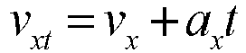

- In the formulas, n is a point, t is a future moment, x n0 and y n0 are initial positions of the point n, xnt and ynt are predicted positions at the moment t, vxt and vyt are predicted speeds at the moment t, ax and ay are respectively a transverse acceleration and a longitudinal acceleration of the obstacle at the current moment, and vx and vy are respectively a transverse speed and a longitudinal speed of the obstacle at the current moment.
- It should be noted that, points on the edges on which path planning is specifically performed in step 1 and step 2 need to be determined correspondingly according to a travel direction of the obstacle and a travel direction of the auto vehicle. For example, in
FIG. 2 , there is no need to determine a predicted obstacle path on a right-side edge of the auto vehicle. - Step 3. According to predicted auto vehicle paths of the auto vehicle and predicted obstacle paths of the obstacle, it is determined whether there are intersections between the predicted auto vehicle paths and the predicted obstacle paths. In a case that there are no intersections, step 4 is performed; and in a case that there are intersections, step 5 is performed.
- Step 4. There are no intersections between the predicted auto vehicle paths and the predicted obstacle paths, indicating that the obstacle is not about to collide with the auto vehicle in the Tpre time. In this case, a speed of the auto vehicle is not limited, and the auto vehicle may accelerate, decelerate, or maintain an original speed.
- Step 5. There are intersections between the predicted auto vehicle paths and the predicted obstacle paths, indicating that there is a possibility of collision between the obstacle and the auto vehicle in the Tpre time. In this case, positions of the intersections, predicted auto vehicle paths in which the intersections are located, and auto vehicle edge points corresponding to the intersections are determined, a length of a shortest predicted auto vehicle path between each intersection and its corresponding auto vehicle edge point at a current moment in the Tpre is selected as a minimum distance L tmin , a moment of the first intersection is used as a start moment tstart of a collision, and a moment of the last intersection is used as an end moment tend of the collision. The start moment tstart and the end moment tend may be calculated according to a moving speed of the obstacle and distances between the obstacle and the corresponding intersections.
- A status that the auto vehicle in a plurality of predicted auto vehicle paths is about to collide with the obstacle at the same time may occur at the specific moment t at which the collision occurs. A distance Lmt = imL 0, where m represents a serial number of a predicted auto vehicle path, and a position at which the vehicle body (for example, a front surface, or a side surface) collides with the obstacle can be determined through m; and im represents the number of discrete points on the predicted auto vehicle path m. A specific formula is:

- Step 6. A travel distance of the auto vehicle from tstart to tend is traversed, and formulas are as follows:


- In the formulas, St and νtcar are respectively an auto vehicle travel distance and a speed of the auto vehicle at the moment t, and νcar and acar are respectively an initial speed and an acceleration of the auto vehicle at the start moment.
- Step 7. It is determined, according to the auto vehicle travel distance St, a set front collision safety distance Slon, a set lateral collision safety distance Slat, and the minimum distance Ltmin (refers to the closest distance at which the auto vehicle is about to collide with the obstacle), whether the auto vehicle is about to collide with the obstacle.
- 1) Determine whether St - Slan ≤ L tmin: if yes, it is determined that the auto vehicle is not about to collide with the obstacle, and the auto vehicle is controlled to travel normally, and maintain a current acceleration to travel; or otherwise, it is determined that the auto vehicle is about to collide with the obstacle, and the auto vehicle should travel at an acceleration lower than the current acceleration.
The start moment is the earliest moment at which a vehicle may collide with an obstacle. In a case that a travel distance of the vehicle before the earliest moment at which the collision may occur is already greater than a distance between the vehicle and the earliest collision point at which the collision may occur (greater than and beyond the corresponding set safety distance), that is, a speed of the vehicle is fast enough for the vehicle to travel past and away from a path intersection with the obstacle, there is no longer a possibility of a collision between the vehicle and the obstacle. Therefore, a current acceleration can be maintained or an acceleration can be increased without a risk of a collision. In a case that the travel distance of the vehicle before the earliest moment at which the collision may occur is not greater than a distance between the vehicle and the earliest collision point at which the collision may occur (or a sufficient safety distance is not reserved), there is a possibility of a collision. Therefore, the acceleration should be reduced, to avoid a collision. - 2) Determine whether St - Slat > L tmin and t = tstart : if yes, it is determined that the auto vehicle is not about to collide with the obstacle and the auto vehicle travels preferentially, and the auto vehicle may travel at or above the current acceleration; or otherwise, it is determined that the auto vehicle is about to collide with the obstacle, and the auto vehicle should travel below the current acceleration.
- Before any moment between the start moment of a possible collision and the end moment of a possible collision, in a case that a travel distance of the vehicle remains less than a minimum distance of distances between the vehicle and collision points (and a sufficient set safety distance is reserved), the vehicle can maintain a current acceleration or reduce an acceleration without a risk of a collision. In a case that the travel distance of the vehicle is greater than or equal to the minimum distance of distances between the vehicle and the collision points (or the sufficient safety distance is not reserved), there is a possibility of a collision. Therefore, the acceleration should be reduced, to avoid a collision.
- On the whole, in the method, expected or planned trajectories of a vehicle are deflected along an outline of a frame of a vehicle body (a projection in a travel direction). Each trajectory means a trajectory through which a corresponding vehicle body contour point is about to move, similar to many tentacles that are generated from the vehicle body to detect whether there is an obstacle in a to-be-traveled area, just like whiskers of a cat. For prediction of an obstacle, a position of a frame of the obstacle at a future specific moment is predicted according to a current position, a movement state, and a size of the frame of the obstacle. In this way, it is determined, according to tentacle points positions of the auto vehicle and the position of the frame of the obstacle, which point is in the frame, which means to determine whether there is an interference, and further determine, according to a condition of a safety distance, whether a collision is about to occur for the control of the auto vehicle.
- Moreover, a moment, a distance, and a position at which the collision occurs may be obtained by using the method, and the obtained information is more comprehensive, so that the auto vehicle can decelerate for avoidance (including yielding) or travel normally (including traveling at a uniform speed or with an acceleration) according to the above information of the collision. In the method, collision detection is performed by using the tentacle algorithm. The detection method is simple and easy to implement, and requires a small amount of calculation.
- This embodiment provides a determination device for collision prediction of an autonomous vehicle, and the device includes a memory and a processor. The memory and the processor are electrically connected with each other in a direct or indirect manner, to achieve data transmission or interaction. The processor herein may be a vehicle controller, or a processor added to the vehicle. The processor added to the vehicle may be a general-purpose processor, for example, a central processing unit CPU, or another programmable logical device, for example, a digital signal processor DSP. The processor is configured to execute instructions stored in the memory to implement the determination method for collision prediction of an autonomous vehicle described in the method embodiment. Since the method has been described in detail in the method embodiment, details are not described herein again.
- Although the content of the present invention has been described in detail through the above preferred embodiments, it should be understood that the above description should not be considered as a limitation on the present invention. For a person skilled in the art, various modifications and replacements to the present invention will be apparent after reading the above content. Therefore, the protection scope of the present invention should be subject to the appended claims.
Claims (10)
- A determination method for collision prediction of an autonomous vehicle, comprising the following steps:1) planning predicted obstacle paths of points on edges of an obstacle according to movement of the obstacle, and planning predicted auto vehicle paths of points on edges of an auto vehicle according to movement of the auto vehicle;2) determining whether there are intersections between the predicted obstacle paths and the predicted auto vehicle paths: determining, in a case that there are intersections, positions of the intersections, predicted auto vehicle paths in which the intersections are located, and auto vehicle edge points corresponding to the intersections, selecting a length of a shortest predicted auto vehicle path between the each intersection and its corresponding auto vehicle edge point at a current moment as a minimum distance, using a moment of the first intersection as a start moment of a collision, and using a moment of the last intersection as an end moment of a collision; and3) determining, according to an auto vehicle travel distance, a set safety distance, and the minimum distance, whether the auto vehicle is about to collide with the obstacle, wherein the auto vehicle travel distance is a distance traveled by the auto vehicle from the current moment to any moment in a possible collision time period, and the possible collision time period is from the start moment to the end moment.
- The determination method for collision prediction of an autonomous vehicle according to claim 1, characterized in that the method further comprises: in step 3), determining whether a first difference between a travel distance of the auto vehicle at the start moment of the collision and the set safety distance is greater than the minimum distance, and in a case that the first difference is greater than the minimum distance, determining that the auto vehicle is not about to collide with the obstacle.
- The determination method for collision prediction of an autonomous vehicle according to claim 1 or 2, characterized in that the method further comprises: in step 3), determining whether a second difference between a travel distance of the auto vehicle at any moment between the start moment of the collision and the end moment of the collision and the set safety distance is less than or equal to the minimum distance, and determining, in a case that the second difference is less than or equal to the minimum distance, that the auto vehicle is not about to collide with the obstacle.
- The determination method for collision prediction of an autonomous vehicle according to claim 1, characterized in that the method further comprises: in step 2), determining, in a case that there are no intersections, that the auto vehicle is not about to collide with the obstacle, and controlling the auto vehicle to reduce an acceleration, increase an acceleration, or maintain a current acceleration to travel.
- The determination method for collision prediction of an autonomous vehicle according to claim 2, characterized in that the method further comprises: in step 3), controlling, in a case that the first difference is greater than the minimum distance, the auto vehicle to maintain a current acceleration to travel or increase an acceleration to travel.
- The determination method for collision prediction of an autonomous vehicle according to claim 3, characterized in that the method further comprises: in step 3), controlling, in a case that the second difference is less than or equal to the minimum distance, the auto vehicle to maintain a current acceleration to travel.
- The determination method for collision prediction of an autonomous vehicle according to claim 2, characterized in that the method further comprises: determining, in a case that the first difference is less than or equal to the minimum distance, that the auto vehicle is about to collide with the obstacle, and controlling the auto vehicle to reduce an acceleration to travel.
- The determination method for collision prediction of an autonomous vehicle according to claim 3, characterized in that the method further comprises: determining, in a case that the second difference is greater than the minimum distance, that the auto vehicle is about to collide with the obstacle, and controlling the auto vehicle to reduce an acceleration to travel.
- The determination method for collision prediction of an autonomous vehicle according to claim 1, characterized in that the method further comprises: in step 1), planning, according to the movement of the auto vehicle, the predicted auto vehicle paths of the points on the edges of the auto vehicle by using a tentacle algorithm.
- A determination device for collision prediction of an autonomous vehicle, comprising a memory and a processor, characterized in that the processor being configured to execute instructions stored in the memory, to implement the determination method for collision prediction of an autonomous vehicle according to any one of claims 1 to 9.
Applications Claiming Priority (2)
| Application Number | Priority Date | Filing Date | Title |
|---|---|---|---|
| CN201911398952.2A CN113119964B (en) | 2019-12-30 | 2019-12-30 | Collision prediction judgment method and device for automatic driving vehicle |
| PCT/CN2020/131002 WO2021135728A1 (en) | 2019-12-30 | 2020-11-24 | Determination method and device for collision prediction of autonomous vehicle |
Publications (4)
| Publication Number | Publication Date |
|---|---|
| EP4082848A1 true EP4082848A1 (en) | 2022-11-02 |
| EP4082848A4 EP4082848A4 (en) | 2023-07-19 |
| EP4082848C0 EP4082848C0 (en) | 2024-05-01 |
| EP4082848B1 EP4082848B1 (en) | 2024-05-01 |
Family
ID=76687273
Family Applications (1)
| Application Number | Title | Priority Date | Filing Date |
|---|---|---|---|
| EP20909407.7A Active EP4082848B1 (en) | 2019-12-30 | 2020-11-24 | Determination device for collision prediction of autonomous vehicle |
Country Status (3)
| Country | Link |
|---|---|
| EP (1) | EP4082848B1 (en) |
| CN (1) | CN113119964B (en) |
| WO (1) | WO2021135728A1 (en) |
Cited By (2)
| Publication number | Priority date | Publication date | Assignee | Title |
|---|---|---|---|---|
| WO2024056689A1 (en) * | 2022-09-14 | 2024-03-21 | Valeo Schalter Und Sensoren Gmbh | Method for calculating a predicted time until a possible collision between two motor vehicles, computer program, and driver assistance system |
| EP4603352A3 (en) * | 2024-06-28 | 2025-12-24 | Shanghai Horizon Intelligent Automotive Technology Co., Ltd. | Method and apparatus for determining time to collision, device, and storage medium |
Families Citing this family (44)
| Publication number | Priority date | Publication date | Assignee | Title |
|---|---|---|---|---|
| DE102021109661B4 (en) * | 2021-04-16 | 2023-03-09 | Avl Software And Functions Gmbh | Method for the geometric representation of a vehicle surface of a vehicle for collision detection |
| CN115691152A (en) * | 2021-07-29 | 2023-02-03 | 北京万集科技股份有限公司 | Traffic dispatching method and equipment for ramp junction |
| CN113442924A (en) * | 2021-08-03 | 2021-09-28 | 浙江吉利控股集团有限公司 | Vehicle track planning method and system |
| CN113335312B (en) * | 2021-08-06 | 2021-10-19 | 新石器慧通(北京)科技有限公司 | Obstacle-detouring driving method and device, electronic equipment and medium |
| CN113485383B (en) * | 2021-09-02 | 2021-12-31 | 北京三快在线科技有限公司 | Control method and control device of unmanned equipment |
| CN113734163A (en) * | 2021-09-07 | 2021-12-03 | 北京三快在线科技有限公司 | Control method, device, storage medium and electronic device for unmanned vehicle |
| CN113776550B (en) * | 2021-09-08 | 2024-04-16 | 京东鲲鹏(江苏)科技有限公司 | Route planning method and device |
| CN115230731B (en) * | 2021-09-13 | 2025-11-25 | 上海仙途智能科技有限公司 | Methods, devices, terminals and media for determining travel routes |
| CN113885525A (en) * | 2021-10-30 | 2022-01-04 | 重庆长安汽车股份有限公司 | A path planning method, system, vehicle and storage medium for self-driving vehicles to get out of trouble |
| CN114137964B (en) * | 2021-11-09 | 2024-05-31 | 长沙中联重科环境产业有限公司 | Vehicle posture and sweeping disc and road edge following control method, device, equipment and special vehicle |
| CN114237229B (en) * | 2021-11-26 | 2023-06-13 | 青岛德智汽车科技有限公司 | Unstructured road work vehicle path planning method based on empirical path fitting |
| CN114103893A (en) * | 2021-11-26 | 2022-03-01 | 河北春玖智能科技有限公司 | Unmanned vehicle trajectory prediction anti-collision method |
| CN115292796B (en) * | 2021-11-26 | 2023-06-02 | 上海仙途智能科技有限公司 | Collision detection method and device |
| CN114030486B (en) * | 2021-12-21 | 2024-05-28 | 阿波罗智联(北京)科技有限公司 | Track prediction method and device for dynamic obstacle, electronic equipment and storage medium |
| CN116409339A (en) * | 2021-12-30 | 2023-07-11 | 魔门塔(苏州)科技有限公司 | A method, device and medium for automatic driving speed planning based on forward targets |
| CN116409342A (en) * | 2021-12-30 | 2023-07-11 | 魔门塔(苏州)科技有限公司 | A method, device and medium for automatic parking speed planning |
| CN114235441A (en) * | 2021-12-31 | 2022-03-25 | 深兰人工智能(深圳)有限公司 | Unmanned vehicle real-time collision detection method and related device |
| CN114407919B (en) * | 2021-12-31 | 2023-06-02 | 武汉中海庭数据技术有限公司 | Collision detection method and system based on automatic driving |
| CN114187764B (en) * | 2022-02-16 | 2022-05-13 | 深圳佑驾创新科技有限公司 | Method for rapidly detecting collision risk degree aiming at VRU (virtual Router Unit) passing scene |
| CN114510053B (en) * | 2022-02-17 | 2025-03-21 | 北京京东乾石科技有限公司 | Robot planning path verification method, device, storage medium and electronic device |
| CN114537438B (en) * | 2022-03-07 | 2025-11-18 | 京东鲲鹏(江苏)科技有限公司 | Speed control methods, devices, control equipment and storage media |
| CN114537439B (en) * | 2022-03-14 | 2026-03-24 | 广州小鹏自动驾驶科技有限公司 | Autonomous driving speed planning methods, electronic devices, vehicles and storage media |
| CN119975360B (en) * | 2022-05-11 | 2025-12-23 | 阿波罗智能技术(北京)有限公司 | Control method and device for automatic driving vehicle, electronic equipment and storage medium |
| CN114882706B (en) * | 2022-05-31 | 2023-06-16 | 华中科技大学 | Circumferential anti-collision early warning method and system based on unstructured road surface |
| CN115092130B (en) * | 2022-06-16 | 2025-04-29 | 阿波罗智能技术(北京)有限公司 | Vehicle collision prediction method, device, electronic device, medium and vehicle |
| CN115167426B (en) * | 2022-07-15 | 2025-07-22 | 深圳市正浩创新科技股份有限公司 | Path planning method and device for multiple self-mobile devices and self-mobile device |
| CN115620554A (en) * | 2022-07-27 | 2023-01-17 | 潍柴智能科技有限公司 | Driving method and system for self-driving vehicles at intersections based on road test equipment |
| CN115092136B (en) * | 2022-07-27 | 2023-09-12 | 广州小鹏自动驾驶科技有限公司 | Vehicle speed planning method and device, vehicle and storage medium |
| CN115027464B (en) * | 2022-07-29 | 2025-02-07 | 西安电子科技大学芜湖研究院 | A collision detection method for autonomous driving based on directional bounding box |
| CN115407774B (en) * | 2022-08-25 | 2026-02-13 | 魔门塔(苏州)科技有限公司 | Driving route planning methods and devices, vehicles, storage media, and terminals |
| CN115214724B (en) * | 2022-09-20 | 2022-12-09 | 毫末智行科技有限公司 | Trajectory prediction method and apparatus, electronic device and storage medium |
| CN115534943A (en) * | 2022-10-10 | 2022-12-30 | 中国第一汽车股份有限公司 | Method and device for collision prediction between vehicle and vehicle to be monitored |
| CN115309168B (en) * | 2022-10-11 | 2023-01-10 | 天地科技股份有限公司 | A control method and device for an unmanned underground vehicle |
| CN115907245A (en) * | 2022-10-24 | 2023-04-04 | 劢微机器人科技(深圳)有限公司 | Collision detection method, device, equipment and storage medium for AGV scheduling |
| CN115355916B (en) * | 2022-10-24 | 2023-03-03 | 北京智行者科技股份有限公司 | Trajectory planning method, apparatus and computer-readable storage medium for moving tool |
| CN116612660B (en) * | 2023-04-10 | 2024-05-28 | 山东高速建设管理集团有限公司 | Method and equipment for early warning vehicle conflict in highway reconstruction and expansion construction area |
| CN116552515B (en) * | 2023-05-09 | 2025-10-10 | 联创汽车电子有限公司 | Vehicle collision time calculation method, system and storage medium |
| CN116279500B (en) * | 2023-05-24 | 2023-09-19 | 深圳联友科技有限公司 | A vehicle collision identification method |
| CN116719318A (en) * | 2023-06-05 | 2023-09-08 | 库卡机器人(广东)有限公司 | Collision detection method and device, autonomous mobile device, storage medium |
| CN116572994B (en) * | 2023-07-10 | 2023-09-22 | 之江实验室 | Vehicle speed planning method, device and computer-readable medium |
| CN117148848B (en) * | 2023-10-27 | 2024-01-26 | 上海伯镭智能科技有限公司 | An intelligent obstacle avoidance method and system for unmanned vehicles |
| CN118046926B (en) * | 2024-04-02 | 2025-02-18 | 重庆大学 | Vehicle running track prediction method for automatic driving system |
| CN119335559A (en) * | 2024-09-30 | 2025-01-21 | 东风商用车有限公司 | Collision detection method and device based on laser radar |
| CN119428759A (en) * | 2024-11-27 | 2025-02-14 | 易控智驾科技有限公司 | Autonomous driving vehicle control method, device and system, and autonomous driving vehicle |
Family Cites Families (21)
| Publication number | Priority date | Publication date | Assignee | Title |
|---|---|---|---|---|
| JP2002074594A (en) * | 2000-08-25 | 2002-03-15 | Alpine Electronics Inc | Obstacle detecting system |
| JP2007279892A (en) * | 2006-04-04 | 2007-10-25 | Honda Motor Co Ltd | Collision prediction system control apparatus, collision prediction method, and occupant protection system |
| US8812226B2 (en) * | 2009-01-26 | 2014-08-19 | GM Global Technology Operations LLC | Multiobject fusion module for collision preparation system |
| DE102010002105A1 (en) * | 2010-02-18 | 2011-08-18 | Robert Bosch GmbH, 70469 | Method for assisting a driver of a vehicle in a driving maneuver |
| DE102010051203B4 (en) * | 2010-11-12 | 2022-07-28 | Zf Active Safety Gmbh | Method for detecting critical driving situations in trucks or passenger vehicles, in particular for avoiding collisions |
| US8466807B2 (en) * | 2011-06-01 | 2013-06-18 | GM Global Technology Operations LLC | Fast collision detection technique for connected autonomous and manual vehicles |
| JP5754510B2 (en) * | 2011-09-26 | 2015-07-29 | トヨタ自動車株式会社 | Vehicle driving support system |
| CN103335658B (en) * | 2013-06-19 | 2016-09-14 | 华南农业大学 | A kind of autonomous vehicle barrier-avoiding method generated based on arc path |
| CN104882025B (en) * | 2015-05-13 | 2017-02-22 | 东华大学 | Crashing detecting and warning method based on vehicle network technology |
| KR101604447B1 (en) * | 2015-05-26 | 2016-03-28 | 주식회사 피엘케이 테크놀로지 | Forward collision warning system and method |
| JP6308186B2 (en) * | 2015-08-28 | 2018-04-11 | トヨタ自動車株式会社 | Collision avoidance support device |
| CN107672588B (en) * | 2017-08-29 | 2020-05-08 | 广州小鹏汽车科技有限公司 | An automatic parking path obstacle collision detection method, device and system |
| US10331135B2 (en) * | 2017-11-22 | 2019-06-25 | GM Global Technology Operations LLC | Systems and methods for maneuvering around obstacles in autonomous vehicles |
| CN108062600B (en) * | 2017-12-18 | 2021-06-18 | 北京星云互联科技有限公司 | A vehicle collision warning method and device based on rectangle modeling |
| JP7185408B2 (en) * | 2018-03-02 | 2022-12-07 | 本田技研工業株式会社 | vehicle controller |
| CN108536149B (en) * | 2018-04-25 | 2023-07-28 | 吉林大学 | An obstacle avoidance control method for unmanned vehicles based on Dubins path |
| US20190354781A1 (en) * | 2018-05-17 | 2019-11-21 | GM Global Technology Operations LLC | Method and system for determining an object location by using map information |
| CN109407673A (en) * | 2018-12-19 | 2019-03-01 | 清华大学苏州汽车研究院(吴江) | A kind of autonomous lane-change control method and system suitable for structured road |
| CN109960261B (en) | 2019-03-22 | 2020-07-03 | 北京理工大学 | Dynamic obstacle avoiding method based on collision detection |
| CN110065494B (en) * | 2019-04-09 | 2020-07-31 | 魔视智能科技(上海)有限公司 | A vehicle collision avoidance method based on wheel detection |
| CN110550029B (en) * | 2019-08-12 | 2021-02-09 | 华为技术有限公司 | Obstacle avoidance method and device |
-
2019
- 2019-12-30 CN CN201911398952.2A patent/CN113119964B/en active Active
-
2020
- 2020-11-24 WO PCT/CN2020/131002 patent/WO2021135728A1/en not_active Ceased
- 2020-11-24 EP EP20909407.7A patent/EP4082848B1/en active Active
Cited By (2)
| Publication number | Priority date | Publication date | Assignee | Title |
|---|---|---|---|---|
| WO2024056689A1 (en) * | 2022-09-14 | 2024-03-21 | Valeo Schalter Und Sensoren Gmbh | Method for calculating a predicted time until a possible collision between two motor vehicles, computer program, and driver assistance system |
| EP4603352A3 (en) * | 2024-06-28 | 2025-12-24 | Shanghai Horizon Intelligent Automotive Technology Co., Ltd. | Method and apparatus for determining time to collision, device, and storage medium |
Also Published As
| Publication number | Publication date |
|---|---|
| EP4082848A4 (en) | 2023-07-19 |
| CN113119964B (en) | 2022-08-02 |
| EP4082848C0 (en) | 2024-05-01 |
| CN113119964A (en) | 2021-07-16 |
| WO2021135728A1 (en) | 2021-07-08 |
| EP4082848B1 (en) | 2024-05-01 |
Similar Documents
| Publication | Publication Date | Title |
|---|---|---|
| EP4082848B1 (en) | Determination device for collision prediction of autonomous vehicle | |
| CN114126940B (en) | Electronic Controls | |
| CN112193244B (en) | Linear Constraint-Based Motion Planning Method for Autonomous Driving Vehicles | |
| EP3474254B1 (en) | Surrounding environment recognition device | |
| CN115571130B (en) | A vehicle lane change assist method and system based on lane reference lines | |
| US9308916B2 (en) | Driver-assistance system and method for operating the driver-assistance system | |
| KR20220054278A (en) | Travelling track prediction method and device for vehicle | |
| CN101529486B (en) | Cruise control plan evaluation device and method | |
| JP4416020B2 (en) | Travel plan generator | |
| CN114258366A (en) | Polyline profile representation for autonomous vehicles | |
| CN112955902A (en) | Vehicle trajectory modification for following | |
| CN111399512A (en) | Driving control method, driving control device and vehicle | |
| EP4397554B1 (en) | Vehicle safety control method and apparatus, electronic device, and storage medium | |
| JP2019148856A (en) | Vehicle controller | |
| JP3973008B2 (en) | Safe driving support device, method and recording medium | |
| JP2019144691A (en) | Vehicle control device | |
| CN113561992B (en) | Automatic driving vehicle track generation method, device, terminal equipment and medium | |
| CN114862158A (en) | Automatic driving automobile scene risk assessment method based on passable area | |
| DE112022001381T5 (en) | PROCESSING METHOD, PROCESSING SYSTEM AND PROCESSING PROGRAM | |
| CN113525375B (en) | A vehicle lane changing method and device based on artificial potential field method | |
| JP2019148857A (en) | Vehicle control device | |
| JP6838769B2 (en) | Surrounding environment recognition device, display control device | |
| JP7615068B2 (en) | Vehicle control device | |
| CN119611428B (en) | Method and device for optimizing predicted track of surrounding vehicle, vehicle and storage medium | |
| CN115376333A (en) | Intersection vehicle scheduling method and device and electronic equipment |
Legal Events
| Date | Code | Title | Description |
|---|---|---|---|
| STAA | Information on the status of an ep patent application or granted ep patent |
Free format text: STATUS: THE INTERNATIONAL PUBLICATION HAS BEEN MADE |
|
| PUAI | Public reference made under article 153(3) epc to a published international application that has entered the european phase |
Free format text: ORIGINAL CODE: 0009012 |
|
| STAA | Information on the status of an ep patent application or granted ep patent |
Free format text: STATUS: REQUEST FOR EXAMINATION WAS MADE |
|
| 17P | Request for examination filed |
Effective date: 20220728 |
|
| AK | Designated contracting states |
Kind code of ref document: A1 Designated state(s): AL AT BE BG CH CY CZ DE DK EE ES FI FR GB GR HR HU IE IS IT LI LT LU LV MC MK MT NL NO PL PT RO RS SE SI SK SM TR |
|
| DAV | Request for validation of the european patent (deleted) | ||
| DAX | Request for extension of the european patent (deleted) | ||
| A4 | Supplementary search report drawn up and despatched |
Effective date: 20230615 |
|
| RIC1 | Information provided on ipc code assigned before grant |
Ipc: B60W 60/00 20200101ALI20230609BHEP Ipc: B60W 30/095 20120101ALI20230609BHEP Ipc: G08G 1/16 20060101ALI20230609BHEP Ipc: G05D 1/02 20200101ALI20230609BHEP Ipc: B60W 30/08 20120101AFI20230609BHEP |
|
| GRAP | Despatch of communication of intention to grant a patent |
Free format text: ORIGINAL CODE: EPIDOSNIGR1 |
|
| STAA | Information on the status of an ep patent application or granted ep patent |
Free format text: STATUS: GRANT OF PATENT IS INTENDED |
|
| RIC1 | Information provided on ipc code assigned before grant |
Ipc: B60W 60/00 20200101ALI20240206BHEP Ipc: B60W 30/095 20120101ALI20240206BHEP Ipc: G08G 1/16 20060101ALI20240206BHEP Ipc: B60W 30/08 20120101AFI20240206BHEP |
|
| INTG | Intention to grant announced |
Effective date: 20240221 |
|
| GRAS | Grant fee paid |
Free format text: ORIGINAL CODE: EPIDOSNIGR3 |
|
| GRAA | (expected) grant |
Free format text: ORIGINAL CODE: 0009210 |
|
| STAA | Information on the status of an ep patent application or granted ep patent |
Free format text: STATUS: THE PATENT HAS BEEN GRANTED |
|
| AK | Designated contracting states |
Kind code of ref document: B1 Designated state(s): AL AT BE BG CH CY CZ DE DK EE ES FI FR GB GR HR HU IE IS IT LI LT LU LV MC MK MT NL NO PL PT RO RS SE SI SK SM TR |
|
| REG | Reference to a national code |
Ref country code: GB Ref legal event code: FG4D |
|
| REG | Reference to a national code |
Ref country code: CH Ref legal event code: EP |
|
| REG | Reference to a national code |
Ref country code: IE Ref legal event code: FG4D |
|
| REG | Reference to a national code |
Ref country code: DE Ref legal event code: R096 Ref document number: 602020030435 Country of ref document: DE |
|
| U01 | Request for unitary effect filed |
Effective date: 20240515 |
|
| U07 | Unitary effect registered |
Designated state(s): AT BE BG DE DK EE FI FR IT LT LU LV MT NL PT SE SI Effective date: 20240528 |
|
| PG25 | Lapsed in a contracting state [announced via postgrant information from national office to epo] |
Ref country code: IS Free format text: LAPSE BECAUSE OF FAILURE TO SUBMIT A TRANSLATION OF THE DESCRIPTION OR TO PAY THE FEE WITHIN THE PRESCRIBED TIME-LIMIT Effective date: 20240901 |
|
| PG25 | Lapsed in a contracting state [announced via postgrant information from national office to epo] |
Ref country code: HR Free format text: LAPSE BECAUSE OF FAILURE TO SUBMIT A TRANSLATION OF THE DESCRIPTION OR TO PAY THE FEE WITHIN THE PRESCRIBED TIME-LIMIT Effective date: 20240501 |
|
| PG25 | Lapsed in a contracting state [announced via postgrant information from national office to epo] |
Ref country code: GR Free format text: LAPSE BECAUSE OF FAILURE TO SUBMIT A TRANSLATION OF THE DESCRIPTION OR TO PAY THE FEE WITHIN THE PRESCRIBED TIME-LIMIT Effective date: 20240802 |
|
| PG25 | Lapsed in a contracting state [announced via postgrant information from national office to epo] |
Ref country code: ES Free format text: LAPSE BECAUSE OF FAILURE TO SUBMIT A TRANSLATION OF THE DESCRIPTION OR TO PAY THE FEE WITHIN THE PRESCRIBED TIME-LIMIT Effective date: 20240501 |
|
| PG25 | Lapsed in a contracting state [announced via postgrant information from national office to epo] |
Ref country code: PL Free format text: LAPSE BECAUSE OF FAILURE TO SUBMIT A TRANSLATION OF THE DESCRIPTION OR TO PAY THE FEE WITHIN THE PRESCRIBED TIME-LIMIT Effective date: 20240501 |
|
| PG25 | Lapsed in a contracting state [announced via postgrant information from national office to epo] |
Ref country code: PL Free format text: LAPSE BECAUSE OF FAILURE TO SUBMIT A TRANSLATION OF THE DESCRIPTION OR TO PAY THE FEE WITHIN THE PRESCRIBED TIME-LIMIT Effective date: 20240501 Ref country code: NO Free format text: LAPSE BECAUSE OF FAILURE TO SUBMIT A TRANSLATION OF THE DESCRIPTION OR TO PAY THE FEE WITHIN THE PRESCRIBED TIME-LIMIT Effective date: 20240801 Ref country code: IS Free format text: LAPSE BECAUSE OF FAILURE TO SUBMIT A TRANSLATION OF THE DESCRIPTION OR TO PAY THE FEE WITHIN THE PRESCRIBED TIME-LIMIT Effective date: 20240901 Ref country code: HR Free format text: LAPSE BECAUSE OF FAILURE TO SUBMIT A TRANSLATION OF THE DESCRIPTION OR TO PAY THE FEE WITHIN THE PRESCRIBED TIME-LIMIT Effective date: 20240501 Ref country code: GR Free format text: LAPSE BECAUSE OF FAILURE TO SUBMIT A TRANSLATION OF THE DESCRIPTION OR TO PAY THE FEE WITHIN THE PRESCRIBED TIME-LIMIT Effective date: 20240802 Ref country code: ES Free format text: LAPSE BECAUSE OF FAILURE TO SUBMIT A TRANSLATION OF THE DESCRIPTION OR TO PAY THE FEE WITHIN THE PRESCRIBED TIME-LIMIT Effective date: 20240501 Ref country code: RS Free format text: LAPSE BECAUSE OF FAILURE TO SUBMIT A TRANSLATION OF THE DESCRIPTION OR TO PAY THE FEE WITHIN THE PRESCRIBED TIME-LIMIT Effective date: 20240801 |
|
| U20 | Renewal fee for the european patent with unitary effect paid |
Year of fee payment: 5 Effective date: 20241128 |
|
| PG25 | Lapsed in a contracting state [announced via postgrant information from national office to epo] |
Ref country code: CZ Free format text: LAPSE BECAUSE OF FAILURE TO SUBMIT A TRANSLATION OF THE DESCRIPTION OR TO PAY THE FEE WITHIN THE PRESCRIBED TIME-LIMIT Effective date: 20240501 |
|
| PG25 | Lapsed in a contracting state [announced via postgrant information from national office to epo] |
Ref country code: SK Free format text: LAPSE BECAUSE OF FAILURE TO SUBMIT A TRANSLATION OF THE DESCRIPTION OR TO PAY THE FEE WITHIN THE PRESCRIBED TIME-LIMIT Effective date: 20240501 Ref country code: RO Free format text: LAPSE BECAUSE OF FAILURE TO SUBMIT A TRANSLATION OF THE DESCRIPTION OR TO PAY THE FEE WITHIN THE PRESCRIBED TIME-LIMIT Effective date: 20240501 |
|
| PG25 | Lapsed in a contracting state [announced via postgrant information from national office to epo] |
Ref country code: SM Free format text: LAPSE BECAUSE OF FAILURE TO SUBMIT A TRANSLATION OF THE DESCRIPTION OR TO PAY THE FEE WITHIN THE PRESCRIBED TIME-LIMIT Effective date: 20240501 |
|
| PG25 | Lapsed in a contracting state [announced via postgrant information from national office to epo] |
Ref country code: SM Free format text: LAPSE BECAUSE OF FAILURE TO SUBMIT A TRANSLATION OF THE DESCRIPTION OR TO PAY THE FEE WITHIN THE PRESCRIBED TIME-LIMIT Effective date: 20240501 Ref country code: SK Free format text: LAPSE BECAUSE OF FAILURE TO SUBMIT A TRANSLATION OF THE DESCRIPTION OR TO PAY THE FEE WITHIN THE PRESCRIBED TIME-LIMIT Effective date: 20240501 Ref country code: RO Free format text: LAPSE BECAUSE OF FAILURE TO SUBMIT A TRANSLATION OF THE DESCRIPTION OR TO PAY THE FEE WITHIN THE PRESCRIBED TIME-LIMIT Effective date: 20240501 Ref country code: CZ Free format text: LAPSE BECAUSE OF FAILURE TO SUBMIT A TRANSLATION OF THE DESCRIPTION OR TO PAY THE FEE WITHIN THE PRESCRIBED TIME-LIMIT Effective date: 20240501 |
|
| REG | Reference to a national code |
Ref country code: DE Ref legal event code: R097 Ref document number: 602020030435 Country of ref document: DE |
|
| PLBE | No opposition filed within time limit |
Free format text: ORIGINAL CODE: 0009261 |
|
| STAA | Information on the status of an ep patent application or granted ep patent |
Free format text: STATUS: NO OPPOSITION FILED WITHIN TIME LIMIT |
|
| 26N | No opposition filed |
Effective date: 20250204 |
|
| REG | Reference to a national code |
Ref country code: CH Ref legal event code: PL |
|
| PG25 | Lapsed in a contracting state [announced via postgrant information from national office to epo] |
Ref country code: MC Free format text: LAPSE BECAUSE OF FAILURE TO SUBMIT A TRANSLATION OF THE DESCRIPTION OR TO PAY THE FEE WITHIN THE PRESCRIBED TIME-LIMIT Effective date: 20240501 |
|
| REG | Reference to a national code |
Ref country code: CH Ref legal event code: PL |
|
| PG25 | Lapsed in a contracting state [announced via postgrant information from national office to epo] |
Ref country code: CH Free format text: LAPSE BECAUSE OF NON-PAYMENT OF DUE FEES Effective date: 20241130 |
|
| PG25 | Lapsed in a contracting state [announced via postgrant information from national office to epo] |
Ref country code: IE Free format text: LAPSE BECAUSE OF NON-PAYMENT OF DUE FEES Effective date: 20241124 |
|
| U20 | Renewal fee for the european patent with unitary effect paid |
Year of fee payment: 6 Effective date: 20251128 |
|
| PGFP | Annual fee paid to national office [announced via postgrant information from national office to epo] |
Ref country code: GB Payment date: 20251119 Year of fee payment: 6 |
|
| PG25 | Lapsed in a contracting state [announced via postgrant information from national office to epo] |
Ref country code: HU Free format text: LAPSE BECAUSE OF FAILURE TO SUBMIT A TRANSLATION OF THE DESCRIPTION OR TO PAY THE FEE WITHIN THE PRESCRIBED TIME-LIMIT; INVALID AB INITIO Effective date: 20201124 |
|
| PG25 | Lapsed in a contracting state [announced via postgrant information from national office to epo] |
Ref country code: CY Free format text: LAPSE BECAUSE OF FAILURE TO SUBMIT A TRANSLATION OF THE DESCRIPTION OR TO PAY THE FEE WITHIN THE PRESCRIBED TIME-LIMIT; INVALID AB INITIO Effective date: 20201124 |