EP4082672A1 - Spray fan - Google Patents
Spray fan Download PDFInfo
- Publication number
- EP4082672A1 EP4082672A1 EP21795346.2A EP21795346A EP4082672A1 EP 4082672 A1 EP4082672 A1 EP 4082672A1 EP 21795346 A EP21795346 A EP 21795346A EP 4082672 A1 EP4082672 A1 EP 4082672A1
- Authority
- EP
- European Patent Office
- Prior art keywords
- fan
- nozzle
- water
- assembly
- misting
- Prior art date
- Legal status (The legal status is an assumption and is not a legal conclusion. Google has not performed a legal analysis and makes no representation as to the accuracy of the status listed.)
- Granted
Links
Images








Classifications
-
- B—PERFORMING OPERATIONS; TRANSPORTING
- B05—SPRAYING OR ATOMISING IN GENERAL; APPLYING FLUENT MATERIALS TO SURFACES, IN GENERAL
- B05B—SPRAYING APPARATUS; ATOMISING APPARATUS; NOZZLES
- B05B9/00—Spraying apparatus for discharge of liquids or other fluent material, without essentially mixing with gas or vapour
- B05B9/03—Spraying apparatus for discharge of liquids or other fluent material, without essentially mixing with gas or vapour characterised by means for supplying liquid or other fluent material
-
- F—MECHANICAL ENGINEERING; LIGHTING; HEATING; WEAPONS; BLASTING
- F04—POSITIVE - DISPLACEMENT MACHINES FOR LIQUIDS; PUMPS FOR LIQUIDS OR ELASTIC FLUIDS
- F04D—NON-POSITIVE-DISPLACEMENT PUMPS
- F04D29/00—Details, component parts, or accessories
- F04D29/70—Suction grids; Strainers; Dust separation; Cleaning
- F04D29/701—Suction grids; Strainers; Dust separation; Cleaning especially adapted for elastic fluid pumps
- F04D29/705—Adding liquids
-
- B—PERFORMING OPERATIONS; TRANSPORTING
- B01—PHYSICAL OR CHEMICAL PROCESSES OR APPARATUS IN GENERAL
- B01F—MIXING, e.g. DISSOLVING, EMULSIFYING OR DISPERSING
- B01F23/00—Mixing according to the phases to be mixed, e.g. dispersing or emulsifying
- B01F23/20—Mixing gases with liquids
- B01F23/23—Mixing gases with liquids by introducing gases into liquid media, e.g. for producing aerated liquids
-
- B—PERFORMING OPERATIONS; TRANSPORTING
- B05—SPRAYING OR ATOMISING IN GENERAL; APPLYING FLUENT MATERIALS TO SURFACES, IN GENERAL
- B05B—SPRAYING APPARATUS; ATOMISING APPARATUS; NOZZLES
- B05B1/00—Nozzles, spray heads or other outlets, with or without auxiliary devices such as valves, heating means
- B05B1/30—Nozzles, spray heads or other outlets, with or without auxiliary devices such as valves, heating means designed to control volume of flow, e.g. with adjustable passages
- B05B1/3006—Nozzles, spray heads or other outlets, with or without auxiliary devices such as valves, heating means designed to control volume of flow, e.g. with adjustable passages the controlling element being actuated by the pressure of the fluid to be sprayed
-
- B—PERFORMING OPERATIONS; TRANSPORTING
- B05—SPRAYING OR ATOMISING IN GENERAL; APPLYING FLUENT MATERIALS TO SURFACES, IN GENERAL
- B05B—SPRAYING APPARATUS; ATOMISING APPARATUS; NOZZLES
- B05B15/00—Details of spraying plant or spraying apparatus not otherwise provided for; Accessories
- B05B15/60—Arrangements for mounting, supporting or holding spraying apparatus
- B05B15/65—Mounting arrangements for fluid connection of the spraying apparatus or its outlets to flow conduits
-
- B—PERFORMING OPERATIONS; TRANSPORTING
- B05—SPRAYING OR ATOMISING IN GENERAL; APPLYING FLUENT MATERIALS TO SURFACES, IN GENERAL
- B05B—SPRAYING APPARATUS; ATOMISING APPARATUS; NOZZLES
- B05B7/00—Spraying apparatus for discharge of liquids or other fluent materials from two or more sources, e.g. of liquid and air, of powder and gas
- B05B7/0075—Nozzle arrangements in gas streams
-
- B—PERFORMING OPERATIONS; TRANSPORTING
- B05—SPRAYING OR ATOMISING IN GENERAL; APPLYING FLUENT MATERIALS TO SURFACES, IN GENERAL
- B05B—SPRAYING APPARATUS; ATOMISING APPARATUS; NOZZLES
- B05B7/00—Spraying apparatus for discharge of liquids or other fluent materials from two or more sources, e.g. of liquid and air, of powder and gas
- B05B7/0081—Apparatus supplied with low pressure gas, e.g. "hvlp"-guns; air supplied by a fan
-
- B—PERFORMING OPERATIONS; TRANSPORTING
- B05—SPRAYING OR ATOMISING IN GENERAL; APPLYING FLUENT MATERIALS TO SURFACES, IN GENERAL
- B05B—SPRAYING APPARATUS; ATOMISING APPARATUS; NOZZLES
- B05B7/00—Spraying apparatus for discharge of liquids or other fluent materials from two or more sources, e.g. of liquid and air, of powder and gas
- B05B7/24—Spraying apparatus for discharge of liquids or other fluent materials from two or more sources, e.g. of liquid and air, of powder and gas with means, e.g. a container, for supplying liquid or other fluent material to a discharge device
- B05B7/2486—Spraying apparatus for discharge of liquids or other fluent materials from two or more sources, e.g. of liquid and air, of powder and gas with means, e.g. a container, for supplying liquid or other fluent material to a discharge device with means for supplying liquid or other fluent material to several discharge devices
-
- F—MECHANICAL ENGINEERING; LIGHTING; HEATING; WEAPONS; BLASTING
- F04—POSITIVE - DISPLACEMENT MACHINES FOR LIQUIDS; PUMPS FOR LIQUIDS OR ELASTIC FLUIDS
- F04D—NON-POSITIVE-DISPLACEMENT PUMPS
- F04D19/00—Axial-flow pumps
- F04D19/002—Axial flow fans
-
- F—MECHANICAL ENGINEERING; LIGHTING; HEATING; WEAPONS; BLASTING
- F04—POSITIVE - DISPLACEMENT MACHINES FOR LIQUIDS; PUMPS FOR LIQUIDS OR ELASTIC FLUIDS
- F04D—NON-POSITIVE-DISPLACEMENT PUMPS
- F04D25/00—Pumping installations or systems
- F04D25/02—Units comprising pumps and their driving means
- F04D25/06—Units comprising pumps and their driving means the pump being electrically driven
- F04D25/0673—Battery powered
-
- F—MECHANICAL ENGINEERING; LIGHTING; HEATING; WEAPONS; BLASTING
- F04—POSITIVE - DISPLACEMENT MACHINES FOR LIQUIDS; PUMPS FOR LIQUIDS OR ELASTIC FLUIDS
- F04D—NON-POSITIVE-DISPLACEMENT PUMPS
- F04D29/00—Details, component parts, or accessories
- F04D29/70—Suction grids; Strainers; Dust separation; Cleaning
- F04D29/701—Suction grids; Strainers; Dust separation; Cleaning especially adapted for elastic fluid pumps
- F04D29/703—Suction grids; Strainers; Dust separation; Cleaning especially adapted for elastic fluid pumps specially for fans, e.g. fan guards
-
- F—MECHANICAL ENGINEERING; LIGHTING; HEATING; WEAPONS; BLASTING
- F04—POSITIVE - DISPLACEMENT MACHINES FOR LIQUIDS; PUMPS FOR LIQUIDS OR ELASTIC FLUIDS
- F04D—NON-POSITIVE-DISPLACEMENT PUMPS
- F04D25/00—Pumping installations or systems
- F04D25/02—Units comprising pumps and their driving means
- F04D25/08—Units comprising pumps and their driving means the working fluid being air, e.g. for ventilation
-
- Y—GENERAL TAGGING OF NEW TECHNOLOGICAL DEVELOPMENTS; GENERAL TAGGING OF CROSS-SECTIONAL TECHNOLOGIES SPANNING OVER SEVERAL SECTIONS OF THE IPC; TECHNICAL SUBJECTS COVERED BY FORMER USPC CROSS-REFERENCE ART COLLECTIONS [XRACs] AND DIGESTS
- Y02—TECHNOLOGIES OR APPLICATIONS FOR MITIGATION OR ADAPTATION AGAINST CLIMATE CHANGE
- Y02B—CLIMATE CHANGE MITIGATION TECHNOLOGIES RELATED TO BUILDINGS, e.g. HOUSING, HOUSE APPLIANCES OR RELATED END-USER APPLICATIONS
- Y02B30/00—Energy efficient heating, ventilation or air conditioning [HVAC]
- Y02B30/54—Free-cooling systems
Definitions
- the present disclosure relates to a fan and, in particular, to a misting fan.
- the existing misting fan generally uses external mains electricity as a power source so that the misting fan can only be used where there is a socket, which reduces the convenience to use the misting fan and also limits the places where the misting fan can be used. Moreover, a nozzle on the existing misting fan is easily clogged and then needs to be replaced by a new nozzle, which increases the cost of use and also reduces operation efficiency. Especially when the misting fan is operating, if the nozzle is clogged and cannot be replaced in time, the misting fan cannot operate, either. Further, if the nozzle of the misting fan is not completely clogged, a user may not notice that the nozzle has a problem and will not replace the nozzle in time, thereby seriously affecting the cooling effect of the misting fan.
- an object of the present disclosure is to provide a misting fan that is convenient to carry and easy to clean.
- a misting fan includes a nozzle, a fan assembly, and a support assembly.
- the nozzle is configured to spray water.
- the fan assembly includes fan blades and an electric motor configured to drive the fan blades to rotate.
- the support assembly is configured to support the fan assembly.
- the support assembly is formed with a coupling portion for detachably coupling a battery pack.
- the nozzle is disposed on the fan assembly or the support assembly and includes a nozzle body and a second part.
- the nozzle body includes a first part formed with a first surface.
- the second part is detachably installed to the nozzle body and formed with a second surface. In the case where the second part is installed to the nozzle body, a water flow channel is formed between the second surface and the first surface; and in the case where the second part is detached from the nozzle body, the first surface is at least partially exposed to be cleaned.
- the nozzle is detachably installed to the support assembly.
- the fan assembly further includes a fan cover surrounding the fan blades, where the nozzle is detachably installed to the fan cover.
- the nozzle body further includes a support piece configured to support the first part, where the first part and the support piece are detachably connected.
- the second surface is at least partially exposed to be cleaned.
- a connection piece is configured to detachably connect the second part to the nozzle body; the second part is formed with a water outlet hole through which the water is sprayed to an outside; and the second part and the connection piece are detachably connected.
- the second part is formed with a water outlet hole through which the water is sprayed to an outside, where a diameter of the water outlet hole is greater than or equal to 0.2 mm and less than or equal to 0.4 mm.
- the second part is formed with a water outlet hole through which the water is sprayed to an outside, where the water outlet hole has a centerline; where the first surface surrounds the centerline, and the second surface surrounds the centerline.
- the nozzle body further includes a support piece configured to support the first part and formed with a water inlet hole and an accommodation cavity in which the first part is disposed.
- the first part is movably disposed in the accommodation cavity.
- the nozzle body further includes an elastic piece disposed in the accommodation cavity and a spring supported between the elastic piece and the first part; where the accommodation cavity is formed with a hole communicating with the water inlet hole on a bottom surface of the accommodation cavity, and the elastic piece is supported at the hole.
- the nozzle has a water outlet hole centered on a centerline, where a section line of the first surface in a plane passing through the centerline obliquely intersects with the centerline, and a section line of the second surface in the plane also obliquely intersects with the centerline.
- the first surface is a part of one conical surface and the second surface is a part of another conical surface.
- the nozzle body further includes a support piece configured to support the first part, where the support piece is formed with a threaded portion configured to detachably install the nozzle to the fan assembly or the support assembly, and a sealing ring is disposed on the support piece.
- the misting fan further includes the battery pack detachably installed to the coupling portion, a waterway system including a water pipe connected to the nozzle, and a pump connected to the water pipe; where output water pressure of the pump is greater than or equal to 40 psi and less than or equal to 120 psi.
- a misting fan includes a nozzle, a fan assembly, and a support assembly.
- the nozzle is configured to spray water.
- the fan assembly includes fan blades and an electric motor configured to drive the fan blades to rotate.
- the support assembly is configured to support the fan assembly.
- the support assembly is formed with a coupling portion for detachably coupling a battery pack.
- the nozzle is disposed on the fan assembly or the support assembly and includes a nozzle body and a second part.
- the nozzle body includes a first part formed with a first surface.
- the second part is movably installed to the nozzle body and formed with a second surface.
- a water flow channel is formed between the second surface and the first surface; and in the case where the second part moves to a second position relative to the first part, the first surface is at least partially exposed to be cleaned.
- a misting fan includes a nozzle, a fan assembly, and a support assembly.
- the nozzle is configured to spray water.
- the fan assembly includes fan blades and an electric motor configured to drive the fan blades to rotate.
- the support assembly is configured to support the fan assembly.
- the support assembly is formed with a coupling portion for detachably coupling a battery pack.
- the nozzle is disposed on the fan assembly or the support assembly and includes a first part and a second part. The first part is formed with a first surface. The second part is movable relative to the first part and formed with a second surface.
- a water flow channel is formed between the second surface and the first surface; and in the case where the second part moves to a second position relative to the first part, the first surface or the second surface is at least partially exposed to be cleaned.
- the second part is formed with a water outlet hole through which the water is sprayed to an outside, where a diameter of the water outlet hole is greater than or equal to 0.2 mm and less than or equal to 0.4 mm.
- the second part is formed with the water outlet hole through which the water is sprayed to the outside, and the water outlet hole has a centerline; where the first surface surrounds the centerline and the second surface surrounds the centerline.
- the first surface is a part of one conical surface and the second surface is a part of another conical surface.
- the present disclosure has the following beneficial effects: the misting fan is more convenient to use, more widely used, and convenient for a user to clean.
- a misting fan 100 shown in FIG. 1 in embodiment one is configured to spray water.
- the water sprayed into air can cool the environment.
- the misting fan 100 may be applied to outdoor places such as a basketball court, a park, and a playground. When used outdoors, the misting fan 100 may use water in a bucket.
- the misting fan 100 may also be applied to indoor places such as a shopping mall, a factory, and a warehouse. When used indoors, the misting fan 100 may be connected to a tap water pipe.
- the misting fan 100 includes a main machine 10 and a first battery pack 101, where the first battery pack 101 may be detachably installed to the main machine 10. In this manner, the misting fan 100 can be conveniently carried outdoors for operation.
- the misting fan 100 with the first battery pack 101 is more convenient to use especially in places where there is no convenient power source such as the park.
- the main machine 10 includes a support assembly 10a, a fan assembly 13, and a nozzle 14.
- the support assembly 10a is configured to support the fan assembly 13 and the nozzle 14, and the support assembly 10a includes a base 11 and a support arm 12.
- the base 11 is configured to support the entire misting fan 100 so that the misting fan 100 is placed on a workbench.
- the support arm 12 is connected to the base 11 and disposed at least partially above the base 11.
- An end of the support arm 12 is connected to the base 11, and the other end of the support arm 12 is connected to the fan assembly 13 so that the support arm 12 supports the fan assembly 13.
- the fan assembly 13 includes fan blades 131 and an electric motor 132, where the electric motor 132 is configured to drive the fan blades 131 to rotate around an electric motor axis 100a.
- the nozzle 14 is configured to spray the water and installed to the support assembly 10a or the fan assembly 13.
- the misting fan 100 is started, the water is sprayed from the nozzle 14 into an external environment, and the fan blades 131 rotate to generate an airflow to blow the water sprayed from the nozzle 14 into the air so that the temperature of the air in the environment drops.
- the first battery pack 101 is detachably installed to the support assembly 10a.
- the first battery pack 101 is installed to the base 11. It is to be understood that, in other embodiments, the first battery pack 101 may also be installed to the support arm 12. It is to be understood that all parts other than the fan blades 131 and the electric motor 132 driving the fan blades 131 to rotate in the misting fan 100 may be considered to belong to the support assembly 10a. In this manner, the first battery pack 101 may be installed to any part of the support assembly 10a.
- the base 11 is formed with a coupling portion 111 for coupling the first battery pack 101.
- the coupling portion 111 surrounds and forms a battery compartment 111a, where the first battery pack 101 is capable of being installed in the battery compartment 111a.
- a second battery pack 102 is also capable of being installed in the battery compartment 111a.
- the first battery pack 101 has a first volume and a first capacity
- the second battery pack 102 has a second volume and a second capacity.
- the first volume is greater than the second volume
- the first capacity is greater than the second capacity.
- the support assembly 10a further includes a battery cover 112, and the first battery pack 101 is connected to the coupling portion 111.
- the battery cover 112 has an open state and a closed state relative to the coupling portion 111.
- the battery cover 112 allows the first battery pack 101 or the second battery pack 102 to be detached from the battery compartment 111a.
- the battery cover 112 and the coupling portion 111 jointly surround and form an accommodation cavity 113 for accommodating the first battery pack 101 or the second battery pack 102, and at this time, the battery cover 112 covers the battery compartment 111a.
- An access terminal 111b is disposed in the battery compartment 111a and electrically connected to the first battery pack 101 or the second battery pack 102.
- the first battery pack 101 is capable of being inserted into the battery compartment 111a
- the second battery pack 102 is also capable of being inserted into the battery compartment 111a.
- a user can selectively insert the first battery pack 101 or the second battery pack 102 into the battery compartment 111a according to requirements.
- the battery compartment 111a can fit with not only the first battery pack 101 but also the second battery pack 102. Therefore, the user can install battery packs with different volumes or different capacities according to requirements, which improves the adaptability of the misting fan 100 and prolongs the lifetime of the misting fan 100.
- the battery cover 112 and the coupling portion 111 surround and form the accommodation cavity 113, and the accommodation cavity 113 can accommodate not only the first battery pack 101 but also the second battery pack 102. In this manner, the user can select and install a battery pack with a larger volume or a larger capacity to the misting fan 100.
- the first battery pack 101 and the second battery pack 102 have the same nominal voltage, a nominal voltage of the first battery pack 101 is greater than or equal to 20V, and a nominal voltage of the second battery pack 102 is greater than or equal to 20V. Further, the nominal voltage of the first battery pack 101 is greater than or equal to 40V, and the nominal voltage of the second battery pack 102 is greater than or equal to 40V so that the first battery pack 101 or the second battery pack 102 outputs greater power and has a greater capacity, thereby improving the operation time and efficiency of the misting fan 100.
- the battery compartment 111a of the main machine 10 may also be adapted to a third battery pack 103, and the third battery pack 103 may have a third volume and a third capacity, thereby further improving the adaptability of the misting fan 100.
- the support arm 12 supports the fan assembly 13 on an upper side of the base 11, and the fan assembly 13 can rotate relative to the support arm 12.
- the coupling portion 111 is disposed on a lower side of the fan assembly 13.
- the first battery pack 101 When installed in the battery compartment 111a, the first battery pack 101 is located on the lower side of the fan assembly 13. In this manner, the coupling portion 111 does not interfere with the rotation of the fan assembly 13 and does not affect an air inlet region on a rear side of the fan assembly 13, thereby improving blowing efficiency.
- both the first battery pack 101 and the second battery pack 102 can be installed in the battery compartment 111a. Due to a relatively large volume of the first battery pack 101, a relatively large volume is provided in the battery compartment 111a.
- the first battery pack 101 is inserted into the battery compartment 111a along a direction of a first straight line 100b, that is, the coupling portion 111 is formed with a guide structure 111c guiding the first battery pack 101 or the second battery pack 102 to be coupled to the battery compartment 111a along the direction of the first straight line 100b.
- the first straight line 100b obliquely intersects with the plane.
- the coupling portion 111 can be prevented from shielding the air inlet region of the fan assembly 13 as much as possible.
- the volume in the battery compartment 111a can be increased so that the battery pack with the larger volume or the larger capacity can be installed to the misting fan 100.
- the first straight line 100b intersects with the plane so as to form an angle greater than 0 degrees and less than or equal to 30 degrees.
- a height of the battery compartment 111a in the up-and-down direction is greater than or equal to 60 mm and less than or equal to 100 mm. In this manner, the volume in the battery compartment 111a is large enough so that the battery compartment 111a can be adapted to the battery pack with the larger volume.
- the battery compartment 111a is disposed at least partially on the rear side of the fan assembly 13 so that an operation assembly 15 shown in FIG. 7 can be disposed in a region of the base 11 on a front side of the fan assembly 13.
- the battery compartment 111a is open backwards, and the first battery pack 101 or the second battery pack 102 is inserted into the battery compartment 111a from a rear side of the main machine 10.
- the battery cover 112 is rotatably connected to the coupling portion 111 around a first axis 100c.
- the first axis 100c is parallel to the plane.
- the user can open the battery cover 112 backwards so that the battery cover 112 is in the open state, and at this time, an outer surface of the battery cover 112 can be supported on the plane and the user does not need to hold the battery cover 112 with one hand and can conveniently detach the first battery pack 101 or the second battery pack 102, which improves the convenience of operation.
- the battery cover 112 is disposed on a rear side of the coupling portion 111, and the guide structure 111c guides the first battery pack 101 to be inserted into the battery compartment 111a in a direction oblique relative to the plane so that a region on the rear side of the coupling portion 111 is enough for the battery cover 112 to be opened.
- an angle through which the battery cover 112 rotates from a closed position to an open position is greater than 90 degrees. Therefore, when the battery cover 112 rotates to the open position, more space is reserved on an upper side of the battery cover 112 to allow the first battery pack 101 or the second battery pack 102 to be detached from the battery compartment 111a.
- the problem that when the misting fan 100 is placed on the plane, the battery cover 112 cannot be opened backwards to the open position to allow the first battery pack 101 to be detached from the battery compartment 111a can be avoided, that is, the problem that the battery cover 112 cannot be completely opened can be avoided.
- a water leakage hole 111d is disposed on a bottom surface of the battery compartment 111a. When entering the battery compartment 111a, water can flow out of the battery compartment 111a through the water leakage hole 111d.
- a part of the whole formed by the coupling portion 111 and the battery cover 112 that is disposed on the rear side of the fan assembly 13 has a dimension L in the front-and-rear direction, where the dimension L is greater than or equal to 60 mm and less than or equal to 100 mm so that the volume in the battery compartment 111a can be increased.
- a ratio of the first capacity of the first battery pack 101 to the second capacity of the second battery pack 102 is greater than or equal to 2.
- the ratio of the first capacity of the first battery pack 101 to the second capacity of the second battery pack 102 is greater than or equal to 3.
- the first capacity of the first battery pack 101 is also greater than 4.5 AH, thereby increasing the lifetime of the first battery pack 101 and increasing the operation duration of the misting fan 100.
- the first battery pack 101 may include a first cell group and a second cell group, where multiple cell units in the first cell group are connected in series. Multiple cell units may also be disposed in the second cell group. The first cell group and the second cell group are connected in parallel. That is, two cell groups connected in parallel are disposed in the first battery pack 101. Of course, it is to be understood that in other embodiments, three cell groups connected in parallel may be disposed in the first battery pack 101, thereby further increasing the lifetime of the first battery pack 101.
- the first capacity of the first battery pack 101 may also be greater than or equal to 5 AH.
- two nozzles 14 are provided, and two installation pieces 133 are connected on an outer side of the fan assembly 13.
- the two installation pieces 133 are respectively disposed on two sides of the fan assembly 13.
- the nozzle 14 is installed to the installation piece 133, and the whole formed by the nozzle 14 and the installation piece 133 can rotate with the fan assembly 13.
- the nozzle 14 is detachably installed to the installation piece 133. In this manner, when a water flow channel or a water outlet hole in the nozzle 14 is clogged by scale or debris, the user can conveniently detach the nozzle 14 to replace the nozzle 14 with a new one.
- the main machine 10 further includes a waterway system 16 configured to deliver external water to the nozzle 14.
- the waterway system 16 includes a first water pipe assembly 161 and a second water pipe assembly 162.
- the first water pipe assembly 161 is configured to deliver external water from a first external water source to the nozzle 14.
- the first external water source may specifically be a static water source.
- the static water source may be understood as water contained in a storage such as the bucket.
- the second water pipe assembly 162 is configured to deliver external water from a second external water source to the nozzle 14.
- the second external water source is specifically a flowing water source.
- the flowing water source may be understood as a water source with a certain flowrate such as tap water.
- the misting fan 100 When used in a place with the flowing water source, the misting fan 100 may use the flowing water source so that the misting fan 100 can operate for a relatively long time without replacing the water source. When used in a place where there is no flowing water source, the misting fan 100 may use the water in the storage, thereby improving the convenience to use the misting fan 100.
- the first water pipe assembly 161 includes a first water pipe 161a, a third water pipe 161b, and a first connection piece 161c.
- the misting fan 100 further includes a pump 163 installed to the first water pipe assembly 161.
- the first water pipe 161a includes a first end 161d and a third end 161e.
- the first connection piece 161c is installed to the first end 161d of the first water pipe 161a, and the first connection piece 161c is configured to be connected to the first external water source.
- the second end 161c of the first water pipe 161a is connected to an input end of the pump 163, and the third water pipe 161b is connected to an output end of the pump 163.
- the pump 163 pumps the water in the storage into the first water pipe 161a and then outputs the water to the third water pipe 161b.
- the base 11 surrounds and forms an accommodation space 11a, and the pump 163 is disposed in the accommodation space 11a.
- the battery compartment 111a is also formed by the base 11. In this embodiment, the accommodation space 11a and the battery compartment 111a are disposed separately so that water vapor can be prevented from entering the battery compartment 111a.
- the second water pipe assembly 162 includes a second water pipe 162a and a second connection piece 162b, and the second connection piece 162b is configured to be connected to the second external water source.
- the second water pipe 162a includes a second end 162c and a fourth end 162d, and the second connection piece 162b is installed to the second end 162c of the second water pipe 162a.
- a part of the first water pipe assembly 161 is disposed in the base 11 and a part of the first water pipe assembly 161 is disposed in the fan assembly 13.
- the second water pipe assembly 162 is disposed outside the base 11. In this manner, the second water pipe assembly 162 does not pass through an inside of the base 11 so that a length of the second water pipe assembly 162 can be shortened, and the second water pipe assembly 162 can easily adapt to the rotation of the fan assembly 13.
- a part of the second water pipe assembly 162 is disposed in the fan assembly 13, another part of the second water pipe assembly 162 is disposed outside the fan assembly 13, and the part of the second water pipe assembly 162 outside the fan assembly 13 is exposed so that it is convenient for the user to connect the second water pipe assembly 162 to the flowing water source.
- the fan assembly 13 further includes a fan cover 134 configured to surround the fan blades 131, and the electric motor 132 is also disposed in the fan cover 134.
- the installation piece 133 may be considered as a part of the fan cover 134 and may also be integrally formed with the fan cover 134.
- the nozzle 14 is disposed on the installation piece 133, which may also be understood as that the nozzle 14 is installed to the fan cover 134.
- the fan cover 134 further includes a front fan cover 134a and a rear fan cover 134b. When the front fan cover 134a is docked with the rear fan cover 134b, the front fan cover 134a and the rear fan cover 134b surround and form a first accommodation cavity 135 for accommodating a fan and the electric motor 132.
- a part of the second water pipe 162a extends into the fan cover 134, that is, a part of the second water pipe 162a is disposed in the first accommodation cavity 135, and the second water pipe 162a extends from an inside of the fan cover 134 to an outside of the fan cover 134.
- a part of the second water pipe 162a outside the fan cover 134 passes through neither the support arm 12 nor the base 11 so that the part of the second water pipe 162a outside the fan cover 134 is exposed.
- the part of the second water pipe 162a outside the fan cover 134 is exposed, which does not limit a protective sleeve to be sleeved on an outer wall of the second water pipe 134. Even if the protective sleeve is sleeved on the second water pipe 134, it is considered that the second water pipe 134 is exposed.
- a limiting piece 114 is disposed on an outer surface of the base 11 and configured to be in contact with the second water pipe 162a to limit a position of the second water pipe 162a.
- a first groove extending in a circumferential direction around the electric motor axis 100a is formed at an edge of the front fan cover 134a
- a second groove 134c extending in the circumferential direction around the electric motor axis 100a is formed at an edge of the rear fan cover 134b.
- the waterway system 16 further includes a fourth water pipe 164, a fifth water pipe 165, and a distribution element 166.
- the distribution element 166 is separately connected to the first water pipe assembly 161 and the second water pipe assembly 162 and configured to distribute water delivered from the first water pipe assembly 161 or the second water pipe assembly 162 to the fourth water pipe 164 and the fifth water pipe 165 and then deliver water to the nozzles 14 through the fourth water pipe 164 and the fifth water pipe 165.
- the distribution element 166 is installed to the fan assembly 13.
- the distribution element 166 is disposed in the fan cover 134 and disposed in the second accommodation cavity 136, the second water pipe 162a extends into the second accommodation cavity 136 and is connected to the distribution element 166, and the third water pipe 161b also extends into the second accommodation cavity 136 and is connected to the distribution element 166 so that both the second water pipe 162a and the third water pipe 161b can deliver water to the distribution element 166.
- the distribution element 166 is also connected to the fourth water pipe 164 and the fifth water pipe 165.
- the fourth water pipe 164 is disposed partially in the second accommodation cavity 136
- the fifth water pipe 165 is disposed partially in the second accommodation cavity 136.
- An end of the fourth water pipe 164 is connected to the distribution element 166, and the other end of the fourth water pipe 164 is connected to one nozzle 14.
- An end of the fifth water pipe 165 is connected to the distribution element 166, and the other end of the fifth water pipe 165 is connected to another nozzle 14. In this manner, the waterway system 16 can be set more reasonably and has higher efficiency.
- the pump 163 may be a diaphragm pump 163 or a piston pump 163.
- Output water pressure of the pump 163 is greater than or equal to 40 psi and less than or equal to 120 psi.
- An output rotation speed of the pump 163 is greater than or equal to 500 rpm and less than or equal to 900 rpm. In this manner, while it is ensured that a flowrate of the water sprayed from the nozzle 14 is sufficiently large, the flowrate of the water can be made more stable.
- the output water pressure of the pump 163 is greater than or equal to 45 psi and less than or equal to 75 psi, and the output rotation speed of the pump 163 is greater than or equal to 500 rpm, which ensures that the operation duration of the first battery pack 101 or the second battery pack 102 can satisfy requirements of the user.
- the operation assembly 15 includes a first adjustment piece 151 and a second adjustment piece 152.
- the first adjustment piece 151 is configured to adjust a volume of the water sprayed from the nozzle 14 so that the user can select the volume of the water according to humidity in the environment.
- the second adjustment piece 152 is configured for the user to adjust a rotation speed of the fan so that the user can select a wind speed according to the humidity in the environment.
- the misting fan 100 further includes a circuit board assembly 153 configured to control the pump 163 and the electric motor 132.
- the first adjustment piece 151 includes a first thin film 151a and a first actuation element 151b.
- the second adjustment piece 152 includes a second actuation element.
- the first thin film 151a is disposed on an outer surface of the support assembly 10a
- the first actuation element 151b is disposed at least partially in the support assembly 10a
- the second actuation element is disposed in the support assembly 10a.
- the first thin film 151a is disposed on an upper surface of the base 11.
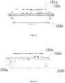
- the circuit board assembly 153 includes a circuit board 153a, a circuit board box 153b, and a sealing piece 153c.
- Both the first actuation element 151b and the second actuation element are installed on the circuit board 153a, the circuit board 153a is disposed in the accommodation space 11a surrounded by the base 11, the first actuation element 151b is disposed at least partially in the accommodation space 11a, and the second actuation element is disposed at least partially in the accommodation space 11a.
- the circuit board 153a is installed in the circuit board box 153b. When the circuit board 153a is disposed in the circuit board box 153b, sealant may be poured into the circuit board box 153b, which can improve the waterproof performance of the circuit board assembly 153.
- both the first actuation element 151b and the second actuation element are movably installed on the circuit board 153a, so the sealant cannot completely cover the first actuation element 151b and the second actuation element.
- the sealing piece 153c is disposed on an upper side of the whole formed by the circuit board 153a, the circuit board box 153b, the first actuation element 151b, and the second actuation element, and the sealing piece 153c may be a rubber piece. In this manner, the waterproof performance of the circuit board assembly 153 and the operation assembly 15 can be further improved.
- a misting fan 200 in embodiment two is provided. Compared with the misting fan 100 shown in FIG. 1 , the misting fan 200 in this embodiment has the same fan assembly 201, support assembly 202, and battery pack 203. A difference is that the misting fan 200 in this embodiment has another nozzle 20 with a structure different from the structure of the nozzle 14 in the misting fan 100 in FIG. 1 . In this embodiment, the structures other than the nozzle 20 of the misting fan 200 are the same as those in embodiment one. Hereinafter, only the structure of the nozzle 20 in this embodiment is specifically described.
- the nozzle 20 may be disposed on the fan assembly 201 or the support assembly 202. More specifically, the nozzle 20 is detachably installed on a fan cover 204.
- the nozzle 20 includes a nozzle body 21 and a nozzle head 22.
- the nozzle body 21 is configured to install the nozzle 20 to the support assembly 202 or the fan assembly 201.
- the nozzle head 22 is installed to the nozzle body 21 and the nozzle head 22 sprays water into the environment in a form of water mist.
- the nozzle body 21 includes a support piece 211 and a first part 212.
- the support piece 211 supports the first part 212
- the support piece 211 is formed with a first threaded portion 211a
- the main machine is formed with a fitting portion fitting with the first threaded portion 211a so that the support piece 211 may be detachably installed to the main machine through the first threaded portion 211a.
- the nozzle head 22 includes a second part 221 and a connection piece 222, where the connection piece 222 is configured to support the second part 221.
- the second part 221 is detachably installed to the nozzle body 21.
- the support piece 211 is formed with a second threaded portion 211b
- the connection piece 222 is formed with a second fitting portion 222a
- the whole formed by the connection piece 222 and the second part 221 is detachably installed to the support piece 211 of the nozzle body 21 through the second fitting portion 222a.
- the first part 212 is formed with a first surface 212a
- the second part 221 is formed with a second surface 221a.
- a water flow channel 223 through which water flows is formed between the second surface 221a and the first surface 212a. That is, the water flow channel 223 is disposed between the first surface 212a and the second surface 221a and sandwiched between the first surface 212a and the second surface 221a.
- the water flow channel 223 here may be a part of a channel in the nozzle 20 for water to flow through.
- a dimension of the water flow channel 223 may be less than dimensions of other parts of the channel, and of course, it is not limited to this.
- the second part 221 can be detached from the nozzle body 21.
- the second surface 221a is at least partially exposed to be cleaned.
- the dimension of the water flow channel 223 in the nozzle 20 is relatively small. After a long time of operation, scale, impurities, debris, and the like are likely to clog the water flow channel 223, which seriously affects the volume of water sprayed from the nozzle 20 and even causes the nozzle 20 to be unable to spray the water.
- the second part 221 can be detached from the nozzle body 21, and when the second part 221 is detached, the first surface 212a is exposed so that the user can conveniently clean the first surface 212a of the first part 212 and can also take out the debris trapped in the water flow channel 223, thereby not affecting the use of the nozzle 20.
- the use cost can be significantly reduced, and the nozzle 20 is prevented from being clogged so that the operation of the misting fan 200 is not affected, thereby improving the operation efficiency of the misting fan 200.
- the nozzle body 21 can be cleaned only by detaching the nozzle head 22, which is convenient and quick to operate.
- the second surface 221a is also at least partially exposed so that the user can also clean the second surface 221a on the nozzle head 22.
- a water inlet hole 211c is formed at an end of the support piece 211, an accommodation cavity 211d is formed in the support piece 211, the first part 212 is disposed in the accommodation cavity 211d, and the first part 212 is movably disposed in the accommodation cavity 211d.
- the first part 212 may also be fixedly disposed in the accommodation cavity 211d.
- the first surface 212a surrounds a centerline 200a
- the second surface 221a also surrounds the centerline 200a
- the second surface 221a is disposed on an outer side of the first surface 212a.
- a cross-section of the water flow channel 223 between the first surface 212a and the second surface 221a is annular.
- the second part 221 is formed with a water outlet hole 221b configured to spray the water into an external environment.
- the water outlet hole 221b is centered on the centerline 200a and disposed at an end of the second surface 221a.
- the second part 221 and the connection piece 222 are detachably connected so that the second part 221 can be replaced separately.
- a diameter of the water outlet hole 221b is greater than or equal to 0.2 mm and less than or equal to 0.4 mm.
- the nozzle body 21 further includes a spring 213 and an elastic piece 214.
- the spring 213 is supported between the elastic piece 214 and the first part 212.
- a hole 211e is formed on a bottom surface of the accommodation cavity 211d. The hole 211e communicates with the water inlet hole 211c.
- the elastic piece 214 is supported at the hole 211e. When the misting fan 200 stops operating, the elastic piece 214 can effectively prevent water in a waterway system from flowing out through the nozzle 20, thereby preventing the nozzle 20 from dripping water.
- the spring 213 presses the first part 212 toward the second part 221 so that it can be ensured that the dimension of the water flow channel 223 is small enough, which is conducive to the formation of water mist.
- the first surface 212a is at least partially an inclined surface
- the second surface 221a is also at least partially an inclined surface.
- a section line of the first surface 212a in a plane passing through the centerline 200a obliquely intersects with the centerline 200a
- a section line of the second surface 221a in the plane also obliquely intersects with the centerline 200a.
- the first surface 212a is a part of one conical surface
- the second surface 221a is a part of another conical surface.
- a first sealing ring 215 is connected to the nozzle body 21 and prevents water from flowing out of an outer wall of the nozzle 20 when the nozzle 20 is installed to the main machine.
- a notch 212b is formed at an end of the first part 212, and the notch 212b allows water to flow through to the water outlet hole 221b after the water flows through the water flow channel 223. In this manner, even if the first part 212 abuts against the second part 221 through the spring 213, the water can sequentially flow through the water flow channel 223, the notch 212b, and the water outlet hole 221b.
- a nozzle 300 in embodiment three is applicable to the misting fan 100 in FIG. 1 .
- the nozzle 300 has basically the same structure as the nozzle 20 in embodiment two, except that a nozzle head 32 and a nozzle body 31 are movably connected.
- a nozzle head 32 and a nozzle body 31 are movably connected.
- the nozzle head 32 and the nozzle body 31 are rotatably connected. It is to be understood that in other embodiments, the nozzle head and the nozzle body may be slidably connected.
- a second part 321 is movably installed to the nozzle body 31. When the second part 321 moves to a first position relative to a first part 312 in the nozzle body 31, a water flow channel 323 is formed between a second surface 321a and a first surface 312a. When the second part 321 moves to a second position relative to the first part 312, the first surface 312a is at least partially exposed to be cleaned.
- the movement of the second part 321 relative to the first part 312 may be understood as that the second part 321 can move relative to the first part 312 and may also be understood as that the second part 321 can rotate relative to the first part 312. In this manner, when the nozzle 300 is clogged, the user only needs to rotate the nozzle head 32 or move the nozzle head 32 to clean the water flow channel 323, which further improves the convenience of operation.
- the nozzle 400 includes a nozzle body 41 and a nozzle head 42.
- the nozzle body 41 includes a first part 411, a second part 412, and a spring 413.
- the first part 411 is formed with a first surface 411a
- the second part 412 is formed with a second surface 412a.
- a water flow channel 43 through which water flows may be formed between the first surface 411a and the second surface 412a.
- the nozzle head 42 is formed with a pressing portion 42a which can drive the second part 412 to move relative to the first part 411.
- the nozzle head 42 can move relative to the nozzle body 41 to an open position and a closed position.
- the pressing portion 42a presses the second part 412 to move to a first position relative to the first part 411.
- the water flow channel 43 is formed between the first surface 411a and the second surface 412a.
- the pressing portion 42a is detached from the second part 412, and the second part 412 can move to a second position under the action of the spring 413.
- the second surface 412a is at least partially exposed to be cleaned. It is to be understood that in other implementations, the first surface 411a may also be at least partially exposed to be cleaned.
Landscapes
- Engineering & Computer Science (AREA)
- Mechanical Engineering (AREA)
- General Engineering & Computer Science (AREA)
- Chemical & Material Sciences (AREA)
- Chemical Kinetics & Catalysis (AREA)
- Structures Of Non-Positive Displacement Pumps (AREA)
- Nozzles (AREA)
Abstract
Description
- This application claims priority to
Chinese Patent Application No. 202010336441.4 filed with the China National Intellectual Property Administration (CNIPA) on Apr. 26, 2020 Chinese Patent Application No. 202020655158.3 filed with the China National Intellectual Property Administration (CNIPA) on Apr. 26, 2020 Chinese Patent Application No. 202020656944.5 filed with the China National Intellectual Property Administration (CNIPA) on Apr. 26, 2020 - The present disclosure relates to a fan and, in particular, to a misting fan.
- The existing misting fan generally uses external mains electricity as a power source so that the misting fan can only be used where there is a socket, which reduces the convenience to use the misting fan and also limits the places where the misting fan can be used. Moreover, a nozzle on the existing misting fan is easily clogged and then needs to be replaced by a new nozzle, which increases the cost of use and also reduces operation efficiency. Especially when the misting fan is operating, if the nozzle is clogged and cannot be replaced in time, the misting fan cannot operate, either. Further, if the nozzle of the misting fan is not completely clogged, a user may not notice that the nozzle has a problem and will not replace the nozzle in time, thereby seriously affecting the cooling effect of the misting fan.
- To solve the defects in the existing art, an object of the present disclosure is to provide a misting fan that is convenient to carry and easy to clean.
- To achieve the preceding object, the present disclosure provides technical solutions described below.
- A misting fan includes a nozzle, a fan assembly, and a support assembly. The nozzle is configured to spray water. The fan assembly includes fan blades and an electric motor configured to drive the fan blades to rotate. The support assembly is configured to support the fan assembly. The support assembly is formed with a coupling portion for detachably coupling a battery pack. The nozzle is disposed on the fan assembly or the support assembly and includes a nozzle body and a second part. The nozzle body includes a first part formed with a first surface. The second part is detachably installed to the nozzle body and formed with a second surface. In the case where the second part is installed to the nozzle body, a water flow channel is formed between the second surface and the first surface; and in the case where the second part is detached from the nozzle body, the first surface is at least partially exposed to be cleaned.
- As an optional embodiment, the nozzle is detachably installed to the support assembly.
- As an optional embodiment, the fan assembly further includes a fan cover surrounding the fan blades, where the nozzle is detachably installed to the fan cover.
- As an optional embodiment, the nozzle body further includes a support piece configured to support the first part, where the first part and the support piece are detachably connected.
- As an optional embodiment, in the case where the second part is detached from the nozzle body, the second surface is at least partially exposed to be cleaned.
- As an optional embodiment, a connection piece is configured to detachably connect the second part to the nozzle body; the second part is formed with a water outlet hole through which the water is sprayed to an outside; and the second part and the connection piece are detachably connected.
- As an optional embodiment, the second part is formed with a water outlet hole through which the water is sprayed to an outside, where a diameter of the water outlet hole is greater than or equal to 0.2 mm and less than or equal to 0.4 mm.
- As an optional embodiment, the second part is formed with a water outlet hole through which the water is sprayed to an outside, where the water outlet hole has a centerline; where the first surface surrounds the centerline, and the second surface surrounds the centerline.
- As an optional embodiment, the nozzle body further includes a support piece configured to support the first part and formed with a water inlet hole and an accommodation cavity in which the first part is disposed.
- As an optional embodiment, the first part is movably disposed in the accommodation cavity.
- As an optional embodiment, the nozzle body further includes an elastic piece disposed in the accommodation cavity and a spring supported between the elastic piece and the first part; where the accommodation cavity is formed with a hole communicating with the water inlet hole on a bottom surface of the accommodation cavity, and the elastic piece is supported at the hole.
- As an optional embodiment, the nozzle has a water outlet hole centered on a centerline, where a section line of the first surface in a plane passing through the centerline obliquely intersects with the centerline, and a section line of the second surface in the plane also obliquely intersects with the centerline.
- As an optional embodiment, the first surface is a part of one conical surface and the second surface is a part of another conical surface.
- As an optional embodiment, the nozzle body further includes a support piece configured to support the first part, where the support piece is formed with a threaded portion configured to detachably install the nozzle to the fan assembly or the support assembly, and a sealing ring is disposed on the support piece.
- As an optional embodiment, the misting fan further includes the battery pack detachably installed to the coupling portion, a waterway system including a water pipe connected to the nozzle, and a pump connected to the water pipe; where output water pressure of the pump is greater than or equal to 40 psi and less than or equal to 120 psi.
- A misting fan includes a nozzle, a fan assembly, and a support assembly. The nozzle is configured to spray water. The fan assembly includes fan blades and an electric motor configured to drive the fan blades to rotate. The support assembly is configured to support the fan assembly. The support assembly is formed with a coupling portion for detachably coupling a battery pack. The nozzle is disposed on the fan assembly or the support assembly and includes a nozzle body and a second part. The nozzle body includes a first part formed with a first surface. The second part is movably installed to the nozzle body and formed with a second surface. In the case where the second part moves to a first position relative to the first part, a water flow channel is formed between the second surface and the first surface; and in the case where the second part moves to a second position relative to the first part, the first surface is at least partially exposed to be cleaned.
- A misting fan includes a nozzle, a fan assembly, and a support assembly. The nozzle is configured to spray water. The fan assembly includes fan blades and an electric motor configured to drive the fan blades to rotate. The support assembly is configured to support the fan assembly. The support assembly is formed with a coupling portion for detachably coupling a battery pack. The nozzle is disposed on the fan assembly or the support assembly and includes a first part and a second part. The first part is formed with a first surface. The second part is movable relative to the first part and formed with a second surface. In the case where the second part moves to a first position relative to the first part, a water flow channel is formed between the second surface and the first surface; and in the case where the second part moves to a second position relative to the first part, the first surface or the second surface is at least partially exposed to be cleaned.
- As an optional embodiment, the second part is formed with a water outlet hole through which the water is sprayed to an outside, where a diameter of the water outlet hole is greater than or equal to 0.2 mm and less than or equal to 0.4 mm.
- As an optional embodiment, the second part is formed with the water outlet hole through which the water is sprayed to the outside, and the water outlet hole has a centerline; where the first surface surrounds the centerline and the second surface surrounds the centerline.
- As an optional embodiment, the first surface is a part of one conical surface and the second surface is a part of another conical surface.
- The present disclosure has the following beneficial effects: the misting fan is more convenient to use, more widely used, and convenient for a user to clean.
-
-
FIG. 1 is a plan view of a misting fan according to embodiment one; -
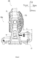
FIG. 2 is a side view of the misting fan ofFIG. 1 ; -
FIG. 3 is a perspective view of the misting fan ofFIG. 1 ; -
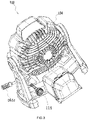
FIG. 4 is a perspective view of the misting fan ofFIG. 1 with a first battery pack detached; -
FIG. 5 is a perspective view of a main machine of the misting fan ofFIG. 1 ; -
FIG. 6 is a perspective view of the main machine ofFIG. 5 from another angle; -
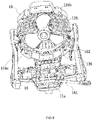
FIG. 7 is a perspective view of the misting fan ofFIG. 1 with nozzles detached; -
FIG. 8 is a perspective view of the misting fan ofFIG. 1 with a base opened; -
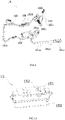
FIG. 9 is a perspective view of a waterway system ofFIG. 8 ; -
FIG. 10 is a perspective view of an operation assembly ofFIG. 8 ; -
FIG. 11 is a plan view of the operation assembly ofFIG. 10 ; -
FIG. 12 is a sectional view of the operation assembly ofFIG. 10 ; -
FIG. 13 is a plan view of a misting fan according to embodiment two; -
FIG. 14 is a perspective view of a nozzle of the misting fan ofFIG. 13 ; -
FIG. 15 is a sectional view of the nozzle ofFIG. 14 ; -
FIG. 16 is a perspective view of the nozzle ofFIG. 14 with a nozzle head separated from a nozzle body; -
FIG. 17 is a sectional view of the nozzle ofFIG. 14 with a nozzle head separated from a nozzle body; -
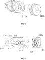
FIG. 18 is an exploded view of the nozzle ofFIG. 14 ; -
FIG. 19 is another exploded view of the nozzle ofFIG. 14 ; -
FIG. 20 is an enlarged view of a first part ofFIG. 18 ; -
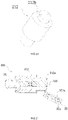
FIG. 21 is a sectional view of a nozzle according to embodiment three; -
FIG. 22 is a sectional view of a nozzle according to embodiment four, where a nozzle head is at a closed position; and -
FIG. 23 is a sectional view of the nozzle ofFIG. 22 when the nozzle head is at an open position. - A misting
fan 100 shown inFIG. 1 in embodiment one is configured to spray water. The water sprayed into air can cool the environment. The mistingfan 100 may be applied to outdoor places such as a basketball court, a park, and a playground. When used outdoors, the mistingfan 100 may use water in a bucket. The mistingfan 100 may also be applied to indoor places such as a shopping mall, a factory, and a warehouse. When used indoors, the mistingfan 100 may be connected to a tap water pipe. - As shown in
FIGS. 1 to 4 , the mistingfan 100 includes amain machine 10 and afirst battery pack 101, where thefirst battery pack 101 may be detachably installed to themain machine 10. In this manner, the mistingfan 100 can be conveniently carried outdoors for operation. The mistingfan 100 with thefirst battery pack 101 is more convenient to use especially in places where there is no convenient power source such as the park. - The
main machine 10 includes asupport assembly 10a, afan assembly 13, and anozzle 14. Thesupport assembly 10a is configured to support thefan assembly 13 and thenozzle 14, and thesupport assembly 10a includes abase 11 and asupport arm 12. Thebase 11 is configured to support the entire mistingfan 100 so that the mistingfan 100 is placed on a workbench. Thesupport arm 12 is connected to thebase 11 and disposed at least partially above thebase 11. An end of thesupport arm 12 is connected to thebase 11, and the other end of thesupport arm 12 is connected to thefan assembly 13 so that thesupport arm 12 supports thefan assembly 13. Thefan assembly 13 includesfan blades 131 and anelectric motor 132, where theelectric motor 132 is configured to drive thefan blades 131 to rotate around anelectric motor axis 100a. Thenozzle 14 is configured to spray the water and installed to thesupport assembly 10a or thefan assembly 13. When thefirst battery pack 101 is installed to themain machine 10, the mistingfan 100 is started, the water is sprayed from thenozzle 14 into an external environment, and thefan blades 131 rotate to generate an airflow to blow the water sprayed from thenozzle 14 into the air so that the temperature of the air in the environment drops. - The
first battery pack 101 is detachably installed to thesupport assembly 10a. In this embodiment, thefirst battery pack 101 is installed to thebase 11. It is to be understood that, in other embodiments, thefirst battery pack 101 may also be installed to thesupport arm 12. It is to be understood that all parts other than thefan blades 131 and theelectric motor 132 driving thefan blades 131 to rotate in the mistingfan 100 may be considered to belong to thesupport assembly 10a. In this manner, thefirst battery pack 101 may be installed to any part of thesupport assembly 10a. - As shown in
FIGS. 4 to 6 , thebase 11 is formed with acoupling portion 111 for coupling thefirst battery pack 101. Thecoupling portion 111 surrounds and forms abattery compartment 111a, where thefirst battery pack 101 is capable of being installed in thebattery compartment 111a. In this embodiment, asecond battery pack 102 is also capable of being installed in thebattery compartment 111a. Thefirst battery pack 101 has a first volume and a first capacity, and thesecond battery pack 102 has a second volume and a second capacity. The first volume is greater than the second volume, and the first capacity is greater than the second capacity. Thesupport assembly 10a further includes abattery cover 112, and thefirst battery pack 101 is connected to thecoupling portion 111. Thebattery cover 112 has an open state and a closed state relative to thecoupling portion 111. When thebattery cover 112 is in the open state, thebattery cover 112 allows thefirst battery pack 101 or thesecond battery pack 102 to be detached from thebattery compartment 111a. When thebattery cover 112 is in the closed state, thebattery cover 112 and thecoupling portion 111 jointly surround and form anaccommodation cavity 113 for accommodating thefirst battery pack 101 or thesecond battery pack 102, and at this time, thebattery cover 112 covers thebattery compartment 111a. Anaccess terminal 111b is disposed in thebattery compartment 111a and electrically connected to thefirst battery pack 101 or thesecond battery pack 102. When thebattery cover 112 is in the open state, thefirst battery pack 101 is capable of being inserted into thebattery compartment 111a, and thesecond battery pack 102 is also capable of being inserted into thebattery compartment 111a. A user can selectively insert thefirst battery pack 101 or thesecond battery pack 102 into thebattery compartment 111a according to requirements. Thebattery compartment 111a can fit with not only thefirst battery pack 101 but also thesecond battery pack 102. Therefore, the user can install battery packs with different volumes or different capacities according to requirements, which improves the adaptability of the mistingfan 100 and prolongs the lifetime of the mistingfan 100. When thebattery cover 112 is in the closed state, thebattery cover 112 and thecoupling portion 111 surround and form theaccommodation cavity 113, and theaccommodation cavity 113 can accommodate not only thefirst battery pack 101 but also thesecond battery pack 102. In this manner, the user can select and install a battery pack with a larger volume or a larger capacity to the mistingfan 100. - In this embodiment, the
first battery pack 101 and thesecond battery pack 102 have the same nominal voltage, a nominal voltage of thefirst battery pack 101 is greater than or equal to 20V, and a nominal voltage of thesecond battery pack 102 is greater than or equal to 20V. Further, the nominal voltage of thefirst battery pack 101 is greater than or equal to 40V, and the nominal voltage of thesecond battery pack 102 is greater than or equal to 40V so that thefirst battery pack 101 or thesecond battery pack 102 outputs greater power and has a greater capacity, thereby improving the operation time and efficiency of the mistingfan 100. - Of course, it is to be understood that the
battery compartment 111a of themain machine 10 may also be adapted to athird battery pack 103, and thethird battery pack 103 may have a third volume and a third capacity, thereby further improving the adaptability of the mistingfan 100. - The
support arm 12 supports thefan assembly 13 on an upper side of thebase 11, and thefan assembly 13 can rotate relative to thesupport arm 12. Thecoupling portion 111 is disposed on a lower side of thefan assembly 13. When installed in thebattery compartment 111a, thefirst battery pack 101 is located on the lower side of thefan assembly 13. In this manner, thecoupling portion 111 does not interfere with the rotation of thefan assembly 13 and does not affect an air inlet region on a rear side of thefan assembly 13, thereby improving blowing efficiency. In this embodiment, both thefirst battery pack 101 and thesecond battery pack 102 can be installed in thebattery compartment 111a. Due to a relatively large volume of thefirst battery pack 101, a relatively large volume is provided in thebattery compartment 111a. Therefore, in this embodiment, thefirst battery pack 101 is inserted into thebattery compartment 111a along a direction of a firststraight line 100b, that is, thecoupling portion 111 is formed with aguide structure 111c guiding thefirst battery pack 101 or thesecond battery pack 102 to be coupled to thebattery compartment 111a along the direction of the firststraight line 100b. When the mistingfan 100 is placed on a plane, the firststraight line 100b obliquely intersects with the plane. In this manner, on one hand, in the case where a position of thefan assembly 13 in an up-and-down direction perpendicular to the plane is not too high, thecoupling portion 111 can be prevented from shielding the air inlet region of thefan assembly 13 as much as possible. On the other hand, the volume in thebattery compartment 111a can be increased so that the battery pack with the larger volume or the larger capacity can be installed to the mistingfan 100. - In this embodiment, when the misting
fan 100 is placed on the plane, the firststraight line 100b intersects with the plane so as to form an angle greater than 0 degrees and less than or equal to 30 degrees. A height of thebattery compartment 111a in the up-and-down direction is greater than or equal to 60 mm and less than or equal to 100 mm. In this manner, the volume in thebattery compartment 111a is large enough so that thebattery compartment 111a can be adapted to the battery pack with the larger volume. - In a front-and-rear direction, the
battery compartment 111a is disposed at least partially on the rear side of thefan assembly 13 so that anoperation assembly 15 shown inFIG. 7 can be disposed in a region of the base 11 on a front side of thefan assembly 13. When thebattery cover 112 is in the open state, thebattery compartment 111a is open backwards, and thefirst battery pack 101 or thesecond battery pack 102 is inserted into thebattery compartment 111a from a rear side of themain machine 10. - The
battery cover 112 is rotatably connected to thecoupling portion 111 around afirst axis 100c. When the mistingfan 100 is disposed on a plane, thefirst axis 100c is parallel to the plane. When the mistingfan 100 is disposed on the plane, the user can open thebattery cover 112 backwards so that thebattery cover 112 is in the open state, and at this time, an outer surface of thebattery cover 112 can be supported on the plane and the user does not need to hold thebattery cover 112 with one hand and can conveniently detach thefirst battery pack 101 or thesecond battery pack 102, which improves the convenience of operation. Thebattery cover 112 is disposed on a rear side of thecoupling portion 111, and theguide structure 111c guides thefirst battery pack 101 to be inserted into thebattery compartment 111a in a direction oblique relative to the plane so that a region on the rear side of thecoupling portion 111 is enough for thebattery cover 112 to be opened. In this manner, when the mistingfan 100 is placed on the plane, an angle through which thebattery cover 112 rotates from a closed position to an open position is greater than 90 degrees. Therefore, when thebattery cover 112 rotates to the open position, more space is reserved on an upper side of thebattery cover 112 to allow thefirst battery pack 101 or thesecond battery pack 102 to be detached from thebattery compartment 111a. Further, the problem that when the mistingfan 100 is placed on the plane, thebattery cover 112 cannot be opened backwards to the open position to allow thefirst battery pack 101 to be detached from thebattery compartment 111a can be avoided, that is, the problem that thebattery cover 112 cannot be completely opened can be avoided. - A
water leakage hole 111d is disposed on a bottom surface of thebattery compartment 111a. When entering thebattery compartment 111a, water can flow out of thebattery compartment 111a through thewater leakage hole 111d. - When the
fan assembly 13 is in an upright state as shown inFIG. 2 and thebattery cover 112 is in the closed state, a part of the whole formed by thecoupling portion 111 and thebattery cover 112 that is disposed on the rear side of thefan assembly 13 has a dimension L in the front-and-rear direction, where the dimension L is greater than or equal to 60 mm and less than or equal to 100 mm so that the volume in thebattery compartment 111a can be increased. - In this embodiment, a ratio of the first capacity of the
first battery pack 101 to the second capacity of thesecond battery pack 102 is greater than or equal to 2. Alternatively, in other embodiments, the ratio of the first capacity of thefirst battery pack 101 to the second capacity of thesecond battery pack 102 is greater than or equal to 3. - The first capacity of the
first battery pack 101 is also greater than 4.5 AH, thereby increasing the lifetime of thefirst battery pack 101 and increasing the operation duration of the mistingfan 100. More specifically, thefirst battery pack 101 may include a first cell group and a second cell group, where multiple cell units in the first cell group are connected in series. Multiple cell units may also be disposed in the second cell group. The first cell group and the second cell group are connected in parallel. That is, two cell groups connected in parallel are disposed in thefirst battery pack 101. Of course, it is to be understood that in other embodiments, three cell groups connected in parallel may be disposed in thefirst battery pack 101, thereby further increasing the lifetime of thefirst battery pack 101. The first capacity of thefirst battery pack 101 may also be greater than or equal to 5 AH. - As shown in
FIGS. 7 and8 , twonozzles 14 are provided, and twoinstallation pieces 133 are connected on an outer side of thefan assembly 13. The twoinstallation pieces 133 are respectively disposed on two sides of thefan assembly 13. Thenozzle 14 is installed to theinstallation piece 133, and the whole formed by thenozzle 14 and theinstallation piece 133 can rotate with thefan assembly 13. Thenozzle 14 is detachably installed to theinstallation piece 133. In this manner, when a water flow channel or a water outlet hole in thenozzle 14 is clogged by scale or debris, the user can conveniently detach thenozzle 14 to replace thenozzle 14 with a new one. - As shown in
FIGS. 8 and9 , themain machine 10 further includes awaterway system 16 configured to deliver external water to thenozzle 14. Thewaterway system 16 includes a firstwater pipe assembly 161 and a secondwater pipe assembly 162. The firstwater pipe assembly 161 is configured to deliver external water from a first external water source to thenozzle 14. The first external water source may specifically be a static water source. The static water source may be understood as water contained in a storage such as the bucket. The secondwater pipe assembly 162 is configured to deliver external water from a second external water source to thenozzle 14. The second external water source is specifically a flowing water source. The flowing water source may be understood as a water source with a certain flowrate such as tap water. When used in a place with the flowing water source, the mistingfan 100 may use the flowing water source so that the mistingfan 100 can operate for a relatively long time without replacing the water source. When used in a place where there is no flowing water source, the mistingfan 100 may use the water in the storage, thereby improving the convenience to use the mistingfan 100. - Specifically, the first
water pipe assembly 161 includes afirst water pipe 161a, athird water pipe 161b, and afirst connection piece 161c. The mistingfan 100 further includes apump 163 installed to the firstwater pipe assembly 161. Thefirst water pipe 161a includes afirst end 161d and athird end 161e. Thefirst connection piece 161c is installed to thefirst end 161d of thefirst water pipe 161a, and thefirst connection piece 161c is configured to be connected to the first external water source. Thesecond end 161c of thefirst water pipe 161a is connected to an input end of thepump 163, and thethird water pipe 161b is connected to an output end of thepump 163. Thepump 163 pumps the water in the storage into thefirst water pipe 161a and then outputs the water to thethird water pipe 161b. - The base 11 surrounds and forms an
accommodation space 11a, and thepump 163 is disposed in theaccommodation space 11a. Thebattery compartment 111a is also formed by thebase 11. In this embodiment, theaccommodation space 11a and thebattery compartment 111a are disposed separately so that water vapor can be prevented from entering thebattery compartment 111a. - The second
water pipe assembly 162 includes asecond water pipe 162a and asecond connection piece 162b, and thesecond connection piece 162b is configured to be connected to the second external water source. Thesecond water pipe 162a includes asecond end 162c and afourth end 162d, and thesecond connection piece 162b is installed to thesecond end 162c of thesecond water pipe 162a. - In this embodiment, a part of the first
water pipe assembly 161 is disposed in thebase 11 and a part of the firstwater pipe assembly 161 is disposed in thefan assembly 13. The secondwater pipe assembly 162 is disposed outside thebase 11. In this manner, the secondwater pipe assembly 162 does not pass through an inside of the base 11 so that a length of the secondwater pipe assembly 162 can be shortened, and the secondwater pipe assembly 162 can easily adapt to the rotation of thefan assembly 13. In this embodiment, a part of the secondwater pipe assembly 162 is disposed in thefan assembly 13, another part of the secondwater pipe assembly 162 is disposed outside thefan assembly 13, and the part of the secondwater pipe assembly 162 outside thefan assembly 13 is exposed so that it is convenient for the user to connect the secondwater pipe assembly 162 to the flowing water source. - The
fan assembly 13 further includes afan cover 134 configured to surround thefan blades 131, and theelectric motor 132 is also disposed in thefan cover 134. Theinstallation piece 133 may be considered as a part of thefan cover 134 and may also be integrally formed with thefan cover 134. Thenozzle 14 is disposed on theinstallation piece 133, which may also be understood as that thenozzle 14 is installed to thefan cover 134. Thefan cover 134 further includes afront fan cover 134a and arear fan cover 134b. When thefront fan cover 134a is docked with therear fan cover 134b, thefront fan cover 134a and therear fan cover 134b surround and form afirst accommodation cavity 135 for accommodating a fan and theelectric motor 132. A part of thesecond water pipe 162a extends into thefan cover 134, that is, a part of thesecond water pipe 162a is disposed in thefirst accommodation cavity 135, and thesecond water pipe 162a extends from an inside of thefan cover 134 to an outside of thefan cover 134. A part of thesecond water pipe 162a outside thefan cover 134 passes through neither thesupport arm 12 nor the base 11 so that the part of thesecond water pipe 162a outside thefan cover 134 is exposed. The part of thesecond water pipe 162a outside thefan cover 134 is exposed, which does not limit a protective sleeve to be sleeved on an outer wall of thesecond water pipe 134. Even if the protective sleeve is sleeved on thesecond water pipe 134, it is considered that thesecond water pipe 134 is exposed. - A limiting
piece 114 is disposed on an outer surface of thebase 11 and configured to be in contact with thesecond water pipe 162a to limit a position of thesecond water pipe 162a. - A first groove extending in a circumferential direction around the
electric motor axis 100a is formed at an edge of thefront fan cover 134a, and asecond groove 134c extending in the circumferential direction around theelectric motor axis 100a is formed at an edge of therear fan cover 134b. When thefront fan cover 134a is docked with therear fan cover 134b, the first groove is docked with thesecond groove 134c to form asecond accommodation cavity 136 for accommodating part of thewaterway system 16. - The
waterway system 16 further includes afourth water pipe 164, afifth water pipe 165, and adistribution element 166. Thedistribution element 166 is separately connected to the firstwater pipe assembly 161 and the secondwater pipe assembly 162 and configured to distribute water delivered from the firstwater pipe assembly 161 or the secondwater pipe assembly 162 to thefourth water pipe 164 and thefifth water pipe 165 and then deliver water to thenozzles 14 through thefourth water pipe 164 and thefifth water pipe 165. Thedistribution element 166 is installed to thefan assembly 13. Specifically, thedistribution element 166 is disposed in thefan cover 134 and disposed in thesecond accommodation cavity 136, thesecond water pipe 162a extends into thesecond accommodation cavity 136 and is connected to thedistribution element 166, and thethird water pipe 161b also extends into thesecond accommodation cavity 136 and is connected to thedistribution element 166 so that both thesecond water pipe 162a and thethird water pipe 161b can deliver water to thedistribution element 166. Thedistribution element 166 is also connected to thefourth water pipe 164 and thefifth water pipe 165. Thefourth water pipe 164 is disposed partially in thesecond accommodation cavity 136, and thefifth water pipe 165 is disposed partially in thesecond accommodation cavity 136. An end of thefourth water pipe 164 is connected to thedistribution element 166, and the other end of thefourth water pipe 164 is connected to onenozzle 14. An end of thefifth water pipe 165 is connected to thedistribution element 166, and the other end of thefifth water pipe 165 is connected to anothernozzle 14. In this manner, thewaterway system 16 can be set more reasonably and has higher efficiency. - In this embodiment, the
pump 163 may be adiaphragm pump 163 or apiston pump 163. Output water pressure of thepump 163 is greater than or equal to 40 psi and less than or equal to 120 psi. An output rotation speed of thepump 163 is greater than or equal to 500 rpm and less than or equal to 900 rpm. In this manner, while it is ensured that a flowrate of the water sprayed from thenozzle 14 is sufficiently large, the flowrate of the water can be made more stable. Further, the output water pressure of thepump 163 is greater than or equal to 45 psi and less than or equal to 75 psi, and the output rotation speed of thepump 163 is greater than or equal to 500 rpm, which ensures that the operation duration of thefirst battery pack 101 or thesecond battery pack 102 can satisfy requirements of the user. - As shown in
FIGS. 10 to 12 , theoperation assembly 15 includes afirst adjustment piece 151 and asecond adjustment piece 152. Thefirst adjustment piece 151 is configured to adjust a volume of the water sprayed from thenozzle 14 so that the user can select the volume of the water according to humidity in the environment. Thesecond adjustment piece 152 is configured for the user to adjust a rotation speed of the fan so that the user can select a wind speed according to the humidity in the environment. The mistingfan 100 further includes acircuit board assembly 153 configured to control thepump 163 and theelectric motor 132. - The
first adjustment piece 151 includes a firstthin film 151a and afirst actuation element 151b. Thesecond adjustment piece 152 includes a second actuation element. The firstthin film 151a is disposed on an outer surface of thesupport assembly 10a, thefirst actuation element 151b is disposed at least partially in thesupport assembly 10a, and the second actuation element is disposed in thesupport assembly 10a. The firstthin film 151a is disposed on an upper surface of thebase 11. Thecircuit board assembly 153 includes acircuit board 153a, acircuit board box 153b, and asealing piece 153c. Both thefirst actuation element 151b and the second actuation element are installed on thecircuit board 153a, thecircuit board 153a is disposed in theaccommodation space 11a surrounded by thebase 11, thefirst actuation element 151b is disposed at least partially in theaccommodation space 11a, and the second actuation element is disposed at least partially in theaccommodation space 11a. Thecircuit board 153a is installed in thecircuit board box 153b. When thecircuit board 153a is disposed in thecircuit board box 153b, sealant may be poured into thecircuit board box 153b, which can improve the waterproof performance of thecircuit board assembly 153. However, both thefirst actuation element 151b and the second actuation element are movably installed on thecircuit board 153a, so the sealant cannot completely cover thefirst actuation element 151b and the second actuation element. In this embodiment, the sealingpiece 153c is disposed on an upper side of the whole formed by thecircuit board 153a, thecircuit board box 153b, thefirst actuation element 151b, and the second actuation element, and thesealing piece 153c may be a rubber piece. In this manner, the waterproof performance of thecircuit board assembly 153 and theoperation assembly 15 can be further improved. - As shown in
FIG. 13 , a mistingfan 200 in embodiment two is provided. Compared with the mistingfan 100 shown inFIG. 1 , the mistingfan 200 in this embodiment has thesame fan assembly 201,support assembly 202, andbattery pack 203. A difference is that the mistingfan 200 in this embodiment has anothernozzle 20 with a structure different from the structure of thenozzle 14 in the mistingfan 100 inFIG. 1 . In this embodiment, the structures other than thenozzle 20 of the mistingfan 200 are the same as those in embodiment one. Hereinafter, only the structure of thenozzle 20 in this embodiment is specifically described. - In this embodiment, the
nozzle 20 may be disposed on thefan assembly 201 or thesupport assembly 202. More specifically, thenozzle 20 is detachably installed on afan cover 204. - As shown in
FIGS. 13 and14 , in this embodiment, thenozzle 20 includes anozzle body 21 and anozzle head 22. Thenozzle body 21 is configured to install thenozzle 20 to thesupport assembly 202 or thefan assembly 201. Thenozzle head 22 is installed to thenozzle body 21 and thenozzle head 22 sprays water into the environment in a form of water mist. - As shown in
FIGS. 14 to 19 , in this embodiment, thenozzle body 21 includes asupport piece 211 and afirst part 212. Thesupport piece 211 supports thefirst part 212, thesupport piece 211 is formed with a first threadedportion 211a, and the main machine is formed with a fitting portion fitting with the first threadedportion 211a so that thesupport piece 211 may be detachably installed to the main machine through the first threadedportion 211a. - The
nozzle head 22 includes asecond part 221 and aconnection piece 222, where theconnection piece 222 is configured to support thesecond part 221. In this embodiment, thesecond part 221 is detachably installed to thenozzle body 21. Specifically, thesupport piece 211 is formed with a second threadedportion 211b, theconnection piece 222 is formed with a secondfitting portion 222a, and the whole formed by theconnection piece 222 and thesecond part 221 is detachably installed to thesupport piece 211 of thenozzle body 21 through the secondfitting portion 222a. - The
first part 212 is formed with afirst surface 212a, and thesecond part 221 is formed with asecond surface 221a. When thesecond part 221 is installed to thenozzle body 21 through theconnection piece 222, awater flow channel 223 through which water flows is formed between thesecond surface 221a and thefirst surface 212a. That is, thewater flow channel 223 is disposed between thefirst surface 212a and thesecond surface 221a and sandwiched between thefirst surface 212a and thesecond surface 221a. Of course, it is to be understood that thewater flow channel 223 here may be a part of a channel in thenozzle 20 for water to flow through. A dimension of thewater flow channel 223 may be less than dimensions of other parts of the channel, and of course, it is not limited to this. - In this embodiment, the
second part 221 can be detached from thenozzle body 21. When thesecond part 221 is detached from thenozzle body 21, thesecond surface 221a is at least partially exposed to be cleaned. The dimension of thewater flow channel 223 in thenozzle 20 is relatively small. After a long time of operation, scale, impurities, debris, and the like are likely to clog thewater flow channel 223, which seriously affects the volume of water sprayed from thenozzle 20 and even causes thenozzle 20 to be unable to spray the water. In this embodiment, thesecond part 221 can be detached from thenozzle body 21, and when thesecond part 221 is detached, thefirst surface 212a is exposed so that the user can conveniently clean thefirst surface 212a of thefirst part 212 and can also take out the debris trapped in thewater flow channel 223, thereby not affecting the use of thenozzle 20. On one hand, the use cost can be significantly reduced, and thenozzle 20 is prevented from being clogged so that the operation of the mistingfan 200 is not affected, thereby improving the operation efficiency of the mistingfan 200. In addition, thenozzle body 21 can be cleaned only by detaching thenozzle head 22, which is convenient and quick to operate. - In this embodiment, when the
nozzle head 22 is detached from thenozzle body 21, thesecond surface 221a is also at least partially exposed so that the user can also clean thesecond surface 221a on thenozzle head 22. - Specifically, a
water inlet hole 211c is formed at an end of thesupport piece 211, anaccommodation cavity 211d is formed in thesupport piece 211, thefirst part 212 is disposed in theaccommodation cavity 211d, and thefirst part 212 is movably disposed in theaccommodation cavity 211d. Of course, in other implementations, thefirst part 212 may also be fixedly disposed in theaccommodation cavity 211d. Thefirst surface 212a surrounds acenterline 200a, thesecond surface 221a also surrounds thecenterline 200a, and thesecond surface 221a is disposed on an outer side of thefirst surface 212a. In a plane perpendicular to thecenterline 200a, a cross-section of thewater flow channel 223 between thefirst surface 212a and thesecond surface 221a is annular. - The
second part 221 is formed with awater outlet hole 221b configured to spray the water into an external environment. Thewater outlet hole 221b is centered on thecenterline 200a and disposed at an end of thesecond surface 221a. Thesecond part 221 and theconnection piece 222 are detachably connected so that thesecond part 221 can be replaced separately. A diameter of thewater outlet hole 221b is greater than or equal to 0.2 mm and less than or equal to 0.4 mm. - The
nozzle body 21 further includes aspring 213 and anelastic piece 214. Thespring 213 is supported between theelastic piece 214 and thefirst part 212. Ahole 211e is formed on a bottom surface of theaccommodation cavity 211d. Thehole 211e communicates with thewater inlet hole 211c. Theelastic piece 214 is supported at thehole 211e. When the mistingfan 200 stops operating, theelastic piece 214 can effectively prevent water in a waterway system from flowing out through thenozzle 20, thereby preventing thenozzle 20 from dripping water. Thespring 213 presses thefirst part 212 toward thesecond part 221 so that it can be ensured that the dimension of thewater flow channel 223 is small enough, which is conducive to the formation of water mist. - The
first surface 212a is at least partially an inclined surface, and thesecond surface 221a is also at least partially an inclined surface. A section line of thefirst surface 212a in a plane passing through thecenterline 200a obliquely intersects with thecenterline 200a, and a section line of thesecond surface 221a in the plane also obliquely intersects with thecenterline 200a. Alternatively, it is to be understood that thefirst surface 212a is a part of one conical surface, and thesecond surface 221a is a part of another conical surface. - A
first sealing ring 215 is connected to thenozzle body 21 and prevents water from flowing out of an outer wall of thenozzle 20 when thenozzle 20 is installed to the main machine. - In this embodiment, as shown in
FIG. 20 , anotch 212b is formed at an end of thefirst part 212, and thenotch 212b allows water to flow through to thewater outlet hole 221b after the water flows through thewater flow channel 223. In this manner, even if thefirst part 212 abuts against thesecond part 221 through thespring 213, the water can sequentially flow through thewater flow channel 223, thenotch 212b, and thewater outlet hole 221b. - A
nozzle 300 in embodiment three, as shown inFIG. 21 , is applicable to the mistingfan 100 inFIG. 1 . Thenozzle 300 has basically the same structure as thenozzle 20 in embodiment two, except that anozzle head 32 and anozzle body 31 are movably connected. Hereinafter, only the structural differences between thenozzle 300 in this embodiment and thenozzle 20 in embodiment two are described. - In this embodiment, the
nozzle head 32 and thenozzle body 31 are rotatably connected. It is to be understood that in other embodiments, the nozzle head and the nozzle body may be slidably connected. In this manner, asecond part 321 is movably installed to thenozzle body 31. When thesecond part 321 moves to a first position relative to afirst part 312 in thenozzle body 31, awater flow channel 323 is formed between asecond surface 321a and afirst surface 312a. When thesecond part 321 moves to a second position relative to thefirst part 312, thefirst surface 312a is at least partially exposed to be cleaned. The movement of thesecond part 321 relative to thefirst part 312 may be understood as that thesecond part 321 can move relative to thefirst part 312 and may also be understood as that thesecond part 321 can rotate relative to thefirst part 312. In this manner, when thenozzle 300 is clogged, the user only needs to rotate thenozzle head 32 or move thenozzle head 32 to clean thewater flow channel 323, which further improves the convenience of operation. - A
nozzle 400 in embodiment four, as shown inFIGS. 22 and 23 , is applicable to the mistingfan 100 inFIG. 1 . Thenozzle 400 includes anozzle body 41 and anozzle head 42. In this embodiment, thenozzle body 41 includes afirst part 411, asecond part 412, and aspring 413. Thefirst part 411 is formed with afirst surface 411a, and thesecond part 412 is formed with asecond surface 412a. Awater flow channel 43 through which water flows may be formed between thefirst surface 411a and thesecond surface 412a. Thenozzle head 42 is formed with apressing portion 42a which can drive thesecond part 412 to move relative to thefirst part 411. Thenozzle head 42 can move relative to thenozzle body 41 to an open position and a closed position. When thenozzle head 42 is at the closed position, thepressing portion 42a presses thesecond part 412 to move to a first position relative to thefirst part 411. At this time, thewater flow channel 43 is formed between thefirst surface 411a and thesecond surface 412a. When thenozzle head 42 is at the open position, thepressing portion 42a is detached from thesecond part 412, and thesecond part 412 can move to a second position under the action of thespring 413. At this time, thesecond surface 412a is at least partially exposed to be cleaned. It is to be understood that in other implementations, thefirst surface 411a may also be at least partially exposed to be cleaned. - The above illustrates and describes basic principles, main features, and advantages of the present disclosure. It is to be understood by those skilled in the art that the preceding embodiments do not limit the present disclosure in any form, and technical solutions obtained by means of equivalent substitution or equivalent transformation fall within the scope of the present disclosure.
Claims (20)
- A misting fan, comprising:a nozzle configured to spray water;a fan assembly comprising fan blades and an electric motor configured to drive the fan blades to rotate; anda support assembly configured to support the fan assembly;wherein the support assembly is formed with a coupling portion for detachably coupling a battery pack, the nozzle is disposed on the fan assembly or the support assembly, and the nozzle comprises:a nozzle body comprising a first part formed with a first surface; anda second part detachably installed to the nozzle body and formed with a second surface;wherein a water flow channel is formed between the second surface and the first surface when the second part is installed to the nozzle body, and the first surface is at least partially exposed to be cleaned when the second part is detached from the nozzle body.
- The misting fan of claim 1, wherein the nozzle is detachably installed to the support assembly.
- The misting fan of claim 1, wherein the fan assembly further comprises a fan cover surrounding the fan blades, and the nozzle is detachably installed to the fan cover.
- The misting fan of claim 1, wherein the nozzle body further comprises a support piece configured to support the first part, and the first part and the support piece are detachably connected.
- The misting fan of claim 1, wherein when the second part is detached from the nozzle body, the second surface is at least partially exposed to be cleaned.
- The misting fan of claim 1, whereina connection piece is configured to detachably connect the second part to the nozzle body; andthe second part is formed with a water outlet hole through which the water is sprayed to an outside; and the second part and the connection piece are detachably connected.
- The misting fan of claim 1, wherein the second part is formed with a water outlet hole through which the water is sprayed to an outside, and a diameter of the water outlet hole is greater than or equal to 0.2 mm and less than or equal to 0.4 mm.
- The misting fan of claim 1, wherein the second part is formed with a water outlet hole through which the water is sprayed to an outside, the water outlet hole has a centerline, the first surface surrounds the centerline, and the second surface surrounds the centerline.
- The misting fan of claim 1, wherein the nozzle body further comprises a support piece configured to support the first part, and the support piece is formed with a water inlet hole and an accommodation cavity in which the first part is disposed.
- The misting fan of claim 9, wherein the first part is movably disposed in the accommodation cavity.
- The misting fan of claim 10, wherein the nozzle body further comprises an elastic piece disposed in the accommodation cavity and a spring supported between the elastic piece and the first part, the accommodation cavity is formed with a hole communicating with the water inlet hole on a bottom surface of the accommodation cavity, and the elastic piece is supported at the hole.
- The misting fan of claim 1, wherein the nozzle has a water outlet hole centered on a centerline, a section line of the first surface in a plane passing through the centerline obliquely intersects with the centerline, and a section line of the second surface in the plane also obliquely intersects with the centerline.
- The misting fan of claim 1, wherein the first surface is a part of one conical surface and the second surface is a part of another conical surface.
- The misting fan of claim 1, wherein the nozzle body further comprises a support piece configured to support the first part, the support piece is formed with a threaded portion configured to detachably install the nozzle to the fan assembly or the support assembly, and a sealing ring is disposed on the support piece.
- The misting fan of claim 1, further comprising:the battery pack detachably installed to the coupling portion;a waterway system comprising a water pipe connected to the nozzle; anda pump connected to the water pipe;wherein output water pressure of the pump is greater than or equal to 40 psi and less than or equal to 120 psi.
- A misting fan, comprising:a nozzle configured to spray water;a fan assembly comprising fan blades and an electric motor configured to drive the fan blades to rotate; anda support assembly configured to support the fan assembly;wherein the support assembly is formed with a coupling portion for detachably coupling a battery pack; and the nozzle is disposed on the fan assembly or the support assembly;wherein the nozzle comprises:a nozzle body comprising a first part formed with a first surface; anda second part movably installed to the nozzle body and formed with a second surface;wherein in a case where the second part moves to a first position relative to the first part, a water flow channel is formed between the second surface and the second surface; and in a case where the second part moves to a second position relative to the first part, the first surface is at least partially exposed to be cleaned.
- A misting fan, comprising:a nozzle configured to spray water;a fan assembly comprising fan blades and an electric motor configured to drive the fan blades to rotate; anda support assembly configured to support the fan assembly;wherein the support assembly is formed with a coupling portion for detachably coupling a battery pack; and the nozzle is disposed on the fan assembly or the support assembly;wherein the nozzle comprises:a first part formed with a first surface;a second part movable relative to the second part and formed with a second surface;wherein in a case where the second part moves to a first position relative to the first part, a water flow channel is formed between the second surface and the second surface; and in a case where the second part moves to a second position relative to the first part, the first surface or the first surface is at least partially exposed to be cleaned.
- The misting fan of claim 17, wherein
the second part is formed with a water outlet hole through which the water is sprayed to an outside, wherein a diameter of the water outlet hole is greater than or equal to 0.2 mm and less than or equal to 0.4 mm. - The misting fan of claim 18, whereinthe second part is formed with the water outlet hole through which the water is sprayed to the outside, and the water outlet hole has a centerline; whereinthe first surface surrounds the centerline and the second surface surrounds the centerline.
- The misting fan of claim 19, wherein
the first surface is a part of one conical surface and the second surface is a part of another conical surface.
Applications Claiming Priority (4)
| Application Number | Priority Date | Filing Date | Title |
|---|---|---|---|
| CN202020656944.5U CN212643116U (en) | 2020-04-26 | 2020-04-26 | Spray fan |
| CN202010336441.4A CN113550921A (en) | 2020-04-26 | 2020-04-26 | Spray fan |
| CN202020655158.3U CN212657007U (en) | 2020-04-26 | 2020-04-26 | Spray fan |
| PCT/CN2021/082930 WO2021218507A1 (en) | 2020-04-26 | 2021-03-25 | Spray fan |
Publications (3)
| Publication Number | Publication Date |
|---|---|
| EP4082672A1 true EP4082672A1 (en) | 2022-11-02 |
| EP4082672A4 EP4082672A4 (en) | 2023-07-12 |
| EP4082672B1 EP4082672B1 (en) | 2025-03-26 |
Family
ID=78373298
Family Applications (1)
| Application Number | Title | Priority Date | Filing Date |
|---|---|---|---|
| EP21795346.2A Active EP4082672B1 (en) | 2020-04-26 | 2021-03-25 | Spray fan |
Country Status (3)
| Country | Link |
|---|---|
| US (1) | US12097523B2 (en) |
| EP (1) | EP4082672B1 (en) |
| WO (1) | WO2021218507A1 (en) |
Cited By (1)
| Publication number | Priority date | Publication date | Assignee | Title |
|---|---|---|---|---|
| EP4549743A1 (en) * | 2023-11-01 | 2025-05-07 | Nanjing Chervon Industry Co., Ltd. | Misting fan |
Families Citing this family (40)
| Publication number | Priority date | Publication date | Assignee | Title |
|---|---|---|---|---|
| WO2022192767A1 (en) * | 2021-03-12 | 2022-09-15 | Milwaukee Electric Tool Corporation | Adjustable fan assembly |
| JP1703375S (en) * | 2021-03-12 | 2021-12-27 | ||
| USD962416S1 (en) * | 2021-07-26 | 2022-08-30 | Zhongshan xiyou electronic technology co., ltd | Fan |
| USD967391S1 (en) * | 2021-08-13 | 2022-10-18 | Zhongshan xiyou electronic technology co., ltd | Fan |
| USD992719S1 (en) * | 2021-08-19 | 2023-07-18 | Shenzhen Luansheng Electronic Technology Co., Ltd. | Rechargeable fan |
| USD1021048S1 (en) * | 2021-11-30 | 2024-04-02 | Foshan Samyoo Electronic Co., Ltd. | Booster fan |
| USD1010793S1 (en) * | 2021-12-10 | 2024-01-09 | Lixin Zeng | Fan |
| USD1006976S1 (en) * | 2021-12-27 | 2023-12-05 | Jiangmen Keye Electric Appliances Manufacturing Co., Ltd | Tripod table fan |
| USD1031968S1 (en) * | 2021-12-31 | 2024-06-18 | Suzhou Beiang Smart Technology Co. Ltd. | Fan |
| USD1009244S1 (en) * | 2022-01-07 | 2023-12-26 | Yu-Ting Lin | Ceiling fan |
| USD1001992S1 (en) * | 2022-01-20 | 2023-10-17 | Shenzhen Chinaunion Technology Co., Ltd. | Outdoor fan |
| USD1004763S1 (en) * | 2022-01-24 | 2023-11-14 | Shenzhen Maxlink Century Technology Co., Ltd | Vehicle-mounted fan |
| USD1010093S1 (en) * | 2022-01-24 | 2024-01-02 | Weibin XIE | Portable desktop USB fan |
| USD1004070S1 (en) * | 2022-01-27 | 2023-11-07 | Hoteck Inc. | Portable fan |
| USD1033620S1 (en) * | 2022-03-04 | 2024-07-02 | Delta Electronics, Inc. | Fan |
| USD1038360S1 (en) | 2022-08-19 | 2024-08-06 | Milwaukee Electric Tool Corporation | Fan |
| USD1023285S1 (en) * | 2022-09-09 | 2024-04-16 | Panergytek Usa Inc | Fan |
| USD1042785S1 (en) * | 2022-12-22 | 2024-09-17 | Lixin Zeng | Fan |
| USD987055S1 (en) * | 2022-12-29 | 2023-05-23 | Xiuwei Lin | Fan |
| USD988496S1 (en) * | 2023-02-08 | 2023-06-06 | Shenzhen HLE Photoelectric Science Technology Co., Ltd. | Solar fan |
| USD1053337S1 (en) * | 2023-02-15 | 2024-12-03 | Jiasheng Deng | Outdoor floor fan |
| USD991428S1 (en) * | 2023-03-09 | 2023-07-04 | Xiuwei Lin | Fan |
| USD1013149S1 (en) * | 2023-03-24 | 2024-01-30 | Shenzhen Anansheng Electronics Co., Ltd. | Portable electric fan for outdoor activities |
| US12352275B2 (en) * | 2023-04-06 | 2025-07-08 | Techtronic Cordless Gp | Fan assembly |
| CN118816307A (en) * | 2023-04-20 | 2024-10-22 | 南京泉峰科技有限公司 | Mist fan |
| USD1003419S1 (en) * | 2023-07-17 | 2023-10-31 | Huanwen Pan | Ceiling fan |
| USD1007665S1 (en) * | 2023-07-20 | 2023-12-12 | Xiongjian Chen | Fan |
| USD1003418S1 (en) * | 2023-07-30 | 2023-10-31 | Mambate US Inc. | Camping fan |
| USD1043946S1 (en) * | 2023-12-12 | 2024-09-24 | Bei Zou | Camping desktop fan |
| USD1043947S1 (en) * | 2023-12-13 | 2024-09-24 | Bei Zou | Camping clamp fan |
| USD1063045S1 (en) * | 2024-03-15 | 2025-02-18 | Yanqiong Zhao | Fan |
| US20250297751A1 (en) * | 2024-03-25 | 2025-09-25 | Nanjing Chervon Industry Co., Ltd. | Misting fan |
| US12521739B2 (en) * | 2024-05-30 | 2026-01-13 | Shenzhen Shiwu Technology Co., Ltd | Misting fan |
| USD1097106S1 (en) * | 2024-07-29 | 2025-10-07 | Dayong Liu | Outdoor fan |
| USD1111157S1 (en) * | 2024-11-22 | 2026-02-03 | Hunan Chaoyu Technology Co., Ltd. | Fan |
| CN223330821U (en) * | 2024-11-22 | 2025-09-12 | 湖南超誉科技有限公司 | Circulation fan |
| USD1112698S1 (en) * | 2025-01-13 | 2026-02-10 | Etronta Limited | Fan |
| USD1121805S1 (en) * | 2025-01-24 | 2026-04-07 | Zhenchao Li | Electric fan |
| US12339035B1 (en) * | 2025-01-30 | 2025-06-24 | Fang Li | Multifunctional outdoor fan |
| USD1091800S1 (en) * | 2025-03-21 | 2025-09-02 | Xiaodi Chen | Outdoor fan |
Family Cites Families (25)
| Publication number | Priority date | Publication date | Assignee | Title |
|---|---|---|---|---|
| US6176437B1 (en) * | 1993-10-15 | 2001-01-23 | Mona Skannerup | Blast gun for compressed air |
| US6272874B1 (en) * | 2000-01-14 | 2001-08-14 | Bart Keeney | Passenger cooling device for watercraft |
| US6789787B2 (en) * | 2001-12-13 | 2004-09-14 | Tommy Stutts | Portable, evaporative cooling unit having a self-contained water supply |
| US20080006721A1 (en) * | 2006-07-06 | 2008-01-10 | Yu-Chiung Huang | Mist nozzle |
| CN200972227Y (en) * | 2006-10-18 | 2007-11-07 | 霍志雄 | Automatic spray device with electric fan |
| CN101811604A (en) | 2010-05-10 | 2010-08-25 | 张长和 | A press type spray mineral water bottle |
| CN102189049B (en) | 2011-05-25 | 2013-05-08 | 美的集团股份有限公司 | Atomizer of sauna device |
| US20130219933A1 (en) * | 2012-02-23 | 2013-08-29 | Robert Hubert | Evaporative cooling apparatus and methods |
| CN202460867U (en) * | 2012-03-13 | 2012-10-03 | 余姚市士森铜材厂 | Micro fog spray nozzle structure |
| CN103611648B (en) | 2013-11-03 | 2016-02-03 | 大连华工创新科技股份有限公司 | Nozzle automatic flushing device |
| CN203565241U (en) * | 2013-11-28 | 2014-04-30 | 上海雾一多农业机械有限公司 | Spray nozzle of high-pressure spraying device |
| US9267698B2 (en) * | 2014-02-28 | 2016-02-23 | Techtronic Power Tools Technology Limited | Mister fan |
| CN105275773A (en) | 2014-07-15 | 2016-01-27 | 五昌宏有限公司 | Hand-held electric energy-driven spray fan |
| KR101763067B1 (en) * | 2016-04-18 | 2017-08-03 | 송윤달 | Spray their removable units for fan |
| CN205747278U (en) | 2016-05-20 | 2016-11-30 | 刘银贵 | A kind of portable spray refrigeration moisturizing fan |
| CN205744536U (en) * | 2016-06-12 | 2016-11-30 | 陈丽芳 | A kind of spray fan |
| CN206668591U (en) | 2017-04-09 | 2017-11-24 | 黄小波 | A kind of electric fan of new structure |
| CN106925453B (en) | 2017-04-10 | 2022-04-26 | 农业部南京农业机械化研究所 | Secondary gas-liquid two-phase flow electrostatic sprayer |
| CN206785677U (en) * | 2017-04-25 | 2017-12-22 | 江门市蓬江区金赢科技有限公司 | A kind of charging type electric fan simply installed |
| US11187420B2 (en) * | 2017-09-14 | 2021-11-30 | Rato Industry Llc | Portable misting system |
| CN208161866U (en) * | 2018-04-08 | 2018-11-30 | 王国栋 | A kind of nozzle assembly of the spray sprinkler device for reducing dust on coal mine |
| CN209212590U (en) | 2018-08-28 | 2019-08-06 | 深圳市佳安机电有限公司 | A kind of spray fan |
| CN110124894B (en) | 2019-05-30 | 2024-05-14 | 迈德乐喷雾系统广州有限公司 | Back connection type nozzle |
| CN212643116U (en) * | 2020-04-26 | 2021-03-02 | 南京德朔实业有限公司 | Spray fan |
| CN212657007U (en) * | 2020-04-26 | 2021-03-05 | 南京德朔实业有限公司 | Spray fan |
-
2021
- 2021-03-25 WO PCT/CN2021/082930 patent/WO2021218507A1/en not_active Ceased
- 2021-03-25 EP EP21795346.2A patent/EP4082672B1/en active Active
- 2021-11-22 US US17/532,300 patent/US12097523B2/en active Active
Cited By (1)
| Publication number | Priority date | Publication date | Assignee | Title |
|---|---|---|---|---|
| EP4549743A1 (en) * | 2023-11-01 | 2025-05-07 | Nanjing Chervon Industry Co., Ltd. | Misting fan |
Also Published As
| Publication number | Publication date |
|---|---|
| WO2021218507A1 (en) | 2021-11-04 |
| US12097523B2 (en) | 2024-09-24 |
| EP4082672A4 (en) | 2023-07-12 |
| US20220080437A1 (en) | 2022-03-17 |
| EP4082672B1 (en) | 2025-03-26 |
Similar Documents
| Publication | Publication Date | Title |
|---|---|---|
| EP4082672B1 (en) | Spray fan | |
| CN212657007U (en) | Spray fan | |
| CN205425189U (en) | air conditioner indoor unit | |
| US20230349569A1 (en) | Misting fan | |
| CN205505210U (en) | Left and right double duct air conditioner | |
| EP3868279A1 (en) | Dishwasher | |
| CN210961779U (en) | Hand-held vacuum cleaner | |
| WO2018149311A1 (en) | Robotic cleaner | |
| CN218379728U (en) | Fan with cooling device | |
| CN217274586U (en) | Portable cooling fan | |
| CN116098532A (en) | Floor brush mechanisms, cleaning equipment and cleaning systems | |
| CN113550921A (en) | Spray fan | |
| CN212643116U (en) | Spray fan | |
| CN108253562B (en) | Compact thermantidote | |
| CN213756681U (en) | Electronic atomization device | |
| CN216693822U (en) | Spray fan | |
| CN109944820B (en) | Portable fan | |
| CN216495068U (en) | Water tank structure of portable dust collector | |
| CN204648473U (en) | Air conditioner | |
| CN204648471U (en) | Air conditioner | |
| CN201100714Y (en) | Air humidity generator for air conditioner device | |
| CN221957835U (en) | Outdoor solar fan | |
| CN223985244U (en) | Humidification devices, ducted air conditioners | |
| CN222789604U (en) | Dustproof device for fountain ejection port | |
| CN118998081A (en) | Spray fan and spray fan assembly |
Legal Events
| Date | Code | Title | Description |
|---|---|---|---|
| STAA | Information on the status of an ep patent application or granted ep patent |
Free format text: STATUS: THE INTERNATIONAL PUBLICATION HAS BEEN MADE |
|
| PUAI | Public reference made under article 153(3) epc to a published international application that has entered the european phase |
Free format text: ORIGINAL CODE: 0009012 |
|
| STAA | Information on the status of an ep patent application or granted ep patent |
Free format text: STATUS: REQUEST FOR EXAMINATION WAS MADE |
|
| 17P | Request for examination filed |
Effective date: 20220726 |
|
| AK | Designated contracting states |
Kind code of ref document: A1 Designated state(s): AL AT BE BG CH CY CZ DE DK EE ES FI FR GB GR HR HU IE IS IT LI LT LU LV MC MK MT NL NO PL PT RO RS SE SI SK SM TR |
|
| A4 | Supplementary search report drawn up and despatched |
Effective date: 20230609 |
|
| RIC1 | Information provided on ipc code assigned before grant |
Ipc: F04D 25/08 20060101ALI20230602BHEP Ipc: B05B 9/03 20060101AFI20230602BHEP |
|
| DAV | Request for validation of the european patent (deleted) | ||
| DAX | Request for extension of the european patent (deleted) | ||
| STAA | Information on the status of an ep patent application or granted ep patent |
Free format text: STATUS: EXAMINATION IS IN PROGRESS |
|
| 17Q | First examination report despatched |
Effective date: 20240215 |
|
| GRAP | Despatch of communication of intention to grant a patent |
Free format text: ORIGINAL CODE: EPIDOSNIGR1 |
|
| STAA | Information on the status of an ep patent application or granted ep patent |
Free format text: STATUS: GRANT OF PATENT IS INTENDED |
|
| GRAS | Grant fee paid |
Free format text: ORIGINAL CODE: EPIDOSNIGR3 |
|
| GRAA | (expected) grant |
Free format text: ORIGINAL CODE: 0009210 |
|
| STAA | Information on the status of an ep patent application or granted ep patent |
Free format text: STATUS: THE PATENT HAS BEEN GRANTED |
|
| INTG | Intention to grant announced |
Effective date: 20250210 |
|
| AK | Designated contracting states |
Kind code of ref document: B1 Designated state(s): AL AT BE BG CH CY CZ DE DK EE ES FI FR GB GR HR HU IE IS IT LI LT LU LV MC MK MT NL NO PL PT RO RS SE SI SK SM TR |
|
| REG | Reference to a national code |
Ref country code: GB Ref legal event code: FG4D |
|
| REG | Reference to a national code |
Ref country code: CH Ref legal event code: EP |
|
| REG | Reference to a national code |
Ref country code: DE Ref legal event code: R096 Ref document number: 602021028217 Country of ref document: DE |
|
| REG | Reference to a national code |
Ref country code: IE Ref legal event code: FG4D |
|
| PG25 | Lapsed in a contracting state [announced via postgrant information from national office to epo] |
Ref country code: RS Free format text: LAPSE BECAUSE OF FAILURE TO SUBMIT A TRANSLATION OF THE DESCRIPTION OR TO PAY THE FEE WITHIN THE PRESCRIBED TIME-LIMIT Effective date: 20250626 |
|
| PG25 | Lapsed in a contracting state [announced via postgrant information from national office to epo] |
Ref country code: FI Free format text: LAPSE BECAUSE OF FAILURE TO SUBMIT A TRANSLATION OF THE DESCRIPTION OR TO PAY THE FEE WITHIN THE PRESCRIBED TIME-LIMIT Effective date: 20250326 |
|
| REG | Reference to a national code |
Ref country code: LT Ref legal event code: MG9D |
|
| PG25 | Lapsed in a contracting state [announced via postgrant information from national office to epo] |
Ref country code: NO Free format text: LAPSE BECAUSE OF FAILURE TO SUBMIT A TRANSLATION OF THE DESCRIPTION OR TO PAY THE FEE WITHIN THE PRESCRIBED TIME-LIMIT Effective date: 20250626 |
|
| PG25 | Lapsed in a contracting state [announced via postgrant information from national office to epo] |
Ref country code: HR Free format text: LAPSE BECAUSE OF FAILURE TO SUBMIT A TRANSLATION OF THE DESCRIPTION OR TO PAY THE FEE WITHIN THE PRESCRIBED TIME-LIMIT Effective date: 20250326 |
|
| PG25 | Lapsed in a contracting state [announced via postgrant information from national office to epo] |
Ref country code: LV Free format text: LAPSE BECAUSE OF FAILURE TO SUBMIT A TRANSLATION OF THE DESCRIPTION OR TO PAY THE FEE WITHIN THE PRESCRIBED TIME-LIMIT Effective date: 20250326 |
|
| PG25 | Lapsed in a contracting state [announced via postgrant information from national office to epo] |
Ref country code: GR Free format text: LAPSE BECAUSE OF FAILURE TO SUBMIT A TRANSLATION OF THE DESCRIPTION OR TO PAY THE FEE WITHIN THE PRESCRIBED TIME-LIMIT Effective date: 20250627 Ref country code: BG Free format text: LAPSE BECAUSE OF FAILURE TO SUBMIT A TRANSLATION OF THE DESCRIPTION OR TO PAY THE FEE WITHIN THE PRESCRIBED TIME-LIMIT Effective date: 20250326 |
|
| REG | Reference to a national code |
Ref country code: NL Ref legal event code: MP Effective date: 20250326 |
|
| PG25 | Lapsed in a contracting state [announced via postgrant information from national office to epo] |
Ref country code: NL Free format text: LAPSE BECAUSE OF FAILURE TO SUBMIT A TRANSLATION OF THE DESCRIPTION OR TO PAY THE FEE WITHIN THE PRESCRIBED TIME-LIMIT Effective date: 20250326 |
|
| PG25 | Lapsed in a contracting state [announced via postgrant information from national office to epo] |
Ref country code: SE Free format text: LAPSE BECAUSE OF FAILURE TO SUBMIT A TRANSLATION OF THE DESCRIPTION OR TO PAY THE FEE WITHIN THE PRESCRIBED TIME-LIMIT Effective date: 20250326 |
|
| REG | Reference to a national code |
Ref country code: AT Ref legal event code: MK05 Ref document number: 1778550 Country of ref document: AT Kind code of ref document: T Effective date: 20250326 |
|
| PG25 | Lapsed in a contracting state [announced via postgrant information from national office to epo] |
Ref country code: SM Free format text: LAPSE BECAUSE OF FAILURE TO SUBMIT A TRANSLATION OF THE DESCRIPTION OR TO PAY THE FEE WITHIN THE PRESCRIBED TIME-LIMIT Effective date: 20250326 |
|
| PG25 | Lapsed in a contracting state [announced via postgrant information from national office to epo] |
Ref country code: PT Free format text: LAPSE BECAUSE OF FAILURE TO SUBMIT A TRANSLATION OF THE DESCRIPTION OR TO PAY THE FEE WITHIN THE PRESCRIBED TIME-LIMIT Effective date: 20250728 Ref country code: ES Free format text: LAPSE BECAUSE OF FAILURE TO SUBMIT A TRANSLATION OF THE DESCRIPTION OR TO PAY THE FEE WITHIN THE PRESCRIBED TIME-LIMIT Effective date: 20250326 |
|
| PG25 | Lapsed in a contracting state [announced via postgrant information from national office to epo] |
Ref country code: IT Free format text: LAPSE BECAUSE OF FAILURE TO SUBMIT A TRANSLATION OF THE DESCRIPTION OR TO PAY THE FEE WITHIN THE PRESCRIBED TIME-LIMIT Effective date: 20250326 Ref country code: PL Free format text: LAPSE BECAUSE OF FAILURE TO SUBMIT A TRANSLATION OF THE DESCRIPTION OR TO PAY THE FEE WITHIN THE PRESCRIBED TIME-LIMIT Effective date: 20250326 |
|
| PG25 | Lapsed in a contracting state [announced via postgrant information from national office to epo] |
Ref country code: AT Free format text: LAPSE BECAUSE OF FAILURE TO SUBMIT A TRANSLATION OF THE DESCRIPTION OR TO PAY THE FEE WITHIN THE PRESCRIBED TIME-LIMIT Effective date: 20250326 |
|
| PG25 | Lapsed in a contracting state [announced via postgrant information from national office to epo] |
Ref country code: EE Free format text: LAPSE BECAUSE OF FAILURE TO SUBMIT A TRANSLATION OF THE DESCRIPTION OR TO PAY THE FEE WITHIN THE PRESCRIBED TIME-LIMIT Effective date: 20250326 |
|
| PG25 | Lapsed in a contracting state [announced via postgrant information from national office to epo] |
Ref country code: RO Free format text: LAPSE BECAUSE OF FAILURE TO SUBMIT A TRANSLATION OF THE DESCRIPTION OR TO PAY THE FEE WITHIN THE PRESCRIBED TIME-LIMIT Effective date: 20250326 |
|
| PG25 | Lapsed in a contracting state [announced via postgrant information from national office to epo] |
Ref country code: SK Free format text: LAPSE BECAUSE OF FAILURE TO SUBMIT A TRANSLATION OF THE DESCRIPTION OR TO PAY THE FEE WITHIN THE PRESCRIBED TIME-LIMIT Effective date: 20250326 |
|
| PG25 | Lapsed in a contracting state [announced via postgrant information from national office to epo] |
Ref country code: IS Free format text: LAPSE BECAUSE OF FAILURE TO SUBMIT A TRANSLATION OF THE DESCRIPTION OR TO PAY THE FEE WITHIN THE PRESCRIBED TIME-LIMIT Effective date: 20250726 |
|
| REG | Reference to a national code |
Ref country code: DE Ref legal event code: R097 Ref document number: 602021028217 Country of ref document: DE |
|
| PG25 | Lapsed in a contracting state [announced via postgrant information from national office to epo] |
Ref country code: DK Free format text: LAPSE BECAUSE OF FAILURE TO SUBMIT A TRANSLATION OF THE DESCRIPTION OR TO PAY THE FEE WITHIN THE PRESCRIBED TIME-LIMIT Effective date: 20250326 |
|
| PG25 | Lapsed in a contracting state [announced via postgrant information from national office to epo] |
Ref country code: CZ Free format text: LAPSE BECAUSE OF FAILURE TO SUBMIT A TRANSLATION OF THE DESCRIPTION OR TO PAY THE FEE WITHIN THE PRESCRIBED TIME-LIMIT Effective date: 20250326 |
|
| PLBE | No opposition filed within time limit |
Free format text: ORIGINAL CODE: 0009261 |
|
| STAA | Information on the status of an ep patent application or granted ep patent |
Free format text: STATUS: NO OPPOSITION FILED WITHIN TIME LIMIT |
|
| REG | Reference to a national code |
Ref country code: CH Ref legal event code: L10 Free format text: ST27 STATUS EVENT CODE: U-0-0-L10-L00 (AS PROVIDED BY THE NATIONAL OFFICE) Effective date: 20260211 |
|
| 26N | No opposition filed |
Effective date: 20260105 |
|
| PGFP | Annual fee paid to national office [announced via postgrant information from national office to epo] |
Ref country code: GB Payment date: 20260202 Year of fee payment: 6 |
|
| PGFP | Annual fee paid to national office [announced via postgrant information from national office to epo] |
Ref country code: DE Payment date: 20260128 Year of fee payment: 6 |
|
| PGFP | Annual fee paid to national office [announced via postgrant information from national office to epo] |
Ref country code: FR Payment date: 20260209 Year of fee payment: 6 |