EP4082604B1 - Header assembly having controlled therapeutic agent release - Google Patents
Header assembly having controlled therapeutic agent release Download PDFInfo
- Publication number
- EP4082604B1 EP4082604B1 EP22170416.6A EP22170416A EP4082604B1 EP 4082604 B1 EP4082604 B1 EP 4082604B1 EP 22170416 A EP22170416 A EP 22170416A EP 4082604 B1 EP4082604 B1 EP 4082604B1
- Authority
- EP
- European Patent Office
- Prior art keywords
- electrode
- insulator
- flange
- mcrd
- helix
- Prior art date
- Legal status (The legal status is an assumption and is not a legal conclusion. Google has not performed a legal analysis and makes no representation as to the accuracy of the status listed.)
- Active
Links
Images




Classifications
-
- A—HUMAN NECESSITIES
- A61—MEDICAL OR VETERINARY SCIENCE; HYGIENE
- A61M—DEVICES FOR INTRODUCING MEDIA INTO, OR ONTO, THE BODY; DEVICES FOR TRANSDUCING BODY MEDIA OR FOR TAKING MEDIA FROM THE BODY; DEVICES FOR PRODUCING OR ENDING SLEEP OR STUPOR
- A61M37/00—Other apparatus for introducing media into the body; Percutany, i.e. introducing medicines into the body by diffusion through the skin
-
- A—HUMAN NECESSITIES
- A61—MEDICAL OR VETERINARY SCIENCE; HYGIENE
- A61N—ELECTROTHERAPY; MAGNETOTHERAPY; RADIATION THERAPY; ULTRASOUND THERAPY
- A61N1/00—Electrotherapy; Circuits therefor
- A61N1/18—Applying electric currents by contact electrodes
- A61N1/32—Applying electric currents by contact electrodes alternating or intermittent currents
- A61N1/36—Applying electric currents by contact electrodes alternating or intermittent currents for stimulation
- A61N1/3605—Implantable neurostimulators for stimulating central or peripheral nerve system
-
- A—HUMAN NECESSITIES
- A61—MEDICAL OR VETERINARY SCIENCE; HYGIENE
- A61N—ELECTROTHERAPY; MAGNETOTHERAPY; RADIATION THERAPY; ULTRASOUND THERAPY
- A61N1/00—Electrotherapy; Circuits therefor
- A61N1/18—Applying electric currents by contact electrodes
- A61N1/32—Applying electric currents by contact electrodes alternating or intermittent currents
- A61N1/36—Applying electric currents by contact electrodes alternating or intermittent currents for stimulation
- A61N1/3605—Implantable neurostimulators for stimulating central or peripheral nerve system
- A61N1/36125—Details of circuitry or electric components
-
- A—HUMAN NECESSITIES
- A61—MEDICAL OR VETERINARY SCIENCE; HYGIENE
- A61N—ELECTROTHERAPY; MAGNETOTHERAPY; RADIATION THERAPY; ULTRASOUND THERAPY
- A61N1/00—Electrotherapy; Circuits therefor
- A61N1/18—Applying electric currents by contact electrodes
- A61N1/32—Applying electric currents by contact electrodes alternating or intermittent currents
- A61N1/36—Applying electric currents by contact electrodes alternating or intermittent currents for stimulation
- A61N1/372—Arrangements in connection with the implantation of stimulators
- A61N1/375—Constructional arrangements, e.g. casings
- A61N1/37514—Brain implants
-
- A—HUMAN NECESSITIES
- A61—MEDICAL OR VETERINARY SCIENCE; HYGIENE
- A61N—ELECTROTHERAPY; MAGNETOTHERAPY; RADIATION THERAPY; ULTRASOUND THERAPY
- A61N1/00—Electrotherapy; Circuits therefor
- A61N1/18—Applying electric currents by contact electrodes
- A61N1/32—Applying electric currents by contact electrodes alternating or intermittent currents
- A61N1/36—Applying electric currents by contact electrodes alternating or intermittent currents for stimulation
- A61N1/372—Arrangements in connection with the implantation of stimulators
- A61N1/375—Constructional arrangements, e.g. casings
- A61N1/3756—Casings with electrodes thereon, e.g. leadless stimulators
-
- A—HUMAN NECESSITIES
- A61—MEDICAL OR VETERINARY SCIENCE; HYGIENE
- A61N—ELECTROTHERAPY; MAGNETOTHERAPY; RADIATION THERAPY; ULTRASOUND THERAPY
- A61N1/00—Electrotherapy; Circuits therefor
- A61N1/18—Applying electric currents by contact electrodes
- A61N1/32—Applying electric currents by contact electrodes alternating or intermittent currents
- A61N1/36—Applying electric currents by contact electrodes alternating or intermittent currents for stimulation
- A61N1/372—Arrangements in connection with the implantation of stimulators
- A61N1/378—Electrical supply
-
- A—HUMAN NECESSITIES
- A61—MEDICAL OR VETERINARY SCIENCE; HYGIENE
- A61N—ELECTROTHERAPY; MAGNETOTHERAPY; RADIATION THERAPY; ULTRASOUND THERAPY
- A61N1/00—Electrotherapy; Circuits therefor
- A61N1/02—Details
- A61N1/04—Electrodes
- A61N1/05—Electrodes for implantation or insertion into the body, e.g. heart electrode
- A61N1/056—Transvascular endocardial electrode systems
- A61N1/0565—Electrode heads
- A61N1/0568—Electrode heads with drug delivery
-
- A—HUMAN NECESSITIES
- A61—MEDICAL OR VETERINARY SCIENCE; HYGIENE
- A61N—ELECTROTHERAPY; MAGNETOTHERAPY; RADIATION THERAPY; ULTRASOUND THERAPY
- A61N1/00—Electrotherapy; Circuits therefor
- A61N1/02—Details
- A61N1/04—Electrodes
- A61N1/05—Electrodes for implantation or insertion into the body, e.g. heart electrode
- A61N1/056—Transvascular endocardial electrode systems
- A61N1/057—Anchoring means; Means for fixing the head inside the heart
- A61N1/0573—Anchoring means; Means for fixing the head inside the heart chacterised by means penetrating the heart tissue, e.g. helix needle or hook
- A61N1/0575—Anchoring means; Means for fixing the head inside the heart chacterised by means penetrating the heart tissue, e.g. helix needle or hook with drug delivery
-
- A—HUMAN NECESSITIES
- A61—MEDICAL OR VETERINARY SCIENCE; HYGIENE
- A61N—ELECTROTHERAPY; MAGNETOTHERAPY; RADIATION THERAPY; ULTRASOUND THERAPY
- A61N1/00—Electrotherapy; Circuits therefor
- A61N1/18—Applying electric currents by contact electrodes
- A61N1/32—Applying electric currents by contact electrodes alternating or intermittent currents
- A61N1/36—Applying electric currents by contact electrodes alternating or intermittent currents for stimulation
- A61N1/372—Arrangements in connection with the implantation of stimulators
- A61N1/37205—Microstimulators, e.g. implantable through a cannula
-
- A—HUMAN NECESSITIES
- A61—MEDICAL OR VETERINARY SCIENCE; HYGIENE
- A61N—ELECTROTHERAPY; MAGNETOTHERAPY; RADIATION THERAPY; ULTRASOUND THERAPY
- A61N1/00—Electrotherapy; Circuits therefor
- A61N1/18—Applying electric currents by contact electrodes
- A61N1/32—Applying electric currents by contact electrodes alternating or intermittent currents
- A61N1/36—Applying electric currents by contact electrodes alternating or intermittent currents for stimulation
- A61N1/372—Arrangements in connection with the implantation of stimulators
- A61N1/375—Constructional arrangements, e.g. casings
- A61N1/37512—Pacemakers
-
- A—HUMAN NECESSITIES
- A61—MEDICAL OR VETERINARY SCIENCE; HYGIENE
- A61N—ELECTROTHERAPY; MAGNETOTHERAPY; RADIATION THERAPY; ULTRASOUND THERAPY
- A61N1/00—Electrotherapy; Circuits therefor
- A61N1/18—Applying electric currents by contact electrodes
- A61N1/32—Applying electric currents by contact electrodes alternating or intermittent currents
- A61N1/36—Applying electric currents by contact electrodes alternating or intermittent currents for stimulation
- A61N1/372—Arrangements in connection with the implantation of stimulators
- A61N1/375—Constructional arrangements, e.g. casings
- A61N1/37518—Anchoring of the implants, e.g. fixation
Definitions
- the present disclosure relates to biostimulators having header assemblies. More specifically, the present disclosure relates to leadless biostimulators having header assemblies that include an electrode, and methods of manufacturing such header assemblies.
- Cardiac pacing by an artificial pacemaker provides an electrical stimulation of the heart when its own natural pacemaker and/or conduction system fails to provide synchronized atrial and ventricular contractions at rates and intervals sufficient for a patient's health.
- Such antibradycardial pacing provides relief from symptoms and even life support for hundreds of thousands of patients.
- Cardiac pacing may also provide electrical overdrive stimulation to suppress or convert tachyarrhythmias, again supplying relief from symptoms and preventing or terminating arrhythmias that could lead to sudden cardiac death.
- Cardiac pacing by currently available or conventional pacemakers is usually performed by a pulse generator implanted subcutaneously or sub-muscularly in or near a patient's pectoral region.
- the pulse generator usually connects to the proximal end of one or more implanted leads through a feedthrough assembly, which creates an isolated electrical pass-through into a hermetic case for pulse/sense transmissions to a target tissue.
- the feedthrough assembly can be used in low voltage or high voltage applications.
- a distal end of the implanted leads which typically have lengths of 50 to 70 centimeters, contains one or more electrodes for positioning adjacent to the inside or outside wall of a cardiac chamber.
- the leads have an insulated electrical conductor or conductors for connecting the pulse generator to the electrodes in the heart. Accordingly, the pulse generator can deliver a pacing pulse from within a hermetically sealed housing through the feedthrough assembly, the lead, and the electrode to the target tissue.
- US 2020/289835 discloses a biostimulator, such as a leadless cardiac pacemaker, including coaxial fixation elements to engage or electrically stimulate tissue.
- the coaxial fixation elements include an outer fixation element extending along a longitudinal axis and an inner fixation element radially inward from the outer fixation element.
- One or more of the fixation elements are helical fixation elements that can be screwed into tissue.
- the outer fixation element has a distal tip that is distal to a distal tip of the inner fixation element, and an axial stiffness of the outer fixation element is lower than an axial stiffness of the inner fixation element.
- the relative stiffnesses are based on one or more of material or geometric characteristics of the respective fixation elements.
- US 2020/129763 discloses a biostimulator, such as a leadless cardiac pacemaker, including an electrical feedthrough assembly mounted on a housing.
- An electronics compartment of the housing can contain an electronics assembly to generate a pacing impulse, and the electrical feedthrough assembly can include an electrode tip to deliver the pacing impulse to a target tissue.
- a monolithically formed electrode body can have a pin integrated with a cup. The pin can be electrically connected to the electronics assembly, and the cup can be electrically connected to the electrode tip.
- the biostimulator can transmit the pacing impulse through the monolithic pin and cup to the target tissue.
- the cup can hold a filler having a therapeutic agent for delivery to the target tissue and may include retention elements for maintaining the filler at a predetermined location within the cup.
- Existing leadless biostimulators have a hermetically sealed device package containing internal components to generate and receive electrical pulses through an electrode of a header assembly.
- the electrode can include an enclosed cup containing a therapeutic agent.
- the cup may be capped, and the therapeutic agent can elute through a hole in the cap of the cup toward a target tissue when the leadless biostimulator is implanted.
- the capped cup provides a relatively large surface area that may inconsistently contact the target tissue, and thus, may provide inconsistent impedance and electrical pulse control.
- the small hole in the cap may restrict transport of fluid into the cup or become clogged, and thus, may restrict the elution of therapeutic agent-laden fluid out of the cup. Accordingly, there is a need for a header assembly having greater control over electrode impedance and therapeutic agent release.
- the present invention provides a header assembly for a leadless biostimulator as defined in claim 1 and a method of manufacturing a leadless biostimulator as defined in claim 11.
- the dependent claims define embodiments of the present invention. The scope of the present invention is defined by the appended claims.
- the MCRD can have an annular body.
- the annular body can be tubular, and can be disposed within the insulator cavity such that a central lumen of the tubular body is aligned with the longitudinal axis of the flange.
- an electrode pin of the electrode can extend longitudinally through the central lumen.
- An electrode tip is mounted on a distal end of the electrode pin.
- an electrode helix may be mounted on the distal end of the electrode pin.
- the electrode tip and/or electrode helix can be disposed within a helix mount channel of a helix mount that supports the helical fixation element.
- the electrode tip and/or electrode helix can deliver pacing impulses from the electrode to the target tissue.
- the therapeutic agent can elute from the MCRD and be delivered between the helix mount and the distal end of the electrode pin to the target tissue at the pacing site.
- a leadless biostimulator includes a header assembly having an electrode extending longitudinally through an insulator cavity of an insulator.
- a MCRD containing a therapeutic agent can be located within the insulator cavity.
- the MCRD can be retained within the insulator cavity by a distal tip of the electrode or via a press fit between the MCRD and an electrode helix of the electrode.
- the retained MCRD can therefore elute the therapeutic agent into the insulator cavity toward a target tissue when the leadless biostimulator is implanted in blood.
- the therapeutic agent can elute through a space between the insulator and the electrode, and around the electrode through a channel of a helix mount to a surrounding environment.
- the header assembly 110 can perform several functions. First, the header assembly 110 provides for fixation of the leadless biostimulator 100 to the target tissue via the helical fixation element 116 mounted on the helix mount 114. The fixation element can be screwed into the target tissue to retain the leadless biostimulator 100 with the distal electrode 104 in contact with the target tissue. Second, the header assembly 110 provides the electrical feedthrough from the electronics compartment 118 to the surrounding environment 117 to allow for sensing and pacing of the target tissue. More particularly, the electrical feedthrough assembly of the header assembly 110 can transmit electrical pulses through the distal electrode 104 to the target tissue.
- the header assembly 110 contains a therapeutic agent between the helix mount 114 and the flange 112 that can elute outward to the target tissue when the leadless biostimulator 100 is implanted in the surrounding environment 117. More particularly, fluid, e.g., blood, from the surrounding environment 117 can flow inward through a gap 202 between the distal electrode 104 and the helix mount 114 to a space contained axially between the helix mount 114 and the flange 112, and agent-laden fluid can then flow outward through the gap 202 toward the target tissue.
- fluid e.g., blood
- each of the components of the header assembly 110 may be symmetrically formed about the longitudinal axis 108.
- the cross-sectional area of the flange 112 illustrated in FIG. 3 can be swept about the longitudinal axis 108 such that the outer surface has a profile as shown in FIG. 2 .
- the profiles of the components of the header assembly 110 may be non-cylindrical.
- a cross-section of the flange 112 taken about a transverse plane extending orthogonal to the longitudinal axis 108 may reveal an outer surface of the flange 112 that is square, pentagonal, elliptical, etc., or any other suitable shape. Accordingly, the particular shapes illustrated in the figures are provided by way of example only and not necessarily by way of limitation.
- the flange 112 includes a shoulder 304.
- the flange 112 can have a flange wall extending distally from the proximal flange end 302 to the shoulder 304.
- the shoulder 304 can be a transition region between the flange wall that extends substantially longitudinally, from the proximal flange end 302, to the flange wall that extends substantially transversely.
- the shoulder 304 has a distal shoulder surface that extends substantially transversely, and thus, the distal shoulder surface can extend transverse to the longitudinal axis 108. Accordingly, the distal shoulder surface can face the distal direction 124.
- the distal shoulder surface extends radially inward toward a flange connector 306.
- the flange connector 306 can extend distally from the distal shoulder surface, and may receive the helix mount 114.
- the flange connector 306 can have an external thread that couples to an internal thread of the helix mount 114.
- the flange 112 includes a flange channel 308 extending along the longitudinal axis 108 from the proximal flange end 302 to a distal flange end. More particularly, the flange channel 308 can be a through-hole extending entirely through the flange 112 in the longitudinal direction.
- the shoulder 304 of the flange 112 can extend around and circumferentially surround a proximal region of the flange channel 308.
- the flange connector 306 can extend around and circumferentially surround a distal region of the flange channel 308. Accordingly, the shoulder 304 and the flange connector 306 can define the flange channel 308.
- the proximal region of the flange channel 308 can define a distal region of the electronics compartment 118 that contains the electronics assembly 120 when the flange 112 is mounted on the housing 102.
- the header assembly 110 includes an insulator 310 in the flange channel 308.
- the insulator 310 includes an insulator wall 312 extending around an insulator cavity 314.
- the insulator wall 312 can extend longitudinally from a proximal end of the insulator 310 to a distal end of the insulator 310.
- the insulator wall 312 can be a cylindrical, annular wall having an outer insulator surface facing radially outward, and an inner insulator surface 316 facing radially inward and partially defining the insulator cavity 314.
- the insulator 310 can also include an insulator base 318 extending laterally at a location between the distal end and the proximal end of the insulator 310.
- the insulator base 318 can be a transverse wall extending across the interior of the insulator 310, orthogonal to the longitudinal axis 108.
- the insulator base 318 can have an upper wall surface facing distally and partially defining the insulator cavity 314 of the insulator 310. Accordingly, the insulator 310 can be mounted within the flange channel 308 to insulate the insulator cavity 314 from the metallic flange connector 306, and to provide a receptacle for a therapeutic agent, as described below.
- the header assembly 110 includes the electrode 104 mounted within the insulator 310 and the flange 112. More particularly, the electrode 104 extends longitudinally through the insulator cavity 314 along the longitudinal axis 108.
- the electrode 104 can include several components.
- the electrode 104 can include an electrode pin 320 extending along the longitudinal axis 108 from the electronics compartment 118 through the insulator cavity 314 to a distal end 322.
- the distal end 322 may be located distal to the distal end of the insulator 310.
- the electrode 104 includes an electrode tip 324 at the distal end 322.
- the electrode tip 324 can be a cap that is mounted on, and bonded to, the distal end 322.
- the electrode tip 324 can include an electrode cap having a counterbore or a through-hole to receive, and be welded to, the distal, tissue-facing end of the electrode pin 320.
- the electrode tip 324 can be a portion of the electrode that is formed to have a different dimension than the electrode pin 320.
- the electrode tip 324 can having an outer dimensions that is greater than an outer dimension of the electrode pin 320.
- the electrode tip 324 may therefore have a proximal surface that faces the insulator cavity 314 to restrict the elution of therapeutic agent distally from the insulator cavity 314.
- the electrode tip 324 can act as the active, tissue-touching electrode to sense and deliver electrical impulses to the target tissue.
- a distal surface area of the electrode tip 324 is sized to provide predetermined impedance parameters.
- the electrode 104 e.g., the pin and the cap, can be formed from platinum iridium or another biocompatible conductor. Based on the electrical properties of the electrode material, the distal surface area can be sized to provide a predetermined impedance at the contact area between the target tissue and the electrode. Generally, the smaller the distal surface area, the larger the impedance.
- the electrical feedthrough assembly can be a filtered or unfiltered assembly, as is known in the art. More particularly, the electrical feedthrough assembly can incorporate an integral EMI filter capacitor in electrical communication with the electrode 104 (filtered feedthrough assembly) or not (unfiltered feedthrough assembly).
- the flange 112, the insulator 310, and the electrode 104 are joined.
- a joint 326 can be formed between the flange 112, the insulator 310, and the electrode 104 to fasten the components together and to provide a hermetic seal between the flange channel region proximal to the insulator 310 (e.g., the electronic compartment) and the flange channel region distal to the insulator 310.
- the joint 326 is a brazed joint, e.g., a gold brazed joint, which radially surrounds a portion of the components to fill gaps between the components and form the hermetic joint.
- the electrode 104 can pass through the joint 326, and through a hole in the insulator base 318, to transfer electrical signals between the target tissue and the internal circuitry of the leadless biostimulator 100.
- An electrode helix 502 can provide controlled impedance for reliable pacing.
- the electrode 104 can be securely and predictably engaged with the target tissue by virtue of the electrode anchoring within the tissue.
- the anchored electrode can provide consistent tissue contact from case to case, and may therefore provide for more predictable impedance between the electrode and the tissue. Accordingly, the helical electrode can provide more consistent impedance and pacing.
- the therapeutic agent can travel distally outward from the insulator cavity 314 into the surrounding environment 117 through the annular gap 202.
- elution through the space 332 can allow for the therapeutic agent to be released controllably through the annular gap 202 that is larger and less likely to be clogged than a single hole in an electrode cup, for example.
- the insulator 310 can be loaded into the flange channel 308 such that the insulator cavity 314 and the flange channel 308 are concentric.
- the insulator 310 may have a thin, metallic coating deposited on its outer surface to allow for a brazing process to be performed on it, as described below.
- the electrode 104 can be loaded into the concentrically arranged flange channel 308 and insulator cavity 314. More particularly, the electrode pin 320 can be inserted into the hole in the insulator base 318 such that the electrode 104 extends longitudinally through the insulator cavity 314.
- the electrode pin 320 can be cut to a length (before or after loading the electrode into the assembly) such that the electrode pin 320 extends to a predetermined length distal to and proximal to the insulator base 318.
- the distal portion of the electrode pin 320 can have a length to align the distal end 322 of the pin with the helix mount channel 342.
- the proximal region of the electrode pin 320 can have a length to extend to a proximal end of the pin that will engage the electronics assembly 120 in the electronics compartment 318.
- the flange 112, the insulator 310, and the electrode 104 are joined together.
- the concentrically arranged components can be secured by the joint 326.
- gold is flowed into the junctions between the components in a brazing process.
- the molten gold can be cooled to braze the components together to provide a hermetic seal through which the electrode 104 can pass electrical signals.
- the MCRD 330 is mounted within the insulator cavity 314.
- the MCRD 330 can be loaded over the electrode 104, e.g., by inserting the electrode pin 320 through the central channel of the annular MCRD 330.
- the MCRD 330 can be loaded into the electrode 104, e.g., by sliding the MCRD 330 into an interior lumen of the electrode helix 502.
- the MCRD 330 can be retained to a degree.
- the MCRD 330 can form a press fit to one or more of the insulator wall 312, the electrode pin 320, or the electrode helix 502, depending upon the header assembly configuration being manufactured.
- the MCRD 330 may be further retained. More particularly, the electrode tip 324 or the electrode helix 502 can be mounted on the distal end 322 of the electrode pin 320 to retain the MCRD 330 within the insulator cavity 314.
- the electrode 104 can include a cap that has a larger outer dimension than the central lumen 336 of the MCRD 330, and thus, the cap can resist distal movement of the MCRD 330 from the electrode pin 320.
- the MCRD 330 can be press fit within the interior of the helix.
- the electrode helix 502 can be connected, e.g., welded, to a distal end 322 of the electrode pin 320, and thus, the electrode helix 502 can resist distal movement of the MCRD 330 relative to the electrode pin 320.
- the electrode features can both retain the MCRD 330 within the insulator cavity 314 and provide electrical conduction of pacing signals to the target tissue.
- the operations of the method may be performed in an alternative order.
- the operation of mounting (and optionally welding) the electrode helix 502 on the electrode pin 320 at operation 706 may precede the operation of loading the MCRD 330 into the electrode helix 502 (and the insulator cavity 314) at operation 704.
- the operations may be reordered, omitted, or modified as needed to manufacture the header assembly configurations described above.
- the helix mount 114 is mounted on the flange 112.
- the helix mount 114 can be fastened to the flange connector 306, e.g., by engaging mating threads of the components. Alternatively, other fasteners can secure the helix mount 114 to the flange 112.
- the helix mount channel 342 can be positioned to receive the electrode 104, e.g., the electrode tip 324, such that the gap 202 provides an elution pathway between the insulator cavity 314 within the header assembly 110 and the surrounding environment 117.
- the gap 202 can be sized to achieve good fluid exchange between the interior and the exterior of the header assembly 110.
- the helical fixation element 116 is mounted on the helix mount 114.
- the helical fixation element 116 can be screwed onto the mount flange 340.
- the fixation element can be adhered to the mount flange 340 by a thermal or adhesive weld. Accordingly, the fixation element can be secured to the helix mount 114 to retain the header assembly 110 against the target tissue when the fixation element is screwed into the target tissue during device implantation.
Landscapes
- Health & Medical Sciences (AREA)
- Engineering & Computer Science (AREA)
- Life Sciences & Earth Sciences (AREA)
- General Health & Medical Sciences (AREA)
- Veterinary Medicine (AREA)
- Biomedical Technology (AREA)
- Public Health (AREA)
- Animal Behavior & Ethology (AREA)
- Radiology & Medical Imaging (AREA)
- Nuclear Medicine, Radiotherapy & Molecular Imaging (AREA)
- Heart & Thoracic Surgery (AREA)
- Neurology (AREA)
- Neurosurgery (AREA)
- Chemical & Material Sciences (AREA)
- Bioinformatics & Cheminformatics (AREA)
- Medicinal Chemistry (AREA)
- Vascular Medicine (AREA)
- Cardiology (AREA)
- Anesthesiology (AREA)
- Medical Informatics (AREA)
- Dermatology (AREA)
- Hematology (AREA)
- Biophysics (AREA)
- Electrotherapy Devices (AREA)
Description
- The present disclosure relates to biostimulators having header assemblies. More specifically, the present disclosure relates to leadless biostimulators having header assemblies that include an electrode, and methods of manufacturing such header assemblies.
- Cardiac pacing by an artificial pacemaker provides an electrical stimulation of the heart when its own natural pacemaker and/or conduction system fails to provide synchronized atrial and ventricular contractions at rates and intervals sufficient for a patient's health. Such antibradycardial pacing provides relief from symptoms and even life support for hundreds of thousands of patients. Cardiac pacing may also provide electrical overdrive stimulation to suppress or convert tachyarrhythmias, again supplying relief from symptoms and preventing or terminating arrhythmias that could lead to sudden cardiac death.
- Cardiac pacing by currently available or conventional pacemakers is usually performed by a pulse generator implanted subcutaneously or sub-muscularly in or near a patient's pectoral region. The pulse generator usually connects to the proximal end of one or more implanted leads through a feedthrough assembly, which creates an isolated electrical pass-through into a hermetic case for pulse/sense transmissions to a target tissue. The feedthrough assembly can be used in low voltage or high voltage applications. A distal end of the implanted leads, which typically have lengths of 50 to 70 centimeters, contains one or more electrodes for positioning adjacent to the inside or outside wall of a cardiac chamber. The leads have an insulated electrical conductor or conductors for connecting the pulse generator to the electrodes in the heart. Accordingly, the pulse generator can deliver a pacing pulse from within a hermetically sealed housing through the feedthrough assembly, the lead, and the electrode to the target tissue.
- Conventional pacemakers have several drawbacks, including a risk of lead or feedthrough assembly breakage, complex connections between the leads and the feedthrough assembly, and a risk of infection and morbidity due to the separate leads and pulse generator components. Many of the issues associated with conventional pacemakers are resolved by the development of a self-contained and self-sustainable biostimulator, or so-called leadless biostimulator. The leadless biostimulator can be attached to tissue within a dynamic environment, e.g., within a chamber of a beating heart, to deliver pacing pulses directly to the tissue without the use of leads.
-
US 2016/228716 discloses an implantable medical device with a housing. A first ID tag is secured relative to the housing at a first position and defines a first radiopaque manufacturer code section that visually identifies a manufacturer of the implantable medical device. A second ID tag is secured relative to the housing at a second position that is offset from the first position in at least one dimension. The second ID tag defines a second radiopaque manufacturer code section that also visually identifies the manufacturer of the implantable medical device. -
US 2020/289835 discloses a biostimulator, such as a leadless cardiac pacemaker, including coaxial fixation elements to engage or electrically stimulate tissue. The coaxial fixation elements include an outer fixation element extending along a longitudinal axis and an inner fixation element radially inward from the outer fixation element. One or more of the fixation elements are helical fixation elements that can be screwed into tissue. The outer fixation element has a distal tip that is distal to a distal tip of the inner fixation element, and an axial stiffness of the outer fixation element is lower than an axial stiffness of the inner fixation element. The relative stiffnesses are based on one or more of material or geometric characteristics of the respective fixation elements. -
US 2020/129763 discloses a biostimulator, such as a leadless cardiac pacemaker, including an electrical feedthrough assembly mounted on a housing. An electronics compartment of the housing can contain an electronics assembly to generate a pacing impulse, and the electrical feedthrough assembly can include an electrode tip to deliver the pacing impulse to a target tissue. A monolithically formed electrode body can have a pin integrated with a cup. The pin can be electrically connected to the electronics assembly, and the cup can be electrically connected to the electrode tip. Accordingly, the biostimulator can transmit the pacing impulse through the monolithic pin and cup to the target tissue. The cup can hold a filler having a therapeutic agent for delivery to the target tissue and may include retention elements for maintaining the filler at a predetermined location within the cup. - Existing leadless biostimulators have a hermetically sealed device package containing internal components to generate and receive electrical pulses through an electrode of a header assembly. The electrode can include an enclosed cup containing a therapeutic agent. The cup may be capped, and the therapeutic agent can elute through a hole in the cap of the cup toward a target tissue when the leadless biostimulator is implanted. The capped cup provides a relatively large surface area that may inconsistently contact the target tissue, and thus, may provide inconsistent impedance and electrical pulse control. Furthermore, the small hole in the cap may restrict transport of fluid into the cup or become clogged, and thus, may restrict the elution of therapeutic agent-laden fluid out of the cup. Accordingly, there is a need for a header assembly having greater control over electrode impedance and therapeutic agent release.
- The present invention provides a header assembly for a leadless biostimulator as defined in claim 1 and a method of manufacturing a leadless biostimulator as defined in claim 11. The dependent claims define embodiments of the present invention. The scope of the present invention is defined by the appended claims.
- The present disclosure relates to a leadless biostimulator including a header assembly for controlled delivery of therapeutic agent around an electrode to a target tissue. Methods of manufacturing the header assembly are also described. The header assembly includes a flange having a flange channel extending along a longitudinal axis. An insulator can be disposed in the flange channel, and can include an insulator cavity. The header assembly can include an electrode that extends longitudinally through the insulator cavity. A space can be formed between the insulator and the electrode. A monolithic controlled release device (MCRD) is disposed in the insulator cavity such that therapeutic agent elutes from the MCRD into the space when the leadless biostimulator is implanted in blood. The header assembly can include a helical fixation element to affix the biostimulator to a target tissue site. Accordingly, the therapeutic agent can be delivered to the target tissue site upon implantation.
- The MCRD can have an annular body. For example, the annular body can be tubular, and can be disposed within the insulator cavity such that a central lumen of the tubular body is aligned with the longitudinal axis of the flange. Accordingly, an electrode pin of the electrode can extend longitudinally through the central lumen. An electrode tip is mounted on a distal end of the electrode pin. Alternatively, an electrode helix may be mounted on the distal end of the electrode pin. The electrode tip and/or electrode helix can be disposed within a helix mount channel of a helix mount that supports the helical fixation element. Furthermore, the electrode tip and/or electrode helix can deliver pacing impulses from the electrode to the target tissue. Accordingly, the therapeutic agent can elute from the MCRD and be delivered between the helix mount and the distal end of the electrode pin to the target tissue at the pacing site.
- The present invention is defined by the appended claims. A better understanding of the features and advantages of the present invention will be obtained by reference to the following detailed description that sets forth illustrative embodiments, in which the principles of the invention are utilized, and the accompanying drawings.
-
FIG. 1 is a perspective view of a leadless biostimulator. -
FIG. 2 is a perspective view of a header assembly having controlled therapeutic agent release. -
FIG. 3 is a sectional view of a header assembly having a monolithic controlled release device (MCRD) between an insulator and electrode. -
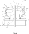
FIG. 4 is a sectional view of a header assembly having a MCRD in an insulator cavity of a ceramic helix mount. -
FIG. 5 is a perspective view of a header assembly having controlled therapeutic agent release. -
FIG. 6 is a sectional view of a header assembly having a MCRD within an electrode helix. -
FIG. 7 is a flowchart of a method of manufacturing a leadless biostimulator. - The present disclosure relates to a leadless biostimulator, e.g., a leadless cardiac pacemaker, having a header assembly that includes a monolithic controlled release device (MCRD) to elute therapeutic agent around an electrode. The leadless biostimulator may be used to pace cardiac tissue, e.g., in the ventricles or the atria of a heart. The leadless biostimulator may be used in other applications, however, such as deep brain stimulation. Thus, reference to the leadless biostimulator as being a cardiac pacemaker is not limiting.
- The use of relative terms throughout the description may denote a relative position or direction. For example, "distal" may indicate a first direction along a longitudinal axis of a leadless biostimulator. Similarly, "proximal" may indicate a second direction opposite to the first direction. Such terms are provided to establish relative frames of reference, however, and are not intended to limit the use or orientation of a leadless biostimulator to a specific configuration described in the various examples below.
- In an aspect, a leadless biostimulator includes a header assembly having an electrode extending longitudinally through an insulator cavity of an insulator. A MCRD containing a therapeutic agent can be located within the insulator cavity. For example, the MCRD can be retained within the insulator cavity by a distal tip of the electrode or via a press fit between the MCRD and an electrode helix of the electrode. The retained MCRD can therefore elute the therapeutic agent into the insulator cavity toward a target tissue when the leadless biostimulator is implanted in blood. For example, the therapeutic agent can elute through a space between the insulator and the electrode, and around the electrode through a channel of a helix mount to a surrounding environment. The channel of the helix mount can have sufficient cross-sectional area, e.g., an annular cross-sectional area, to permit blood and therapeutic agent to be exchanged between the MCRD and the surrounding environment. Accordingly, the header assembly described below can provide controlled therapeutic agent release.
- In an aspect, the electrode of the header assembly includes an electrode pin to carry pacing pulses distally toward the target tissue. Furthermore, the electrode can have a distal tip that includes a small distal surface area that can securely engage the target tissue. For example, the distal tip can be a cap mounted on a distal end of the electrode pin, or an electrode helix that can be screwed into the target tissue. The electrode can therefore provide consistent and stable surface area contact between the electrode and the target tissue. Accordingly, the header assembly described below can provide controlled impedance and pacing.
- Referring to
FIG. 1 , a perspective view of a leadless biostimulator. Abiostimulator 100 can be a leadless biostimulator, e.g., a leadless cardiac pacemaker used to deliver pacing impulses to the atria or ventricles of a heart. Thebiostimulator 100 can include ahousing 102 having electrodes. For example, thebiostimulator 100 includes each of adistal electrode 104 and aproximal electrode 106 disposed on or integrated into thehousing 102. Thedistal electrode 104 and theproximal electrode 106 can be used to sense and pace the heart. Theelectrodes housing 102 or connected to thehousing 102, e.g., at a distance of less than several centimeters from the housing. - In an example, the
housing 102 contains an energy source (not shown) to provide power to thepacing electrodes distal electrode 104, and an anode, e.g., theproximal electrode 106, of the device. The energy source can be, for example, a battery, such as a lithium carbon monofluoride (CFx) cell, or a hybrid battery, such as a combined CFx and silver vanadium oxide (SVO/CFx) mixed-chemistry cell. Similarly, the energy source can be an ultracapacitor. In one implementation, the energy source can be an energy harvesting device, such as a piezoelectric device that converts mechanical strain into electrical current or voltage. The energy source can also be an ultrasound transmitter that uses ultrasound technology to transfer energy from an ultrasound subcutaneous pulse generator to a receiver-electrode implanted on an endocardial wall. - The
housing 102 can have alongitudinal axis 108, which may be an axis of symmetry along which several other biostimulator components are disposed. For example, aheader assembly 110 can be mounted on a distal end of thehousing 102 along thelongitudinal axis 108. Theheader assembly 110 can include an electrical feedthrough assembly, incorporating aflange 112, ahelix mount 114, and ahelical fixation element 116 mounted on thehelix mount 114. The assembled components of theheader assembly 110, which are described further below, can provide a distal region of thebiostimulator 100 that attaches to the target tissue, e.g., via engagement of thefixation element 116 with the target tissue. The distal region can deliver a pacing impulse to the target tissue, e.g., via thedistal electrode 104 that is held against the target tissue, when theleadless biostimulator 100 is implanted in a surroundingenvironment 117, e.g., blood within an atrium or ventricle. - The
housing 102 can have an electronics compartment 118 (shown by hidden lines). More particularly, theelectronics compartment 118 can be a cavity laterally surrounded by a housing wall, e.g., a cylindrical wall, extending around thelongitudinal axis 108. The housing wall can include a conductive, biocompatible, inert, and anodically safe material such as titanium, 316L stainless steel, or other similar materials, to laterally enclose theelectronics compartment 118. More particularly, theelectronics compartment 118 can be enclosed between the energy source of the biostimulator 100 (that is within a proximal portion of the housing 102) and the header assembly 110 (that is at the distal portion of the biostimulator 100). The energy source container can proximally enclose theelectronics compartment 118 and theheader assembly 110 can distally enclose theelectronics compartment 118. Theheader assembly 110, the housing wall, and the energy source container can surround a volume of theelectronics compartment 118. - In one implementation, the
electronics compartment 118 contains an electronics assembly 120 (shown by hidden lines). Theelectronics assembly 120 can be mounted in theelectronics compartment 118. For example, theelectronics assembly 120 can include, without limitation, a flexible circuit or a printed circuit board having electrical connectors that connect to electrical pins of theheader assembly 110 and the energy source. As described below, theheader assembly 110 can include an electrode that connects to an electrical connector (e.g., a socket connector) of theelectronics assembly 120 within theelectronics compartment 118 to transmit pacing and sensing signals to and from the target tissue. Theelectronics assembly 120 has one or more electronic components mounted on a substrate. For example, theelectronics assembly 120 can include one or more processors, capacitors, etc., interconnected by electrical traces, vias, or other electrical connectors. The electronics components can be configured to perform sensing and pacing of the target tissue. - The biostimulator components, e.g., the energy source container, the
electronics compartment 118 containing theelectronics assembly 120, and theheader assembly 110, can be arranged on thelongitudinal axis 108. Accordingly, each component can extend along thelongitudinal axis 108 and have a respective axial location relative to another component along thelongitudinal axis 108. For example, the energy source container can be offset from theelectronics compartment 118 in aproximal direction 122 and theheader assembly 110 can be offset from theelectronics compartment 118 in adistal direction 124. - Referring to
FIG. 2 , a perspective view of a header assembly having controlled therapeutic agent release is shown. Theheader assembly 110 can perform several functions. First, theheader assembly 110 provides for fixation of theleadless biostimulator 100 to the target tissue via thehelical fixation element 116 mounted on thehelix mount 114. The fixation element can be screwed into the target tissue to retain theleadless biostimulator 100 with thedistal electrode 104 in contact with the target tissue. Second, theheader assembly 110 provides the electrical feedthrough from theelectronics compartment 118 to the surroundingenvironment 117 to allow for sensing and pacing of the target tissue. More particularly, the electrical feedthrough assembly of theheader assembly 110 can transmit electrical pulses through thedistal electrode 104 to the target tissue. Third, theheader assembly 110 contains a therapeutic agent between thehelix mount 114 and theflange 112 that can elute outward to the target tissue when theleadless biostimulator 100 is implanted in the surroundingenvironment 117. More particularly, fluid, e.g., blood, from the surroundingenvironment 117 can flow inward through agap 202 between thedistal electrode 104 and thehelix mount 114 to a space contained axially between thehelix mount 114 and theflange 112, and agent-laden fluid can then flow outward through thegap 202 toward the target tissue. - Referring to
FIG. 3 , a sectional view of a header assembly having a monolithic controlled release device (MCRD) between an insulator and electrode is shown. In certain implementations, each of the components of theheader assembly 110 may be symmetrically formed about thelongitudinal axis 108. For example, the cross-sectional area of theflange 112 illustrated inFIG. 3 can be swept about thelongitudinal axis 108 such that the outer surface has a profile as shown inFIG. 2 . In other implementations, the profiles of the components of theheader assembly 110 may be non-cylindrical. For example, a cross-section of theflange 112 taken about a transverse plane extending orthogonal to thelongitudinal axis 108 may reveal an outer surface of theflange 112 that is square, pentagonal, elliptical, etc., or any other suitable shape. Accordingly, the particular shapes illustrated in the figures are provided by way of example only and not necessarily by way of limitation. - The
flange 112 can be mounted on the housing 102 (FIG. 1 ). For example, aproximal flange end 302, e.g., a lip, may be mounted on a distal end of the housing wall that surrounds theelectronics compartment 118. Theflange 112 can be connected to thehousing 102 by a hermetic seal, e.g., a weld or any other similar hermetically sealed connection. For example, the hermetic weld can be formed circumferentially around a seam between theproximal flange end 302 and the distal end of the housing wall. - In an example, the
flange 112 includes ashoulder 304. Theflange 112 can have a flange wall extending distally from theproximal flange end 302 to theshoulder 304. Theshoulder 304 can be a transition region between the flange wall that extends substantially longitudinally, from theproximal flange end 302, to the flange wall that extends substantially transversely. In an example, theshoulder 304 has a distal shoulder surface that extends substantially transversely, and thus, the distal shoulder surface can extend transverse to thelongitudinal axis 108. Accordingly, the distal shoulder surface can face thedistal direction 124. The distal shoulder surface extends radially inward toward aflange connector 306. Theflange connector 306 can extend distally from the distal shoulder surface, and may receive thehelix mount 114. For example, theflange connector 306 can have an external thread that couples to an internal thread of thehelix mount 114. - The
flange 112 includes aflange channel 308 extending along thelongitudinal axis 108 from theproximal flange end 302 to a distal flange end. More particularly, theflange channel 308 can be a through-hole extending entirely through theflange 112 in the longitudinal direction. Theshoulder 304 of theflange 112 can extend around and circumferentially surround a proximal region of theflange channel 308. Similarly, theflange connector 306 can extend around and circumferentially surround a distal region of theflange channel 308. Accordingly, theshoulder 304 and theflange connector 306 can define theflange channel 308. The proximal region of theflange channel 308 can define a distal region of theelectronics compartment 118 that contains theelectronics assembly 120 when theflange 112 is mounted on thehousing 102. - The
header assembly 110 includes an insulator 310 in theflange channel 308. In an example, the insulator 310 includes an insulator wall 312 extending around an insulator cavity 314. The insulator wall 312 can extend longitudinally from a proximal end of the insulator 310 to a distal end of the insulator 310. For example, the insulator wall 312 can be a cylindrical, annular wall having an outer insulator surface facing radially outward, and aninner insulator surface 316 facing radially inward and partially defining the insulator cavity 314. The insulator 310 can also include aninsulator base 318 extending laterally at a location between the distal end and the proximal end of the insulator 310. Theinsulator base 318 can be a transverse wall extending across the interior of the insulator 310, orthogonal to thelongitudinal axis 108. Theinsulator base 318 can have an upper wall surface facing distally and partially defining the insulator cavity 314 of the insulator 310. Accordingly, the insulator 310 can be mounted within theflange channel 308 to insulate the insulator cavity 314 from themetallic flange connector 306, and to provide a receptacle for a therapeutic agent, as described below. - In an example, the
header assembly 110 includes theelectrode 104 mounted within the insulator 310 and theflange 112. More particularly, theelectrode 104 extends longitudinally through the insulator cavity 314 along thelongitudinal axis 108. Theelectrode 104 can include several components. For example, theelectrode 104 can include anelectrode pin 320 extending along thelongitudinal axis 108 from theelectronics compartment 118 through the insulator cavity 314 to adistal end 322. Thedistal end 322 may be located distal to the distal end of the insulator 310. In an example, theelectrode 104 includes anelectrode tip 324 at thedistal end 322. Theelectrode tip 324 can be a cap that is mounted on, and bonded to, thedistal end 322. For example, theelectrode tip 324 can include an electrode cap having a counterbore or a through-hole to receive, and be welded to, the distal, tissue-facing end of theelectrode pin 320. Alternatively, theelectrode tip 324 can be a portion of the electrode that is formed to have a different dimension than theelectrode pin 320. For example, theelectrode tip 324 can having an outer dimensions that is greater than an outer dimension of theelectrode pin 320. Theelectrode tip 324 may therefore have a proximal surface that faces the insulator cavity 314 to restrict the elution of therapeutic agent distally from the insulator cavity 314. - The
electrode tip 324 can act as the active, tissue-touching electrode to sense and deliver electrical impulses to the target tissue. In an example, a distal surface area of theelectrode tip 324 is sized to provide predetermined impedance parameters. Theelectrode 104, e.g., the pin and the cap, can be formed from platinum iridium or another biocompatible conductor. Based on the electrical properties of the electrode material, the distal surface area can be sized to provide a predetermined impedance at the contact area between the target tissue and the electrode. Generally, the smaller the distal surface area, the larger the impedance. Given that theelectrode tip 324 can be formed to be quite small, and because the tip will reliably engage the target tissue over the surface area, the impedance of the electrode can be controllable and suitably high for reliable pacing. It will be appreciated that the electrical feedthrough assembly can be a filtered or unfiltered assembly, as is known in the art. More particularly, the electrical feedthrough assembly can incorporate an integral EMI filter capacitor in electrical communication with the electrode 104 (filtered feedthrough assembly) or not (unfiltered feedthrough assembly). - In an example, the
flange 112, the insulator 310, and theelectrode 104 are joined. For example, a joint 326 can be formed between theflange 112, the insulator 310, and theelectrode 104 to fasten the components together and to provide a hermetic seal between the flange channel region proximal to the insulator 310 (e.g., the electronic compartment) and the flange channel region distal to the insulator 310. In an example, the joint 326 is a brazed joint, e.g., a gold brazed joint, which radially surrounds a portion of the components to fill gaps between the components and form the hermetic joint. Theelectrode 104 can pass through the joint 326, and through a hole in theinsulator base 318, to transfer electrical signals between the target tissue and the internal circuitry of theleadless biostimulator 100. - In an example, the
header assembly 110 includes aMCRD 330. TheMCRD 330 can be an agent-containing filler that is located in the insulator cavity 314. For example, theMCRD 330 can include a therapeutic agent loaded into a matrix or solid composition. In at least one implementation, the therapeutic agent can include a corticosteroid, such as dexamethasone sodium phosphate, dexamethasone acetate, etc. When the therapeutic agent is consistently released into the target tissue at a controlled dose, the agent can reduce inflammation associated with the device implantation. - The
MCRD 330 can be placed or located in the insulator cavity 314 radially inward from the insulator wall 312 and distal to theinsulator base 318. Elution of the therapeutic agent from theMCRD 330 can be controlled by a geometry of theMCRD 330, as well as by the ingress and egress of fluid, e.g., blood, from the surroundingenvironment 117 into the insulator cavity 314. Accordingly, theheader assembly 110 can be configured to allow for fluid transport between theMCRD 330 and the surroundingenvironment 117 through the insulator cavity 314. A specified dose of the therapeutic agent may therefore flow, or weep, from theMCRD 330 through the insulator cavity 314 and thehelix mount 114 to the target tissue at an implantation site of thebiostimulator 100 within a patient. - In an example, the
MCRD 330 is in fluid communication with a space 332 between the insulator 310 and theelectrode 104 to elute the therapeutic agent into the space 332 when theleadless biostimulator 100 is implanted in blood. The space 332 can be between theinner insulator surface 316 and anouter electrode surface 317 of theelectrode 104. More particularly, the space 332 can be defined radially between theinner insulator surface 316 and theouter electrode surface 317. Furthermore, the space 332 can be defined longitudinally between theinsulator base 318 and a distal end of the insulator 310. Accordingly, the space 332 is an annular region of the insulator cavity 314 defined between theelectrode 104 and the insulator 310. - In an example, the
MCRD 330 can be received within the space 332. For example, theMCRD 330 can have an annular body 334 that is located between theelectrode 104 and the insulator 310 within the insulator cavity 314, and thus, may be positioned within the space 332. The annular body 334 can include an outer surface and an inner surface that are generally cylindrical and extend between proximal anddistal ends 322 of theMCRD 330. The inner surface of theMCRD 330 can define acentral lumen 336 that extends longitudinally through theMCRD 330. In an example, thecentral lumen 336 receives theelectrode 104. For example, theelectrode pin 320 can extend longitudinally through thecentral lumen 336 to thedistal end 322 that is distal to the distal end of theMCRD 330. Therapeutic agent eluted from theMCRD 330 is therefore initially in the space 332 between theelectrode pin 320 and the inner surface of the insulator 310. The therapeutic agent, after elution, can be carried outward by blood transfer to the surroundingenvironment 117. - The
header assembly 110 can include thehelix mount 114. Thehelix mount 114 may be formed from an insulating material, such as a ceramic material (e.g., alumina, ruby, glass, or another ceramic insulating material) and/or a non-ceramic material (e.g., polyetheretherketone (PEEK)). Thehelix mount 114 can be mounted on theflange 112. For example, thehelix mount 114 can have an inner surface that is threaded to engage external threads of theflange connector 306. Thehelix mount 114 may also include an external threaded feature. More particularly, thehelix mount 114 can include amount flange 340, which may be a helical ledge extending around an outer surface of thehelix mount 114. Themount flange 340 can receive thehelical fixation element 116. More particularly, thehelical fixation element 116 can be mounted on thehelix mount 114 by screwing the fixation element onto the helical ledge until a distal tip of the fixation element is properly located for tissue engagement. - In an example, the
helix mount 114 includes ahelix mount channel 342 through which therapeutic agent can be eluted when theleadless biostimulator 100 is implanted in blood. Thehelix mount channel 342 can be a hole extending through a distal wall of thehelix mount 114. The hole can be centrally located, e.g., along thelongitudinal axis 108, such that thehelix mount channel 342 is concentric with theelectrode pin 320 and/or theelectrode tip 324. Furthermore, thehelix mount channel 342 can have a hole dimension that is larger than theelectrode pin 320 and theelectrode tip 324 such that theannular gap 202 is formed between thehelix mount 114 and theelectrode 104. More particularly, theannular gap 202 can be a gap formed around theelectrode 104 and extending from the insulator cavity 314 to the surroundingenvironment 117 to provide an elution path for the therapeutic agent to be transferred through. Accordingly, when theleadless biostimulator 100 is implanted, blood can enter the insulator cavity 314 through theannular gap 202 to dissolve the therapeutic agent and transfer the drug-laden agent through the space 332 and thehelix mount channel 342 to the surroundingenvironment 117. Advantageously, theannular gap 202 may be less likely to clog than a single small hole, and thus, may promote consistent and continuous elution of the therapeutic agent into the target tissue. - The
flange 112 may be a portion of theproximal electrode 106, and thus, the electrical feedthrough assembly of theheader assembly 110 may also include theproximal electrode 106. In such case, the electrodes (theelectrode tip 324 and the flange 112) may be in close proximity, separated by an electrode gap extending radially between theflange connector 306 and theelectrode 104. If blood were allowed to fill the electrode gap between theflange 112 and theelectrode 104, theelectrodes biostimulator 100 to prevent blood from filling the electrode gap and/or to block an electrical path between theflange 112 and theelectrode 104. In an example, the barrier includes agasket 350. Thegasket 350 can be an annular seal that is pressed between a distal end of theflange connector 306 and the insulator 310, and a proximal inner surface of thehelix mount 114. Thegasket 350 bridges the gap between theinsulative helix mount 114 and insulator 310, and thus, blood that enters the insulator cavity 314 to facilitate therapeutic agent release does not contact theflange 112. - In an example, the
MCRD 330 is retained in part by theelectrode 104. For example, theelectrode tip 324 can have an outer dimension that is greater than a dimension of theMCRD 330central lumen 336. Accordingly, theMCRD 330 may be restrained from sliding off of theelectrode 104 into the surroundingenvironment 117. Furthermore, an inner dimension of thehelix mount channel 342 may be less than a dimension of thecentral lumen 336 of theMCRD 330. Accordingly, theMCRD 330 may be restrained from sliding out of the insulator cavity 314 by thehelix mount 114. - Instead of or in addition to the retention features described above, the
MCRD 330 may be partly retained via a press fit against one or more of the insulator 310 or theelectrode 104. More particularly, the outer surface of theMCRD 330 may press against theinner insulator surface 316 of the insulator 310 and/or the inner surface of theMCRD 330 may press against theouter electrode surface 317. Accordingly, friction caused by a press fit between theMCRD 330 and one or more of the insulator 310 or theelectrode 104 can retain theMCRD 330 within the insulator cavity 314. In an example, at least one of the side surfaces of theMCRD 330 has a clearance with an opposing surface of the insulator 310 or theelectrode 104. For example, when theMCRD 330 is press fit against the insulator 310, theMCRD 330 may have a clearance fit with the electrode 104 (FIG. 3 ). The clearance can maximize the MCRD surface area exposed to blood after implantation to promote elution of the therapeutic agent into the space 332. - Optionally, the
MCRD 330 can include a time-release coating. The time-release coating may be applied, e.g., by spray or dip coating, to an exterior surface of theMCRD 330. The time release coating can be an absorbable coating, such as a hydrophilic coating, that absorbs within minutes to an hour of being in contact with blood. Accordingly, the exterior surface can contact blood when thebiostimulator 100 is implanted, and the release of therapeutic agent can be delayed while the coating dissolves. After the coating dissolves, the therapeutic agent can elute from theMCRD 330 and follow an elution path through the space 332 and thehelix mount channel 342 toward the surroundingenvironment 117. - Referring to
FIG. 4 , a sectional view of a header assembly having a MCRD in an insulator cavity of a ceramic helix mount is shown. Theheader assembly 110 can include ahelix mount 114 that combines features of the insulator 310 and thehelix mount 114 described above with respect toFIG. 3 . More particularly, the insulator 310 and thehelix mount 114 are monolithically formed from ceramic. The fully-ceramic helix mount 114 can connect to theflange 112 via a threaded or threadless connector that attaches theflange connector 306 to thehelix mount 114. For example, thehelix mount 114 can be screwed onto theflange connector 306 to secure theflange 112 to thehelix mount 114. Similarly, the fixation element can be screwed onto themount flange 340. - In an example, the
helix mount 114 can have a hole extending from a proximal end of thehelix mount 114 to a distal end of thehelix mount 114. Theelectrode 104 can be inserted into the hole, and secured by the joint 326, as described above. More particularly, the joint 326 can be a brazed joint securing and sealing theelectrode 104 to thehelix mount 114. Accordingly, theheader assembly 110 can include theflange 112, the helix mount 114 (which incorporates the insulator 310), and theelectrode 104 securely fastened to each other and hermetically sealed to prevent ingress of blood from the surroundingenvironment 117 into theelectronics compartment 118. - The insulator cavity 314 can be formed directly into the
helix mount 114. More particularly, a counterbore can be formed in a distal end of the fully-ceramic helix mount 114 such that the counterbore includes theinner insulator surface 316. When theelectrode 104 is secured relative to thehelix mount 114, theinner insulator surface 316 faces theouter electrode surface 317, providing the space 332 between the insulator 310 and theelectrode 104. TheMCRD 330 can be loaded into the space 332, and thus, can elute therapeutic agent into the space 332 when thebiostimulator 100 is implanted in blood. - The
electrode 104 may include a through-post configuration. The through-post configuration includes anelectrode tip 324 having a through-hole to receive theelectrode pin 320. More particularly, when theelectrode pin 320 is inserted into the through-hole of theelectrode tip 324, thedistal end 322 of theelectrode pin 320 can be exposed to the surroundingenvironment 117. - In an example, the
electrode pin 320 includes astop 402 to provide a positional reference to theelectrode tip 324. Thestop 402 can include a protuberance or a ledge extending radially from the longitudinal pin of theelectrode 104. An outer dimension of thestop 402 may be greater than an inner dimension of the electrode tip through-hole, and thus, when theelectrode tip 324 is inserted over thedistal end 322 of theelectrode pin 320, theelectrode tip 324 can rest on thestop 402. Theelectrode tip 324 may then be welded or otherwise attached to theelectrode pin 320 to form theelectrode 104. - As described above, the
MCRD 330 can be located within the insulator cavity 314 between theelectrode 104 and the insulator 310. For example, an inner dimension of theMCRD 330 extending around thecentral lumen 336 may be less than an outer dimension of theelectrode tip 324. Thus, theelectrode tip 324 can retain theMCRD 330 within the space 332 of the insulator cavity 314. Also as described above, theMCRD 330 can elute therapeutic agent through the space 332 and through theannular gap 202 to the surroundingenvironment 117 when thebiostimulator 100 is implanted in blood. - Combining the insulator 310 and the
helix mount 114 in a fully-ceramic helix mount 114, as described above, can reduce an overall height of theheader assembly 110. As illustrated, with the fullyceramic helix mount 114, the height of theflange connector 306 and the height of thehelix mount 114 can be reduced, which shortens theheader assembly 110. Advantageously, by shortening theheader assembly 110, the device length may instead be devoted to extending a length of the energy source. Accordingly, an energy capacity and operational longevity can be extended as compared tobiostimulators 100 havingnon-integrated helix mount 114 and insulator 310 components. - Referring to
FIG. 5 , a perspective view of a header assembly having controlled therapeutic agent release is shown. Theheader assembly 110 can include a fully-ceramic helix mount 114, as described above. In an example, theelectrode 104 of theheader assembly 110 includes anelectrode helix 502. Theelectrode helix 502 can provide a distal portion of theelectrode 104. More particularly, theelectrode helix 502 can be a portion of theelectrode 104 that engages tissue during implantation. For example, theelectrode helix 502 can be coaxial with thehelical fixation element 116 and, during implantation, both thehelical fixation element 116 and theelectrode helix 502 can be screwed into the target tissue. - An
electrode helix 502, like theelectrode tip 324 described above, can provide controlled impedance for reliable pacing. In the case of theelectrode helix 502, theelectrode 104 can be securely and predictably engaged with the target tissue by virtue of the electrode anchoring within the tissue. The anchored electrode can provide consistent tissue contact from case to case, and may therefore provide for more predictable impedance between the electrode and the tissue. Accordingly, the helical electrode can provide more consistent impedance and pacing. - Referring to
FIG. 6 , a sectional view of a header assembly having a MCRD within an electrode helix is shown. Several features of the embodiment shown inFIG. 6 are similar to those described above with respect toFIGS. 3 and4 , and thus, are not described again in the interest of brevity. - The
electrode pin 320 can extend longitudinally through the insulator cavity 314. In an example, theelectrode helix 502 is mounted on theelectrode pin 320. For example, theelectrode helix 502 can be slipped over and mounted on thedistal end 322 of theelectrode pin 320. Theelectrode pin 320 may include thestop 402, and thus, theelectrode helix 502 can rest on thestop 402. Theelectrode helix 502 may therefore be welded to theelectrode pin 320 in a consistent manner. More particularly, thestop 402 can provide a positional reference to ensure that theelectrode helix 502 is properly located relative to the fixation element. Theelectrode pin 320 and theelectrode helix 502 may therefore be joined to form theelectrode 104 that carries electrical signals between theelectronics compartment 118 and the target tissue that theelectrode helix 502 is screwed into. - In an example, the
MCRD 330 has a cylindrical shape. More particularly, theMCRD 330 can be a cylindrical plug, having no central channel, and may be inserted into the inner lumen of theelectrode helix 502. Alternatively, theMCRD 330 can have the annular or ring-shaped structure described above, and may be loaded into theelectrode helix 502. The plug can be press fit within theelectrode helix 502. Accordingly, the press fit between theelectrode helix 502 and theMCRD 330 can retain the MCRD and prevent dislodgement of the MCRD from the insulator cavity 314. - It will be appreciated that, although the
MCRD 330 is radially inward from the electrode helix 502 (rather than being radially outward from theelectrode pin 320 as shown inFIGS. 3-4 ), theMCRD 330 can still elute therapeutic agent along an elution path that passes through the space 332 between the insulator 310 and theelectrode 104. More particularly, when blood enters the insulator cavity 314, the therapeutic agent can be dissolved and flow radially outward from the inner lumen of the helix through the helical turns into the space 332 between theouter electrode surface 317 of the helical turns and theinner insulator surface 316 of thehelix mount 114. From the space 332, the therapeutic agent can travel distally outward from the insulator cavity 314 into the surroundingenvironment 117 through theannular gap 202. Advantageously, elution through the space 332 can allow for the therapeutic agent to be released controllably through theannular gap 202 that is larger and less likely to be clogged than a single hole in an electrode cup, for example. - Referring to
FIG. 7 , a flowchart of a method of manufacturing a leadless biostimulator is shown. As a preliminary operation, the insulator 310 can be loaded into theflange channel 308 such that the insulator cavity 314 and theflange channel 308 are concentric. The insulator 310 may have a thin, metallic coating deposited on its outer surface to allow for a brazing process to be performed on it, as described below. Theelectrode 104 can be loaded into the concentrically arrangedflange channel 308 and insulator cavity 314. More particularly, theelectrode pin 320 can be inserted into the hole in theinsulator base 318 such that theelectrode 104 extends longitudinally through the insulator cavity 314. Theelectrode pin 320 can be cut to a length (before or after loading the electrode into the assembly) such that theelectrode pin 320 extends to a predetermined length distal to and proximal to theinsulator base 318. The distal portion of theelectrode pin 320 can have a length to align thedistal end 322 of the pin with thehelix mount channel 342. The proximal region of theelectrode pin 320 can have a length to extend to a proximal end of the pin that will engage theelectronics assembly 120 in theelectronics compartment 318. - At
operation 702, theflange 112, the insulator 310, and theelectrode 104 are joined together. The concentrically arranged components can be secured by the joint 326. In an example, gold is flowed into the junctions between the components in a brazing process. The molten gold can be cooled to braze the components together to provide a hermetic seal through which theelectrode 104 can pass electrical signals. - At
operation 704, theMCRD 330 is mounted within the insulator cavity 314. In an example, theMCRD 330 can be loaded over theelectrode 104, e.g., by inserting theelectrode pin 320 through the central channel of theannular MCRD 330. Alternatively, theMCRD 330 can be loaded into theelectrode 104, e.g., by sliding theMCRD 330 into an interior lumen of theelectrode helix 502. - After loading the
MCRD 330 into the insulator cavity 314, theMCRD 330 can be retained to a degree. For example, theMCRD 330 can form a press fit to one or more of the insulator wall 312, theelectrode pin 320, or theelectrode helix 502, depending upon the header assembly configuration being manufactured. Atoperation 706, theMCRD 330 may be further retained. More particularly, theelectrode tip 324 or theelectrode helix 502 can be mounted on thedistal end 322 of theelectrode pin 320 to retain theMCRD 330 within the insulator cavity 314. In the case of theelectrode tip 324, theelectrode 104 can include a cap that has a larger outer dimension than thecentral lumen 336 of theMCRD 330, and thus, the cap can resist distal movement of theMCRD 330 from theelectrode pin 320. In the case of theelectrode helix 502, theMCRD 330 can be press fit within the interior of the helix. Theelectrode helix 502 can be connected, e.g., welded, to adistal end 322 of theelectrode pin 320, and thus, theelectrode helix 502 can resist distal movement of theMCRD 330 relative to theelectrode pin 320. In either case, the electrode features can both retain theMCRD 330 within the insulator cavity 314 and provide electrical conduction of pacing signals to the target tissue. - The operations of the method may be performed in an alternative order. For example, for the header assembly configuration shown in
FIG. 6 , the operation of mounting (and optionally welding) theelectrode helix 502 on theelectrode pin 320 atoperation 706 may precede the operation of loading theMCRD 330 into the electrode helix 502 (and the insulator cavity 314) atoperation 704. Accordingly, it will be appreciated that the operations may be reordered, omitted, or modified as needed to manufacture the header assembly configurations described above. - At
operation 708, thehelix mount 114 is mounted on theflange 112. Thehelix mount 114 can be fastened to theflange connector 306, e.g., by engaging mating threads of the components. Alternatively, other fasteners can secure thehelix mount 114 to theflange 112. When thehelix mount 114 is attached to theflange 112, thehelix mount channel 342 can be positioned to receive theelectrode 104, e.g., theelectrode tip 324, such that thegap 202 provides an elution pathway between the insulator cavity 314 within theheader assembly 110 and the surroundingenvironment 117. Thegap 202 can be sized to achieve good fluid exchange between the interior and the exterior of theheader assembly 110. - At
operation 710, thehelical fixation element 116 is mounted on thehelix mount 114. Thehelical fixation element 116 can be screwed onto themount flange 340. Optionally, the fixation element can be adhered to themount flange 340 by a thermal or adhesive weld. Accordingly, the fixation element can be secured to thehelix mount 114 to retain theheader assembly 110 against the target tissue when the fixation element is screwed into the target tissue during device implantation. - In the foregoing specification, the invention has been described and will be evident that various modifications may be made thereto without departing from the scope of the invention as set forth in the following claims. The specification and drawings are, accordingly, to be regarded in an illustrative sense rather than a restrictive sense.
Claims (15)
- A header assembly (110) for a leadless biostimulator (100), comprising:a flange (112) including a flange channel (308) extending along a longitudinal axis (108);an insulator (310) in the flange channel (308) and including an insulator cavity (314);an electrode (104) extending longitudinally through the insulator cavity (314); anda monolithic controlled release device (MCRD) (330) in the insulator cavity (314), characterized in that the MCRD (330) is within a space (332) radially between the insulator (310) in the flange channel (308) and the electrode (104) to elute therapeutic agent into the space (332) when the leadless biostimulator (100) is implanted.
- The header assembly of claim 1, wherein the space (332) is between an inner insulator surface (316) of the insulator (310) and an outer electrode surface (317) of the electrode (104) within the insulator cavity (314).
- The header assembly of claim 1 or 2, wherein the MCRD (330) has an annular body including a central lumen (336), and wherein the electrode (104) extends longitudinally through the central lumen (336).
- The header assembly of any one of claims 1 to 3, wherein the electrode (104) includes an electrode pin (320) extending longitudinally through the insulator cavity (314), and an electrode tip (324) mounted on a distal end of the electrode pin (320).
- The header assembly of any one of claims 1 to 3, wherein the electrode (104) includes an electrode pin (320) extending longitudinally through the insulator cavity (314), and an electrode helix (502) mounted on a distal end of the electrode pin (302).
- The header assembly of any one of claims 1 to 5, further comprising:a helix mount (114) mounted on the flange (112), wherein the helix mount (114) includes a helix mount channel (342) in fluid communication with the space (332) such that the therapeutic agent elutes through the space (332) and the helix mount channel (342) to a surrounding environment (117) when the leadless biostimulator (100) is implanted; anda helical fixation element (116) mounted on the helix mount (114).
- The header assembly of claim 6, wherein the helix mount channel (342) includes an annular gap (202) between the helix mount (114) and the electrode (104).
- The header assembly of claim 6 or 7, wherein the insulator (310) and the helix mount (114) are monolithically formed from ceramic.
- The header assembly of any one of claims 1 to 8, wherein the MCRD (330) is press fit against one or more of the insulator (310) or the electrode (104).
- A leadless biostimulator (100), comprising:a housing (102) having an electronics compartment (118) containing an electronics assembly (120); andthe header assembly (110) of any one of claims 1 to 9 mounted on the housing (102).
- A method of manufacturing a leadless biostimulator (100), comprising:joining a flange (112), an insulator (310), and an electrode (104) such that the insulator (310) is in a flange channel (308) of the flange (112) and the electrode (104) extends along a longitudinal axis (108) through the flange channel (308) of the flange (112) and an insulator cavity (314) of the insulator (310); andmounting a monolithic controlled release device (MCRD) (330) within the insulator cavity (314), characterized in that the MCRD (330) is within a space (332) radially between the insulator (310) in the flange channel (308) and the electrode (104) to elute therapeutic agent into the space (332) when the leadless biostimulator (100) is implanted.
- The method of claim 11, wherein the MCRD (330) has an annular body including a central lumen (336), and wherein the electrode (104) extends longitudinally through the central lumen (336).
- The method of claim 11 or 12 further comprising mounting an electrode tip (324) or an electrode helix (502) on a distal end of an electrode pin (320) of the electrode (104).
- The method of any one of claims 11 to 13, further comprising:mounting a helix mount (114) on the flange (112), wherein the helix mount (114) includes a helix mount channel (342) in fluid communication with the space (332) such that the therapeutic agent elutes through the space (332) and the helix mount channel (342) to a surrounding environment (117) when the leadless biostimulator (110) is implanted; andmounting a helical fixation element (116) on the helix mount (114).
- The method of anyone of claims 11 to 14, further comprising press fitting the MCRD (330) against one or more of the insulator (310) and the electrode (104).
Applications Claiming Priority (2)
| Application Number | Priority Date | Filing Date | Title |
|---|---|---|---|
| US202163182687P | 2021-04-30 | 2021-04-30 | |
| US17/555,217 US12599764B2 (en) | 2021-04-30 | 2021-12-17 | Header assembly having controlled therapeutic agent release |
Publications (2)
| Publication Number | Publication Date |
|---|---|
| EP4082604A1 EP4082604A1 (en) | 2022-11-02 |
| EP4082604B1 true EP4082604B1 (en) | 2025-03-05 |
Family
ID=81392891
Family Applications (1)
| Application Number | Title | Priority Date | Filing Date |
|---|---|---|---|
| EP22170416.6A Active EP4082604B1 (en) | 2021-04-30 | 2022-04-28 | Header assembly having controlled therapeutic agent release |
Country Status (3)
| Country | Link |
|---|---|
| US (1) | US12599764B2 (en) |
| EP (1) | EP4082604B1 (en) |
| CN (1) | CN115253081A (en) |
Families Citing this family (1)
| Publication number | Priority date | Publication date | Assignee | Title |
|---|---|---|---|---|
| US20240316347A1 (en) * | 2023-03-21 | 2024-09-26 | Pacesetter, Inc. | Biostimulator having movable pacing element |
Family Cites Families (7)
| Publication number | Priority date | Publication date | Assignee | Title |
|---|---|---|---|---|
| WO2016130477A2 (en) | 2015-02-09 | 2016-08-18 | Cardiac Pacemakers, Inc. | Implantable medical device with radiopaque id tag |
| CN111601640B (en) * | 2017-11-06 | 2024-04-09 | 先导者股份有限公司 | Biostimulator with fixed elements |
| US10821282B2 (en) * | 2018-05-21 | 2020-11-03 | Pacesetter, Inc. | Shaped monolithic controlled release device for improved drug release in implantable medical leads and leadless pacemakers |
| EP3870267B1 (en) | 2018-10-25 | 2024-06-19 | Pacesetter, Inc. | Biostimulator feedthrough having integrated electrode cup |
| US11541243B2 (en) | 2019-03-15 | 2023-01-03 | Pacesetter, Inc. | Biostimulator having coaxial fixation elements |
| US11684789B2 (en) | 2020-01-27 | 2023-06-27 | Pacesetter, Inc. | Biostimulator header assembly having ceramic helix mount |
| US11992675B2 (en) * | 2020-02-04 | 2024-05-28 | Medtronic, Inc. | Implantable medical device including a tine housing |
-
2021
- 2021-12-17 US US17/555,217 patent/US12599764B2/en active Active
-
2022
- 2022-04-28 EP EP22170416.6A patent/EP4082604B1/en active Active
- 2022-04-29 CN CN202210473535.5A patent/CN115253081A/en active Pending
Also Published As
| Publication number | Publication date |
|---|---|
| CN115253081A (en) | 2022-11-01 |
| US12599764B2 (en) | 2026-04-14 |
| US20220347467A1 (en) | 2022-11-03 |
| EP4082604A1 (en) | 2022-11-02 |
Similar Documents
| Publication | Publication Date | Title |
|---|---|---|
| US12102830B2 (en) | Leadless biostimulator and electrical feedthrough assembly for leadless biostimulator | |
| US11559694B2 (en) | Methods of manufacturing a hermetic lead connector | |
| US12458806B2 (en) | Biostimulator header assembly having a helix mount including a mount boss | |
| US5851221A (en) | Attachment apparatus and method for an implantable medical device | |
| EP2773416B1 (en) | Leadless cardiac pacemaker with integral battery and redundant welds | |
| US12576278B2 (en) | Leadless biostimulator having overmolded header assembly | |
| US12364866B2 (en) | Biostimulator header assembly having integrated antenna | |
| US10734139B2 (en) | Ferrule having improved gold reservoir geometry for implantable medical device | |
| US9168376B2 (en) | Implantable device with opposing lead connectors | |
| US12599764B2 (en) | Header assembly having controlled therapeutic agent release | |
| EP3972688A1 (en) | Feedthrough assembly with feature for controlling component position | |
| US12285619B2 (en) | Header assembly having threadless interconnection | |
| US20230191139A1 (en) | Feedthrough insulator cap for medical device battery | |
| EP4647110A1 (en) | Biostimulator header assembly having integrated fixation element mount | |
| EP3573710B1 (en) | Medical device including feedthrough assembly | |
| US20260115485A1 (en) | Biostimulator having a radiopaque marker |
Legal Events
| Date | Code | Title | Description |
|---|---|---|---|
| PUAI | Public reference made under article 153(3) epc to a published international application that has entered the european phase |
Free format text: ORIGINAL CODE: 0009012 |
|
| STAA | Information on the status of an ep patent application or granted ep patent |
Free format text: STATUS: THE APPLICATION HAS BEEN PUBLISHED |
|
| AK | Designated contracting states |
Kind code of ref document: A1 Designated state(s): AL AT BE BG CH CY CZ DE DK EE ES FI FR GB GR HR HU IE IS IT LI LT LU LV MC MK MT NL NO PL PT RO RS SE SI SK SM TR |
|
| STAA | Information on the status of an ep patent application or granted ep patent |
Free format text: STATUS: REQUEST FOR EXAMINATION WAS MADE |
|
| 17P | Request for examination filed |
Effective date: 20230222 |
|
| RBV | Designated contracting states (corrected) |
Designated state(s): AL AT BE BG CH CY CZ DE DK EE ES FI FR GB GR HR HU IE IS IT LI LT LU LV MC MK MT NL NO PL PT RO RS SE SI SK SM TR |
|
| P01 | Opt-out of the competence of the unified patent court (upc) registered |
Effective date: 20230616 |
|
| GRAP | Despatch of communication of intention to grant a patent |
Free format text: ORIGINAL CODE: EPIDOSNIGR1 |
|
| STAA | Information on the status of an ep patent application or granted ep patent |
Free format text: STATUS: GRANT OF PATENT IS INTENDED |
|
| RIC1 | Information provided on ipc code assigned before grant |
Ipc: A61N 1/05 20060101ALN20241023BHEP Ipc: A61N 1/372 20060101ALN20241023BHEP Ipc: A61M 37/00 20060101ALI20241023BHEP Ipc: A61N 1/375 20060101AFI20241023BHEP |
|
| INTG | Intention to grant announced |
Effective date: 20241111 |
|
| GRAS | Grant fee paid |
Free format text: ORIGINAL CODE: EPIDOSNIGR3 |
|
| GRAA | (expected) grant |
Free format text: ORIGINAL CODE: 0009210 |
|
| STAA | Information on the status of an ep patent application or granted ep patent |
Free format text: STATUS: THE PATENT HAS BEEN GRANTED |
|
| AK | Designated contracting states |
Kind code of ref document: B1 Designated state(s): AL AT BE BG CH CY CZ DE DK EE ES FI FR GB GR HR HU IE IS IT LI LT LU LV MC MK MT NL NO PL PT RO RS SE SI SK SM TR |
|
| REG | Reference to a national code |
Ref country code: GB Ref legal event code: FG4D |
|
| REG | Reference to a national code |
Ref country code: CH Ref legal event code: EP |
|
| REG | Reference to a national code |
Ref country code: DE Ref legal event code: R096 Ref document number: 602022011310 Country of ref document: DE |
|
| REG | Reference to a national code |
Ref country code: IE Ref legal event code: FG4D |
|
| PG25 | Lapsed in a contracting state [announced via postgrant information from national office to epo] |
Ref country code: RS Free format text: LAPSE BECAUSE OF FAILURE TO SUBMIT A TRANSLATION OF THE DESCRIPTION OR TO PAY THE FEE WITHIN THE PRESCRIBED TIME-LIMIT Effective date: 20250605 |
|
| PG25 | Lapsed in a contracting state [announced via postgrant information from national office to epo] |
Ref country code: FI Free format text: LAPSE BECAUSE OF FAILURE TO SUBMIT A TRANSLATION OF THE DESCRIPTION OR TO PAY THE FEE WITHIN THE PRESCRIBED TIME-LIMIT Effective date: 20250305 |
|
| PGFP | Annual fee paid to national office [announced via postgrant information from national office to epo] |
Ref country code: DE Payment date: 20250409 Year of fee payment: 4 |
|
| REG | Reference to a national code |
Ref country code: NL Ref legal event code: MP Effective date: 20250305 |
|
| PG25 | Lapsed in a contracting state [announced via postgrant information from national office to epo] |
Ref country code: ES Free format text: LAPSE BECAUSE OF FAILURE TO SUBMIT A TRANSLATION OF THE DESCRIPTION OR TO PAY THE FEE WITHIN THE PRESCRIBED TIME-LIMIT Effective date: 20250305 |
|
| REG | Reference to a national code |
Ref country code: LT Ref legal event code: MG9D |
|
| PG25 | Lapsed in a contracting state [announced via postgrant information from national office to epo] |
Ref country code: NO Free format text: LAPSE BECAUSE OF FAILURE TO SUBMIT A TRANSLATION OF THE DESCRIPTION OR TO PAY THE FEE WITHIN THE PRESCRIBED TIME-LIMIT Effective date: 20250605 |
|
| PGFP | Annual fee paid to national office [announced via postgrant information from national office to epo] |
Ref country code: IT Payment date: 20250430 Year of fee payment: 4 |
|
| PG25 | Lapsed in a contracting state [announced via postgrant information from national office to epo] |
Ref country code: HR Free format text: LAPSE BECAUSE OF FAILURE TO SUBMIT A TRANSLATION OF THE DESCRIPTION OR TO PAY THE FEE WITHIN THE PRESCRIBED TIME-LIMIT Effective date: 20250305 |
|
| PG25 | Lapsed in a contracting state [announced via postgrant information from national office to epo] |
Ref country code: LV Free format text: LAPSE BECAUSE OF FAILURE TO SUBMIT A TRANSLATION OF THE DESCRIPTION OR TO PAY THE FEE WITHIN THE PRESCRIBED TIME-LIMIT Effective date: 20250305 |
|
| PG25 | Lapsed in a contracting state [announced via postgrant information from national office to epo] |
Ref country code: GR Free format text: LAPSE BECAUSE OF FAILURE TO SUBMIT A TRANSLATION OF THE DESCRIPTION OR TO PAY THE FEE WITHIN THE PRESCRIBED TIME-LIMIT Effective date: 20250606 Ref country code: BG Free format text: LAPSE BECAUSE OF FAILURE TO SUBMIT A TRANSLATION OF THE DESCRIPTION OR TO PAY THE FEE WITHIN THE PRESCRIBED TIME-LIMIT Effective date: 20250305 |
|
| PGFP | Annual fee paid to national office [announced via postgrant information from national office to epo] |
Ref country code: CH Payment date: 20250501 Year of fee payment: 4 |
|
| REG | Reference to a national code |
Ref country code: AT Ref legal event code: MK05 Ref document number: 1772381 Country of ref document: AT Kind code of ref document: T Effective date: 20250305 |
|
| PG25 | Lapsed in a contracting state [announced via postgrant information from national office to epo] |
Ref country code: NL Free format text: LAPSE BECAUSE OF FAILURE TO SUBMIT A TRANSLATION OF THE DESCRIPTION OR TO PAY THE FEE WITHIN THE PRESCRIBED TIME-LIMIT Effective date: 20250305 |
|
| PG25 | Lapsed in a contracting state [announced via postgrant information from national office to epo] |
Ref country code: SE Free format text: LAPSE BECAUSE OF FAILURE TO SUBMIT A TRANSLATION OF THE DESCRIPTION OR TO PAY THE FEE WITHIN THE PRESCRIBED TIME-LIMIT Effective date: 20250305 |
|
| PG25 | Lapsed in a contracting state [announced via postgrant information from national office to epo] |
Ref country code: SM Free format text: LAPSE BECAUSE OF FAILURE TO SUBMIT A TRANSLATION OF THE DESCRIPTION OR TO PAY THE FEE WITHIN THE PRESCRIBED TIME-LIMIT Effective date: 20250305 |
|
| PG25 | Lapsed in a contracting state [announced via postgrant information from national office to epo] |
Ref country code: PT Free format text: LAPSE BECAUSE OF FAILURE TO SUBMIT A TRANSLATION OF THE DESCRIPTION OR TO PAY THE FEE WITHIN THE PRESCRIBED TIME-LIMIT Effective date: 20250707 |
|
| PG25 | Lapsed in a contracting state [announced via postgrant information from national office to epo] |
Ref country code: PL Free format text: LAPSE BECAUSE OF FAILURE TO SUBMIT A TRANSLATION OF THE DESCRIPTION OR TO PAY THE FEE WITHIN THE PRESCRIBED TIME-LIMIT Effective date: 20250305 |
|
| PG25 | Lapsed in a contracting state [announced via postgrant information from national office to epo] |
Ref country code: AT Free format text: LAPSE BECAUSE OF FAILURE TO SUBMIT A TRANSLATION OF THE DESCRIPTION OR TO PAY THE FEE WITHIN THE PRESCRIBED TIME-LIMIT Effective date: 20250305 |
|
| PG25 | Lapsed in a contracting state [announced via postgrant information from national office to epo] |
Ref country code: CZ Free format text: LAPSE BECAUSE OF FAILURE TO SUBMIT A TRANSLATION OF THE DESCRIPTION OR TO PAY THE FEE WITHIN THE PRESCRIBED TIME-LIMIT Effective date: 20250305 Ref country code: EE Free format text: LAPSE BECAUSE OF FAILURE TO SUBMIT A TRANSLATION OF THE DESCRIPTION OR TO PAY THE FEE WITHIN THE PRESCRIBED TIME-LIMIT Effective date: 20250305 |
|
| PG25 | Lapsed in a contracting state [announced via postgrant information from national office to epo] |
Ref country code: RO Free format text: LAPSE BECAUSE OF FAILURE TO SUBMIT A TRANSLATION OF THE DESCRIPTION OR TO PAY THE FEE WITHIN THE PRESCRIBED TIME-LIMIT Effective date: 20250305 |
|
| PG25 | Lapsed in a contracting state [announced via postgrant information from national office to epo] |
Ref country code: SK Free format text: LAPSE BECAUSE OF FAILURE TO SUBMIT A TRANSLATION OF THE DESCRIPTION OR TO PAY THE FEE WITHIN THE PRESCRIBED TIME-LIMIT Effective date: 20250305 |
|
| PG25 | Lapsed in a contracting state [announced via postgrant information from national office to epo] |
Ref country code: IS Free format text: LAPSE BECAUSE OF FAILURE TO SUBMIT A TRANSLATION OF THE DESCRIPTION OR TO PAY THE FEE WITHIN THE PRESCRIBED TIME-LIMIT Effective date: 20250705 |
|
| REG | Reference to a national code |
Ref country code: DE Ref legal event code: R097 Ref document number: 602022011310 Country of ref document: DE |
|
| PG25 | Lapsed in a contracting state [announced via postgrant information from national office to epo] |
Ref country code: LU Free format text: LAPSE BECAUSE OF NON-PAYMENT OF DUE FEES Effective date: 20250428 |
|
| PG25 | Lapsed in a contracting state [announced via postgrant information from national office to epo] |
Ref country code: MC Free format text: LAPSE BECAUSE OF FAILURE TO SUBMIT A TRANSLATION OF THE DESCRIPTION OR TO PAY THE FEE WITHIN THE PRESCRIBED TIME-LIMIT Effective date: 20250305 |
|
| REG | Reference to a national code |
Ref country code: BE Ref legal event code: MM Effective date: 20250430 |
|
| PLBE | No opposition filed within time limit |
Free format text: ORIGINAL CODE: 0009261 |
|
| STAA | Information on the status of an ep patent application or granted ep patent |
Free format text: STATUS: NO OPPOSITION FILED WITHIN TIME LIMIT |
|
| PG25 | Lapsed in a contracting state [announced via postgrant information from national office to epo] |
Ref country code: DK Free format text: LAPSE BECAUSE OF FAILURE TO SUBMIT A TRANSLATION OF THE DESCRIPTION OR TO PAY THE FEE WITHIN THE PRESCRIBED TIME-LIMIT Effective date: 20250305 |
|
| REG | Reference to a national code |
Ref country code: CH Ref legal event code: L10 Free format text: ST27 STATUS EVENT CODE: U-0-0-L10-L00 (AS PROVIDED BY THE NATIONAL OFFICE) Effective date: 20260114 |
|
| PG25 | Lapsed in a contracting state [announced via postgrant information from national office to epo] |
Ref country code: BE Free format text: LAPSE BECAUSE OF NON-PAYMENT OF DUE FEES Effective date: 20250430 |
|
| 26N | No opposition filed |
Effective date: 20251208 |
|
| PGFP | Annual fee paid to national office [announced via postgrant information from national office to epo] |
Ref country code: IE Payment date: 20260317 Year of fee payment: 5 |
|
| PGFP | Annual fee paid to national office [announced via postgrant information from national office to epo] |
Ref country code: FR Payment date: 20260317 Year of fee payment: 5 |
|
| REG | Reference to a national code |
Ref country code: CH Ref legal event code: U11 Free format text: ST27 STATUS EVENT CODE: U-0-0-U10-U11 (AS PROVIDED BY THE NATIONAL OFFICE) Effective date: 20260501 |