EP4082459A1 - Left atrial appendage occluder and occlusion system - Google Patents
Left atrial appendage occluder and occlusion system Download PDFInfo
- Publication number
- EP4082459A1 EP4082459A1 EP20908246.0A EP20908246A EP4082459A1 EP 4082459 A1 EP4082459 A1 EP 4082459A1 EP 20908246 A EP20908246 A EP 20908246A EP 4082459 A1 EP4082459 A1 EP 4082459A1
- Authority
- EP
- European Patent Office
- Prior art keywords
- laa
- ablation
- catheter
- sealing portion
- tube
- Prior art date
- Legal status (The legal status is an assumption and is not a legal conclusion. Google has not performed a legal analysis and makes no representation as to the accuracy of the status listed.)
- Pending
Links
- 210000005248 left atrial appendage Anatomy 0.000 title claims abstract description 253
- 238000002679 ablation Methods 0.000 claims abstract description 154
- 238000007789 sealing Methods 0.000 claims abstract description 146
- 238000002955 isolation Methods 0.000 claims abstract description 45
- 230000000903 blocking effect Effects 0.000 claims abstract description 30
- 210000005246 left atrium Anatomy 0.000 claims abstract description 30
- 239000012528 membrane Substances 0.000 claims description 26
- 230000008014 freezing Effects 0.000 description 34
- 238000007710 freezing Methods 0.000 description 34
- 230000000694 effects Effects 0.000 description 18
- 206010003658 Atrial Fibrillation Diseases 0.000 description 16
- 230000002107 myocardial effect Effects 0.000 description 9
- 208000007536 Thrombosis Diseases 0.000 description 7
- 230000007423 decrease Effects 0.000 description 7
- 210000001519 tissue Anatomy 0.000 description 7
- 208000006011 Stroke Diseases 0.000 description 6
- 230000007774 longterm Effects 0.000 description 5
- 238000012423 maintenance Methods 0.000 description 5
- 230000036961 partial effect Effects 0.000 description 5
- 210000003492 pulmonary vein Anatomy 0.000 description 5
- 230000033764 rhythmic process Effects 0.000 description 5
- 229920002292 Nylon 6 Polymers 0.000 description 4
- 230000008901 benefit Effects 0.000 description 4
- 239000003795 chemical substances by application Substances 0.000 description 4
- 230000003073 embolic effect Effects 0.000 description 4
- 239000000463 material Substances 0.000 description 4
- 208000005189 Embolism Diseases 0.000 description 3
- 230000001746 atrial effect Effects 0.000 description 3
- 238000013153 catheter ablation Methods 0.000 description 3
- 230000006378 damage Effects 0.000 description 3
- 208000037265 diseases, disorders, signs and symptoms Diseases 0.000 description 3
- 230000009977 dual effect Effects 0.000 description 3
- 239000007788 liquid Substances 0.000 description 3
- 238000000034 method Methods 0.000 description 3
- 229920000139 polyethylene terephthalate Polymers 0.000 description 3
- 239000005020 polyethylene terephthalate Substances 0.000 description 3
- -1 polytetrafluoroethylene Polymers 0.000 description 3
- LYCAIKOWRPUZTN-UHFFFAOYSA-N Ethylene glycol Chemical compound OCCO LYCAIKOWRPUZTN-UHFFFAOYSA-N 0.000 description 2
- 229920000571 Nylon 11 Polymers 0.000 description 2
- 239000004952 Polyamide Substances 0.000 description 2
- 239000004721 Polyphenylene oxide Substances 0.000 description 2
- 230000002159 abnormal effect Effects 0.000 description 2
- 230000009471 action Effects 0.000 description 2
- 230000005540 biological transmission Effects 0.000 description 2
- 230000015572 biosynthetic process Effects 0.000 description 2
- 239000013078 crystal Substances 0.000 description 2
- 201000010099 disease Diseases 0.000 description 2
- 238000002513 implantation Methods 0.000 description 2
- 230000000670 limiting effect Effects 0.000 description 2
- 210000003205 muscle Anatomy 0.000 description 2
- 238000005192 partition Methods 0.000 description 2
- 229920002647 polyamide Polymers 0.000 description 2
- 239000004632 polycaprolactone Substances 0.000 description 2
- 239000000622 polydioxanone Substances 0.000 description 2
- 229920000570 polyether Polymers 0.000 description 2
- 229920001343 polytetrafluoroethylene Polymers 0.000 description 2
- 239000004810 polytetrafluoroethylene Substances 0.000 description 2
- 230000002980 postoperative effect Effects 0.000 description 2
- 230000008569 process Effects 0.000 description 2
- 238000010792 warming Methods 0.000 description 2
- 206010019280 Heart failures Diseases 0.000 description 1
- JHWNWJKBPDFINM-UHFFFAOYSA-N Laurolactam Chemical compound O=C1CCCCCCCCCCCN1 JHWNWJKBPDFINM-UHFFFAOYSA-N 0.000 description 1
- 239000004677 Nylon Substances 0.000 description 1
- 229920000299 Nylon 12 Polymers 0.000 description 1
- 229920000572 Nylon 6/12 Polymers 0.000 description 1
- 239000002202 Polyethylene glycol Substances 0.000 description 1
- WYURNTSHIVDZCO-UHFFFAOYSA-N Tetrahydrofuran Chemical compound C1CCOC1 WYURNTSHIVDZCO-UHFFFAOYSA-N 0.000 description 1
- 230000004308 accommodation Effects 0.000 description 1
- 239000002253 acid Substances 0.000 description 1
- 238000004026 adhesive bonding Methods 0.000 description 1
- 125000001931 aliphatic group Chemical group 0.000 description 1
- 229910045601 alloy Inorganic materials 0.000 description 1
- 239000000956 alloy Substances 0.000 description 1
- 239000003146 anticoagulant agent Substances 0.000 description 1
- 238000013459 approach Methods 0.000 description 1
- 206010003119 arrhythmia Diseases 0.000 description 1
- 230000006793 arrhythmia Effects 0.000 description 1
- 230000000712 assembly Effects 0.000 description 1
- 238000000429 assembly Methods 0.000 description 1
- 229920001400 block copolymer Polymers 0.000 description 1
- 239000008280 blood Substances 0.000 description 1
- 210000004369 blood Anatomy 0.000 description 1
- 230000017531 blood circulation Effects 0.000 description 1
- 230000004087 circulation Effects 0.000 description 1
- 238000004891 communication Methods 0.000 description 1
- 230000006835 compression Effects 0.000 description 1
- 238000007906 compression Methods 0.000 description 1
- 230000018044 dehydration Effects 0.000 description 1
- 238000006297 dehydration reaction Methods 0.000 description 1
- ZMUCVNSKULGPQG-UHFFFAOYSA-N dodecanedioic acid;hexane-1,6-diamine Chemical compound NCCCCCCN.OC(=O)CCCCCCCCCCC(O)=O ZMUCVNSKULGPQG-UHFFFAOYSA-N 0.000 description 1
- 230000002708 enhancing effect Effects 0.000 description 1
- 238000013467 fragmentation Methods 0.000 description 1
- 238000006062 fragmentation reaction Methods 0.000 description 1
- 230000006870 function Effects 0.000 description 1
- 238000002309 gasification Methods 0.000 description 1
- 210000002837 heart atrium Anatomy 0.000 description 1
- 230000004217 heart function Effects 0.000 description 1
- 238000009998 heat setting Methods 0.000 description 1
- 238000010438 heat treatment Methods 0.000 description 1
- WGCNASOHLSPBMP-UHFFFAOYSA-N hydroxyacetaldehyde Natural products OCC=O WGCNASOHLSPBMP-UHFFFAOYSA-N 0.000 description 1
- 230000000642 iatrogenic effect Effects 0.000 description 1
- 230000006872 improvement Effects 0.000 description 1
- 238000002347 injection Methods 0.000 description 1
- 239000007924 injection Substances 0.000 description 1
- 230000002452 interceptive effect Effects 0.000 description 1
- 230000002427 irreversible effect Effects 0.000 description 1
- 210000003041 ligament Anatomy 0.000 description 1
- 230000010534 mechanism of action Effects 0.000 description 1
- 239000002184 metal Substances 0.000 description 1
- 230000004089 microcirculation Effects 0.000 description 1
- 230000004048 modification Effects 0.000 description 1
- 238000012986 modification Methods 0.000 description 1
- 230000017074 necrotic cell death Effects 0.000 description 1
- 210000005036 nerve Anatomy 0.000 description 1
- HLXZNVUGXRDIFK-UHFFFAOYSA-N nickel titanium Chemical compound [Ti].[Ti].[Ti].[Ti].[Ti].[Ti].[Ti].[Ti].[Ti].[Ti].[Ti].[Ni].[Ni].[Ni].[Ni].[Ni].[Ni].[Ni].[Ni].[Ni].[Ni].[Ni].[Ni].[Ni].[Ni] HLXZNVUGXRDIFK-UHFFFAOYSA-N 0.000 description 1
- 229910001000 nickel titanium Inorganic materials 0.000 description 1
- 229920001778 nylon Polymers 0.000 description 1
- 229920001432 poly(L-lactide) Polymers 0.000 description 1
- 239000005014 poly(hydroxyalkanoate) Substances 0.000 description 1
- 229920001223 polyethylene glycol Polymers 0.000 description 1
- 229920002643 polyglutamic acid Polymers 0.000 description 1
- 239000002861 polymer material Substances 0.000 description 1
- 229920001451 polypropylene glycol Polymers 0.000 description 1
- 230000002829 reductive effect Effects 0.000 description 1
- 238000004904 shortening Methods 0.000 description 1
- 230000007704 transition Effects 0.000 description 1
- 238000003466 welding Methods 0.000 description 1
Images


Classifications
-
- A—HUMAN NECESSITIES
- A61—MEDICAL OR VETERINARY SCIENCE; HYGIENE
- A61B—DIAGNOSIS; SURGERY; IDENTIFICATION
- A61B18/00—Surgical instruments, devices or methods for transferring non-mechanical forms of energy to or from the body
- A61B18/02—Surgical instruments, devices or methods for transferring non-mechanical forms of energy to or from the body by cooling, e.g. cryogenic techniques
-
- A—HUMAN NECESSITIES
- A61—MEDICAL OR VETERINARY SCIENCE; HYGIENE
- A61B—DIAGNOSIS; SURGERY; IDENTIFICATION
- A61B17/00—Surgical instruments, devices or methods
- A61B17/12—Surgical instruments, devices or methods for ligaturing or otherwise compressing tubular parts of the body, e.g. blood vessels or umbilical cord
- A61B17/12022—Occluding by internal devices, e.g. balloons or releasable wires
- A61B17/12131—Occluding by internal devices, e.g. balloons or releasable wires characterised by the type of occluding device
- A61B17/12136—Balloons
-
- A—HUMAN NECESSITIES
- A61—MEDICAL OR VETERINARY SCIENCE; HYGIENE
- A61B—DIAGNOSIS; SURGERY; IDENTIFICATION
- A61B17/00—Surgical instruments, devices or methods
- A61B17/12—Surgical instruments, devices or methods for ligaturing or otherwise compressing tubular parts of the body, e.g. blood vessels or umbilical cord
- A61B17/12022—Occluding by internal devices, e.g. balloons or releasable wires
- A61B17/12131—Occluding by internal devices, e.g. balloons or releasable wires characterised by the type of occluding device
- A61B17/12168—Occluding by internal devices, e.g. balloons or releasable wires characterised by the type of occluding device having a mesh structure
- A61B17/12177—Occluding by internal devices, e.g. balloons or releasable wires characterised by the type of occluding device having a mesh structure comprising additional materials, e.g. thrombogenic, having filaments, having fibers or being coated
-
- A—HUMAN NECESSITIES
- A61—MEDICAL OR VETERINARY SCIENCE; HYGIENE
- A61B—DIAGNOSIS; SURGERY; IDENTIFICATION
- A61B17/00—Surgical instruments, devices or methods
- A61B17/12—Surgical instruments, devices or methods for ligaturing or otherwise compressing tubular parts of the body, e.g. blood vessels or umbilical cord
- A61B17/12022—Occluding by internal devices, e.g. balloons or releasable wires
- A61B17/12099—Occluding by internal devices, e.g. balloons or releasable wires characterised by the location of the occluder
- A61B17/12122—Occluding by internal devices, e.g. balloons or releasable wires characterised by the location of the occluder within the heart
-
- A—HUMAN NECESSITIES
- A61—MEDICAL OR VETERINARY SCIENCE; HYGIENE
- A61B—DIAGNOSIS; SURGERY; IDENTIFICATION
- A61B17/00—Surgical instruments, devices or methods
- A61B17/12—Surgical instruments, devices or methods for ligaturing or otherwise compressing tubular parts of the body, e.g. blood vessels or umbilical cord
- A61B17/12022—Occluding by internal devices, e.g. balloons or releasable wires
- A61B17/12131—Occluding by internal devices, e.g. balloons or releasable wires characterised by the type of occluding device
- A61B17/12168—Occluding by internal devices, e.g. balloons or releasable wires characterised by the type of occluding device having a mesh structure
- A61B17/12172—Occluding by internal devices, e.g. balloons or releasable wires characterised by the type of occluding device having a mesh structure having a pre-set deployed three-dimensional shape
-
- A—HUMAN NECESSITIES
- A61—MEDICAL OR VETERINARY SCIENCE; HYGIENE
- A61B—DIAGNOSIS; SURGERY; IDENTIFICATION
- A61B17/00—Surgical instruments, devices or methods
- A61B17/12—Surgical instruments, devices or methods for ligaturing or otherwise compressing tubular parts of the body, e.g. blood vessels or umbilical cord
- A61B17/12022—Occluding by internal devices, e.g. balloons or releasable wires
- A61B2017/1205—Introduction devices
-
- A—HUMAN NECESSITIES
- A61—MEDICAL OR VETERINARY SCIENCE; HYGIENE
- A61B—DIAGNOSIS; SURGERY; IDENTIFICATION
- A61B17/00—Surgical instruments, devices or methods
- A61B17/12—Surgical instruments, devices or methods for ligaturing or otherwise compressing tubular parts of the body, e.g. blood vessels or umbilical cord
- A61B17/12022—Occluding by internal devices, e.g. balloons or releasable wires
- A61B2017/1205—Introduction devices
- A61B2017/12054—Details concerning the detachment of the occluding device from the introduction device
- A61B2017/12095—Threaded connection
-
- A—HUMAN NECESSITIES
- A61—MEDICAL OR VETERINARY SCIENCE; HYGIENE
- A61B—DIAGNOSIS; SURGERY; IDENTIFICATION
- A61B18/00—Surgical instruments, devices or methods for transferring non-mechanical forms of energy to or from the body
- A61B2018/00315—Surgical instruments, devices or methods for transferring non-mechanical forms of energy to or from the body for treatment of particular body parts
- A61B2018/00345—Vascular system
- A61B2018/00351—Heart
- A61B2018/00357—Endocardium
-
- A—HUMAN NECESSITIES
- A61—MEDICAL OR VETERINARY SCIENCE; HYGIENE
- A61B—DIAGNOSIS; SURGERY; IDENTIFICATION
- A61B18/00—Surgical instruments, devices or methods for transferring non-mechanical forms of energy to or from the body
- A61B2018/00571—Surgical instruments, devices or methods for transferring non-mechanical forms of energy to or from the body for achieving a particular surgical effect
- A61B2018/00577—Ablation
-
- A—HUMAN NECESSITIES
- A61—MEDICAL OR VETERINARY SCIENCE; HYGIENE
- A61B—DIAGNOSIS; SURGERY; IDENTIFICATION
- A61B18/00—Surgical instruments, devices or methods for transferring non-mechanical forms of energy to or from the body
- A61B2018/00571—Surgical instruments, devices or methods for transferring non-mechanical forms of energy to or from the body for achieving a particular surgical effect
- A61B2018/0063—Sealing
-
- A—HUMAN NECESSITIES
- A61—MEDICAL OR VETERINARY SCIENCE; HYGIENE
- A61B—DIAGNOSIS; SURGERY; IDENTIFICATION
- A61B18/00—Surgical instruments, devices or methods for transferring non-mechanical forms of energy to or from the body
- A61B18/02—Surgical instruments, devices or methods for transferring non-mechanical forms of energy to or from the body by cooling, e.g. cryogenic techniques
- A61B2018/0212—Surgical instruments, devices or methods for transferring non-mechanical forms of energy to or from the body by cooling, e.g. cryogenic techniques using an instrument inserted into a body lumen, e.g. catheter
-
- A—HUMAN NECESSITIES
- A61—MEDICAL OR VETERINARY SCIENCE; HYGIENE
- A61B—DIAGNOSIS; SURGERY; IDENTIFICATION
- A61B18/00—Surgical instruments, devices or methods for transferring non-mechanical forms of energy to or from the body
- A61B18/02—Surgical instruments, devices or methods for transferring non-mechanical forms of energy to or from the body by cooling, e.g. cryogenic techniques
- A61B2018/0231—Characteristics of handpieces or probes
- A61B2018/0262—Characteristics of handpieces or probes using a circulating cryogenic fluid
- A61B2018/0268—Characteristics of handpieces or probes using a circulating cryogenic fluid with restriction of flow
-
- A—HUMAN NECESSITIES
- A61—MEDICAL OR VETERINARY SCIENCE; HYGIENE
- A61B—DIAGNOSIS; SURGERY; IDENTIFICATION
- A61B18/00—Surgical instruments, devices or methods for transferring non-mechanical forms of energy to or from the body
- A61B18/02—Surgical instruments, devices or methods for transferring non-mechanical forms of energy to or from the body by cooling, e.g. cryogenic techniques
- A61B2018/0231—Characteristics of handpieces or probes
- A61B2018/0262—Characteristics of handpieces or probes using a circulating cryogenic fluid
- A61B2018/0268—Characteristics of handpieces or probes using a circulating cryogenic fluid with restriction of flow
- A61B2018/0281—Characteristics of handpieces or probes using a circulating cryogenic fluid with restriction of flow using a tortuous path, e.g. formed by fins or ribs
- A61B2018/0287—Characteristics of handpieces or probes using a circulating cryogenic fluid with restriction of flow using a tortuous path, e.g. formed by fins or ribs the fluid flowing through a long thin tube with spiral shape
Definitions
- circumferential pulmonary vein ablation is the surgical cornerstone and the necessary ablation diameter can be increased as needed and the fragmentation potential and nerve plexus ablation can also be increased on this basis.
- conventional ablation usually has the disadvantages of long operation time, large ablation area and incomplete ablation, and cannot completely prevent current foldback, resulting in the possibility of recurrence of atrial fibrillation.
- An LAA occluder including a sealing portion.
- the sealing portion includes an ablation portion arranged in the sealing portion, and a hollow proximal connector arranged at a proximal end of the sealing portion.
- the ablation portion is connected to the proximal connector.
- the ablation portion is configured to freeze an LAA after being injected with cryogen so as to form an annular isolation band on an inner wall of the LAA.
- the annular isolation band is configured to block the conduction of electrical signals between the LAA and a left atrium.
- the embodiments provide an LAA occluder and an occluding system.
- An ablation member connected to a proximal connector is arranged in a sealing portion of the LAA occluder, and the ablation member is delivered to an LAA together with the LAA occluder.
- the ablation portion is configured to freeze the LAA after being injected with cryogen so as to form an annular isolation band on an inner wall of the LAA.
- the annular isolation band is configured to block the conduction of electrical signals between the LAA and a left atrium.
- an ablation member delivered to the LAA together with an LAA occluder is used.
- the ablation member freezes the LAA in cooperation with cryogen so as to form an annular isolation band on an inner wall of the LAA, thereby blocking the conduction of electrical signals between the LAA and the left atrium, achieving electrical isolation between the LAA and the left atrium, enabling a patient to enjoy the benefits of long-term maintenance of sinus rhythm after the electrical isolation between the LAA and the left atrium, reducing the probability of thrombus formation at the LAA, reducing the operational difficulty and risk of an active LAAI, and also achieving the occlusion of the LAA. Under the dual effects of the electrical isolation and the occlusion, the occurrence of stroke can be better prevented, and the postoperative treatment effect is better.
- proximal end an end of a medical instrument implanted in a human or animal body that is closer to an operator
- distal end an end that is further away from the operator
- proximal end and distal end of any component of the medical instrument are defined in accordance with this principle.
- a position where a left atrium enters an LAA is defined as an ostium of the LAA and a position in the LAA adjacent to an entrance to the LAA is defined as a neck of the LAA.
- An “axial direction” generally refers to a longitudinal direction of the medical instrument when being delivered, and a “radial direction” generally refers to a direction of the medical instrument perpendicular to the "axial direction” thereof, and the "axial direction” and “radial direction” of any component of the medical instrument are defined in accordance with this principle.
- Fig. 1 shows a schematic view of an occluding system according to the disclosure after an LAA occluder 10 is implanted into an LAA 101.
- the occluding system includes the LAA occluder 10, a freezing device, a pushing tube 21, a delivery sheath 22, and an ablation member 30 having an ablation portion 31.
- the pushing tube 21 is movably arranged in the delivery sheath 22 and detachably connected to the proximal end of the sealing portion 11 so that the LAA occluder 10 can be released from a distal end of the delivery sheath 22 by manipulating the relative movement between the pushing tube 21 and the delivery sheath 22.
- the delivery sheath 22 is withdrawn proximally relative to the pushing tube 21 so that the LAA occluder 10 connected to a distal end of the pushing tube 21 is exposed from a distal end of the delivery sheath 22 and is self-expanded and released.
- the freezing device is connected to the ablation member 30 for providing cryogen to the ablation portion 31 of the ablation member 30.
- the ablation member 30 is accommodated with the LAA occluder 10 in the delivery sheath 21, and the ablation portion 31 is accommodated in the sealing portion 11, so that the ablation member 30 can be delivered to the LAA 101 together with the LAA occluder 10.
- the ablation portion 31 located in the sealing portion 11 freezes the LAA in cooperation with cryogen so as to form an annular isolation band on the inner wall of the LAA 101.
- the annular isolation band is configured to block the conduction of electrical signals between the LAA 101 and the left atrium, thereby achieving electrical isolation between the LAA 101 and the left atrium, achieving the effect of electrical isolation, and enabling a patient to enjoy the benefits of long-term maintenance of sinus rhythm after the electrical isolation of the LAA 101.
- the sealing portion 11 occludes the ostium of the LAA 101. Since the ablation portion 31 of the ablation member 30 is located in the sealing portion 11, the ablation portion 31 will perform cryoablation on the inner wall of the LAA 101 in cooperation with the cryogen injected therein. And the ablation portion 31 circumferentially abuts against the inner wall of the LAA 101 to be annular or nearly annular after being unfolded, thereby forming an annular isolation band on the inner wall of the LAA 101 under the action of cryogen.
- proximal disc surface 11a the surface of a side where the proximal end of the sealing portion 11 is located is referred to as a "proximal disc surface 11a", and accordingly, the surface of a side where the distal end of the sealing portion 11 is located is referred to as a "distal disc surface 11b".
- At least one flow blocking membrane (not shown) is arranged inside or outside the fixing portion 12, so as to achieve multiple occlusions in cooperation with the sealing portion 11 and improve the occlusion performance of the LAA 101. At least one flow blocking membrane is arranged on the sealing portion 11.
- the proximal disc surface 11a and/or the distal disc surface 11b are covered with a flow blocking membrane.
- a flow blocking membrane 13 is arranged inside the sealing portion 11 for preventing the circulation of blood from the left atrium into the LAA 101, so as to ensure that the ostium of the LAA 101 is tightly occluded.
- the sealing portion 11 is formed into a disc-shaped structure by heat treatment using a woven mesh tube structure.
- An edge of the flow blocking membrane 13 is fixed onto a woven wire of the sealing portion 11 by means of suturing or bonding, and the manner of fixing the flow blocking membrane 13 to the sealing portion 11 is not limited herein.
- the LAA occluder 10 includes both split and integrally formed structures. It may be appreciated that a portion of the integrally formed LAA occluder 10 for occlusion may be regarded as the sealing portion 11 in the embodiments, and a portion thereof for fixing the LAA occluder 10 may be regarded as the fixing portion 12 in the embodiments. The sealing portion 11 and the fixing portion 12 in the LAA occluder 10 may also be integrally provided.
- Embodiments will now be further described by taking a split-type double-disc structure of the LAA occluder 10 as an example.
- the open end 311a of the balloon 311 is sleeved on the proximal end of the sealing portion 11, and connected with a proximal end opening of the sealing portion 11.
- the proximal end opening of the sealing portion 11 may be a through hole structure provided at the proximal end of the sealing portion 11 or may be a tube arranged at the proximal end of the sealing portion 11 and connected with the interior of the sealing portion 11.
- the structure and shape of the proximal end opening of the sealing portion 11 are not limited herein, and it is only sufficient to enable cryogen to be injected into the balloon 311 by means of a catheter.
- the proximal end of the sealing portion 11 is provided with a proximal connector 111.
- the proximal connector 111 is in the shape of a hollow tube.
- the proximal connector 111 has a tube hole 111a so that the tube hole 111a of the proximal connector 111 constitutes the proximal opening of the sealing portion 11.
- the open end 311a of the balloon 311 is sleeved on the proximal connector 111, and the open end 311a of the balloon 311 is connected with a cavity of the proximal connector 111.
- the interior of the balloon 311 is connected with the tube hole 111a of the proximal connector 111, so that the balloon 311 may be inflated with cryogen such as N 2 O from the tube hole 111a.
- cryogen such as N 2 O from the tube hole 111a.
- the connection and fixing mode between the balloon 311 and the proximal connector 111 is not limited, such as glue bonding or clamp connection.
- the inflated balloon 311 abuts, at least circumferentially, against the inner wall of the LAA 101, so as to form an annular freezing region at the neck or ostium of the LAA 101.
- an annular isolation band is formed on the inner wall of the LAA 101, so as to use the annular isolation band to block the conduction of electrical signals between the LAA 101 and the left atrium, thereby achieving cryoablation.
- the ablation may be achieved by injecting cryogen through the balloon 311 arranged therein, so that the occlusion and ablation of the LAA 101 can be completed in one operation, thereby reducing the difficulty of operation, shortening the operation time, reducing the cost, and greatly reducing the probability of stroke of the patient.
- the electrical isolation between the LAA 101 and the left atrium can be achieved while the LAA 101 is occluded, a patient can maintain sinus rhythm for a long time without the risk of cerebrovascular blockage or the like due to the fall-out of thrombus in the LAA 101.
- the balloon 311 may be made of a compliant material, such as a polyamide and polyether block copolymer.
- a compliant material such as a polyamide and polyether block copolymer.
- Polyamides are aliphatic, such as nylon 12, nylon 11, nylon 9, nylon 6, nylon 6/12, nylon 6/11, nylon 6/9, and nylon 6/6.
- Polyether blocks may be selected from polyoxytetramethylene glycol, tetramethylene ether, polyethylene glycol or polypropylene glycol.
- the accommodation of the balloon 311 in the sealing portion 11 during delivery does not affect the size selection of the delivery sheath 22, and the balloon 311 can be rapidly expanded after being injected with cryogen, and can sufficiently abut against the circumferential edge of the sealing portion 11 when being inflated to a certain extent, so that an annular isolation band can be formed on the inner wall of the LAA 101 by means of the cryogen, thereby achieving the electrical isolation between the LAA 101 and the left atrium.
- the shape of the balloon 311 may be changed accordingly according to the degree of inflation of the balloon 311, so as to match the traction of the fixing portion 12 on the sealing portion 11 and enhance the fitting degree between the sealing portion 11 and the ostium of the LAA 101, thereby improving the stability and occlusion performance of the LAA occluder 10.
- the flow blocking membrane 13 of the sealing portion 11 may be arranged between the proximal disc surface 11a and the distal disc surface 11b, and the flow blocking membrane 13 is located between the balloon 311 and the distal disc surface 11b, namely, the balloon 311 is located on a side where the proximal end of the flow blocking membrane 13 is located, so as to ensure that the occlusion effect of the flow blocking membrane 13 is not disturbed by the balloon 311.
- the ablation member 30 further includes a catheter portion 32 connected directly or indirectly to the ablation portion 31, and a proximal end of the catheter portion 32 is connected to the freezing device for delivering cryogen to the balloon 311.
- the sealing portion 11 is in a compressed state when being accommodated in the delivery sheath 22, and the ablation portion 31 (i.e., the balloon 311) is folded and accommodated in the sealing portion 11.
- the catheter portion 32 may be formed by a pushing tube 21 that is internally hollow or may be formed by a tube independent of the pushing tube 21.
- the structure of the occluding system will be further described below for each of these two cases respectively.
- the pushing tube 21 is connected to the proximal end of the sealing portion 11 to not only push the LAA occluder 10 into the LAA 101, but meanwhile, a cavity of the pushing tube 21 is connected with the proximal end opening of the sealing portion 11 for injecting cryogen into the balloon 311 located in the sealing portion 11 through the pushing tube 21.
- an embolic agent may be injected into the balloon 311 after cryoablation through the pushing tube 21, so as to realize multiple occlusions after inflating the balloon 311, so as to improve the sealing performance of the sealing portion 11.
- the distal end of the pushing tube 21 is detachably connected to the proximal connector 111, so that the cavity of the pushing tube 21 is communicated with the tube hole 111a of the proximal connector 111.
- the pushing tube 21 can not only be used for pushing the LAA occluder 10 to satisfy the delivery requirements of the LAA occluder 10 and the balloon 311, and the pushing tube 21 can also serve as the catheter portion 32 of the ablation member 30 to satisfy the injection of cryogen into the balloon 311 to freeze the LAA 101.
- the LAA occluder 10 is accommodated together with the pushing tube 21 in the delivery sheath 22 and delivered to the LAA 101 in a body. After the LAA occluder 10 is released in the LAA 101, the proximal connector 111 and the pushing tube 21 are not disconnected first.
- cryogen delivered via the pushing tube 21 may be injected into the balloon 311 using the tube hole 111a of the proximal connector 111, so that the cooperation of the proximal connector 111 and the pushing tube 21 can not only meet the need for delivery of the LAA occluder 10, but also meet the need for injecting cryogen into the balloon 311 for cryoablation, reduce the number of tubes required for delivery of the LAA occluder 10, and meet the demand for a small overall tube diameter of an assembly for delivery.
- the proximal connector 111 is disconnected from the pushing tube 21, and the pushing tube 21 and the delivery sheath 22 are withdrawn from the body.
- the occluding system may include two internally hollow catheters.
- One of the catheters is the pushing tube 21.
- the distal end of the catheter is detachably connected to the proximal connector 111 for pushing the LAA occluder 10.
- the other catheter is configured to inflate the balloon 311 with cryogen to achieve cryoablation of the LAA 101.
- first catheter 21a first catheter 21a
- second catheter 21b second catheter 21b
- the “second catheter 21b is also the pushing tube 21.
- the first catheter 21a is sleeved inside the second catheter 21b, and they are axially movable relative to each other.
- the first catheter 21a and the second catheter 21b are not sleeved together, and the first catheter 21a and the second catheter 21b may have the same or different diameters.
- the ablation member 30 further includes a catheter portion 32.
- the catheter portion 32 includes a first catheter 21a.
- the first catheter 21a is an internally hollow tubular body.
- the outer diameter of the first catheter 21a is smaller than the inner diameter of the second catheter 21b.
- the first catheter 21a is sheathed inside the second catheter 21b, and the first catheter 21a is axially movable in a cavity of the second catheter 21b.
- the distal end of the second catheter 21b may be detachably connected to the proximal connector 111 through an external thread provided on the outer wall of the proximal connector 111
- the distal end of the first catheter 21a may be detachably connected to the proximal connector 111 through an internal thread provided on the inner wall of the proximal connector 111.
- both the first catheter 21a and the second catheter 21b are delivered to the LAA 101 together with the LAA occluder 10.
- cryoablation is performed by injecting cryogen into the balloon 311 in the sealing portion 11 through the first catheter 21a.
- the proximal connector 111 is disconnected from the first catheter 21a and the second catheter 21b, and the first catheter 21a, the second catheter 21b and the delivery sheath 22 are withdrawn from the body.
- only the second catheter 21b is connected to the proximal connector 111 and delivered to the LAA 101 along with the LAA occluder 10 during the delivery of the LAA occluder 10.
- the first catheter 21a may be pushed along the cavity of the second catheter 21b, and then the first catheter 21a may be connected to the proximal connector 111, so that the cavity of the first catheter 21a is connected with the interior of the balloon 311, and then the cryogen may be injected into the balloon 311 through the first catheter 21a to achieve cryoablation on the LAA 101.
- the cryoablation is simple in operation and high in safety.
- the first catheter 21a and the second catheter 21b may be disconnected from the proximal connector 111 after the cryogen is withdrawn from the body, and the first catheter 21a and the second catheter 21b may be withdrawn from the body together with the delivery sheath 22.
- first catheter 21a and the second catheter 21b are used in cooperation for the delivery and cryoablation of the LAA occluder 10 is not limited to the above-described exemplary case.
- cryoablation is performed on the LAA 101 by injecting cryogen into the balloon 311 through the first catheter 21a.
- the first catheter 21a is withdrawn again, and the embolic agent is delivered into the balloon 311 through the second catheter 21b, so as to fill the interior of the sealing portion 11 after the balloon 311 is inflated, thereby achieving the re-occlusion of the neck or ostium of the LAA 101.
- the pushing tube 21 is another hollow tube than the second tube 21b described above, and the catheter portion 32 includes a first catheter 21a and a second catheter 21b.
- the first catheter 21a is withdrawn after cryoablation is performed, and then the second catheter 21b is delivered along the cavity of the delivery sheath 22 to the LAA 101 and connected to the proximal connector 111 of the LAA occluder 10.
- the embolic agent is injected into the balloon 311 through the second catheter 21b.
- the pushing tube 21 may be continuously connected to the proximal connector 111 when it is necessary to inject the embolic agent or may be withdrawn from the body together with the first catheter 21a when the first catheter 21a is withdrawn.
- a distal end of the first catheter 21a has a tapered section (not shown), and an inner diameter of a distal end of the tapered section is smaller than an inner diameter of a proximal end of the tapered section.
- the distal end of the tapered section has a microporous structure, and the balloon 311 is inflated with cryogen by using micropores, so that the Joule-Thomson principle may be used, that is, when gas is injected from a higher pressure region into a lower pressure region through a narrow micropore, it will be throttled, and the temperature of most of the gas will suddenly decrease after throttling, thereby enhancing the freezing effect of the cryogen.
- the manner of connection between the first catheter 21a and the proximal connector 111 and the manner of connection between the second catheter 21b and the proximal connector 111 may be a detachable connection manner such as threaded or locking connection, which is not limited herein.
- the pushing tube 21 is movably arranged in the delivery sheath 22 and can be detachably connected to the proximal end of the sealing portion 11 of the LAA occluder 10, so as to push the LAA occluder 10 into a distal tube section of the delivery sheath 22 or push out from the distal end of the delivery sheath 22 to release the LAA occluder 10.
- Embodiment 2 and Embodiment 1 will not be described in detail herein, and the main difference therebetween is that, as shown in Figs.
- the balloon 311 constituting the ablation portion 31 is annular, which is fixedly sleeved on the distal end of the catheter portion 23, and the interior of the balloon 311 is communicated with the interior of the catheter portion 23.
- the balloon 311 and the catheter portion 23 form a balloon catheter together.
- the distal end of the catheter portion 23 passes through the proximal end opening of the sealing portion 11, so that the balloon 311, sleeved at the distal end of the catheter portion 23, is located in the sealing portion 11 of the LAA occluder 10. Therefore, after the LAA occluder 10 is unfolded in the LAA 101, the freezing device delivers cryogen into the balloon 311 through the catheter portion 23.
- the balloon 311 freezes the neck or ostium of the LAA 101 in cooperation with the cryogen therein, so that after myocardial tissues at a freezing region are damaged, an annular isolation band is formed, so as to use the annular isolation band to block the conduction of electrical signals between the LAA 101 and the left atrium, thereby achieving cryoablation.
- the balloon catheter is arranged in the cavity of the pushing tube 21, and the distal end of the catheter portion 23 is provided with an inflation/deflation port 23a.
- the balloon 311 is arranged at the distal end of the catheter portion 23, and the interior of the balloon 311 is connected with the inflation/deflation port 23a.
- the catheter portion 23 can inject cryogen into the balloon 311 through the inflation/deflation port 23a to meet the need for cryoablation of the neck or ostium of the LAA 101.
- the inflation/deflation port 23a may be at least one through hole 23b formed in the sidewall of the distal end of the catheter portion 23.
- the balloon 311 is sleeved at a position of the catheter portion 23 where the through hole 23b is formed to communicate with the cavity of the catheter portion 23 through the through hole 23b, so that cryogen may be injected into the balloon 311 through the catheter portion 23.
- the inflation/deflation port 23a includes a plurality of through holes 23b, for example, two or more through holes 23b, and the plurality of through holes 23b are evenly provided along the circumferential side of the catheter portion 23, so that when the catheter portion 23 inflates the balloon 311 with cryogen through the inflation/deflation port 23a, the balloon 311 can be evenly expanded, thereby avoiding biasing to one side in the sealing portion 11 due to too quick or slow local expansion.
- the even inflation of the balloon 311 in the sealing portion 11 ensures that the cryogen in the balloon 311 evenly freezes the freezing region of the LAA 101 to obtain a better cryoablation effect.
- the shape of the through hole 23b may be circular, square or elongated, which is not limited therein. Only when the balloon 311 is arranged at the position of the catheter portion 23 where the through hole 23b is formed, the through hole 23b can be sufficient to inflate the balloon 311 with cryogen through the cavity of the catheter portion 23.
- the LAA occluder 10 and the pushing tube 21 are accommodated together in the cavity of the delivery sheath 22 and delivered to the LAA 101 via the delivery sheath 22.
- the balloon catheter extends from the proximal end of the pushing tube 21 into the cavity of the pushing tube 21 and delivered to the position of the LAA occluder 10 until the balloon 311 on the balloon catheter is inserted into the sealing portion 11 after passing through the tube hole 111a of the proximal connector 111.
- the catheter portion 23 of the balloon catheter is connected to the proximal connector 111 through threads or buckles.
- the proximal end of the catheter portion 23 is connected to the freezing device. After cryogen is injected into the balloon 311 through the catheter portion 23, the balloon 311 is expanded and unfolded in the sealing portion 11. The cryogen in the balloon 311 is capable of cryoablation of the neck or ostium of the LAA 101.
- the pushing tube 21 may be the balloon catheter as described above, and after the balloon catheter is connected to the proximal connector 111, the catheter portion 23 may function both to push the LAA occluder 10 and to deliver cryogen to the ablation portion 31.
- the balloon 311 of the non-inflated balloon catheter may be pre-inserted in the sealing portion 11 so that the balloon catheter is delivered into the LAA 101 with the aid of the pushing tube 21 and the delivery sheath 22 together with the LAA occluder 10.
- Cryoablation of the neck or ostium of the LAA 101 can also be achieved by injecting cryogen into the catheter portion 23 through the freezing device and delivering the cryogen into the balloon 311 via the catheter portion 23 after the sealing portion 11 is unfolded in the LAA 101.
- the tube hole 111a of the proximal connector 111 on the sealing portion 11 allows the passage of the distal end of the non-inflated balloon catheter.
- the balloon catheter is axially movably arranged in an inner cavity of the pushing tube 21, and the distal end of the balloon catheter enables the balloon 311 to extend into the sealing portion 11 from the tube hole 111a when the balloon 311 is in a non-inflated, i.e., deflated state.
- the balloon 311 at the distal end of the balloon catheter is in a non-inflated state in which the portion of the balloon catheter where the balloon 311 is arranged is placed in the sealing portion 11 of the LAA occluder 10 and the balloon catheter is connected to the proximal connector 111 of the sealing portion 11.
- the balloon catheter is then delivered to the LAA 101 along with the LAA occluder 10.
- the LAA occluder 10 is unfolded at the LAA 101, that is, the sealing portion 11 is self-expanded and unfolded, and occludes the ostium of the LAA 101, the balloon 311 is located between the proximal disc surface 11a and the distal disc surface 11b of the sealing portion 11.
- cryogen N 2 O is injected into the balloon 311 through the catheter portion 23.
- the balloon 311 will be gradually inflated by the cryogen N 2 O and expanded between the proximal disc surface 11a and the distal disc surface 11b of the sealing portion 11.
- the outer wall of the balloon 311 will gradually approach an inner wall near the ostium or ostium of the LAA 101, and under the action of the cryogen N 2 O, myocardial cells around the ostium or ostium of the LAA 101 will be necrosed due to the sudden temperature decrease, so as to form an annular isolation band.
- the transmission of abnormal electrical signals between the LAA 101 and the left atrium is interrupted to achieve the effect of electrical isolation between the LAA 101 and the left atrium.
- the cryogen N 2 O in the balloon 311 is withdrawn with the balloon catheter, so that the volume of the balloon 311 is reduced until the balloon 311 may be withdrawn proximally together with the catheter portion 23 to continue withdrawing proximally and eventually out of the body after passing through the proximal connector 111.
- the balloon catheter is connected with the balloon 311 through the inflation/deflation port 23a at the distal end of the catheter portion 23.
- the cryogen N 2 O when the cryogen N 2 O is injected into the balloon 311 through the catheter portion 23, liquid cryogen discharged from the interior of the freezing device is sprayed into the balloon 311 through the catheter portion 23 and the inflation/deflation port 23a is rapidly gasified, and the gasified cryogen N 2 O rapidly inflates the balloon 311.
- the liquid cryogen N 2 O is sprayed towards the interior of the balloon 311 and gasified, the temperature of myocardial tissues in contact with the balloon 311 rapidly decreases due to heat absorbed by surrounding tissues by the gasification of the liquid cryogen N 2 O.
- the temperature of the myocardial tissues stably decreases to be below -30°C.
- the temperature rapidly decreases hereinafter, referred to as "freezing stage"
- the temperature of a frozen part of the ostium or neck of the LAA 101 gradually rises (hereinafter, referred to as "warming stage").
- freezing stage ice crystals are formed in the myocardial tissues, which lead to dehydration and necrosis of myocardial cells and destruction of cell structures.
- the ice crystals melt, resulting in the blockage of micro-circulation and secondary damage, and eventually irreversible damage to the myocardial tissues, thus forming an annular isolation band on the inner wall of the LAA 101, preventing the transmission of abnormal electrical signals from the LAA 101 to the left atrium, and achieving an electrical isolation effect.
- the ablation portion 31 of the ablation member 1200 is folded and accommodated in the sealing portion 11, and the ablation member 1200 is delivered to the LAA 101 together with the LAA occluder 10.
- the ablation member 1200 includes an ablation portion 31 and a catheter portion 32, the ablation portion 31 is connected to the catheter portion 32, and the ablation portion 31 is located at the distal end of the catheter portion 32.
- the freezing device can deliver cryogen to the ablation portion 31 through the catheter portion 32.
- the ablation member 1200 and the sealing portion 11 are arranged independently of each other, and after the ablation is completed, the ablation member 1200 may be entirely withdrawn from the body.
- the ablation member 1200 has some elastic deformability, i.e., can be compressed and self-expanded and unfolded, so that the ablation member 1200 can be accommodated in the delivery sheath 22 in an elongated shape.
- the ablation portion 31 of the ablation member 1200 may be folded and accommodated in the delivery sheath 22 so that, upon release of the ablation member 1200 from the delivery sheath 22, the ablation portion 31 of the ablation member 1200 is automatically unfolded, such as in the form shown in Figs. 8(a) and 8(b) .
- the ablation member 1200 may be made of high molecular material with good resilience, and the high molecular material may be selected from one or more of a group consisting of PET, poly-L-lactide acid (PLA), poly-glycolide (PGA), polyhydroxyalkanoate (PHA), poly-dioxanone (PDO), and poly-caprolactone (PCL).
- PHA poly-L-lactide acid
- PGA poly-glycolide
- PHA polyhydroxyalkanoate
- PDO poly-dioxanone
- PCL poly-caprolactone
- the ablation member 1200 may be made of an elastic alloy tube, such as a nitinol tube.
- the ablation member 1200 may be made of a high molecular tube wrapped with an elastic spring tube, and the high molecular tube may be wrapped outside the spring tube or may be embedded in the spring tube, which is not limited herein.
- the ablation portion 31 of the ablation member 1200 includes a plurality of bent tubes 1201.
- the bent tubes 1201 fit to form a disc shape so that the ablation portion 31 is maximally radially unfolded during unfolding.
- the edge of the ablation portion 31 abuts against the inner wall of the LAA 101, thereby ensuring the ablation effect.
- the ablation member 1200 may adopt the Joule-Thomson principle, that is, when gas is injected from a higher pressure region into a lower pressure region through a narrow micropore, it will be throttled. The temperature of most of the gas will suddenly decrease after throttling.
- local cryoablation of the inner wall of the LAA 101 is performed by injecting gas into the bent tubes 1201 of the ablation member 1200 through micropores at the distal end of a gas delivery tube (not shown) connected to the ablation portion 31 to make the temperature around the bent tubes 1201 suddenly decrease.
- the catheter portion 32 of the ablation member 1200 includes a plurality of gas inlet tubes 1201a and gas outlet tubes 1201b axially arranged.
- One gas inlet tube 1201a and one gas outlet tube 1201b are connected to both ends of one bent tube 1201, respectively.
- the freezing device feeds freezing gas into the bent tube 1201 through the gas inlet tube 1201a, so that during the flow of the freezing gas through the bent tube 1201, local cryoablation is performed on the inner wall of the LAA 101 in contact with the bent tube 1201, and then the gas in the bent tube 1201 is discharged from the body through the gas outlet tube 1201b.
- the bent tube 1201, the gas inlet tube 1201a and the gas outlet tube 1201b may be an integrated structure formed by heat-setting a single tube, or after forming the bent tube 1201, the gas inlet tube 1201a and the gas outlet tube 1201b, respectively, the gas inlet tube 1201a and the gas outlet tube 1201b are connected to both ends of the bent tube 1201, and the gas inlet tube 1201a and the gas outlet tube 1201b are communicated with the bent tube 1201.
- the bent tubes 1201 are petal-shaped.
- the ablation portion 31 of the ablation member 1200 includes six bent tubes 1201.
- the six bent tubes 1201 are evenly radially arranged around the central axis of the ablation member to form an ablation portion 31 having six petallike structures without interfering with each other.
- the ablation portion 31 of this structure can rapidly perform cryoablation by means of the Joule-Thomson principle, and can ensure an ideal effect of freezing.
- the gas inlet tube 1201a and the gas outlet tube 1201b communicated with the bent tube 1201 are tied together.
- the catheter portion 32 formed by the gas inlet tube 1201a and the gas outlet tube 1201b is easily accommodated in the pushing tube 21.
- the plurality of gas inlet tubes 1201a and the plurality of gas outlet tubes 1201b may be tied together by means of a sleeve 1202 to make the plurality of gas inlet tubes 1201a and the plurality of gas outlet tubes 1201b more compact and easily accommodated in the pushing tube 21.
- the plurality of gas inlet tubes 1201a are arranged in the vicinity of the central axis of the ablation member 1200, and the plurality of gas outlet tubes 1201b are tubular along the central axis of the ablation member 1200 and located outside the plurality of gas inlet tubes 1201a.
- the plurality of gas inlet tubes 1201a and the plurality of gas outlet tubes 1201b can be more compactly tied together, and it is convenient to centrally and simultaneously inject cryogen into the plurality of gas inlet tubes 1201a.
- a disc-shaped ablation portion 31 formed by the plurality of bent tubes 1201 may be pre-placed inside the sealing portion 11 and located on the side where the proximal end of the flow blocking membrane 13 is located, so as to maintain a good occlusion effect of the flow blocking membrane 13.
- the freezing device delivers freezing gas into the bent tube 1201 through the gas inlet tube 1201a
- the freezing gas in the bent tube 1201 freezes the inner wall of the LAA 101 in contact with or close to the edge of the bent tube 1201, so as to form an annular isolation band near the ostium or neck of the LAA 101, thereby blocking the conduction of electrical signals between the LAA 101 and the left atrium, achieving the electrical isolation.
- Embodiment 4 and Embodiment 3 will not be described in detail herein, and the main difference therebetween is that the ablation portion 31 including the plurality of petal-shaped bent tubes 1201 and the catheter portion 32 are not integrally arranged, but are two separate assemblies.
- the catheter portion 32 in the present embodiment is a tubular member that is internally hollow, thereby simplifying the delivery process and reducing the difficulty of delivering an instrument through a curved vessel without significantly affecting the position where the LAA occluder 10 is released.
- the ablation portion 31 is fixedly connected to the proximal connector 111 of the sealing portion 11, and the catheter portion 32 is detachably connected to the proximal connector 111. After being unfolded in the sealing portion 11, the ablation portion 31 abuts against the circumferential edge of the sealing portion 11 and forms an annular isolation band on the inner wall of the LAA 101 after cryogen is injected.
- ends of each bent tube 1201 are located in the cavity of the proximal connector 111.
- respective first ends of the plurality of bent tubes 1201 are arranged in the vicinity of the central axis of the proximal connector 111, and respective second ends of the plurality of bent tubes 1201 are fixed onto the inner wall of the proximal connector 111.
- each bent tube 1201 is communicated with the cavity of the catheter portion 32, and the second end of each bent tube 1201 is communicated with the cavity of the pushing tube 21, so that the freezing device may inject cryogen into each bent tube 1201 through the catheter portion 32 and via the respective first ends, the cryogen enters the cavity of the pushing tube 21 via the second end after passing through the bent tube 1201, and the cryogen is discharged from the body through the pushing tube 21.
- the first ends of the plurality of bent tubes 1201 are gathered and fixed together by welding, clamping, binding or bonding.
- an external thread may be provided on an outer surface of the proximal end thereof, and internal threads may be provided on the distal end of the catheter portion 32, so that the catheter portion 32 may be detachably connected to the proximal end of the ablation portion 31 by means of threads. Since the ablation portion 31 is fixedly connected to the proximal connector 111, the detachable connection between the catheter portion 32 and the proximal connector 111 is achieved.
- the catheter portion 32 may be connected to the proximal connector 111 of the sealing portion 11 and accommodated in the cavity of the pushing tube 21. After the pushing tube 21 and the proximal connector 111 are also connected, the catheter portion 32 is delivered to the LAA 101 in the delivery sheath 22 together with the LAA occluder 10. In another embodiment, rather than the catheter portion 32 being delivered to the LAA 101 in the delivery sheath 22 together with the LAA occluder 10, the distal end of the catheter portion 32 extends from the proximal end of a delivery tube into the cavity of the delivery tube after the LAA occluder 10 is unfolded in the LAA 101, and the catheter portion 32 is then delivered to the LAA 101 along the delivery tube. After the distal end of the catheter portion 32 is connected to the proximal connector 111 and the freezing device is connected to the proximal end of the catheter portion 32, the freezing device injects cryogen into the ablation portion 31 through the catheter portion 32.
- the ablation portion 31 includes a double-cavity bent tube 1203, and the bent tube 1203 is annular after being unfolded and abuts against the circumferential edge of the sealing portion 11, so as to form an annular isolation band on the inner wall of the LAA 101 after injecting cryogen.
- the first end portion 1203a of the bent tube 1203 has two openings, one of which is used to inject cryogen after being connected to the catheter portion 32, and the other of which is used to discharge cryogen after flowing along the bent tube 1203.
- the ablation portion 31 includes only one bent tube, so that when the ablation portion 31 is folded in the sealing portion 11, the outer diameter of the sealing portion 11 in a compressed state is not excessively increased, and it is more likely to fold.
- a partition (not shown) extending along its length direction is arranged inside the bent tube 1203, thereby dividing the interior of the bent tube 1203 into two cavities.
- the two cavities of the bent tube 1203 are arranged side by side along the length direction of the bent tube 1203, the second end 1203b of the bent tube 1203 is closed, and the two cavities of the bent tube 1203 are communicated near the second end 1203b.
- the first end 1203a of the bent tube 1203 is fixed onto the inner wall of the proximal connector 111.
- Internal threads may be provided at the position of a first opening of the bent tube 1203, external threads may be provided on the catheter portion 32, and the catheter portion 32 is in threaded connection with the first end 1203a of the bent tube 1203.
- the second end 1203b of the bent tube 1203 may be a free end or may be fixed to the distal end of the sealing portion 11 as long as the total length of the bent tube 1203 is not greater than the length of the sealing portion 11 in a compressed state.
- the second end 1203b of the bent tube 1203 is fixed to the distal end of the sealing portion 11, and when the sealing portion 11 needs to be accommodated in the delivery sheath 22, the bent tube 1203 can be rapidly folded along with the compression of the sealing portion 11 without affecting the transition of the sealing portion 11 from an unfolded state to a compressed state.
- the bent tube 1203 may be folded in an approximately straight line shape as the sealing portion 11 is compressed.
- the freezing device injects cryogen into the first opening of the first end 1203a of the bent tube 1203 through the catheter portion 32.
- the cryogen moves from the first opening along one of the cavities of the bent tube 1203 towards the second end 1203b of the bent tube 1203 and enters the other cavity where the two cavities are communicated, then moves along the bent tube 1203 towards the first end 1203a of the bent tube 1203, is discharged from the second opening into the pushing tube 21, and is finally discharged from the body via the pushing tube 21.
- Arrows in Figs. 10 and 11 indicate the moving direction of cryogen.
- the bent tube 1203 includes a sleeved inner tube 1203c and outer tube 1203d, and the inner tube 1203c and the outer tube 1203d are connected by a partition (not shown).
- the interior of the inner tube 1203c is hollow and defines the first cavity of bent tube 1203, and a cavity between the outer tube 1203d and the inner tube 1203c is the second cavity of the bent tube 1203.
- internal threads are provided in the inner tube 1203c, and the inner tube 1203c may be detachably connected to the catheter portion 32 by means of threads at the first end 1203a of the bent tube 1203.
- an end of the outer tube 1203d is closed and constitutes the second end 1203b of the bent tube 1203, and an end of the inner tube 1203c is located inside the outer tube 1203d, whereby the first cavity is communicated with the second cavity at the second end 1203b of the bent tube 1203.
- the cryogen injected into the first cavity through the catheter portion 32 moves along the inner tube 1203c, enters the second cavity at the second end 1203b of the bent tube 1203, then moves along the outer tube 1203d towards the first end 1203a of the bent tube 1203, is discharged into the pushing tube 21 via an opening between the inner tube 1203c and the outer tube 1203d at the first end 1203a of the bent tube 1203, and is finally discharged from the body along the pushing tube 21.
- the ablation portion 31 includes a single-cavity bent tube which is open at both ends, and the bent tube is annular after being unfolded and abuts against the circumferential edge of the sealing portion 11, so as to form an annular isolation band on the inner wall of the LAA 101 after injecting cryogen.
- the first end of the bent tube is located in the cavity of the proximal connector 111, may be suspended in the cavity of the proximal connector 111, or may be fixed onto the inner wall of the proximal connector 111.
- the second end of the bent tube is fixed onto the inner wall of the proximal connector 111.
- the first end of the bent tube may be detachably connected to the distal end of the catheter portion 32 by means of threaded or clamping connection, etc. And after the proximal end of the catheter portion 32 is connected to the freezing device, the freezing device injects cryogen into the ablation portion 31, i.e. the bent tube, through the catheter portion 32. The cryogen moves along the bent tube towards the second end thereof, is discharged through an opening at the second end into the pushing tube 21, and is finally discharged from the body via the pushing tube 21.
Landscapes
- Health & Medical Sciences (AREA)
- Surgery (AREA)
- Life Sciences & Earth Sciences (AREA)
- Nuclear Medicine, Radiotherapy & Molecular Imaging (AREA)
- Medical Informatics (AREA)
- Biomedical Technology (AREA)
- Heart & Thoracic Surgery (AREA)
- Engineering & Computer Science (AREA)
- Molecular Biology (AREA)
- Animal Behavior & Ethology (AREA)
- General Health & Medical Sciences (AREA)
- Public Health (AREA)
- Veterinary Medicine (AREA)
- Reproductive Health (AREA)
- Vascular Medicine (AREA)
- Otolaryngology (AREA)
- Cardiology (AREA)
- Surgical Instruments (AREA)
Abstract
Description
- The embodiments relate to the field of interventional medical instruments, particularly to a left atrial appendage (LAA) occluder and an occluding system.
- Atrial fibrillation is the most common arrhythmia in clinical practice, with an incidence of 1.0%-1.5%, which increases with age. Atrial fibrillation may impair the cardiac function of patients and induce thrombosis, seriously affecting the quality of life. Atrial fibrillation is the strongest risk factor for stroke and heart failure, and 20% of stroke events are related to atrial fibrillation, which causes a great threat to the life safety of patients.
- Atrial fibrillation is mainly caused by the disorder of electrical signals in heart. The special structures of pulmonary vein (vena cava) muscle sleeve and atria such as ridge, venous sinus and Marshall ligament may generate electrical activities spontaneously, which may drive or trigger an atrial electrical activity to cause atrial fibrillation accordingly. In 1997, Haissaguerre found that the electrical activity of the pulmonary vein muscle sleeve could drive/trigger the atrial electrical activity to cause atrial fibrillation and therefore proposed that isolation of an electrical connection between a pulmonary vein and a left atrium by radiofrequency catheter ablation could terminate atrial fibrillation. Transcatheter ablation of atrial fibrillation has gone through the difficult exploration process of optimizing the surgical method. So far, it has been agreed that circumferential pulmonary vein ablation is the surgical cornerstone and the necessary ablation diameter can be increased as needed and the fragmentation potential and nerve plexus ablation can also be increased on this basis. However, conventional ablation usually has the disadvantages of long operation time, large ablation area and incomplete ablation, and cannot completely prevent current foldback, resulting in the possibility of recurrence of atrial fibrillation.
- Left atrial appendage (LAA ) is not only the main part of thrombosis caused by atrial fibrillation (AF), but also one of the key regions for its occurrence and maintenance due to the special morphology and structure thereof. Some patients with atrial fibrillation can benefit from an active left atrial appendage isolation (LAAI). In addition, aggressive ablation in the left atrium is often required for non-paroxysmal atrial fibrillation to reach an ablation endpoint, which is prone to a passive LAAI. An iatrogenic LAAI associated with ablation can theoretically increase the risk of thromboembolic events, which requires a high degree of vigilance by electrophysiologists.
- Catheter ablation around pulmonary veins is generally accepted as a treatment for atrial fibrillation, but it is difficult to perform catheter ablation, the operation time is long, and it is easy to cause recurrence of atrial fibrillation. A passive LAAI leads to cerebrovascular embolism and other diseases, and patients often need to re-ablation or long-term oral anticoagulant to avoid such diseases. A left atrium electrical isolation has a good effect on long-term maintenance of sinus rhythm, but the left atrial electrical isolation is prone to thrombosis in the LAA, leading to cerebrovascular embolism events.
- Based on this, the embodiments provide an LAA occluder and an occluding system to solve the problems of high operational difficulty and high risk in implementing an active LAAI.
- An LAA occluder is proposed, including a sealing portion. The sealing portion includes an ablation portion arranged in the sealing portion, and a hollow proximal connector arranged at a proximal end of the sealing portion. The ablation portion is connected to the proximal connector. The ablation portion is configured to freeze an LAA after being injected with cryogen so as to form an annular isolation band on an inner wall of the LAA. The annular isolation band is configured to block the conduction of electrical signals between the LAA and a left atrium. When the sealing portion is in a compressed state, the ablation portion is folded and accommodated in the sealing portion, and the ablation portion abuts against at least a circumferential edge of the sealing portion after being unfolded in the sealing portion.
- An occluding system is also proposed, including the above-described LAA occluder, and further including a pushing tube, a delivery sheath and a catheter portion. The pushing tube is movably arranged in the delivery sheath and detachably connected to the proximal connector of the sealing portion. The catheter portion is movably arranged in the pushing tube and detachably connected to the proximal connector.
- The embodiments provide an LAA occluder and an occluding system. An ablation member connected to a proximal connector is arranged in a sealing portion of the LAA occluder, and the ablation member is delivered to an LAA together with the LAA occluder. While the LAA occluder occludes an ostium of the LAA, the ablation member freezes the LAA after being injected with cryogen so as to form an annular isolation band on an inner wall of the LAA, thereby blocking the conduction of electrical signals between the LAA and a left atrium, achieving electrical isolation between the LAA and the left atrium, enabling a patient to enjoy the benefits of long-term maintenance of sinus rhythm after the electrical isolation between the LAA and the left atrium, reducing the probability of thrombus formation at the LAA, reducing the operational difficulty and risk of an active LAAI, and also achieving the occlusion of the LAA. Under the dual effects of the electrical isolation and the occlusion, the occurrence of stroke can be better prevented, and the postoperative treatment effect is better.
- Another occluding system is also proposed, including an LAA occluder, a pushing tube, a delivery sheath, and an ablation member. The LAA occluder includes a sealing portion that is internally hollow and has an opening at a proximal end. The pushing tube is movably arranged in the delivery sheath and detachably connected to the proximal end of the sealing portion. The ablation member is accommodated with the LAA occluder in the delivery sheath in a delivery state. An ablation portion is accommodated in the sealing portion. After the LAA occluder is unfolded in an LAA, the ablation portion is configured to freeze the LAA after being injected with cryogen so as to form an annular isolation band on an inner wall of the LAA. The annular isolation band is configured to block the conduction of electrical signals between the LAA and a left atrium. According to the occluding system, an ablation member delivered to the LAA together with an LAA occluder is used. While the LAA occluder occludes an ostium of the LAA, the ablation member freezes the LAA in cooperation with cryogen so as to form an annular isolation band on an inner wall of the LAA, thereby blocking the conduction of electrical signals between the LAA and the left atrium, achieving electrical isolation between the LAA and the left atrium, enabling a patient to enjoy the benefits of long-term maintenance of sinus rhythm after the electrical isolation between the LAA and the left atrium, reducing the probability of thrombus formation at the LAA, reducing the operational difficulty and risk of an active LAAI, and also achieving the occlusion of the LAA. Under the dual effects of the electrical isolation and the occlusion, the occurrence of stroke can be better prevented, and the postoperative treatment effect is better.
-
-
Fig. 1 is a schematic view of an LAA occluder implanted at an LAA position in an occluding system according to an embodiment; -
Fig. 2 is a structural schematic view of an LAA occluder of an occluding system according to an embodiment; -
Fig. 3 is a schematic view of an LAA occluder of an occluding system ofEmbodiment 1 combined with a balloon; -
Fig. 4(a) is a partial structural schematic view of one implementation of the occluding system ofEmbodiment 1; -
Fig. 4(b) is a partial structural schematic view of another implementation of the occluding system ofEmbodiment 1; -
Fig. 5 is a partial structural schematic view of an occluding system of Embodiment 2, where a balloon is not inflated; -
Fig. 6 is a partial structural schematic view of a sealing portion connected to an ablation member in an occluding system shown inFig. 5 ; -
Fig. 7 is a schematic view of a balloon in an inflated state in the occluding system shown inFig. 5 ; -
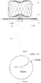
Fig. 8(a) is a schematic top view of an ablation member of an occluding system of Embodiment 3; -
Fig. 8(b) is a schematic side view of the ablation member of the occluding system shown inFig. 8(a) ; -
Fig. 9 is a partial structural schematic view of the occluding system of Embodiment 3; -
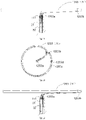
Fig. 10 is a top view of one structure of an ablation portion in an occluding system of Embodiment 5 after being unfolded; -
Fig. 11 is a schematic view of the ablation portion inFig. 10 connected to a catheter portion by a proximal connector; -
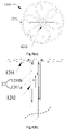
Fig. 12 is a top view of another structure of the ablation portion in the occluding system of Embodiment 5 after being unfolded; and -
Fig. 13 is a schematic view of the ablation portion inFig. 12 connected to a catheter portion by a proximal connector. - In order to facilitate the understanding of the embodiments, the embodiments will be described more comprehensively below with reference to relevant drawings. Various implementations of the embodiments are given in the drawings. However, the embodiments may be implemented in many different forms, and are not limited to the implementations described herein. Conversely, these implementations are provided so that the embodiments herein are understood more thoroughly and comprehensively.
- It should be noted that when an element is referred to as being "fixed" or "arranged" to another element, it may be directly on another element or centered elements may also be present. When an element is referred to as being "connected" to another element, it may be directly connected to another element or centered elements may also be present. The terms "vertical", "horizontal", "left", "right" and the like as used herein are for illustrative purposes only and are not meant to be the only implementations.
- Unless defined otherwise, all technical and scientific terms used herein have the same meaning as commonly understood by those skilled in the art to which the disclosure belongs. The terms used herein are for the purpose of describing implementations only and are not intended to be limiting. The term "and/or" as used herein includes any and all combinations of one or more of the associated listed items.
- In the field of interventional medical instruments, an end of a medical instrument implanted in a human or animal body that is closer to an operator is generally referred to as a "proximal end", an end that is further away from the operator is referred to as a "distal end", and the "proximal end" and "distal end" of any component of the medical instrument are defined in accordance with this principle. A position where a left atrium enters an LAA is defined as an ostium of the LAA and a position in the LAA adjacent to an entrance to the LAA is defined as a neck of the LAA. An "axial direction" generally refers to a longitudinal direction of the medical instrument when being delivered, and a "radial direction" generally refers to a direction of the medical instrument perpendicular to the "axial direction" thereof, and the "axial direction" and "radial direction" of any component of the medical instrument are defined in accordance with this principle.
-
Fig. 1 shows a schematic view of an occluding system according to the disclosure after anLAA occluder 10 is implanted into anLAA 101. Referring toFig. 1 , the occluding system includes theLAA occluder 10, a freezing device, a pushingtube 21, adelivery sheath 22, and anablation member 30 having anablation portion 31. - The
LAA occluder 10 includes a sealingportion 11 and a fixingportion 12 connected to the sealingportion 11. The sealingportion 11 and the fixingportion 12 may be connected directly or through an intermediate member. The sealingportion 11 may have a disc-like, columnar or plug-like structure, which is not limited herein. The sealingportion 11 is internally hollow and has an opening at a proximal end so that theablation portion 31 of theablation member 30 is inserted into asealing disc 10 from the opening. The shape of the fixingportion 12 is not limited and may be a column shape or an umbrella shape. - With continued reference to
Fig. 1 , the pushingtube 21 is movably arranged in thedelivery sheath 22 and detachably connected to the proximal end of the sealingportion 11 so that theLAA occluder 10 can be released from a distal end of thedelivery sheath 22 by manipulating the relative movement between the pushingtube 21 and thedelivery sheath 22. For example, in some implementations, when theLAA occluder 10 is pushed to the vicinity of theLAA 101 under the delivery of the pushingtube 21 and thedelivery sheath 22, thedelivery sheath 22 is withdrawn proximally relative to the pushingtube 21 so that theLAA occluder 10 connected to a distal end of the pushingtube 21 is exposed from a distal end of thedelivery sheath 22 and is self-expanded and released. - It should be noted that when the
LAA occluder 10 is implanted into theLAA 101, the fixingportion 12 is located in a cavity of theLAA 101 and closely attached to a cavity wall of theLAA 101 to prevent theLAA occluder 10 from falling out of theLAA 101. The sealingportion 11 occludes the ostium of theLAA 101, prevents thrombus formed in the cavity of the LAA from flowing into a left atrium, and prevents blood flow from the left atrium into the cavity of theLAA 101. - In the occluding system provided by the disclosure, the freezing device is connected to the
ablation member 30 for providing cryogen to theablation portion 31 of theablation member 30. In a delivery state, theablation member 30 is accommodated with theLAA occluder 10 in thedelivery sheath 21, and theablation portion 31 is accommodated in the sealingportion 11, so that theablation member 30 can be delivered to theLAA 101 together with theLAA occluder 10. After theLAA occluder 10 is unfolded in theLAA 101, theablation portion 31 located in the sealingportion 11 freezes the LAA in cooperation with cryogen so as to form an annular isolation band on the inner wall of theLAA 101. The annular isolation band is configured to block the conduction of electrical signals between theLAA 101 and the left atrium, thereby achieving electrical isolation between theLAA 101 and the left atrium, achieving the effect of electrical isolation, and enabling a patient to enjoy the benefits of long-term maintenance of sinus rhythm after the electrical isolation of theLAA 101. - In addition, in such a manner that occlusion and ablation are achieved by the
ablation member 30 being delivered to theLAA 101 together with theLAA occluder 10, that is, after theLAA occluder 10 is released in theLAA 101, the sealingportion 11 occludes the ostium of theLAA 101. Since theablation portion 31 of theablation member 30 is located in the sealingportion 11, theablation portion 31 will perform cryoablation on the inner wall of theLAA 101 in cooperation with the cryogen injected therein. And theablation portion 31 circumferentially abuts against the inner wall of theLAA 101 to be annular or nearly annular after being unfolded, thereby forming an annular isolation band on the inner wall of theLAA 101 under the action of cryogen. Therefore, the occluding system of the disclosure can occlude theLAA 101 by using theLAA occluder 10 while annularly freezing the inner wall of theLAA 101 by inflating theablation portion 31 with cryogen, so as to achieve the electrical isolation between theLAA 101 and the left atrium and the dual assurance of occlusion and ablation, thereby further preventing a patient from having a stroke. - For convenience in further describing the structure of the
LAA occluder 10 as shown inFig. 2 , taking a disc-shapedsealing portion 11 as an example, the surface of a side where the proximal end of the sealingportion 11 is located is referred to as a "proximal disc surface 11a", and accordingly, the surface of a side where the distal end of the sealingportion 11 is located is referred to as a "distal disc surface 11b". At least one flow blocking membrane (not shown) is arranged inside or outside the fixingportion 12, so as to achieve multiple occlusions in cooperation with the sealingportion 11 and improve the occlusion performance of theLAA 101. At least one flow blocking membrane is arranged on the sealingportion 11. For example, theproximal disc surface 11a and/or thedistal disc surface 11b are covered with a flow blocking membrane. As shown inFig. 2 , at least oneflow blocking membrane 13 is arranged inside the sealingportion 11 for preventing the circulation of blood from the left atrium into theLAA 101, so as to ensure that the ostium of theLAA 101 is tightly occluded. - In this embodiment, when the
ablation portion 31 of theablation member 30 is inserted into the sealingportion 11, theflow blocking membrane 13 is located on a side where the distal end of theablation portion 31 is located, so as to ensure that the occlusion effect of theflow blocking membrane 13 is not disturbed by theablation member 30. For example, theflow blocking membrane 13 of the sealingportion 11 is arranged between theproximal disc surface 11a and thedistal disc surface 11b, and theflow blocking membrane 13 is located between theablation portion 31 and thedistal disc surface 11b, so that a good occlusion effect of theflow blocking membrane 13 can be maintained while achieving ablation. - The size of the
flow blocking membrane 13 on the sealingportion 11 is equivalent to the size of a disc surface of the sealingportion 11, so that theflow blocking membrane 13 can completely cover the disc surface of the sealingportion 11 to achieve tight occlusion. For example, when theflow blocking membrane 13 and the sealingportion 11 are both regularly circular, the diameter of theflow blocking membrane 13 is equal to or less different from the diameter of the sealingportion 11. Theflow blocking membrane 13 is a polymer material, preferably polytetrafluoroethylene (PTFE) or polyethylene terephthalate (PET). - In some embodiments, the sealing
portion 11 is formed into a disc-shaped structure by heat treatment using a woven mesh tube structure. An edge of theflow blocking membrane 13 is fixed onto a woven wire of the sealingportion 11 by means of suturing or bonding, and the manner of fixing theflow blocking membrane 13 to the sealingportion 11 is not limited herein. - It should be noted that most of
LAA occluders 10 adopt the structures of filling in theLAA 101 and sealing the ostium of theLAA 101, including a plug structure form and a double-disc structure. - In the occluding system in the embodiments, the
LAA occluder 10 includes both split and integrally formed structures. It may be appreciated that a portion of the integrally formedLAA occluder 10 for occlusion may be regarded as the sealingportion 11 in the embodiments, and a portion thereof for fixing theLAA occluder 10 may be regarded as the fixingportion 12 in the embodiments. The sealingportion 11 and the fixingportion 12 in theLAA occluder 10 may also be integrally provided. For example, thewhole LAA occluder 10 is cylindrical, a portion of the proximal disc surface thereof for occlusion is equivalent to the sealingportion 11 in the disclosure, and a side wall portion thereof is configured to fix theLAA occluder 10 in the cavity of the LAA, thus being equivalent to the fixingportion 12 in the embodiments. - Embodiments will now be further described by taking a split-type double-disc structure of the
LAA occluder 10 as an example. - As shown in
Fig. 3 , theablation portion 31 of theablation member 30 is aballoon 311 having anopen end 311a. Theballoon 311 is arranged in the sealingportion 11. For example, in an embodiment where the sealingportion 11 includes aproximal disc surface 11a and adistal disc surface 11b, theballoon 311 is located between theproximal disc surface 11a and thedistal disc surface 11b of the sealingportion 11. - The
open end 311a of theballoon 311 is sleeved on the proximal end of the sealingportion 11, and connected with a proximal end opening of the sealingportion 11. The proximal end opening of the sealingportion 11 may be a through hole structure provided at the proximal end of the sealingportion 11 or may be a tube arranged at the proximal end of the sealingportion 11 and connected with the interior of the sealingportion 11. The structure and shape of the proximal end opening of the sealingportion 11 are not limited herein, and it is only sufficient to enable cryogen to be injected into theballoon 311 by means of a catheter. - For example, in some embodiments, as shown in
Fig. 3 , the proximal end of the sealingportion 11 is provided with aproximal connector 111. Theproximal connector 111 is in the shape of a hollow tube. Specifically, theproximal connector 111 has atube hole 111a so that thetube hole 111a of theproximal connector 111 constitutes the proximal opening of the sealingportion 11. - In this embodiment, the
open end 311a of theballoon 311 is sleeved on theproximal connector 111, and theopen end 311a of theballoon 311 is connected with a cavity of theproximal connector 111. Thus, the interior of theballoon 311 is connected with thetube hole 111a of theproximal connector 111, so that theballoon 311 may be inflated with cryogen such as N2O from thetube hole 111a. The connection and fixing mode between theballoon 311 and theproximal connector 111 is not limited, such as glue bonding or clamp connection. Using cryogen injected into theballoon 311, theinflated balloon 311 abuts, at least circumferentially, against the inner wall of theLAA 101, so as to form an annular freezing region at the neck or ostium of theLAA 101. After myocardial tissues at the freezing region are damaged by freezing, an annular isolation band is formed on the inner wall of theLAA 101, so as to use the annular isolation band to block the conduction of electrical signals between theLAA 101 and the left atrium, thereby achieving cryoablation. - With this structural arrangement, when the
LAA 101 is occluded by theLAA occluder 10, the ablation may be achieved by injecting cryogen through theballoon 311 arranged therein, so that the occlusion and ablation of theLAA 101 can be completed in one operation, thereby reducing the difficulty of operation, shortening the operation time, reducing the cost, and greatly reducing the probability of stroke of the patient. In addition, since the electrical isolation between theLAA 101 and the left atrium can be achieved while theLAA 101 is occluded, a patient can maintain sinus rhythm for a long time without the risk of cerebrovascular blockage or the like due to the fall-out of thrombus in theLAA 101. - The
balloon 311 may be made of a compliant material, such as a polyamide and polyether block copolymer. Polyamides are aliphatic, such asnylon 12,nylon 11, nylon 9, nylon 6, nylon 6/12, nylon 6/11, nylon 6/9, and nylon 6/6. Polyether blocks may be selected from polyoxytetramethylene glycol, tetramethylene ether, polyethylene glycol or polypropylene glycol. Due to the good compliance of theballoon 311, the accommodation of theballoon 311 in the sealingportion 11 during delivery does not affect the size selection of thedelivery sheath 22, and theballoon 311 can be rapidly expanded after being injected with cryogen, and can sufficiently abut against the circumferential edge of the sealingportion 11 when being inflated to a certain extent, so that an annular isolation band can be formed on the inner wall of theLAA 101 by means of the cryogen, thereby achieving the electrical isolation between theLAA 101 and the left atrium. - Thus, the shape of the
balloon 311 may be changed accordingly according to the degree of inflation of theballoon 311, so as to match the traction of the fixingportion 12 on the sealingportion 11 and enhance the fitting degree between the sealingportion 11 and the ostium of theLAA 101, thereby improving the stability and occlusion performance of theLAA occluder 10. - In an embodiment where the
flow blocking membrane 13 is arranged in the sealingportion 11, theflow blocking membrane 13 of the sealingportion 11 may be arranged between theproximal disc surface 11a and thedistal disc surface 11b, and theflow blocking membrane 13 is located between theballoon 311 and thedistal disc surface 11b, namely, theballoon 311 is located on a side where the proximal end of theflow blocking membrane 13 is located, so as to ensure that the occlusion effect of theflow blocking membrane 13 is not disturbed by theballoon 311. - Referring to
Figs. 1 and4(a) , in the occluding system provided by the embodiments, theablation member 30 further includes acatheter portion 32 connected directly or indirectly to theablation portion 31, and a proximal end of thecatheter portion 32 is connected to the freezing device for delivering cryogen to theballoon 311. The sealingportion 11 is in a compressed state when being accommodated in thedelivery sheath 22, and the ablation portion 31 (i.e., the balloon 311) is folded and accommodated in the sealingportion 11. Theballoon 311, after being unfolded in the sealingportion 11, abuts at least against the circumferential edge of the sealingportion 11 to better perform cryoablation on theLAA 101. - It should be noted that the
catheter portion 32 may be formed by a pushingtube 21 that is internally hollow or may be formed by a tube independent of the pushingtube 21. The structure of the occluding system will be further described below for each of these two cases respectively. - In some embodiments, the pushing
tube 21 is connected to the proximal end of the sealingportion 11 to not only push theLAA occluder 10 into theLAA 101, but meanwhile, a cavity of the pushingtube 21 is connected with the proximal end opening of the sealingportion 11 for injecting cryogen into theballoon 311 located in the sealingportion 11 through the pushingtube 21. Further, an embolic agent may be injected into theballoon 311 after cryoablation through the pushingtube 21, so as to realize multiple occlusions after inflating theballoon 311, so as to improve the sealing performance of the sealingportion 11. - With reference to
Fig. 4(a) , in an embodiment where the proximal end of the sealingportion 11 is provided with theproximal connector 111, the distal end of the pushingtube 21 is detachably connected to theproximal connector 111, so that the cavity of the pushingtube 21 is communicated with thetube hole 111a of theproximal connector 111. Thus, the pushingtube 21 can not only be used for pushing theLAA occluder 10 to satisfy the delivery requirements of theLAA occluder 10 and theballoon 311, and the pushingtube 21 can also serve as thecatheter portion 32 of theablation member 30 to satisfy the injection of cryogen into theballoon 311 to freeze theLAA 101. - In this embodiment, after the pushing
tube 21 is connected to theproximal connector 111, theLAA occluder 10 is accommodated together with the pushingtube 21 in thedelivery sheath 22 and delivered to theLAA 101 in a body. After theLAA occluder 10 is released in theLAA 101, theproximal connector 111 and the pushingtube 21 are not disconnected first. Under the situation that the proximal end of the pushingtube 21 is connected to the freezing device, cryogen delivered via the pushingtube 21 may be injected into theballoon 311 using thetube hole 111a of theproximal connector 111, so that the cooperation of theproximal connector 111 and the pushingtube 21 can not only meet the need for delivery of theLAA occluder 10, but also meet the need for injecting cryogen into theballoon 311 for cryoablation, reduce the number of tubes required for delivery of theLAA occluder 10, and meet the demand for a small overall tube diameter of an assembly for delivery. After cryoablation, theproximal connector 111 is disconnected from the pushingtube 21, and the pushingtube 21 and thedelivery sheath 22 are withdrawn from the body. - There are several possible structures for the connection of the pushing
tube 21 to theproximal connector 111. For example, in some embodiments, thetube hole 111a of theproximal connector 111 may be a threaded hole, and the distal end of the pushingtube 21 is in threaded fit with thetube hole 111a of theproximal connector 111. In other embodiments, the distal end of the pushingtube 21 is connected to theproximal connector 111 through a buckle. In other implementations, the pushingtube 21 may be connected to theproximal connector 111 by other means, so long as they are connected, for example to provide communication with the interior of theballoon 311 through a cavity of the pushingtube 21 to meet the need to inject cryogen into theballoon 311. - In other embodiments, the occluding system may include two internally hollow catheters. One of the catheters is the pushing
tube 21. The distal end of the catheter is detachably connected to theproximal connector 111 for pushing theLAA occluder 10. The other catheter is configured to inflate theballoon 311 with cryogen to achieve cryoablation of theLAA 101. - For convenience of description, one of the catheters is referred to as a
first catheter 21a and the other catheter is referred to as a second catheter 21b. The "second catheter 21b is also the pushingtube 21. In some embodiments, thefirst catheter 21a is sleeved inside the second catheter 21b, and they are axially movable relative to each other. In other embodiments, thefirst catheter 21a and the second catheter 21b are not sleeved together, and thefirst catheter 21a and the second catheter 21b may have the same or different diameters. - Specifically, as shown in
Fig. 4(b) , theablation member 30 further includes acatheter portion 32. Thecatheter portion 32 includes afirst catheter 21a. Thefirst catheter 21a is an internally hollow tubular body. The outer diameter of thefirst catheter 21a is smaller than the inner diameter of the second catheter 21b. Thefirst catheter 21a is sheathed inside the second catheter 21b, and thefirst catheter 21a is axially movable in a cavity of the second catheter 21b. A distal end of the second catheter 21b is detachably connected to theproximal connector 111, a distal end of thefirst catheter 21a extends into theproximal connector 111, and a cavity of thefirst catheter 21a is connected with thetube hole 111a of theproximal connector 111. The distal end of thefirst catheter 21a may abut in theproximal connector 111 or may be detachably connected to theproximal connector 111. For example, the distal end of the second catheter 21b may be detachably connected to theproximal connector 111 through an external thread provided on the outer wall of theproximal connector 111, and the distal end of thefirst catheter 21a may be detachably connected to theproximal connector 111 through an internal thread provided on the inner wall of theproximal connector 111. During delivery, both thefirst catheter 21a and the second catheter 21b are delivered to theLAA 101 together with theLAA occluder 10. After theLAA occluder 10 is released, cryoablation is performed by injecting cryogen into theballoon 311 in the sealingportion 11 through thefirst catheter 21a. After cryoablation, theproximal connector 111 is disconnected from thefirst catheter 21a and the second catheter 21b, and thefirst catheter 21a, the second catheter 21b and thedelivery sheath 22 are withdrawn from the body. - In other embodiments, only the second catheter 21b is connected to the
proximal connector 111 and delivered to theLAA 101 along with theLAA occluder 10 during the delivery of theLAA occluder 10. When it is required to perform cryoablation on theLAA 101 after theLAA occluder 10 is unfolded at theLAA 101, thefirst catheter 21a may be pushed along the cavity of the second catheter 21b, and then thefirst catheter 21a may be connected to theproximal connector 111, so that the cavity of thefirst catheter 21a is connected with the interior of theballoon 311, and then the cryogen may be injected into theballoon 311 through thefirst catheter 21a to achieve cryoablation on theLAA 101. The cryoablation is simple in operation and high in safety. After the ablation is completed, thefirst catheter 21a and the second catheter 21b may be disconnected from theproximal connector 111 after the cryogen is withdrawn from the body, and thefirst catheter 21a and the second catheter 21b may be withdrawn from the body together with thedelivery sheath 22. - It should be noted that the manner in which the
first catheter 21a and the second catheter 21b are used in cooperation for the delivery and cryoablation of theLAA occluder 10 is not limited to the above-described exemplary case. For example, in other implementations, after theLAA occluder 10 is unfolded at theLAA 101, cryoablation is performed on theLAA 101 by injecting cryogen into theballoon 311 through thefirst catheter 21a. Then, thefirst catheter 21a is withdrawn again, and the embolic agent is delivered into theballoon 311 through the second catheter 21b, so as to fill the interior of the sealingportion 11 after theballoon 311 is inflated, thereby achieving the re-occlusion of the neck or ostium of theLAA 101. Multiple occlusions can improve the sealing performance of the sealingportion 11. In other embodiments, the pushingtube 21 is another hollow tube than the second tube 21b described above, and thecatheter portion 32 includes afirst catheter 21a and a second catheter 21b. In contrast to the above, thefirst catheter 21a is withdrawn after cryoablation is performed, and then the second catheter 21b is delivered along the cavity of thedelivery sheath 22 to theLAA 101 and connected to theproximal connector 111 of theLAA occluder 10. Then, the embolic agent is injected into theballoon 311 through the second catheter 21b. The pushingtube 21 may be continuously connected to theproximal connector 111 when it is necessary to inject the embolic agent or may be withdrawn from the body together with thefirst catheter 21a when thefirst catheter 21a is withdrawn. - Further, in some embodiments, a distal end of the
first catheter 21a has a tapered section (not shown), and an inner diameter of a distal end of the tapered section is smaller than an inner diameter of a proximal end of the tapered section. Thus, the distal end of the tapered section has a microporous structure, and theballoon 311 is inflated with cryogen by using micropores, so that the Joule-Thomson principle may be used, that is, when gas is injected from a higher pressure region into a lower pressure region through a narrow micropore, it will be throttled, and the temperature of most of the gas will suddenly decrease after throttling, thereby enhancing the freezing effect of the cryogen. - The manner of connection between the
first catheter 21a and theproximal connector 111 and the manner of connection between the second catheter 21b and theproximal connector 111 may be a detachable connection manner such as threaded or locking connection, which is not limited herein. - Similar to
Embodiment 1, in an occluding system of Embodiment 2, the pushingtube 21 is movably arranged in thedelivery sheath 22 and can be detachably connected to the proximal end of the sealingportion 11 of theLAA occluder 10, so as to push theLAA occluder 10 into a distal tube section of thedelivery sheath 22 or push out from the distal end of thedelivery sheath 22 to release theLAA occluder 10. The same points or similarities between Embodiment 2 andEmbodiment 1 will not be described in detail herein, and the main difference therebetween is that, as shown inFigs. 5 and6 , in the occluding system of Embodiment 2, theballoon 311 constituting theablation portion 31 is annular, which is fixedly sleeved on the distal end of thecatheter portion 23, and the interior of theballoon 311 is communicated with the interior of thecatheter portion 23. Theballoon 311 and thecatheter portion 23 form a balloon catheter together. - In this embodiment, in a delivery state, the distal end of the
catheter portion 23 passes through the proximal end opening of the sealingportion 11, so that theballoon 311, sleeved at the distal end of thecatheter portion 23, is located in the sealingportion 11 of theLAA occluder 10. Therefore, after theLAA occluder 10 is unfolded in theLAA 101, the freezing device delivers cryogen into theballoon 311 through thecatheter portion 23. Theballoon 311 freezes the neck or ostium of theLAA 101 in cooperation with the cryogen therein, so that after myocardial tissues at a freezing region are damaged, an annular isolation band is formed, so as to use the annular isolation band to block the conduction of electrical signals between theLAA 101 and the left atrium, thereby achieving cryoablation. - The balloon catheter is arranged in the cavity of the pushing
tube 21, and the distal end of thecatheter portion 23 is provided with an inflation/deflation port 23a. Theballoon 311 is arranged at the distal end of thecatheter portion 23, and the interior of theballoon 311 is connected with the inflation/deflation port 23a. Thecatheter portion 23 can inject cryogen into theballoon 311 through the inflation/deflation port 23a to meet the need for cryoablation of the neck or ostium of theLAA 101. - Referring to
Fig. 7 , the inflation/deflation port 23a may be at least one throughhole 23b formed in the sidewall of the distal end of thecatheter portion 23. Theballoon 311 is sleeved at a position of thecatheter portion 23 where the throughhole 23b is formed to communicate with the cavity of thecatheter portion 23 through the throughhole 23b, so that cryogen may be injected into theballoon 311 through thecatheter portion 23. - In some embodiments, the inflation/
deflation port 23a includes a plurality of throughholes 23b, for example, two or more throughholes 23b, and the plurality of throughholes 23b are evenly provided along the circumferential side of thecatheter portion 23, so that when thecatheter portion 23 inflates theballoon 311 with cryogen through the inflation/deflation port 23a, theballoon 311 can be evenly expanded, thereby avoiding biasing to one side in the sealingportion 11 due to too quick or slow local expansion. The even inflation of theballoon 311 in the sealingportion 11 ensures that the cryogen in theballoon 311 evenly freezes the freezing region of theLAA 101 to obtain a better cryoablation effect. - The shape of the through
hole 23b may be circular, square or elongated, which is not limited therein. Only when theballoon 311 is arranged at the position of thecatheter portion 23 where the throughhole 23b is formed, the throughhole 23b can be sufficient to inflate theballoon 311 with cryogen through the cavity of thecatheter portion 23. - In some implementations, after the
LAA occluder 10 is connected to the distal end of the pushingtube 21, theLAA occluder 10 and the pushingtube 21 are accommodated together in the cavity of thedelivery sheath 22 and delivered to theLAA 101 via thedelivery sheath 22. After theLAA occluder 10 is unfolded, the balloon catheter extends from the proximal end of the pushingtube 21 into the cavity of the pushingtube 21 and delivered to the position of theLAA occluder 10 until theballoon 311 on the balloon catheter is inserted into the sealingportion 11 after passing through thetube hole 111a of theproximal connector 111. Thecatheter portion 23 of the balloon catheter is connected to theproximal connector 111 through threads or buckles. The proximal end of thecatheter portion 23 is connected to the freezing device. After cryogen is injected into theballoon 311 through thecatheter portion 23, theballoon 311 is expanded and unfolded in the sealingportion 11. The cryogen in theballoon 311 is capable of cryoablation of the neck or ostium of theLAA 101. In other implementations, the pushingtube 21 may be the balloon catheter as described above, and after the balloon catheter is connected to theproximal connector 111, thecatheter portion 23 may function both to push theLAA occluder 10 and to deliver cryogen to theablation portion 31. - In other embodiments, the
balloon 311 of the non-inflated balloon catheter may be pre-inserted in the sealingportion 11 so that the balloon catheter is delivered into theLAA 101 with the aid of the pushingtube 21 and thedelivery sheath 22 together with theLAA occluder 10. Cryoablation of the neck or ostium of theLAA 101 can also be achieved by injecting cryogen into thecatheter portion 23 through the freezing device and delivering the cryogen into theballoon 311 via thecatheter portion 23 after the sealingportion 11 is unfolded in theLAA 101. - Referring again to
Fig. 6 , thetube hole 111a of theproximal connector 111 on the sealingportion 11 allows the passage of the distal end of the non-inflated balloon catheter. In an example, the balloon catheter is axially movably arranged in an inner cavity of the pushingtube 21, and the distal end of the balloon catheter enables theballoon 311 to extend into the sealingportion 11 from thetube hole 111a when theballoon 311 is in a non-inflated, i.e., deflated state. With this structural arrangement, it is possible to flexibly insert theballoon 311 in the sealingportion 11 when cryoablation of theLAA 101 is required and remove theballoon 311 from the sealingportion 11 after the cryoablation operation is completed. This operation manner is convenient, safe and reliable, and provides less structural improvement to theLAA occluder 10. - The mechanism of action of the balloon catheter in cooperation with the
LAA occluder 10 for cryoablation will be further described below with the example of injecting N2O into theballoon 311. - First, during implantation of the
LAA occluder 10, theballoon 311 at the distal end of the balloon catheter is in a non-inflated state in which the portion of the balloon catheter where theballoon 311 is arranged is placed in the sealingportion 11 of theLAA occluder 10 and the balloon catheter is connected to theproximal connector 111 of the sealingportion 11. The balloon catheter is then delivered to theLAA 101 along with theLAA occluder 10. When theLAA occluder 10 is unfolded at theLAA 101, that is, the sealingportion 11 is self-expanded and unfolded, and occludes the ostium of theLAA 101, theballoon 311 is located between theproximal disc surface 11a and thedistal disc surface 11b of the sealingportion 11. - Then, after the freezing device is connected to the proximal end of the balloon catheter, cryogen N2O is injected into the
balloon 311 through thecatheter portion 23. Theballoon 311 will be gradually inflated by the cryogen N2O and expanded between theproximal disc surface 11a and thedistal disc surface 11b of the sealingportion 11. Then, the outer wall of theballoon 311 will gradually approach an inner wall near the ostium or ostium of theLAA 101, and under the action of the cryogen N2O, myocardial cells around the ostium or ostium of theLAA 101 will be necrosed due to the sudden temperature decrease, so as to form an annular isolation band. Thus, the transmission of abnormal electrical signals between theLAA 101 and the left atrium is interrupted to achieve the effect of electrical isolation between theLAA 101 and the left atrium. - Additionally, after the freezing of the cells around the ostium or neck of the
LAA 101 with the cryogen N2O is completed, the cryogen N2O in theballoon 311 is withdrawn with the balloon catheter, so that the volume of theballoon 311 is reduced until theballoon 311 may be withdrawn proximally together with thecatheter portion 23 to continue withdrawing proximally and eventually out of the body after passing through theproximal connector 111. - It should be noted that the balloon catheter is connected with the
balloon 311 through the inflation/deflation port 23a at the distal end of thecatheter portion 23. As a result, when the cryogen N2O is injected into theballoon 311 through thecatheter portion 23, liquid cryogen discharged from the interior of the freezing device is sprayed into theballoon 311 through thecatheter portion 23 and the inflation/deflation port 23a is rapidly gasified, and the gasified cryogen N2O rapidly inflates theballoon 311. When the liquid cryogen N2O is sprayed towards the interior of theballoon 311 and gasified, the temperature of myocardial tissues in contact with theballoon 311 rapidly decreases due to heat absorbed by surrounding tissues by the gasification of the liquid cryogen N2O. For example, the temperature of the myocardial tissues stably decreases to be below -30°C. In this way, since the myocardial cells in the ostium or neck of theLAA 101 are gasified and frozen by the cryogen N2O, the temperature rapidly decreases (hereinafter, referred to as "freezing stage"), and after theballoon 311 is withdrawn with thecatheter portion 23, the temperature of a frozen part of the ostium or neck of theLAA 101 gradually rises (hereinafter, referred to as "warming stage"). During the freezing stage, ice crystals are formed in the myocardial tissues, which lead to dehydration and necrosis of myocardial cells and destruction of cell structures. However, during the warming stage, the ice crystals melt, resulting in the blockage of micro-circulation and secondary damage, and eventually irreversible damage to the myocardial tissues, thus forming an annular isolation band on the inner wall of theLAA 101, preventing the transmission of abnormal electrical signals from theLAA 101 to the left atrium, and achieving an electrical isolation effect. - The same points or similarities between Embodiment 3 and Embodiment 2 will not be described in detail herein, and the main difference therebetween is that the
ablation portion 31 in Embodiment 2 is aballoon 311 made of high molecular material, while theablation portion 31 in Embodiment 3 is a plurality of bent tubes made of metal. As shown inFigs. 8(a), 8(b) and9 , theablation member 1200 used in this embodiment is in cooperation with theLAA occluder 10 to ablate the inner wall of theLAA 101, thereby achieving electrical isolation between theLAA 101 and the left atrium. During implantation of theLAA occluder 10, theablation portion 31 of theablation member 1200 is folded and accommodated in the sealingportion 11, and theablation member 1200 is delivered to theLAA 101 together with theLAA occluder 10. Theablation member 1200 includes anablation portion 31 and acatheter portion 32, theablation portion 31 is connected to thecatheter portion 32, and theablation portion 31 is located at the distal end of thecatheter portion 32. The freezing device can deliver cryogen to theablation portion 31 through thecatheter portion 32. Theablation member 1200 and the sealingportion 11 are arranged independently of each other, and after the ablation is completed, theablation member 1200 may be entirely withdrawn from the body. - The
ablation member 1200 has some elastic deformability, i.e., can be compressed and self-expanded and unfolded, so that theablation member 1200 can be accommodated in thedelivery sheath 22 in an elongated shape. Theablation portion 31 of theablation member 1200 may be folded and accommodated in thedelivery sheath 22 so that, upon release of theablation member 1200 from thedelivery sheath 22, theablation portion 31 of theablation member 1200 is automatically unfolded, such as in the form shown inFigs. 8(a) and 8(b) . - The
ablation member 1200 may be made of high molecular material with good resilience, and the high molecular material may be selected from one or more of a group consisting of PET, poly-L-lactide acid (PLA), poly-glycolide (PGA), polyhydroxyalkanoate (PHA), poly-dioxanone (PDO), and poly-caprolactone (PCL). - In some embodiments, the
ablation member 1200 may be made of an elastic alloy tube, such as a nitinol tube. Theablation member 1200 may be made of a high molecular tube wrapped with an elastic spring tube, and the high molecular tube may be wrapped outside the spring tube or may be embedded in the spring tube, which is not limited herein. - As shown in
Figs. 8(a) and 8(b) , theablation portion 31 of theablation member 1200 includes a plurality ofbent tubes 1201. Thebent tubes 1201 fit to form a disc shape so that theablation portion 31 is maximally radially unfolded during unfolding. Thus, the edge of theablation portion 31 abuts against the inner wall of theLAA 101, thereby ensuring the ablation effect. - The
ablation member 1200 may adopt the Joule-Thomson principle, that is, when gas is injected from a higher pressure region into a lower pressure region through a narrow micropore, it will be throttled. The temperature of most of the gas will suddenly decrease after throttling. For example, in some embodiments, local cryoablation of the inner wall of theLAA 101 is performed by injecting gas into thebent tubes 1201 of theablation member 1200 through micropores at the distal end of a gas delivery tube (not shown) connected to theablation portion 31 to make the temperature around thebent tubes 1201 suddenly decrease. - With reference to
Figs. 8(a) and 8(b) , thecatheter portion 32 of theablation member 1200 includes a plurality ofgas inlet tubes 1201a andgas outlet tubes 1201b axially arranged. Onegas inlet tube 1201a and onegas outlet tube 1201b are connected to both ends of onebent tube 1201, respectively. The freezing device feeds freezing gas into thebent tube 1201 through thegas inlet tube 1201a, so that during the flow of the freezing gas through thebent tube 1201, local cryoablation is performed on the inner wall of theLAA 101 in contact with thebent tube 1201, and then the gas in thebent tube 1201 is discharged from the body through thegas outlet tube 1201b. - The
bent tube 1201, thegas inlet tube 1201a and thegas outlet tube 1201b may be an integrated structure formed by heat-setting a single tube, or after forming thebent tube 1201, thegas inlet tube 1201a and thegas outlet tube 1201b, respectively, thegas inlet tube 1201a and thegas outlet tube 1201b are connected to both ends of thebent tube 1201, and thegas inlet tube 1201a and thegas outlet tube 1201b are communicated with thebent tube 1201. - Further, the
bent tubes 1201 are petal-shaped. Referring to theablation member 1200 shown inFig. 8(a) , theablation portion 31 of theablation member 1200 includes sixbent tubes 1201. The sixbent tubes 1201 are evenly radially arranged around the central axis of the ablation member to form anablation portion 31 having six petallike structures without interfering with each other. Theablation portion 31 of this structure can rapidly perform cryoablation by means of the Joule-Thomson principle, and can ensure an ideal effect of freezing. - Referring to
Figs. 8(b) and9 , thegas inlet tube 1201a and thegas outlet tube 1201b communicated with thebent tube 1201 are tied together. Thus, thecatheter portion 32 formed by thegas inlet tube 1201a and thegas outlet tube 1201b is easily accommodated in the pushingtube 21. The plurality ofgas inlet tubes 1201a and the plurality ofgas outlet tubes 1201b may be tied together by means of asleeve 1202 to make the plurality ofgas inlet tubes 1201a and the plurality ofgas outlet tubes 1201b more compact and easily accommodated in the pushingtube 21. - In some embodiments, the plurality of
gas inlet tubes 1201a are arranged in the vicinity of the central axis of theablation member 1200, and the plurality ofgas outlet tubes 1201b are tubular along the central axis of theablation member 1200 and located outside the plurality ofgas inlet tubes 1201a. With this structural arrangement, the plurality ofgas inlet tubes 1201a and the plurality ofgas outlet tubes 1201b can be more compactly tied together, and it is convenient to centrally and simultaneously inject cryogen into the plurality ofgas inlet tubes 1201a. - Referring to
Fig. 9 , in an embodiment where theflow blocking membrane 13 is arranged in the sealingportion 11, a disc-shapedablation portion 31 formed by the plurality ofbent tubes 1201 may be pre-placed inside the sealingportion 11 and located on the side where the proximal end of theflow blocking membrane 13 is located, so as to maintain a good occlusion effect of theflow blocking membrane 13. - The
ablation portion 31 may be accommodated in the sealingportion 11 via thetube hole 111a of theproximal connector 111 of the sealingportion 11 after being folded. Theablation member 1200 is accommodated in thedelivery sheath 22 together with theLAA occluder 10 and delivered into theLAA 101. Upon release of theLAA occluder 10, thebent tubes 1201 are self-expanded and unfolded as the sealingportion 11 is released. The plurality ofbent tubes 1201 are formed in a disc shape after being unfolded, and the edges thereof abut against the ostium or neck of theLAA 101. Thus, when the freezing device delivers freezing gas into thebent tube 1201 through thegas inlet tube 1201a, the freezing gas in thebent tube 1201 freezes the inner wall of theLAA 101 in contact with or close to the edge of thebent tube 1201, so as to form an annular isolation band near the ostium or neck of theLAA 101, thereby blocking the conduction of electrical signals between theLAA 101 and the left atrium, achieving the electrical isolation. - The same points or similarities between Embodiment 4 and Embodiment 3 will not be described in detail herein, and the main difference therebetween is that the
ablation portion 31 including the plurality of petal-shapedbent tubes 1201 and thecatheter portion 32 are not integrally arranged, but are two separate assemblies. Thecatheter portion 32 in the present embodiment is a tubular member that is internally hollow, thereby simplifying the delivery process and reducing the difficulty of delivering an instrument through a curved vessel without significantly affecting the position where theLAA occluder 10 is released. - The
ablation portion 31 is fixedly connected to theproximal connector 111 of the sealingportion 11, and thecatheter portion 32 is detachably connected to theproximal connector 111. After being unfolded in the sealingportion 11, theablation portion 31 abuts against the circumferential edge of the sealingportion 11 and forms an annular isolation band on the inner wall of theLAA 101 after cryogen is injected. In an example, ends of eachbent tube 1201 are located in the cavity of theproximal connector 111. For example, respective first ends of the plurality ofbent tubes 1201 are arranged in the vicinity of the central axis of theproximal connector 111, and respective second ends of the plurality ofbent tubes 1201 are fixed onto the inner wall of theproximal connector 111. The first end of eachbent tube 1201 is communicated with the cavity of thecatheter portion 32, and the second end of eachbent tube 1201 is communicated with the cavity of the pushingtube 21, so that the freezing device may inject cryogen into eachbent tube 1201 through thecatheter portion 32 and via the respective first ends, the cryogen enters the cavity of the pushingtube 21 via the second end after passing through thebent tube 1201, and the cryogen is discharged from the body through the pushingtube 21. The first ends of the plurality ofbent tubes 1201 are gathered and fixed together by welding, clamping, binding or bonding. After the first ends of the plurality ofbent tubes 1201 are fixed together, an external thread may be provided on an outer surface of the proximal end thereof, and internal threads may be provided on the distal end of thecatheter portion 32, so that thecatheter portion 32 may be detachably connected to the proximal end of theablation portion 31 by means of threads. Since theablation portion 31 is fixedly connected to theproximal connector 111, the detachable connection between thecatheter portion 32 and theproximal connector 111 is achieved. - Further, the respective first ends of the plurality of
bent tubes 1201 are accommodated in a sleeve. That is, the respective first ends of the plurality ofbent tubes 1201 are fixed together by a sleeve. External threads may be provided on the sleeve, and internal threads may be provided on the distal end of thecatheter portion 32, whereby thecatheter portion 32 may be connected to the sleeve by means of threads to achieve the detachable connection between thecatheter portion 32 and the proximal end of theablation portion 31. Since theablation portion 31 is fixedly connected to theproximal connector 111, the detachable connection between thecatheter portion 32 and theproximal connector 111 is achieved. - During delivery of the
LAA occluder 10, thecatheter portion 32 may be connected to theproximal connector 111 of the sealingportion 11 and accommodated in the cavity of the pushingtube 21. After the pushingtube 21 and theproximal connector 111 are also connected, thecatheter portion 32 is delivered to theLAA 101 in thedelivery sheath 22 together with theLAA occluder 10. In another embodiment, rather than thecatheter portion 32 being delivered to theLAA 101 in thedelivery sheath 22 together with theLAA occluder 10, the distal end of thecatheter portion 32 extends from the proximal end of a delivery tube into the cavity of the delivery tube after theLAA occluder 10 is unfolded in theLAA 101, and thecatheter portion 32 is then delivered to theLAA 101 along the delivery tube. After the distal end of thecatheter portion 32 is connected to theproximal connector 111 and the freezing device is connected to the proximal end of thecatheter portion 32, the freezing device injects cryogen into theablation portion 31 through thecatheter portion 32. - The same points or similarities between Embodiment 5 and Embodiment 4 will not be described in detail herein, and the main difference therebetween is that, referring to
Figs. 10 and11 , in Embodiment 5, theablation portion 31 includes a double-cavitybent tube 1203, and thebent tube 1203 is annular after being unfolded and abuts against the circumferential edge of the sealingportion 11, so as to form an annular isolation band on the inner wall of theLAA 101 after injecting cryogen. Thefirst end portion 1203a of thebent tube 1203 has two openings, one of which is used to inject cryogen after being connected to thecatheter portion 32, and the other of which is used to discharge cryogen after flowing along thebent tube 1203. Theablation portion 31 includes only one bent tube, so that when theablation portion 31 is folded in the sealingportion 11, the outer diameter of the sealingportion 11 in a compressed state is not excessively increased, and it is more likely to fold. - In one implementation, a partition (not shown) extending along its length direction is arranged inside the
bent tube 1203, thereby dividing the interior of thebent tube 1203 into two cavities. With continued reference toFigs. 10 and11 , the two cavities of thebent tube 1203 are arranged side by side along the length direction of thebent tube 1203, thesecond end 1203b of thebent tube 1203 is closed, and the two cavities of thebent tube 1203 are communicated near thesecond end 1203b. Thefirst end 1203a of thebent tube 1203 is fixed onto the inner wall of theproximal connector 111. Internal threads may be provided at the position of a first opening of thebent tube 1203, external threads may be provided on thecatheter portion 32, and thecatheter portion 32 is in threaded connection with thefirst end 1203a of thebent tube 1203. Thesecond end 1203b of thebent tube 1203 may be a free end or may be fixed to the distal end of the sealingportion 11 as long as the total length of thebent tube 1203 is not greater than the length of the sealingportion 11 in a compressed state. Thesecond end 1203b of thebent tube 1203 is fixed to the distal end of the sealingportion 11, and when the sealingportion 11 needs to be accommodated in thedelivery sheath 22, thebent tube 1203 can be rapidly folded along with the compression of the sealingportion 11 without affecting the transition of the sealingportion 11 from an unfolded state to a compressed state. When the sealingportion 11 is accommodated in thedelivery sheath 22, thebent tube 1203 may be folded in an approximately straight line shape as the sealingportion 11 is compressed. - In an example, after the proximal end of the
catheter portion 32 is connected to the freezing device, the freezing device injects cryogen into the first opening of thefirst end 1203a of thebent tube 1203 through thecatheter portion 32. The cryogen moves from the first opening along one of the cavities of thebent tube 1203 towards thesecond end 1203b of thebent tube 1203 and enters the other cavity where the two cavities are communicated, then moves along thebent tube 1203 towards thefirst end 1203a of thebent tube 1203, is discharged from the second opening into the pushingtube 21, and is finally discharged from the body via the pushingtube 21. Arrows inFigs. 10 and11 indicate the moving direction of cryogen. - In another implementation, referring to
Figs. 12 and 13 , thebent tube 1203 includes a sleevedinner tube 1203c andouter tube 1203d, and theinner tube 1203c and theouter tube 1203d are connected by a partition (not shown). The interior of theinner tube 1203c is hollow and defines the first cavity ofbent tube 1203, and a cavity between theouter tube 1203d and theinner tube 1203c is the second cavity of thebent tube 1203. Referring toFig. 13 , at thefirst end 1203a of thebent tube 1203, internal threads are provided in theinner tube 1203c, and theinner tube 1203c may be detachably connected to thecatheter portion 32 by means of threads at thefirst end 1203a of thebent tube 1203. At thesecond end 1203b of thebent tube 1203, an end of theouter tube 1203d is closed and constitutes thesecond end 1203b of thebent tube 1203, and an end of theinner tube 1203c is located inside theouter tube 1203d, whereby the first cavity is communicated with the second cavity at thesecond end 1203b of thebent tube 1203. When theinner tube 1203c is connected to thecatheter portion 32, the cryogen injected into the first cavity through thecatheter portion 32 moves along theinner tube 1203c, enters the second cavity at thesecond end 1203b of thebent tube 1203, then moves along theouter tube 1203d towards thefirst end 1203a of thebent tube 1203, is discharged into the pushingtube 21 via an opening between theinner tube 1203c and theouter tube 1203d at thefirst end 1203a of thebent tube 1203, and is finally discharged from the body along the pushingtube 21. - In another embodiment, the
ablation portion 31 includes a single-cavity bent tube which is open at both ends, and the bent tube is annular after being unfolded and abuts against the circumferential edge of the sealingportion 11, so as to form an annular isolation band on the inner wall of theLAA 101 after injecting cryogen. The first end of the bent tube is located in the cavity of theproximal connector 111, may be suspended in the cavity of theproximal connector 111, or may be fixed onto the inner wall of theproximal connector 111. The second end of the bent tube is fixed onto the inner wall of theproximal connector 111. The first end of the bent tube may be detachably connected to the distal end of thecatheter portion 32 by means of threaded or clamping connection, etc. And after the proximal end of thecatheter portion 32 is connected to the freezing device, the freezing device injects cryogen into theablation portion 31, i.e. the bent tube, through thecatheter portion 32. The cryogen moves along the bent tube towards the second end thereof, is discharged through an opening at the second end into the pushingtube 21, and is finally discharged from the body via the pushingtube 21. - Each feature of the above-described embodiments can be combined in any combination, and in order to make the description concise, not all the possible combinations of each feature in the above-described embodiments are described. However, as long as there is no contradiction between the combinations of these features, they should be considered as within the scope of the embodiments.
- The above-described embodiments express only a few implementations, which are described in greater detail but should not be construed as limiting the scope. It will be appreciated by those of ordinary skill in the art that numerous variations and modifications may be made to the embodiments without departing from their scope.
Claims (20)
- A left atrial appendage (LAA) occluder, comprising:
a sealing portion, the sealing portion comprising an ablation portion arranged in the sealing portion, and a hollow proximal connector arranged at a proximal end of the sealing portion, wherein the ablation portion is connected to the proximal connector, the ablation portion is configured to freeze an LAA after being injected with cryogen so as to form an annular isolation band on an inner wall of the LAA, the annular isolation band is configured to block the conduction of electrical signals between the LAA and a left atrium, when the sealing portion is in a compressed state, the ablation portion is folded and accommodated in the sealing portion, and the ablation portion abuts against a circumferential edge of the sealing portion after being unfolded in the sealing portion. - The LAA occluder according to claim 1, wherein the ablation portion is a balloon having an open end sleeved on the proximal connector of the sealing portion and connected with a cavity of the proximal connector.
- The LAA occluder according to claim 1, wherein the ablation portion comprises a plurality of bent tubes, fitting to form a disc after being unfolded, ends of each of the bent tubes being located in the cavity of the proximal connector.
- The LAA occluder according to claim 3, wherein the bent tubes are petal-shaped and respectively comprise a first end and a second end, wherein the respective first ends of the plurality of bent tubes are arranged in the vicinity of a central axis of the proximal connector and the respective second ends of the plurality of bent tubes are fixed onto an inner wall of the proximal connector.
- The LAA occluder according to claim 4, wherein the respective first ends of the plurality of bent tubes are accommodated in a sleeve.
- The LAA occluder according to claim 1, wherein the ablation portion comprises a single-cavity or double-cavity bent tube which is unfolded to be annular and abuts against the circumferential edge of the sealing portion, at least one end of the bent tube being fixed onto the inner wall of the proximal connector.
- The LAA occluder according to claim 1, wherein at least one flow blocking membrane is arranged in the sealing portion and located on a side where a distal end of the ablation portion is located.
- The LAA occluder according to claim 1 further comprising a fixing portion, the sealing portion being located on one side of the fixing portion and connected to the fixing portion, or the sealing portion and the fixing portion being integrally arranged.
- An occluding system, characterized by comprising the left atrial appendage (LAA) occluder according to any one of claims 1 to 8, further comprising a pushing tube, a delivery sheath and a catheter portion, wherein the pushing tube is movably arranged in the delivery sheath and detachably connected to the proximal connector of the sealing portion, and the catheter portion is movably arranged in the pushing tube and detachably connected to the proximal connector.
- The occluding system according to claim 9, wherein the catheter portion is connected to the proximal connector during delivery of the LAA occluder; or, the catheter portion is delivered to the LAA and connected to the proximal connector after the LAA occluder is unfolded.
- An occluding system, comprising:
a left atrial appendage (LAA) occluder, a pushing tube, a delivery sheath, and an ablation member, wherein the LAA occluder comprises a sealing portion that is internally hollow and has an opening at a proximal end, the pushing tube is movably arranged in the delivery sheath and detachably connected to the proximal end of the sealing portion, the ablation member comprises an ablation portion, the ablation member is accommodated with the LAA occluder in the delivery sheath in a delivery state, the ablation portion is accommodated in the sealing portion, after the LAA occluder is unfolded in an LAA, the ablation portion is configured to freeze the LAA after being injected with cryogen so as to form an annular isolation band on an inner wall of the LAA, and the annular isolation band is configured to block the conduction of electrical signals between the LAA and a left atrium. - The occluding system according to claim 11, wherein the ablation member further comprises a catheter portion, one end of the catheter portion is connected to the ablation portion, the catheter portion is detachably connected to the proximal end of the sealing portion, and the interior of the catheter portion is communicated with the proximal end opening of the sealing portion.
- The occluding system according to claim 12, wherein the ablation portion is an annular balloon fixedly sleeved on a distal end of the catheter portion, the interior of the balloon being communicated with the interior of the catheter portion.
- The occluding system according to claim 12, wherein the pushing tube is internally hollow and the catheter portion is located in the pushing tube at least during ablation; or, the catheter portion is the pushing tube.
- The occluding system according to claim 12, wherein the ablation portion is a balloon having an open end, the open end of the balloon being sleeved on the proximal end of the sealing portion and communicated with the proximal end opening of the sealing portion.
- The occluding system according to claim 11, wherein the ablation portion abuts against a circumferential edge of the sealing portion after being unfolded in the sealing portion.
- The occluding system according to claim 11, wherein at least one flow blocking membrane is arranged in the sealing portion and located on a side where a distal end of the ablation portion is located.
- The occluding system according to claim 15, wherein the distal end of the catheter portion has a tapered section, an inner diameter of a distal end of the tapered section being smaller than an inner diameter of a proximal end of the tapered section.
- The occluding system according to claim 12, whereinthe ablation portion comprises a plurality of bent tubes fitting to form a disc after being unfolded, and the catheter portion comprises a plurality of gas inlet tubes and gas outlet tubes axially arranged, one of the gas inlet tubes and one of the gas outlet tubes being connected to both ends of one of the bent tubes respectively.
- The occluding system according to claim 19, wherein the bent tubes are petal-shaped, the plurality of gas inlet tubes are arranged in the vicinity of a central axis of the ablation member, and the plurality of gas outlet tubes are tubular around the central axis of the ablation member and located outside the plurality of gas inlet tubes.
Applications Claiming Priority (3)
| Application Number | Priority Date | Filing Date | Title |
|---|---|---|---|
| CN201911376599.8A CN113040834B (en) | 2019-12-27 | 2019-12-27 | Plugging system |
| CN201911379612.5A CN113040850B (en) | 2019-12-27 | 2019-12-27 | Left atrial appendage occluder and its occlusion system |
| PCT/CN2020/136418 WO2021129455A1 (en) | 2019-12-27 | 2020-12-15 | Left atrial appendage occluder and occlusion system |
Publications (2)
| Publication Number | Publication Date |
|---|---|
| EP4082459A1 true EP4082459A1 (en) | 2022-11-02 |
| EP4082459A4 EP4082459A4 (en) | 2024-01-17 |
Family
ID=76573654
Family Applications (1)
| Application Number | Title | Priority Date | Filing Date |
|---|---|---|---|
| EP20908246.0A Pending EP4082459A4 (en) | 2019-12-27 | 2020-12-15 | Left atrial appendage occluder and occlusion system |
Country Status (4)
| Country | Link |
|---|---|
| US (1) | US11963708B2 (en) |
| EP (1) | EP4082459A4 (en) |
| CA (1) | CA3161288A1 (en) |
| WO (1) | WO2021129455A1 (en) |
Cited By (1)
| Publication number | Priority date | Publication date | Assignee | Title |
|---|---|---|---|---|
| EP4135598A1 (en) * | 2020-04-14 | 2023-02-22 | Aurigen Medical Limited | A device for occlusion of a left atrial appendage of a heart |
Families Citing this family (7)
| Publication number | Priority date | Publication date | Assignee | Title |
|---|---|---|---|---|
| US11399842B2 (en) | 2013-03-13 | 2022-08-02 | Conformal Medical, Inc. | Devices and methods for excluding the left atrial appendage |
| EP2968878B1 (en) | 2013-03-13 | 2020-08-12 | Conformal Medical, Inc. | Devices for excluding the left atrial appendage |
| US11426172B2 (en) | 2016-10-27 | 2022-08-30 | Conformal Medical, Inc. | Devices and methods for excluding the left atrial appendage |
| WO2018081466A2 (en) | 2016-10-27 | 2018-05-03 | Conformal Medical, Inc. | Devices and methods for excluding the left atrial appendage |
| US12268394B2 (en) | 2019-02-08 | 2025-04-08 | Conformal Medical, Inc. | Devices and methods for excluding the left atrial appendage |
| US12144508B2 (en) | 2019-02-08 | 2024-11-19 | Conformal Medical, Inc. | Devices and methods for excluding the left atrial appendage |
| CN116407253A (en) * | 2021-12-31 | 2023-07-11 | 杭州德诺电生理医疗科技有限公司 | Ablation and closure system |
Family Cites Families (25)
| Publication number | Priority date | Publication date | Assignee | Title |
|---|---|---|---|---|
| US6106518A (en) * | 1998-04-09 | 2000-08-22 | Cryocath Technologies, Inc. | Variable geometry tip for a cryosurgical ablation device |
| US6673066B2 (en) * | 2000-11-10 | 2004-01-06 | Cardiostream, Inc. | Apparatus and method to diagnose and treat vulnerable plaque |
| US20050273095A1 (en) * | 2004-06-07 | 2005-12-08 | Scimed Life Systems, Inc. | Ablation catheters having anchoring capability and methods of using same |
| US20060069385A1 (en) * | 2004-09-28 | 2006-03-30 | Scimed Life Systems, Inc. | Methods and apparatus for tissue cryotherapy |
| US7674256B2 (en) * | 2005-03-17 | 2010-03-09 | Boston Scientific Scimed, Inc. | Treating internal body tissue |
| US8652201B2 (en) | 2006-04-26 | 2014-02-18 | The Cleveland Clinic Foundation | Apparatus and method for treating cardiovascular diseases |
| WO2008079828A2 (en) * | 2006-12-20 | 2008-07-03 | Onset Medical Corporation | Expandable trans-septal sheath |
| US20090143640A1 (en) * | 2007-11-26 | 2009-06-04 | Voyage Medical, Inc. | Combination imaging and treatment assemblies |
| US9033965B2 (en) * | 2010-02-01 | 2015-05-19 | Boston Scientific Scimed, Inc. | Nested balloon cryotherapy |
| US20130274712A1 (en) * | 2011-11-02 | 2013-10-17 | Stuart O. Schecter | Haptic system for balloon tipped catheter interventions |
| US20150094700A1 (en) * | 2012-04-27 | 2015-04-02 | Dgs Computer Co., Ltd. | Cylindrical probe outer casing for cryosurgery device, and treatment unit |
| ES2626878T3 (en) | 2012-07-13 | 2017-07-26 | Boston Scientific Scimed, Inc. | Occlusion device for an atrial appendage |
| CA2965314C (en) * | 2014-11-13 | 2021-07-06 | Adagio Medical, Inc. | Pressure modulated cryoablation system and related methods |
| US20160143522A1 (en) * | 2014-11-25 | 2016-05-26 | LuxCath, LLC | Visualization Catheters |
| US10136945B2 (en) * | 2015-12-09 | 2018-11-27 | Biosense Webster (Israel) Ltd. | Ablation catheter with light-based contact sensors |
| EP3457971B1 (en) * | 2016-05-19 | 2021-09-29 | Santa Anna Tech LLC | Catheter with a double balloon structure to generate and apply a heated ablative zone to tissue |
| US11259788B2 (en) * | 2016-09-26 | 2022-03-01 | St. Jude Medical, Cardiology Division, Inc. | Percutaneous catheter directed intravascular occlusion devices with retractable stabilizing wires |
| CN207785227U (en) | 2017-03-17 | 2018-08-31 | 广州新诚生物科技有限公司 | A kind of occluder for left auricle |
| JP7125766B2 (en) | 2017-04-05 | 2022-08-25 | ナショナル・ユニバーシティ・オブ・アイルランド・ガルウェイ | implantable medical device |
| CN208002885U (en) | 2017-06-16 | 2018-10-26 | 诺芮医疗器械(上海)有限公司 | Left atrial appendage occlusion ablating device |
| CN109124755A (en) | 2017-06-16 | 2019-01-04 | 诺芮医疗器械(上海)有限公司 | Left atrial appendage occlusion ablating device |
| CN109419548A (en) | 2017-08-21 | 2019-03-05 | 上海普实医疗器械科技有限公司 | Occluder for left auricle and its manufacturing method |
| CN110215253A (en) * | 2018-03-02 | 2019-09-10 | 诺芮医疗器械(上海)有限公司 | Left atrial appendage occlusion ablating device |
| CN109350220B (en) * | 2018-07-23 | 2024-10-18 | 山前(珠海)科技有限公司 | Refrigerating equipment |
| CN209203496U (en) | 2018-08-10 | 2019-08-06 | 诺芮医疗器械(上海)有限公司 | Left auricle of heart melts plugging device |
-
2020
- 2020-12-15 WO PCT/CN2020/136418 patent/WO2021129455A1/en not_active Ceased
- 2020-12-15 EP EP20908246.0A patent/EP4082459A4/en active Pending
- 2020-12-15 US US17/779,694 patent/US11963708B2/en active Active
- 2020-12-15 CA CA3161288A patent/CA3161288A1/en active Pending
Cited By (1)
| Publication number | Priority date | Publication date | Assignee | Title |
|---|---|---|---|---|
| EP4135598A1 (en) * | 2020-04-14 | 2023-02-22 | Aurigen Medical Limited | A device for occlusion of a left atrial appendage of a heart |
Also Published As
| Publication number | Publication date |
|---|---|
| CA3161288A1 (en) | 2021-07-01 |
| WO2021129455A1 (en) | 2021-07-01 |
| EP4082459A4 (en) | 2024-01-17 |
| US20220409255A1 (en) | 2022-12-29 |
| US11963708B2 (en) | 2024-04-23 |
Similar Documents
| Publication | Publication Date | Title |
|---|---|---|
| US11963708B2 (en) | Left atrial appendage occluder and occlusion system | |
| CN113040834B (en) | Plugging system | |
| US12622747B2 (en) | Devices and methods for left atrial appendage closure | |
| US10426589B2 (en) | System and method for delivering a left atrial appendage containment device | |
| US6755822B2 (en) | Device and method for the creation of a circumferential cryogenic lesion in a pulmonary vein | |
| US9636172B2 (en) | Compliant balloon with liquid injection | |
| WO2021190547A1 (en) | Improved atrial septal stoma device | |
| EP2120759B1 (en) | Intra-atrial apparatus | |
| JP2010540198A (en) | System and method for transseptal heart treatment | |
| US9730747B2 (en) | Systems and methods for cryoablation of a tissue | |
| US6736809B2 (en) | Method and device for treatment of aneurysms | |
| RU2525020C2 (en) | Therapeutic delivery devices, systems and methods | |
| US20160095603A1 (en) | Device for preventing clot migraton from left atrial appendage | |
| US20150238207A1 (en) | Device and method for treating vascular occlusion | |
| KR20110000654A (en) | Refrigeration Refrigerant Distribution Catheter | |
| CA2674799A1 (en) | Multi-layer braided structures for occluding vascular defects | |
| CN212490124U (en) | Improved atrial septostomy device | |
| CN113040850B (en) | Left atrial appendage occluder and its occlusion system | |
| WO2022257992A1 (en) | Left atrial appendage occlusion and ablation device | |
| JP2004305735A (en) | Machine expansion type helical freezing chip for freeze-cutting catheter | |
| US20250025191A1 (en) | Embolus removal apparatus and methods | |
| CN114680987B (en) | Stopper and stopper system | |
| CN114680986B (en) | Stopper and stopper system | |
| CN112438791B (en) | Cryoablation device with retractable guidewire of variable stiffness | |
| CN107928783B (en) | Cryoablation catheter, cryoablation operating device and cryoablation equipment |
Legal Events
| Date | Code | Title | Description |
|---|---|---|---|
| STAA | Information on the status of an ep patent application or granted ep patent |
Free format text: STATUS: THE INTERNATIONAL PUBLICATION HAS BEEN MADE |
|
| PUAI | Public reference made under article 153(3) epc to a published international application that has entered the european phase |
Free format text: ORIGINAL CODE: 0009012 |
|
| STAA | Information on the status of an ep patent application or granted ep patent |
Free format text: STATUS: REQUEST FOR EXAMINATION WAS MADE |
|
| 17P | Request for examination filed |
Effective date: 20220721 |
|
| AK | Designated contracting states |
Kind code of ref document: A1 Designated state(s): AL AT BE BG CH CY CZ DE DK EE ES FI FR GB GR HR HU IE IS IT LI LT LU LV MC MK MT NL NO PL PT RO RS SE SI SK SM TR |
|
| DAV | Request for validation of the european patent (deleted) | ||
| DAX | Request for extension of the european patent (deleted) | ||
| A4 | Supplementary search report drawn up and despatched |
Effective date: 20231214 |
|
| RIC1 | Information provided on ipc code assigned before grant |
Ipc: A61B 18/00 20060101ALN20231208BHEP Ipc: A61B 17/12 20060101ALI20231208BHEP Ipc: A61B 18/02 20060101AFI20231208BHEP |