EP4082395A1 - Refrigerator and shelving system for a refrigerator - Google Patents
Refrigerator and shelving system for a refrigerator Download PDFInfo
- Publication number
- EP4082395A1 EP4082395A1 EP22167043.3A EP22167043A EP4082395A1 EP 4082395 A1 EP4082395 A1 EP 4082395A1 EP 22167043 A EP22167043 A EP 22167043A EP 4082395 A1 EP4082395 A1 EP 4082395A1
- Authority
- EP
- European Patent Office
- Prior art keywords
- shelf
- shelving system
- refrigerator
- disposed
- rollers
- Prior art date
- Legal status (The legal status is an assumption and is not a legal conclusion. Google has not performed a legal analysis and makes no representation as to the accuracy of the status listed.)
- Granted
Links
Images



Classifications
-
- F—MECHANICAL ENGINEERING; LIGHTING; HEATING; WEAPONS; BLASTING
- F25—REFRIGERATION OR COOLING; COMBINED HEATING AND REFRIGERATION SYSTEMS; HEAT PUMP SYSTEMS; MANUFACTURE OR STORAGE OF ICE; LIQUEFACTION SOLIDIFICATION OF GASES
- F25D—REFRIGERATORS; COLD ROOMS; ICE-BOXES; COOLING OR FREEZING APPARATUS NOT OTHERWISE PROVIDED FOR
- F25D25/00—Charging, supporting, and discharging the articles to be cooled
- F25D25/02—Charging, supporting, and discharging the articles to be cooled by shelves
-
- F—MECHANICAL ENGINEERING; LIGHTING; HEATING; WEAPONS; BLASTING
- F25—REFRIGERATION OR COOLING; COMBINED HEATING AND REFRIGERATION SYSTEMS; HEAT PUMP SYSTEMS; MANUFACTURE OR STORAGE OF ICE; LIQUEFACTION SOLIDIFICATION OF GASES
- F25D—REFRIGERATORS; COLD ROOMS; ICE-BOXES; COOLING OR FREEZING APPARATUS NOT OTHERWISE PROVIDED FOR
- F25D25/00—Charging, supporting, and discharging the articles to be cooled
- F25D25/02—Charging, supporting, and discharging the articles to be cooled by shelves
- F25D25/024—Slidable shelves
-
- A—HUMAN NECESSITIES
- A47—FURNITURE; DOMESTIC ARTICLES OR APPLIANCES; COFFEE MILLS; SPICE MILLS; SUCTION CLEANERS IN GENERAL
- A47B—TABLES; DESKS; OFFICE FURNITURE; CABINETS; DRAWERS; GENERAL DETAILS OF FURNITURE
- A47B96/00—Details of cabinets, racks or shelf units not covered by a single one of groups A47B43/00 - A47B95/00; General details of furniture
- A47B96/02—Shelves
- A47B96/025—Shelves with moving elements, e.g. movable extensions or link elements
-
- F—MECHANICAL ENGINEERING; LIGHTING; HEATING; WEAPONS; BLASTING
- F25—REFRIGERATION OR COOLING; COMBINED HEATING AND REFRIGERATION SYSTEMS; HEAT PUMP SYSTEMS; MANUFACTURE OR STORAGE OF ICE; LIQUEFACTION SOLIDIFICATION OF GASES
- F25D—REFRIGERATORS; COLD ROOMS; ICE-BOXES; COOLING OR FREEZING APPARATUS NOT OTHERWISE PROVIDED FOR
- F25D2325/00—Charging, supporting or discharging the articles to be cooled, not provided for in other groups of this subclass
- F25D2325/021—Shelves with several possible configurations
-
- F—MECHANICAL ENGINEERING; LIGHTING; HEATING; WEAPONS; BLASTING
- F25—REFRIGERATION OR COOLING; COMBINED HEATING AND REFRIGERATION SYSTEMS; HEAT PUMP SYSTEMS; MANUFACTURE OR STORAGE OF ICE; LIQUEFACTION SOLIDIFICATION OF GASES
- F25D—REFRIGERATORS; COLD ROOMS; ICE-BOXES; COOLING OR FREEZING APPARATUS NOT OTHERWISE PROVIDED FOR
- F25D2325/00—Charging, supporting or discharging the articles to be cooled, not provided for in other groups of this subclass
- F25D2325/022—Shelves made of glass or ceramic
Definitions
- the present disclosure relates to an appliance such as a refrigerator.
- Refrigerators In order to keep food fresh, a low temperature must be maintained within a refrigerator to reduce the reproduction rate of harmful bacteria.
- Refrigerators circulate refrigerant and change the refrigerant from a liquid state to a gas state by an evaporation process in order cool the air within the refrigerator. During the evaporation process, heat is transferred to the refrigerant. After evaporating, a compressor increases the pressure, and in turn, the temperature of the refrigerant. The gas refrigerant is then condensed into a liquid and the excess heat is rejected to the ambient surroundings. The process then repeats.
- a refrigerator shelving system includes a first shelf, at least one roller, at least one hanger, and a second shelf.
- the first shelf has an upper surface, defines at least one track below the upper surface, and has at least one inwardly protruding tab disposed below the upper surface.
- the at least one roller is disposed within the at least one track.
- the at least one hanger is rotatably secured the at least one roller.
- the second shelf is rotatably secured to the at least one hanger and has at least one outwardly protruding tab.
- the second shelf is configured to rotate upward and forward about the rollers upon engagement between the at least one roller and the at least one stop to transition from a first position to a second position.
- the second shelf is configured to slide rearward from the second position to a third position such that the at least one outwardly protruding tab engages the at least one inwardly protruding tab to nest the second shelf to the first shelf.
- the second shelf is suspended below the first shelf via the at least one hanger in the first position.
- the second shelf is disposed at least partially forward of the first shelf in the second position.
- the at least one rail is disposed within the at least one track, the at least one roller defines at least one groove, and the at least one rail is disposed within the at least one groove to guide the at least one roller within the at least one track.
- the at least one stop comprises at least one protrusion extending from the at least one rail.
- a lower surface of the at least one outwardly protruding tab is ramped to facilitate engagement between the at least one outwardly protruding tab and the at least one inwardly protruding tab.
- the first shelf includes at least one second stop configured to limit rearward movement of the at least one hanger when the second shelf is in the first position.
- a shelving system includes a first shelf, rollers, hangers, and a second shelf.
- the first shelf has an upper surface and defines tracks below the upper surface.
- the rollers are disposed within the tracks.
- the hangers ae rotatably secured to the rollers.
- the second shelf is rotatably secured to the hangers.
- the second shelf is configured to rotate about the rollers via the hangers upon engagement between the rollers and stops to transition from a lower position to an upper-forward position.
- the second shelf is configured to slide rearward from the upper-forward position to an upper-rearward position.
- the second shelf is configured to nest with the first shelf in the upper-rearward position.
- the second shelf is suspended below the first shelf via the hangers in the lower position.
- the second shelf is disposed at least partially forward of the first shelf in the upper-forward position.
- the rails are disposed within the tracks, the rollers define grooves, and the rails are disposed within the grooves to guide the rollers within the tracks.
- the stops comprise protrusions extending from the rails.
- the first shelf includes inwardly protruding tabs that are disposed below the upper surface
- the second shelf includes outwardly protruding tabs
- the outwardly protruding tabs are configured to engage the inwardly protruding tabs to nest the second shelf to the first shelf in the upper-rearward position.
- the lower surfaces of the outwardly protruding tabs are ramped to facilitate engagement between the outwardly protruding tabs and the inwardly protruding tabs.
- the lower surfaces of the outwardly protruding tabs are configured to rest on top of upper surfaces of the inwardly protruding tabs to nest the second shelf to the first shelf in the upper-rearward position.
- the first shelf includes a lock and the second shelf includes a boss configured to engage the lock to secure the second shelf to the first shelf.
- a refrigerator appliance includes a housing and a shelving system.
- the housing defines an internal chamber.
- the shelving system is disposed within the internal chamber.
- the shelving system includes an upper shelf, first and second opposing roller guide tracks, internal tabs, a plurality of rollers, stops, a plurality of hangers, a lower shelf, and external tabs.
- the upper shelf is anchored to an internal surface that partially defines the internal chamber.
- the first and second opposing roller guide tracks are disposed along a bottom surface of the upper shelf.
- the internal tabs protrude inward from the first and second roller guide tracks.
- a first portion of the plurality of rollers is disposed within the first roller guide track and a second portion of the plurality of rollers is disposed within the second roller guide track.
- the stops are disposed within the first and second roller guide tracks.
- the stops are configured to limit linear movement of the plurality of rollers within the first and second roller guides tracks.
- the plurality of hangers are each rotatably secured to one of the plurality of rollers.
- the lower shelf is disposed below the upper shelf and is rotatably secured to each of the plurality of hangers.
- the external tabs protrude outward from the lower shelf.
- the lower shelf is configured to pivot upward and forward about the plurality of rollers and via the hangers from a lower level to an upper level upon engagement between the plurality of rollers and the stops.
- the lower shelf is configured to slide rearward at the upper level from an advanced position to a retracted position that is below the upper shelf such that the external tabs engage upper surfaces of the internal tabs to retain the lower shelf in the retracted position at the upper level.
- the rails are disposed within the first and second opposing roller guide tracks, the plurality of rollers define grooves, and the rails are disposed within the grooves to guide the rollers within the first and second opposing roller guide tracks.
- the stops comprise protrusions extending from the rails.
- lower surfaces of the external tabs are ramped to facilitate engagement between the external tabs and the internal tabs.
- the refrigerator 10 may have a first internal storage chamber or fresh food compartment 12 configured to refrigerate and not freeze consumables within the fresh food compartment 12, and a second internal storage chamber or a freezer compartment 14 configured to freeze consumables within the freezer compartment 14 during normal use.
- the refrigerator 10 includes panels or walls 13 that form a housing and define the fresh food compartment 12 and the freezer compartment 14. The walls 13 may more specifically form an internal liner of the refrigerator 10.
- the walls 13 may include a rear or back wall, a top wall, a bottom wall, and two side walls.
- One or more shelves may be secured to the walls 13 within the food compartment 12.
- the refrigerator 10 may have one or more doors 16, 18 that provide selective access to the interior volume of the refrigerator 10 where consumables may be stored. As shown, the fresh food compartment doors are designated 16, and the freezer door is designated 18. It may also be shown that the fresh food compartment 12 may only have one door 16.
- the doors 16 may be rotatably secured to the walls 13 by one or more hinges.
- the freezer compartment 14 is typically kept at a temperature below the freezing point of water
- the fresh food compartment 12 is typically kept at a temperature above the freezing point of water and generally below a temperature of from about 35° F. to about 50° F., more typically below about 38° F.
- the doors 16 may each include an exterior panel 20 and an interior panel 22 that is disposed on an internal side of the respective exterior panel 20 of each door 16.
- the interior panels 22 may be configured to face the fresh food 12 compartment when the doors 16 are in closed positions (See Figure 1 ).
- the interior panel 22 may more specifically be a door liner.
- An insulating material, such as an insulating foam, may be disposed between the exterior panel 20 and interior panel 22 of each door 16 in order reduce the heat transfer from the ambient surroundings and increase the efficiency of the refrigerator.
- the refrigerator 10 may also have a water inlet that is fastened to and in fluid communication with a household water supply of potable water.
- the household water supply connects to a municipal water source or a well.
- the water inlet may be fluidly engaged with one or more of a water filter, a water reservoir, and a refrigerator water supply line.
- the refrigerator water supply line may include one or more nozzles and one or more valves.
- the refrigerator water supply line may supply water to one or more water outlets; typically one outlet for water is in the dispensing area and another to an ice tray.
- the refrigerator 10 may also have a control board or controller that sends electrical signals to the one or more valves when prompted by a user that water is desired or if an ice making cycle is required.
- Such a controller may be part of a larger control system and may be controlled by various other controllers throughout the refrigerator 10, and one or more other controllers can collectively be referred to as a "controller” that controls various functions of the refrigerator 10 in response to inputs or signals to control functions of the refrigerator 10.
- the controller may include a microprocessor or central processing unit (CPU) in communication with various types of computer readable storage devices or media.
- Computer readable storage devices or media may include volatile and nonvolatile storage in read-only memory (ROM), random-access memory (RAM), and keep-alive memory (KAM), for example.
- KAM is a persistent or non-volatile memory that may be used to store various operating variables while the CPU is powered down.
- Computer-readable storage devices or media may be implemented using any of a number of known memory devices such as PROMs (programmable read-only memory), EPROMs (electrically PROM), EEPROMs (electrically erasable PROM), flash memory, or any other electric, magnetic, optical, or combination memory devices capable of storing data, some of which represent executable instructions, used by the controller in controlling the refrigerator 10.
- PROMs programmable read-only memory
- EPROMs electrically PROM
- EEPROMs electrically erasable PROM
- flash memory or any other electric, magnetic, optical, or combination memory devices capable of storing data, some of which represent executable instructions, used by the controller in controlling the refrigerator 10.
- the doors 16 may also include storage bins 24 that are able to hold food items or containers.
- the storage bins 24 may be secured to the interior panels 22 of each door 16.
- the storage bins 24 may integrally formed within or defined by the interior panels 22 of each door 16.
- a portion of the storage bins 24 may be secured to the interior panels 22 of each door 16, while another portion of the storage bins 24 may be integrally formed within or defined by the interior panels 22 of each door 16.
- the storage bins 24 may include shelves (e.g., a lower surface upon, which a food item or container may rest upon) that extend from back and/or side surfaces of the interior panels 22 of each door 16.
- the shelving system 26 may be disposed within the internal chamber (i.e., the fresh food compartment 12) of the refrigerator 10.
- a single shelving system 26 or multiple shelving systems that are identical to shelving system 26 may be disposed within the internal chamber of the refrigerator. It should be noted that any shelves illustrated in Figure 2 may be removed or rearranged to create space for one or more of the shelving systems 26.
- the shelving system 26 may include support arms 28 that engage one of the walls 13 that define the internal chamber 12 in order to secure the position of the shelving system 26 within the internal chamber 12. More specifically, hooks 30 defined along the end of the support arms 28 may extend into notches 32 defined by the wall 13 and may engage upwardly extending protrusions 34, bumps, walls, etc.
- the wall 13 may define a plurality of vertically aligned notches 32 having protrusions 34 disposed therein so that the shelving system 26 can be adjusted upward or downward between notches 32 in order to adjust a height of the shelving system 26 within the internal chamber 12.
- the shelving system 26 includes an upper or first shelf 36 that is secured to or is integral to the support arms 28.
- the first shelf 36 is secured to the wall 13 via the support arms 28.
- the first shelf 36 has a top or upper surface 38 and a lower or bottom surface 40 that each extend between the support arms 28. Food or other items may be stored on the top surface 38.
- the top surface 38 may be leveled to in order prevent items that are stored on the top surface 38 from rolling or falling off the top surface 38.
- a panel that defines the upper surface 38 and bottom surface 40 is illustrated as being made from a transparent material, such as glass, in Figure 3 for illustrative purposes. It should also be noted that although the panel could be made from such a transparent material, this disclosure should not be construed as limited to such a configuration.
- roller guide tracks 42 may be disposed along the bottom surface 40. More specifically, the roller guide tracks 42 may comprise first and second opposing roller guide tracks. The roller guide tracks 42 may be secured to the first shelf 36 and/or the support arms 28 along or adjacent to the bottom surface 40. Alternatively, the roller guide tracks 42 may be integral to and defined by the first shelf 36. The roller guide tracks 42 may be substantially parallel relative to each other and substantially parallel to the support arms 28. Substantially parallel may refer to any value that ranges between exactly parallel and 15° from exactly parallel.
- One or more internal or inwardly protruding tabs 44 extend inward from the first shelf 36 at a position that is below the upper surface 38 and bottom surface 40. More specifically, the inwardly protruding tabs 44 may extend inward and toward each other from the roller guide tracks 42 at a position that is below the upper surface 38 and bottom surface 40. Each inwardly protruding tab 44 may be substantially parallel to the other inwardly protruding tabs 44. Substantially parallel may refer to any value that ranges between exactly parallel and 15° from exactly parallel.
- the inwardly protruding tabs 44 may be substantially perpendicular to the roller guide tracks 42 and to the support arms 28. Substantially perpendicular may refer to any value that ranges between exactly perpendicular and 15° from exactly perpendicular.
- the shelving system 26 also includes one or more (or a plurality of) followers or rollers 46 and one or more (or a plurality of) hangers 48. At least one of the rollers 46 is disposed within each roller guide track 42. Stated in other terms, a first portion of the rollers 46 may be disposed within a first of the roller guide tracks 42 and a second portion of the rollers 46 may be disposed within a second of the roller guide tracks 42.
- Each hanger 48 is rotatably secured to one of the rollers 46 at a first end and is rotatably secured to a lower or second shelf 50 at a second end. The second shelf 50 is disposed below the first shelf 36.
- the rollers 46 may define central orifices and the hangers 48 may have upper horizontal portions that are each disposed within the central orifice of one roller 46 such that each roller 46 may rotate freely about the upper horizontal portion of an associated hanger 48.
- the second shelf 50 may define notches 52 and lower horizontal portions of each hanger 48 may be disposed in and may rotate freely within one of the notches 52.
- the hangers 48 include vertical portions that extend between the upper and lower horizontal portions.
- the upper horizontal portions and lower horizontal portions of each hanger 48 may be substantially parallel to each other. Substantially parallel may refer to any value that ranges between exactly parallel and 15° from exactly parallel.
- the vertical portions of each hanger 48 may be substantially perpendicular to the respective upper horizontal portion and lower horizontal portion of each hanger 48.
- each hanger 48 may be disposed along edges and at or proximate to each corner of the second shelf 50 to provide balance and stability to the second shelf 50 so that food or other items may be stored on a top surface 54 of the second shelf 50.
- the vertical portions of each hanger 48 may be sized so that the four corners of the second shelf 50 are approximately located at the same vertical level in order prevent items that are stored on the top surface 54 from rolling or falling off of the top surface 54.
- Crossbars 56 may extend along a bottom surface 58 of the second shelf 50 and may connect the lower horizontal portions of a pair of hangers 48 to each other in order to provide further stability to the lower shelf 50.
- One or more external or outwardly protruding tabs 60 extend outward from the second shelf 50. More specifically, the outwardly protruding tabs 60 may extend outward from opposing sides or side surfaces of the second shelf 50 and away from each other at positions that are below the upper surface 54. Each outwardly protruding tab 60 may be substantially parallel to the other outwardly protruding tabs 60 and may be substantially parallel to the inwardly protruding tabs 44. Substantially parallel may refer to any value that ranges between exactly parallel and 15° from exactly parallel.
- One more stops 62 are disposed within each of the roller guide tracks 42
- the stops 62 are configured to limit linear movement of the rollers 46 within the roller guide tracks 42.
- the second shelf 50, hangers 48, and rollers 46 are configured to slide forward from a lower-rearward position of the second shelf 50 (i.e., the position in Figure 4 ) via the rollers 46 until the rollers engage the stops 62 at a lower-forward position.
- the second shelf 50 is then configured to rotate or pivot upward and forward about the rollers 46 and via the hangers 48 from a lower or first position at a lower level (see Figure 4 ) to a an upper-forward or second position at a upper level (see Figure 6 ) upon engagement between the rollers 46 and the stops 62.
- the first position may refer to any position at the lower lever or may more specifically refer to a position where the rollers 46 first engage the stops 62 but rotation of the shelf 50 has yet to occur such the second shelf 50 is still at the lower level (i.e., the lower-forward position).
- the second shelf 50 is suspended below the first shelf 36 via the hangers 48 while the second shelf 50 is at any position at the lower level.
- the second shelf 50 is disposed at least partially forward of the first shelf 36 at the upper level when the second shelf 50 is in the upper-forward or second position (see Figure 6 ).
- Figure 5 illustrates an intermediate position (i.e., a position of the second shelf 50 that is above the level lower and below the upper level) where the second shelf 50 is being rotated upward and forward about the rollers 46 and via the hangers 48.
- the second shelf 50 is then configured to slide rearward at the upper level from the upper-forward or second position to an upper-rearward or third position where the second shelf 50 is completely below and nested within the first shelf 36 between the roller guide tracks 42 (see Figure 7 ).
- the upper-forward or second position may also be referred to as an advanced position while the upper-rearward or third position may also be referred to as a nested or retracted position.
- the second shelf 50 is configured to nest with the first shelf 36 and between the roller guide tracks 42 when in the upper-rearward or third position.
- the outwardly protruding tabs 60 are configured to engage with inwardly protruding tabs 44 to nest the second shelf 50 to the first shelf 36 when the second shelf 50 is in the upper-rearward or third position. Even more specifically, the outwardly protruding tabs 60 engage upper surfaces 64 of the inwardly protruding tabs 44 to retain the lower shelf 50 in the upper-rearward or third position at the upper level.
- Nesting or nested objects may refer to when similar objects of graduated sizes are placed or stored one inside the other.
- rollers 46 and portions of the roller guide tracks 42 are further illustrated. Although only one roller 46 and one roller guide track 42 are illustrated in Figures 8 and 9 , it should be understood that the roller 46 and roller guide track 42 may be representative of all of the roller 46 and roller guide tracks 42 described herein. Furthermore, it should be understood that the roller and roller guide track configuration may include two roller guide tracks 42 with rollers 46 disposed therein that are mirror images to each other (see Figures 3-7 ).
- One or more rails 66 may be disposed within the roller guide tracks 42.
- the rollers 46 may define grooves 68.
- the rails 66 may be disposed within the grooves 68 to guide the rollers 46 linearly within the roller guide tracks 42 and to prevent the rollers 46 from falling out of the roller guide tracks 42.
- the rails 66 may include an upper rail and a lower rail that are each disposed within the grooves 68 of the rollers 46.
- the stops 62 may be comprised of protrusions or bumps along the rails 66 that limit or restrict the linear movement of the rollers 46 along the roller guide tracks 42. For example, once the rollers 46 come into contact with the stops 62.
- the rollers 46 are restricted from further movement within the roller guide tracks 42 and the second shelf 50 then begins to rotate about the rollers 46 via the hangers 48.
- the first shelf 36 includes one or more backstops 70 that are configured to limit rearward movement of the hangers 48 and the second shelf 50 when the second shelf 50 is at the lower level and is suspended below the first shelf 36.
- the backstops 70 may be secured to or formed integrally with the roller guide tracks 42.
- the engagement between the outwardly protruding tabs 60 and the inwardly protruding tabs 44 to nest the second shelf 50 to the first shelf 36 when the second shelf 50 is in the upper-rearward or third position (see Figure 7 ) is further illustrated.
- the lower surfaces 72 of the outwardly protruding tabs 60 may be ramped to facilitate engagement between the outwardly protruding tabs 60 and the inwardly protruding tabs 44.
- the ramped lower surfaces 72 of the outwardly protruding tabs 60 engage a front end 74 of the inwardly protruding tabs 44 to force the outwardly protruding tabs 60 above the inwardly protruding tabs 44 such that outwardly protruding tabs 60 rest on top of or engage the upper surfaces 64 of inwardly protruding tabs 44 in order to ensure the second shelf 50 is property nested with the first shelf 36 once the second shelf 50 reaches the upper-rearward or third position.
- the front ends 74 of the inwardly protruding tabs 44 may be rounded to further assist in forcing the outwardly protruding tabs 60 above the inwardly protruding tabs 44 and to prevent jamming between the inwardly protruding tabs 44 and the outwardly protruding tabs 60 during engagement between the inwardly protruding tabs 44 and the outwardly protruding tabs 60.
- FIG. 11 an alternative embodiment of the shelving system 126 is illustrated.
- the alternative embodiment of the shelving system 126 should be construed to include all of the subcomponents and functionality of shelving system 26 unless otherwise described herein.
- a single shelving system 126 or multiple shelving systems that are identical to shelving system 126 may be disposed within the internal chamber of the refrigerator. It should be noted that any shelves illustrated in Figure 2 may be removed or rearranged to create space for one or more of the shelving systems 26 or shelving systems 126.
- the shelving system 126 may include support arms 128 that engage one of the walls 13 that define the internal chamber 12 in order to secure the position of the shelving system 126 within the internal chamber 12.
- hooks 130 defined along the end of the support arms 128 may extend into notches defined by the wall 13 and may engage upwardly extending protrusions, bumps, walls, etc. within the notches to secure the position of the shelving system 126 within the internal chamber 12, similar to how the hooks 30 secure the shelving system 26 to the wall 13 in Figure 3 .
- the wall 13 may define a plurality of vertically aligned notches having protrusions disposed therein so that the shelving system 126 can be adjusted upward or downward between notches in order to adjust a height of the shelving system 126 within the internal chamber 12.
- the shelving system 126 includes an upper or first shelf 136 that is secured to or is integral to the support arms 128.
- the first shelf 136 is secured to the wall 13 via the support arms 128.
- the first shelf 36 has a top or upper surface 138 and a lower or bottom surface that each extend between the support arms 128. Food or other items may be stored on the top surface 138.
- the top surface 138 may be leveled to in order prevent items that are stored on the top surface 138 from rolling or falling off the top surface 138.
- a panel that defines the upper surface 138 and bottom surface is illustrated as being made from a transparent material, such as glass, in Figure 11 for illustrative purposes. It should also be noted that although the panel could be made from such a transparent material, this disclosure should not be construed as limited to such a configuration.
- the shelving system 126 also includes one or more (or a plurality of) hangers 148.
- Each hanger 148 is rotatably secured to the first shelf 136 at a first end and is rotatably secured to a lower or second shelf 150 at a second end.
- the second shelf 150 is disposed below the first shelf 136.
- the first shelf 136, or more specifically adaptors 151 that are secured to a bottom of the first shelf 136, may define orifices and the hangers 148 may have upper horizontal portions that are each disposed within the one of the orifices defined by the adaptors 151 such that the hangers 148 rotate freely relative to the first shelf 136 and the adaptors 151.
- the second shelf 150 may define notches 152 and lower horizontal portions of each hanger 148 may be disposed in and may rotate freely within one of the notches 152.
- the hangers 148 include vertical portions that extend between the upper and lower horizontal portions.
- the upper horizontal portions and lower horizontal portions of each hanger 148 may be substantially parallel to each other. Substantially parallel may refer to any value that ranges between exactly parallel and 15° from exactly parallel.
- the vertical portions of each hanger 148 may be substantially perpendicular to the respective upper horizontal portion and lower horizontal portion of each hanger 148.
- each hanger 148 may be disposed along edges and at or proximate to each corner of the second shelf 150 to provide balance and stability to the second shelf 150 so that food or other items may be stored on a top surface 154 of the second shelf 150.
- the vertical portions of each hanger 148 may be sized so that the four corners of the second shelf 150 are approximately located at the same vertical level in order prevent items that are stored on the top surface 154 from rolling or falling off of the top surface 154.
- Crossbars may extend along a bottom surface of the second shelf 150 and may connect the lower horizontal portions of a pair of hangers 148 to each other in order to provide further stability to the second shelf 150.
- the second shelf 150 is configured to rotate upward from a lower position (see Figure 11 ) to an upper position where the second shelf 150 is nested with the first shelf 136.
- a locking system is utilized to secure the second shelf 150 to the first shelf 136.
- the locking system includes one or more locks 156 that are secured to the first shelf 136 (or more specifically to the adapters 151) and one or more protrusions or bosses 158 that extend from the second shelf 150.
- the locks 156 are configured to retain the bosses 158, which in turn retains the second shelf 150 in upper positioned where the second shelf 150 is nested with the first shelf 136.
- the first embodiment of the locks 156 includes a pair of opposing J-shaped snaps or clips 160.
- the clips 160 are configured to flex about biasing arms 162 when the boss 158 is engaging ramped surfaces 164 of each clip 160 during a transition of the lower shelf 150 to the upper position.
- the pair of clips 160 snaps back and the boss 158 is retained in a hand or palm profile 166 that is formed by the pair of opposing clips 160.
- the ramped surfaces 164 facilitate inserting the boss 158 into and out of a retained position (i.e., where the boss 158 is being retained via the palm profile 166).
- the second embodiment of the locks 156 includes a pair of opposing inverted flexible clips or snaps 168.
- the snaps 168 are configured to flex about biasing arms 170 when the boss 158 is engaging ramped surfaces 172 of each snap 168. Once the boss 158 passes beyond and above the ramped surfaces 172, the pair of snaps 168 snap back and the boss 158 is retained within rounded profiles 174 that are formed by the snaps 168.
- the ramped surfaces 172 facilitate inserting the boss 158 into and out of a retained position (i.e., where the boss 158 is being retained via the rounded profiles 174).
- FIG. 14 a third embodiment of one of the locks 156 engaging one of the bosses 158 to secure the second shelf 150 in the upper position is illustrated.
- the remainder of the second shelf 150 i.e., the portions of the second shelf 150 other than the boss 1578 has been removed in Figure 14 for illustrative purposes.
- the third embodiment of one of the locks 156 is comprised of a guideway 176 that is define along an outer surface of the adaptor 151.
- the guideway 176 includes a first portion 178 that is angled upward and facilitates guiding the boss 158 when the second shelf 150 is being transitioned to the upper position.
- the guideway 176 also includes a second portion 180 that forms a locking ramp that is angled downward relative to the first portion 178. The downward angle facilities retaining the boss 158 and maintaining the second shelf 150 in the upper position via gravity.
Landscapes
- Engineering & Computer Science (AREA)
- Chemical & Material Sciences (AREA)
- Combustion & Propulsion (AREA)
- Physics & Mathematics (AREA)
- Mechanical Engineering (AREA)
- Thermal Sciences (AREA)
- General Engineering & Computer Science (AREA)
- Warehouses Or Storage Devices (AREA)
- Cold Air Circulating Systems And Constructional Details In Refrigerators (AREA)
- Devices That Are Associated With Refrigeration Equipment (AREA)
Abstract
Description
- The present disclosure relates to an appliance such as a refrigerator.
- In order to keep food fresh, a low temperature must be maintained within a refrigerator to reduce the reproduction rate of harmful bacteria. Refrigerators circulate refrigerant and change the refrigerant from a liquid state to a gas state by an evaporation process in order cool the air within the refrigerator. During the evaporation process, heat is transferred to the refrigerant. After evaporating, a compressor increases the pressure, and in turn, the temperature of the refrigerant. The gas refrigerant is then condensed into a liquid and the excess heat is rejected to the ambient surroundings. The process then repeats.
- A refrigerator shelving system includes a first shelf, at least one roller, at least one hanger, and a second shelf. The first shelf has an upper surface, defines at least one track below the upper surface, and has at least one inwardly protruding tab disposed below the upper surface. The at least one roller is disposed within the at least one track. The at least one hanger is rotatably secured the at least one roller. The second shelf is rotatably secured to the at least one hanger and has at least one outwardly protruding tab. The second shelf is configured to rotate upward and forward about the rollers upon engagement between the at least one roller and the at least one stop to transition from a first position to a second position. The second shelf is configured to slide rearward from the second position to a third position such that the at least one outwardly protruding tab engages the at least one inwardly protruding tab to nest the second shelf to the first shelf.
- According to some embodiments, the second shelf is suspended below the first shelf via the at least one hanger in the first position.
- In one or more embodiments, the second shelf is disposed at least partially forward of the first shelf in the second position.
- In at least one embodiment, the at least one rail is disposed within the at least one track, the at least one roller defines at least one groove, and the at least one rail is disposed within the at least one groove to guide the at least one roller within the at least one track.
- In one or more embodiments, the at least one stop comprises at least one protrusion extending from the at least one rail.
- According to at least one embodiment, a lower surface of the at least one outwardly protruding tab is ramped to facilitate engagement between the at least one outwardly protruding tab and the at least one inwardly protruding tab.
- According to some embodiments, the first shelf includes at least one second stop configured to limit rearward movement of the at least one hanger when the second shelf is in the first position.
- A shelving system includes a first shelf, rollers, hangers, and a second shelf. The first shelf has an upper surface and defines tracks below the upper surface. The rollers are disposed within the tracks. The hangers ae rotatably secured to the rollers. The second shelf is rotatably secured to the hangers. The second shelf is configured to rotate about the rollers via the hangers upon engagement between the rollers and stops to transition from a lower position to an upper-forward position. The second shelf is configured to slide rearward from the upper-forward position to an upper-rearward position. The second shelf is configured to nest with the first shelf in the upper-rearward position.
- In one or more embodiments, the second shelf is suspended below the first shelf via the hangers in the lower position.
- According to some embodiments, the second shelf is disposed at least partially forward of the first shelf in the upper-forward position.
- In at least one embodiment, the rails are disposed within the tracks, the rollers define grooves, and the rails are disposed within the grooves to guide the rollers within the tracks.
- In one or more embodiments, the stops comprise protrusions extending from the rails.
- According to at least one embodiment, the first shelf includes inwardly protruding tabs that are disposed below the upper surface, the second shelf includes outwardly protruding tabs, and the outwardly protruding tabs are configured to engage the inwardly protruding tabs to nest the second shelf to the first shelf in the upper-rearward position.
- According to some embodiments, the lower surfaces of the outwardly protruding tabs are ramped to facilitate engagement between the outwardly protruding tabs and the inwardly protruding tabs.
- In one or more embodiments, the lower surfaces of the outwardly protruding tabs are configured to rest on top of upper surfaces of the inwardly protruding tabs to nest the second shelf to the first shelf in the upper-rearward position.
- According to at least one embodiment, the first shelf includes a lock and the second shelf includes a boss configured to engage the lock to secure the second shelf to the first shelf.
- A refrigerator appliance includes a housing and a shelving system. The housing defines an internal chamber. The shelving system is disposed within the internal chamber. The shelving system includes an upper shelf, first and second opposing roller guide tracks, internal tabs, a plurality of rollers, stops, a plurality of hangers, a lower shelf, and external tabs. The upper shelf is anchored to an internal surface that partially defines the internal chamber. The first and second opposing roller guide tracks are disposed along a bottom surface of the upper shelf. The internal tabs protrude inward from the first and second roller guide tracks. A first portion of the plurality of rollers is disposed within the first roller guide track and a second portion of the plurality of rollers is disposed within the second roller guide track. The stops are disposed within the first and second roller guide tracks. The stops are configured to limit linear movement of the plurality of rollers within the first and second roller guides tracks. The plurality of hangers are each rotatably secured to one of the plurality of rollers. The lower shelf is disposed below the upper shelf and is rotatably secured to each of the plurality of hangers. The external tabs protrude outward from the lower shelf. The lower shelf is configured to pivot upward and forward about the plurality of rollers and via the hangers from a lower level to an upper level upon engagement between the plurality of rollers and the stops. The lower shelf is configured to slide rearward at the upper level from an advanced position to a retracted position that is below the upper shelf such that the external tabs engage upper surfaces of the internal tabs to retain the lower shelf in the retracted position at the upper level.
- According to some embodiments, the rails are disposed within the first and second opposing roller guide tracks, the plurality of rollers define grooves, and the rails are disposed within the grooves to guide the rollers within the first and second opposing roller guide tracks.
- In one or more embodiments, the stops comprise protrusions extending from the rails.
- According to some embodiments, lower surfaces of the external tabs are ramped to facilitate engagement between the external tabs and the internal tabs.
-
-
Figure 1 is an elevated front view of a French-Door Bottom Mount type refrigerator appliance; -
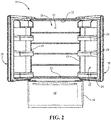
Figure 2 is an elevated front view of a French-Door Bottom Mount type refrigerator with the refrigerator compartment doors open; -
Figure 3 is a top isometric view of a shelving system for the refrigerator that includes first and second shelves; -
Figures 4-7 are isometric bottom views of the shelving system illustrating various positions of the second shelf relative to the first shelf; -
Figure 8 is a first partial isometric view of a roller and a track that are each subcomponents of the shelving system; -
Figure 9 is a second partial isometric view of the roller and the track; -
Figure 10 is a cross-sectional view taken along line 10-10 inFigure 7 illustrating an engagement between tab components of first and second shelves; -
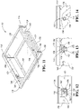
Figure 11 is an isometric top view of an alternative embodiment of the shelving system; -
Figure 12 is a side view of a first embodiment of a locking system that may be utilized to secure a lower shelf to an upper shelf of the alternative embodiment of the shelving system; -
Figure 13 is a side view of a second embodiment of the locking system that may be utilized to secure the lower shelf to the upper shelf of the alternative embodiment of the shelving system; and -
Figure 14 is a side view of a third embodiment of the locking system that may be utilized to secure the lower shelf to the upper shelf of the alternative embodiment of the shelving system. - Embodiments of the present disclosure are described herein. It is to be understood, however, that the disclosed embodiments are merely examples and other embodiments may take various and alternative forms. The figures are not necessarily to scale; some features could be exaggerated or minimized to show details of particular components. Therefore, specific structural and functional details disclosed herein are not to be interpreted as limiting, but merely as a representative basis for teaching one skilled in the art to variously employ the embodiments. As those of ordinary skill in the art will understand, various features illustrated and described with reference to any one of the figures may be combined with features illustrated in one or more other figures to produce embodiments that are not explicitly illustrated or described. The combinations of features illustrated provide representative embodiments for typical applications. Various combinations and modifications of the features consistent with the teachings of this disclosure, however, could be desired for particular applications or implementations.
- Referring to
Figures 1 and2 , generally arefrigerator 10 of the French-Door Bottom Mount type is illustrated. However, it should be understood that this disclosure could apply to any type of refrigerator, such as a side-by-side, two-door bottom mount, or a top-mount type. As shown inFigures 1 and2 , therefrigerator 10 may have a first internal storage chamber orfresh food compartment 12 configured to refrigerate and not freeze consumables within thefresh food compartment 12, and a second internal storage chamber or afreezer compartment 14 configured to freeze consumables within thefreezer compartment 14 during normal use. Therefrigerator 10 includes panels orwalls 13 that form a housing and define thefresh food compartment 12 and thefreezer compartment 14. Thewalls 13 may more specifically form an internal liner of therefrigerator 10. Thewalls 13 may include a rear or back wall, a top wall, a bottom wall, and two side walls. One or more shelves may be secured to thewalls 13 within thefood compartment 12. Therefrigerator 10 may have one ormore doors refrigerator 10 where consumables may be stored. As shown, the fresh food compartment doors are designated 16, and the freezer door is designated 18. It may also be shown that thefresh food compartment 12 may only have onedoor 16. Thedoors 16 may be rotatably secured to thewalls 13 by one or more hinges. - It is generally known that the
freezer compartment 14 is typically kept at a temperature below the freezing point of water, and thefresh food compartment 12 is typically kept at a temperature above the freezing point of water and generally below a temperature of from about 35° F. to about 50° F., more typically below about 38° F. - The
doors 16 may each include anexterior panel 20 and aninterior panel 22 that is disposed on an internal side of therespective exterior panel 20 of eachdoor 16. Theinterior panels 22 may be configured to face thefresh food 12 compartment when thedoors 16 are in closed positions (SeeFigure 1 ). Theinterior panel 22 may more specifically be a door liner. An insulating material, such as an insulating foam, may be disposed between theexterior panel 20 andinterior panel 22 of eachdoor 16 in order reduce the heat transfer from the ambient surroundings and increase the efficiency of the refrigerator. - The
refrigerator 10 may also have a water inlet that is fastened to and in fluid communication with a household water supply of potable water. Typically, the household water supply connects to a municipal water source or a well. The water inlet may be fluidly engaged with one or more of a water filter, a water reservoir, and a refrigerator water supply line. The refrigerator water supply line may include one or more nozzles and one or more valves. The refrigerator water supply line may supply water to one or more water outlets; typically one outlet for water is in the dispensing area and another to an ice tray. Therefrigerator 10 may also have a control board or controller that sends electrical signals to the one or more valves when prompted by a user that water is desired or if an ice making cycle is required. - Such a controller may be part of a larger control system and may be controlled by various other controllers throughout the
refrigerator 10, and one or more other controllers can collectively be referred to as a "controller" that controls various functions of therefrigerator 10 in response to inputs or signals to control functions of therefrigerator 10. The controller may include a microprocessor or central processing unit (CPU) in communication with various types of computer readable storage devices or media. Computer readable storage devices or media may include volatile and nonvolatile storage in read-only memory (ROM), random-access memory (RAM), and keep-alive memory (KAM), for example. KAM is a persistent or non-volatile memory that may be used to store various operating variables while the CPU is powered down. Computer-readable storage devices or media may be implemented using any of a number of known memory devices such as PROMs (programmable read-only memory), EPROMs (electrically PROM), EEPROMs (electrically erasable PROM), flash memory, or any other electric, magnetic, optical, or combination memory devices capable of storing data, some of which represent executable instructions, used by the controller in controlling therefrigerator 10. - The
doors 16 may also includestorage bins 24 that are able to hold food items or containers. Thestorage bins 24 may be secured to theinterior panels 22 of eachdoor 16. Alternatively, thestorage bins 24 may integrally formed within or defined by theinterior panels 22 of eachdoor 16. In yet another alternative, a portion of thestorage bins 24 may be secured to theinterior panels 22 of eachdoor 16, while another portion of thestorage bins 24 may be integrally formed within or defined by theinterior panels 22 of eachdoor 16. Thestorage bins 24 may include shelves (e.g., a lower surface upon, which a food item or container may rest upon) that extend from back and/or side surfaces of theinterior panels 22 of eachdoor 16. - Referring to
Figures 3-7 , ashelving system 26 for therefrigerator 10 is illustrated. Theshelving system 26 may be disposed within the internal chamber (i.e., the fresh food compartment 12) of therefrigerator 10. Asingle shelving system 26 or multiple shelving systems that are identical toshelving system 26 may be disposed within the internal chamber of the refrigerator. It should be noted that any shelves illustrated inFigure 2 may be removed or rearranged to create space for one or more of theshelving systems 26. Theshelving system 26 may includesupport arms 28 that engage one of thewalls 13 that define theinternal chamber 12 in order to secure the position of theshelving system 26 within theinternal chamber 12. More specifically, hooks 30 defined along the end of thesupport arms 28 may extend intonotches 32 defined by thewall 13 and may engage upwardly extendingprotrusions 34, bumps, walls, etc. within thenotches 32 to secure the position of theshelving system 26 within theinternal chamber 12. Thewall 13 may define a plurality of vertically alignednotches 32 havingprotrusions 34 disposed therein so that theshelving system 26 can be adjusted upward or downward betweennotches 32 in order to adjust a height of theshelving system 26 within theinternal chamber 12. - The
shelving system 26 includes an upper orfirst shelf 36 that is secured to or is integral to thesupport arms 28. Thefirst shelf 36 is secured to thewall 13 via thesupport arms 28. Thefirst shelf 36 has a top orupper surface 38 and a lower orbottom surface 40 that each extend between thesupport arms 28. Food or other items may be stored on thetop surface 38. Thetop surface 38 may be leveled to in order prevent items that are stored on thetop surface 38 from rolling or falling off thetop surface 38. It is noted that a panel that defines theupper surface 38 andbottom surface 40 is illustrated as being made from a transparent material, such as glass, inFigure 3 for illustrative purposes. It should also be noted that although the panel could be made from such a transparent material, this disclosure should not be construed as limited to such a configuration. - One or more roller guide tracks 42 may be disposed along the
bottom surface 40. More specifically, the roller guide tracks 42 may comprise first and second opposing roller guide tracks. The roller guide tracks 42 may be secured to thefirst shelf 36 and/or thesupport arms 28 along or adjacent to thebottom surface 40. Alternatively, the roller guide tracks 42 may be integral to and defined by thefirst shelf 36. The roller guide tracks 42 may be substantially parallel relative to each other and substantially parallel to thesupport arms 28. Substantially parallel may refer to any value that ranges between exactly parallel and 15° from exactly parallel. - One or more internal or inwardly protruding
tabs 44 extend inward from thefirst shelf 36 at a position that is below theupper surface 38 andbottom surface 40. More specifically, the inwardly protrudingtabs 44 may extend inward and toward each other from the roller guide tracks 42 at a position that is below theupper surface 38 andbottom surface 40. Each inwardly protrudingtab 44 may be substantially parallel to the other inwardly protrudingtabs 44. Substantially parallel may refer to any value that ranges between exactly parallel and 15° from exactly parallel. The inwardly protrudingtabs 44 may be substantially perpendicular to the roller guide tracks 42 and to thesupport arms 28. Substantially perpendicular may refer to any value that ranges between exactly perpendicular and 15° from exactly perpendicular. - The
shelving system 26 also includes one or more (or a plurality of) followers orrollers 46 and one or more (or a plurality of)hangers 48. At least one of therollers 46 is disposed within eachroller guide track 42. Stated in other terms, a first portion of therollers 46 may be disposed within a first of the roller guide tracks 42 and a second portion of therollers 46 may be disposed within a second of the roller guide tracks 42. Eachhanger 48 is rotatably secured to one of therollers 46 at a first end and is rotatably secured to a lower orsecond shelf 50 at a second end. Thesecond shelf 50 is disposed below thefirst shelf 36. Therollers 46 may define central orifices and thehangers 48 may have upper horizontal portions that are each disposed within the central orifice of oneroller 46 such that eachroller 46 may rotate freely about the upper horizontal portion of an associatedhanger 48. - The
second shelf 50 may definenotches 52 and lower horizontal portions of eachhanger 48 may be disposed in and may rotate freely within one of thenotches 52. Thehangers 48 include vertical portions that extend between the upper and lower horizontal portions. The upper horizontal portions and lower horizontal portions of eachhanger 48 may be substantially parallel to each other. Substantially parallel may refer to any value that ranges between exactly parallel and 15° from exactly parallel. The vertical portions of eachhanger 48 may be substantially perpendicular to the respective upper horizontal portion and lower horizontal portion of eachhanger 48. Thenotches 52 and lower horizontal portions of eachhanger 48 may be disposed along edges and at or proximate to each corner of thesecond shelf 50 to provide balance and stability to thesecond shelf 50 so that food or other items may be stored on atop surface 54 of thesecond shelf 50. The vertical portions of eachhanger 48 may be sized so that the four corners of thesecond shelf 50 are approximately located at the same vertical level in order prevent items that are stored on thetop surface 54 from rolling or falling off of thetop surface 54.Crossbars 56 may extend along abottom surface 58 of thesecond shelf 50 and may connect the lower horizontal portions of a pair ofhangers 48 to each other in order to provide further stability to thelower shelf 50. - One or more external or outwardly protruding
tabs 60 extend outward from thesecond shelf 50. More specifically, the outwardly protrudingtabs 60 may extend outward from opposing sides or side surfaces of thesecond shelf 50 and away from each other at positions that are below theupper surface 54. Each outwardly protrudingtab 60 may be substantially parallel to the other outwardlyprotruding tabs 60 and may be substantially parallel to the inwardly protrudingtabs 44. Substantially parallel may refer to any value that ranges between exactly parallel and 15° from exactly parallel. - One more stops 62 are disposed within each of the roller guide tracks 42 The
stops 62 are configured to limit linear movement of therollers 46 within the roller guide tracks 42. Thesecond shelf 50,hangers 48, androllers 46 are configured to slide forward from a lower-rearward position of the second shelf 50 (i.e., the position inFigure 4 ) via therollers 46 until the rollers engage thestops 62 at a lower-forward position. - The
second shelf 50 is then configured to rotate or pivot upward and forward about therollers 46 and via thehangers 48 from a lower or first position at a lower level (seeFigure 4 ) to a an upper-forward or second position at a upper level (seeFigure 6 ) upon engagement between therollers 46 and thestops 62. The first position may refer to any position at the lower lever or may more specifically refer to a position where therollers 46 first engage thestops 62 but rotation of theshelf 50 has yet to occur such thesecond shelf 50 is still at the lower level (i.e., the lower-forward position). Thesecond shelf 50 is suspended below thefirst shelf 36 via thehangers 48 while thesecond shelf 50 is at any position at the lower level. Thesecond shelf 50 is disposed at least partially forward of thefirst shelf 36 at the upper level when thesecond shelf 50 is in the upper-forward or second position (seeFigure 6 ).Figure 5 illustrates an intermediate position (i.e., a position of thesecond shelf 50 that is above the level lower and below the upper level) where thesecond shelf 50 is being rotated upward and forward about therollers 46 and via thehangers 48. - The
second shelf 50 is then configured to slide rearward at the upper level from the upper-forward or second position to an upper-rearward or third position where thesecond shelf 50 is completely below and nested within thefirst shelf 36 between the roller guide tracks 42 (seeFigure 7 ). The upper-forward or second position may also be referred to as an advanced position while the upper-rearward or third position may also be referred to as a nested or retracted position. Thesecond shelf 50 is configured to nest with thefirst shelf 36 and between the roller guide tracks 42 when in the upper-rearward or third position. More specifically, the outwardly protrudingtabs 60 are configured to engage with inwardly protrudingtabs 44 to nest thesecond shelf 50 to thefirst shelf 36 when thesecond shelf 50 is in the upper-rearward or third position. Even more specifically, the outwardly protrudingtabs 60 engageupper surfaces 64 of the inwardly protrudingtabs 44 to retain thelower shelf 50 in the upper-rearward or third position at the upper level. Nesting or nested objects (e.g., thesecond shelf 50 and thefirst shelf 36 as illustrated inFigure 7 ) may refer to when similar objects of graduated sizes are placed or stored one inside the other. - Referring to
Figures 8 and 9 , therollers 46 and portions of the roller guide tracks 42 are further illustrated. Although only oneroller 46 and oneroller guide track 42 are illustrated inFigures 8 and 9 , it should be understood that theroller 46 androller guide track 42 may be representative of all of theroller 46 and roller guide tracks 42 described herein. Furthermore, it should be understood that the roller and roller guide track configuration may include two roller guide tracks 42 withrollers 46 disposed therein that are mirror images to each other (seeFigures 3-7 ). - One or
more rails 66 may be disposed within the roller guide tracks 42. Therollers 46 may definegrooves 68. Therails 66 may be disposed within thegrooves 68 to guide therollers 46 linearly within the roller guide tracks 42 and to prevent therollers 46 from falling out of the roller guide tracks 42. Therails 66 may include an upper rail and a lower rail that are each disposed within thegrooves 68 of therollers 46. The stops 62 may be comprised of protrusions or bumps along therails 66 that limit or restrict the linear movement of therollers 46 along the roller guide tracks 42. For example, once therollers 46 come into contact with thestops 62. Therollers 46 are restricted from further movement within the roller guide tracks 42 and thesecond shelf 50 then begins to rotate about therollers 46 via thehangers 48. Thefirst shelf 36 includes one ormore backstops 70 that are configured to limit rearward movement of thehangers 48 and thesecond shelf 50 when thesecond shelf 50 is at the lower level and is suspended below thefirst shelf 36. Thebackstops 70 may be secured to or formed integrally with the roller guide tracks 42. - Referring to
Figure 10 , the engagement between the outwardly protrudingtabs 60 and the inwardly protrudingtabs 44 to nest thesecond shelf 50 to thefirst shelf 36 when thesecond shelf 50 is in the upper-rearward or third position (seeFigure 7 ) is further illustrated. The lower surfaces 72 of the outwardly protrudingtabs 60 may be ramped to facilitate engagement between the outwardly protrudingtabs 60 and the inwardly protrudingtabs 44. More specifically, while thesecond shelf 50 is being transitioned from the upper-forward or second position (seeFigure 6 ) to the upper-rearward or third position (seeFigure 7 ), the rampedlower surfaces 72 of the outwardly protrudingtabs 60 engage afront end 74 of the inwardly protrudingtabs 44 to force the outwardly protrudingtabs 60 above the inwardly protrudingtabs 44 such that outwardly protrudingtabs 60 rest on top of or engage theupper surfaces 64 of inwardly protrudingtabs 44 in order to ensure thesecond shelf 50 is property nested with thefirst shelf 36 once thesecond shelf 50 reaches the upper-rearward or third position. The front ends 74 of the inwardly protrudingtabs 44 may be rounded to further assist in forcing the outwardly protrudingtabs 60 above the inwardly protrudingtabs 44 and to prevent jamming between the inwardly protrudingtabs 44 and the outwardly protrudingtabs 60 during engagement between the inwardly protrudingtabs 44 and the outwardly protrudingtabs 60. - Referring to
Figure 11 , an alternative embodiment of theshelving system 126 is illustrated. The alternative embodiment of theshelving system 126 should be construed to include all of the subcomponents and functionality ofshelving system 26 unless otherwise described herein. Asingle shelving system 126 or multiple shelving systems that are identical toshelving system 126 may be disposed within the internal chamber of the refrigerator. It should be noted that any shelves illustrated inFigure 2 may be removed or rearranged to create space for one or more of theshelving systems 26 orshelving systems 126. Theshelving system 126 may includesupport arms 128 that engage one of thewalls 13 that define theinternal chamber 12 in order to secure the position of theshelving system 126 within theinternal chamber 12. More specifically, hooks 130 defined along the end of thesupport arms 128 may extend into notches defined by thewall 13 and may engage upwardly extending protrusions, bumps, walls, etc. within the notches to secure the position of theshelving system 126 within theinternal chamber 12, similar to how thehooks 30 secure theshelving system 26 to thewall 13 inFigure 3 . Thewall 13 may define a plurality of vertically aligned notches having protrusions disposed therein so that theshelving system 126 can be adjusted upward or downward between notches in order to adjust a height of theshelving system 126 within theinternal chamber 12. - The
shelving system 126 includes an upper orfirst shelf 136 that is secured to or is integral to thesupport arms 128. Thefirst shelf 136 is secured to thewall 13 via thesupport arms 128. Thefirst shelf 36 has a top orupper surface 138 and a lower or bottom surface that each extend between thesupport arms 128. Food or other items may be stored on thetop surface 138. Thetop surface 138 may be leveled to in order prevent items that are stored on thetop surface 138 from rolling or falling off thetop surface 138. It is noted that a panel that defines theupper surface 138 and bottom surface is illustrated as being made from a transparent material, such as glass, inFigure 11 for illustrative purposes. It should also be noted that although the panel could be made from such a transparent material, this disclosure should not be construed as limited to such a configuration. - The
shelving system 126 also includes one or more (or a plurality of) hangers 148. At. Eachhanger 148 is rotatably secured to thefirst shelf 136 at a first end and is rotatably secured to a lower or second shelf 150 at a second end. The second shelf 150 is disposed below thefirst shelf 136. Thefirst shelf 136, or more specificallyadaptors 151 that are secured to a bottom of thefirst shelf 136, may define orifices and thehangers 148 may have upper horizontal portions that are each disposed within the one of the orifices defined by theadaptors 151 such that thehangers 148 rotate freely relative to thefirst shelf 136 and theadaptors 151. - The second shelf 150 may define
notches 152 and lower horizontal portions of eachhanger 148 may be disposed in and may rotate freely within one of thenotches 152. Thehangers 148 include vertical portions that extend between the upper and lower horizontal portions. The upper horizontal portions and lower horizontal portions of eachhanger 148 may be substantially parallel to each other. Substantially parallel may refer to any value that ranges between exactly parallel and 15° from exactly parallel. The vertical portions of eachhanger 148 may be substantially perpendicular to the respective upper horizontal portion and lower horizontal portion of eachhanger 148. Thenotches 152 and lower horizontal portions of eachhanger 148 may be disposed along edges and at or proximate to each corner of the second shelf 150 to provide balance and stability to the second shelf 150 so that food or other items may be stored on atop surface 154 of the second shelf 150. The vertical portions of eachhanger 148 may be sized so that the four corners of the second shelf 150 are approximately located at the same vertical level in order prevent items that are stored on thetop surface 154 from rolling or falling off of thetop surface 154. Crossbars may extend along a bottom surface of the second shelf 150 and may connect the lower horizontal portions of a pair ofhangers 148 to each other in order to provide further stability to the second shelf 150. - The second shelf 150 is configured to rotate upward from a lower position (see
Figure 11 ) to an upper position where the second shelf 150 is nested with thefirst shelf 136. Such an example of the positioning of the second shelf 150 relative to thefirst shelf 136 when the second shelf 150 is nested with thefirst shelf 136 is demonstrated inFigure 7 with respect tosecond shelf 50 andfirst shelf 36. The difference betweenshelving system 126 andshelving system 26 is that a locking system is utilized to secure the second shelf 150 to thefirst shelf 136. The locking system includes one ormore locks 156 that are secured to the first shelf 136 (or more specifically to the adapters 151) and one or more protrusions orbosses 158 that extend from the second shelf 150. When the second shelf 150 is in the upper position, thelocks 156 are configured to retain thebosses 158, which in turn retains the second shelf 150 in upper positioned where the second shelf 150 is nested with thefirst shelf 136. - Referring to
Figure 12 , a first embodiment of one of thelocks 156 engaging one of thebosses 158 to secure the second shelf 150 in the upper position is illustrated. The remainder of the second shelf 150 (i.e., the portions of the second shelf 150 other than the boss 158) has been removed inFigure 12 for illustrative purposes. The first embodiment of thelocks 156 includes a pair of opposing J-shaped snaps or clips 160. Theclips 160 are configured to flex about biasingarms 162 when theboss 158 is engaging rampedsurfaces 164 of eachclip 160 during a transition of the lower shelf 150 to the upper position. Once theboss 158 passes beyond and above the rampedsurfaces 164, the pair ofclips 160 snaps back and theboss 158 is retained in a hand orpalm profile 166 that is formed by the pair of opposingclips 160. The ramped surfaces 164 facilitate inserting theboss 158 into and out of a retained position (i.e., where theboss 158 is being retained via the palm profile 166). - Referring to
Figure 13 , a second embodiment of one of thelocks 156 engaging one of thebosses 158 to secure the second shelf 150 in the upper position is illustrated. The remainder of the second shelf 150 (i.e., the portions of the second shelf 150 other than the boss 158) has been removed inFigure 13 for illustrative purposes. The second embodiment of thelocks 156 includes a pair of opposing inverted flexible clips or snaps 168. Thesnaps 168 are configured to flex about biasingarms 170 when theboss 158 is engaging rampedsurfaces 172 of eachsnap 168. Once theboss 158 passes beyond and above the rampedsurfaces 172, the pair ofsnaps 168 snap back and theboss 158 is retained withinrounded profiles 174 that are formed by thesnaps 168. The ramped surfaces 172 facilitate inserting theboss 158 into and out of a retained position (i.e., where theboss 158 is being retained via the rounded profiles 174). - Referring to
Figure 14 , a third embodiment of one of thelocks 156 engaging one of thebosses 158 to secure the second shelf 150 in the upper position is illustrated. The remainder of the second shelf 150 (i.e., the portions of the second shelf 150 other than the boss 158) has been removed inFigure 14 for illustrative purposes. The third embodiment of one of thelocks 156 is comprised of aguideway 176 that is define along an outer surface of theadaptor 151. Theguideway 176 includes afirst portion 178 that is angled upward and facilitates guiding theboss 158 when the second shelf 150 is being transitioned to the upper position. Theguideway 176 also includes a second portion 180 that forms a locking ramp that is angled downward relative to thefirst portion 178. The downward angle facilities retaining theboss 158 and maintaining the second shelf 150 in the upper position via gravity.
Claims (8)
- A refrigerator shelving system (26) comprising:a first shelf (36) having an upper surface (38), defining at least one track (42) below the upper surface (38), and having at least one inwardly protruding tab (44) disposed below the upper surface (38);at least one roller (46) disposed within the at least one track (42);at least one hanger (48) rotatably secured the at least one roller (46); anda second shelf (50) rotatably secured to the at least one hanger (48) and having at least one outwardly protruding tab (60), wherein (i) the second shelf (50) is configured to rotate upward and forward about the rollers (46) upon engagement between the at least one roller (46) and at least one stop (62) to transition from a first position to a second position, and (ii) the second shelf (50) is configured to slide rearward from the second position to a third position such that the at least one outwardly protruding tab (60) engages the at least one inwardly protruding tab (44) to nest the second shelf (50) to the first shelf (36).
- The refrigerator shelving system (26) of claim 1, wherein the second shelf (50) is suspended below the first shelf (36) via the at least one hanger (48) in the first position.
- The refrigerator shelving system (26) of claim 1, wherein the second shelf (50) is disposed at least partially forward of the first shelf (36) in the second position.
- The refrigerator shelving system (26) of claim 1, wherein (i) at least one rail (66) is disposed within the at least one track (42), (ii) the at least one roller (46) defines at least one groove (68), and (iii) the at least one rail (66) is disposed within the at least one groove (68) to guide the at least one roller (46) within the at least one track (42).
- The refrigerator shelving system (26) of claim 4, wherein the at least one stop (62) comprises at least one protrusion extending from the at least one rail (66).
- The refrigerator shelving system (26) of claim 1, wherein a lower surface (72) of the at least one outwardly protruding tab (60) is ramped to facilitate engagement between the at least one outwardly protruding tab (60) and the at least one inwardly protruding tab (44).
- The refrigerator shelving system (26) of claim 1, wherein the first shelf (36) includes at least one second stop (70) configured to limit rearward movement of the at least one hanger (48) when the second shelf (50) is in the first position.
- A refrigerator (10) comprising the shelving system (26) of any one of the preceding claims.
Applications Claiming Priority (1)
| Application Number | Priority Date | Filing Date | Title |
|---|---|---|---|
| US17/240,426 US11435133B1 (en) | 2021-04-26 | 2021-04-26 | Refrigerator and shelving system for a refrigerator |
Publications (2)
| Publication Number | Publication Date |
|---|---|
| EP4082395A1 true EP4082395A1 (en) | 2022-11-02 |
| EP4082395B1 EP4082395B1 (en) | 2024-06-05 |
Family
ID=81325526
Family Applications (1)
| Application Number | Title | Priority Date | Filing Date |
|---|---|---|---|
| EP22167043.3A Active EP4082395B1 (en) | 2021-04-26 | 2022-04-06 | Refrigerator and shelving system for a refrigerator |
Country Status (2)
| Country | Link |
|---|---|
| US (1) | US11435133B1 (en) |
| EP (1) | EP4082395B1 (en) |
Families Citing this family (5)
| Publication number | Priority date | Publication date | Assignee | Title |
|---|---|---|---|---|
| US11828530B2 (en) * | 2021-12-08 | 2023-11-28 | Electrolux Home Products, Inc. | Shelf assembly |
| US11740012B2 (en) * | 2022-01-21 | 2023-08-29 | Whirlpool Corporation | Refrigerator and shelving system for a refrigerator |
| US11910923B2 (en) * | 2022-03-02 | 2024-02-27 | Daniel L French | Shelving unit |
| US12523416B2 (en) * | 2022-05-20 | 2026-01-13 | Whirlpool Corporation | Refrigerator and shelving system for a refrigerator |
| US12435921B2 (en) * | 2023-11-07 | 2025-10-07 | Whirlpool Corporation | Refrigerator and shelving system for a refrigerator |
Citations (5)
| Publication number | Priority date | Publication date | Assignee | Title |
|---|---|---|---|---|
| KR20040039748A (en) * | 2002-11-04 | 2004-05-12 | 엘지전자 주식회사 | Structure of shelf for refrigerator |
| KR100582073B1 (en) * | 2004-12-15 | 2006-05-22 | 엘지전자 주식회사 | Auxiliary shelf assembly of refrigerator |
| US8152258B2 (en) * | 2006-11-20 | 2012-04-10 | Lg Electronics Inc. | Elevation adjustment apparatus for shelf in refrigerator |
| CN202562193U (en) * | 2012-03-12 | 2012-11-28 | 合肥美的荣事达电冰箱有限公司 | Commodity shelf and refrigerator with same |
| KR20170126575A (en) * | 2016-05-10 | 2017-11-20 | 엘지전자 주식회사 | A refrigerator |
Family Cites Families (35)
| Publication number | Priority date | Publication date | Assignee | Title |
|---|---|---|---|---|
| US1247367A (en) * | 1916-09-19 | 1917-11-20 | Theophilus T Burchell | Secret drawer. |
| US2064096A (en) * | 1935-06-20 | 1936-12-15 | John T Whalen | Shelf support |
| US2855262A (en) | 1954-01-19 | 1958-10-07 | Gen Motors Corp | Refrigerator storage tray |
| US3857623A (en) * | 1972-12-29 | 1974-12-31 | F Schneller | Swingable shelf assembly for cabinets |
| US4528825A (en) | 1984-08-20 | 1985-07-16 | Whirlpool Corporation | Fold-down multiple position shelf for refrigerator |
| US5273354A (en) | 1991-03-07 | 1993-12-28 | Donnelly Corporation | Molded refrigerator shelf and support bracket |
| US5302015A (en) * | 1992-03-12 | 1994-04-12 | Microcomputer Accessories, Inc. | Adjustable keyboard drawer |
| US5577823A (en) | 1995-07-21 | 1996-11-26 | Whirlpool Corporation | Lazy susan type pan/carriage assembly |
| DE19631374A1 (en) | 1996-08-02 | 1998-02-05 | Bosch Siemens Hausgeraete | Storage device |
| US6435634B1 (en) * | 2001-02-12 | 2002-08-20 | Steelcase Development Corporation | Document display shelf apparatus |
| US6997531B2 (en) * | 2002-03-15 | 2006-02-14 | Lg Electronics Inc. | Tray apparatus for refrigerator |
| US7316326B2 (en) * | 2003-03-18 | 2008-01-08 | Lg Electronics Inc. | Tray apparatus for refrigerator |
| US7270384B2 (en) * | 2003-11-05 | 2007-09-18 | General Electric Company | Support assembly for a refrigerator storage pan |
| US20060097613A1 (en) * | 2004-11-05 | 2006-05-11 | Lg Electronics Inc. | Refrigerator with height adjustable shelf |
| US7618103B2 (en) * | 2004-12-15 | 2009-11-17 | Lg Electronics Inc. | Supplementary shelf assembly for refrigerator |
| JP4480666B2 (en) | 2005-12-07 | 2010-06-16 | シャープ株式会社 | Refrigerator mounting shelf and refrigerator using the same |
| KR100650745B1 (en) | 2005-12-12 | 2006-11-27 | 주식회사 대우일렉트로닉스 | Two-stage shelf structure |
| DE102006014370A1 (en) * | 2006-03-27 | 2007-10-04 | BSH Bosch und Siemens Hausgeräte GmbH | Refrigerating equipment has housing enclosing internal space and storage device is adjusted in height by arms provided in internal space |
| US8226184B2 (en) | 2006-11-20 | 2012-07-24 | Lg Electronics Inc. | Height adjusting apparatus of shelf for refrigerator |
| US7950756B2 (en) * | 2007-08-28 | 2011-05-31 | Electrolux Home Products, Inc. | Drop-down shelf |
| AU2007229415A1 (en) | 2007-10-22 | 2009-05-07 | Ellipse Pty Ltd | Apparatus for Storing or Holding Items |
| TR200909658A2 (en) | 2009-12-22 | 2011-07-21 | Bsh Ev Aletleri̇ San. Ve Ti̇c. A.Ş. | A cooler with folding rack |
| DE102010039618A1 (en) * | 2010-08-20 | 2012-02-23 | BSH Bosch und Siemens Hausgeräte GmbH | Refrigeration unit with storage for refrigerated goods |
| CN202254617U (en) | 2011-09-19 | 2012-05-30 | 合肥荣事达三洋电器股份有限公司 | Wine rack for refrigerator |
| KR102043198B1 (en) * | 2013-03-05 | 2019-12-02 | 엘지전자 주식회사 | Refrigerator |
| US9222723B2 (en) * | 2013-07-09 | 2015-12-29 | Whirlpool Corporation | Foldable rack for a refrigerator |
| KR101622229B1 (en) | 2014-03-28 | 2016-05-18 | 엘지전자 주식회사 | Refrigerator |
| KR101618128B1 (en) | 2014-04-16 | 2016-05-04 | 엘지전자 주식회사 | Refrigerator |
| KR101647380B1 (en) * | 2014-11-24 | 2016-08-10 | 엘지전자 주식회사 | Refrigerator |
| CN204787579U (en) | 2015-07-02 | 2015-11-18 | 苏州三星电子有限公司 | Refrigerator and shelf thereof |
| CN104976856B (en) * | 2015-07-30 | 2018-09-04 | 合肥美的电冰箱有限公司 | Wine frame and refrigerator |
| US9644885B1 (en) * | 2015-12-17 | 2017-05-09 | Electrolux Home Products, Inc. | Spacer for an appliance |
| CN106524660B (en) * | 2016-12-16 | 2019-07-02 | 青岛海尔股份有限公司 | Refrigerator and its storage device |
| US11060789B2 (en) * | 2018-01-31 | 2021-07-13 | Ronald Beck | Under cabinet/shelf storage rack improvements |
| US10408530B1 (en) * | 2018-01-31 | 2019-09-10 | Ronald Beck | Under cabinet/shelf storage rack |
-
2021
- 2021-04-26 US US17/240,426 patent/US11435133B1/en active Active
-
2022
- 2022-04-06 EP EP22167043.3A patent/EP4082395B1/en active Active
Patent Citations (5)
| Publication number | Priority date | Publication date | Assignee | Title |
|---|---|---|---|---|
| KR20040039748A (en) * | 2002-11-04 | 2004-05-12 | 엘지전자 주식회사 | Structure of shelf for refrigerator |
| KR100582073B1 (en) * | 2004-12-15 | 2006-05-22 | 엘지전자 주식회사 | Auxiliary shelf assembly of refrigerator |
| US8152258B2 (en) * | 2006-11-20 | 2012-04-10 | Lg Electronics Inc. | Elevation adjustment apparatus for shelf in refrigerator |
| CN202562193U (en) * | 2012-03-12 | 2012-11-28 | 合肥美的荣事达电冰箱有限公司 | Commodity shelf and refrigerator with same |
| KR20170126575A (en) * | 2016-05-10 | 2017-11-20 | 엘지전자 주식회사 | A refrigerator |
Also Published As
| Publication number | Publication date |
|---|---|
| EP4082395B1 (en) | 2024-06-05 |
| US11435133B1 (en) | 2022-09-06 |
Similar Documents
| Publication | Publication Date | Title |
|---|---|---|
| EP4082395B1 (en) | Refrigerator and shelving system for a refrigerator | |
| US11460241B1 (en) | Refrigerator and shelving system for a refrigerator | |
| US12292231B2 (en) | Refrigerator and shelving system for a refrigerator | |
| EP4242564A1 (en) | Refrigerator and storage system for a refrigerator | |
| EP4343242A1 (en) | Refrigerator with a water storage tank | |
| US11573047B2 (en) | Refrigerator appliance | |
| US12146704B2 (en) | Refrigerator appliance and corresponding shelving system | |
| EP4361539A1 (en) | Refrigerator and mullion for a refrigerator | |
| US11480386B2 (en) | Refrigerator and shelving system for a refrigerator | |
| US20250389475A1 (en) | Refrigerator and storage system for a refrigerator | |
| US12435921B2 (en) | Refrigerator and shelving system for a refrigerator | |
| US12523416B2 (en) | Refrigerator and shelving system for a refrigerator | |
| US20250362074A1 (en) | Bin storage system for a refrigerator appliance | |
| US20230408183A1 (en) | Shelving system for a refrigerator | |
| US20260043604A1 (en) | Refrigerator and storage system for a refrigerator | |
| US20250012506A1 (en) | Refrigerator storage system | |
| US20260049756A1 (en) | Refrigerator and storage system for a refrigerator | |
| US12320578B2 (en) | Refrigerator and corresponding shelving system | |
| US11441835B1 (en) | Refrigerator appliance and containment system for contents of refrigerator appliance | |
| US20230228479A1 (en) | Refrigerator appliance | |
| US20250067504A1 (en) | Refrigerator and corresponding shelving system | |
| US12181208B2 (en) | Refrigerator appliance subcomponent mounting system | |
| BR102024013216A2 (en) | REFRIGERATOR STORAGE SYSTEM | |
| KR20070113414A (en) | Refrigerator | |
| KR19990019121A (en) | Height adjustment structure of the shelf for the refrigerator |
Legal Events
| Date | Code | Title | Description |
|---|---|---|---|
| PUAI | Public reference made under article 153(3) epc to a published international application that has entered the european phase |
Free format text: ORIGINAL CODE: 0009012 |
|
| STAA | Information on the status of an ep patent application or granted ep patent |
Free format text: STATUS: THE APPLICATION HAS BEEN PUBLISHED |
|
| AK | Designated contracting states |
Kind code of ref document: A1 Designated state(s): AL AT BE BG CH CY CZ DE DK EE ES FI FR GB GR HR HU IE IS IT LI LT LU LV MC MK MT NL NO PL PT RO RS SE SI SK SM TR |
|
| RAP3 | Party data changed (applicant data changed or rights of an application transferred) |
Owner name: WHIRLPOOL CORPORATION |
|
| STAA | Information on the status of an ep patent application or granted ep patent |
Free format text: STATUS: REQUEST FOR EXAMINATION WAS MADE |
|
| 17P | Request for examination filed |
Effective date: 20230421 |
|
| RBV | Designated contracting states (corrected) |
Designated state(s): AL AT BE BG CH CY CZ DE DK EE ES FI FR GB GR HR HU IE IS IT LI LT LU LV MC MK MT NL NO PL PT RO RS SE SI SK SM TR |
|
| GRAP | Despatch of communication of intention to grant a patent |
Free format text: ORIGINAL CODE: EPIDOSNIGR1 |
|
| STAA | Information on the status of an ep patent application or granted ep patent |
Free format text: STATUS: GRANT OF PATENT IS INTENDED |
|
| RIC1 | Information provided on ipc code assigned before grant |
Ipc: F25D 25/02 20060101ALI20231123BHEP Ipc: A47B 96/02 20060101AFI20231123BHEP |
|
| INTG | Intention to grant announced |
Effective date: 20231215 |
|
| P01 | Opt-out of the competence of the unified patent court (upc) registered |
Effective date: 20231220 |
|
| GRAS | Grant fee paid |
Free format text: ORIGINAL CODE: EPIDOSNIGR3 |
|
| GRAA | (expected) grant |
Free format text: ORIGINAL CODE: 0009210 |
|
| STAA | Information on the status of an ep patent application or granted ep patent |
Free format text: STATUS: THE PATENT HAS BEEN GRANTED |
|
| AK | Designated contracting states |
Kind code of ref document: B1 Designated state(s): AL AT BE BG CH CY CZ DE DK EE ES FI FR GB GR HR HU IE IS IT LI LT LU LV MC MK MT NL NO PL PT RO RS SE SI SK SM TR |
|
| REG | Reference to a national code |
Ref country code: CH Ref legal event code: EP |
|
| REG | Reference to a national code |
Ref country code: DE Ref legal event code: R096 Ref document number: 602022003740 Country of ref document: DE |
|
| REG | Reference to a national code |
Ref country code: IE Ref legal event code: FG4D |
|
| REG | Reference to a national code |
Ref country code: LT Ref legal event code: MG9D |
|
| PG25 | Lapsed in a contracting state [announced via postgrant information from national office to epo] |
Ref country code: BG Free format text: LAPSE BECAUSE OF FAILURE TO SUBMIT A TRANSLATION OF THE DESCRIPTION OR TO PAY THE FEE WITHIN THE PRESCRIBED TIME-LIMIT Effective date: 20240605 |
|
| REG | Reference to a national code |
Ref country code: NL Ref legal event code: MP Effective date: 20240605 |
|
| PG25 | Lapsed in a contracting state [announced via postgrant information from national office to epo] |
Ref country code: HR Free format text: LAPSE BECAUSE OF FAILURE TO SUBMIT A TRANSLATION OF THE DESCRIPTION OR TO PAY THE FEE WITHIN THE PRESCRIBED TIME-LIMIT Effective date: 20240605 Ref country code: FI Free format text: LAPSE BECAUSE OF FAILURE TO SUBMIT A TRANSLATION OF THE DESCRIPTION OR TO PAY THE FEE WITHIN THE PRESCRIBED TIME-LIMIT Effective date: 20240605 |
|
| PG25 | Lapsed in a contracting state [announced via postgrant information from national office to epo] |
Ref country code: GR Free format text: LAPSE BECAUSE OF FAILURE TO SUBMIT A TRANSLATION OF THE DESCRIPTION OR TO PAY THE FEE WITHIN THE PRESCRIBED TIME-LIMIT Effective date: 20240906 |
|
| PG25 | Lapsed in a contracting state [announced via postgrant information from national office to epo] |
Ref country code: ES Free format text: LAPSE BECAUSE OF FAILURE TO SUBMIT A TRANSLATION OF THE DESCRIPTION OR TO PAY THE FEE WITHIN THE PRESCRIBED TIME-LIMIT Effective date: 20240605 |
|
| PG25 | Lapsed in a contracting state [announced via postgrant information from national office to epo] |
Ref country code: LV Free format text: LAPSE BECAUSE OF FAILURE TO SUBMIT A TRANSLATION OF THE DESCRIPTION OR TO PAY THE FEE WITHIN THE PRESCRIBED TIME-LIMIT Effective date: 20240605 |
|
| PG25 | Lapsed in a contracting state [announced via postgrant information from national office to epo] |
Ref country code: NO Free format text: LAPSE BECAUSE OF FAILURE TO SUBMIT A TRANSLATION OF THE DESCRIPTION OR TO PAY THE FEE WITHIN THE PRESCRIBED TIME-LIMIT Effective date: 20240905 Ref country code: LV Free format text: LAPSE BECAUSE OF FAILURE TO SUBMIT A TRANSLATION OF THE DESCRIPTION OR TO PAY THE FEE WITHIN THE PRESCRIBED TIME-LIMIT Effective date: 20240605 Ref country code: HR Free format text: LAPSE BECAUSE OF FAILURE TO SUBMIT A TRANSLATION OF THE DESCRIPTION OR TO PAY THE FEE WITHIN THE PRESCRIBED TIME-LIMIT Effective date: 20240605 Ref country code: GR Free format text: LAPSE BECAUSE OF FAILURE TO SUBMIT A TRANSLATION OF THE DESCRIPTION OR TO PAY THE FEE WITHIN THE PRESCRIBED TIME-LIMIT Effective date: 20240906 Ref country code: FI Free format text: LAPSE BECAUSE OF FAILURE TO SUBMIT A TRANSLATION OF THE DESCRIPTION OR TO PAY THE FEE WITHIN THE PRESCRIBED TIME-LIMIT Effective date: 20240605 Ref country code: ES Free format text: LAPSE BECAUSE OF FAILURE TO SUBMIT A TRANSLATION OF THE DESCRIPTION OR TO PAY THE FEE WITHIN THE PRESCRIBED TIME-LIMIT Effective date: 20240605 Ref country code: BG Free format text: LAPSE BECAUSE OF FAILURE TO SUBMIT A TRANSLATION OF THE DESCRIPTION OR TO PAY THE FEE WITHIN THE PRESCRIBED TIME-LIMIT Effective date: 20240605 Ref country code: RS Free format text: LAPSE BECAUSE OF FAILURE TO SUBMIT A TRANSLATION OF THE DESCRIPTION OR TO PAY THE FEE WITHIN THE PRESCRIBED TIME-LIMIT Effective date: 20240905 |
|
| PG25 | Lapsed in a contracting state [announced via postgrant information from national office to epo] |
Ref country code: NL Free format text: LAPSE BECAUSE OF FAILURE TO SUBMIT A TRANSLATION OF THE DESCRIPTION OR TO PAY THE FEE WITHIN THE PRESCRIBED TIME-LIMIT Effective date: 20240605 |
|
| REG | Reference to a national code |
Ref country code: AT Ref legal event code: MK05 Ref document number: 1691775 Country of ref document: AT Kind code of ref document: T Effective date: 20240605 |
|
| PG25 | Lapsed in a contracting state [announced via postgrant information from national office to epo] |
Ref country code: NL Free format text: LAPSE BECAUSE OF FAILURE TO SUBMIT A TRANSLATION OF THE DESCRIPTION OR TO PAY THE FEE WITHIN THE PRESCRIBED TIME-LIMIT Effective date: 20240605 |
|
| PG25 | Lapsed in a contracting state [announced via postgrant information from national office to epo] |
Ref country code: PT Free format text: LAPSE BECAUSE OF FAILURE TO SUBMIT A TRANSLATION OF THE DESCRIPTION OR TO PAY THE FEE WITHIN THE PRESCRIBED TIME-LIMIT Effective date: 20241007 |
|
| PG25 | Lapsed in a contracting state [announced via postgrant information from national office to epo] |
Ref country code: PT Free format text: LAPSE BECAUSE OF FAILURE TO SUBMIT A TRANSLATION OF THE DESCRIPTION OR TO PAY THE FEE WITHIN THE PRESCRIBED TIME-LIMIT Effective date: 20241007 |
|
| PG25 | Lapsed in a contracting state [announced via postgrant information from national office to epo] |
Ref country code: PL Free format text: LAPSE BECAUSE OF FAILURE TO SUBMIT A TRANSLATION OF THE DESCRIPTION OR TO PAY THE FEE WITHIN THE PRESCRIBED TIME-LIMIT Effective date: 20240605 |
|
| PG25 | Lapsed in a contracting state [announced via postgrant information from national office to epo] |
Ref country code: EE Free format text: LAPSE BECAUSE OF FAILURE TO SUBMIT A TRANSLATION OF THE DESCRIPTION OR TO PAY THE FEE WITHIN THE PRESCRIBED TIME-LIMIT Effective date: 20240605 |
|
| PG25 | Lapsed in a contracting state [announced via postgrant information from national office to epo] |
Ref country code: AT Free format text: LAPSE BECAUSE OF FAILURE TO SUBMIT A TRANSLATION OF THE DESCRIPTION OR TO PAY THE FEE WITHIN THE PRESCRIBED TIME-LIMIT Effective date: 20240605 Ref country code: IS Free format text: LAPSE BECAUSE OF FAILURE TO SUBMIT A TRANSLATION OF THE DESCRIPTION OR TO PAY THE FEE WITHIN THE PRESCRIBED TIME-LIMIT Effective date: 20241005 |
|
| PG25 | Lapsed in a contracting state [announced via postgrant information from national office to epo] |
Ref country code: CZ Free format text: LAPSE BECAUSE OF FAILURE TO SUBMIT A TRANSLATION OF THE DESCRIPTION OR TO PAY THE FEE WITHIN THE PRESCRIBED TIME-LIMIT Effective date: 20240605 |
|
| PG25 | Lapsed in a contracting state [announced via postgrant information from national office to epo] |
Ref country code: SK Free format text: LAPSE BECAUSE OF FAILURE TO SUBMIT A TRANSLATION OF THE DESCRIPTION OR TO PAY THE FEE WITHIN THE PRESCRIBED TIME-LIMIT Effective date: 20240605 Ref country code: RO Free format text: LAPSE BECAUSE OF FAILURE TO SUBMIT A TRANSLATION OF THE DESCRIPTION OR TO PAY THE FEE WITHIN THE PRESCRIBED TIME-LIMIT Effective date: 20240605 |
|
| PG25 | Lapsed in a contracting state [announced via postgrant information from national office to epo] |
Ref country code: SM Free format text: LAPSE BECAUSE OF FAILURE TO SUBMIT A TRANSLATION OF THE DESCRIPTION OR TO PAY THE FEE WITHIN THE PRESCRIBED TIME-LIMIT Effective date: 20240605 |
|
| PG25 | Lapsed in a contracting state [announced via postgrant information from national office to epo] |
Ref country code: SM Free format text: LAPSE BECAUSE OF FAILURE TO SUBMIT A TRANSLATION OF THE DESCRIPTION OR TO PAY THE FEE WITHIN THE PRESCRIBED TIME-LIMIT Effective date: 20240605 Ref country code: SK Free format text: LAPSE BECAUSE OF FAILURE TO SUBMIT A TRANSLATION OF THE DESCRIPTION OR TO PAY THE FEE WITHIN THE PRESCRIBED TIME-LIMIT Effective date: 20240605 Ref country code: RO Free format text: LAPSE BECAUSE OF FAILURE TO SUBMIT A TRANSLATION OF THE DESCRIPTION OR TO PAY THE FEE WITHIN THE PRESCRIBED TIME-LIMIT Effective date: 20240605 Ref country code: PL Free format text: LAPSE BECAUSE OF FAILURE TO SUBMIT A TRANSLATION OF THE DESCRIPTION OR TO PAY THE FEE WITHIN THE PRESCRIBED TIME-LIMIT Effective date: 20240605 Ref country code: IS Free format text: LAPSE BECAUSE OF FAILURE TO SUBMIT A TRANSLATION OF THE DESCRIPTION OR TO PAY THE FEE WITHIN THE PRESCRIBED TIME-LIMIT Effective date: 20241005 Ref country code: EE Free format text: LAPSE BECAUSE OF FAILURE TO SUBMIT A TRANSLATION OF THE DESCRIPTION OR TO PAY THE FEE WITHIN THE PRESCRIBED TIME-LIMIT Effective date: 20240605 Ref country code: CZ Free format text: LAPSE BECAUSE OF FAILURE TO SUBMIT A TRANSLATION OF THE DESCRIPTION OR TO PAY THE FEE WITHIN THE PRESCRIBED TIME-LIMIT Effective date: 20240605 Ref country code: AT Free format text: LAPSE BECAUSE OF FAILURE TO SUBMIT A TRANSLATION OF THE DESCRIPTION OR TO PAY THE FEE WITHIN THE PRESCRIBED TIME-LIMIT Effective date: 20240605 |
|
| PG25 | Lapsed in a contracting state [announced via postgrant information from national office to epo] |
Ref country code: IT Free format text: LAPSE BECAUSE OF FAILURE TO SUBMIT A TRANSLATION OF THE DESCRIPTION OR TO PAY THE FEE WITHIN THE PRESCRIBED TIME-LIMIT Effective date: 20240605 |
|
| REG | Reference to a national code |
Ref country code: DE Ref legal event code: R097 Ref document number: 602022003740 Country of ref document: DE |
|
| PLBE | No opposition filed within time limit |
Free format text: ORIGINAL CODE: 0009261 |
|
| STAA | Information on the status of an ep patent application or granted ep patent |
Free format text: STATUS: NO OPPOSITION FILED WITHIN TIME LIMIT |
|
| PG25 | Lapsed in a contracting state [announced via postgrant information from national office to epo] |
Ref country code: DK Free format text: LAPSE BECAUSE OF FAILURE TO SUBMIT A TRANSLATION OF THE DESCRIPTION OR TO PAY THE FEE WITHIN THE PRESCRIBED TIME-LIMIT Effective date: 20240605 |
|
| 26N | No opposition filed |
Effective date: 20250306 |
|
| PGFP | Annual fee paid to national office [announced via postgrant information from national office to epo] |
Ref country code: DE Payment date: 20250428 Year of fee payment: 4 |
|
| PG25 | Lapsed in a contracting state [announced via postgrant information from national office to epo] |
Ref country code: SE Free format text: LAPSE BECAUSE OF FAILURE TO SUBMIT A TRANSLATION OF THE DESCRIPTION OR TO PAY THE FEE WITHIN THE PRESCRIBED TIME-LIMIT Effective date: 20240605 |
|
| REG | Reference to a national code |
Ref country code: CH Ref legal event code: H13 Free format text: ST27 STATUS EVENT CODE: U-0-0-H10-H13 (AS PROVIDED BY THE NATIONAL OFFICE) Effective date: 20251125 |
|
| PG25 | Lapsed in a contracting state [announced via postgrant information from national office to epo] |
Ref country code: LU Free format text: LAPSE BECAUSE OF NON-PAYMENT OF DUE FEES Effective date: 20250406 |
|
| PG25 | Lapsed in a contracting state [announced via postgrant information from national office to epo] |
Ref country code: MC Free format text: LAPSE BECAUSE OF FAILURE TO SUBMIT A TRANSLATION OF THE DESCRIPTION OR TO PAY THE FEE WITHIN THE PRESCRIBED TIME-LIMIT Effective date: 20240605 |
|
| REG | Reference to a national code |
Ref country code: BE Ref legal event code: MM Effective date: 20250430 |
|
| PG25 | Lapsed in a contracting state [announced via postgrant information from national office to epo] |
Ref country code: FR Free format text: LAPSE BECAUSE OF NON-PAYMENT OF DUE FEES Effective date: 20250430 |
|
| PG25 | Lapsed in a contracting state [announced via postgrant information from national office to epo] |
Ref country code: BE Free format text: LAPSE BECAUSE OF NON-PAYMENT OF DUE FEES Effective date: 20250430 |
|
| PG25 | Lapsed in a contracting state [announced via postgrant information from national office to epo] |
Ref country code: CH Free format text: LAPSE BECAUSE OF NON-PAYMENT OF DUE FEES Effective date: 20250430 |
|
| PG25 | Lapsed in a contracting state [announced via postgrant information from national office to epo] |
Ref country code: IE Free format text: LAPSE BECAUSE OF NON-PAYMENT OF DUE FEES Effective date: 20250406 |