EP4082323A1 - Siebeinrichtung mit zumindest einer absaugdüse - Google Patents
Siebeinrichtung mit zumindest einer absaugdüse Download PDFInfo
- Publication number
- EP4082323A1 EP4082323A1 EP21214229.3A EP21214229A EP4082323A1 EP 4082323 A1 EP4082323 A1 EP 4082323A1 EP 21214229 A EP21214229 A EP 21214229A EP 4082323 A1 EP4082323 A1 EP 4082323A1
- Authority
- EP
- European Patent Office
- Prior art keywords
- suction
- connection
- suction nozzle
- hollow body
- screen
- Prior art date
- Legal status (The legal status is an assumption and is not a legal conclusion. Google has not performed a legal analysis and makes no representation as to the accuracy of the status listed.)
- Pending
Links
Images



Classifications
-
- A—HUMAN NECESSITIES
- A01—AGRICULTURE; FORESTRY; ANIMAL HUSBANDRY; HUNTING; TRAPPING; FISHING
- A01D—HARVESTING; MOWING
- A01D41/00—Combines, i.e. harvesters or mowers combined with threshing devices
- A01D41/12—Details of combines
- A01D41/1252—Anti-dust devices
-
- A—HUMAN NECESSITIES
- A01—AGRICULTURE; FORESTRY; ANIMAL HUSBANDRY; HUNTING; TRAPPING; FISHING
- A01D—HARVESTING; MOWING
- A01D41/00—Combines, i.e. harvesters or mowers combined with threshing devices
- A01D41/02—Self-propelled combines
-
- F—MECHANICAL ENGINEERING; LIGHTING; HEATING; WEAPONS; BLASTING
- F01—MACHINES OR ENGINES IN GENERAL; ENGINE PLANTS IN GENERAL; STEAM ENGINES
- F01P—COOLING OF MACHINES OR ENGINES IN GENERAL; COOLING OF INTERNAL-COMBUSTION ENGINES
- F01P11/00—Component parts, details, or accessories not provided for in, or of interest apart from, groups F01P1/00 - F01P9/00
- F01P11/06—Cleaning; Combating corrosion
-
- F—MECHANICAL ENGINEERING; LIGHTING; HEATING; WEAPONS; BLASTING
- F01—MACHINES OR ENGINES IN GENERAL; ENGINE PLANTS IN GENERAL; STEAM ENGINES
- F01P—COOLING OF MACHINES OR ENGINES IN GENERAL; COOLING OF INTERNAL-COMBUSTION ENGINES
- F01P11/00—Component parts, details, or accessories not provided for in, or of interest apart from, groups F01P1/00 - F01P9/00
- F01P11/12—Filtering, cooling, or silencing cooling-air
-
- B—PERFORMING OPERATIONS; TRANSPORTING
- B01—PHYSICAL OR CHEMICAL PROCESSES OR APPARATUS IN GENERAL
- B01D—SEPARATION
- B01D46/00—Filters or filtering processes specially modified for separating dispersed particles from gases or vapours
- B01D46/24—Particle separators, e.g. dust precipitators, using rigid hollow filter bodies
- B01D46/26—Particle separators, e.g. dust precipitators, using rigid hollow filter bodies rotatable
-
- B—PERFORMING OPERATIONS; TRANSPORTING
- B01—PHYSICAL OR CHEMICAL PROCESSES OR APPARATUS IN GENERAL
- B01D—SEPARATION
- B01D46/00—Filters or filtering processes specially modified for separating dispersed particles from gases or vapours
- B01D46/66—Regeneration of the filtering material or filter elements inside the filter
- B01D46/68—Regeneration of the filtering material or filter elements inside the filter by means acting on the cake side involving movement with regard to the filter elements
- B01D46/682—Regeneration of the filtering material or filter elements inside the filter by means acting on the cake side involving movement with regard to the filter elements by nozzles
-
- F—MECHANICAL ENGINEERING; LIGHTING; HEATING; WEAPONS; BLASTING
- F01—MACHINES OR ENGINES IN GENERAL; ENGINE PLANTS IN GENERAL; STEAM ENGINES
- F01P—COOLING OF MACHINES OR ENGINES IN GENERAL; COOLING OF INTERNAL-COMBUSTION ENGINES
- F01P3/00—Liquid cooling
- F01P3/20—Cooling circuits not specific to a single part of engine or machine
Definitions
- the present invention relates to a screening device with at least one suction nozzle according to the preamble of claim 1.
- the present invention also relates to a self-propelled harvesting machine according to the preamble of claim 15.
- a sieve device with at least one suction nozzle is used on the cooling devices of self-propelled harvesting machines in order to prevent foreign bodies sucked in by a fan of the cooling device, such as chaff, husk leaves and the like, as well as other dirt particles, being fed with the cooling air flow to a drive unit of the self-propelled harvesting machine that is to be cooled. which creates the risk of fire.
- the cooling air flow from the blower flows through a screen of the screening device, foreign bodies and dirt particles contained therein being deposited on the surface of the screen. These foreign bodies and dirt particles are sucked off the surface of the screen by the suction nozzle, which has a suction opening facing the screen and is connected to a vacuum source.
- connection for the vacuum source is usually located at an outer end of the suction nozzle, so that the suction capacity of the vacuum source decreases continuously in the longitudinal direction of the suction nozzle.
- the distal end of the suction nozzle must traverse a larger surface area and remove much more debris than the proximal end of the suction nozzle, which is closer to a central hub and connection of the suction nozzle to the vacuum source.
- power at the distal end of the suction nozzle is reduced due to the relatively higher velocity and hence shorter residence time of the distal end of the suction nozzle compared to the relatively lower surface velocity near the center of the suction nozzle.
- a screening device with a suction nozzle of the type mentioned above is from EP 3 149 305 B1 known.
- To equalize the suction power is according to the EP 3 149 305 B1 intended to carry out the suction nozzle with a plurality of slit openings through a common air duct in the suction nozzle having a hollow body are fluidly connected to each other.
- the slit openings are distributed at different distances from one another in the longitudinal direction of the suction nozzle.
- the object of the invention is to further develop a sieve device with at least one suction nozzle of the type mentioned at the outset, which is characterized by improved suction power in the region of the suction nozzle distal to the connection.
- a screening device with at least one suction nozzle which has an elongated hollow body with at least one suction opening, which extends in sections in the longitudinal direction and transverse direction of the hollow body and through at least one air duct inside the hollow body with a connection arranged on the hollow body is connected to a vacuum source, wherein the at least one suction opening is arranged facing a screen of the screening device.
- the at least one air duct has a cross-section that increases in the vertical direction, starting from an outer end of the suction nozzle in the direction of the connection, with an inner contour of the at least one air duct facing the at least one suction opening having a contour that essentially corresponds to an airfoil profile.
- the flow speed of the suction air stream increases with increasing distance from the connection, which reaches its maximum value at the end of the suction opening facing the outer end of the suction nozzle having.
- This increases the suction speed in the distal area of the suction nozzle, which improves the detachment of adhesions on the screen of the screening device.
- the improved sieve device increases the functional reliability of the suction.
- a vacuum source can be used necessarily funded flow rate are at least kept constant or even reduced.
- the inner contour of the at least one air duct can preferably initially have a first area with a sectionally convex course, which merges into a second area with a sectionally concave course and towards the outer end of the hollow body into a third area with a convex course transforms. Due to this course of the inner contour, the flow rate of the suction air stream increases from the area of the at least one suction opening that is furthest away from the connection in the direction of the connection.
- the respective extension of at least the first and second areas in the longitudinal direction of the suction nozzle allows the flow behavior in the at least one air duct to be flexibly adjusted.
- the second area can extend in the longitudinal direction essentially over a third to half of the longitudinal extent of the at least one air duct.
- a profile section can extend in sections, starting from the connection, in the longitudinal direction of the hollow body. Such a profile section can be used to have an additional influence on the flow behavior inside the hollow body.
- an upper side of the profile section facing the inner contour can have a course that essentially corresponds to the first region of the air duct.
- the suction nozzle can have, in particular precisely, two suction openings which are arranged one behind the other in the longitudinal direction and are connected to the connection by separate air ducts. Due to the separate air ducts designed according to the invention, in the case of two suction openings a smaller quantity of particles adhering to the sieve must be removed by the respective suction air flow, as a result of which the conveying effect increases.
- the two suction openings can have an extension that is essentially half the longitudinal extension of a corresponds to the effective total suction length of the suction nozzle.
- the total suction length essentially corresponds to the radial extent of the sieve swept over by the suction nozzle, within which particles are suctioned off the surface of the sieve.
- the two suction openings can preferably be arranged laterally offset from one another, viewed in the longitudinal direction.
- a sectional overlapping of the two suction openings can be provided. Due to the overlapping in sections, better suction can be achieved in a transition region between the suction openings, which is formed in the longitudinal direction of the suction nozzle.
- two suction nozzles can be arranged opposite one another and have a common connection.
- the common connection can be arranged coaxially to an imaginary axis running perpendicularly to the center point of the screen.
- connection can be arranged substantially centrally on the hollow body of the suction nozzle, and starting from the centrally arranged connection, mirror-inverted air ducts can extend on both sides, which are connected to the connection by a continuous suction opening.
- Two air ducts can also be provided on each side of the suction nozzle, which extend at least one behind the other and optionally additionally offset to one another in the longitudinal direction of the suction nozzle.
- connection can be arranged essentially in the middle of the hollow body of the suction nozzle, and starting from the connection arranged in the middle, mirror-inverted air channels can extend on both sides, which connect several suction openings to the connection.
- connection can be arranged eccentrically and extend essentially perpendicularly to a side wall of the hollow body.
- the screen can preferably be driven in rotation and the at least one suction nozzle can be arranged in a stationary manner relative to the screen.
- This arrangement enables an arrangement of, for example, two diametrically arranged suction nozzles with a common connection in the middle of the screen and the embodiment of the arrangement of the connection in the middle of the hollow body of the suction nozzle.
- the screen can be fixed and the suction nozzle can be movable relative to the screen.
- the task set at the outset is achieved by a self-propelled harvesting machine according to claim 15 .
- a self-propelled harvesting machine with a screening device comprising a screen is proposed, with the screen being assigned a suction nozzle whose at least one essentially slot-shaped suction opening is positioned facing the screen, the screening device being designed according to one of the preceding claims.
- the harvesting machine 1 shows an example and a schematic of a self-propelled harvesting machine 1 embodied as a forage harvester.
- the harvesting machine 1 can also be embodied as a self-propelled combine harvester.
- the harvesting machine 1 comprises a drive unit 2 designed as an internal combustion engine, to which a cooling device 3 is assigned.
- the cooling device 3 comprises a suction fan 4 which draws in a flow of cooling air through a screening device 5 .
- the screening device 5 has a screen 6 .
- the screen 6 is driven in rotation about an axis 7 in the illustrated embodiment.
- the screening device 5 comprises at least one suction nozzle 8.
- the at least one suction nozzle 8 is connected to a vacuum source 11 by means of a supply line 10 via a connection 9 arranged on the end thereof.
- the vacuum source 11 is designed, for example, as an after-accelerator 12 of the self-propelled harvesting machine 1 designed as a forage harvester, which works like a suction fan.
- the negative pressure source 11 can preferably be designed as a separate suction fan 15, as in 2 shown as an example, which can be regulated independently of the operating state of the harvesting machine 1 by a control unit, for example a drive control unit.
- a substantially funnel-shaped sieve 6 is stationarily arranged on a frame 13 in the engine compartment of the harvesting machine 1 .
- the at least one suction nozzle 8 is arranged to rotate about the axis 7 .
- the at least one suction nozzle 8 has an elongated hollow body 14 with at least one suction opening 16 which extends in sections in the longitudinal direction x, ie in the radial direction in relation to the axis 7 , and in the transverse direction y of the hollow body 14 .
- the at least one suction opening 16 is connected through at least one air duct 17 in the interior of the hollow body 14 to the connection 9 arranged on the hollow body 14 for connection to the vacuum source 11 .
- the at least one suction opening 16 is arranged facing the screen 6 of the screening device 5 . Seen in the transverse direction y, the suction nozzle 8 can have a substantially constant width B over its entire length.
- the representation in 3 shows a first embodiment of the suction nozzle 8 of the screening device 5 in longitudinal section.
- the air duct 17 inside the hollow body 14 extends from the connection 9, on which the supply line 10 is arranged, to the outer end 18 of the suction nozzle 8.
- the hollow body 14 points in the longitudinal direction x of the hollow body 14 up to the connection 9 has a cross-sectional course that increases in the vertical direction z of the hollow body 14 .
- An inner contour 19 of the at least one air duct 17 facing the at least one suction opening 16 has a contour that essentially corresponds to an airfoil profile.
- the inner contour 19 is the area in the interior of the hollow body 14 that runs parallel to the at least one suction opening 16 and through which the cross-sectional profile in the vertical direction z can be changed.
- the inner contour 19, which corresponds to an airfoil profile, leads to a variation of the cross-section through which the suction air flow flows inside the suction nozzle 8, so that with a predetermined suction air volume flow in a section of the at least one suction opening 16 that is further away from the connection 9, an increase in the flow speed of the suction air flow is brought about. In this way, an increase in the extraction speed can be achieved without increasing the extraction air volume flow at the same time.
- the functional reliability of the cooling device 3 is increased by the improved suction of the screen 6.
- the inner contour 19 of the at least one air duct 17 of the suction nozzle 8 initially has a first region 20 with a sectionally convex course, which merges into a second region 21 with a sectionally concave course and to the outer end 18 of the hollow body 14 transitions out into a third region 22 with a convex shape.
- the suction nozzle 8 can have a contour profile that deviates from the inner contour 19 .
- Arrows 23 indicate the suction direction of a suction air flow, in which at least one suction opening 16 of the suction nozzle 8 facing the - only indicated - sieve 6 of the sieve device 5 draws in or sucks off the suction air flow together with particles that are deposited on the surface of the sieve.
- the extent of the suction opening 16 in the longitudinal direction describes the effective total suction length of the suction nozzle 8, via which the screen surface of the screen 6 is suctioned off.
- the vertical distance between the suction opening 16 and the inner contour 19 is reduced by a profile section 24 extending in sections in the longitudinal direction x.
- the profile section 24 extends across the width of the suction nozzle 8 as viewed in the transverse direction y.
- the profile section 24 thus forms a closed surface which extends in the transverse direction of the hollow body 14 .
- the profile section 24 has a contour of its upper side 25 facing the inner contour 19 that corresponds to the course of the first region 20 .
- the contour of the top 25 curves outwards, i.e. it extends in the direction of the first area 20 of the inner contour 19. Starting from the area of the connection 9, the course of the contour of the top 25 initially rises, only to fall after a turning point.
- a front section 26 facing the outer end 18 of the suction nozzle 8 is designed as a nose with a small radius of curvature in order to minimize or avoid turbulence on the front section 26 .
- the profile section 24 causes a cross-section reduction in the first region 20 over its partial extension in the longitudinal direction x, as a result of which the flow rate of the suction air stream initially increases.
- the increase in the distance between the suction opening 16 and the inner contour 19 results in a sudden widening of the cross section. This reduces the flow rate of the suction air flow.
- the cross section decreases continuously, which results in an increase in the flow rate of the suction air stream.
- the second area 21 extends in the longitudinal direction x essentially over a third to half the length of the air duct 17.
- the flow velocity increases with increasing distance from the first area 20 of the suction air flow, whereby the suction of adhering particles deposited on the surface of the screen 6, in particular in the distal suction region of the suction nozzle 8, is improved.
- the third area 22 forms the outer end 18 of the suction nozzle 8.
- the third area 22 is the shortest and also has the smallest cross-section.
- the concave profile of the third section 22 forms a frontal delimitation of the hollow body 14 .
- the suction air flow is primarily deflected here.
- FIG 4 is a further embodiment of the suction nozzle 8 for the screening device 5 according to FIG 2 shown.
- the 4 Suction nozzle 8 shown is in a opposite to the representation according to 3 Arrangement rotated by 180° to the vertical direction z.
- the basic structure is identical to that in 3 illustrated suction nozzle 8, so that the reference numerals used there are retained for identical components and parts.
- a differently designed profile section 27 is provided.
- the profile section 27 extends in the longitudinal direction x over almost the entire length of the suction opening 16.
- the profile section 27 also has a course of the contour of its upper side 28 facing the inner contour 19 which initially corresponds to the first area 20 and which in the first area 20 is divided into a essentially parallel to the suction opening 16 course.
- the profile section 27 extends almost to the end of the second region 21 of the inner contour 19, so that a gap-shaped opening 29 extending in the transverse direction y remains. Due to the fact that the upper side 28 of the profile section 27 extends essentially parallel to the suction opening 16 , the cross-section through which flow occurs between the inner contour 19 and the upper side 28 in the longitudinal direction x is continuously reduced. Thus, the suction air flow transition from the second area 21 to the third area 22 and in the third area 22 has the highest flow speed.
- a front section 30 of the profile section 27 facing the outer end 18 of the suction nozzle 8 is also designed as a nose with a small radius of curvature.
- the suction air flow sucked in through the suction opening 16 is deflected around the end section 30 of the profile section 27 .
- the underside 31 of the profile section 27 faces the suction opening 16 .
- the contour of the underside 31 of the profile section 27 has, starting from the connection 9, a lengthwise direction x im Substantially ramped up course.
- a distance 32 formed between the suction opening 16 and the underside 31 of the profile section 27 increases in the longitudinal direction x.
- the design of the underside 31 of the profile section 27 ensures that an adequate suction effect is also achieved in the region of the suction nozzle 8 facing the connection 9 .
- the distance 32 is greatest at the end of the underside 31 in the end section 30 .
- the effect otherwise achieved by the configuration of the profile section 27 essentially corresponds to that according to the embodiment according to FIG 3 .
- the suction takes place over the entire length of the suction opening 16 with an undivided flow of suction air.
- the flow rate of the suction air stream increases in the longitudinal direction x between the upper side 28 of the profile section 27 and the inner contour 19 due to the contour corresponding to the airfoil profile, while on the underside 30 of the profile section 27, starting from the area of the profile section closest to the connection 9 27 in the longitudinal direction x a decrease in the flow rate of the suction air flow is caused by the ramp-shaped course of the underside 30.
- Figures 5a and 5b show schematically a further embodiment of a suction nozzle 8 for a screening device according to FIG 2 in longitudinal section.
- the sectional planes are offset from one another in the transverse direction y. So shows Figure 5a a region further forward in the transverse direction y and Figure 5b an area of the suction nozzle 8 that is offset further to the rear in the transverse direction y Figures 2 to 4 illustrated embodiments of the suction nozzle 8.
- the suction nozzle 8 in Figures 5a and 5b has two suction openings 33, 34 which are arranged one behind the other as seen in the longitudinal direction x.
- the two suction openings 33, 34 each extend in sections in the longitudinal direction x of the suction nozzle 8.
- the two suction openings 33, 34 can, as in FIG 6 shown schematically, also be offset from one another in the transverse direction y.
- the respective suction opening 33, 34 designates a front suction opening whose distance from the connection 9 seen in the longitudinal direction x is greater than the distance of the rear suction opening 34.
- the respective suction opening 33, 34 has, seen in the longitudinal direction x, an extension which in each case essentially corresponds to half the longitudinal extent of an effective total suction length of the suction nozzle 8 .
- the total suction length corresponds to the radial extent of the sieve 6 swept over by the suction nozzle 8, within which particles are suctioned off the surface of the sieve 6.
- the total suction length is less than the total length of the suction nozzle 8.
- the suction air flow is divided by the suction nozzle 8 and guided through two separate air ducts 35, 36, each of which connects one of the suction openings 33, 34 to the connection 9 in a fluid-conducting manner.
- the air ducts 35 , 36 are arranged in the interior of the suction nozzle 8 , seen in the vertical direction z, in sections that deviate from one another and in particular lie on top of one another.
- the front suction opening 33 ie the suction opening 33 extending in sections from the outer end 18 in the direction of the connection 9 , is connected to the connection 9 by the air duct 35 .
- the inner contour 19 of the suction nozzle 8 facing the front suction opening 33 is identical to that of the previously described embodiments.
- the air duct 35 which extends beyond the rear suction opening 34, i.e. the suction opening 34 extending from the connection 9 to the start of the front suction opening 33, runs to the outer end 18 of the suction nozzle 8. That is, the air duct 35 extends over the total length of the effective total extraction length.
- a nose-shaped profile section 37 extends in the direction of the front suction opening 33 and overlaps this in sections.
- the profile section 37 has an upper side 38 facing the inner contour 19 , a front section 39 facing the outer end 18 of the suction nozzle 8 and a lower side 40 facing the front suction opening 33 .
- the distance between the front section 39 and the outer end 18 of the suction nozzle 8 is less than the length of the front suction opening 33.
- the underside 40 overlaps the front suction opening 33, with the distance between the underside 40 and the front suction opening 33 extending in the longitudinal direction x, towards the outer end 18 enlarged.
- the rear suction opening 34 ie the suction opening 34 extending in sections from the connection 9 in the direction of the outer end 18 , is connected to the connection 9 by the air duct 36 .
- the air duct 36 extends essentially to the beginning of the front suction opening 33, i.e. the side of the front suction opening 33 facing the connection 9.
- the air duct 36 has an inner contour 41 facing the rear suction opening 34, which also has a contour essentially corresponding to an airfoil profile has the same shape as the inner contour 19 of the air duct 35.
- the suction nozzle 8 illustrated in the embodiment thus has two air ducts 35, 36 of different lengths, so that the quantity of particles to be removed is divided up in the suction air flow.
- the distribution of the suction air flow can be additionally influenced by different opening cross sections of the air ducts 35, 36 in the area of the connection 9. In this case, the proportion of the suction air flow that is sucked off through the front suction opening 33 can be greater than the portion that is sucked off through the rear suction opening 34 .
- FIG. 6 is schematic and highly simplified, the embodiment of the suction nozzle 8 according to Figures 5a and 5b shown in a side view.
- the extent of the front suction opening 33 and/or the rear suction opening 34 and their respective air ducts 35, 36 can be selected in such a way that the distance between them in the central region of the suction nozzle 8 is minimized.
- FIG. 7 is shown schematically and greatly simplified, a further embodiment of a suction nozzle 8 in a view from below.
- the structure essentially corresponds to the embodiment according to FIG Figures 5a and 5b , wherein the air ducts 35, 36, viewed in the transverse direction y, are arranged one behind the other and lying side by side.
- the respective extent of the rear suction opening 34 and the front suction opening 33 can be selected in such a way that an overlapping suction region 42 of the two suction openings 33 , 34 is formed essentially in the middle of the suction nozzle 8 .
- the air ducts 35, 36 according to the embodiment according to FIGS Figures 5a and 5b educated.
- FIG. 8 shows a schematic and exemplary embodiment in which two suction nozzles 8 are arranged to rotate together about the axis 7 .
- the suction nozzles 8 are according to the embodiment 7 formed and opposite each other, offset by 180 °, arranged.
- the connections 9 of the two suction nozzles 8 are connected to one another in such a way that only one supply line 10 can be connected essentially coaxially to the axis 7 .
- connection 9 can be arranged centrally on the hollow body 14 of the suction nozzle 8 .
- Air ducts can extend from the centrally arranged connection 9 on both sides in a mirror-inverted manner, which according to the 3 illustrated embodiment, but each have an extension in the transverse direction y, which corresponds to approximately half the length of the air duct 17.
- a single suction opening extends almost over the entire extension of the suction nozzle 8 in the longitudinal direction and also has no interruption in the area of the centrally arranged connection 9 on.
- the inner contours of the mirror-symmetrical hollow body facing the connection 9 on both sides of the continuous suction opening have a contour corresponding essentially to an airfoil profile.
- the additional advantage of the central arrangement of the centrally arranged connection 9 is that the air transport distances are shortened.
- This embodiment of the suction nozzle 8 is particularly useful in the case of a screen 6 that moves, in particular rotates, relative to the suction nozzle 8 .
- a further embodiment of a suction nozzle 8 is shown schematically and by way of example in a perspective view from below.
- This embodiment of the suction nozzle 8 differs from that in 3 illustrated embodiment on the one hand by the different arrangement of the connection 9. While the connection 9 according to the embodiment 3 is arranged at the outer end of the hollow body 14, at the in 9 shown embodiment, a positioning of the connection 9 in the central area of the suction nozzle 8 is provided. On the other hand, the suction nozzle 8 does not have a profile section that extends in sections in the longitudinal direction x.
- connection 9 is arranged eccentrically in relation to the center of the suction opening 16 of the suction nozzle 8 .
- the connection 9 is arranged closer to the outer end 18 of the hollow body 14 .
- the connection 9 is arranged essentially perpendicular to the course of the inner contour 19 , ie the connection 9 is formed on a side wall 43 on the outside of the hollow body 14 .
- the eccentric arrangement of the connection 9 according to this embodiment has the advantage that the suction speed in the distal area of the suction nozzle 8 is increased.
- the detachment of adhesions is improved in the radially more distant areas of the screen 6.
- a uniform suction speed in the longitudinal direction x of the suction nozzle 8 is achieved in this embodiment.
Landscapes
- Engineering & Computer Science (AREA)
- Life Sciences & Earth Sciences (AREA)
- Environmental Sciences (AREA)
- Chemical & Material Sciences (AREA)
- Combustion & Propulsion (AREA)
- Mechanical Engineering (AREA)
- General Engineering & Computer Science (AREA)
- Nozzles For Electric Vacuum Cleaners (AREA)
Abstract
Description
- Die vorliegende Erfindung betrifft eine Siebeinrichtung mit zumindest einer Absaugdüse gemäß dem Oberbegriff des Anspruches 1. Weiterhin betrifft die vorliegende Erfindung eine selbstfahrende Erntemaschine gemäß dem Oberbegriff des Anspruches 15.
- Eine Siebeinrichtung mit zumindest einer Absaugdüse kommt an Kühlereinrichtungen von selbstfahrenden Erntemaschinen zum Einsatz, um zu verhindern, dass durch ein Gebläse der Kühlereinrichtung angesaugte Fremdkörper wie beispielsweise Spreu, Lieschenblätter und dergleichen sowie sonstige Schmutzpartikel mit dem Kühlluftstrom einer zu kühlenden Antriebseinheit der selbstfahrenden Erntemaschine zugeführt werden, wodurch die Gefahr eines Brandes besteht. Ein Sieb der Siebeinrichtung ist durch den von dem Gebläse Kühlluftstrom durchströmt, wobei darin enthaltene Fremdkörper und Schmutzpartikel sich auf der Oberfläche des Siebes ablagern. Diese Fremdkörper und Schmutzpartikel werden von der Oberfläche des Siebes durch die Absaugdüse, die eine dem Sieb zugewandte Absaugöffnung aufweist und mit einer Unterdruckquelle verbunden ist, abgesaugt. Der Anschluss für die Unterdruckquelle befindet sich in der Regel an einem äußeren Ende der Absaugdüse, so dass die Saugleistung der Unterdruckquelle in Längsrichtung der Absaugdüse kontinuierlich abnimmt. Bei einem rotierend angetriebenen Sieb oder einer relativ zum Sieb rotierenden Absaugdüse erfolgt das Entfernen von Schmutz in radialer Richtung ungleichmäßig. Das distale Ende der Absaugdüse muss eine größere Oberfläche überfahren und viel mehr Schmutz entfernen als das proximale Ende der Absaugdüse, das näher an einer zentralen Nabe und dem Anschluss der Absaugdüse an die Unterdruckquelle liegt. Somit wird die Leistung an dem distalen Ende der Absaugdüse aufgrund der relativ höheren Geschwindigkeit und damit kürzeren Verweildauer des distalen Endes der Absaugdüse im Vergleich zu der relativ niedrigeren Oberflächengeschwindigkeit nahe der Mitte der Absaugdüse verringert.
- Eine Siebeinrichtung mit einer Absaugdüse der vorstehend genannten Art ist aus der
EP 3 149 305 B1 bekannt. Zur Vergleichmäßigung der Saugleistung ist gemäß derEP 3 149 305 B1 vorgesehen, die Absaugdüse mit mehreren Schlitzöffnungen auszuführen, die durch einen gemeinsamen Luftkanal in der einen Hohlkörper aufweisenden Absaugdüse fluidleitend miteinander verbunden sind. Die Schlitzöffnungen sind in Längsrichtung der Absaugdüse mit unterschiedlichem Abstand zueinander verteilt angeordnet. - Ausgehend von dem vorstehend genannten Stand der Technik liegt der Erfindung die Aufgabe zugrunde, eine Siebeinrichtung mit zumindest einer Absaugdüse der eingangs genannten Art weiterzubilden, die sich durch eine verbesserte Saugleistung im zum Anschluss distalen Bereich der Absaugdüse auszeichnet.
- Diese Aufgabe wird durch eine Siebeinrichtung ausgehend vom Oberbegriff des Anspruches 1 in Verbindung mit den kennzeichnenden Merkmalen des Anspruches 1 gelöst. Vorteilhafte Weiterbildungen der Erfindung sind Gegenstand der Unteransprüche.
- Gemäß dem Anspruch 1 wird eine Siebeinrichtung mit zumindest einer Absaugdüse vorgeschlagen, welche einen länglichen Hohlkörper mit zumindest einer Absaugöffnung, die sich abschnittsweise in Längsrichtung und Querrichtung des Hohlkörpers erstreckt und durch zumindest einen Luftkanal im Inneren des Hohlkörpers mit einem an dem Hohlkörper angeordneten Anschluss zur Verbindung mit einer Unterdruckquelle verbunden ist, aufweist, wobei die zumindest eine Absaugöffnung einem Sieb der Siebeinrichtung zugewandt angeordnet ist. Erfindungsgemäß ist vorgesehen, dass der zumindest eine Luftkanal ausgehend von einem äußeren Ende der Absaugdüse in Richtung des Anschlusses einen in Hochrichtung zunehmenden Querschnittsverlauf aufweist, wobei eine der zumindest einen Absaugöffnung zugewandte Innenkontur des zumindest einen Luftkanals eine im Wesentlichen einem Tragflächenprofil entsprechende Kontur aufweist. Durch die einem Tragflächenprofil entsprechende Gestaltung der Innenkontur in Verbindung mit dem sich ändernden Querschnittsverlauf des zumindest einen Luftkanals im Inneren des Hohlkörpers wird mit zunehmendem Abstand zum Anschluss eine Erhöhung der Strömungsgeschwindigkeit des Absaugluftstroms erreicht, welche am dem äußeren Ende der Absaugdüse zugewandten Ende der Absaugöffnung ihren Höchstwert aufweist. Hierdurch wird die Absauggeschwindigkeit im distalen Bereich der Absaugdüse erhöht, wodurch das Ablösen von Anhaftungen an dem Sieb der Siebeinrichtung verbessert wird. Durch die verbesserte Siebeinrichtung wird eine Erhöhung der Funktionssicherheit bei der Absaugung erreicht.
- Durch die effizientere Absaugung mittels der erfindungsgemäß ausgestalteten Absaugdüse kann gegenüber einer Absaugdüse gemäß dem Stand der Technik ein von der Unterdruckquelle notwendigerweise geförderter Volumenstrom zumindest konstant gehalten oder sogar reduziert werden.
- Bevorzugt kann die Innenkontur des zumindest einen Luftkanals ausgehend von dem Anschluss zunächst einen ersten Bereich mit einem abschnittsweise konvexen Verlauf aufweisen, der in einen zweiten Bereich mit einem abschnittsweise konkaven Verlauf übergeht und zu dem äußeren Ende des Hohlkörpers hin in einen dritten Bereich mit einem konvexen Verlauf übergeht. Durch diesen Verlauf der Innenkontur nimmt die Strömungsgeschwindigkeit des Absaugluftstroms vom zum Anschluss entferntesten Bereich der zumindest einen Absaugöffnung in Richtung Anschluss zu. Durch die jeweilige Erstreckung zumindest des ersten und zweiten Bereiches in Längsrichtung der Absaugdüse lässt sich das Strömungsverhalten in dem zumindest einen Luftkanal flexibel anpassen.
- Insbesondere kann sich der zweite Bereich in Längsrichtung im Wesentlichen über ein Drittel bis zur Hälfte der Längsausdehnung des zumindest einen Luftkanals erstrecken.
- Gemäß einer Weiterbildung kann sich ein Profilabschnitt ausgehend von dem Anschluss abschnittsweise in Längsrichtung des Hohlkörpers erstrecken. Ein solcher Profilabschnitt kann dazu dienen, zusätzlichen Einfluss auf das Strömungsverhalten im Inneren des Hohlkörpers zu nehmen.
- Insbesondere kann eine der Innenkontur zugewandte Oberseite des Profilabschnitts einen mit dem ersten Bereich des Luftkanals im Wesentlichen korrespondierenden Verlauf aufweisen.
- Gemäß einer Weiterbildung kann die Absaugdüse, insbesondere genau, zwei Absaugöffnungen aufweisen, die in Längsrichtung hintereinander angeordnet und durch separate Luftkanäle mit dem Anschluss verbunden sind. Durch die erfindungsgemäß ausgeführten separaten Luftkanäle muss bei zwei Absaugöffnungen jeweils eine geringere Menge an am Sieb anhaftenden Partikeln durch den jeweiligen Absaugluftstrom abgefördert werden, wodurch der Fördereffekt zunimmt.
- Insbesondere können die beiden Absaugöffnungen in Längsrichtung gesehen eine Erstreckung aufweisen, die jeweils im Wesentlichen der halben Längsausdehnung einer wirksamen Gesamtabsauglänge der Absaugdüse entspricht. Die Gesamtabsauglänge entspricht dabei im Wesentlichen der von der Absaugdüse überstrichenen radialen Erstreckung des Siebes, innerhalb der Partikel von der Oberfläche des Siebes abgesaugt werden.
- Bevorzugt können die beiden Absaugöffnungen in Längsrichtung gesehen seitlich versetzt zueinander angeordnet sein. Insbesondere kann eine abschnittsweise Überlappung der beiden Absaugöffnungen vorgesehen sein. Durch die abschnittsweise Überlappung kann eine bessere Absaugung in einem sich in Längsrichtung der Absaugdüse gesehen ausbildenden Übergangsbereich zwischen den Absaugöffnungen erreicht werden.
- Gemäß einer bevorzugten Weiterbildung können zwei Absaugdüsen einander gegenüberliegend angeordnet sein und einen gemeinsamen Anschluss aufweisen. Dabei kann der gemeinsame Anschluss koaxial zu einer zum Mittelpunkt des Siebes senkrecht verlaufenden gedachten Achse angeordnet sein.
- Insbesondere kann der Anschluss im Wesentlichen mittig an dem Hohlkörper der Absaugdüse angeordnet sein, und es können ausgehend von dem mittig angeordneten Anschluss sich zu beiden Seiten spiegelbildlich ausgeführte Luftkanäle erstrecken, die eine durchgehende Absaugöffnung mit dem Anschluss verbunden sind. Dabei kann es sich um zwei Luftkanäle handeln, von denen sich jeweils einer ausgehend von dem mittig angeordneten Anschluss diametral nach außen erstreckt. Es können auch jeweils zwei Luftkanäle auf jeder Seite der Absaugdüse vorgesehen sein, die sich zumindest hintereinander und optional zusätzlich versetzt zueinander in Längsrichtung der Absaugdüse erstrecken. Durch die mittige Anordnung des Anschlusses kann der Luftförderweg verkürzt, insbesondere halbiert werden. Dabei ist der Anschluss zum Mittelpunkt des Siebes in radialer Richtung versetzt angeordnet.
- Alternativ kann der Anschluss im Wesentlichen mittig an dem Hohlkörper der Absaugdüse angeordnet sein, und es können ausgehend von dem mittig angeordneten Anschluss sich zu beiden Seiten spiegelbildlich ausgeführte Luftkanäle erstrecken, die mehrere Absaugöffnungen mit dem Anschluss verbinden.
- Gemäß einer Ausführungsform kann der Anschluss außermittig und sich im Wesentlichen senkrecht zu einer Seitenwandung des Hohlkörpers erstreckend angeordnet sein.
- Bevorzugt kann das Sieb rotierend angetrieben sein und die zumindest eine Absaugdüse relativ zu dem Sieb feststehend angeordnet sein. Diese Anordnung ermöglicht eine Anordnung sowohl von beispielsweise zwei diametral angeordneten Absaugdüsen mit einem gemeinsamen Anschluss in der Mitte des Siebes als auch die Ausführungsform der Anordnung des Anschlusses mittig an dem Hohlkörper der Absaugdüse.
- Alternativ kann das Sieb feststehend angeordnet sein und die Absaugdüse gegenüber dem Sieb relativbeweglich sein.
- Weiterhin wird die eingangs gestellte Aufgabe durch eine selbstfahrende Erntemaschine gemäß dem Anspruch 15 gelöst.
- Gemäß dem Anspruch 15 wird eine selbstfahrende Erntemaschine mit einer ein Sieb umfassenden Siebeinrichtung, vorgeschlagen, wobei dem Sieb eine Absaugdüse zugeordnet ist, deren zumindest eine im Wesentlichen schlitzförmige Absaugöffnung dem Sieb zugewandt positioniert ist, wobei die Siebeinrichtung nach einem der vorangehenden Ansprüche ausgebildet ist.
- Die vorliegende Erfindung wird nachstehend anhand von in den Zeichnungen dargestellten Ausführungsbeispielen näher erläutert.
- Es zeigen:
- Fig. 1
- schematisch eine als Feldhäcksler ausgeführte selbstfahrende Erntemaschine
- Fig. 2
- schematisch eine Ansicht einer Siebeinrichtung;
- Fig. 3
- schematisch eine erste Ausführungsform einer Absaugdüse für eine Siebein-richtung gemäß
Fig. 2 im Längsschnitt; - Fig. 4
- schematisch eine weitere Ausführungsform einer Absaugdüse für eine Siebein-richtung gemäß
Fig. 2 im Längsschnitt; - Fig. 5a, 5b
- schematisch eine weitere Ausführungsform einer Absaugdüse für eine Siebeinrichtung gemäß
Fig. 2 im Längsschnitt; - Fig. 6
- schematisch und stark vereinfacht die Absaugdüse gemäß
Fig. 5a und 5b in einer Seitenansicht; - Fig. 7
- schematisch und stark vereinfacht eine weitere Ausführungsform einer Absaugdüse in einer Ansicht von unten;
- Fig. 8
- schematisch und exemplarisch eine Ausführungsform, bei welcher zwei Absaugdüsen um eine gemeinsame Achse rotierend angeordnet sind; und
- Fig. 9
- schematisch und exemplarisch eine weitere Ausführungsform einer Absaugdüse in perspektivischer Ansicht von unten.
-
Fig. 1 zeigt exemplarisch und schematisch eine beispielhaft als Feldhäcksler ausgeführte selbstfahrende Erntemaschine 1. Die Erntemaschine 1 kann ebenso als ein selbstfahrender Mähdrescher ausgeführt sein. Die Erntemaschine 1 umfasst eine als Verbrennungsmotor ausgeführte Antriebseinheit 2, der eine Kühleinrichtung 3 zugeordnet ist. Die Kühleinrichtung 3 umfasst ein Sauggebläse 4, welches einen Kühlluftstrom durch eine Siebeinrichtung 5 ansaugt. Die Siebeinrichtung 5 weist ein Sieb 6 auf. Das Sieb 6 ist im dargestellten Ausführungsbeispiel um eine Achse 7 rotierend angetrieben. Die Siebeinrichtung 5 umfasst zumindest eine Absaugdüse 8. Die zumindest eine Absaufdüse 8 ist durch einen endseitig an dieser angeordneten Anschluss 9 mittels einer Zuleitung 10 mit einer Unterdruckquelle 11 verbunden. Im dargestellten Ausführungsbeispiel ist die Unterdruckquelle 11 bespielhaft als ein Nachbeschleuniger 12 der als Feldhäcksler ausgeführten selbstfahrenden Erntemaschine 1 ausgeführt, der wie ein Sauggebläse arbeitet. Die Unterdruckquelle 11 kann bevorzugt als ein separates Sauggebläse 15 ausgeführt sein, wie inFig. 2 exemplarisch dargestellt, welches durch eine Steuereinheit, beispielsweise eine Antriebssteuereinheit, unabhängig vom Betriebszustand der Erntemaschine 1 regelbar ist. - In
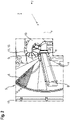
Fig. 2 ist schematisch eine Ansicht einer Siebeinrichtung 5 gemäß einer alternativen Ausführungsform dargestellt. Ein im Wesentlichen trichterförmiges Sieb 6 ist ortsfest an einem Rahmen 13 im Motorraum der Erntemaschine 1 angeordnet. Die zumindest eine Absaugdüse 8 ist um die Achse 7 rotierend angeordnet. Die zumindest eine Absaugdüse 8 weist einen länglichen Hohlkörper 14 mit zumindest einer Absaugöffnung 16 auf, die sich abschnittsweise in Längsrichtung x, d.h. bezogen auf die Achse 7 in radialer Richtung, und in Querrichtung y des Hohlkörpers 14 erstreckt. Die zumindest eine Absaugöffnung 16 ist durch zumindest einen Luftkanal 17 im Inneren des Hohlkörpers 14 mit dem an dem Hohlkörper 14 angeordneten Anschluss 9 zur Verbindung mit der Unterdruckquelle 11 verbunden. Die zumindest eine Absaugöffnung 16 ist dem Sieb 6 der Siebeinrichtung 5 zugewandt angeordnet. Die Absaugdüse 8 kann in Querrichtung y gesehen über ihre gesamte Länge eine im Wesentlichen konstante Breite B aufweisen. - Die Darstellung in
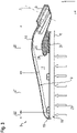
Fig. 3 zeigt eine erste Ausführungsform der Absaugdüse 8 der Siebeinrichtung 5 im Längsschnitt. Der Luftkanal 17 im Inneren des Hohlkörper 14 erstreckt sich von dem Anschluss 9, an dem die Zuleitung 10 angeordnet wird, bis zum äußeren Ende 18 der Absaugdüse 8. Der Hohlkörper 14 weist ausgehend von dem äußeren Ende 18 der Absaugdüse 8 in Längsrichtung x des Hohlkörpers 14 bis zu dem Anschluss 9 einen in Hochrichtung z des Hohlkörpers 14 zunehmenden Querschnittsverlauf auf. Eine der zumindest einen Absaugöffnung 16 zugewandte Innenkontur 19 des zumindest einen Luftkanals 17 weist eine im Wesentlichen einem Tragflächenprofil entsprechende Kontur auf. Die Innenkontur 19 ist der zu der zumindest einen Absaugöffnung 16 parallel verlaufende Bereich im Inneren des Hohlkörpers 14, durch den sich der Querschnittsverlauf in Hochrichtung z verändern lässt. Die einem Tragflächenprofil entsprechende Innenkontur 19 führt zu einer Variation des von dem Absaugluftstrom durchströmten Querschnitts im Inneren der Absaugdüse 8, so dass bei einem vorgegebenen Absaugluftvolumenstrom in einem zum Anschluss 9 weiter beabstandeten Abschnitt der zumindest einen Absaugöffnung 16 eine Erhöhung der Strömungsgeschwindigkeit des Absaugluftstroms bewirkt wird. Hierdurch kann eine Erhöhung der Absauggeschwindigkeit erreicht werden, ohne zugleich den Absaugluftvolumenstrom zu erhöhen. Die Funktionssicherheit der Kühleinrichtung 3 wird durch die verbesserte Absaugung des Siebes 6 erhöht. - Die Innenkontur 19 des zumindest einen Luftkanals 17 der Absaugdüse 8 weist ausgehend von dem Anschluss 9 zunächst einen ersten Bereich 20 mit einem abschnittsweise konvexen Verlauf auf, der in einen zweiten Bereich 21 mit einem abschnittsweise konkaven Verlauf übergeht und zu dem äußeren Ende 18 des Hohlkörpers 14 hin in einen dritten Bereich 22 mit einem konvexen Verlauf übergeht. Außenseitig kann die Absaugdüse 8 eine von der Innenkontur 19 abweichenden Konturenverlauf aufweisen.
- Mit Pfeilen 23 ist die Ansaugrichtung eines Absaugluftstroms bezeichnet, in welcher die zumindest eine dem - lediglich angedeuteten - Sieb 6 der Siebeinrichtung 5 zugewandte Absaugöffnung 16 der Absaugdüse 8 den Absaugluftstrom zusammen mit Partikeln, die sich auf der Sieboberfläche ablagern, ein- bzw. absaugt. Die Erstreckung der Absaugöffnung 16 in Längsrichtung beschreibt die wirksame Gesamtabsauglänge der Absaugdüse 8, über welche die Sieboberfläche des Siebes 6 abgesaugt wird.
- Im ersten Bereich 20 ist der vertikale Abstand zwischen der Absaugöffnung 16 und der Innenkontur 19 durch einen sich abschnittsweise in Längsrichtung x erstreckenden Profilabschnitt 24 reduziert. Der Profilabschnitt 24 erstreckt sich in Querrichtung y gesehen über die Breite der Absaugdüse 8. Der Profilabschnitt 24 bildet somit eine geschlossene Fläche, die sich in Querrichtung des Hohlkörpers 14 erstreckt.
- Der Profilabschnitt 24 weist dabei eine mit dem Verlauf des ersten Bereichs 20 korrespondierende Kontur seiner der Innenkontur 19 zugewandten Oberseite 25 auf. Die Kontur der Oberseite 25 ist nach außen gewölbt, d.h. erstreckt sich in Richtung des ersten Bereichs 20 der Innenkontur 19. Ausgehend vom Bereich des Anschlusses 9 steigt der Verlauf der Kontur der Oberseite 25 zunächst an, um nach einem Wendepunkt abzufallen. Ein dem äußeren Ende 18 der Absaugdüse 8 zugewandter stirnseitiger Abschnitt 26 ist als eine Nase mit kleinem Krümmungsradius ausgeführt, um Verwirbelungen an dem stirnseitigen Abschnitt 26 zu minimieren oder zu vermeiden. Durch den Profilabschnitt 24 wird, über dessen abschnittsweise Erstreckung in Längsrichtung x, im ersten Bereich 20 eine Querschnittsreduzierung bewirkt, wodurch die Strömungsgeschwindigkeit des Absaugluftstroms zunächst zunimmt.
- Unmittelbar hinter dem Profilabschnitt 24 kommt im es auslaufenden ersten Bereich 20 aufgrund der Zunahme des Abstands zwischen der Absaugöffnung 16 und der Innenkontur 19 zu einer sprunghaften Erweiterung des Querschnitts. Dadurch sinkt die Strömungsgeschwindigkeit des Absaugluftstroms.
- In dem sich in Längsrichtung x gesehen anschließenden zweiten Bereich 21 nimmt der Querschnitt kontinuierlich ab, wodurch es zu einer Zunahme der Strömungsgeschwindigkeit des Absaugluftstroms kommt. Der zweite Bereich 21 erstreckt sich dabei in Längsrichtung x im Wesentlichen über ein Drittel bis zur Hälfte der Längsausdehnung des Luftkanals 17. Mit zunehmendem Abstand zu dem ersten Bereich 20 erhöht sich die Strömungsgeschwindigkeit des Absaugluftstroms, wodurch das Absaugen vom sich auf der Oberfläche des Siebes 6 ablagernden anhaftenden Partikeln, insbesondere im distalen Absaugbereich der Absaugdüse 8, verbessert wird.
- Der dritte Bereich 22 bildet das äußere Ende 18 der Absaugdüse 8. Der dritte Bereich 22 ist der kürzeste und weist zudem den geringsten Querschnitt auf. Der konkave Verlauf des dritten Abschnitts 22 bildet eine stirnseitige Begrenzung des Hohlkörpers 14 aus. Hier wird der Absaugluftstrom vorrangig umgelenkt.
- In
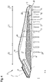
Fig. 4 ist schematisch eine weitere Ausführungsform der Absaugdüse 8 für die Siebeinrichtung 5 gemäßFig. 2 dargestellt. Die inFig. 4 gezeigte Absaugdüse 8 ist in einer gegenüber der Darstellung gemäßFig. 3 um 180° zur Hochrichtung z gedrehten Anordnung dargestellt. Der grundsätzliche Aufbau ist identisch mit der inFig. 3 dargestellten Absaugdüse 8, so dass die dort verwendeten Bezugszeichen für identische Komponenten und Bauteile beibehalten werden. Gemäß dieser zweiten Ausführungsform der Absaugdüse 8 ist ein abweichend ausgeführter Profilabschnitt 27 vorgesehen. Der Profilabschnitt 27 erstreckt sich in Längsrichtung x nahezu über die gesamte Länge der der Absaugöffnung 16. Der Profilabschnitt 27 weist ebenfalls eine zunächst mit dem ersten Bereich 20 korrespondieren Verlauf der Kontur seiner der Innenkontur 19 zugewandten Oberseite 28 auf, welche im ersten Bereich 20 in einen im Wesentlichen zur Absaugöffnung 16 parallelen Verlauf übergeht. Der Profilabschnitt 27 erstreckt sich nahezu bis an das Ende des zweiten Bereichs 21 der Innenkontur 19, so dass eine spaltförmige, sich in Querrichtung y erstreckende Öffnung 29 verbleibt. Durch den zur Absaugöffnung 16 im Wesentlichen parallelen Verlauf der Oberseite 28 des Profilabschnittes 27 wird der durchströmte Querschnitt zwischen der Innenkontur 19 und der Oberseite 28 in Längsrichtung x kontinuierlich reduziert. Somit weist der Absaugluftstrom Übergang vom zweiten Bereich 21 in den dritten Bereich 22 sowie im dritten Bereich 22 die höchste Strömungsgeschwindigkeit auf. - Ein dem äußeren Ende 18 der Absaugdüse 8 zugewandter stirnseitiger Abschnitt 30 des Profilabschnitts 27 ist ebenfalls als eine Nase mit kleinem Krümmungsradius ausgeführt. Um den stirnseitigen Abschnitt 30 des Profilabschnitts 27 wird der durch die Absaugöffnung 16 angesaugte Absaugluftstrom umgelenkt. Mit seiner Unterseite 31 ist der Profilabschnitt 27 der Absaugöffnung 16 zugewandt. Die Kontur der Unterseite 31 des Profilabschnitts 27 weist, vom Anschluss 9 ausgehend gesehen, einen in Längsrichtung x im Wesentlichen rampenförmig ansteigenden Verlauf auf. Ein sich zwischen der Absaugöffnung 16 und der Unterseite 31 des Profilabschnitts 27 ausgebildeter Abstand 32 nimmt in Längsrichtung x zu. Durch die Ausgestaltung der Unterseite 31 des Profilabschnitts 27 wird erreicht, dass auch im dem Anschluss 9 zugewandten Bereich der Absaugdüse 8 eine adäquate Saugwirkung erreicht wird. Am Ende der Unterseite 31 im stirnseitigen Abschnitt 30 ist der Abstand 32 am größten. Der durch die Ausgestaltung des Profilabschnitts 27 im Übrigen erreichte Effekt entspricht im Wesentlichen dem gemäß der Ausführungsform gemäß
Fig. 3 . Die Absaugung erfolgt über die gesamte Längsausdehnung der Absaugöffnung 16 mit einem ungeteilten Absaugluftstrom. - Ausgehend von dem Anschluss 9 nimmt die Strömungsgeschwindigkeit des Absaugluftstromes in Längsrichtung x zwischen der Oberseite 28 des Profilabschnitts 27 und der Innenkontur 19 aufgrund der dem Tragflächenprofil entsprechende Kontur zu, während auf der Unterseite 30 des Profilabschnitts 27 ausgehend von dem dem Anschluss 9 nächstliegenden Bereich des Profilabschnitts 27 in Längsrichtung x eine Abnahme der Strömungsgeschwindigkeit des Absaugluftstromes durch den rampenförmigen Verlauf der Unterseite 30 bewirkt wird.
- Die Darstellungen in
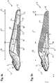
Fig. 5a und 5b zeigen schematisch eine weitere Ausführungsform einer Absaugdüse 8 für eine Siebeinrichtung gemäßFig. 2 im Längsschnitt. Die Schnittebenen sind dabei in Querrichtung y versetzt zueinander. So zeigtFig. 5a einen in Querrichtung y weiter vorne liegenden Bereich undFig. 5b einen in Querrichtung y weiter nach hinten versetzt liegenden Bereich der Absaugdüse 8. Die äußere Gestalt und Form der Absaugdüse 8 entspricht im Wesentlichen derjenigen der vorangehend beschriebenen und in denFig. 2 bis 4 dargestellten Ausführungsformen der Absaugdüse 8. - Die Absaugdüse 8 in
Fig. 5a und 5b weist zwei Absaugöffnungen 33, 34 auf, welche in Längsrichtung x gesehen hintereinander angeordnet sind. Die beiden Absaugöffnungen 33, 34 erstrecken sich jeweils abschnittsweise in Längsrichtung x der Absaugdüse 8. Die beiden Absaugöffnungen 33, 34 können, wie inFig. 6 schematisch dargestellt, zudem in Querrichtung y versetzt zueinander angeordnet sein. - Mit 33 ist eine vordere Absaugöffnung bezeichnet, deren Abstand zum Anschluss 9 in Längsrichtung x gesehen größer ist als der Abstand der hinteren Absaugöffnung 34. Die jeweilige Absaugöffnung 33, 34 weist in Längsrichtung x gesehen eine Erstreckung auf, die jeweils im Wesentlichen der halben Längsausdehnung einer wirksamen Gesamtabsauglänge der Absaugdüse 8 entspricht. Die Gesamtabsauglänge entspricht der von der Absaugdüse 8 überstrichenen radialen Erstreckung des Siebes 6, innerhalb der Partikel von der Oberfläche des Siebes 6 abgesaugt werden. Die Gesamtabsauglänge ist dabei geringer, als die Gesamtlänge der Absaugdüse 8.
- Der Absaugluftstrom wird durch die Absaugdüse 8 aufgeteilt und durch zwei separate Luftkanäle 35, 36 geführt, welche jeweils eine der Absaugöffnung 33, 34 mit dem Anschluss 9 fluidleitend verbindet. Die Luftkanäle 35, 36 sind in Hochrichtung z gesehen in abschnittsweise voneinander abweichend verlaufenden, insbesondere übereinanderliegenden, Ebenen im Inneren der Absaugdüse 8 angeordnet.
- In
Fig. 5a ist die vordere Absaugöffnung 33, d.h. die sich von dem äußeren Ende 18 abschnittsweise in Richtung des Anschlusses 9 erstreckende Absaugöffnung 33, durch den Luftkanal 35 mit dem Anschluss 9 verbunden. Die der vorderen Absaugöffnung 33 zugewandte Innenkontur 19 der Absaugdüse 8 ist identisch mit derjenigen der vorangehend beschriebenen Ausführungsformen. - Der Luftkanal 35, der sich über die hintere Absaugöffnung 34 hinweg, d.h. die sich von dem Anschluss 9 bis zum Beginn der vorderen Absaugöffnung 33 erstreckende Absaugöffnung 34, erstreckt, verläuft bis zum äußeren Ende 18 der Absaugdüse 8. D.h. der Luftkanal 35 erstreckt sich über die gesamte Längsausdehnung der wirksamen Gesamtabsauglänge. Ausgehend von dem Anschluss 9 erstreckt sich ein nasenförmiger Profilabschnitt 37 in Richtung der vorderen Absaugöffnung 33 und überlappt diese abschnittsweise. Der Profilabschnitt 37 weist eine der Innenkontur 19 zugewandte Oberseite 38, einen dem äußeren Ende 18 der Absaugdüse 8 zugewandten stirnseitigen Abschnitt 39 sowie eine der vorderen Absaugöffnung 33 zugewandte Unterseite 40 auf.
- Der Abstand zwischen dem stirnseitigen Abschnitt 39 und dem äußeren Ende 18 der der Absaugdüse 8 ist geringer als die Länge der vorderen Absaugöffnung 33. Die Unterseite 40 überlappt die vordere Absaugöffnung 33, wobei sich der Abstand zwischen der Unterseite 40 und der vorderen Absaugöffnung 33 in Längsrichtung x, zum äußeren Ende 18 hin vergrößert.
- Gemäß der
Fig. 5b ist die hintere Absaugöffnung 34, d.h. die sich von dem Anschluss 9 abschnittsweise in Richtung des äußeren Ende 18 erstreckende Absaugöffnung 34, durch den Luftkanal 36 mit dem Anschluss 9 verbunden. Der Luftkanal 36 erstreckt sich im Wesentlichen bis zum Beginn der vorderen Absaugöffnung 33, d.h. der dem Anschluss 9 zugewandten Seite der vorderen Absaugöffnung 33. Der Luftkanal 36 weist eine der hinteren Absaugöffnung 34 zugewandte Innenkontur 41 auf, die ebenfalls eine im Wesentlichen einem Tragflächenprofil entsprechende Kontur aufweist wie die Innenkontur 19 des Luftkanals 35. - Die gemäß der in den
Fig. 5a und 5b dargestellten Ausführungsform ausgeführte Absaugdüse 8 weist somit zwei Luftkanäle 35, 36 unterschiedlicher Länge auf, so dass sich die Gutmenge an abzufördernden Partikeln im Absaugluftstrom aufteilt. Durch unterschiedliche Öffnungsquerschnitte der Luftkanäle 35, 36 im Bereich des Anschlusses 9 kann die Aufteilung des Absaugluftstroms zusätzlich beeinflusst werden. Dabei kann der Anteil des Absaugluftstroms, der durch die vordere Absaugöffnung 33 abgesaugt wird, größer sein als der Anteil, der durch die hintere Absaugöffnung 34 abgesaugt wird. - In
Fig. 6 ist schematisch und stark vereinfacht, die Ausführungsform der Absaugdüse 8 gemäßFig. 5a und 5b in einer Seitenansicht dargestellt. Die Erstreckung der vorderen Absaugöffnung 33 und/oder der hinteren Absaugöffnung 34 und ihrer jeweiligen Luftkanäle 35,36 kann derart gewählt sein, dass der Abstand im mittleren Bereich der Absaugdüse 8 zwischen diesen minimiert ist. - In
Fig. 7 ist schematisch und stark vereinfacht, eine weitere Ausführungsform einer Absaugdüse 8 in einer Ansicht von unten dargestellt. Der Aufbau entspricht im Wesentlichen der Ausführungsform gemäß denFig. 5a und 5b , wobei die Luftkanäle 35, 36, in Querrichtung y gesehen, hintereinander und nebeneinanderliegend angeordnet sind. Die jeweilige Erstreckung der hinteren Absaugöffnung 34 und der vorderen Absaugöffnung 33 kann derart gewählt sein, dass ein sich überlappender Absaugbereich 42 der beiden Absaugöffnungen 33, 34 im Wesentlichen in der Mitte der Ansaugdüse 8 ausbildet. Im Übrigen sind die Luftkanäle 35, 36 entsprechend der Ausführungsform gemäß denFig. 5a und 5b ausgebildet. -
Fig. 8 zeigt schematisch und exemplarisch eine Ausführungsform, bei welcher zwei Absaugdüsen 8 gemeinsam um die Achse 7 rotierend angeordnet sind. Die Absaugdüsen 8 sind entsprechend der Ausführungsform gemäßFig. 7 ausgebildet und einander gegenüberliegend, um 180° versetzt, angeordnet. Die Anschlüsse 9 der beiden Absaugdüsen 8 sind miteinander in der Weise verbunden, dass lediglich eine Zuleitung 10 im Wesentlichen koaxial zur Achse 7 anschließbar ist. - Gemäß einer weiteren Ausgestaltung kann der Anschluss 9 mittig an dem Hohlkörper 14 der Absaugdüse 8 angeordnet sein. Von dem mittig angeordneten Anschluss 9 können sich, spiegelbildlich ausgeführt, zu beiden Seiten Luftkanäle erstrecken, welche entsprechend der in
Fig. 3 dargestellten Ausführungsform ausgeführt sind, jedoch jeweils eine Erstreckung in Querrichtung y aufweisen, die etwa der halben Länge des Luftkanals 17 entsprecht Eine singuläre Absaugöffnung erstreckt sich nahezu über die gesamte Erstreckung der Absaugdüse 8 in Längsrichtung und weist auch im Bereich des mittig angeordneten Anschlusses 9 keine Unterbrechung auf. Die beidseitig des Anschlusses 9 der durchgehenden Absaugöffnung zugewandten Innenkonturen des spiegelsymmetrisch ausgeführten Hohlkörpers weisen eine im Wesentlichen einem Tragflächenprofil entsprechende Kontur auf. Der zusätzliche Vorteil der mittigen Anordnung des mittig angeordneten Anschlusses 9 besteht darin, dass die Luftförderwege verkürzt sind. Diese Ausführungsform der Absaugdüse 8 ist insbesondere bei einem sich relativ zur Absaugdüse 8 bewegenden, insbesondere rotierenden, Sieb 6 sinnvoll. - In
Fig. 9 ist schematisch und exemplarisch eine weitere Ausführungsform einer Absaugdüse 8 in perspektivischer Ansicht von unten dargestellt. Diese Ausführungsform der Absaugdüse 8 unterscheidet sich von der inFig. 3 dargestellten Ausführungsform zum einen durch die abweichende Anordnung des Anschlusses 9. Während der Anschluss 9 gemäß der Ausführungsform nachFig. 3 am äußeren Ende des Hohlkörpers 14 angeordnet ist, ist bei der inFig. 9 gezeigten Ausführungsform eine Positionierung des Anschlusses 9 im mittleren Bereich der Absaugdüse 8 vorgesehen. Zum anderen weist die Absaugdüse 8 keinen sich abschnittsweise in Längsrichtung x erstreckenden Profilabschnitt auf. - Der Anschluss 9 ist bezogen auf die Mitte der Absaugöffnung 16 der Absaugdüse 8 außermittig angeordnet. Insbesondere ist der Anschluss 9 näher am äußeren Ende 18 des Hohlkörpers 14 angeordnet. Zudem ist der Anschluss 9 im Wesentlichen senkrecht zum Verlauf der Innenkontur 19 angeordnet, d.h. der Anschluss 9 ist an einer Seitenwandung 43 an der Außenseite des Hohlkörpers 14 ausgebildet. Die außermittige Anordnung des Anschlusses 9 gemäß dieser Ausführungsform hat den Vorteil, dass die Absauggeschwindigkeit im distalen Bereich der Absaugdüse 8 erhöht ist. Dadurch wird, bezogen auf den Mittelpunkt des Siebes 6, in den radial entfernteren Bereichen des Siebes 6 das Ablösen von Anhaftungen verbessert. Zudem wird bei dieser Ausführungsform eine gleichmäßige Absauggeschwindigkeit in Längsrichtung x der Absaugdüse 8 erreicht.
-
1 Erntemaschine 34 Absaugöffnung 2 Antriebseinheit 35 Luftkanal 3 Kühleinrichtung 36 Luftkanal 4 Sauggebläse 37 Profilabschnitt 5 Siebeinrichtung 38 Oberseite 6 Sieb 39 Stirnseitiger Abschnitt 7 Achse 40 Unterseite 8 Absaugdüse 41 Innenkontur 9 Anschluss 42 Absaugbereich 10 Zuleitung 43 Seitenwandung 11 Unterdruckquelle B Breite 12 Nachbeschleuniger x Längsrichtung 13 Rahmen y Querrichtung 14 Hohlkörper z Hochrichtung 15 Sauggebläse 16 Absaugöffnung 17 Luftkanal 18 Äußeres Ende von 8 19 Innenkontur 20 Ersten Bereich 21 Zweiten Bereich 22 Dritten Bereich 23 Ansaugrichtung 24 Profilabschnitt 25 Oberseite 26 Stirnseitiger Abschnitt 27 Profilabschnitt 28 Oberseite 29 Öffnung 30 Stirnseitiger Abschnitt 31 Unterseite 32 Abstand 33 Absaugöffnung
Claims (15)
- Siebeinrichtung (5) mit zumindest einer Absaugdüse (8), welche einen länglichen Hohlkörper (14) mit zumindest einer Absaugöffnung (16, 33, 34), die sich abschnittsweise in Längsrichtung (x) und Querrichtung (y) des Hohlkörpers (14) erstreckt, und durch zumindest einen Luftkanal (17, 35, 36) im Inneren des Hohlkörpers (14) mit einem an dem Hohlkörper (14) angeordneten Anschluss (9) zur Verbindung mit einer Unterdruckquelle (4, 15) verbunden ist, aufweist, wobei die zumindest eine Absaugöffnung (9) einem Sieb (6) der Siebeinrichtung (5) zugewandt angeordnet ist, dadurch gekennzeichnet, dass der zumindest eine Luftkanal (17, 35, 36) ausgehend von einem äußeren Ende (18) der Absaugdüse (8) in Richtung des Anschlusses (9) einen in Hochrichtung (z) zunehmenden Querschnittsverlauf aufweist, wobei eine der zumindest einen Absaugöffnung (16, 33, 34) zugewandte Innenkontur (19, 41) des zumindest einen Luftkanals (17, 35, 36) eine im Wesentlichen einem Tragflächenprofil entsprechende Kontur aufweist.
- Siebeinrichtung (5) nach Anspruch 1, dadurch gekennzeichnet, dass die Innenkontur (19, 41) des zumindest einen Luftkanals (17, 35, 36) ausgehend von dem Anschluss (9) zunächst einen ersten Bereich (21) mit einem abschnittsweise konvexen Verlauf aufweist, der in einen zweiten Bereich (22) mit einem abschnittsweise konkaven Verlauf übergeht und zu dem äußeren Ende (18) des Hohlkörpers (14) hin in einen dritten Bereich (23) mit einem konvexen Verlauf übergeht.
- Siebeinrichtung (5) nach Anspruch 2, dadurch gekennzeichnet, dass sich der zweite Bereich (21) in Längsrichtung (x) im Wesentlichen über ein Drittel bis zur Hälfte der Längsausdehnung zumindest einen Luftkanals (17, 35, 36) erstreckt.
- Siebeinrichtung (5) nach einem der Ansprüche 1 bis 3, dadurch gekennzeichnet, dass sich ein Profilabschnitt (24, 27, 37) ausgehend von dem Anschluss (9) abschnittsweise in Längsrichtung (x) des Hohlkörpers (14) erstreckt.
- Siebeinrichtung (5) nach Anspruch 4, dadurch gekennzeichnet, dass eine der Innenkontur (19, 41) zugewandte Oberseite (25, 28, 38) des Profilabschnitts (24, 27, 37) einen mit dem ersten Bereich (20) im Wesentlichen korrespondierenden Verlauf aufweist.
- Siebeinrichtung (5) nach einem der Ansprüche 1 bis 5, dadurch gekennzeichnet, dass die Absaugdüse (8) zwei Absaugöffnungen (33, 34) aufweist, die in Längsrichtung (x) hintereinander angeordnet und durch separate Luftkanäle (35, 36) mit dem Anschluss (9) verbunden sind.
- Siebeinrichtung (5) nach Anspruch 6, dadurch gekennzeichnet, dass die beiden Absaugöffnungen (33, 34) in Längsrichtung (x) gesehen eine Erstreckung aufweisen, die jeweils im Wesentlichen der halben Längsausdehnung einer wirksamen Gesamtabsauglänge der Absaugdüse (8) entspricht.
- Siebeinrichtung (5) nach Anspruch 6 oder 7, dadurch gekennzeichnet, dass die beiden Absaugöffnungen (33, 34) in Längsrichtung (x) gesehen seitlich versetzt zueinander angeordnet sind.
- Siebeinrichtung (5) nach einem der vorangehenden Ansprüche, dadurch gekennzeichnet, dass zwei Absaugdüsen (8) einander gegenüberliegend angeordnet sind und einen gemeinsamen Anschluss (9) aufweisen.
- Siebeinrichtung (5) nach einem der Ansprüche 1 bis 8, dadurch gekennzeichnet, dass der Anschluss (9) im Wesentlichen mittig an dem Hohlkörper (14) der Absaugdüse (8) angeordnet ist, und dass ausgehend von dem mittig angeordneten Anschluss (9) sich zu beiden Seiten spiegelbildlich ausgeführte Luftkanäle (17) erstrecken, die eine durchgehende Absaugöffnung (16) mit dem Anschluss (9) verbinden.
- Siebeinrichtung (5) nach einem der Ansprüche 1 bis 8, dadurch gekennzeichnet, dass der Anschluss (9) im Wesentlich mittig an dem Hohlkörper (14) der Absaugdüse (8) angeordnet ist, und dass ausgehend von dem mittig angeordneten Anschluss (9) sich zu beiden Seiten spiegelbildlich ausgeführte Luftkanäle (17, 35, 36) erstrecken, die mehrere Absaugöffnungen (16, 33, 34) mit dem Anschluss (9) verbinden.
- Siebeinrichtung (5) nach einem der Ansprüche 1 bis 5, dadurch gekennzeichnet, dass der Anschluss (9) außermittig und sich im Wesentlichen senkrecht zu einer Seitenwandung (43) des Hohlkörpers (14) erstreckend angeordnet ist.
- Siebeinrichtung (5) nach einem der vorangehenden Ansprüche, dadurch gekennzeichnet, dass das Sieb (6) rotierend angetrieben ist und die Absaugdüse (8) relativ zu dem Sieb (6) feststehend angeordnet ist.
- Siebeinrichtung (5) nach einem der vorangehenden Ansprüche, dadurch gekennzeichnet, dass das Sieb (6) feststehend angeordnet ist und die Absaugdüse (8) gegenüber dem Sieb (6) relativbeweglich ist.
- Selbstfahrende Erntemaschine (1) mit einer ein Sieb (6) umfassenden Siebeinrichtung (5), wobei dem Sieb (6) eine Absaugdüse (8) zugeordnet ist, deren zumindest eine im Wesentlichen schlitzförmige Absaugöffnung (16, 33, 34) dem Sieb (6) zugewandt positioniert ist, dadurch gekennzeichnet, dass die Siebeinrichtung (5) nach einem der vorangehenden Ansprüche ausgebildet ist.
Applications Claiming Priority (1)
| Application Number | Priority Date | Filing Date | Title |
|---|---|---|---|
| DE102021111281.8A DE102021111281A1 (de) | 2021-04-30 | 2021-04-30 | Siebeinrichtung mit zumindest einer Absaugdüse |
Publications (1)
| Publication Number | Publication Date |
|---|---|
| EP4082323A1 true EP4082323A1 (de) | 2022-11-02 |
Family
ID=78851309
Family Applications (1)
| Application Number | Title | Priority Date | Filing Date |
|---|---|---|---|
| EP21214229.3A Pending EP4082323A1 (de) | 2021-04-30 | 2021-12-14 | Siebeinrichtung mit zumindest einer absaugdüse |
Country Status (3)
| Country | Link |
|---|---|
| US (1) | US12284941B2 (de) |
| EP (1) | EP4082323A1 (de) |
| DE (1) | DE102021111281A1 (de) |
Families Citing this family (1)
| Publication number | Priority date | Publication date | Assignee | Title |
|---|---|---|---|---|
| CN119999453B (zh) * | 2025-02-17 | 2025-11-07 | 江苏大学 | 一种自走式西兰花收获机底盘装置和收获机 |
Citations (4)
| Publication number | Priority date | Publication date | Assignee | Title |
|---|---|---|---|---|
| US20100006361A1 (en) * | 2008-07-14 | 2010-01-14 | Vandike Nathan R | Agricultural machine having dedicated multi-section fan unit |
| US20170107893A1 (en) * | 2014-06-02 | 2017-04-20 | Cnh Industrial America Llc | Suction Wand for a Cooler Box |
| EP3650103A1 (de) * | 2018-11-09 | 2020-05-13 | CNH Industrial Belgium N.V. | Saugsonde für einen nicht kreisförmigen luftfilter |
| EP3696385A2 (de) * | 2019-02-12 | 2020-08-19 | CLAAS Selbstfahrende Erntemaschinen GmbH | Kühleinrichtung für eine landwirtschaftliche arbeitsmaschine |
Family Cites Families (13)
| Publication number | Priority date | Publication date | Assignee | Title |
|---|---|---|---|---|
| US2601704A (en) * | 1950-07-25 | 1952-07-01 | Hardwicke Etter Co | Screen cleaning apparatus |
| US4036613A (en) * | 1976-08-25 | 1977-07-19 | Woods Metal Company, Inc. | Rotary sweep arm for self-cleaning filter apparatus |
| US5183487A (en) * | 1992-04-24 | 1993-02-02 | Deere & Company | Trash handling apparatus for a self-cleaning rotary screen |
| US5466271A (en) * | 1994-04-29 | 1995-11-14 | Horvat; Ivan J. | Pre-filter with rotating nozzle |
| US5466189A (en) * | 1994-08-18 | 1995-11-14 | Deere & Company | Cleaner for a rotating screen on a harvester |
| US8097050B2 (en) * | 2008-02-26 | 2012-01-17 | Cnh America Llc | Rotary vacuum apparatus for air screen |
| US8312594B2 (en) * | 2008-06-27 | 2012-11-20 | Nilfisk-Advance, Inc. | Carpet cleaning wand having uniform air flow distribution |
| US8974564B2 (en) * | 2011-07-15 | 2015-03-10 | Deere & Company | Screen cleaning system |
| DE102018103373A1 (de) | 2018-02-15 | 2019-08-22 | Claas Selbstfahrende Erntemaschinen Gmbh | Mähdrescher sowie Verfahren zu dessen Betrieb |
| DE102018104286A1 (de) | 2018-02-26 | 2019-08-29 | Claas Selbstfahrende Erntemaschinen Gmbh | Selbstfahrender Feldhäcksler |
| US10995772B2 (en) * | 2019-03-21 | 2021-05-04 | Cnh Industrial America Llc | Agricultural harvester cooler box with debris guard |
| US11376946B2 (en) * | 2020-02-24 | 2022-07-05 | Deere & Company | Magnetic couplers for shaft assembly |
| US11506111B2 (en) * | 2020-04-08 | 2022-11-22 | Deere & Company | Work vehicle having an intake cleaning system with an alignment mechanism |
-
2021
- 2021-04-30 DE DE102021111281.8A patent/DE102021111281A1/de active Pending
- 2021-12-14 EP EP21214229.3A patent/EP4082323A1/de active Pending
-
2022
- 2022-04-29 US US17/732,835 patent/US12284941B2/en active Active
Patent Citations (5)
| Publication number | Priority date | Publication date | Assignee | Title |
|---|---|---|---|---|
| US20100006361A1 (en) * | 2008-07-14 | 2010-01-14 | Vandike Nathan R | Agricultural machine having dedicated multi-section fan unit |
| US20170107893A1 (en) * | 2014-06-02 | 2017-04-20 | Cnh Industrial America Llc | Suction Wand for a Cooler Box |
| EP3149305B1 (de) | 2014-06-02 | 2018-05-30 | CNH Industrial Belgium N.V. | Saugarm für einen kühlerkasten |
| EP3650103A1 (de) * | 2018-11-09 | 2020-05-13 | CNH Industrial Belgium N.V. | Saugsonde für einen nicht kreisförmigen luftfilter |
| EP3696385A2 (de) * | 2019-02-12 | 2020-08-19 | CLAAS Selbstfahrende Erntemaschinen GmbH | Kühleinrichtung für eine landwirtschaftliche arbeitsmaschine |
Also Published As
| Publication number | Publication date |
|---|---|
| US12284941B2 (en) | 2025-04-29 |
| US20220346314A1 (en) | 2022-11-03 |
| DE102021111281A1 (de) | 2022-11-03 |
Similar Documents
| Publication | Publication Date | Title |
|---|---|---|
| EP3753393B1 (de) | Selbstfahrender mähdrescher | |
| DE2922607A1 (de) | Geblaese fuer die reinigungsvorrichtung von maehdreschern | |
| DE10012766B4 (de) | Reinigungseinrichtung für ein Sieb und Fahrzeug mit Reinigungseinrichtung | |
| EP4056759A1 (de) | Strassenfertiger mit absaugeinrichtung | |
| EP3208466B1 (de) | Reinigungsgebläse mit kunststoffgehäuse sowie verwendung eines rotationsformverfahrens zur herstellung eines einteiligen gehäuses | |
| EP1733610B1 (de) | Radialgebläse für eine Reinigungseinrichtung für einen Mähdrescher | |
| EP4223100B1 (de) | Selbstfahrender mähdrescher | |
| EP1214873B1 (de) | Einlauf einer Axialdreschmaschine | |
| DE102021111281A1 (de) | Siebeinrichtung mit zumindest einer Absaugdüse | |
| EP3906774B1 (de) | Mähdrescher | |
| DE19729938A1 (de) | Reinigungsverfahren einer Zuckerrohrerntemaschine sowie nach diesem Verfahren arbeitende Zuckerrohrerntemaschine | |
| EP3903557B1 (de) | Selbstfahrender mähdrescher sowie verfahren zur ernte | |
| EP3586595B1 (de) | Kühlerkorb mit einer reinigungsvorrichtung | |
| EP1378161B1 (de) | Wind-Siebeinrichtung | |
| EP3207788B1 (de) | Reinigungseinrichtung | |
| EP4000378B1 (de) | Landwirtschaftliche arbeitsmaschine mit einer trommel | |
| EP4696130A1 (de) | Mähdrescher | |
| EP3216340B1 (de) | Mähdrescher | |
| EP1961289A1 (de) | Landwirtschaftliche Arbeitsmaschine | |
| EP2997813B1 (de) | Mähdrescher | |
| DE102023131103A1 (de) | Gebläsezusammenbau für eine Reinigungseinrichtung eines Mähdreschers | |
| EP4338580B1 (de) | Selbstfahrender mähdrescher | |
| EP4696129A2 (de) | Mähdrescher | |
| EP4491006A1 (de) | Selbstfahrender mähdrescher | |
| EP4487675A1 (de) | Selbstfahrender mähdrescher |
Legal Events
| Date | Code | Title | Description |
|---|---|---|---|
| PUAI | Public reference made under article 153(3) epc to a published international application that has entered the european phase |
Free format text: ORIGINAL CODE: 0009012 |
|
| STAA | Information on the status of an ep patent application or granted ep patent |
Free format text: STATUS: THE APPLICATION HAS BEEN PUBLISHED |
|
| AK | Designated contracting states |
Kind code of ref document: A1 Designated state(s): AL AT BE BG CH CY CZ DE DK EE ES FI FR GB GR HR HU IE IS IT LI LT LU LV MC MK MT NL NO PL PT RO RS SE SI SK SM TR |
|
| STAA | Information on the status of an ep patent application or granted ep patent |
Free format text: STATUS: REQUEST FOR EXAMINATION WAS MADE |
|
| 17P | Request for examination filed |
Effective date: 20230502 |
|
| RBV | Designated contracting states (corrected) |
Designated state(s): AL AT BE BG CH CY CZ DE DK EE ES FI FR GB GR HR HU IE IS IT LI LT LU LV MC MK MT NL NO PL PT RO RS SE SI SK SM TR |
|
| P01 | Opt-out of the competence of the unified patent court (upc) registered |
Effective date: 20230516 |
|
| GRAP | Despatch of communication of intention to grant a patent |
Free format text: ORIGINAL CODE: EPIDOSNIGR1 |
|
| STAA | Information on the status of an ep patent application or granted ep patent |
Free format text: STATUS: GRANT OF PATENT IS INTENDED |