EP4082315A1 - Work vehicle - Google Patents
Work vehicle Download PDFInfo
- Publication number
- EP4082315A1 EP4082315A1 EP20908317.9A EP20908317A EP4082315A1 EP 4082315 A1 EP4082315 A1 EP 4082315A1 EP 20908317 A EP20908317 A EP 20908317A EP 4082315 A1 EP4082315 A1 EP 4082315A1
- Authority
- EP
- European Patent Office
- Prior art keywords
- automatic operation
- working
- monitored information
- vehicle body
- monitoring
- Prior art date
- Legal status (The legal status is an assumption and is not a legal conclusion. Google has not performed a legal analysis and makes no representation as to the accuracy of the status listed.)
- Pending
Links
Images







Classifications
-
- A—HUMAN NECESSITIES
- A01—AGRICULTURE; FORESTRY; ANIMAL HUSBANDRY; HUNTING; TRAPPING; FISHING
- A01B—SOIL WORKING IN AGRICULTURE OR FORESTRY; PARTS, DETAILS, OR ACCESSORIES OF AGRICULTURAL MACHINES OR IMPLEMENTS, IN GENERAL
- A01B59/00—Devices specially adapted for connection between animals or tractors and agricultural machines or implements
- A01B59/06—Devices specially adapted for connection between animals or tractors and agricultural machines or implements for machines mounted on tractors
- A01B59/066—Devices specially adapted for connection between animals or tractors and agricultural machines or implements for machines mounted on tractors of the type comprising at least two lower arms and one upper arm generally arranged in a triangle, e.g. three-point hitches
- A01B59/067—Devices specially adapted for connection between animals or tractors and agricultural machines or implements for machines mounted on tractors of the type comprising at least two lower arms and one upper arm generally arranged in a triangle, e.g. three-point hitches the lower arms being lifted or lowered by power actuator means internally incorporated in the tractor
-
- A—HUMAN NECESSITIES
- A01—AGRICULTURE; FORESTRY; ANIMAL HUSBANDRY; HUNTING; TRAPPING; FISHING
- A01B—SOIL WORKING IN AGRICULTURE OR FORESTRY; PARTS, DETAILS, OR ACCESSORIES OF AGRICULTURAL MACHINES OR IMPLEMENTS, IN GENERAL
- A01B59/00—Devices specially adapted for connection between animals or tractors and agricultural machines or implements
- A01B59/06—Devices specially adapted for connection between animals or tractors and agricultural machines or implements for machines mounted on tractors
- A01B59/066—Devices specially adapted for connection between animals or tractors and agricultural machines or implements for machines mounted on tractors of the type comprising at least two lower arms and one upper arm generally arranged in a triangle, e.g. three-point hitches
-
- A—HUMAN NECESSITIES
- A01—AGRICULTURE; FORESTRY; ANIMAL HUSBANDRY; HUNTING; TRAPPING; FISHING
- A01B—SOIL WORKING IN AGRICULTURE OR FORESTRY; PARTS, DETAILS, OR ACCESSORIES OF AGRICULTURAL MACHINES OR IMPLEMENTS, IN GENERAL
- A01B63/00—Lifting or adjusting devices or arrangements for agricultural machines or implements
- A01B63/02—Lifting or adjusting devices or arrangements for agricultural machines or implements for implements mounted on tractors
- A01B63/10—Lifting or adjusting devices or arrangements for agricultural machines or implements for implements mounted on tractors operated by hydraulic or pneumatic means
- A01B63/111—Lifting or adjusting devices or arrangements for agricultural machines or implements for implements mounted on tractors operated by hydraulic or pneumatic means regulating working depth of implements
- A01B63/1112—Lifting or adjusting devices or arrangements for agricultural machines or implements for implements mounted on tractors operated by hydraulic or pneumatic means regulating working depth of implements using a non-tactile ground distance measurement, e.g. using reflection of waves
-
- A—HUMAN NECESSITIES
- A01—AGRICULTURE; FORESTRY; ANIMAL HUSBANDRY; HUNTING; TRAPPING; FISHING
- A01B—SOIL WORKING IN AGRICULTURE OR FORESTRY; PARTS, DETAILS, OR ACCESSORIES OF AGRICULTURAL MACHINES OR IMPLEMENTS, IN GENERAL
- A01B69/00—Steering of agricultural machines or implements; Guiding agricultural machines or implements on a desired track
- A01B69/007—Steering or guiding of agricultural vehicles, e.g. steering of the tractor to keep the plough in the furrow
- A01B69/008—Steering or guiding of agricultural vehicles, e.g. steering of the tractor to keep the plough in the furrow automatic
-
- B—PERFORMING OPERATIONS; TRANSPORTING
- B60—VEHICLES IN GENERAL
- B60W—CONJOINT CONTROL OF VEHICLE SUB-UNITS OF DIFFERENT TYPE OR DIFFERENT FUNCTION; CONTROL SYSTEMS SPECIALLY ADAPTED FOR HYBRID VEHICLES; ROAD VEHICLE DRIVE CONTROL SYSTEMS FOR PURPOSES NOT RELATED TO THE CONTROL OF A PARTICULAR SUB-UNIT
- B60W30/00—Purposes of road vehicle drive control systems not related to the control of a particular sub-unit, e.g. of systems using conjoint control of vehicle sub-units
- B60W30/08—Active safety systems predicting or avoiding probable or impending collision or attempting to minimise its consequences
-
- B—PERFORMING OPERATIONS; TRANSPORTING
- B60—VEHICLES IN GENERAL
- B60W—CONJOINT CONTROL OF VEHICLE SUB-UNITS OF DIFFERENT TYPE OR DIFFERENT FUNCTION; CONTROL SYSTEMS SPECIALLY ADAPTED FOR HYBRID VEHICLES; ROAD VEHICLE DRIVE CONTROL SYSTEMS FOR PURPOSES NOT RELATED TO THE CONTROL OF A PARTICULAR SUB-UNIT
- B60W40/00—Estimation or calculation of non-directly measurable driving parameters for road vehicle drive control systems not related to the control of a particular sub unit, e.g. by using mathematical models
- B60W40/02—Estimation or calculation of non-directly measurable driving parameters for road vehicle drive control systems not related to the control of a particular sub unit, e.g. by using mathematical models related to ambient conditions
-
- B—PERFORMING OPERATIONS; TRANSPORTING
- B60—VEHICLES IN GENERAL
- B60W—CONJOINT CONTROL OF VEHICLE SUB-UNITS OF DIFFERENT TYPE OR DIFFERENT FUNCTION; CONTROL SYSTEMS SPECIALLY ADAPTED FOR HYBRID VEHICLES; ROAD VEHICLE DRIVE CONTROL SYSTEMS FOR PURPOSES NOT RELATED TO THE CONTROL OF A PARTICULAR SUB-UNIT
- B60W60/00—Drive control systems specially adapted for autonomous road vehicles
-
- B—PERFORMING OPERATIONS; TRANSPORTING
- B62—LAND VEHICLES FOR TRAVELLING OTHERWISE THAN ON RAILS
- B62D—MOTOR VEHICLES; TRAILERS
- B62D49/00—Tractors
Definitions
- the present invention relates to, for example, a working vehicle such as a tractor.
- a technique disclosed in JP 2018-116609 is known as a technique to cause a working vehicle such as a tractor to operate automatically.
- a work vehicle of JP 2018-116609 includes an electronic control system for automatic operation in which a vehicle body operates automatically, wherein the electronic control system includes an obstacle detection module to detect whether or not there is an obstacle, and a contact avoidance control unit to perform contact avoidance control to, when the obstacle detection module has detected an obstacle, avoid contact with the obstacle, and the obstacle detection module includes a plurality of obstacle sensors which are arranged at the front edge and left and right edges of a vehicle body in a dispersed manner so that the area in front of the vehicle body and areas at the left and right sides of the vehicle body are areas to be monitored. Furthermore, in the electronic control system of the JP 2018-116609 , a monitoring camera is provided at the rear of the vehicle body, specifically, at the rear of an upper portion of a cabin.
- JP 2018-116609 it is possible to cause the vehicle body to travel forward while performing searching using the plurality of obstacle sensors and also possible to check, using an image captured by the monitoring camera, the surrounding area of the vehicle body such as the area rearward of the vehicle body by using the monitoring camera.
- JP 2018-116609 does not take into consideration the situations in which a working device is attached to the vehicle body.
- an object of the present invention is to provide a working vehicle which is capable of performing automatic operation smoothly even in cases where a working device is linked to the vehicle body.
- a working vehicle includes a traveling vehicle body, a linking device capable of linking a working device to the traveling vehicle body, a first monitoring device to monitor at least a surrounding area of the working device, the first monitoring device being provided on the working device, and a control device to perform control relating to automatic operation of the traveling vehicle body on the basis of a planned travel route and monitored information obtained by the first monitoring device.
- the control device includes an automatic operation control unit to determine the automatic operation to be performed if the monitored information contains no obstacles and to determine the automatic operation not to be performed if the monitored information contains an obstacle.
- the linking device is a raising/lowering device to raise and lower the working device, and after initiation of the automatic operation, the automatic operation control unit determines the automatic operation to be stopped if the monitored information obtained when the working device is held in a raised position by the raising/lowering device contains an obstacle.
- the control device includes a work management unit to extract one or more worked conditions resulting from work done by the working device on the basis of the monitored information obtained by the first monitoring device.
- the working vehicle further includes a second monitoring device provided on the traveling vehicle body, a viewing direction of the second monitoring device being the same as a viewing direction of the first monitoring device.
- a working vehicle includes a traveling vehicle body, a linking device capable of linking a working device to the traveling vehicle body, a first monitoring device provided on the working device, and a control device including an automatic operation control unit to perform control relating to automatic operation of the traveling vehicle body on the basis of a planned travel route and monitored information obtained by the first monitoring device, and a work management unit to extract one or more worked conditions resulting from work done by the working device on the basis of the monitored information.
- the work management unit extracts the one or more worked conditions after initiation of the automatic operation.
- the linking device is a raising/lowering device to raise and lower the working device
- the automatic operation control unit determines the automatic operation to be performed if the monitored information contains no obstacles, and determines the automatic operation not to be performed if the monitored information contains an obstacle, and after initiation of the automatic travel, determines the automatic operation to be stopped if the monitored information obtained when the working device is held in a raised position by the raising/lowering device contains an obstacle, and determines the automatic operation to continue if the monitored information obtained when the working device is held in the raised position by the raising/lowering device contains no obstacles
- the work management unit extracts the one or more worked conditions on the basis of the first monitored information obtained in a period from the initiation of the automatic operation to raising of the working device.
- the working vehicle further includes a switching device to, with regard to the monitored information obtained by the first monitoring device, switch between control of the automatic operation by the automatic operation control unit and monitoring of the one or more worked conditions resulting from work done by the working device.
- the present invention makes it possible to perform automatic operation smoothly even in cases where a working device is linked to the vehicle body.
- Fig. 10 illustrates a tractor 1, which is an example of a working vehicle.
- the working vehicle is discussed using the tractor 1 as an example, but the working vehicle is not limited to a tractor and may be a rice transplanter or a combine.
- the tractor 1 includes: a traveling vehicle body 3 with a traveling device 7; a prime mover 4; and a transmission 5.
- the traveling device 7 includes front wheel(s) 7F and rear wheel(s) 7R.
- the front wheels 7F may be tire-shaped wheels and may be crawlershaped wheels.
- the rear wheels 7R also may be tire-shaped wheels and may be crawlershaped wheels.
- the prime mover 4 is a diesel engine, an electric motor, and/or the like.
- the transmission 5 is capable of changing driving forces for the traveling device 7 by changing speed stages and switching the traveling state of the traveling device 7 between forward and rearward traveling states.
- the traveling vehicle body 3 is provided with a cabin 9, and the cabin 9 is provided with the operator's seat 10 therein.
- the traveling vehicle body 3 is provided with a linking device at the rear thereof.
- the linking device is a swinging drawbar which links a working device 2 and the traveling vehicle body 3 and does not raise or lower the working device 2, a raising/lowering device 8 which is composed of a three-point linkage or the like and which raises and lowers the working device 2, or the like.
- the linking device can have the working device 2 attached thereto and detached therefrom. By linking the working device 2 to the linking device, it is possible for the traveling vehicle body 3 to tow the working device 2.
- the working device 2 is a cultivator for cultivation, a fertilizer spreader for spreading fertilizer, a transplanter for planting seedlings, a water spreader for spreading water, an agricultural chemical spreader for spreading agricultural chemicals, a seed spreader for spreading seeds, a mower for mowing grass or the like, a tedder for tedding grass or the like, a rake for raking grass or the like, a baler for baling grass or the like, a combined implement for a plurality of types of work, and/or the like.
- Figs. 3 and 4 illustrate a combined implement which is a type of the working device 2.
- the combined implement as illustrated in Figs. 3 and 4 includes a plurality of working units 101.
- the plurality of working units 101 include a first working unit 101a, a second working unit 101b, a third working unit 101c, a fourth working unit 101d, a fifth working unit 101e, and a sixth working unit 101f.
- the working unit 101a, the second working unit 101b, the third working unit 101c, the fourth working unit 101d, the fifth working unit 101e, and the sixth working unit 101f are arranged in this order from front to rear.
- the first working unit 101a is located foremost, and the sixth working unit 101f is located rearmost.
- the first working unit 101a is fertilizer applicator nozzle(s) to spread fertilizer introduced in container(s) 102 and is connected via hose(s) 103 to dispenser(s) 104 which dispenses the fertilizer from the container(s) 102.
- the first working unit 101a spreads, onto an agricultural field (ground), fertilizer which has been dispensed into the hose(s) 103 by driving the dispenser(s) 104.
- the second working unit 101b is tillage tine(s) to cultivate the agricultural field and is attached to a rotation shaft 106 which is caused by a drive mechanism 105 to rotate.
- the second working unit 101b is caused to rotate with the rotation of the rotation shaft 106 to cultivate the agricultural field, by driving the drive mechanism 105.
- the third working unit 101c is land leveler cover(s) disposed rearward of the second working unit 101b, and levels the cultivated ground.
- the first working unit 101a, the second working unit 101b, and the third working unit 101c are part of a fertilizer applicator.
- the fourth working unit 101d is grooving disc(s) for formation of grooves.
- the fifth working unit 101e is seeding nozzle(s) to plant seeds introduced in container(s) 110 and is connected via hose(s) 111 to dispenser(s) 112 which dispenses the seeds from the container(s) 110.
- the fifth working unit 101e plants, into groove(s) formed by the fourth working unit 101d, seeds which have been dispensed into the hose(s) 111 by driving the dispenser(s) 112.
- the sixth working unit 101f is rotatably supported tamping roller(s) and tamps at least an area where seeds have been planted.
- the fourth working unit 101d, the fifth working unit 101e, and the sixth working unit 101f are part of a seeder.
- the first working unit 101a, the second working unit 101b, the third working unit 101c, the fourth working unit 101d, the fifth working unit 101e, and the sixth working unit 101f are supported by a frame 115 and are configured to be raised and lowered by the raising/lowering device 8.
- the fertilizer applicator and the seeder have the frame 115, and are supported on lift arms 8a, lower links 8b, a top link 8c, lift rods 8d, and lift cylinders 8e as illustrated in Fig. 2 such that the fertilizer applicator and the seeder can be raised and lowered.
- dispenser(s) 104, the drive mechanism 105, and the dispenser(s) 112 are driven (actuated) by rotation of a PTO shaft projecting from a rear portion of the traveling vehicle body 3.
- the raising/lowering device 8 includes lift arms 8a, lower links 8b, a top link 8c, lift rods 8d, and lift cylinders 8e.
- a front end of each lift arm 8a is supported on an upper rear portion of a case (transmission case) housing the transmission 5 such that the lift arm 8a is swingable up and down.
- the lift arm 8a is driven by a corresponding lift cylinder 8e to swing (raised or lowered).
- the lift cylinder 8e is composed of a hydraulic cylinder.
- the lift cylinder 8e is connected to a hydraulic pump via a control valve 36.
- the control valve 36 is a solenoid valve or the like to cause the lift cylinder 8e to extend and retract.
- each lower link 8b is supported on a lower rear portion of the transmission 5 such that the lower link 8b is swingable up and down.
- a front end of the top link 8c is supported, at a position higher than the lower link 8b, on a rear portion of the transmission 5 such that the top link 8c is swingable up and down.
- Each lift rod 8d connects a corresponding lift arm 8a and a corresponding lower link 8b.
- the working device 2 is linked to rear portions of the lower links 8b and the top link 8c. When the lift cylinders 8e are driven (extend or retract), the lift arms 8a ascend or descend, and the lower links 8b connected to the lift arms 8a via the lift rods 8d also ascend or descend. With this, the working device 2 swings up or down (raised or lowered) about front portions of the lower links 8b.
- the tractor 1 includes a steering unit 29.
- the steering unit 29 includes a steering wheel 30, a rotation shaft (steering shaft) 31 which rotates as the steering wheel 30 rotates, and an assist mechanism (power steering mechanism) 32 to assist steering performed using the steering wheel 30.
- the assist mechanism 32 includes a hydraulic pump 33, a control valve 34 supplied with hydraulic fluid discharged from the hydraulic pump 33, and a steering cylinder 35 which is actuated by the control valve 34.
- the control valve 34 is a solenoid valve which is actuated according to a control signal.
- the control valve 34 is, for example, a threeway switching valve which achieves multi-position switching by movement of a spool or the like. The positions of the control valve 34 can also be switched by steering by the steering shaft 31.
- the steering cylinder 35 is connected to arms (knuckle arms) which change the orientation of the front wheels 7F.
- the steering wheel 30 upon operation of the steering wheel 30, the position and the degree of opening of the control valve 34 change according to the steering wheel 30, and the steering cylinder 35 extends or retracts leftward or rightward according to the position and the degree of opening of the control valve 34, making it possible to change the steering direction of the front wheels 7F.
- the foregoing steering unit 29 is an example, and the foregoing configuration does not imply limitation.
- the tractor 1 includes a positioning device 40.
- the positioning device 40 is capable of detecting the position thereof (measured position information including latitude and longitude) using a satellite positioning system (positioning satellites) such as D-GPS, GPS, GLONASS, BeiDou, Galileo, and/or Michibiki.
- the positioning device 40 receives satellite signals (positions of positioning satellites, time of transmission, correction information, and/or the like) from the positioning satellites, and detects the position (e.g., latitude and longitude) of the tractor 1, i.e., a vehicle body position, on the basis of the satellite signals.
- the positioning device 40 includes a receiver 41 and an inertial measurement unit (IMU) 42.
- IMU inertial measurement unit
- the receiver 41 is a device which includes an antenna and/or the like and which receives satellite signals from the positioning satellites and is attached to the traveling vehicle body 3 separately from the inertial measurement unit 42.
- the receiver 41 is attached to the traveling vehicle body 3, e.g., the cabin 9. Note that the location at which the receiver 41 is attached is not limited to those described in embodiments.
- the inertial measurement unit 42 includes an acceleration sensor to detect acceleration, a gyroscope sensor to detect angular velocity, and/or the like.
- the inertial measurement unit 42 is provided on the traveling vehicle body 3, for example, below the operator's seat 10, and is capable of detecting the roll angle, pitch angle, yaw angle, and/or the like of the traveling vehicle body 3.
- the working device 2 is provided with first monitoring device(s) 121.
- Each first monitoring device 121 is a device capable of detecting objects present in a surrounding area of the working device 2.
- the first monitoring device 121 is a camera (imaging device), a laser scanner, sonar, and/or the like.
- a camera (imaging device) captures an image of a surrounding area of the working device 2 using an image sensor such as a CCD and/or CMOS, and thereby, when the captured image contains an object, detects the object.
- a laser scanner detects an object by emitting laser and receiving the reflected laser from the object.
- Sonar detects an object by emitting sound waves and receiving the reflected sound waves from the obstacle.
- Each first monitoring device 121 is attached, via a bracket 117, to a distal end portion of a support 116 which extends rearward from the frame 115 of the working device 2.
- such supports 116 are provided on respective opposite sides (left and right sides) of the frame 115, and such first monitoring devices 121 are attached to the respective supports 116 via respective brackets 117.
- a viewing direction K1 of each first monitoring device 121 is inclined downward relative to a horizontal direction to some degree, i.e., inclined toward working units.
- the viewing direction is the direction of the optical axis of laser emitted in the case where the first monitoring device 121 is a laser scanner, is the direction of emission of sound waves in the case where the first monitoring device 121 is sonar and is the direction of the optical axis (central axis of a lens) of an image sensor in the case where the first monitoring device 121 is a camera.
- An emitting portion 121a to emit laser is located rearward of the sixth working unit 101f which is located at the rearmost position of the working device 2.
- an emitting portion 121a to emit sound waves is located rearward of the sixth working unit 101f.
- a lens portion through which light passes is located rearward of the sixth working unit 101f.
- each first monitoring device 121 is near and behind the working device 2.
- Each first monitoring device 121 is capable of performing monitoring by detecting what the object in the monitored area A1 is.
- the monitored areas A1 cover, for example, a continuous area extending between the left and right edges of the working device 2.
- the tractor 1 includes a control device 60.
- the control device 60 is a device to perform control of a travel system of the tractor 1, control of a work system of the tractor 1, and/or the like.
- the control device 60 has an operation changeover switch 65 connected thereto.
- the operation changeover switch 65 is capable of switching between ON and OFF.
- the control device 60 can be set to an automatic operation mode when the operation changeover switch 65 is ON, and the control device 60 can be set to a manual operation mode when the operation changeover switch 65 is OFF.
- the control device 60 includes an automatic operation control unit 63 which performs control relating to the automatic operation of the tractor 1 (traveling vehicle body 3) on the basis of a planned travel route.
- the automatic operation control unit 63 is composed of electric/electronic circuit(s) provided in the control device 60, program(s) stored in a CPU and/or the like, and/or the like.
- the automatic operation control unit 63 controls automatic operation of the traveling vehicle body 3.
- the automatic operation control unit 63 starts the automatic operation when the tractor 1 is in an automatic operation mode. As illustrated in Fig. 5 , when the tractor 1 is performing automatic operation, if the deviation between the vehicle body position and the planned travel route L1 is less than a threshold, the automatic operation control unit 63 maintains the angle of rotation of the steering shaft (rotation shaft) 31. If the deviation between the vehicle body position and the planned travel route L1 is equal to or greater than the threshold and the tractor 1 is positioned leftward of the planned travel route L1, the automatic operation control unit 63 causes the steering shaft 31 to rotate so that the tractor 1 is steered right.
- the automatic operation control unit 63 causes the steering shaft 31 to rotate so that the tractor 1 is steered left.
- the automatic operation control unit 63 may, in the case where the direction of the planned travel route L1 and the travel direction of the tractor 1 (tractor body 3) (vehicle body heading direction) differ from each other, i.e., in the case where an angle of the vehicle body heading direction to the planned travel route L1 is equal to or greater than a threshold, set the angle of steering so that the angle is zero (the vehicle body heading direction F1 matches the direction of the planned travel route L1).
- the automatic operation control unit 63 may set the final angle of steering for the automatic operation on the basis of an angle of steering determined based on the deviation (deviation in position) and an angle of steering determined based on directions (deviation in direction).
- Settings of the angle of steering in automatic operation in the above-described embodiment are examples, and do not imply any limitation.
- the automatic operation control unit 63 automatically changes the speed stage of the transmission, the speed of rotation of the prime mover, and/or the like so that the current speed of the tractor 1 matches the vehicle speed that corresponds to the planned travel route L1.
- the automatic operation control unit 63 causes automatic operation to be performed along the straight route L1a while the working device 2 is held in the lowered position so that the working device 2 is in the working position, and, at and after the point in time at which the working device 2 reaches the turning route L1b, causes automatic operation to be performed along the turning route L1b while the working device 2 is held in the raised position so that the working device 2 is in the non-working position.
- the control device 60 performs control relating to the automatic operation of the tractor 1 (traveling vehicle body 3) on the basis of not only the planned travel route L1 but also monitored information (first monitored information) obtained by the first monitoring device 121. As illustrated in Fig. 6A , the automatic operation control unit 63 determines the automatic operation to be performed if first monitored information D1 contains no obstacles D2 and determines the automatic operation not to be performed if the first monitored information D1 contains an obstacle D2.
- the first monitored information D1 includes, for example, data of the profile (shape) of an object or the like obtained when laser is scanned over the monitored area A1 in the case where the first monitoring device 121 is a laser scanner, includes the profile (shape) of an object or the like obtained when sound waves are scanned over the monitored area A1 in the case where the first monitoring device 121 is sonar, and includes data of an image (captured image) including the monitored area A1 in the case where the first monitoring device 121 is a camera.
- the obstacle D2 is an animal such as a dog, a cat, or a raccoon dog, a human, or the like. Note that whether an object is an obstacle D2 or not is determined based on the size (height H1, width W1), actions, and/or the like of the object obtained using the first monitored information D1. For example, in the case where the object corresponds to the size of an animal such as a dog, a cat, a raccoon dog, or the like and moves as time passes, the object is determined to be an obstacle. How to determine whether the object is an obstacle D2 or not is not limited to the above example. Whether the object is an obstacle D2 or not may be determined based on the shape of the object or the temperature of the object, and there is no limitation.
- the automatic operation control unit 63 refers to first monitored information D1 obtained by the first monitoring device(s) 121 when the tractor 1 (traveling vehicle body 3) is in a stopped state and in the automatic mode. If the first monitored information D1 contains an obstacle D2, the automatic operation control unit 63 does not cause automatic operation to be started, that is, the automatic operation control unit 63 keeps the tractor 1 (traveling vehicle body 3) in the stopped state. On the contrary, if the first monitored information D1 contains no obstacles D2, the automatic operation control unit 63 causes the automatic operation to be started and causes the tractor 1 (traveling vehicle body 3) to travel along the planned travel route L1.
- the automatic operation control unit 63 determines the automatic operation to be stopped if monitored information obtained when the working device 2 is held in a raised position by the raising/lowering device 8 contains an obstacle D2 and determines the automatic operation to continue if the monitored information contains no obstacles D2.
- the control device 60 not only controls automatic travel on the basis of the first monitored information D1 obtained by the first monitoring devices 121 but also monitors worked condition(s) resulting from work done by the working device 2.
- the control device 60 includes a work management unit 64.
- the work management unit 64 is composed of electric/electronic circuit(s) provided in the control device 60, program(s) stored in a CPU and/or the like, and/or the like.
- the work management unit 64 extracts post-work conditions D3 (D3a, D3b) which are examples of the worked conditions, after the initiation of the automatic operation. As illustrated in Fig.
- the work management unit 64 refers to the first monitored information D1 and analyzes the profiles (shapes) in the first monitored information D1 to thereby extract the elevations/depressions D3a in the agricultural field after work.
- Fig. 6B is an example and does not imply any limitation.
- post-work conditions D3 which are the conditions of the planted seedlings and/or the like can be extracted.
- post-work conditions D3 behind various types of working device 2 can be detected.
- the work management unit 64 causes a display device 45 to display the extracted post-work condition(s) D3.
- the display device 45 is located, for example, in the vicinity of the operator's seat 10, and an operator can check the post-work condition(s) D3 displayed on the display device 45.
- Fig. 7 shows how the automatic operation control unit 63 and the work management unit 64 operate.
- the automatic operation control unit 63 refers to the first monitored information D1 when the tractor 1 (traveling vehicle body 3) is in the stopped state and in the automatic mode (S1).
- the automatic operation control unit 63 analyzes the first monitored information D1 to recognize an object in the monitored area A1 (S2).
- the automatic operation control unit 63 determines whether or not the recognized object is an obstacle D2 (S3) and, if the object is an obstacle D2 (Yes in S3), the process returns to S1 and automatic operation is not started.
- the automatic operation control unit 63 permits the initiation of automatic operation (S4), and, when a start button to start the automatic operation is pressed (Yes in S5), causes the automatic operation to be performed (S6).
- the start button to start the automatic operation may be located in the vicinity of the operator's seat 10 and may be located on an external terminal such as a smartphone, a tablet, a remote controller, and/or the like. In the case of an external terminal, once the control device 60 has received, via a communication device on the tractor 1 from the external terminal, the fact indicating that the start button has been operated, the automatic operation control unit 63 causes automatic operation to be performed. For example, as illustrated in Fig.
- the automatic operation control unit 63 causes the working device 2 to be lowered and causes the tractor 1 to travel (work against the ground) along a straight route L1a while performing the automatic operation.
- the work management unit 64 analyzes the first monitored information D1 to recognize objects in the monitored area(s) A1 and extracts post-work condition(s) D3 such as elevations/depressions D3a, conditions D3b of planted seedlings, and/or the like in the agricultural field after the work (S7).
- the work management unit 64 causes the display device 45 to display the post-work condition(s) D3 (S8).
- the work management unit 64 stops the process of extracting the post-work condition(s) D3 (S9), and the automatic operation control unit 63 causes the raising/lowering device 8 to raise the working device 2 (S10).
- the automatic operation control unit 63 analyzes the first monitored information D1 to recognize an object in the monitored area A1 and determines whether or not the recognized object is an obstacle D2 (S11). If the recognized object is an obstacle D2 (Yes in S11), the automatic operation control unit 63 determines the automatic operation to be stopped, i.e., determines the tractor 1 (traveling vehicle body 3) to be stopped (S12).
- the automatic operation control unit 63 determines the automatic operation to continue and causes the automatic operation to continue such that the tractor 1 (traveling vehicle body 3) moves along the turning route L1b with the working device 2 in the raised position (S13).
- the automatic operation control unit 63 causes the raising/lowering device 8 to lower the working device 2, thereby placing the working device 2 in a working position (S14). After the working device 2 is placed in the working position, the automatic operation control unit 63 stops the process of extracting obstacle(s) D2 (S15), and the work management unit 64 resumes the process of extracting post-work condition(s) D3 (S16).
- the automatic operation control unit 63 determines automatic operation to be performed if the first monitored information D1 contains no obstacles and determines the automatic operation not to be performed if the first monitored information D1 contains an obstacle D2. Furthermore, after the initiation of the automatic travel, the automatic operation control unit 63 determines the automatic operation to be stopped if the first monitored information D1 obtained when the working device 2 is held in the raised position by the raising/lowering device 8 contains an obstacle D2 and determines the automatic operation to continue if the first monitored information D1 contains no obstacles D2.
- the work management unit 64 extracts worked condition(s) on the basis of the first monitored information D1 obtained in a period from the initiation of the automatic operation to the raising of the working device 2 and does not extract the worked condition(s) while the working device 2 is in the raised position.
- the control of the automatic operation by the automatic operation control unit 63 and extraction (monitoring) of worked condition(s) resulting from the work done by the working device 2 are performed automatically. Note, however, that these may be performed manually.
- the tractor 1 includes a switching device 66.
- the switching device 66 is a switch capable of toggling between two positions, is located in the vicinity of the operator's seat 10 and can be operated by an operator.
- monitoring automated operation monitoring
- work management unit 64 monitoring (worked condition monitoring) by the work management unit 64 is performed using the first monitored information D1.
- the tractor 1 may include second monitoring device(s) 122 as illustrated in Fig. 9 .
- the second monitoring device 122 is provided on the traveling vehicle body 3, and its viewing direction is the same as those of the first monitoring devices 121.
- the second monitoring device 122 is attached to a rear portion of the cabin 9, more specifically, to an upper rear portion of the cabin 9, via bracket(s).
- the configuration of the second monitoring device 122 is the same as those of the first monitoring devices 121, and therefore is not repeated.
- a monitored area A2 of the second monitoring device 122 is located rearward of the traveling vehicle body 3 and includes an area between the traveling vehicle body 3 and the working device 2. Monitored information obtained by the second monitoring device 122 can be used in automatic operation monitoring and worked condition monitoring, similar to the first monitoring devices 121.
- a working vehicle includes a traveling vehicle body 3, a linking device 8 capable of linking a working device 2 to the traveling vehicle body 3, a first monitoring device 121 to monitor at least a surrounding area of the working device 2, the first monitoring device 121 being provided on the working device 2, and a control device 60 to perform control relating to automatic operation of the traveling vehicle body 3 on the basis of a planned travel route L1 and monitored information (first monitored information) D1 obtained by the first monitoring device 121.
- the control device 60 includes an automatic operation control unit 63 to determine the automatic operation to be performed if the monitored information (first monitored information) D1 contains no obstacles and to determine the automatic operation not to be performed if the monitored information (first monitored information) D1 contains an obstacle.
- This achieves the following: the surrounding area of the working device 2 is monitored using the monitored information (first monitored information) D1; and automatic operation is started if there are no obstacles D1 and the automatic operation is performed by the obstacle D1. This makes it possible to achieve more advanced automatic operation while the working device 2 is attached to the traveling vehicle body 3.
- the linking device 8 is a raising/lowering device to raise and lower the working device 2, and after initiation of the automatic operation, the automatic operation control unit 63 determines the automatic operation to be stopped if the monitored information (first monitored information) D1 obtained when the working device 2 is held in a raised position by the raising/lowering device contains an obstacle D2. With this, in the case where the working device 2 is raised, it is possible to check the conditions of the surrounding area while the working device 2 in the raised position, and possible to stop the automatic travel if there is an obstacle D2.
- the control device 60 includes a work management unit 64 to extract one or more worked conditions resulting from work done by the working device 2 on the basis of the monitored information (first monitored information) D1 obtained by the first monitoring device 121. This makes it possible to know the worked conditions during work.
- a working vehicle includes a traveling vehicle body 3, a linking device 8 capable of linking a working device 2 to the traveling vehicle body 3, a first monitoring device 121 provided on the working device 2, and a control device 60 including an automatic operation control unit 63 to perform control relating to automatic operation of the traveling vehicle body 3 on the basis of a planned travel route L1 and monitored information (first monitored information) D1 obtained by the first monitoring device 121, and a work management unit 64 to extract one or more worked conditions resulting from work done by the working device 2 on the basis of the monitored information (first monitored information) D1.
- the work management unit 64 extracts the one or more worked conditions after initiation of the automatic operation. This makes it possible to know, for example, worked conditions while work is done by automatic travel.
- the linking device 8 is a raising/lowering device to raise and lower the working device 2
- the automatic operation control unit 63 determines the automatic operation to be performed if the monitored information (first monitored information) D1 contains no obstacles, and determines the automatic operation not to be performed if the monitored information (first monitored information) D1 contains an obstacle, and after initiation of the automatic travel, determines the automatic operation to be stopped if the monitored information (first monitored information) D1 obtained when the working device 2 is held in a raised position by the raising/lowering device contains an obstacle, and determines the automatic operation to continue if the monitored information (first monitored information) D1 obtained when the working device 2 is held in the raised position by the raising/lowering device contains no obstacles, and the work management unit 64 extracts the one or more worked conditions on the basis of the first monitored information (first monitored information) D1 obtained in a period from the initiation of the automatic operation to raising of the working device 2.
- automatic operation is started by the automatic operation control unit 63 if there are no obstacles in the first monitored information D1 before the automatic operation; and the automatic operation is not performed by the automatic operation control unit 63 if there is an obstacle, but also achieves the following: after the initiation of the automatic operation, it is possible to check worked conditions in a period from the initiation of the automatic operation to raising of the working device 2, i.e., while work against the ground or the like is done by the working device 2.
- the working vehicle (tractor 1) further includes a switching device to, with regard to the monitored information (first monitored information) D1 obtained by the first monitoring device 121, switch between control of the automatic operation by the automatic operation control unit 63 and monitoring of the one or more worked conditions resulting from work done by the working device 2.
- a switching device to, with regard to the monitored information (first monitored information) D1 obtained by the first monitoring device 121, switch between control of the automatic operation by the automatic operation control unit 63 and monitoring of the one or more worked conditions resulting from work done by the working device 2.
- the working vehicle (tractor 1) further includes a second monitoring device 122 provided on the traveling vehicle body 3, a viewing direction of the second monitoring device 122 being the same as a viewing direction of the first monitoring device 121.
- a second monitoring device 122 provided on the traveling vehicle body 3, a viewing direction of the second monitoring device 122 being the same as a viewing direction of the first monitoring device 121.
Landscapes
- Engineering & Computer Science (AREA)
- Life Sciences & Earth Sciences (AREA)
- Mechanical Engineering (AREA)
- Soil Sciences (AREA)
- Environmental Sciences (AREA)
- Transportation (AREA)
- Automation & Control Theory (AREA)
- Zoology (AREA)
- Human Computer Interaction (AREA)
- Physics & Mathematics (AREA)
- Mathematical Physics (AREA)
- Chemical & Material Sciences (AREA)
- Combustion & Propulsion (AREA)
- Guiding Agricultural Machines (AREA)
- Control Of Position, Course, Altitude, Or Attitude Of Moving Bodies (AREA)
- Control Of Driving Devices And Active Controlling Of Vehicle (AREA)
Abstract
Description
- The present invention relates to, for example, a working vehicle such as a tractor.
- A technique disclosed in
JP 2018-116609 JP 2018-116609 JP 2018-116609 - According to
JP 2018-116609 JP 2018-116609 - In view of the above issue, an object of the present invention is to provide a working vehicle which is capable of performing automatic operation smoothly even in cases where a working device is linked to the vehicle body.
- Technical means of the present invention to attain the technical object is characterized by the following aspects.
- A working vehicle includes a traveling vehicle body, a linking device capable of linking a working device to the traveling vehicle body, a first monitoring device to monitor at least a surrounding area of the working device, the first monitoring device being provided on the working device, and a control device to perform control relating to automatic operation of the traveling vehicle body on the basis of a planned travel route and monitored information obtained by the first monitoring device.
- The control device includes an automatic operation control unit to determine the automatic operation to be performed if the monitored information contains no obstacles and to determine the automatic operation not to be performed if the monitored information contains an obstacle.
- The linking device is a raising/lowering device to raise and lower the working device, and after initiation of the automatic operation, the automatic operation control unit determines the automatic operation to be stopped if the monitored information obtained when the working device is held in a raised position by the raising/lowering device contains an obstacle.
- The control device includes a work management unit to extract one or more worked conditions resulting from work done by the working device on the basis of the monitored information obtained by the first monitoring device.
- The working vehicle further includes a second monitoring device provided on the traveling vehicle body, a viewing direction of the second monitoring device being the same as a viewing direction of the first monitoring device.
- A working vehicle includes a traveling vehicle body, a linking device capable of linking a working device to the traveling vehicle body, a first monitoring device provided on the working device, and a control device including an automatic operation control unit to perform control relating to automatic operation of the traveling vehicle body on the basis of a planned travel route and monitored information obtained by the first monitoring device, and a work management unit to extract one or more worked conditions resulting from work done by the working device on the basis of the monitored information.
- The work management unit extracts the one or more worked conditions after initiation of the automatic operation.
- The linking device is a raising/lowering device to raise and lower the working device, the automatic operation control unit determines the automatic operation to be performed if the monitored information contains no obstacles, and determines the automatic operation not to be performed if the monitored information contains an obstacle, and after initiation of the automatic travel, determines the automatic operation to be stopped if the monitored information obtained when the working device is held in a raised position by the raising/lowering device contains an obstacle, and determines the automatic operation to continue if the monitored information obtained when the working device is held in the raised position by the raising/lowering device contains no obstacles, and the work management unit extracts the one or more worked conditions on the basis of the first monitored information obtained in a period from the initiation of the automatic operation to raising of the working device.
- The working vehicle further includes a switching device to, with regard to the monitored information obtained by the first monitoring device, switch between control of the automatic operation by the automatic operation control unit and monitoring of the one or more worked conditions resulting from work done by the working device.
- The present invention makes it possible to perform automatic operation smoothly even in cases where a working device is linked to the vehicle body.
-
- Fig. 1
- shows a block diagram of a working vehicle.
- Fig. 2
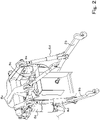
- illustrates a raising/lowering device.
- Fig. 3
- shows a side view of a combined implement.
- Fig. 4
- shows a plan view of the combined implement.
- Fig. 5
- illustrates automatic operation.
- Fig. 6A
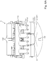
- illustrates first monitored information D1 and an obstacle D2.
- Fig. 6B
- shows an example of projections/depressions of an agricultural field (projections/depressions on the ground) D3a after work is done by a working device.
- Fig. 7
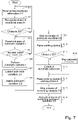
- shows how an automatic operation control unit and a work management unit operate.
- Fig. 8A
- illustrates a manner in which automatic operation is started with the working device held in a lowered position.
- Fig. 8B
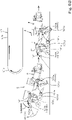
- illustrates a manner in which the working device is lowered from a raised position to the lowered position.
- Fig. 9
- illustrates a manner in which a second monitoring device is attached to the traveling vehicle body.
- Fig. 10
- is a general side view of a tractor.
- The following description discusses embodiments of the present invention with reference to drawings.
-
Fig. 10 illustrates atractor 1, which is an example of a working vehicle. The working vehicle is discussed using thetractor 1 as an example, but the working vehicle is not limited to a tractor and may be a rice transplanter or a combine. - As illustrated in
Fig. 10 , thetractor 1 includes: atraveling vehicle body 3 with atraveling device 7; aprime mover 4; and atransmission 5. Thetraveling device 7 includes front wheel(s) 7F and rear wheel(s) 7R. Thefront wheels 7F may be tire-shaped wheels and may be crawlershaped wheels. Therear wheels 7R also may be tire-shaped wheels and may be crawlershaped wheels. Theprime mover 4 is a diesel engine, an electric motor, and/or the like. Thetransmission 5 is capable of changing driving forces for the travelingdevice 7 by changing speed stages and switching the traveling state of the travelingdevice 7 between forward and rearward traveling states. Thetraveling vehicle body 3 is provided with acabin 9, and thecabin 9 is provided with the operator'sseat 10 therein. - Furthermore, the
traveling vehicle body 3 is provided with a linking device at the rear thereof. The linking device is a swinging drawbar which links a workingdevice 2 and thetraveling vehicle body 3 and does not raise or lower theworking device 2, a raising/loweringdevice 8 which is composed of a three-point linkage or the like and which raises and lowers theworking device 2, or the like. The linking device can have theworking device 2 attached thereto and detached therefrom. By linking the workingdevice 2 to the linking device, it is possible for the travelingvehicle body 3 to tow the workingdevice 2. The workingdevice 2 is a cultivator for cultivation, a fertilizer spreader for spreading fertilizer, a transplanter for planting seedlings, a water spreader for spreading water, an agricultural chemical spreader for spreading agricultural chemicals, a seed spreader for spreading seeds, a mower for mowing grass or the like, a tedder for tedding grass or the like, a rake for raking grass or the like, a baler for baling grass or the like, a combined implement for a plurality of types of work, and/or the like. -
Figs. 3 and4 illustrate a combined implement which is a type of the workingdevice 2. The combined implement as illustrated inFigs. 3 and4 includes a plurality of workingunits 101. The plurality of workingunits 101 include afirst working unit 101a, asecond working unit 101b, athird working unit 101c, afourth working unit 101d, afifth working unit 101e, and asixth working unit 101f. The workingunit 101a, thesecond working unit 101b, thethird working unit 101c, thefourth working unit 101d, thefifth working unit 101e, and the sixth workingunit 101f are arranged in this order from front to rear. Thefirst working unit 101a is located foremost, and the sixth workingunit 101f is located rearmost. - The
first working unit 101a is fertilizer applicator nozzle(s) to spread fertilizer introduced in container(s) 102 and is connected via hose(s) 103 to dispenser(s) 104 which dispenses the fertilizer from the container(s) 102. Thefirst working unit 101a spreads, onto an agricultural field (ground), fertilizer which has been dispensed into the hose(s) 103 by driving the dispenser(s) 104. Thesecond working unit 101b is tillage tine(s) to cultivate the agricultural field and is attached to arotation shaft 106 which is caused by adrive mechanism 105 to rotate. Thesecond working unit 101b is caused to rotate with the rotation of therotation shaft 106 to cultivate the agricultural field, by driving thedrive mechanism 105. Thethird working unit 101c is land leveler cover(s) disposed rearward of thesecond working unit 101b, and levels the cultivated ground. In the case of the combined implement inFigs. 3 and4 , thefirst working unit 101a, thesecond working unit 101b, and thethird working unit 101c are part of a fertilizer applicator. - The
fourth working unit 101d is grooving disc(s) for formation of grooves. Thefifth working unit 101e is seeding nozzle(s) to plant seeds introduced in container(s) 110 and is connected via hose(s) 111 to dispenser(s) 112 which dispenses the seeds from the container(s) 110. Thefifth working unit 101e plants, into groove(s) formed by thefourth working unit 101d, seeds which have been dispensed into the hose(s) 111 by driving the dispenser(s) 112. Thesixth working unit 101f is rotatably supported tamping roller(s) and tamps at least an area where seeds have been planted. In the case of the combined implement ofFigs. 3 and4 , thefourth working unit 101d, thefifth working unit 101e, and the sixth workingunit 101f are part of a seeder. - The
first working unit 101a, thesecond working unit 101b, thethird working unit 101c, thefourth working unit 101d, thefifth working unit 101e, and the sixth workingunit 101f are supported by aframe 115 and are configured to be raised and lowered by the raising/loweringdevice 8. Specifically, the fertilizer applicator and the seeder have theframe 115, and are supported onlift arms 8a,lower links 8b, atop link 8c,lift rods 8d, and liftcylinders 8e as illustrated inFig. 2 such that the fertilizer applicator and the seeder can be raised and lowered. - Furthermore, the dispenser(s) 104, the
drive mechanism 105, and the dispenser(s) 112 are driven (actuated) by rotation of a PTO shaft projecting from a rear portion of the travelingvehicle body 3. - As illustrated in
Fig. 2 , the raising/loweringdevice 8 includes liftarms 8a,lower links 8b, atop link 8c,lift rods 8d, and liftcylinders 8e. A front end of eachlift arm 8a is supported on an upper rear portion of a case (transmission case) housing thetransmission 5 such that thelift arm 8a is swingable up and down. Thelift arm 8a is driven by acorresponding lift cylinder 8e to swing (raised or lowered). Thelift cylinder 8e is composed of a hydraulic cylinder. Thelift cylinder 8e is connected to a hydraulic pump via acontrol valve 36. Thecontrol valve 36 is a solenoid valve or the like to cause thelift cylinder 8e to extend and retract. - A front end of each
lower link 8b is supported on a lower rear portion of thetransmission 5 such that thelower link 8b is swingable up and down. A front end of thetop link 8c is supported, at a position higher than thelower link 8b, on a rear portion of thetransmission 5 such that thetop link 8c is swingable up and down. Eachlift rod 8d connects acorresponding lift arm 8a and a correspondinglower link 8b. The workingdevice 2 is linked to rear portions of thelower links 8b and thetop link 8c. When thelift cylinders 8e are driven (extend or retract), thelift arms 8a ascend or descend, and thelower links 8b connected to thelift arms 8a via thelift rods 8d also ascend or descend. With this, the workingdevice 2 swings up or down (raised or lowered) about front portions of thelower links 8b. - As illustrated in
Fig. 1 , thetractor 1 includes asteering unit 29. Thesteering unit 29 includes asteering wheel 30, a rotation shaft (steering shaft) 31 which rotates as thesteering wheel 30 rotates, and an assist mechanism (power steering mechanism) 32 to assist steering performed using thesteering wheel 30. Theassist mechanism 32 includes ahydraulic pump 33, acontrol valve 34 supplied with hydraulic fluid discharged from thehydraulic pump 33, and asteering cylinder 35 which is actuated by thecontrol valve 34. Thecontrol valve 34 is a solenoid valve which is actuated according to a control signal. Thecontrol valve 34 is, for example, a threeway switching valve which achieves multi-position switching by movement of a spool or the like. The positions of thecontrol valve 34 can also be switched by steering by the steeringshaft 31. Thesteering cylinder 35 is connected to arms (knuckle arms) which change the orientation of thefront wheels 7F. - Therefore, upon operation of the
steering wheel 30, the position and the degree of opening of thecontrol valve 34 change according to thesteering wheel 30, and thesteering cylinder 35 extends or retracts leftward or rightward according to the position and the degree of opening of thecontrol valve 34, making it possible to change the steering direction of thefront wheels 7F. Note that the foregoingsteering unit 29 is an example, and the foregoing configuration does not imply limitation. - The
tractor 1 includes apositioning device 40. Thepositioning device 40 is capable of detecting the position thereof (measured position information including latitude and longitude) using a satellite positioning system (positioning satellites) such as D-GPS, GPS, GLONASS, BeiDou, Galileo, and/or Michibiki. Specifically, thepositioning device 40 receives satellite signals (positions of positioning satellites, time of transmission, correction information, and/or the like) from the positioning satellites, and detects the position (e.g., latitude and longitude) of thetractor 1, i.e., a vehicle body position, on the basis of the satellite signals. Thepositioning device 40 includes areceiver 41 and an inertial measurement unit (IMU) 42. Thereceiver 41 is a device which includes an antenna and/or the like and which receives satellite signals from the positioning satellites and is attached to the travelingvehicle body 3 separately from theinertial measurement unit 42. In the present embodiment, thereceiver 41 is attached to the travelingvehicle body 3, e.g., thecabin 9. Note that the location at which thereceiver 41 is attached is not limited to those described in embodiments. - The
inertial measurement unit 42 includes an acceleration sensor to detect acceleration, a gyroscope sensor to detect angular velocity, and/or the like. Theinertial measurement unit 42 is provided on the travelingvehicle body 3, for example, below the operator'sseat 10, and is capable of detecting the roll angle, pitch angle, yaw angle, and/or the like of the travelingvehicle body 3. - As illustrated in
Figs. 3 and4 , the workingdevice 2 is provided with first monitoring device(s) 121. Eachfirst monitoring device 121 is a device capable of detecting objects present in a surrounding area of the workingdevice 2. Thefirst monitoring device 121 is a camera (imaging device), a laser scanner, sonar, and/or the like. A camera (imaging device) captures an image of a surrounding area of the workingdevice 2 using an image sensor such as a CCD and/or CMOS, and thereby, when the captured image contains an object, detects the object. A laser scanner detects an object by emitting laser and receiving the reflected laser from the object. Sonar detects an object by emitting sound waves and receiving the reflected sound waves from the obstacle. - Each
first monitoring device 121 is attached, via abracket 117, to a distal end portion of asupport 116 which extends rearward from theframe 115 of the workingdevice 2. In the present embodiment,such supports 116 are provided on respective opposite sides (left and right sides) of theframe 115, and suchfirst monitoring devices 121 are attached to therespective supports 116 viarespective brackets 117. A viewing direction K1 of eachfirst monitoring device 121 is inclined downward relative to a horizontal direction to some degree, i.e., inclined toward working units. Note that the viewing direction is the direction of the optical axis of laser emitted in the case where thefirst monitoring device 121 is a laser scanner, is the direction of emission of sound waves in the case where thefirst monitoring device 121 is sonar and is the direction of the optical axis (central axis of a lens) of an image sensor in the case where thefirst monitoring device 121 is a camera. - An emitting
portion 121a to emit laser is located rearward of the sixth workingunit 101f which is located at the rearmost position of the workingdevice 2. In the case where thefirst monitoring device 121 is sonar, an emittingportion 121a to emit sound waves is located rearward of the sixth workingunit 101f. In the case where thefirst monitoring device 121 is a camera, a lens portion through which light passes is located rearward of the sixth workingunit 101f. - As illustrated in
Fig. 4 , a monitored area A1 of eachfirst monitoring device 121 is near and behind the workingdevice 2. Eachfirst monitoring device 121 is capable of performing monitoring by detecting what the object in the monitored area A1 is. The monitored areas A1 cover, for example, a continuous area extending between the left and right edges of the workingdevice 2. - As illustrated in
Fig. 1 , thetractor 1 includes acontrol device 60. Thecontrol device 60 is a device to perform control of a travel system of thetractor 1, control of a work system of thetractor 1, and/or the like. Thecontrol device 60 has anoperation changeover switch 65 connected thereto. Theoperation changeover switch 65 is capable of switching between ON and OFF. Thecontrol device 60 can be set to an automatic operation mode when theoperation changeover switch 65 is ON, and thecontrol device 60 can be set to a manual operation mode when theoperation changeover switch 65 is OFF. - The
control device 60 includes an automaticoperation control unit 63 which performs control relating to the automatic operation of the tractor 1 (traveling vehicle body 3) on the basis of a planned travel route. The automaticoperation control unit 63 is composed of electric/electronic circuit(s) provided in thecontrol device 60, program(s) stored in a CPU and/or the like, and/or the like. - The automatic
operation control unit 63 controls automatic operation of the travelingvehicle body 3. The automaticoperation control unit 63 starts the automatic operation when thetractor 1 is in an automatic operation mode. As illustrated inFig. 5 , when thetractor 1 is performing automatic operation, if the deviation between the vehicle body position and the planned travel route L1 is less than a threshold, the automaticoperation control unit 63 maintains the angle of rotation of the steering shaft (rotation shaft) 31. If the deviation between the vehicle body position and the planned travel route L1 is equal to or greater than the threshold and thetractor 1 is positioned leftward of the planned travel route L1, the automaticoperation control unit 63 causes the steeringshaft 31 to rotate so that thetractor 1 is steered right. If the deviation between the vehicle body position and the planned travel route L1 is equal to or greater than the threshold and thetractor 1 is positioned rightward of the planned travel route L1, the automaticoperation control unit 63 causes the steeringshaft 31 to rotate so that thetractor 1 is steered left. Note that, although the angle of steering by thesteering unit 29 is changed on the basis of the deviation between the vehicle body position and the planned travel route L1 in the above-described embodiment, the automaticoperation control unit 63 may, in the case where the direction of the planned travel route L1 and the travel direction of the tractor 1 (tractor body 3) (vehicle body heading direction) differ from each other, i.e., in the case where an angle of the vehicle body heading direction to the planned travel route L1 is equal to or greater than a threshold, set the angle of steering so that the angle is zero (the vehicle body heading direction F1 matches the direction of the planned travel route L1). The automaticoperation control unit 63 may set the final angle of steering for the automatic operation on the basis of an angle of steering determined based on the deviation (deviation in position) and an angle of steering determined based on directions (deviation in direction). Settings of the angle of steering in automatic operation in the above-described embodiment are examples, and do not imply any limitation. - Note that, in the case where the planned travel route L1 is associated with vehicle speed, the automatic
operation control unit 63 automatically changes the speed stage of the transmission, the speed of rotation of the prime mover, and/or the like so that the current speed of thetractor 1 matches the vehicle speed that corresponds to the planned travel route L1. - Furthermore, when the planned travel route L1 includes a straight route L1a and a turning route L1b, for example, the automatic
operation control unit 63 causes automatic operation to be performed along the straight route L1a while the workingdevice 2 is held in the lowered position so that the workingdevice 2 is in the working position, and, at and after the point in time at which the workingdevice 2 reaches the turning route L1b, causes automatic operation to be performed along the turning route L1b while the workingdevice 2 is held in the raised position so that the workingdevice 2 is in the non-working position. - The
control device 60 performs control relating to the automatic operation of the tractor 1 (traveling vehicle body 3) on the basis of not only the planned travel route L1 but also monitored information (first monitored information) obtained by thefirst monitoring device 121. As illustrated inFig. 6A , the automaticoperation control unit 63 determines the automatic operation to be performed if first monitored information D1 contains no obstacles D2 and determines the automatic operation not to be performed if the first monitored information D1 contains an obstacle D2. - The first monitored information D1 includes, for example, data of the profile (shape) of an object or the like obtained when laser is scanned over the monitored area A1 in the case where the
first monitoring device 121 is a laser scanner, includes the profile (shape) of an object or the like obtained when sound waves are scanned over the monitored area A1 in the case where thefirst monitoring device 121 is sonar, and includes data of an image (captured image) including the monitored area A1 in the case where thefirst monitoring device 121 is a camera. - The obstacle D2 is an animal such as a dog, a cat, or a raccoon dog, a human, or the like. Note that whether an object is an obstacle D2 or not is determined based on the size (height H1, width W1), actions, and/or the like of the object obtained using the first monitored information D1. For example, in the case where the object corresponds to the size of an animal such as a dog, a cat, a raccoon dog, or the like and moves as time passes, the object is determined to be an obstacle. How to determine whether the object is an obstacle D2 or not is not limited to the above example. Whether the object is an obstacle D2 or not may be determined based on the shape of the object or the temperature of the object, and there is no limitation.
- The automatic
operation control unit 63 refers to first monitored information D1 obtained by the first monitoring device(s) 121 when the tractor 1 (traveling vehicle body 3) is in a stopped state and in the automatic mode. If the first monitored information D1 contains an obstacle D2, the automaticoperation control unit 63 does not cause automatic operation to be started, that is, the automaticoperation control unit 63 keeps the tractor 1 (traveling vehicle body 3) in the stopped state. On the contrary, if the first monitored information D1 contains no obstacles D2, the automaticoperation control unit 63 causes the automatic operation to be started and causes the tractor 1 (traveling vehicle body 3) to travel along the planned travel route L1. - After the initiation of the automatic operation, the automatic
operation control unit 63 determines the automatic operation to be stopped if monitored information obtained when the workingdevice 2 is held in a raised position by the raising/loweringdevice 8 contains an obstacle D2 and determines the automatic operation to continue if the monitored information contains no obstacles D2. - The
control device 60 not only controls automatic travel on the basis of the first monitored information D1 obtained by thefirst monitoring devices 121 but also monitors worked condition(s) resulting from work done by the workingdevice 2. Thecontrol device 60 includes awork management unit 64. Thework management unit 64 is composed of electric/electronic circuit(s) provided in thecontrol device 60, program(s) stored in a CPU and/or the like, and/or the like. Thework management unit 64 extracts post-work conditions D3 (D3a, D3b) which are examples of the worked conditions, after the initiation of the automatic operation. As illustrated inFig. 6B , in the case where the workingdevice 2 is a seeder and/or a lister, elevations/depressions D3a in the agricultural field (elevations/depressions in the ground) and/or the like after the seeding are extracted. Specifically, upon initiation of the automatic operation, thework management unit 64 refers to the first monitored information D1 and analyzes the profiles (shapes) in the first monitored information D1 to thereby extract the elevations/depressions D3a in the agricultural field after work. Note thatFig. 6B is an example and does not imply any limitation. For example, in the case where the workingdevice 2 is a planter, post-work conditions D3 which are the conditions of the planted seedlings and/or the like can be extracted. Alternatively, post-work conditions D3 behind various types of workingdevice 2 can be detected. Upon extraction of post-work condition(s) D3, thework management unit 64 causes adisplay device 45 to display the extracted post-work condition(s) D3. Thedisplay device 45 is located, for example, in the vicinity of the operator'sseat 10, and an operator can check the post-work condition(s) D3 displayed on thedisplay device 45. -
Fig. 7 shows how the automaticoperation control unit 63 and thework management unit 64 operate. - The automatic
operation control unit 63 refers to the first monitored information D1 when the tractor 1 (traveling vehicle body 3) is in the stopped state and in the automatic mode (S1). The automaticoperation control unit 63 analyzes the first monitored information D1 to recognize an object in the monitored area A1 (S2). The automaticoperation control unit 63 determines whether or not the recognized object is an obstacle D2 (S3) and, if the object is an obstacle D2 (Yes in S3), the process returns to S1 and automatic operation is not started. - If the recognized object is not an obstacle D2 (No in S3), the automatic
operation control unit 63 permits the initiation of automatic operation (S4), and, when a start button to start the automatic operation is pressed (Yes in S5), causes the automatic operation to be performed (S6). The start button to start the automatic operation may be located in the vicinity of the operator'sseat 10 and may be located on an external terminal such as a smartphone, a tablet, a remote controller, and/or the like. In the case of an external terminal, once thecontrol device 60 has received, via a communication device on thetractor 1 from the external terminal, the fact indicating that the start button has been operated, the automaticoperation control unit 63 causes automatic operation to be performed. For example, as illustrated inFig. 8A , after the initiation of the automatic operation, the automaticoperation control unit 63 causes the workingdevice 2 to be lowered and causes thetractor 1 to travel (work against the ground) along a straight route L1a while performing the automatic operation. On the other hand, after the initiation of the automatic operation, when the work against the ground is being performed, thework management unit 64 analyzes the first monitored information D1 to recognize objects in the monitored area(s) A1 and extracts post-work condition(s) D3 such as elevations/depressions D3a, conditions D3b of planted seedlings, and/or the like in the agricultural field after the work (S7). Thework management unit 64 causes thedisplay device 45 to display the post-work condition(s) D3 (S8). - When the tractor 1 (traveling vehicle body 3) has reached a turning route L1b form the straight route L1a, the
work management unit 64 stops the process of extracting the post-work condition(s) D3 (S9), and the automaticoperation control unit 63 causes the raising/loweringdevice 8 to raise the working device 2 (S10). When the tractor 1 (traveling vehicle body 3) is traveling at least along the turning route L1b while performing the automatic operation with the workingdevice 2 in the raised position, the automaticoperation control unit 63 analyzes the first monitored information D1 to recognize an object in the monitored area A1 and determines whether or not the recognized object is an obstacle D2 (S11). If the recognized object is an obstacle D2 (Yes in S11), the automaticoperation control unit 63 determines the automatic operation to be stopped, i.e., determines the tractor 1 (traveling vehicle body 3) to be stopped (S12). - If the recognized object is not an obstacle D2 (No in S11), the automatic
operation control unit 63 determines the automatic operation to continue and causes the automatic operation to continue such that the tractor 1 (traveling vehicle body 3) moves along the turning route L1b with the workingdevice 2 in the raised position (S13). - As illustrated in
Fig. 8B , when the tractor 1 (traveling vehicle body 3) has reached a straight route L1a from the turning route L1b, the automaticoperation control unit 63 causes the raising/loweringdevice 8 to lower the workingdevice 2, thereby placing the workingdevice 2 in a working position (S14). After the workingdevice 2 is placed in the working position, the automaticoperation control unit 63 stops the process of extracting obstacle(s) D2 (S15), and thework management unit 64 resumes the process of extracting post-work condition(s) D3 (S16). - As has been discussed, the automatic
operation control unit 63 determines automatic operation to be performed if the first monitored information D1 contains no obstacles and determines the automatic operation not to be performed if the first monitored information D1 contains an obstacle D2. Furthermore, after the initiation of the automatic travel, the automaticoperation control unit 63 determines the automatic operation to be stopped if the first monitored information D1 obtained when the workingdevice 2 is held in the raised position by the raising/loweringdevice 8 contains an obstacle D2 and determines the automatic operation to continue if the first monitored information D1 contains no obstacles D2. Thework management unit 64 extracts worked condition(s) on the basis of the first monitored information D1 obtained in a period from the initiation of the automatic operation to the raising of the workingdevice 2 and does not extract the worked condition(s) while the workingdevice 2 is in the raised position. - In the above-described embodiment, with regard to the first monitored information D1 obtained by the
first monitoring devices 121, the control of the automatic operation by the automaticoperation control unit 63 and extraction (monitoring) of worked condition(s) resulting from the work done by the workingdevice 2 are performed automatically. Note, however, that these may be performed manually. As illustrated inFig. 1 , thetractor 1 includes aswitching device 66. The switchingdevice 66 is a switch capable of toggling between two positions, is located in the vicinity of the operator'sseat 10 and can be operated by an operator. When theswitching device 66 is in one of the two positions, monitoring (automatic operation monitoring) by the automaticoperation control unit 63 is performed using the first monitored information D1, and when theswitching device 66 is in the other of the two positions, monitoring (worked condition monitoring) by thework management unit 64 is performed using the first monitored information D1. - Note that the
tractor 1 may include second monitoring device(s) 122 as illustrated inFig. 9 . Thesecond monitoring device 122 is provided on the travelingvehicle body 3, and its viewing direction is the same as those of thefirst monitoring devices 121. As illustrated inFig. 9 , thesecond monitoring device 122 is attached to a rear portion of thecabin 9, more specifically, to an upper rear portion of thecabin 9, via bracket(s). The configuration of thesecond monitoring device 122 is the same as those of thefirst monitoring devices 121, and therefore is not repeated. A monitored area A2 of thesecond monitoring device 122 is located rearward of the travelingvehicle body 3 and includes an area between the travelingvehicle body 3 and the workingdevice 2. Monitored information obtained by thesecond monitoring device 122 can be used in automatic operation monitoring and worked condition monitoring, similar to thefirst monitoring devices 121. - A working vehicle (tractor 1) includes a traveling
vehicle body 3, a linkingdevice 8 capable of linking a workingdevice 2 to the travelingvehicle body 3, afirst monitoring device 121 to monitor at least a surrounding area of the workingdevice 2, thefirst monitoring device 121 being provided on the workingdevice 2, and acontrol device 60 to perform control relating to automatic operation of the travelingvehicle body 3 on the basis of a planned travel route L1 and monitored information (first monitored information) D1 obtained by thefirst monitoring device 121. With this, even in cases where the workingdevice 2 is linked to the travelingvehicle body 3, it is possible to monitor the surrounding area of the workingdevice 2 using thefirst monitoring device 121, and possible to perform automatic operation smoothly even in cases where the workingdevice 2 is linked to the travelingvehicle body 3. - The
control device 60 includes an automaticoperation control unit 63 to determine the automatic operation to be performed if the monitored information (first monitored information) D1 contains no obstacles and to determine the automatic operation not to be performed if the monitored information (first monitored information) D1 contains an obstacle. This achieves the following: the surrounding area of the workingdevice 2 is monitored using the monitored information (first monitored information) D1; and automatic operation is started if there are no obstacles D1 and the automatic operation is performed by the obstacle D1. This makes it possible to achieve more advanced automatic operation while the workingdevice 2 is attached to the travelingvehicle body 3. - The linking
device 8 is a raising/lowering device to raise and lower the workingdevice 2, and after initiation of the automatic operation, the automaticoperation control unit 63 determines the automatic operation to be stopped if the monitored information (first monitored information) D1 obtained when the workingdevice 2 is held in a raised position by the raising/lowering device contains an obstacle D2. With this, in the case where the workingdevice 2 is raised, it is possible to check the conditions of the surrounding area while the workingdevice 2 in the raised position, and possible to stop the automatic travel if there is an obstacle D2. - The
control device 60 includes awork management unit 64 to extract one or more worked conditions resulting from work done by the workingdevice 2 on the basis of the monitored information (first monitored information) D1 obtained by thefirst monitoring device 121. This makes it possible to know the worked conditions during work. - A working vehicle (tractor 1) includes a traveling
vehicle body 3, a linkingdevice 8 capable of linking a workingdevice 2 to the travelingvehicle body 3, afirst monitoring device 121 provided on the workingdevice 2, and acontrol device 60 including an automaticoperation control unit 63 to perform control relating to automatic operation of the travelingvehicle body 3 on the basis of a planned travel route L1 and monitored information (first monitored information) D1 obtained by thefirst monitoring device 121, and awork management unit 64 to extract one or more worked conditions resulting from work done by the workingdevice 2 on the basis of the monitored information (first monitored information) D1. This makes it possible to perform both the control of automatic travel and the monitoring of worked conditions using the first monitored information D1 obtained by thefirst monitoring device 121. - The
work management unit 64 extracts the one or more worked conditions after initiation of the automatic operation. This makes it possible to know, for example, worked conditions while work is done by automatic travel. - The linking
device 8 is a raising/lowering device to raise and lower the workingdevice 2, the automaticoperation control unit 63 determines the automatic operation to be performed if the monitored information (first monitored information) D1 contains no obstacles, and determines the automatic operation not to be performed if the monitored information (first monitored information) D1 contains an obstacle, and after initiation of the automatic travel, determines the automatic operation to be stopped if the monitored information (first monitored information) D1 obtained when the workingdevice 2 is held in a raised position by the raising/lowering device contains an obstacle, and determines the automatic operation to continue if the monitored information (first monitored information) D1 obtained when the workingdevice 2 is held in the raised position by the raising/lowering device contains no obstacles, and thework management unit 64 extracts the one or more worked conditions on the basis of the first monitored information (first monitored information) D1 obtained in a period from the initiation of the automatic operation to raising of the workingdevice 2. This not only achieves the following: automatic operation is started by the automaticoperation control unit 63 if there are no obstacles in the first monitored information D1 before the automatic operation; and the automatic operation is not performed by the automaticoperation control unit 63 if there is an obstacle, but also achieves the following: after the initiation of the automatic operation, it is possible to check worked conditions in a period from the initiation of the automatic operation to raising of the workingdevice 2, i.e., while work against the ground or the like is done by the workingdevice 2. - The working vehicle (tractor 1) further includes a switching device to, with regard to the monitored information (first monitored information) D1 obtained by the
first monitoring device 121, switch between control of the automatic operation by the automaticoperation control unit 63 and monitoring of the one or more worked conditions resulting from work done by the workingdevice 2. With this, an operator (driver) can easily switch between the monitoring in automatic operation and the monitoring of worked conditions, making it possible to perform appropriate monitoring according to work and/or the like. - The working vehicle (tractor 1) further includes a
second monitoring device 122 provided on the travelingvehicle body 3, a viewing direction of thesecond monitoring device 122 being the same as a viewing direction of thefirst monitoring device 121. With this, it is possible to perform monitoring relating to automatic operation or monitoring relating to work also using thesecond monitoring device 122, making it possible to assist thefirst monitoring device 121. For example, it is possible to monitor a space between the travelingvehicle body 3 and a front portion of the workingdevice 2 using thesecond monitoring device 122. - It is to be understood that the embodiments disclosed herein are considered as examples in all aspects and are not considered as limitations. The scope of the present invention is to be determined not by the foregoing description but by the claims and is intended to include all variations and modifications within the scope of the claims and their equivalents.
-
- 1
- Working vehicle (tractor)
- 2
- Working device
- 3
- Traveling vehicle body
- 8
- Raising/lowering device (linking device)
- 60
- Control device
- 63
- Automatic operation control unit
- 64
- Work management unit
- 66
- Switching device
- 121
- First monitoring device
- 122
- Second monitoring device
- D1
- Obstacle
- D2
- Obstacle
- L1
- Planned travel route
Claims (9)
- A working vehicle comprising:- a traveling vehicle body;- a linking device capable of linking a working device to the traveling vehicle body;- a first monitoring device to monitor at least a surrounding area of the working device, the first monitoring device being provided on the working device; and- a control device to perform control relating to automatic operation of the traveling vehicle body on the basis of a planned travel route and monitored information obtained by the first monitoring device.
- The working vehicle according to claim 1, wherein the control device includes an automatic operation control unit to determine the automatic operation to be performed if the monitored information contains no obstacles and to determine the automatic operation not to be performed if the monitored information contains an obstacle.
- The working vehicle according to claim 1 or 2, wherein:- the linking device is a raising/lowering device to raise and lower the working device; and- after initiation of the automatic operation, the automatic operation control unit determines the automatic operation to be stopped if the monitored information obtained when the working device is held in a raised position by the raising/lowering device contains an obstacle.
- The working vehicle according to any one of claims 1 to 3, wherein the control device includes a work management unit to extract one or more worked conditions resulting from work done by the working device on the basis of the monitored information obtained by the first monitoring device.
- A working vehicle comprising:- a traveling vehicle body;- a linking device capable of linking a working device to the traveling vehicle body;- a first monitoring device provided on the working device; and- a control device including- an automatic operation control unit to perform control relating to automatic operation of the traveling vehicle body on the basis of a planned travel route and monitored information obtained by the first monitoring device, and- a work management unit to extract one or more worked conditions resulting from work done by the working device on the basis of the monitored information.
- The working vehicle according to claim 5, wherein the work management unit extracts the one or more worked conditions after initiation of the automatic operation.
- The working vehicle according to claim 5 or 6, wherein:- the linking device is a raising/lowering device to raise and lower the working device;- the automatic operation control unit- determines the automatic operation to be performed if the monitored information contains no obstacles, and determines the automatic operation not to be performed if the monitored information contains an obstacle, and- after initiation of the automatic travel, determines the automatic operation to be stopped if the monitored information obtained when the working device is held in a raised position by the raising/lowering device contains an obstacle, and determines the automatic operation to continue if the monitored information obtained when the working device is held in the raised position by the raising/lowering device contains no obstacles; and- the work management unit extracts the one or more worked conditions on the basis of the first monitored information obtained in a period from the initiation of the automatic operation to raising of the working device.
- The working vehicle according to any one of claims 5 to 7, further comprising a switching device to, with regard to the monitored information obtained by the first monitoring device, switch between control of the automatic operation by the automatic operation control unit and monitoring of the one or more worked conditions resulting from work done by the working device.
- The working vehicle according to any one of claims 1 to 8, further comprising a second monitoring device provided on the traveling vehicle body, a viewing direction of the second monitoring device being the same as a viewing direction of the first monitoring device.
Applications Claiming Priority (2)
| Application Number | Priority Date | Filing Date | Title |
|---|---|---|---|
| JP2019239889A JP7301737B2 (en) | 2019-12-27 | 2019-12-27 | work vehicle |
| PCT/JP2020/048212 WO2021132355A1 (en) | 2019-12-27 | 2020-12-23 | Work vehicle |
Publications (2)
| Publication Number | Publication Date |
|---|---|
| EP4082315A1 true EP4082315A1 (en) | 2022-11-02 |
| EP4082315A4 EP4082315A4 (en) | 2024-01-10 |
Family
ID=76575258
Family Applications (1)
| Application Number | Title | Priority Date | Filing Date |
|---|---|---|---|
| EP20908317.9A Pending EP4082315A4 (en) | 2019-12-27 | 2020-12-23 | WORK VEHICLE |
Country Status (6)
| Country | Link |
|---|---|
| US (1) | US12290014B2 (en) |
| EP (1) | EP4082315A4 (en) |
| JP (1) | JP7301737B2 (en) |
| CN (1) | CN114746317B (en) |
| AU (1) | AU2020413943B2 (en) |
| WO (1) | WO2021132355A1 (en) |
Families Citing this family (2)
| Publication number | Priority date | Publication date | Assignee | Title |
|---|---|---|---|---|
| JP7066250B1 (en) | 2022-02-28 | 2022-05-13 | 株式会社ユニストロングジャパン | Agricultural work support system |
| JP7707131B2 (en) * | 2022-06-27 | 2025-07-14 | 株式会社クボタ | Working machine and capture system |
Citations (1)
| Publication number | Priority date | Publication date | Assignee | Title |
|---|---|---|---|---|
| JP2018116609A (en) | 2017-01-20 | 2018-07-26 | 株式会社クボタ | Work vehicle |
Family Cites Families (24)
| Publication number | Priority date | Publication date | Assignee | Title |
|---|---|---|---|---|
| JPS61141812A (en) * | 1984-12-14 | 1986-06-28 | 井関農機株式会社 | Reaping part protective apparatus in combine |
| JP4151137B2 (en) * | 1998-12-16 | 2008-09-17 | 株式会社豊田自動織機 | Obstacle detection device for vehicle and vehicle |
| US6882283B1 (en) * | 2002-05-29 | 2005-04-19 | At&T Corp. | Cable plow installation monitor method and apparatus |
| US9164955B2 (en) * | 2013-02-04 | 2015-10-20 | Ford Global Technologies | Trailer active back-up assist with object avoidance |
| ES2718580T3 (en) * | 2014-03-26 | 2019-07-02 | Yanmar Co Ltd | Autonomous Displacement Work Vehicle |
| US9841768B2 (en) * | 2014-03-28 | 2017-12-12 | Yanmar Co., Ltd. | Autonomous travelling service vehicle |
| WO2015147111A1 (en) * | 2014-03-28 | 2015-10-01 | ヤンマー株式会社 | Autonomously traveling work vehicle |
| US9282688B2 (en) * | 2014-04-25 | 2016-03-15 | Deere & Company | Residue monitoring and residue-based control |
| EP3175693B1 (en) * | 2014-07-30 | 2022-08-31 | Yanmar Power Technology Co., Ltd. | Remote control apparatus |
| EP3270253B1 (en) * | 2015-03-11 | 2022-09-07 | Kubota Corporation | Work vehicle and travel control device for automatic travel of work vehicle |
| JP6656047B2 (en) * | 2016-03-29 | 2020-03-04 | ヤンマー株式会社 | Combine |
| JP6772563B2 (en) * | 2016-06-03 | 2020-10-21 | 井関農機株式会社 | Tractor |
| JP6727971B2 (en) * | 2016-07-19 | 2020-07-22 | 株式会社クボタ | Work vehicle |
| WO2018135256A1 (en) | 2017-01-20 | 2018-07-26 | 株式会社クボタ | Work vehicle |
| US11582903B1 (en) * | 2017-05-17 | 2023-02-21 | Hydro-Gear Limited Partnership | Vision based guidance system and method for lawn mowing devices |
| CN107226087B (en) * | 2017-05-26 | 2019-03-26 | 西安电子科技大学 | A structured road automatic driving transport vehicle and its control method |
| JP6638702B2 (en) * | 2017-06-19 | 2020-01-29 | 井関農機株式会社 | Work vehicle and combine as this work vehicle |
| WO2019058752A1 (en) * | 2017-09-22 | 2019-03-28 | パナソニックIpマネジメント株式会社 | Livestock information management system, livestock barn, livestock information management program, and livestock information management method |
| JP6919531B2 (en) * | 2017-11-30 | 2021-08-18 | 井関農機株式会社 | Work vehicle |
| JP6881336B2 (en) * | 2018-01-30 | 2021-06-02 | 井関農機株式会社 | Work vehicle |
| JP2019146506A (en) * | 2018-02-26 | 2019-09-05 | 井関農機株式会社 | Automatic travel control device for combine |
| JP6916138B2 (en) * | 2018-03-28 | 2021-08-11 | ヤンマーパワーテクノロジー株式会社 | Automatic traveling device for work vehicles |
| JP6942666B2 (en) * | 2018-03-28 | 2021-09-29 | ヤンマーパワーテクノロジー株式会社 | Work vehicle |
| JP2024141812A (en) | 2023-03-29 | 2024-10-10 | 株式会社テクノプラスト | Swab removal device |
-
2019
- 2019-12-27 JP JP2019239889A patent/JP7301737B2/en active Active
-
2020
- 2020-12-23 CN CN202080084069.0A patent/CN114746317B/en active Active
- 2020-12-23 EP EP20908317.9A patent/EP4082315A4/en active Pending
- 2020-12-23 WO PCT/JP2020/048212 patent/WO2021132355A1/en not_active Ceased
- 2020-12-23 AU AU2020413943A patent/AU2020413943B2/en active Active
-
2022
- 2022-05-24 US US17/751,801 patent/US12290014B2/en active Active
Patent Citations (1)
| Publication number | Priority date | Publication date | Assignee | Title |
|---|---|---|---|---|
| JP2018116609A (en) | 2017-01-20 | 2018-07-26 | 株式会社クボタ | Work vehicle |
Also Published As
| Publication number | Publication date |
|---|---|
| AU2020413943B2 (en) | 2024-10-31 |
| AU2020413943A1 (en) | 2022-06-09 |
| US20220287216A1 (en) | 2022-09-15 |
| WO2021132355A1 (en) | 2021-07-01 |
| US12290014B2 (en) | 2025-05-06 |
| JP2021107200A (en) | 2021-07-29 |
| CN114746317B (en) | 2025-07-29 |
| CN114746317A (en) | 2022-07-12 |
| EP4082315A4 (en) | 2024-01-10 |
| JP7301737B2 (en) | 2023-07-03 |
Similar Documents
| Publication | Publication Date | Title |
|---|---|---|
| EP3634104B1 (en) | Improvements in or relating to tractor-baler combinations | |
| EP3634103B1 (en) | Improvements in or relating to vehicle-trailer combinations | |
| AU2021414757B2 (en) | Agriculture assistance system and unmanned aircraft | |
| EP3841860B1 (en) | Working vehicle, traveling management system for the working vehicle, and method for determining a status of a working vehicle | |
| AU2020413920B2 (en) | Work vehicle | |
| US12290014B2 (en) | Working vehicle | |
| EP4026415B1 (en) | Work vehicle and work assistance apparatus for work vehicle | |
| US12532795B2 (en) | Travel assistance system for agricultural machine | |
| US12127493B2 (en) | Working machine | |
| US20230165188A1 (en) | Method and appliance for lawn care with lane recognition | |
| JP7443209B2 (en) | Automatic driving support device | |
| US20260048798A1 (en) | Working vehicle | |
| EP4675386A1 (en) | Assist system for working machine and method of assisting working machine | |
| EP4677982A1 (en) | Evaluation system and evaluation method | |
| JP2025084174A (en) | Work vehicles | |
| WO2025142700A1 (en) | Work vehicle | |
| JP2026005057A (en) | Work vehicles | |
| NZ759247B2 (en) | Improvements in or relating to tractor-baler combinations | |
| KR20230149305A (en) | harvest |
Legal Events
| Date | Code | Title | Description |
|---|---|---|---|
| STAA | Information on the status of an ep patent application or granted ep patent |
Free format text: STATUS: THE INTERNATIONAL PUBLICATION HAS BEEN MADE |
|
| PUAI | Public reference made under article 153(3) epc to a published international application that has entered the european phase |
Free format text: ORIGINAL CODE: 0009012 |
|
| STAA | Information on the status of an ep patent application or granted ep patent |
Free format text: STATUS: REQUEST FOR EXAMINATION WAS MADE |
|
| 17P | Request for examination filed |
Effective date: 20220524 |
|
| AK | Designated contracting states |
Kind code of ref document: A1 Designated state(s): AL AT BE BG CH CY CZ DE DK EE ES FI FR GB GR HR HU IE IS IT LI LT LU LV MC MK MT NL NO PL PT RO RS SE SI SK SM TR |
|
| DAV | Request for validation of the european patent (deleted) | ||
| DAX | Request for extension of the european patent (deleted) | ||
| A4 | Supplementary search report drawn up and despatched |
Effective date: 20231211 |
|
| RIC1 | Information provided on ipc code assigned before grant |
Ipc: A01B 69/04 20060101ALI20231205BHEP Ipc: B60W 60/00 20200101ALI20231205BHEP Ipc: B60W 30/08 20120101ALI20231205BHEP Ipc: B60W 40/02 20060101ALI20231205BHEP Ipc: B62D 49/00 20060101ALI20231205BHEP Ipc: A01B 69/00 20060101AFI20231205BHEP |
|
| GRAP | Despatch of communication of intention to grant a patent |
Free format text: ORIGINAL CODE: EPIDOSNIGR1 |
|
| STAA | Information on the status of an ep patent application or granted ep patent |
Free format text: STATUS: GRANT OF PATENT IS INTENDED |
|
| INTG | Intention to grant announced |
Effective date: 20260217 |