EP4082314A1 - Lifting assembly for an agricultural vehicle - Google Patents
Lifting assembly for an agricultural vehicle Download PDFInfo
- Publication number
- EP4082314A1 EP4082314A1 EP22170828.2A EP22170828A EP4082314A1 EP 4082314 A1 EP4082314 A1 EP 4082314A1 EP 22170828 A EP22170828 A EP 22170828A EP 4082314 A1 EP4082314 A1 EP 4082314A1
- Authority
- EP
- European Patent Office
- Prior art keywords
- connection
- lifting system
- body portion
- lateral
- respect
- Prior art date
- Legal status (The legal status is an assumption and is not a legal conclusion. Google has not performed a legal analysis and makes no representation as to the accuracy of the status listed.)
- Granted
Links
Images

Classifications
-
- A—HUMAN NECESSITIES
- A01—AGRICULTURE; FORESTRY; ANIMAL HUSBANDRY; HUNTING; TRAPPING; FISHING
- A01B—SOIL WORKING IN AGRICULTURE OR FORESTRY; PARTS, DETAILS, OR ACCESSORIES OF AGRICULTURAL MACHINES OR IMPLEMENTS, IN GENERAL
- A01B59/00—Devices specially adapted for connection between animals or tractors and agricultural machines or implements
- A01B59/06—Devices specially adapted for connection between animals or tractors and agricultural machines or implements for machines mounted on tractors
- A01B59/066—Devices specially adapted for connection between animals or tractors and agricultural machines or implements for machines mounted on tractors of the type comprising at least two lower arms and one upper arm generally arranged in a triangle, e.g. three-point hitches
-
- A—HUMAN NECESSITIES
- A01—AGRICULTURE; FORESTRY; ANIMAL HUSBANDRY; HUNTING; TRAPPING; FISHING
- A01B—SOIL WORKING IN AGRICULTURE OR FORESTRY; PARTS, DETAILS, OR ACCESSORIES OF AGRICULTURAL MACHINES OR IMPLEMENTS, IN GENERAL
- A01B59/00—Devices specially adapted for connection between animals or tractors and agricultural machines or implements
- A01B59/04—Devices specially adapted for connection between animals or tractors and agricultural machines or implements for machines pulled or pushed by a tractor
- A01B59/041—Devices specially adapted for connection between animals or tractors and agricultural machines or implements for machines pulled or pushed by a tractor preventing or limiting side-play of implements
- A01B59/0415—Devices specially adapted for connection between animals or tractors and agricultural machines or implements for machines pulled or pushed by a tractor preventing or limiting side-play of implements by hydraulic or pneumatic means acting on the lower draft links
Definitions
- the present invention concerns a lifting assembly, in particular a lifting assembly for an agricultural vehicle.
- the present invention finds its preferred, although not exclusive, application in rear lifting system for a tractor.
- Agricultural vehicle such as tractors usually comprises lifting systems configured to allow the connection of the tractor to a trailer or to implements to provide different work operations.
- known prior art lifting system 1' usually comprises a pair of arms 2' carried by a lifting cylinder 3' that is interposed between tractor's body 4' and a rocker element 5'.
- the rocker element 5' extends transversally over the tractor's body 4' to joint together the two arms 2' to compensate torque acting between these latter.
- the two arms are furthermore connected to the rocker element 5' via guide rods 6'.
- An aim of the present invention is to satisfy the above mentioned needs in an optimized and cost effective way.
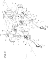
- Figure 2 discloses a lifting system 1 for an agricultural vehicle, e.g. a tractor.
- the lifting system 1 comprises a right portion 1' and a left portion 1" with respect to a longitudinal axis A of the vehicle.
- the vehicle is shown only in a portion 2 of the vehicle's body and comprising a portion of axle support 3, namely a right and a left axle supports, that both extends transversally with respect to longitudinal axis A and concentric one with respect to the other.
- the lifting system 1 comprises a pair of lateral connecting arms 4, one for each between right portion 1' and left portion 1", and a central connecting arm 5.
- Both the lateral connecting arms 4 and the central connecting arm 5 defines a terminal connection portion 4a, 5a suitable for being connected to an element to be coupled with the agricultural vehicle.
- terminal connection portions 4a, 5a are placed on opposite side on the respective arm with respect to tractor's body 4 and are, exemplarily, shaped as a hook.
- the terminal coupling portions 5b of the central arm 5, opposite to the terminal connection portion 5a is carried by portion 2 via a movable connection 6 such as a hinge.
- the central arm 5 is provided with adjusting means 7, e.g. a hydraulic top link, configured to vary the length between terminal portions 5a, 5b.
- the lateral arms 4 are each connected to the body portion 2, as described in the following, via a terminal coupling portion 4b opposite to the terminal connection portion 4a.
- the central portion 4c of each arm 4 is made of a rigid element, such as a metal bar, having a predefined cross-section; in the disclosed embodiment each arm is represented by a metal bar having a rectangular cross-section.
- the lateral arms 4 are each further connected to the portion 2 via actuator means 8 comprising a lower extremity 8a connected to the central portion 4c of the lateral arm 4 and an upper extremity 8b connected to the body portion 2 as described in the following.
- the lower extremity 8b is coupled to the central portion 4c via a hinge 9 configured to allow the rotation of central portion 4c about an axis transversal to axis A, preferably perpendicular to this latter.
- the lateral arms 4 are each further connected to the portion 2 via stabilizer means 11 comprising an outer extremity 11a connected to the central portion 4c of the lateral arm 4 and an inner extremity 11b connected to the body portion 2.
- stabilizer means 11 comprising an outer extremity 11a connected to the central portion 4c of the lateral arm 4 and an inner extremity 11b connected to the body portion 2.
- both the inner and outer extremities 11a, 11b are connected to the respective element via movable connections such as a hinge connection 12.
- stabilizer means 11 are connected to central portion 4c between the connection of lower extremity 8a with this latter and the terminal connection portion 4a.
- stabilizer means 11 may be realized as hydraulic dampers placed in a lower portion of the body 2 and inclined with respect to axis A or via equivalent mechanical links. Furthermore, they may be disposed differently with respect to the shown disposition.
- the coupling terminal portions 4b of each arm 4 and the upper extremity 8b of each actuator 8 may be connected to a support structure 13 that can be selectively fixed to the body portion 2.
- support structure 13 comprises a ring 14 that may be housed about axle support 3 via a selective fixing connection such as a threaded connection. Accordingly, a plurality of threaded elements 15 may be used for fixing the support structure 13 to the body 2 about the axle support 3.
- the upper portion 8b of actuator 8 is connected to support structure 13 via an upper cantilevered portion 16.
- the upper cantilevered portion 16 is advantageously fixedly carried by support structure 13 and preferably realized as one piece with the latter.
- the upper portion 8b is carried by upper cantilevered portion 16 in a movable manner, e.g. via a hinge connection 17.
- the hinge connection 17 is advantageously realized to allow the rotation of actuator about two axis that are transversal with respect to axis A.
- the coupling terminal portion 4b of lateral arm 4 is connected to support structure 3 via a lower cantilevered portion 18.
- the lower cantilevered portion 18 is advantageously fixedly carried by support structure 13 and preferably realized as one piece with the latter.
- the upper portion 8b is carried by lower cantilevered portion 16 in a movable manner, e.g. via a hinge connection 19.
- the hinge connection 19 is advantageously realized as a spherical joint.
- the actuator 8 and the stabilizer means 11 are, as said, hydraulic cylinders that are controlled by a hydraulic circuit that may be design of any typology according to the necessity of the vehicle.
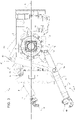
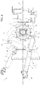
- actuators 8 are controlled to extend or retract (see figures 3 and 4 ) to low or rise the respective lateral arm 4, i.e. to vary their inclination with respect to longitudinal axis A in a vertical plane.
- stabilizer means 11 are adjusted, manually or automatically, to extend or retract to space out or near together between themselves the lateral arm 4, i.e. to vary their inclination with respect to longitudinal axis A in a horizontal plane.
- actuators 8 The control of extension or retraction of actuators 8 is achieved via a central control unit (not shown) that receives input on the necessary position of lateral arms 4 and that varies accordingly the actuation of actuators 8.
- the lifting assembly 1 is furthermore provided with sensor means (not shown) configured to detect operational parameters related to the torque acting on lateral arms 4 with respect to body 2.
- such sensor means may comprise torque means, e.g. placed in hinge 19 and configured to detect an inward or outward torque acting on lateral arm 3 and/or position means, e.g. angular position means, configured to detect the position of the terminal connection portion 4a of the lateral arm 4.
- torque means e.g. placed in hinge 19 and configured to detect an inward or outward torque acting on lateral arm 3 and/or position means, e.g. angular position means, configured to detect the position of the terminal connection portion 4a of the lateral arm 4.
- the control unit is configured to be electronically connected, e.g. via cables or wireless, to the aforementioned sensor means and to acquire the data detected by this latter to control the operation of actuator means 8.
- the tractor may be provided with signaling means (not shown) configured to signal a condition of danger when said detected value is higher with respect to the threshold value.
- the signaling means may comprise visual and/or sonic means configured to emit light or sounds to warn the driver if a dangerous condition is reached.
- the unit may control the lifting or lowering of the lateral arms via actuator means 8.
- the hydraulic circuit will impart an oil flow configured to retract or extend the hydraulic cylinder thereby lowering or lifting the lateral arm 4.
- the terminal connection portion 4a will move about a circumference having a radius equal to the length along axis A of lateral arm 4 and centered on hinge 4b.
- the lateral arm 4 may be lifted or lowered to allow the connection with a specific implement to be trailed by the tractor.
- the sensor means may continuously, alternatively at preset interval time, detect the torque and/or angular position of the lateral arms 4.
- Such detected value is acquired by the control unit and compared with a threshold torque and/or angular position of lateral arms 4 that is considered as maximum allowed torque and/or angular position for a safe operation of lateral arm 4, i.e. to avoid undesired failures.
- a threshold torque and/or angular position of lateral arms 4 that is considered as maximum allowed torque and/or angular position for a safe operation of lateral arm 4, i.e. to avoid undesired failures.
- Such threshold value may be memorized in the control unit and derived from experimental values that are specific with respect to the geometry of the lifting system 1.
- control unit may control actuator means 8 and/or stabilizer means 11 to vary the position of the lateral arms 4 thereby reducing the torque acting on these latter.
- the corrective actions may comprise a variation of position of the lateral arms 4.
- the method may further comprise a signalization step wherein, if such detected value is higher with respect to such memorized value, signaling means are activated to warn the driver.
- the proposed system is lighter and comprises less elements with respect to known systems.
- guide rods and rockers that are usually used in known lifting systems are avoided.
- this latter can be equipped of the lifting assembly only when needed.
- left and right lifting portions are therefore independent one with respect to the other.
- the provided systems allows to avoid undesired failures in the lifting assembly due to the continuous monitoring of values related to the torque acting between lateral arms 4 and body portion 2. Indeed, such torque is supported by rockers in known system, that are absent in the present lifting assembly.
- the shape of the elements comprised by the lifting assembly 1 may be varied according to the vehicle necessities.
- the signaling means may be present or absent, such as stabilizer means 11 that may be substituted by equivalent mechanical or hydraulic structures.
Landscapes
- Life Sciences & Earth Sciences (AREA)
- Zoology (AREA)
- Engineering & Computer Science (AREA)
- Mechanical Engineering (AREA)
- Soil Sciences (AREA)
- Environmental Sciences (AREA)
- Lifting Devices For Agricultural Implements (AREA)
- Transplanting Machines (AREA)
Abstract
- a pair of lateral arms (4) defining a connection portion (4a), actuator means (8) for actuating each of said pair of lateral arms (4) and comprising a lower portion (8a) connected between connection and coupling portions (4a, 4b) of lateral arms (4) and an upper portion (8b) connected to said body portion (2);
wherein the lower portion (8a) and the upper portion (8b) are connected to the respective element via movable connections (9, 17), the actuator means (8) being configured to increase or decrease their dimension to lift or lower said connection portion (4a) with respect to ground,
wherein the upper portion (8b) and the coupling portion (4b) are both connected to a same support element (13) that is carried by body portion (2).
Description
- The present invention concerns a lifting assembly, in particular a lifting assembly for an agricultural vehicle.
- The present invention finds its preferred, although not exclusive, application in rear lifting system for a tractor.
- Agricultural vehicle such as tractors usually comprises lifting systems configured to allow the connection of the tractor to a trailer or to implements to provide different work operations.
- In particular, making reference to
figure 1 , known prior art lifting system 1' usually comprises a pair of arms 2' carried by a lifting cylinder 3' that is interposed between tractor's body 4' and a rocker element 5'. The rocker element 5' extends transversally over the tractor's body 4' to joint together the two arms 2' to compensate torque acting between these latter. The two arms are furthermore connected to the rocker element 5' via guide rods 6'. - It is evident that the above defined configuration leads to encumbrance problems, namely:
- The presence of guide rods 6' limits the useful space above the arms 2';
- The presence of rockers 5' limits the useful space above tractor's body 4'.
- Moreover, it is clear that the presence of guide rods 6' and rockers 5' increases the weight of the lifting system 1', its complexity and its manufacturing costs.
- Therefore, the need is felt to provide a lifting system that has reduced encumbrances while maintaining the same functionalities.
- An aim of the present invention is to satisfy the above mentioned needs in an optimized and cost effective way.
- The aforementioned aim is reached by a lifting system and a vehicle as claimed in the appended set of claims.
- For a better understanding of the present invention, a preferred embodiment is described in the following, by way of a non-limiting example, with reference to the attached drawings wherein:
-
Figure 1 is a schematized lateral view of a lifting system as known in prior art; -
Figure 2 is a schematic perspective view of the lifting system according to the invention; -
Figure 3 is a schematic lateral view of the lifting system offigure 2 in a first operational condition; and -
Figure 4 is a schematic lateral view of the lifting system offigure 2 in a second operational condition. -
Figure 2 discloses alifting system 1 for an agricultural vehicle, e.g. a tractor. Thelifting system 1 comprises a right portion 1' and aleft portion 1" with respect to a longitudinal axis A of the vehicle. - The vehicle is shown only in a
portion 2 of the vehicle's body and comprising a portion ofaxle support 3, namely a right and a left axle supports, that both extends transversally with respect to longitudinal axis A and concentric one with respect to the other. - The
lifting system 1 comprises a pair of lateral connecting arms 4, one for each between right portion 1' andleft portion 1", and a central connectingarm 5. - Both the lateral connecting arms 4 and the central connecting
arm 5 defines aterminal connection portion - Accordingly, the
terminal connection portions - The
terminal coupling portions 5b of thecentral arm 5, opposite to theterminal connection portion 5a is carried byportion 2 via amovable connection 6 such as a hinge. Thecentral arm 5 is provided with adjusting means 7, e.g. a hydraulic top link, configured to vary the length betweenterminal portions body portion 2, as described in the following, via aterminal coupling portion 4b opposite to theterminal connection portion 4a. Advantageously, thecentral portion 4c of each arm 4 is made of a rigid element, such as a metal bar, having a predefined cross-section; in the disclosed embodiment each arm is represented by a metal bar having a rectangular cross-section. - The lateral arms 4 are each further connected to the
portion 2 via actuator means 8 comprising alower extremity 8a connected to thecentral portion 4c of the lateral arm 4 and anupper extremity 8b connected to thebody portion 2 as described in the following. - In particular, the
lower extremity 8b is coupled to thecentral portion 4c via ahinge 9 configured to allow the rotation ofcentral portion 4c about an axis transversal to axis A, preferably perpendicular to this latter. - The lateral arms 4 are each further connected to the
portion 2 via stabilizer means 11 comprising anouter extremity 11a connected to thecentral portion 4c of the lateral arm 4 and aninner extremity 11b connected to thebody portion 2. In particular, both the inner andouter extremities hinge connection 12. - Preferably, stabilizer means 11 are connected to
central portion 4c between the connection oflower extremity 8a with this latter and theterminal connection portion 4a. - Clearly, stabilizer means 11 may be realized as hydraulic dampers placed in a lower portion of the
body 2 and inclined with respect to axis A or via equivalent mechanical links. Furthermore, they may be disposed differently with respect to the shown disposition. - Advantageously, the coupling
terminal portions 4b of each arm 4 and theupper extremity 8b of eachactuator 8 may be connected to asupport structure 13 that can be selectively fixed to thebody portion 2. - In particular,
support structure 13 comprises aring 14 that may be housed aboutaxle support 3 via a selective fixing connection such as a threaded connection. Accordingly, a plurality of threadedelements 15 may be used for fixing thesupport structure 13 to thebody 2 about theaxle support 3. - The
upper portion 8b ofactuator 8 is connected to supportstructure 13 via an upper cantileveredportion 16. The upper cantileveredportion 16 is advantageously fixedly carried bysupport structure 13 and preferably realized as one piece with the latter. Theupper portion 8b is carried by upper cantileveredportion 16 in a movable manner, e.g. via ahinge connection 17. Thehinge connection 17 is advantageously realized to allow the rotation of actuator about two axis that are transversal with respect to axis A. - The
coupling terminal portion 4b of lateral arm 4 is connected to supportstructure 3 via a lower cantileveredportion 18. The lower cantileveredportion 18 is advantageously fixedly carried bysupport structure 13 and preferably realized as one piece with the latter. Theupper portion 8b is carried by lower cantileveredportion 16 in a movable manner, e.g. via ahinge connection 19. Thehinge connection 19 is advantageously realized as a spherical joint. - As shown the upper and lower cantilevered
portions support structure 13 withrespect axle support 3. - The
actuator 8 and the stabilizer means 11 are, as said, hydraulic cylinders that are controlled by a hydraulic circuit that may be design of any typology according to the necessity of the vehicle. - In particular,
actuators 8 are controlled to extend or retract (seefigures 3 and4 ) to low or rise the respective lateral arm 4, i.e. to vary their inclination with respect to longitudinal axis A in a vertical plane. - Similarly, stabilizer means 11 are adjusted, manually or automatically, to extend or retract to space out or near together between themselves the lateral arm 4, i.e. to vary their inclination with respect to longitudinal axis A in a horizontal plane.
- The control of extension or retraction of
actuators 8 is achieved via a central control unit (not shown) that receives input on the necessary position of lateral arms 4 and that varies accordingly the actuation ofactuators 8. - The
lifting assembly 1 is furthermore provided with sensor means (not shown) configured to detect operational parameters related to the torque acting on lateral arms 4 with respect tobody 2. - Advantageously, such sensor means may comprise torque means, e.g. placed in
hinge 19 and configured to detect an inward or outward torque acting onlateral arm 3 and/or position means, e.g. angular position means, configured to detect the position of theterminal connection portion 4a of the lateral arm 4. - The control unit is configured to be electronically connected, e.g. via cables or wireless, to the aforementioned sensor means and to acquire the data detected by this latter to control the operation of actuator means 8.
- Advantageously, the tractor may be provided with signaling means (not shown) configured to signal a condition of danger when said detected value is higher with respect to the threshold value.
- In such case, the signaling means may comprise visual and/or sonic means configured to emit light or sounds to warn the driver if a dangerous condition is reached.
- The operation of the above described
lifting assembly 1 according to the invention is the following. - The unit may control the lifting or lowering of the lateral arms via actuator means 8. Indeed, the hydraulic circuit will impart an oil flow configured to retract or extend the hydraulic cylinder thereby lowering or lifting the lateral arm 4. Accordingly, the
terminal connection portion 4a will move about a circumference having a radius equal to the length along axis A of lateral arm 4 and centered onhinge 4b. - Therefore, the lateral arm 4 may be lifted or lowered to allow the connection with a specific implement to be trailed by the tractor.
- In particular, when the lateral arms 4 are connected to the respective implement that is trailed by the tractor, the sensor means may continuously, alternatively at preset interval time, detect the torque and/or angular position of the lateral arms 4.
- Such detected value is acquired by the control unit and compared with a threshold torque and/or angular position of lateral arms 4 that is considered as maximum allowed torque and/or angular position for a safe operation of lateral arm 4, i.e. to avoid undesired failures. Such threshold value may be memorized in the control unit and derived from experimental values that are specific with respect to the geometry of the
lifting system 1. - If such detected value is lower with respect to such threshold value, no action is carried out.
- If such detected value is higher with respect to such threshold value, the control unit provides corrective actions. In particular, control unit may control actuator means 8 and/or stabilizer means 11 to vary the position of the lateral arms 4 thereby reducing the torque acting on these latter.
- Thanks to the above defined lift assembly, it is possible to provide a method for limiting the torque acting between the lateral arms 4 and the tractors'
body 2 comprising the followings steps: - Detecting a value representing a torque acting between the lateral arms 4 and the tractor's
body 2; - Comparing such detected value with a memorized value;
- If such detected value is lower with respect to such memorized value, no actions are carried out;
- If such detected value is higher with respect to such memorized value, corrective actions are carried out.
- In particular, the corrective actions may comprise a variation of position of the lateral arms 4.
- Furthermore, the method may further comprise a signalization step wherein, if such detected value is higher with respect to such memorized value, signaling means are activated to warn the driver.
- In view of the foregoing, the advantages of a
lifting system 1 according to the invention are apparent. - The proposed system is lighter and comprises less elements with respect to known systems. In particular, guide rods and rockers that are usually used in known lifting systems are avoided.
- Accordingly, the proposed system is more compact and economic.
- Moreover, thanks to support
structure 13 that can be selectively fixed to thebody portion 2 of the tractor, this latter can be equipped of the lifting assembly only when needed. - Moreover, it is possible to use the
same lifting assembly 1 on different tractors' body simply coupling thesupport structure 13 to the body portion on the latter, provided that a specific coupling portion is provided. In this way, there is a clear economic advantage for scale economy in production of the liftingassembly 1. - Moreover, it is clear that left and right lifting portions are therefore independent one with respect to the other.
- Furthermore, the provided systems allows to avoid undesired failures in the lifting assembly due to the continuous monitoring of values related to the torque acting between lateral arms 4 and
body portion 2. Indeed, such torque is supported by rockers in known system, that are absent in the present lifting assembly. - It is clear that modifications can be made to the described
lifting system 1 which do not extend beyond the scope of protection defined by the claims. - For example, the shape of the elements comprised by the lifting
assembly 1 may be varied according to the vehicle necessities. - Moreover, the signaling means may be present or absent, such as stabilizer means 11 that may be substituted by equivalent mechanical or hydraulic structures.
Claims (13)
- - Lifting system (1) for a work vehicle, said lifting system (1) comprising:- a pair of lateral arms (4) defining a connection portion (4a) configured for allowing the connection of the lateral arm (4) to an element carried by the work vehicle and a coupling portion (4b) opposite to the connection portion (4a) and configured to allow a movable connection of the lateral arm (4) with respect to a body portion the work vehicle,- actuator means (8) for actuating each of said pair of lateral arms (4) and comprising a lower portion (8a) connected between the connection and coupling portions (4a, 4b) and an upper portion (8b) connected to said body portion (2);wherein said lower portion (8a) and said upper portion (8b) are connected to the respective element via movable connections (9, 17), said actuator means (8) being configured to increase or decrease their dimension to lift or lower said connection portion (4a) with respect to ground,wherein said upper portion (8b) and said coupling portion (4b) are both connected to a same support element (13) that is carried by body portion (2).
- - Lifting system according to claim 1, wherein said support element (13) is selectively carried by said body portion (2).
- - Lifting system according to claim 1 or 2, wherein said support element (13) is fixed to said body portion (2) via threaded means.
- - Lifting system according to any of claims 1 to 3, wherein said support element (13) has an annular shape configured to surround an axle support (3) carried by said body portion (2) and comprises an upper portion (16) configured to allow the connection with said actuator means (8) and a lower portion (18) configured to allow the connection with said lateral arm (4), said upper portion (16) and lower portion (17) being placed on opposite vertical sided with respect to said axle support (3).
- - Lifting system according to any of said preceding claims, wherein said movable connections (9, 17) comprises a hinge connection.
- - Lifting system according to any of said preceding claims, wherein at least one between said movable connections (9, 17) comprises a two degrees of freedom connection.
- - Lifting system according to claim 4 to 6, wherein said lower portion (18) is connected to said lateral arm (4) via a hinge connection (19).
- - Lifting system according to any of said preceding claims, wherein said actuator means (8) comprise a hydraulic cylinder.
- - Lifting system according to any of said preceding claims, wherein said lifting system (1) comprises a central arm (5) that is laterally comprised between said lateral arms (4), said central arm (5) comprising a connection portion (5a) configured for allowing the connection of the latter to an element carried by the work vehicle and a coupling portion (5b) opposite to the connection portion (5a) and configured to allow a movable connection of the central arm (5) with respect to said body portion (2).
- Lifting assembly according to any of the preceding claims, wherein said lateral arms (4) are further connected to said body portion (2) via stabilizer means (11) comprising an outer extremity (11a) connected to said lateral arm (4) and an inner extremity (11b) connected to said body portion (2).
- - Lifting assembly according to claim 10, wherein said stabilizer means (11) are hydraulic Cylinders.
- - Lifting assembly according to any of the preceding claims, wherein said lateral arms (4) are each connected by a respective support structure (13), one independent with respect to the other.
- Work vehicle comprising a lifting assembly (1) according to any of the preceding claims.
Applications Claiming Priority (1)
| Application Number | Priority Date | Filing Date | Title |
|---|---|---|---|
| IT102021000010838A IT202100010838A1 (en) | 2021-04-29 | 2021-04-29 | LIFTING SYSTEM FOR AGRICULTURAL VEHICLES |
Publications (2)
| Publication Number | Publication Date |
|---|---|
| EP4082314A1 true EP4082314A1 (en) | 2022-11-02 |
| EP4082314B1 EP4082314B1 (en) | 2025-06-04 |
Family
ID=76708349
Family Applications (1)
| Application Number | Title | Priority Date | Filing Date |
|---|---|---|---|
| EP22170828.2A Active EP4082314B1 (en) | 2021-04-29 | 2022-04-29 | Lifting assembly for a work vehicle |
Country Status (2)
| Country | Link |
|---|---|
| EP (1) | EP4082314B1 (en) |
| IT (1) | IT202100010838A1 (en) |
Citations (2)
| Publication number | Priority date | Publication date | Assignee | Title |
|---|---|---|---|---|
| US3098528A (en) * | 1960-12-16 | 1963-07-23 | Ford Motor Co | Tractor hitches |
| EP1575350A1 (en) * | 2002-12-19 | 2005-09-21 | Agco SA | Automated hitching system |
-
2021
- 2021-04-29 IT IT102021000010838A patent/IT202100010838A1/en unknown
-
2022
- 2022-04-29 EP EP22170828.2A patent/EP4082314B1/en active Active
Patent Citations (2)
| Publication number | Priority date | Publication date | Assignee | Title |
|---|---|---|---|---|
| US3098528A (en) * | 1960-12-16 | 1963-07-23 | Ford Motor Co | Tractor hitches |
| EP1575350A1 (en) * | 2002-12-19 | 2005-09-21 | Agco SA | Automated hitching system |
Also Published As
| Publication number | Publication date |
|---|---|
| IT202100010838A1 (en) | 2022-10-29 |
| EP4082314B1 (en) | 2025-06-04 |
Similar Documents
| Publication | Publication Date | Title |
|---|---|---|
| US8201849B2 (en) | Agricultural vehicle balancing system | |
| US12543617B2 (en) | Implement weight transfer monitoring and wing control | |
| CN111887028B (en) | Combined arm guide wheel height control for crop harvesting apparatus | |
| US9357691B2 (en) | Hydraulic arrangement for a lifting unit | |
| EP3155886A1 (en) | Hitch system | |
| EP2544985B1 (en) | Self-moving operating machine with integrated lateral movement and leveling device | |
| US20210179406A1 (en) | Lifting machine in particular for handling loads | |
| EP1972471B1 (en) | Active axle suspension system | |
| EP4082314B1 (en) | Lifting assembly for a work vehicle | |
| EP4082313A1 (en) | Agricultural vehicle comprising a lifting assembly and related torque control method | |
| US11408144B2 (en) | Variable float and variable blade impact | |
| US10421504B2 (en) | Agricultural vehicle having a pivotable cab | |
| EP3259986A1 (en) | Boom arrangement and method for adjusting the tilt position of the boom arrangement | |
| EP3162178B1 (en) | Vehicle counterweight | |
| GB2495497A (en) | Cutting apparatus having means for measuring load | |
| US5515928A (en) | Aligning a three-point hitch mounted implement with predetermined rows | |
| EP1522215A1 (en) | Levelling-compensating system for harvesters and the like | |
| EP3407697B1 (en) | Control logic for automatic lower links stabilizers | |
| JPH0382683A (en) | Three-point link type working machine fitting device | |
| EP4458754A1 (en) | A lifting vehicle with tilting cab | |
| EP4117411B1 (en) | Improved pick-up hitch assembly | |
| EP3089884B1 (en) | Rear link control | |
| EP1721501A1 (en) | Hydraulic stabiliser for lower hitch arm | |
| CN114030332A (en) | Four-shaft multi-attitude control suspension lifting device for large power platform | |
| HU231421B1 (en) | Load balancing for frame structure for portal tractor |
Legal Events
| Date | Code | Title | Description |
|---|---|---|---|
| PUAI | Public reference made under article 153(3) epc to a published international application that has entered the european phase |
Free format text: ORIGINAL CODE: 0009012 |
|
| STAA | Information on the status of an ep patent application or granted ep patent |
Free format text: STATUS: THE APPLICATION HAS BEEN PUBLISHED |
|
| AK | Designated contracting states |
Kind code of ref document: A1 Designated state(s): AL AT BE BG CH CY CZ DE DK EE ES FI FR GB GR HR HU IE IS IT LI LT LU LV MC MK MT NL NO PL PT RO RS SE SI SK SM TR |
|
| STAA | Information on the status of an ep patent application or granted ep patent |
Free format text: STATUS: REQUEST FOR EXAMINATION WAS MADE |
|
| 17P | Request for examination filed |
Effective date: 20230502 |
|
| RBV | Designated contracting states (corrected) |
Designated state(s): AL AT BE BG CH CY CZ DE DK EE ES FI FR GB GR HR HU IE IS IT LI LT LU LV MC MK MT NL NO PL PT RO RS SE SI SK SM TR |
|
| RAP3 | Party data changed (applicant data changed or rights of an application transferred) |
Owner name: CNH INDUSTRIAL ITALIA S.P.A. |
|
| GRAP | Despatch of communication of intention to grant a patent |
Free format text: ORIGINAL CODE: EPIDOSNIGR1 |
|
| STAA | Information on the status of an ep patent application or granted ep patent |
Free format text: STATUS: GRANT OF PATENT IS INTENDED |
|
| RIC1 | Information provided on ipc code assigned before grant |
Ipc: A01B 59/041 20060101ALN20241129BHEP Ipc: A01B 59/06 20060101AFI20241129BHEP |
|
| INTG | Intention to grant announced |
Effective date: 20241217 |
|
| GRAS | Grant fee paid |
Free format text: ORIGINAL CODE: EPIDOSNIGR3 |
|
| GRAA | (expected) grant |
Free format text: ORIGINAL CODE: 0009210 |
|
| STAA | Information on the status of an ep patent application or granted ep patent |
Free format text: STATUS: THE PATENT HAS BEEN GRANTED |
|
| AK | Designated contracting states |
Kind code of ref document: B1 Designated state(s): AL AT BE BG CH CY CZ DE DK EE ES FI FR GB GR HR HU IE IS IT LI LT LU LV MC MK MT NL NO PL PT RO RS SE SI SK SM TR |
|
| REG | Reference to a national code |
Ref country code: GB Ref legal event code: FG4D |
|
| REG | Reference to a national code |
Ref country code: CH Ref legal event code: EP |
|
| REG | Reference to a national code |
Ref country code: DE Ref legal event code: R096 Ref document number: 602022015367 Country of ref document: DE |
|
| REG | Reference to a national code |
Ref country code: IE Ref legal event code: FG4D |
|
| REG | Reference to a national code |
Ref country code: NL Ref legal event code: MP Effective date: 20250604 |
|
| PG25 | Lapsed in a contracting state [announced via postgrant information from national office to epo] |
Ref country code: ES Free format text: LAPSE BECAUSE OF FAILURE TO SUBMIT A TRANSLATION OF THE DESCRIPTION OR TO PAY THE FEE WITHIN THE PRESCRIBED TIME-LIMIT Effective date: 20250604 Ref country code: FI Free format text: LAPSE BECAUSE OF FAILURE TO SUBMIT A TRANSLATION OF THE DESCRIPTION OR TO PAY THE FEE WITHIN THE PRESCRIBED TIME-LIMIT Effective date: 20250604 |
|
| REG | Reference to a national code |
Ref country code: LT Ref legal event code: MG9D |
|
| PG25 | Lapsed in a contracting state [announced via postgrant information from national office to epo] |
Ref country code: NO Free format text: LAPSE BECAUSE OF FAILURE TO SUBMIT A TRANSLATION OF THE DESCRIPTION OR TO PAY THE FEE WITHIN THE PRESCRIBED TIME-LIMIT Effective date: 20250904 Ref country code: GR Free format text: LAPSE BECAUSE OF FAILURE TO SUBMIT A TRANSLATION OF THE DESCRIPTION OR TO PAY THE FEE WITHIN THE PRESCRIBED TIME-LIMIT Effective date: 20250905 |
|
| PG25 | Lapsed in a contracting state [announced via postgrant information from national office to epo] |
Ref country code: PL Free format text: LAPSE BECAUSE OF FAILURE TO SUBMIT A TRANSLATION OF THE DESCRIPTION OR TO PAY THE FEE WITHIN THE PRESCRIBED TIME-LIMIT Effective date: 20250604 |
|
| PG25 | Lapsed in a contracting state [announced via postgrant information from national office to epo] |
Ref country code: BG Free format text: LAPSE BECAUSE OF FAILURE TO SUBMIT A TRANSLATION OF THE DESCRIPTION OR TO PAY THE FEE WITHIN THE PRESCRIBED TIME-LIMIT Effective date: 20250604 |
|
| PG25 | Lapsed in a contracting state [announced via postgrant information from national office to epo] |
Ref country code: HR Free format text: LAPSE BECAUSE OF FAILURE TO SUBMIT A TRANSLATION OF THE DESCRIPTION OR TO PAY THE FEE WITHIN THE PRESCRIBED TIME-LIMIT Effective date: 20250604 |
|
| PG25 | Lapsed in a contracting state [announced via postgrant information from national office to epo] |
Ref country code: RS Free format text: LAPSE BECAUSE OF FAILURE TO SUBMIT A TRANSLATION OF THE DESCRIPTION OR TO PAY THE FEE WITHIN THE PRESCRIBED TIME-LIMIT Effective date: 20250904 |
|
| PG25 | Lapsed in a contracting state [announced via postgrant information from national office to epo] |
Ref country code: LV Free format text: LAPSE BECAUSE OF FAILURE TO SUBMIT A TRANSLATION OF THE DESCRIPTION OR TO PAY THE FEE WITHIN THE PRESCRIBED TIME-LIMIT Effective date: 20250604 |
|
| PG25 | Lapsed in a contracting state [announced via postgrant information from national office to epo] |
Ref country code: NL Free format text: LAPSE BECAUSE OF FAILURE TO SUBMIT A TRANSLATION OF THE DESCRIPTION OR TO PAY THE FEE WITHIN THE PRESCRIBED TIME-LIMIT Effective date: 20250604 |
|
| PG25 | Lapsed in a contracting state [announced via postgrant information from national office to epo] |
Ref country code: PT Free format text: LAPSE BECAUSE OF FAILURE TO SUBMIT A TRANSLATION OF THE DESCRIPTION OR TO PAY THE FEE WITHIN THE PRESCRIBED TIME-LIMIT Effective date: 20251006 |
|
| REG | Reference to a national code |
Ref country code: AT Ref legal event code: MK05 Ref document number: 1799417 Country of ref document: AT Kind code of ref document: T Effective date: 20250604 |
|
| PG25 | Lapsed in a contracting state [announced via postgrant information from national office to epo] |
Ref country code: IS Free format text: LAPSE BECAUSE OF FAILURE TO SUBMIT A TRANSLATION OF THE DESCRIPTION OR TO PAY THE FEE WITHIN THE PRESCRIBED TIME-LIMIT Effective date: 20251004 |
|
| PG25 | Lapsed in a contracting state [announced via postgrant information from national office to epo] |
Ref country code: AT Free format text: LAPSE BECAUSE OF FAILURE TO SUBMIT A TRANSLATION OF THE DESCRIPTION OR TO PAY THE FEE WITHIN THE PRESCRIBED TIME-LIMIT Effective date: 20250604 Ref country code: SM Free format text: LAPSE BECAUSE OF FAILURE TO SUBMIT A TRANSLATION OF THE DESCRIPTION OR TO PAY THE FEE WITHIN THE PRESCRIBED TIME-LIMIT Effective date: 20250604 |
|
| PG25 | Lapsed in a contracting state [announced via postgrant information from national office to epo] |
Ref country code: CZ Free format text: LAPSE BECAUSE OF FAILURE TO SUBMIT A TRANSLATION OF THE DESCRIPTION OR TO PAY THE FEE WITHIN THE PRESCRIBED TIME-LIMIT Effective date: 20250604 |
|
| PG25 | Lapsed in a contracting state [announced via postgrant information from national office to epo] |
Ref country code: EE Free format text: LAPSE BECAUSE OF FAILURE TO SUBMIT A TRANSLATION OF THE DESCRIPTION OR TO PAY THE FEE WITHIN THE PRESCRIBED TIME-LIMIT Effective date: 20250604 |
|
| PG25 | Lapsed in a contracting state [announced via postgrant information from national office to epo] |
Ref country code: SK Free format text: LAPSE BECAUSE OF FAILURE TO SUBMIT A TRANSLATION OF THE DESCRIPTION OR TO PAY THE FEE WITHIN THE PRESCRIBED TIME-LIMIT Effective date: 20250604 |
|
| REG | Reference to a national code |
Ref country code: DE Ref legal event code: R097 Ref document number: 602022015367 Country of ref document: DE |
|
| PLBE | No opposition filed within time limit |
Free format text: ORIGINAL CODE: 0009261 |
|
| STAA | Information on the status of an ep patent application or granted ep patent |
Free format text: STATUS: NO OPPOSITION FILED WITHIN TIME LIMIT |
|
| PG25 | Lapsed in a contracting state [announced via postgrant information from national office to epo] |
Ref country code: DK Free format text: LAPSE BECAUSE OF FAILURE TO SUBMIT A TRANSLATION OF THE DESCRIPTION OR TO PAY THE FEE WITHIN THE PRESCRIBED TIME-LIMIT Effective date: 20250604 |
|
| REG | Reference to a national code |
Ref country code: CH Ref legal event code: L10 Free format text: ST27 STATUS EVENT CODE: U-0-0-L10-L00 (AS PROVIDED BY THE NATIONAL OFFICE) Effective date: 20260416 |
|
| 26N | No opposition filed |
Effective date: 20260305 |
|
| PG25 | Lapsed in a contracting state [announced via postgrant information from national office to epo] |
Ref country code: LT Free format text: LAPSE BECAUSE OF FAILURE TO SUBMIT A TRANSLATION OF THE DESCRIPTION OR TO PAY THE FEE WITHIN THE PRESCRIBED TIME-LIMIT Effective date: 20250604 |
|
| PGFP | Annual fee paid to national office [announced via postgrant information from national office to epo] |
Ref country code: GB Payment date: 20260421 Year of fee payment: 5 |
|
| PGFP | Annual fee paid to national office [announced via postgrant information from national office to epo] |
Ref country code: IT Payment date: 20260422 Year of fee payment: 5 |
|
| PGFP | Annual fee paid to national office [announced via postgrant information from national office to epo] |
Ref country code: DE Payment date: 20260421 Year of fee payment: 5 |
|
| PGFP | Annual fee paid to national office [announced via postgrant information from national office to epo] |
Ref country code: FR Payment date: 20260423 Year of fee payment: 5 |
|
| PG25 | Lapsed in a contracting state [announced via postgrant information from national office to epo] |
Ref country code: SE Free format text: LAPSE BECAUSE OF FAILURE TO SUBMIT A TRANSLATION OF THE DESCRIPTION OR TO PAY THE FEE WITHIN THE PRESCRIBED TIME-LIMIT Effective date: 20250604 |