EP4081749B1 - A heat exchanger with indentations for avoiding stagnant media - Google Patents
A heat exchanger with indentations for avoiding stagnant media Download PDFInfo
- Publication number
- EP4081749B1 EP4081749B1 EP20824709.8A EP20824709A EP4081749B1 EP 4081749 B1 EP4081749 B1 EP 4081749B1 EP 20824709 A EP20824709 A EP 20824709A EP 4081749 B1 EP4081749 B1 EP 4081749B1
- Authority
- EP
- European Patent Office
- Prior art keywords
- heat exchanger
- indentations
- plate
- neighbouring
- end plate
- Prior art date
- Legal status (The legal status is an assumption and is not a legal conclusion. Google has not performed a legal analysis and makes no representation as to the accuracy of the status listed.)
- Active
Links
Images


Classifications
-
- F—MECHANICAL ENGINEERING; LIGHTING; HEATING; WEAPONS; BLASTING
- F28—HEAT EXCHANGE IN GENERAL
- F28D—HEAT-EXCHANGE APPARATUS, NOT PROVIDED FOR IN ANOTHER SUBCLASS, IN WHICH THE HEAT-EXCHANGE MEDIA DO NOT COME INTO DIRECT CONTACT
- F28D9/00—Heat-exchange apparatus having stationary plate-like or laminated conduit assemblies for both heat-exchange media, the media being in contact with different sides of a conduit wall
- F28D9/0031—Heat-exchange apparatus having stationary plate-like or laminated conduit assemblies for both heat-exchange media, the media being in contact with different sides of a conduit wall the conduits for one heat-exchange medium being formed by paired plates touching each other
- F28D9/0043—Heat-exchange apparatus having stationary plate-like or laminated conduit assemblies for both heat-exchange media, the media being in contact with different sides of a conduit wall the conduits for one heat-exchange medium being formed by paired plates touching each other the plates having openings therein for circulation of at least one heat-exchange medium from one conduit to another
- F28D9/005—Heat-exchange apparatus having stationary plate-like or laminated conduit assemblies for both heat-exchange media, the media being in contact with different sides of a conduit wall the conduits for one heat-exchange medium being formed by paired plates touching each other the plates having openings therein for circulation of at least one heat-exchange medium from one conduit to another the plates having openings therein for both heat-exchange media
-
- F—MECHANICAL ENGINEERING; LIGHTING; HEATING; WEAPONS; BLASTING
- F28—HEAT EXCHANGE IN GENERAL
- F28F—DETAILS OF HEAT-EXCHANGE AND HEAT-TRANSFER APPARATUS, OF GENERAL APPLICATION
- F28F13/00—Arrangements for modifying heat-transfer, e.g. increasing, decreasing
- F28F13/06—Arrangements for modifying heat-transfer, e.g. increasing, decreasing by affecting the pattern of flow of the heat-exchange media
-
- F—MECHANICAL ENGINEERING; LIGHTING; HEATING; WEAPONS; BLASTING
- F28—HEAT EXCHANGE IN GENERAL
- F28F—DETAILS OF HEAT-EXCHANGE AND HEAT-TRANSFER APPARATUS, OF GENERAL APPLICATION
- F28F3/00—Plate-like or laminated elements; Assemblies of plate-like or laminated elements
- F28F3/02—Elements or assemblies thereof with means for increasing heat-transfer area, e.g. with fins, with recesses, with corrugations
- F28F3/04—Elements or assemblies thereof with means for increasing heat-transfer area, e.g. with fins, with recesses, with corrugations the means being integral with the element
- F28F3/042—Elements or assemblies thereof with means for increasing heat-transfer area, e.g. with fins, with recesses, with corrugations the means being integral with the element in the form of local deformations of the element
-
- F—MECHANICAL ENGINEERING; LIGHTING; HEATING; WEAPONS; BLASTING
- F28—HEAT EXCHANGE IN GENERAL
- F28F—DETAILS OF HEAT-EXCHANGE AND HEAT-TRANSFER APPARATUS, OF GENERAL APPLICATION
- F28F9/00—Casings; Header boxes; Auxiliary supports for elements; Auxiliary members within casings
- F28F9/02—Header boxes; End plates
-
- F—MECHANICAL ENGINEERING; LIGHTING; HEATING; WEAPONS; BLASTING
- F28—HEAT EXCHANGE IN GENERAL
- F28D—HEAT-EXCHANGE APPARATUS, NOT PROVIDED FOR IN ANOTHER SUBCLASS, IN WHICH THE HEAT-EXCHANGE MEDIA DO NOT COME INTO DIRECT CONTACT
- F28D9/00—Heat-exchange apparatus having stationary plate-like or laminated conduit assemblies for both heat-exchange media, the media being in contact with different sides of a conduit wall
- F28D9/0031—Heat-exchange apparatus having stationary plate-like or laminated conduit assemblies for both heat-exchange media, the media being in contact with different sides of a conduit wall the conduits for one heat-exchange medium being formed by paired plates touching each other
- F28D9/0037—Heat-exchange apparatus having stationary plate-like or laminated conduit assemblies for both heat-exchange media, the media being in contact with different sides of a conduit wall the conduits for one heat-exchange medium being formed by paired plates touching each other the conduits for the other heat-exchange medium also being formed by paired plates touching each other
-
- F—MECHANICAL ENGINEERING; LIGHTING; HEATING; WEAPONS; BLASTING
- F28—HEAT EXCHANGE IN GENERAL
- F28F—DETAILS OF HEAT-EXCHANGE AND HEAT-TRANSFER APPARATUS, OF GENERAL APPLICATION
- F28F2225/00—Reinforcing means
- F28F2225/04—Reinforcing means for conduits
-
- F—MECHANICAL ENGINEERING; LIGHTING; HEATING; WEAPONS; BLASTING
- F28—HEAT EXCHANGE IN GENERAL
- F28F—DETAILS OF HEAT-EXCHANGE AND HEAT-TRANSFER APPARATUS, OF GENERAL APPLICATION
- F28F2250/00—Arrangements for modifying the flow of the heat exchange media, e.g. flow guiding means; Particular flow patterns
- F28F2250/04—Communication passages between channels
-
- F—MECHANICAL ENGINEERING; LIGHTING; HEATING; WEAPONS; BLASTING
- F28—HEAT EXCHANGE IN GENERAL
- F28F—DETAILS OF HEAT-EXCHANGE AND HEAT-TRANSFER APPARATUS, OF GENERAL APPLICATION
- F28F2275/00—Fastening; Joining
- F28F2275/04—Fastening; Joining by brazing
Definitions
- the present invention relates to a heat exchanger with indentations for avoiding stagnant media. Specifically, the present invention relates to a heat exchanger as defined in the preamble of claim 1, and as illustrated in WO97/15798A1 .
- the present invention relates to a brazed plate heat exchanger comprising an end plate and a stack of heat exchanger plates provided with a pattern comprising ridges and grooves adapted to form contact points between neighbouring heat exchanger plates such that the heat exchanger plates form interplate flow channels for media to exchange heat over the heat exchanger plates.
- the heat exchanger plates are further being provided with port openings for selective fluid communication with the flow channels, wherein the port openings are surrounded by port opening areas for sealing against a corresponding port opening area of an adjacent heat exchanger plate. Neighbouring heat exchanger plates are connected by brazing joints at said contact points.
- the end plate is provided with port openings and flat areas around the port openings in a common plane.
- a plurality of ridges of the heat exchanger plates, in an area overlapping a flat area of the end plate, are formed with an indentation, wherein said indentations of a heat exchanger plate adjacent the end plate connect a flow channel, formed between the end plate and the adjacent heat exchanger plate, with a neighbouring flow channel to allow distribution of media between them.
- a historically critical area for the formation of stagnant media is between an end plate having a flat area in the vicinity of the port openings and a neighbouring heat exchanger plate, wherein the end plate forms dead-end flow channels between the end plate and the neighbouring heat exchanger plate where the media easily becomes stagnant.
- EP0857288 solves the problem with stagnant media in the space between flat areas of an end plate and the neighbouring heat exchanger plate by providing distribution channels between flow channels, which otherwise would be dead-end flow channels, and neighbouring flow channels.
- the distribution channels allow for a flow that otherwise would be "stuck" in dead-end flow channels.
- the distribution channels of EP0857288 are arranged immediately adjacent a port opening area, i.e. at the very end of the ridges.
- the present invention is related to a brazed plate heat exchanger as defined in claim 1.
- trans-ridge flow channels are formed for distributing media and prevent stagnant media in flow channels that otherwise would be dead-end flow channels in the space between the end plate and the adjacent heat exchanger plate, such as the first or last heat exchanger plate in the stack.
- said indentations with a small distance from the very end of the flow channel, i.e. on the ridge at a distance from the nearest port opening area, space is provided for a contact point and thus a brazing joint, while stagnant media in the flow channel still is prevented.
- a brazing joint is arranged between the indentation and the port opening area.
- the brazing joints between the port opening area and at least some of the indentations result in a stronger heat exchanger.
- contact points closer to the port opening areas is achieved, which results in smaller pressure areas around the ports. Additional contact points are achieved.
- contact points closer to the port openings are achieved. For example, a distance between the port opening and a first row of contact points can be shorter than in the prior art and an area around the port opening exposed to media pressure is smaller. Also, a higher contact point density in the immediate vicinity of the port opening can be achieved. Together this results in a strong heat exchanger while stagnant media in the dead-end flow channels is prevented.
- the end plate can be a conventional end plate with flat areas around the port openings, such as in the end sections of a rectangular end plate.
- the port openings and the flat areas of the end plate are arranged in a common plane.
- the end plate can be a front end plate or a back end plate.
- the flat areas of the end plate can be adapted to be connected to a hydroblock or similar conventional fittings.
- the end plate can be provided with a pattern of ridges and grooves in a central portion thereof.
- a contact point is arranged on the ridge on both sides of the indentations or a plurality of the indentations connecting a flow channel, which otherwise would form a dead-end flow channel together with the end plate, with a neighbouring flow channel.
- the heat exchanger plates can be connected to each other by a plurality of rows of brazing joints, wherein the indentations or a plurality of indentations can be arranged between the first and second rows of brazing joints counted from the port opening area closest to the indentation.
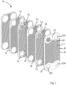
- a heat exchanger 10 according to one embodiment of the present invention is illustrated schematically.
- the heat exchanger 10 comprises an end plate 11 and a plurality of heat exchanger plates 12 stacked in a stack to form the heat exchanger 10.
- the heat exchanger plates 12 are identical.
- the heat exchanger plates 12 are made from sheet metal and are provided with a pattern of ridges R and grooves G such that interplate flow channels for fluids to exchange heat are formed between the plates when the plates are stacked in a stack to form the heat exchanger 10 by providing contact points between at least some crossing ridges and grooves of neighbouring plates 12 under formation of the interplate flow channels for fluids to exchange heat.
- the pattern according to the embodiment of Figs. 1-3 is a herringbone pattern. However, the pattern may also be in the form of obliquely extending straight lines as described below.
- the pattern of ridges R and grooves G is a corrugated pattern having a corrugation depth.
- the pattern is a pressed pattern. The pattern is adapted to keep the plates 12 on a distance from one another, except from the contact points, to form spaces between adjacent heat exchanger plates and the flow channels.
- each of the heat exchanger plates 12 is surrounded by a skirt S, which extends generally perpendicular to a plane of the heat exchanger plate 12 and is adapted to contact skirts of neighbouring plates 12 in order to provide a seal along the circumference of the heat exchanger 10.
- the heat exchanger plates 12 are arranged with port openings 01-04 for letting fluids to exchange heat into and out of the interplate flow channels.
- the end plate 11 and the heat exchanger plates 12 are arranged with four port openings 01-04.
- Port opening areas 13 surrounding the port openings O1 to O4 are provided at different heights, i.e. different levels, such that selective communication between the port openings and the interplate flow channels is achieved.
- the port opening areas 13 are flat.
- the port opening areas 13 are arranged for sealing against a corresponding port opening area 13 of an adjacent heat exchanger plate 12.
- the port openings 01-04 and the port opening areas 13 are arranged in a conventional manner.
- the port opening areas 13 are arranged such that first and second port openings O1 and O2 are in fluid communication with one another through interplate flow channels, whereas the third and fourth large port openings O3 and O4 are in fluid communication with one another by neighboring interplate flow channels.
- the heat exchanger plates 12 are rectangular with rounded corners, wherein the port openings 01-04 are arranged near the corners.
- the heat exchanger plates 12 are square, e.g. with rounded corners.
- the heat exchanger plates 12 are circular, oval or arranged with other suitable shape, wherein the large port openings 01-04 are distributed in a suitable manner.
- each of the heat exchanger plates 12 is formed with four port openings 01-04.
- the heat exchanger plates 12 are formed with another number of ports, such as six, eight or ten.
- the heat exchanger plates 12 are identical and every other plate 12 is turned 180 degrees in its plane in relation to adjacent heat exchanger plates 12.
- the end plate 11 is formed with flat areas 14 with the port openings O1-O4.
- the port openings 01-04 of the end plate 11 are aligned with the port openings of the heat exchanger plates 12 in a conventional manner.
- the end plate 11 comprises a first end section with a first flat area and neighbouring port openings O1 and O3 and a second end section with a second flat area and neighbouring port openings O2 and O4.
- the end plate 11 is a conventional end plate.
- the end plate 11 comprises a central portion having a pattern of ridges (R) and grooves (G) similar to the heat exchanger plates 12.
- the end sections do not have the pattern of ridges and grooves.
- the end sections are formed with the flat areas 14, at least around the port openings O1-O4.
- the port openings 01-04 and the flat areas 14 are arranged in a common plane.
- the flat areas 14 of the end plate 11 form flow channels together with the grooves (G) of the adjacent heat exchanger plate 12, such as a first heat exchanger plate in the stack of heat exchanger plates.
- the flat areas 14 form flow channels together with the neighbouring heat exchanger plate 12 in the vicinity of port opening areas 13 of the neighbouring heat exchanger plate 12.
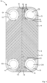
- the heat exchanger plate 12 is provided with indentations 15.
- the indentations 15 are arranged to provide for trans-ridge flow channels.
- the indentations 15 are arranged in ridges R of the heat exchanger plate 12, wherein at least some ridges are formed with at least one indentation 15.
- At least some of the indentations 15 are arranged in the vicinity of the port openings O3, O4 to connect a groove G, which together with the flat area 14 forms a flow channel, with a neighbouring groove G to prevent stagnant media in said flow channel between the heat exchanger plate 12 and the flat area 14 of the end plate 11.
- the indentations 15 are arranged with a depth corresponding to at least 5% of the corrugation depth of the heat exchanger plates 12.
- the depth of the indentations 15 are less than 80% of the corrugation depth.
- the depth of the indentations 15 is 20-80%, 40-80%, 50-80%, 50-60% or 50% of the corrugation depth.
- contact points 16 between the heat exchanger plate 12 and a further heat exchanger plate are illustrated schematically.
- a brazing joint is arranged in the contact points 16, wherein the contact points 16 correspond to brazing joints.
- each contact point 16 between adjacent heat exchanger plates 12 corresponds to a brazing joint.
- the contact points 16 are illustrated on the back side of the heat exchanger plate 12 and the contact points 16 with a neigbouring heat exchanger plate on the front side is understood by a skilled person to be in the corresponding positions on the ridges R as illustrated schematically for a few positions by means of squares in the vicinity of the third port opening O3 in Fig. 3 .
- Fig. 3 As can be seen in Fig.
- the indentations 15 are arranged with a distance to the port opening area 13 of the third port opening O3 and the fourth port opening O4 leaving space for a brazing joint between the indentation 15 and the port opening O3, O4.
- a brazing joint for connecting a heat exchanger plate with a neighbouring heat exchanger plate is arranged between the port opening area 13 and at least one of the indentations 15.
- a plurality of ridges R of the heat exchanger plates 12 is formed with an indentation 15 in an area overlapping a flat area 14 of the end plate 11.
- the indentations 15 of a heat exchanger plate 12 adjacent the end plate 11 connect a flow channel, formed between the flat area 14 of the end plate 11 and the adjacent heat exchanger plate 12, with a neighbouring flow channel to allow distribution of media between them and prevent stagnant media therein.
- brazing joints for connecting neighbouring heat exchanger plates 12 are arranged between the port opening area 13 and at least one of the indentations 15 or a plurality of the indentations 15 or all of them.
- the indentations 15 of the heat exchanger plate 12 are not all placed in the immediate vicinity of the port openings O3, O4.
- every other indentation 15 is placed on a significant distance from the port openings O3, O4.
- at least one indentation 15 or a plurality of indentations 15 is/are arranged at a distance from the nearest port opening area 13 corresponding to a brazing joint, wherein the indentation 15 is arranged immediately adjacent the brazing joint between the indentation 15 and the port opening area 13.
- more indentations 15 are arranged in the vicinity of the port opening area 13 surrounding the fourth port O4 than in the vicinity of the port opening area 13 surrounding the third port opening O3.
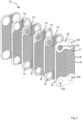
- a second embodiment of a heat exchanger 10 is illustrated, wherein the end plate 11 is similar to the one described above with reference to Fig. 1 . Also, in Fig. 4 some port openings are left out, which is understood by a skilled person.
- the heat exchanger plates 12 are identical and provided with a herringbone pattern of ridges R and grooves G, wherein every other heat exchanger plate 12 is rotated 180 degrees in its plane.
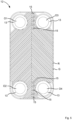
- the heat exchanger plate 12 is provided with a plurality of the indentations 15 forming a trans-ridge channels and connecting neighbouring grooves G.
- the indentations 15 are arranged in ridges R of the heat exchanger plate 12 in the vicinity of and at a distance to the port openings O3, O4 to connect neigbouring grooves G and prevent stagnant media in the flow channels formed between the flat areas 14 and the adjacent heat exchanger plate 12.
- the indentations 15 are arranged with a distance to the port opening area 13 of the third port opening O3 and the fourth port opening O4 leaving space for a brazing joint between the indentation 15 and the port opening O3, O4.
- a brazing joint is arranged between the port opening area 13 and the indentations 15.
- indentations 15 in each end of the plate are provided between contact points 16.
- most of the indentations 15 are arranged between contact points 16.
- at least four or at least five indentations 15 are arranged in the vicinity of the third port opening O3, whereas more, such as at least six or seven, indentations 15 are arranged in the vicinity of the fourth port opening O4.
- the indentations 15 in the vicinity of the third port opening O3 are arranged in a straight line in a longitudinal direction of the heat exchanger plate 12, such as in parallel to a longitudinal centre line of the plate.
- the indentations 15 form a continuous trans-ridge flow channel between the first and last of the indentations 15 in a row of indentations 15.
- the indentations 15 in the vicinity of the fourth port opening O4 are arranged in a corresponding manner, optionally with additional indentations 15 deviating from said straight line.
- the heat exchanger plates 12 are connected to each other by a plurality of rows of contact points 16, wherein a plurality of indentations 15 is arranged between the first and second rows of contact points 16 counted from the nearest port opening area 13.
- indentations 15 are arranged outside the first row of contact points 16.
- a row of indentations 15 forming a continuous trans-ridge flow channel is arranged outside a first row of contact points 16.
- the heat exchanger plate 12 is provided with a plurality of the indentations 15 forming trans-ridge channels in another pattern, wherein a plurality of indentations 15 are distributed between the first port opening O1 and the third port opening O3 between the contact points 16.
- a larger number of indentations 15 are distributed in a similar pattern over a bigger area between the second port opening O2 and the fourth port opening O4.
- the pattern of indentations 15 is a regular pattern.
- FIG. 9 illustrates a first type of heat exchanger plate 12a
- Fig. 10 illustrates a second type of heat exchanger plate 12b.
- the first and second types of heat exchanger plates 12a, 12b are stacked alternatingly and are provided with the end plate 11 to form a heat exchanger 10.
- the first and second types of heat exchanger plates 12a, 12b are provided with a pattern with ridges R and grooves G in the form of obliquely extending straight lines.
- the heat exchanger 10 in the embodiment of Figs.
- 9 and 10 comprises two different types of heat exchanger plates 12a, 12b having a pattern of ridges R and grooves G forming interplate flow channels, wherein flow channels are formed between the flat areas 14 of the end plate 11 and the adjacent heat exchanger plate 12a in the areas between the port openings 01-04, wherein the adjacent heat exchanger plate 12a being of the first type.
- At least the first type of heat exchanger plates 12a is provided with indentations 15 forming trans-ridge flow channels to prevent dead-end flow channels between the flat areas 14 of the end plate and the neighbouring heat exchanger plate 12a.
- indentations 15 are also distributed over a large portion of the first type of heat exchanger plates 12a, including a central heat exchanging area.
- the contact points 16, and thus brazing joints are illustrated schematically on a part of the first type heat exchanger plate 12a.
- the contact points 16 are illustrated for both sides of the plate 12a.
- the indentations 15 in the vicinity of the port openings O1-O4, or at least most of them, are arranged between contact points 16.
- a contact point 16 is provided between the port opening area 13 and the nearest indentation 15 forming a trans-ridge channel connecting neighbouring grooves G in the area overlapping the flat area 14, wherein another contact point 16 is arranged on the ridge R on the other side of the same indentation 15.
- contact points 16 between adjacent heat exchanger plates 12 are arranged immediately before and after an indentation 15 in the area overlapping the flat area 14 of the end plate 11. connecting a flow channel with a neighbouring flow channel.
- indentations 15 of a heat exchanger plate 12a adjacent the end plate 11 connect a flow channel, formed between the flat areas 14 of the end plate 11 and the adjacent heat exchanger plate 12a, with a neighbouring flow channel to allow distribution of media between them and prevent stagnant media therein while brazing joints are arranged between neighbouring heat exchanger plates 12a, 12b in positions between the port opening area 13 and the indentations 15 to provide a strong heat exchanger 10.
Landscapes
- Engineering & Computer Science (AREA)
- Physics & Mathematics (AREA)
- Thermal Sciences (AREA)
- Mechanical Engineering (AREA)
- General Engineering & Computer Science (AREA)
- Heat-Exchange Devices With Radiators And Conduit Assemblies (AREA)
Description
- The present invention relates to a heat exchanger with indentations for avoiding stagnant media. Specifically, the present invention relates to a heat exchanger as defined in the preamble of claim 1, and as illustrated in
WO97/15798A1 - More specifically, the present invention relates to a brazed plate heat exchanger comprising an end plate and a stack of heat exchanger plates provided with a pattern comprising ridges and grooves adapted to form contact points between neighbouring heat exchanger plates such that the heat exchanger plates form interplate flow channels for media to exchange heat over the heat exchanger plates. The heat exchanger plates are further being provided with port openings for selective fluid communication with the flow channels, wherein the port openings are surrounded by port opening areas for sealing against a corresponding port opening area of an adjacent heat exchanger plate. Neighbouring heat exchanger plates are connected by brazing joints at said contact points. The end plate is provided with port openings and flat areas around the port openings in a common plane. A plurality of ridges of the heat exchanger plates, in an area overlapping a flat area of the end plate, are formed with an indentation, wherein said indentations of a heat exchanger plate adjacent the end plate connect a flow channel, formed between the end plate and the adjacent heat exchanger plate, with a neighbouring flow channel to allow distribution of media between them.
- When exchanging heat between different media in any type of heat exchanger, it is generally favourable to avoid stagnant media, i.e. media that does not follow the general flow path but rather stands still. Stagnant media is cumbersome for many reasons: bacterial or microbial growth may occur in the stagnant zones and media may freeze, hence breaking the heat exchanger. Moreover, the general efficiency of the heat exchanger may be impeded. For brazed plate heat exchangers comprising a pressed pattern of ridges and grooves keeping heat exchanger plates on a distance from one another, a historically critical area for the formation of stagnant media is between an end plate having a flat area in the vicinity of the port openings and a neighbouring heat exchanger plate, wherein the end plate forms dead-end flow channels between the end plate and the neighbouring heat exchanger plate where the media easily becomes stagnant.
-
EP0857288 solves the problem with stagnant media in the space between flat areas of an end plate and the neighbouring heat exchanger plate by providing distribution channels between flow channels, which otherwise would be dead-end flow channels, and neighbouring flow channels. The distribution channels allow for a flow that otherwise would be "stuck" in dead-end flow channels. The distribution channels ofEP0857288 are arranged immediately adjacent a port opening area, i.e. at the very end of the ridges. Although the solution disclosed in this patent is efficient for avoiding stagnant media, it has some drawbacks when it comes to strength. - Hence, one problem with prior art heat exchangers is that they are weak and cannot withstand high pressure.
- It is the object of the present invention to provide a brazed plate heat exchanger with reduced risk of stagnant media while increasing the number of contact points between the ridges and grooves of neighbouring plates around port opening areas and hence increase the strength of the heat exchanger.
- The present invention is related to a brazed plate heat exchanger as defined in claim 1.
- By the provision of the indentations, trans-ridge flow channels are formed for distributing media and prevent stagnant media in flow channels that otherwise would be dead-end flow channels in the space between the end plate and the adjacent heat exchanger plate, such as the first or last heat exchanger plate in the stack. In addition it has surprisingly been found that by arranging said indentations with a small distance from the very end of the flow channel, i.e. on the ridge at a distance from the nearest port opening area, space is provided for a contact point and thus a brazing joint, while stagnant media in the flow channel still is prevented. Hence, it has been found that a favourable flow of media is achieved also when a brazing joint is arranged between the indentation and the port opening area. The brazing joints between the port opening area and at least some of the indentations result in a stronger heat exchanger. Also, contact points closer to the port opening areas is achieved, which results in smaller pressure areas around the ports. Additional contact points are achieved. Also, contact points closer to the port openings are achieved. For example, a distance between the port opening and a first row of contact points can be shorter than in the prior art and an area around the port opening exposed to media pressure is smaller. Also, a higher contact point density in the immediate vicinity of the port opening can be achieved. Together this results in a strong heat exchanger while stagnant media in the dead-end flow channels is prevented.
- The end plate can be a conventional end plate with flat areas around the port openings, such as in the end sections of a rectangular end plate. The port openings and the flat areas of the end plate are arranged in a common plane. The end plate can be a front end plate or a back end plate. The flat areas of the end plate can be adapted to be connected to a hydroblock or similar conventional fittings. The end plate can be provided with a pattern of ridges and grooves in a central portion thereof.
- A contact point is arranged on the ridge on both sides of the indentations or a plurality of the indentations connecting a flow channel, which otherwise would form a dead-end flow channel together with the end plate, with a neighbouring flow channel. Hence, a very strong heat exchanger is achieved while preventing stagnant media. Hence, the heat exchanger plates can be connected to each other by a plurality of rows of brazing joints, wherein the indentations or a plurality of indentations can be arranged between the first and second rows of brazing joints counted from the port opening area closest to the indentation.
- In the following, the invention will be described with reference to appended drawings, wherein:
-
Fig. 1 is a schematic exploded view of a heat exchanger according to a first embodiment of the present invention, -
Fig. 2 is a schematic front view of a heat exchanger plate according toFig. 1 , -
Fig. 3 is a schematic front view of the heat exchanger plate ofFig. 2 illustrating imaginary contact points between the illustrated plate and a further heat exchanger plate, -
Fig. 4 is a schematic exploded view of a heat exchanger according to a second embodiment of the present invention, -
Fig. 5 is a schematic front view of a heat exchanger plate according toFig. 4 , -
Fig. 6 is a schematic front view of the heat exchanger plate ofFig. 5 illustrating imaginary contact points between the illustrated plate and a further heat exchanger plate, -
Fig. 7 is a schematic front view of a heat exchanger plate according to a third embodiment, -
Fig. 8 is a schematic front view of the heat exchanger plate ofFig. 7 illustrating imaginary contact points between the illustrated plate and a further heat exchanger plate, -
Figs. 9 and 10 are schematic front views of heat exchanger plates according to another embodiment of the present invention, whereinFig. 9 illustrates one type of plate and -
Fig. 10 another type of plate to be arranged together in an alternating manner, and -
Fig. 11 is a schematic perspective view of a part of a heat exchanger plate according to -
Fig. 9 , illustrating imaginary contact points between the illustrated plate and a further heat exchanger plates in both directions. - With reference to
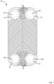
Fig. 1 , aheat exchanger 10 according to one embodiment of the present invention is illustrated schematically. Theheat exchanger 10 comprises anend plate 11 and a plurality ofheat exchanger plates 12 stacked in a stack to form theheat exchanger 10. In the embodiment ofFig. 1 , theheat exchanger plates 12 are identical. - The
heat exchanger plates 12 are made from sheet metal and are provided with a pattern of ridges R and grooves G such that interplate flow channels for fluids to exchange heat are formed between the plates when the plates are stacked in a stack to form theheat exchanger 10 by providing contact points between at least some crossing ridges and grooves of neighbouringplates 12 under formation of the interplate flow channels for fluids to exchange heat. The pattern according to the embodiment ofFigs. 1-3 is a herringbone pattern. However, the pattern may also be in the form of obliquely extending straight lines as described below. The pattern of ridges R and grooves G is a corrugated pattern having a corrugation depth. The pattern is a pressed pattern. The pattern is adapted to keep theplates 12 on a distance from one another, except from the contact points, to form spaces between adjacent heat exchanger plates and the flow channels. - In the illustrated embodiment, each of the
heat exchanger plates 12 is surrounded by a skirt S, which extends generally perpendicular to a plane of theheat exchanger plate 12 and is adapted to contact skirts of neighbouringplates 12 in order to provide a seal along the circumference of theheat exchanger 10. - The
heat exchanger plates 12 are arranged with port openings 01-04 for letting fluids to exchange heat into and out of the interplate flow channels. In the illustrated embodiment, theend plate 11 and theheat exchanger plates 12 are arranged with four port openings 01-04. InFig. 1 some port openings are missing, which is understood by a skilled person and does not affect the disclosure of the present invention.Port opening areas 13 surrounding the port openings O1 to O4 are provided at different heights, i.e. different levels, such that selective communication between the port openings and the interplate flow channels is achieved. For example, theport opening areas 13 are flat. Theport opening areas 13 are arranged for sealing against a correspondingport opening area 13 of an adjacentheat exchanger plate 12. For example, the port openings 01-04 and theport opening areas 13 are arranged in a conventional manner. - In the
heat exchanger 10 ofFig. 1 , theport opening areas 13 are arranged such that first and second port openings O1 and O2 are in fluid communication with one another through interplate flow channels, whereas the third and fourth large port openings O3 and O4 are in fluid communication with one another by neighboring interplate flow channels. In the illustrated embodiment, theheat exchanger plates 12 are rectangular with rounded corners, wherein the port openings 01-04 are arranged near the corners. Alternatively, theheat exchanger plates 12 are square, e.g. with rounded corners. Alternatively, theheat exchanger plates 12 are circular, oval or arranged with other suitable shape, wherein the large port openings 01-04 are distributed in a suitable manner. In the illustrated embodiment, each of theheat exchanger plates 12 is formed with four port openings 01-04. Alternatively, theheat exchanger plates 12 are formed with another number of ports, such as six, eight or ten. In the embodiment ofFig. 1 , theheat exchanger plates 12 are identical and everyother plate 12 is turned 180 degrees in its plane in relation to adjacentheat exchanger plates 12. - The
end plate 11 according toFig. 1 is formed withflat areas 14 with the port openings O1-O4. The port openings 01-04 of theend plate 11 are aligned with the port openings of theheat exchanger plates 12 in a conventional manner. For example, theend plate 11 comprises a first end section with a first flat area and neighbouring port openings O1 and O3 and a second end section with a second flat area and neighbouring port openings O2 and O4. For example, theend plate 11 is a conventional end plate. In the illustrated embodiment, theend plate 11 comprises a central portion having a pattern of ridges (R) and grooves (G) similar to theheat exchanger plates 12. The end sections do not have the pattern of ridges and grooves. Instead the end sections are formed with theflat areas 14, at least around the port openings O1-O4. The port openings 01-04 and theflat areas 14 are arranged in a common plane. Hence, theflat areas 14 of theend plate 11 form flow channels together with the grooves (G) of the adjacentheat exchanger plate 12, such as a first heat exchanger plate in the stack of heat exchanger plates. Theflat areas 14 form flow channels together with the neighbouringheat exchanger plate 12 in the vicinity ofport opening areas 13 of the neighbouringheat exchanger plate 12. - When the
heat exchanger plate 12 and theend plate 11 are mounted in order to form a part of aplate heat exchanger 10, two of theport opening areas 13 will come in contact with theflat areas 14 of theend plate 11. Also, ridges R of theheat exchanger plate 12 will also come in contact with theflat areas 14 of theend plate 11. Hence, flow channels are formed between theflat area 14 in the end section of theend plate 11 and the adjacentheat exchanger plate 12. Flow channels are formed in an area between neighbouring port openings of theheat exchanger plate 12. For example, flow channels are formed between theflat areas 14 and the neighbouringheat exchanger plate 12 by the grooves G connected to the first port opening O1, wherein some grooves (G) ends when said grooves G reach theport openings area 13 around the neighbouring third port opening O3. - With reference also to
Fig. 2 , theheat exchanger plate 12 is provided withindentations 15. Theindentations 15 are arranged to provide for trans-ridge flow channels. Theindentations 15 are arranged in ridges R of theheat exchanger plate 12, wherein at least some ridges are formed with at least oneindentation 15. At least some of theindentations 15 are arranged in the vicinity of the port openings O3, O4 to connect a groove G, which together with theflat area 14 forms a flow channel, with a neighbouring groove G to prevent stagnant media in said flow channel between theheat exchanger plate 12 and theflat area 14 of theend plate 11. By the provision of theindentations 15 dead-end flow channels delimited by ridges R and theflat end sections 14 of theend plate 11 are avoided. Theindentations 15 are arranged with a depth corresponding to at least 5% of the corrugation depth of theheat exchanger plates 12. For example, the depth of theindentations 15 are less than 80% of the corrugation depth. For example, the depth of theindentations 15 is 20-80%, 40-80%, 50-80%, 50-60% or 50% of the corrugation depth. - With reference to
Fig. 3 contact points 16 between theheat exchanger plate 12 and a further heat exchanger plate are illustrated schematically. Generally, a brazing joint is arranged in the contact points 16, wherein the contact points 16 correspond to brazing joints. For example, eachcontact point 16 between adjacentheat exchanger plates 12 corresponds to a brazing joint. InFig. 3 the contact points 16 are illustrated on the back side of theheat exchanger plate 12 and the contact points 16 with a neigbouring heat exchanger plate on the front side is understood by a skilled person to be in the corresponding positions on the ridges R as illustrated schematically for a few positions by means of squares in the vicinity of the third port opening O3 inFig. 3 . As can be seen inFig. 3 at least some of theindentations 15 are arranged with a distance to theport opening area 13 of the third port opening O3 and the fourth port opening O4 leaving space for a brazing joint between theindentation 15 and the port opening O3, O4. Hence, a brazing joint for connecting a heat exchanger plate with a neighbouring heat exchanger plate is arranged between theport opening area 13 and at least one of theindentations 15. A plurality of ridges R of theheat exchanger plates 12 is formed with anindentation 15 in an area overlapping aflat area 14 of theend plate 11. Theindentations 15 of aheat exchanger plate 12 adjacent theend plate 11 connect a flow channel, formed between theflat area 14 of theend plate 11 and the adjacentheat exchanger plate 12, with a neighbouring flow channel to allow distribution of media between them and prevent stagnant media therein. At the same time, in the area overlapping theflat area 14 of theend plate 11, brazing joints for connecting neighbouringheat exchanger plates 12 are arranged between theport opening area 13 and at least one of theindentations 15 or a plurality of theindentations 15 or all of them. - In the embodiment of
Figs. 1-3 theindentations 15 of theheat exchanger plate 12 are not all placed in the immediate vicinity of the port openings O3, O4. For example, everyother indentation 15 is placed on a significant distance from the port openings O3, O4. For example, at least oneindentation 15 or a plurality ofindentations 15 is/are arranged at a distance from the nearestport opening area 13 corresponding to a brazing joint, wherein theindentation 15 is arranged immediately adjacent the brazing joint between theindentation 15 and theport opening area 13. For example,more indentations 15 are arranged in the vicinity of theport opening area 13 surrounding the fourth port O4 than in the vicinity of theport opening area 13 surrounding the third port opening O3. - With reference to
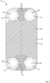
Figs. 4-6 a second embodiment of aheat exchanger 10 is illustrated, wherein theend plate 11 is similar to the one described above with reference toFig. 1 . Also, inFig. 4 some port openings are left out, which is understood by a skilled person. In the embodiment ofFigs. 4-6 theheat exchanger plates 12 are identical and provided with a herringbone pattern of ridges R and grooves G, wherein every otherheat exchanger plate 12 is rotated 180 degrees in its plane. - With reference also to
Fig. 5 , theheat exchanger plate 12 is provided with a plurality of theindentations 15 forming a trans-ridge channels and connecting neighbouring grooves G. In the illustrated embodiment, theindentations 15 are arranged in ridges R of theheat exchanger plate 12 in the vicinity of and at a distance to the port openings O3, O4 to connect neigbouring grooves G and prevent stagnant media in the flow channels formed between theflat areas 14 and the adjacentheat exchanger plate 12. In the embodiment ofFigs. 4-6 all ridges R in the area between the first port opening 1 and the third port opening O3 are provided with anindentation 15 leaving space for acontact point 16, and thus a brazing joint, between theport opening area 13 of the third and fourth port openings O3, O4 and eachindentation 15 as illustrated schematically inFig. 6 . Also inFig. 6 the contact points 16 are illustrated schematically between theheat exchanger plate 12 and a further heat exchanger plate behind the illustrated one, wherein the contact points 16 on the front side towards anotherheat exchanger plate 12 is understood by a skilled person to be in the corresponding positions on the ridges R as illustrated schematically for a few positions by means of squares in the vicinity of the third port opening O3 inFig. 6 . As can be seen inFig. 6 theindentations 15 are arranged with a distance to theport opening area 13 of the third port opening O3 and the fourth port opening O4 leaving space for a brazing joint between theindentation 15 and the port opening O3, O4. Hence, a brazing joint is arranged between theport opening area 13 and theindentations 15. - In the embodiment of
Figs. 4-6 all but one of theindentations 15 in each end of the plate are provided between contact points 16. Hence, most of theindentations 15 are arranged between contact points 16. For example, at least four or at least fiveindentations 15 are arranged in the vicinity of the third port opening O3, whereas more, such as at least six or seven,indentations 15 are arranged in the vicinity of the fourth port opening O4. In the embodiment ofFigs. 4-6 theindentations 15 in the vicinity of the third port opening O3 are arranged in a straight line in a longitudinal direction of theheat exchanger plate 12, such as in parallel to a longitudinal centre line of the plate. For example, theindentations 15 form a continuous trans-ridge flow channel between the first and last of theindentations 15 in a row ofindentations 15. For example, theindentations 15 in the vicinity of the fourth port opening O4 are arranged in a corresponding manner, optionally withadditional indentations 15 deviating from said straight line. For example, theheat exchanger plates 12 are connected to each other by a plurality of rows of contact points 16, wherein a plurality ofindentations 15 is arranged between the first and second rows of contact points 16 counted from the nearestport opening area 13. Hence,indentations 15 are arranged outside the first row of contact points 16. For example, a row ofindentations 15 forming a continuous trans-ridge flow channel is arranged outside a first row of contact points 16. - With reference to
Figs. 7 and8 , theheat exchanger plate 12 is provided with a plurality of theindentations 15 forming trans-ridge channels in another pattern, wherein a plurality ofindentations 15 are distributed between the first port opening O1 and the third port opening O3 between the contact points 16. In the embodiment ofFigs. 7 and8 a larger number ofindentations 15 are distributed in a similar pattern over a bigger area between the second port opening O2 and the fourth port opening O4. For example, the pattern ofindentations 15 is a regular pattern. - With reference to
Figs. 9 and 10 another embodiment of the invention is illustrated, whereinFig. 9 illustrates a first type ofheat exchanger plate 12a andFig. 10 illustrates a second type ofheat exchanger plate 12b. The first and second types ofheat exchanger plates end plate 11 to form aheat exchanger 10. The first and second types ofheat exchanger plates heat exchanger 10 in the embodiment ofFigs. 9 and 10 comprises two different types ofheat exchanger plates flat areas 14 of theend plate 11 and the adjacentheat exchanger plate 12a in the areas between the port openings 01-04, wherein the adjacentheat exchanger plate 12a being of the first type. At least the first type ofheat exchanger plates 12a is provided withindentations 15 forming trans-ridge flow channels to prevent dead-end flow channels between theflat areas 14 of the end plate and the neighbouringheat exchanger plate 12a. In the embodiment ofFigs. 9 and 10 indentations 15 are also distributed over a large portion of the first type ofheat exchanger plates 12a, including a central heat exchanging area. - With reference to
Fig. 11 the contact points 16, and thus brazing joints, are illustrated schematically on a part of the first typeheat exchanger plate 12a. The contact points 16 are illustrated for both sides of theplate 12a. Hence, as can be seen inFig. 11 , theindentations 15 in the vicinity of the port openings O1-O4, or at least most of them, are arranged between contact points 16. Hence, acontact point 16 is provided between theport opening area 13 and thenearest indentation 15 forming a trans-ridge channel connecting neighbouring grooves G in the area overlapping theflat area 14, wherein anothercontact point 16 is arranged on the ridge R on the other side of thesame indentation 15. For example, contact points 16 between adjacentheat exchanger plates 12 are arranged immediately before and after anindentation 15 in the area overlapping theflat area 14 of theend plate 11. connecting a flow channel with a neighbouring flow channel. Hence,indentations 15 of aheat exchanger plate 12a adjacent theend plate 11 connect a flow channel, formed between theflat areas 14 of theend plate 11 and the adjacentheat exchanger plate 12a, with a neighbouring flow channel to allow distribution of media between them and prevent stagnant media therein while brazing joints are arranged between neighbouringheat exchanger plates port opening area 13 and theindentations 15 to provide astrong heat exchanger 10.
Claims (11)
- A brazed plate heat exchanger (10) comprising an end plate (11) and a stack of heat exchanger plates (12, 12a, 12b) provided with a pattern comprising ridges (R) and grooves (G) adapted to form contact points (16) between neighbouring heat exchanger plates such that the heat exchanger plates form interplate flow channels for media to exchange heat over the heat exchanger plates, the heat exchanger plates further being provided with port openings (01-04) for selective fluid communication with the flow channels, wherein the port openings are surrounded by port opening areas (13) for sealing against a corresponding port opening area of a neighbouring heat exchanger plate, wherein neighbouring heat exchanger plates are connected by brazing joints at said contact points (16), wherein the end plate (11) is provided with port openings (O1-O4) and flat areas (14) around the port openings in a common plane, wherein a plurality of ridges (R) of the heat exchanger plates, in an area overlapping any of said flat areas (14) of the end plate (11), are formed with an indentation (15), wherein said indentations (15) of a heat exchanger plate (12, 12a) adjacent the end plate (11) connect a flow channel, formed between the end plate and the adjacent heat exchanger plate (12, 12a), with a neighbouring flow channel to allow distribution of media between them, characterised in that a contact point (16) is arranged on the ridge (R) on both sides of at least one of said indentations (15) connecting a flow channel, formed between the end plate (11) and the adjacent heat exchanger plate (12, 12a), with a neighbouring flow channel to allow distribution of media between them, and that a brazing joint for connecting neighbouring heat exchanger plates is arranged between the port opening area (13) and at least one of said indentations (15).
- A brazed heat exchanger according to claim 1, wherein the heat exchanger plates are connected to each other by a plurality of rows of brazing joints, wherein a plurality of indentations (15) is arranged between the first and second rows of brazing joints counted from the closest port opening area (13).
- A brazed heat exchanger according to any of the preceding claims, wherein a brazing joint for connecting neighbouring heat exchanger plates is arranged immediately adjacent said indentations.
- A brazed heat exchanger according to any of the preceding claims, wherein a brazing joint for connecting neighbouring heat exchanger plates is arranged immediately adjacent said indentations.
- A brazed heat exchanger according to any of the preceding claims, wherein the heat exchanger plates are formed with indentations (15) for connecting at least every other flow channel, formed between the end plate (11) and the adjacent heat exchanger plate (12, 12a), with a neighbouring flow channel to allow distribution of media between them.
- A brazed heat exchanger according to any of the preceding claims, wherein the pattern comprising ridges (R) and grooves (G) are formed with a corrugation depth, and wherein the indentations (15) are formed with a depth corresponding to at least 5% of the corrugation depth.
- A brazed heat exchanger according to any claim 6, wherein the depth of the indentations is 30-80%, 40-60% or 50% of the corrugation depth.
- A brazed heat exchanger according to any of the preceding claims, wherein the end plate (11), in a central portion thereof, is formed with a pattern of ridges and grooves.
- A brazed heat exchanger according to any of the preceding claims, wherein port opening areas (13) of the heat exchanger plates are arranged on different levels.
- A brazed heat exchanger according to any of the preceding claims, wherein said indentations are arranged with a small distance from the very end of the flow channel.
- A brazed heat exchanger according to any of the preceding claims, wherein said indentations are arranged on the ridge at a distance from the nearest port opening area.
Priority Applications (1)
| Application Number | Priority Date | Filing Date | Title |
|---|---|---|---|
| SI202030596T SI4081749T1 (en) | 2019-12-23 | 2020-12-09 | A heat exchanger with indentations for avoiding stagnant media |
Applications Claiming Priority (2)
| Application Number | Priority Date | Filing Date | Title |
|---|---|---|---|
| SE1951549A SE544387C2 (en) | 2019-12-23 | 2019-12-23 | A heat exchanger with indentations for avoiding stagnant media |
| PCT/SE2020/051181 WO2021133237A1 (en) | 2019-12-23 | 2020-12-09 | A heat exchanger with indentations for avoiding stagnant media |
Publications (2)
| Publication Number | Publication Date |
|---|---|
| EP4081749A1 EP4081749A1 (en) | 2022-11-02 |
| EP4081749B1 true EP4081749B1 (en) | 2025-02-26 |
Family
ID=73835685
Family Applications (1)
| Application Number | Title | Priority Date | Filing Date |
|---|---|---|---|
| EP20824709.8A Active EP4081749B1 (en) | 2019-12-23 | 2020-12-09 | A heat exchanger with indentations for avoiding stagnant media |
Country Status (8)
| Country | Link |
|---|---|
| US (1) | US12140384B2 (en) |
| EP (1) | EP4081749B1 (en) |
| JP (1) | JP7724219B2 (en) |
| CN (1) | CN114867979B (en) |
| PL (1) | PL4081749T3 (en) |
| SE (1) | SE544387C2 (en) |
| SI (1) | SI4081749T1 (en) |
| WO (1) | WO2021133237A1 (en) |
Citations (6)
| Publication number | Priority date | Publication date | Assignee | Title |
|---|---|---|---|---|
| US4605060A (en) | 1981-11-26 | 1986-08-12 | Alfa-Laval Ab | Heat exchanger plate |
| WO1997015798A1 (en) | 1995-10-23 | 1997-05-01 | Swep International Ab | A plate heat exchanger |
| WO2007024191A1 (en) | 2005-08-26 | 2007-03-01 | Swep International Ab | End plate for plate heat exchanger |
| WO2007073304A1 (en) | 2005-12-22 | 2007-06-28 | Alfa Laval Corporate Ab | Heat transfer plate for plate heat exchanger with even load distribution in port regions |
| WO2015062992A1 (en) | 2013-10-29 | 2015-05-07 | Swep International Ab | A method of brazing a plate heat exchanger using screen printed brazing material; a plate heat exchanger manufactured by such method |
| WO2015086343A1 (en) | 2013-12-10 | 2015-06-18 | Swep International Ab | Heat exchanger with improved flow |
Family Cites Families (8)
| Publication number | Priority date | Publication date | Assignee | Title |
|---|---|---|---|---|
| US7461448B2 (en) | 2005-08-17 | 2008-12-09 | Simon Schwartzman | Crimping tool with quick-change crimp head for sealing and electrically crimping electrical contacts to insulated wire |
| PT2257758E (en) * | 2008-04-04 | 2014-09-16 | Alfa Laval Corp Ab | A plate heat exchanger |
| CN102245991B (en) * | 2008-12-17 | 2013-07-03 | 舒瑞普国际股份公司 | Port opening of brazed heat exchanger |
| FR2954480B1 (en) * | 2009-12-17 | 2012-12-07 | Valeo Systemes Thermiques | HEAT EXCHANGER PLATE, IN PARTICULAR FOR AN AIR CONDITIONING CONDENSER |
| JP5419719B2 (en) * | 2010-01-04 | 2014-02-19 | 三菱電機株式会社 | Plate heat exchanger and heat pump device |
| US8869398B2 (en) * | 2011-09-08 | 2014-10-28 | Thermo-Pur Technologies, LLC | System and method for manufacturing a heat exchanger |
| SE541412C2 (en) * | 2013-09-17 | 2019-09-24 | Swep Int Ab | A plate heat exchanger having reinforcing means |
| SE542528C2 (en) | 2016-12-16 | 2020-06-02 | Swep Int Ab | Brazed plate heat exchanger with a temperature sensor |
-
2019
- 2019-12-23 SE SE1951549A patent/SE544387C2/en unknown
-
2020
- 2020-12-09 SI SI202030596T patent/SI4081749T1/en unknown
- 2020-12-09 JP JP2022536984A patent/JP7724219B2/en active Active
- 2020-12-09 EP EP20824709.8A patent/EP4081749B1/en active Active
- 2020-12-09 WO PCT/SE2020/051181 patent/WO2021133237A1/en not_active Ceased
- 2020-12-09 CN CN202080089475.6A patent/CN114867979B/en active Active
- 2020-12-09 PL PL20824709.8T patent/PL4081749T3/en unknown
- 2020-12-09 US US17/784,259 patent/US12140384B2/en active Active
Patent Citations (6)
| Publication number | Priority date | Publication date | Assignee | Title |
|---|---|---|---|---|
| US4605060A (en) | 1981-11-26 | 1986-08-12 | Alfa-Laval Ab | Heat exchanger plate |
| WO1997015798A1 (en) | 1995-10-23 | 1997-05-01 | Swep International Ab | A plate heat exchanger |
| WO2007024191A1 (en) | 2005-08-26 | 2007-03-01 | Swep International Ab | End plate for plate heat exchanger |
| WO2007073304A1 (en) | 2005-12-22 | 2007-06-28 | Alfa Laval Corporate Ab | Heat transfer plate for plate heat exchanger with even load distribution in port regions |
| WO2015062992A1 (en) | 2013-10-29 | 2015-05-07 | Swep International Ab | A method of brazing a plate heat exchanger using screen printed brazing material; a plate heat exchanger manufactured by such method |
| WO2015086343A1 (en) | 2013-12-10 | 2015-06-18 | Swep International Ab | Heat exchanger with improved flow |
Non-Patent Citations (1)
| Title |
|---|
| D7 - EXPERT OPINION BY MR. PER SJÖDIN |
Also Published As
| Publication number | Publication date |
|---|---|
| JP2023507732A (en) | 2023-02-27 |
| CN114867979A (en) | 2022-08-05 |
| EP4081749A1 (en) | 2022-11-02 |
| PL4081749T3 (en) | 2025-06-30 |
| US20230043151A1 (en) | 2023-02-09 |
| JP7724219B2 (en) | 2025-08-15 |
| SI4081749T1 (en) | 2025-05-30 |
| SE1951549A1 (en) | 2021-06-24 |
| SE544387C2 (en) | 2022-05-03 |
| WO2021133237A1 (en) | 2021-07-01 |
| US12140384B2 (en) | 2024-11-12 |
| CN114867979B (en) | 2025-07-18 |
Similar Documents
| Publication | Publication Date | Title |
|---|---|---|
| US6305466B1 (en) | Three circuit plate heat exchanger | |
| EP4182624B1 (en) | A double wall plate heat exchanger | |
| EP3080541B1 (en) | Heat exchanger with improved flow | |
| EP3615878B1 (en) | Heat transfer plate and heat exchanger comprising a plurality of such heat transfer plates | |
| US20040168793A1 (en) | Plate heat exchanger | |
| EP3017261B1 (en) | Asymmetrical exchanger with ancillary channels for connecting turns | |
| EP3115733B1 (en) | Heat exchange plate for plate-type heat exchanger and plate-type heat exchanger provided with said heat exchange plate | |
| CN110073163B (en) | Plate heat exchanger | |
| EP4081749B1 (en) | A heat exchanger with indentations for avoiding stagnant media | |
| WO2025212012A1 (en) | A heat exchanger plate and a brazed plate heat exchanger comprising such plates |
Legal Events
| Date | Code | Title | Description |
|---|---|---|---|
| STAA | Information on the status of an ep patent application or granted ep patent |
Free format text: STATUS: UNKNOWN |
|
| STAA | Information on the status of an ep patent application or granted ep patent |
Free format text: STATUS: THE INTERNATIONAL PUBLICATION HAS BEEN MADE |
|
| PUAI | Public reference made under article 153(3) epc to a published international application that has entered the european phase |
Free format text: ORIGINAL CODE: 0009012 |
|
| STAA | Information on the status of an ep patent application or granted ep patent |
Free format text: STATUS: REQUEST FOR EXAMINATION WAS MADE |
|
| 17P | Request for examination filed |
Effective date: 20220707 |
|
| AK | Designated contracting states |
Kind code of ref document: A1 Designated state(s): AL AT BE BG CH CY CZ DE DK EE ES FI FR GB GR HR HU IE IS IT LI LT LU LV MC MK MT NL NO PL PT RO RS SE SI SK SM TR |
|
| DAV | Request for validation of the european patent (deleted) | ||
| DAX | Request for extension of the european patent (deleted) | ||
| P01 | Opt-out of the competence of the unified patent court (upc) registered |
Effective date: 20230529 |
|
| GRAP | Despatch of communication of intention to grant a patent |
Free format text: ORIGINAL CODE: EPIDOSNIGR1 |
|
| STAA | Information on the status of an ep patent application or granted ep patent |
Free format text: STATUS: GRANT OF PATENT IS INTENDED |
|
| INTG | Intention to grant announced |
Effective date: 20240930 |
|
| GRAS | Grant fee paid |
Free format text: ORIGINAL CODE: EPIDOSNIGR3 |
|
| GRAA | (expected) grant |
Free format text: ORIGINAL CODE: 0009210 |
|
| STAA | Information on the status of an ep patent application or granted ep patent |
Free format text: STATUS: THE PATENT HAS BEEN GRANTED |
|
| AK | Designated contracting states |
Kind code of ref document: B1 Designated state(s): AL AT BE BG CH CY CZ DE DK EE ES FI FR GB GR HR HU IE IS IT LI LT LU LV MC MK MT NL NO PL PT RO RS SE SI SK SM TR |
|
| REG | Reference to a national code |
Ref country code: GB Ref legal event code: FG4D |
|
| REG | Reference to a national code |
Ref country code: CH Ref legal event code: EP |
|
| REG | Reference to a national code |
Ref country code: DE Ref legal event code: R096 Ref document number: 602020046889 Country of ref document: DE |
|
| REG | Reference to a national code |
Ref country code: IE Ref legal event code: FG4D |
|
| REG | Reference to a national code |
Ref country code: SE Ref legal event code: TRGR |
|
| REG | Reference to a national code |
Ref country code: NL Ref legal event code: MP Effective date: 20250226 |
|
| PG25 | Lapsed in a contracting state [announced via postgrant information from national office to epo] |
Ref country code: RS Free format text: LAPSE BECAUSE OF FAILURE TO SUBMIT A TRANSLATION OF THE DESCRIPTION OR TO PAY THE FEE WITHIN THE PRESCRIBED TIME-LIMIT Effective date: 20250526 |
|
| PG25 | Lapsed in a contracting state [announced via postgrant information from national office to epo] |
Ref country code: FI Free format text: LAPSE BECAUSE OF FAILURE TO SUBMIT A TRANSLATION OF THE DESCRIPTION OR TO PAY THE FEE WITHIN THE PRESCRIBED TIME-LIMIT Effective date: 20250226 |
|
| PG25 | Lapsed in a contracting state [announced via postgrant information from national office to epo] |
Ref country code: ES Free format text: LAPSE BECAUSE OF FAILURE TO SUBMIT A TRANSLATION OF THE DESCRIPTION OR TO PAY THE FEE WITHIN THE PRESCRIBED TIME-LIMIT Effective date: 20250226 |
|
| REG | Reference to a national code |
Ref country code: LT Ref legal event code: MG9D |
|
| PG25 | Lapsed in a contracting state [announced via postgrant information from national office to epo] |
Ref country code: IS Free format text: LAPSE BECAUSE OF FAILURE TO SUBMIT A TRANSLATION OF THE DESCRIPTION OR TO PAY THE FEE WITHIN THE PRESCRIBED TIME-LIMIT Effective date: 20250626 Ref country code: NO Free format text: LAPSE BECAUSE OF FAILURE TO SUBMIT A TRANSLATION OF THE DESCRIPTION OR TO PAY THE FEE WITHIN THE PRESCRIBED TIME-LIMIT Effective date: 20250526 |
|
| PG25 | Lapsed in a contracting state [announced via postgrant information from national office to epo] |
Ref country code: NL Free format text: LAPSE BECAUSE OF FAILURE TO SUBMIT A TRANSLATION OF THE DESCRIPTION OR TO PAY THE FEE WITHIN THE PRESCRIBED TIME-LIMIT Effective date: 20250226 |
|
| PG25 | Lapsed in a contracting state [announced via postgrant information from national office to epo] |
Ref country code: HR Free format text: LAPSE BECAUSE OF FAILURE TO SUBMIT A TRANSLATION OF THE DESCRIPTION OR TO PAY THE FEE WITHIN THE PRESCRIBED TIME-LIMIT Effective date: 20250226 |
|
| REG | Reference to a national code |
Ref country code: SK Ref legal event code: T3 Ref document number: E 46462 Country of ref document: SK |
|
| PG25 | Lapsed in a contracting state [announced via postgrant information from national office to epo] |
Ref country code: LV Free format text: LAPSE BECAUSE OF FAILURE TO SUBMIT A TRANSLATION OF THE DESCRIPTION OR TO PAY THE FEE WITHIN THE PRESCRIBED TIME-LIMIT Effective date: 20250226 Ref country code: PT Free format text: LAPSE BECAUSE OF FAILURE TO SUBMIT A TRANSLATION OF THE DESCRIPTION OR TO PAY THE FEE WITHIN THE PRESCRIBED TIME-LIMIT Effective date: 20250626 |
|
| PG25 | Lapsed in a contracting state [announced via postgrant information from national office to epo] |
Ref country code: BG Free format text: LAPSE BECAUSE OF FAILURE TO SUBMIT A TRANSLATION OF THE DESCRIPTION OR TO PAY THE FEE WITHIN THE PRESCRIBED TIME-LIMIT Effective date: 20250226 Ref country code: GR Free format text: LAPSE BECAUSE OF FAILURE TO SUBMIT A TRANSLATION OF THE DESCRIPTION OR TO PAY THE FEE WITHIN THE PRESCRIBED TIME-LIMIT Effective date: 20250527 |
|
| REG | Reference to a national code |
Ref country code: AT Ref legal event code: MK05 Ref document number: 1770994 Country of ref document: AT Kind code of ref document: T Effective date: 20250226 |
|
| PG25 | Lapsed in a contracting state [announced via postgrant information from national office to epo] |
Ref country code: SM Free format text: LAPSE BECAUSE OF FAILURE TO SUBMIT A TRANSLATION OF THE DESCRIPTION OR TO PAY THE FEE WITHIN THE PRESCRIBED TIME-LIMIT Effective date: 20250226 |
|
| PG25 | Lapsed in a contracting state [announced via postgrant information from national office to epo] |
Ref country code: DK Free format text: LAPSE BECAUSE OF FAILURE TO SUBMIT A TRANSLATION OF THE DESCRIPTION OR TO PAY THE FEE WITHIN THE PRESCRIBED TIME-LIMIT Effective date: 20250226 |
|
| PG25 | Lapsed in a contracting state [announced via postgrant information from national office to epo] |
Ref country code: AT Free format text: LAPSE BECAUSE OF FAILURE TO SUBMIT A TRANSLATION OF THE DESCRIPTION OR TO PAY THE FEE WITHIN THE PRESCRIBED TIME-LIMIT Effective date: 20250226 |
|
| PG25 | Lapsed in a contracting state [announced via postgrant information from national office to epo] |
Ref country code: EE Free format text: LAPSE BECAUSE OF FAILURE TO SUBMIT A TRANSLATION OF THE DESCRIPTION OR TO PAY THE FEE WITHIN THE PRESCRIBED TIME-LIMIT Effective date: 20250226 |
|
| PG25 | Lapsed in a contracting state [announced via postgrant information from national office to epo] |
Ref country code: RO Free format text: LAPSE BECAUSE OF FAILURE TO SUBMIT A TRANSLATION OF THE DESCRIPTION OR TO PAY THE FEE WITHIN THE PRESCRIBED TIME-LIMIT Effective date: 20250226 |
|
| REG | Reference to a national code |
Ref country code: DE Ref legal event code: R026 Ref document number: 602020046889 Country of ref document: DE |
|
| PLBI | Opposition filed |
Free format text: ORIGINAL CODE: 0009260 |
|
| PLAX | Notice of opposition and request to file observation + time limit sent |
Free format text: ORIGINAL CODE: EPIDOSNOBS2 |