EP4081711B1 - Asymmetric bistable shape memory alloy inertial actuator - Google Patents
Asymmetric bistable shape memory alloy inertial actuator Download PDFInfo
- Publication number
- EP4081711B1 EP4081711B1 EP22707721.1A EP22707721A EP4081711B1 EP 4081711 B1 EP4081711 B1 EP 4081711B1 EP 22707721 A EP22707721 A EP 22707721A EP 4081711 B1 EP4081711 B1 EP 4081711B1
- Authority
- EP
- European Patent Office
- Prior art keywords
- crank
- shape memory
- memory alloy
- rod mechanism
- inertial
- Prior art date
- Legal status (The legal status is an assumption and is not a legal conclusion. Google has not performed a legal analysis and makes no representation as to the accuracy of the status listed.)
- Active
Links
Images





Classifications
-
- F—MECHANICAL ENGINEERING; LIGHTING; HEATING; WEAPONS; BLASTING
- F03—MACHINES OR ENGINES FOR LIQUIDS; WIND, SPRING, OR WEIGHT MOTORS; PRODUCING MECHANICAL POWER OR A REACTIVE PROPULSIVE THRUST, NOT OTHERWISE PROVIDED FOR
- F03G—SPRING, WEIGHT, INERTIA OR LIKE MOTORS; MECHANICAL-POWER PRODUCING DEVICES OR MECHANISMS, NOT OTHERWISE PROVIDED FOR OR USING ENERGY SOURCES NOT OTHERWISE PROVIDED FOR
- F03G7/00—Mechanical-power-producing mechanisms, not otherwise provided for or using energy sources not otherwise provided for
- F03G7/06—Mechanical-power-producing mechanisms, not otherwise provided for or using energy sources not otherwise provided for using expansion or contraction of bodies due to heating, cooling, moistening, drying or the like
- F03G7/063—Mechanical-power-producing mechanisms, not otherwise provided for or using energy sources not otherwise provided for using expansion or contraction of bodies due to heating, cooling, moistening, drying or the like characterised by the mechanic interaction
-
- F—MECHANICAL ENGINEERING; LIGHTING; HEATING; WEAPONS; BLASTING
- F03—MACHINES OR ENGINES FOR LIQUIDS; WIND, SPRING, OR WEIGHT MOTORS; PRODUCING MECHANICAL POWER OR A REACTIVE PROPULSIVE THRUST, NOT OTHERWISE PROVIDED FOR
- F03G—SPRING, WEIGHT, INERTIA OR LIKE MOTORS; MECHANICAL-POWER PRODUCING DEVICES OR MECHANISMS, NOT OTHERWISE PROVIDED FOR OR USING ENERGY SOURCES NOT OTHERWISE PROVIDED FOR
- F03G7/00—Mechanical-power-producing mechanisms, not otherwise provided for or using energy sources not otherwise provided for
- F03G7/06—Mechanical-power-producing mechanisms, not otherwise provided for or using energy sources not otherwise provided for using expansion or contraction of bodies due to heating, cooling, moistening, drying or the like
- F03G7/061—Mechanical-power-producing mechanisms, not otherwise provided for or using energy sources not otherwise provided for using expansion or contraction of bodies due to heating, cooling, moistening, drying or the like characterised by the actuating element
- F03G7/0614—Mechanical-power-producing mechanisms, not otherwise provided for or using energy sources not otherwise provided for using expansion or contraction of bodies due to heating, cooling, moistening, drying or the like characterised by the actuating element using shape memory elements
- F03G7/06143—Wires
-
- F—MECHANICAL ENGINEERING; LIGHTING; HEATING; WEAPONS; BLASTING
- F03—MACHINES OR ENGINES FOR LIQUIDS; WIND, SPRING, OR WEIGHT MOTORS; PRODUCING MECHANICAL POWER OR A REACTIVE PROPULSIVE THRUST, NOT OTHERWISE PROVIDED FOR
- F03G—SPRING, WEIGHT, INERTIA OR LIKE MOTORS; MECHANICAL-POWER PRODUCING DEVICES OR MECHANISMS, NOT OTHERWISE PROVIDED FOR OR USING ENERGY SOURCES NOT OTHERWISE PROVIDED FOR
- F03G7/00—Mechanical-power-producing mechanisms, not otherwise provided for or using energy sources not otherwise provided for
- F03G7/06—Mechanical-power-producing mechanisms, not otherwise provided for or using energy sources not otherwise provided for using expansion or contraction of bodies due to heating, cooling, moistening, drying or the like
- F03G7/064—Mechanical-power-producing mechanisms, not otherwise provided for or using energy sources not otherwise provided for using expansion or contraction of bodies due to heating, cooling, moistening, drying or the like characterised by its use
-
- F—MECHANICAL ENGINEERING; LIGHTING; HEATING; WEAPONS; BLASTING
- F05—INDEXING SCHEMES RELATING TO ENGINES OR PUMPS IN VARIOUS SUBCLASSES OF CLASSES F01-F04
- F05B—INDEXING SCHEME RELATING TO WIND, SPRING, WEIGHT, INERTIA OR LIKE MOTORS, TO MACHINES OR ENGINES FOR LIQUIDS COVERED BY SUBCLASSES F03B, F03D AND F03G
- F05B2260/00—Function
- F05B2260/50—Kinematic linkage, i.e. transmission of position
- F05B2260/502—Kinematic linkage, i.e. transmission of position involving springs
-
- F—MECHANICAL ENGINEERING; LIGHTING; HEATING; WEAPONS; BLASTING
- F05—INDEXING SCHEMES RELATING TO ENGINES OR PUMPS IN VARIOUS SUBCLASSES OF CLASSES F01-F04
- F05B—INDEXING SCHEME RELATING TO WIND, SPRING, WEIGHT, INERTIA OR LIKE MOTORS, TO MACHINES OR ENGINES FOR LIQUIDS COVERED BY SUBCLASSES F03B, F03D AND F03G
- F05B2280/00—Materials; Properties thereof
- F05B2280/50—Intrinsic material properties or characteristics
- F05B2280/5006—Shape memory
Definitions
- the present invention relates to an asymmetric bistable inertial actuator, its method of operation and its use in devices, and in particular to an actuator in which the driven element is moved by one or more wires made from a shape memory alloy (indicated in the following as "SMA").
- SMA shape memory alloy
- the shape memory phenomenon consists in the fact that a mechanical piece made of an alloy that exhibits said phenomenon is capable of transitioning, upon a temperature change, between two shapes that are preset at the time of manufacturing, in a very short time and without intermediate equilibrium positions.
- a first mode in which the phenomenon may occur is called "one-way" in that the mechanical piece can change shape in a single direction upon the temperature change, e.g. passing from shape A to shape B, whereas the reverse transition from shape B to shape A requires the application of a mechanical force.
- both transitions can be caused by temperature changes; this occurs thanks to the transformation of the microcrystalline structure of the piece that passes from a type called martensitic, stable at lower temperatures, to a type called austenitic, stable at higher temperatures, and vice versa (M/A and A/M transition).
- Mf Martensite final
- Ms Martensite start
- Au Austenite start
- Austenite final Af
- a SMA wire has to be trained so that it can exhibit its features of shape memory element, and the training process of a SMA wire usually allows to induce in a highly repeatable manner a martensite/austenite (M/A) phase transition when the wire is heated and to induce an austenite/martensite (A/M) phase transition when the wire is cooled.
- M/A martensite/austenite
- A/M austenite/martensite
- bistable SMA wire actuators are described in US 4544988 , US 5977858 , US 6943653 and EP 2735013 , in the applicant's name, all describing solutions with two SMA wires.
- bistable SMA actuator Another example of a bistable SMA actuator is described in US 4965545 , where the bistable behavior is achieved through the use of SMA wires in antagonistic configuration, EP 1593844 using a SMA wire acting on a rotating element with a spring as stability locker, or GB 2558618 showing two SMA wires in antagonistic configuration to switch the inclination of a rocker having a fixed pivoting element placed in its mid portion.
- an actuator exploiting the Joule effect for moving the actuator from a first position to a second position, and then using as suitable mechanism for the switch-back to the first position a SMA actuation either via current control or through an increase in the environment temperature (T>Af).
- An exemplary advantageous application of this concept is an electrical relay in which there is an automatic disengagement of the actuator if the temperature is too high and representative of a dangerous situation (fire).
- the purpose of the present invention is to overcome the drawbacks of prior art actuators, with particular reference to the capability to prevent accidental actuation linked to environment temperature variations but preserving temperature-related safety features, and in a first aspect thereof consist in an asymmetric inertial bistable shape memory alloy actuator comprising the elements recited in claim 1.
- the asymmetric inertial bistable shape memory alloy actuator is configured such that the d2/d1 ratio is comprised between 0.05 and 0.70, preferably between 0.10 and 0.30, with d1 defined as the distance between the crank pin and the dead center of the crank-and-rod mechanism in the first stable position, and d2 defined as the analogous distance in the second stable position.
- the different distance in the two actuator stable positions is the key concept of the present invention and ensures the asymmetric behavior of the actuator.
- Such force may be given by:
- the transition from the first stable position to the second stable position can happen only upon fast actuation of the shape memory alloy wire and is essentially solely inertia-driven, whereas the return or switch-back from the second stable position to the first stable position requires at least a second force contribution to the SMA wire action, such additional force being provided by weight or at least one magnet, or the sum of weight and magnetic action.
- FIG. 1A A schematic representation of a first embodiment of an asymmetric bistable shape memory alloy actuator 100 according to the present invention is shown in figures 1A (first stable position) and 1B (second stable position).
- Actuator 100 comprises a stationary support 11, a movable slider 12 having a first end 12' and a second end 12", a slider guide 13 fixed to the stationary support 11, and a rotatable lever 14 with one unrestrained extremity contacting the stationary support 11 through an end-stop 111 and the other one fixed to the stationary support 11 via a pivot 14'.
- the unrestrained extremity of the rotatable lever 14 also contacts the first end 12' of the movable slider 12 and moves it in a first direction (to the right in the illustrated example) upon actuation of a shape memory alloy wire 15 having a U-shape configuration, with its extremities fixed onto the stationary support 11 via terminals 15' and its central portion connected to the rotatable lever 14.
- Slider 12 is biased towards the first stable position by means of a spring 16 having a first end 16' connected to slider 12 and a second end 16" connected to the stationary support 11, said biasing spring 16 being lodged in a suitable cavity in slider 12.
- Other alternative means could be used to perform said biasing action, such as magnetic means or gravitational means (e.g. a mass connected to the first end 12' by a cable passing over a pulley).
- Actuator 100 comprises a crank-and-rod mechanism 17 for controlling the movement of an inertial element 19 of mass M arranged at the crank pin, i.e. at the vertically movable pivoting connection between the crank and the rod. More specifically, a first movable arm 17' of the crank-and-rod mechanism 17 acts as crank and is connected between element 19 and a first pivot 18' fixed to support 11, and a second movable arm 17" of the crank-and-rod mechanism 17 acts as connecting rod and is connected between element 19 and a second pivot 18" fixed to slider 12 via a suitable coupler 170.
- crank-and-rod mechanism 17 and slider 12 form an inverted slider-crank linkage, in which the sliding movement of slider 12 along guide 13 in a first direction starting from the first stable position of Fig. 1A results in a counter-clockwise rotation of crank 17' around pivot 18'.
- the actuation of the shape memory alloy wire 15 is such that the crank-and-rod mechanism 17 is brought onto its dead center ( figure 1C ) with the first crank-and-rod movable arm 17' aligned with the second crank-and-rod movable arm 17". From there, actuator 100 is capable to move from the first stable position ( figure 1A ) to the second stable position ( figure 1B ) only if the SMA wire 15 is rapidly actuated and the inertial element 19 of mass M is accelerated to move from the first stable position to the second stable position.
- the switch-back from the second stable position to the first stable position is once again achieved by actuation of the shape memory alloy wire 15 against the resistance of spring 16, to bring the crank-and-rod mechanism 17 to its dead center through a clockwise rotation of crank 17' around pivot 18'.
- it is the weight force acting on the inertial element 19 of mass M that brings the crank-and-rod mechanism 17 out of the dead center, and consequently slider 12 in the first stable position of figure 1A .
- the transition from the second stable position to the first stable position just requires the SMA wire actuation, no matter the mode (Joule or heating from the surrounding environment) or its actuation speed.
- the present invention is not limited to a specific way to connect the SMA wire 15 to the rotatable lever 14. Some of the more common configurations are shown in the schematic views of figures 2A-2D .
- figure 2A shows the connection used in figures 1A-1B , with a SMA wire 15 in a U configuration wound over the rotatable lever 14.
- a SMA wire 15 is fixed directly to the rotatable lever 14 in the so called "V-shape configuration".
- Figure 2D shows the simplest alternative with a SMA wire 15 in a straight configuration.
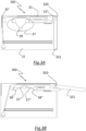
- FIGS. 3A and 3B show a schematic representation of a second embodiment of an asymmetric inertial bistable shape memory alloy actuator 300 in its two stable positions.
- the second end 32" of slider 32 drives a lever 321 mounted on support 31 through a pivot 320 so as to extend the "reach" of the actuator amplifying its stroke.
- first pivot 38' of the crank-and-rod mechanism 37 acts as an end-stop for the first end 32' of slider 32
- the second pivot 38" is directly connect to slider 32, such that both arms 37', 37" and the inertial element 39 are located within slider 32 in the second stable position of Fig.3B .
- Figures 4A and 4B show a schematic representation of a third embodiment of the present invention in which an inertial bistable actuator 400 includes a slider 42 that is longer than the stationary support 41. More specifically, in the first stable position of figure 4A the first end 42' of slider 42 sticks out from the left of support 41, whereas in the second stable position of figure 4B the second end 42" sticks out from the right of support 41.
- the rotatable lever 44 acts on slider 42 by impinging on a suitable internal pin 420 of the latter rather than on the first end 42'.
- the bistable asymmetric inertial actuator 400 also presents a return spring 440 acting on the rotatable lever 44 so as to bring it back to the starting position against an end-stop 411 once the SMA wire 45 is deactivated. In this way, the SMA wire 45 does not remain loose when the actuator is in the second stable position, as in the first two embodiments, in case that could cause problems with adjacent elements that might be touched by the loose wire.
- FIGS 5A and 5B show a schematic representation of a fourth embodiment of the present invention in which an inertial bistable actuator 500 includes a slider 52 that is much shorter than the stationary support 51. More specifically, the crank-and-rod mechanism 57 is placed to the side of slider 52, i.e. the first pivot 58' is to the left of the first end 52' with the second pivot 58" directly connected thereto, and the shape memory alloy wire 55 is directly connected to crank 57' of the crank-and-rod mechanism 57 thus dispensing with the rotatable lever used in the previous embodiments.
- FIGS 6A and 6B show a schematic representation of a fifth embodiment of the present invention in which an inertial bistable actuator 600 includes a slider 62 that is connected directly to the inertial element 69 joining the first and second arms 67', 67" of the crank-and-rod mechanism.
- Slider 62 extends along the direction of movement of the inertial element 69 to which it is connected at one end, while the opposite end is located between guide elements 63.
- Two levers 64, 64' are connected at their proximal ends respectively to the first and second pivots 68', 68" of the crank-and-rod mechanism, and are connected at their opposite distal portions respectively to stoppers 640 and 640' that are fixed on a stationary support 61.
- the actuation of the SMA wire is so fast and short, in the order of some milliseconds, that it just provides the initial impulse to accelerate the crank-and-rod mechanism enough to pass the dead center, therefore it does not oppose the movement of the actuator towards the second stable position.
- the SMA wire 55 arrives to be aligned with crank 57' it is already no longer activated and does not oppose the counter-clockwise rotation of crank 57' towards the second stable position.
- the SMA wire has already been deactivated.
- the various embodiments illustrated above may be combined differently to obtain further embodiments not shown in the figures without departing from the scope and effect of present invention.
- the pivoted lever 321 of the second embodiment could be used also in the first, third and fourth embodiments, or the leverless configuration of the fourth embodiment with the SMA wire directly connected to the crank could be used also in the first three embodiments.
- the inertial mass M is simply connected to the crank-and-rod mechanism and not part or constituent of the crank pin, as depicted in all the embodiments.
- the inertial mass M may be an equivalent mass from a series of masses present in the actuator, i.e. the sum of the contribution of two or more masses placed within the actuator preferably in symmetrical positions.
- the inertial mass M is given by two masses disposed symmetrically with respect to the crank pin on the crank and rod and connected thereon.
- the movement from the first stable position to the second stable position is caused by the fast actuation of the SMA wire, and the return from the second stable position to the first stable position is enabled by the weight force associated with the inertial mass M regardless of the actuation speed of the SMA wire.
- this imposes a constraint on the way the actuator is mounted since the direction of the weight force shall be directed from the second stable position to the first stable position and it will be essentially parallel to the plane in which the crank-and-rod mechanism, and thus the inertial mass M, moves between the first and second stable positions (taking the center of the inertial mass as reference point for the plane).
- the term "essentially parallel” indicates a situation in which the above elements are parallel or form an angle equal to or less than 45°, preferably less than 20°.
- An asymmetric bistable shape memory alloy actuator is capable to allow for a higher degree of mounting freedom by using an inertial element and/or a crank-and-rod mechanism that is also magnetic or capable to respond to a magnetic field, i.e. being a magnetic element itself or capable of being attracted by a magnet.
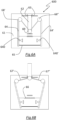
- Figure 7 shows an inertial asymmetric bistable shape memory actuator 700 that is a replica of the actuator of figure 1B in its second stable position with the addition of a magnet 79' fixed onto the stationary support 71 to allow the non-inertial return from the second stable position to the first stable position of the inertial element 79, and consequently of slider 72, also when the actuator is mounted beyond the above-mentioned 45° limit.
- the inertial element 79 is made of or comprises a magnetic element of opposite polarity or a ferromagnetic material capable of being attracted by magnet 79'.
- Fig.8 shows an inertial asymmetric bistable shape memory actuator 800 that is a replica of the actuator of figure 6B in its second stable position with the addition of a couple of magnets 89', 89" fixed onto the stationary support 81 and symmetrically positioned with respect to the inertial element 89 to allow the non-inertial return of the latter, and consequently of slider 82, from the second stable position to the first stable position.
- the inertial element 89 is made of or comprises a magnetic element of opposite polarity or a ferromagnetic element capable of being attracted by magnets 89' and 89".
- FIGS 7 and 8 show the addition of one or two magnets to the first and fifth embodiments respectively, it is clear that the same addition can be made also to the other embodiments and that the exact number and arrangement of the magnets can be adapted to the specific performance requirements of the actuator.
- the magnet(s) is/are preferably placed between the first stable position of the crank pin and the dead center at a distance from the latter comprised between 1/10 and 9/10 of the distance d1 as previously defined, and they are arranged preferably in symmetrical positions with respect to the crank pin.
- the actuator can operate with any orientation, even when the crank-and-rod mechanism moves in a horizontal plane and the weight force does not contribute to the switch-back to the first stable position.
- the arrangement and strength of the magnet(s), when permanent magnets are used shall be designed to provide the pull on the crank-and-rod mechanism required to pass the dead center while minimizing the "braking" magnetic action that opposes the completion of the switch-back (the movement from the first to the second stable position is so fast and the inertial force is so high that the magnetic action does not result in a significant braking).
- electromagnets that are activated and deactivated so as to provide the magnetic pull only when needed, similarly to the brief actuation of the SMA wire.
- actuation time it is intended the time required to bring the shape memory alloy wire to a temperature where it is in its austenite phase, the so called Af temperature.
- some electronic circuitry may be associated with the SMA wire current supply such as a condenser, etc. even though in case of thin wires, such as wires with a diameter lower than 100 ⁇ m, even a battery can achieve such fast actuation times.
- Some exemplary fast actuation circuits for SMA wires are described in US2016/0186730 or in the still unpublished Italian patent application 102021000024875 .
- the means for the fast actuation of the SMA wires can be mounted on the actuator itself or the actuator is connected through suitable cabling to such means.
- stationary is to be interpreted in the context of an actuator that may be mounted onto movable systems or devices, whereby the stationary elements (such as support, magnet) are the ones that do not move/displace upon actuation of the shape memory alloy wire.
- Ni-Ti-based alloys such as Nitinol that may exhibit alternately superelastic behavior or shape memory alloy behavior according to its processing.
- the properties of Nitinol and methods allowing to achieve them are widely known to those skilled in the art, see e.g. the article " A Study of the Properties of a High Temperature Binary Nitinol Alloy Above and Below its Martensite to Austenite Transformation Temperature” by Dennis W. Norwich presented at the SMST 2010 conference .
- Nitinol may be used as such or its characteristics in terms of transition temperature may be tailored by adding elements such as Hf, Nb, Pt, Cu.
- the proper choice of material alloy and its characteristics are commonly known to a person skilled in the art, see for example: http://memry.com/nitinol-iq/nitinol-fundamentals/transformation-temperatures
- the shape memory alloy wires may be used "per se” or with a coating/sheath to improve their thermal management, i.e. their cooling after being actuated.
- the coating sheath may be uniform, such as described in the US patent 9.068.561 that teaches how to manage residual heat by resorting to an electrically insulating coating which is a heat conductor, while US patent 6.835.083 describes a shape memory alloy wire having an enclosing sheath capable to improve cooling after every actuation cycle.
- a coating with a suitable dispersion of phase changing materials such as described in WO 2019/003198 in the applicant's name, may be advantageously employed.
- an asymmetric inertial bistable shape memory alloy actuator is not limited to a specific application, even though it is particularly advantageous in lids, shutters, latches, lockers, pin-pullers.
Landscapes
- Engineering & Computer Science (AREA)
- Chemical & Material Sciences (AREA)
- Combustion & Propulsion (AREA)
- Mechanical Engineering (AREA)
- General Engineering & Computer Science (AREA)
- Micromachines (AREA)
- Manipulator (AREA)
- Transmission Devices (AREA)
Description
- The present invention relates to an asymmetric bistable inertial actuator, its method of operation and its use in devices, and in particular to an actuator in which the driven element is moved by one or more wires made from a shape memory alloy (indicated in the following as "SMA").
- It is known that the shape memory phenomenon consists in the fact that a mechanical piece made of an alloy that exhibits said phenomenon is capable of transitioning, upon a temperature change, between two shapes that are preset at the time of manufacturing, in a very short time and without intermediate equilibrium positions. A first mode in which the phenomenon may occur is called "one-way" in that the mechanical piece can change shape in a single direction upon the temperature change, e.g. passing from shape A to shape B, whereas the reverse transition from shape B to shape A requires the application of a mechanical force.
- On the contrary, in the so-called "two-way" mode both transitions can be caused by temperature changes; this occurs thanks to the transformation of the microcrystalline structure of the piece that passes from a type called martensitic, stable at lower temperatures, to a type called austenitic, stable at higher temperatures, and vice versa (M/A and A/M transition). These transitions are characterized by four temperatures: Martensite final (Mf,), Martensite start (Ms), Austenite start (As), Austenite final (Af).
- A SMA wire has to be trained so that it can exhibit its features of shape memory element, and the training process of a SMA wire usually allows to induce in a highly repeatable manner a martensite/austenite (M/A) phase transition when the wire is heated and to induce an austenite/martensite (A/M) phase transition when the wire is cooled. In the M/A transition the wire undergoes a shortening by 3-5% which is recovered when the wire cools down and through the AIM transition returns to its original length.
- This characteristic of SMA wires to contract upon heating and then to re-extend upon cooling has been exploited since a long time to obtain actuators that are very simple, compact, reliable and inexpensive. In particular, this type of actuator is used in some bistable electric switches to perform the movement of a drive element from a first stable position to a second stable position and vice versa. It should be noted that the term "drive element" is intended here to have a very generic meaning since it can take countless shapes according to specific manufacturing needs, as long as it is the element whose movement determines the commutation of the switch between two stable operating positions.
- Some examples of bistable SMA wire actuators are described in
US 4544988 ,US 5977858 ,US 6943653 andEP 2735013 , in the applicant's name, all describing solutions with two SMA wires. - Another example of a bistable SMA actuator is described in
US 4965545 , where the bistable behavior is achieved through the use of SMA wires in antagonistic configuration,EP 1593844 using a SMA wire acting on a rotating element with a spring as stability locker, orGB 2558618 - A SMA-based solution exploiting a different principle is described in
US 8656713 disclosing an inertial actuator where an inertial mass is separated from the actuator body and driven over a longer distance by impulse activation. This implies a high degree of customization for properly designing the return mechanism and an unavoidable delay when the system needs to be switched back in the starting position, as well as a lack of "symmetry" between the two stable configurations that may prevent its successful usage in certain applications, for example flow diverters as described later on. - Another SMA-based solution for a bistable inertial actuator is described in
WO 2021/197980 in the applicant's name, describing a symmetric type of actuator in which the forces applied by the SMA wires to an inertial element to switch the actuator between two stable statuses are essentially equal. The actuator according to the present invention shares with the one described in said application the advantage of greatly reducing the need of the so called "overrun" usually present in all bistable-based solutions. - There are some particular applications in which it is an advantageous feature to have only one transition driven by inertial behavior while the return transition to the starting position is differently driven. For example, an actuator exploiting the Joule effect for moving the actuator from a first position to a second position, and then using as suitable mechanism for the switch-back to the first position a SMA actuation either via current control or through an increase in the environment temperature (T>Af). An exemplary advantageous application of this concept is an electrical relay in which there is an automatic disengagement of the actuator if the temperature is too high and representative of a dangerous situation (fire).
- The purpose of the present invention is to overcome the drawbacks of prior art actuators, with particular reference to the capability to prevent accidental actuation linked to environment temperature variations but preserving temperature-related safety features, and in a first aspect thereof consist in an asymmetric inertial bistable shape memory alloy actuator comprising the elements recited in claim 1.
- Preferably, the asymmetric inertial bistable shape memory alloy actuator is configured such that the d2/d1 ratio is comprised between 0.05 and 0.70, preferably between 0.10 and 0.30, with d1 defined as the distance between the crank pin and the dead center of the crank-and-rod mechanism in the first stable position, and d2 defined as the analogous distance in the second stable position.
- The different distance in the two actuator stable positions is the key concept of the present invention and ensures the asymmetric behavior of the actuator. In particular, in one transition (from the first stable position to the second stable position) it is important to have a sufficient distance from the dead center in order for a mass M present on the crank-and-rod mechanism to gain enough momentum to pass the dead center, while in the return run (from the second stable position to the first stable position) the transition is driven by an additional force not provided solely by the SMA wire actuation. Such force may be given by:
- the weight force of mass M or,
- a magnetic force when mass M and/or the crank-and-rod mechanism is made with a magnetic or ferromagnetic material and the actuator comprises at least one suitable stationary magnet.
- As per the above definition, the transition from the first stable position to the second stable position can happen only upon fast actuation of the shape memory alloy wire and is essentially solely inertia-driven, whereas the return or switch-back from the second stable position to the first stable position requires at least a second force contribution to the SMA wire action, such additional force being provided by weight or at least one magnet, or the sum of weight and magnetic action.
- The invention will be further illustrated through the following exemplary embodiments with the help of the annexed figures wherein:
-
Figures 1A and 1B are schematic representations of an asymmetric inertial bistable shape memory alloy actuator according to a first preferred embodiment of the present invention in its two stable positions, -
Figure 1C is a schematic representation of the above actuator in an intermediate unstable position corresponding to the dead center, -
Figures 2A-2D are schematic representations of some preferred connection arrangements for the shape memory alloy wire present in the actuator, -
Figures 3A and 3B are schematic representations of an asymmetric inertial bistable shape memory alloy actuator according to a second embodiment of the present invention in its two stable positions, -
Figures 4A and 4B are schematic representations of an asymmetric inertial bistable shape memory alloy actuator according to a third embodiment of the present invention in its two stable positions, -
Figures 5A and 5B are schematic representations of an asymmetric inertial bistable shape memory alloy actuator according to a fourth embodiment of the present invention in its two stable positions, -
Figures 6A and 6B are schematic representations of an asymmetric inertial bistable shape memory alloy actuator according to a fifth embodiment of the present invention in its two stable positions, -
Figure 7 is a schematic representation of an asymmetric inertial bistable shape memory alloy according to a sixth embodiment of the present invention, and, -
Figure 8 is a schematic representation of an asymmetric inertial bistable shape memory alloy according to a seventh embodiment of the present invention. - In order to make the figures easier to understand, dimensions and dimensional ratios of the elements have in some cases been altered, with particular and nonexclusive reference to the size of the inertial mass and the shortening of the SMA wire. Moreover, some elements neither necessary for the understating of the invention nor for its characterization, such as the current source for the SMA wires, have not been represented.
- A schematic representation of a first embodiment of an asymmetric bistable shape
memory alloy actuator 100 according to the present invention is shown infigures 1A (first stable position) and 1B (second stable position).Actuator 100 comprises astationary support 11, amovable slider 12 having a first end 12' and asecond end 12", aslider guide 13 fixed to thestationary support 11, and arotatable lever 14 with one unrestrained extremity contacting thestationary support 11 through an end-stop 111 and the other one fixed to thestationary support 11 via a pivot 14'. The unrestrained extremity of therotatable lever 14 also contacts the first end 12' of themovable slider 12 and moves it in a first direction (to the right in the illustrated example) upon actuation of a shapememory alloy wire 15 having a U-shape configuration, with its extremities fixed onto thestationary support 11 via terminals 15' and its central portion connected to therotatable lever 14. -
Slider 12 is biased towards the first stable position by means of aspring 16 having a first end 16' connected toslider 12 and asecond end 16" connected to thestationary support 11, said biasingspring 16 being lodged in a suitable cavity inslider 12. Other alternative means could be used to perform said biasing action, such as magnetic means or gravitational means (e.g. a mass connected to the first end 12' by a cable passing over a pulley). -
Actuator 100 comprises a crank-and-rod mechanism 17 for controlling the movement of aninertial element 19 of mass M arranged at the crank pin, i.e. at the vertically movable pivoting connection between the crank and the rod. More specifically, a first movable arm 17' of the crank-and-rod mechanism 17 acts as crank and is connected betweenelement 19 and a first pivot 18' fixed to support 11, and a secondmovable arm 17" of the crank-and-rod mechanism 17 acts as connecting rod and is connected betweenelement 19 and asecond pivot 18" fixed toslider 12 via asuitable coupler 170. - In this way, the crank-and-
rod mechanism 17 andslider 12 form an inverted slider-crank linkage, in which the sliding movement ofslider 12 alongguide 13 in a first direction starting from the first stable position ofFig. 1A results in a counter-clockwise rotation of crank 17' around pivot 18'. - The actuation of the shape
memory alloy wire 15 is such that the crank-and-rod mechanism 17 is brought onto its dead center (figure 1C ) with the first crank-and-rod movable arm 17' aligned with the second crank-and-rodmovable arm 17". From there,actuator 100 is capable to move from the first stable position (figure 1A ) to the second stable position (figure 1B ) only if theSMA wire 15 is rapidly actuated and theinertial element 19 of mass M is accelerated to move from the first stable position to the second stable position. - The switch-back from the second stable position to the first stable position is once again achieved by actuation of the shape
memory alloy wire 15 against the resistance ofspring 16, to bring the crank-and-rod mechanism 17 to its dead center through a clockwise rotation of crank 17' around pivot 18'. In this case, it is the weight force acting on theinertial element 19 of mass M that brings the crank-and-rod mechanism 17 out of the dead center, and consequentlyslider 12 in the first stable position offigure 1A . - The above description explains the concept of asymmetry for the inertial actuator according to the present invention, i.e. the switching between the first and second stable positions is only related to the force exerted by the SMA actuation, that geometrically brings the crank-and-
rod mechanism 17 to its dead center, the movement ofelement 19 from the dead center toward the second stable position being always and solely given by inertial force (fast actuation of the SMA wire 15). - On the other hand, switching back from the second stable position to the first stable position is due to the SMA wire actuation, that brings the crank-and-
rod mechanism 17 to its dead center, while the movement ofelement 19 from the dead center toward the first stable position requires an additional force contribution, more specifically gravity in the embodiment ofFigs.1A-1B . This implies that the crank-and-rod mechanism 17 is arranged in a substantially vertical plane and that the second stable position is higher than the first stable position and closer to the dead center. - Basically, the transition from the second stable position to the first stable position just requires the SMA wire actuation, no matter the mode (Joule or heating from the surrounding environment) or its actuation speed.
- The present invention is not limited to a specific way to connect the
SMA wire 15 to therotatable lever 14. Some of the more common configurations are shown in the schematic views offigures 2A-2D . - More specifically,
figure 2A shows the connection used infigures 1A-1B , with aSMA wire 15 in a U configuration wound over therotatable lever 14. - In
figure 2B , aSMA wire 15 in U configuration is wound over an eyelet 141' connected to therotatable lever 14 by means of arod 141. - In
figure 2C , aSMA wire 15 is fixed directly to therotatable lever 14 in the so called "V-shape configuration". -
Figure 2D shows the simplest alternative with aSMA wire 15 in a straight configuration. - With regards to SMA wires connection and numbers, it is to be underlined that even though in principle two or more SMA wires can concurrently act onto the
rotatable lever 14 to accelerate theinertial mass 19, in reality such SMA wires concurrent actuation and control is neither practical nor easy to achieve. - The asymmetric inertial bistable shape memory alloy actuator according to the present invention may be realized in other embodiments. For example,
figures 3A and 3B show a schematic representation of a second embodiment of an asymmetric inertial bistable shapememory alloy actuator 300 in its two stable positions. In this case, thesecond end 32" ofslider 32 drives alever 321 mounted onsupport 31 through apivot 320 so as to extend the "reach" of the actuator amplifying its stroke. Another difference shown infigures 3A and 3B is the fact that the first pivot 38' of the crank-and-rod mechanism 37 acts as an end-stop for the first end 32' ofslider 32, and thesecond pivot 38" is directly connect toslider 32, such that botharms 37', 37" and theinertial element 39 are located withinslider 32 in the second stable position ofFig.3B . -
Figures 4A and 4B show a schematic representation of a third embodiment of the present invention in which an inertialbistable actuator 400 includes aslider 42 that is longer than thestationary support 41. More specifically, in the first stable position offigure 4A the first end 42' ofslider 42 sticks out from the left ofsupport 41, whereas in the second stable position offigure 4B thesecond end 42" sticks out from the right ofsupport 41. In this case, therotatable lever 44 acts onslider 42 by impinging on a suitableinternal pin 420 of the latter rather than on the first end 42'. - The bistable asymmetric
inertial actuator 400 also presents areturn spring 440 acting on therotatable lever 44 so as to bring it back to the starting position against an end-stop 411 once theSMA wire 45 is deactivated. In this way, theSMA wire 45 does not remain loose when the actuator is in the second stable position, as in the first two embodiments, in case that could cause problems with adjacent elements that might be touched by the loose wire. -
Figures 5A and 5B show a schematic representation of a fourth embodiment of the present invention in which an inertialbistable actuator 500 includes aslider 52 that is much shorter than thestationary support 51. More specifically, the crank-and-rod mechanism 57 is placed to the side ofslider 52, i.e. the first pivot 58' is to the left of the first end 52' with thesecond pivot 58" directly connected thereto, and the shapememory alloy wire 55 is directly connected to crank 57' of the crank-and-rod mechanism 57 thus dispensing with the rotatable lever used in the previous embodiments. -
Figures 6A and 6B show a schematic representation of a fifth embodiment of the present invention in which an inertialbistable actuator 600 includes aslider 62 that is connected directly to theinertial element 69 joining the first andsecond arms Slider 62 extends along the direction of movement of theinertial element 69 to which it is connected at one end, while the opposite end is located betweenguide elements 63. Twolevers 64, 64' are connected at their proximal ends respectively to the first andsecond pivots 68', 68" of the crank-and-rod mechanism, and are connected at their opposite distal portions respectively tostoppers 640 and 640' that are fixed on astationary support 61. - The actuation and consequent shortening of a shape
memory alloy wire 65 connected betweenlevers 64, 64' at a position more distal with respect to saidstoppers 640, 640' results in the opening out of the top ends oflevers 64, 64' overcoming the resistance of a pullingspring 66 internally connecting thelevers 64, 64' at a position betweenstoppers 640, 640' andslider 62. As a consequence, thecrank 67' and the connectingrod 67" rotate upwards, with a counter-clockwise and clockwise rotation respectively, and the asymmetric inertial bistable shapememory alloy actuator 600 is moved from the first stable position offigure 6A to the second stable position offigure 6B . - It should be noted that in all the embodiments the actuation of the SMA wire is so fast and short, in the order of some milliseconds, that it just provides the initial impulse to accelerate the crank-and-rod mechanism enough to pass the dead center, therefore it does not oppose the movement of the actuator towards the second stable position. For example, in the fourth embodiment when the
SMA wire 55 arrives to be aligned with crank 57' it is already no longer activated and does not oppose the counter-clockwise rotation of crank 57' towards the second stable position. The same applies in the other embodiments, i.e. when the crank-and-rod mechanism reaches the dead center, the SMA wire has already been deactivated. - Needless to say, the various embodiments illustrated above may be combined differently to obtain further embodiments not shown in the figures without departing from the scope and effect of present invention. For example, the pivoted
lever 321 of the second embodiment could be used also in the first, third and fourth embodiments, or the leverless configuration of the fourth embodiment with the SMA wire directly connected to the crank could be used also in the first three embodiments. - Another immediate variant is given by the inertial mass M being simply connected to the crank-and-rod mechanism and not part or constituent of the crank pin, as depicted in all the embodiments. Moreover, the inertial mass M may be an equivalent mass from a series of masses present in the actuator, i.e. the sum of the contribution of two or more masses placed within the actuator preferably in symmetrical positions. In the most common variant, the inertial mass M is given by two masses disposed symmetrically with respect to the crank pin on the crank and rod and connected thereon.
- In all of the embodiments above, the movement from the first stable position to the second stable position is caused by the fast actuation of the SMA wire, and the return from the second stable position to the first stable position is enabled by the weight force associated with the inertial mass M regardless of the actuation speed of the SMA wire. Needless to say, this imposes a constraint on the way the actuator is mounted since the direction of the weight force shall be directed from the second stable position to the first stable position and it will be essentially parallel to the plane in which the crank-and-rod mechanism, and thus the inertial mass M, moves between the first and second stable positions (taking the center of the inertial mass as reference point for the plane). In this context, the term "essentially parallel" indicates a situation in which the above elements are parallel or form an angle equal to or less than 45°, preferably less than 20°.
- An asymmetric bistable shape memory alloy actuator according to a variant of the present invention is capable to allow for a higher degree of mounting freedom by using an inertial element and/or a crank-and-rod mechanism that is also magnetic or capable to respond to a magnetic field, i.e. being a magnetic element itself or capable of being attracted by a magnet.
-
Figure 7 shows an inertial asymmetric bistableshape memory actuator 700 that is a replica of the actuator offigure 1B in its second stable position with the addition of a magnet 79' fixed onto thestationary support 71 to allow the non-inertial return from the second stable position to the first stable position of theinertial element 79, and consequently ofslider 72, also when the actuator is mounted beyond the above-mentioned 45° limit. In this case, theinertial element 79 is made of or comprises a magnetic element of opposite polarity or a ferromagnetic material capable of being attracted by magnet 79'. - Similarly,
Fig.8 shows an inertial asymmetric bistableshape memory actuator 800 that is a replica of the actuator offigure 6B in its second stable position with the addition of a couple ofmagnets 89', 89" fixed onto thestationary support 81 and symmetrically positioned with respect to theinertial element 89 to allow the non-inertial return of the latter, and consequently ofslider 82, from the second stable position to the first stable position. Also in this case, theinertial element 89 is made of or comprises a magnetic element of opposite polarity or a ferromagnetic element capable of being attracted bymagnets 89' and 89". - Although
figures 7 and 8 show the addition of one or two magnets to the first and fifth embodiments respectively, it is clear that the same addition can be made also to the other embodiments and that the exact number and arrangement of the magnets can be adapted to the specific performance requirements of the actuator. In general, for the "magnetic" variant of the present invention, the magnet(s) is/are preferably placed between the first stable position of the crank pin and the dead center at a distance from the latter comprised between 1/10 and 9/10 of the distance d1 as previously defined, and they are arranged preferably in symmetrical positions with respect to the crank pin. - With the help of the magnet(s) the actuator can operate with any orientation, even when the crank-and-rod mechanism moves in a horizontal plane and the weight force does not contribute to the switch-back to the first stable position. It is clear that the arrangement and strength of the magnet(s), when permanent magnets are used, shall be designed to provide the pull on the crank-and-rod mechanism required to pass the dead center while minimizing the "braking" magnetic action that opposes the completion of the switch-back (the movement from the first to the second stable position is so fast and the inertial force is so high that the magnetic action does not result in a significant braking). Otherwise, with a little increase in cost and complexity of the actuator, it is also possible to use electromagnets that are activated and deactivated so as to provide the magnetic pull only when needed, similarly to the brief actuation of the SMA wire.
- It is to be underlined that a person skilled in the art knows how to achieve fast actuation of shape memory alloy wires, typically in a time comprised between 5 and 25 ms, see for example the paper "The Mechanical Response of Shape Memory Alloys Under a Rapid Heating Pulse" by Vollach et al published in 2010 on Experimental Mechanics, or the paper "High-speed and high-efficiency shape memory alloy actuation" by Motzki et al. published in 2018 on Smart Materials and Structures.
- With actuation time it is intended the time required to bring the shape memory alloy wire to a temperature where it is in its austenite phase, the so called Af temperature. In order to achieve such effect, some electronic circuitry may be associated with the SMA wire current supply such as a condenser, etc. even though in case of thin wires, such as wires with a diameter lower than 100 µm, even a battery can achieve such fast actuation times. Some exemplary fast actuation circuits for SMA wires are described in
US2016/0186730 or in the still unpublishedItalian patent application 102021000024875 - It is to be underlined that the term "stationary" is to be interpreted in the context of an actuator that may be mounted onto movable systems or devices, whereby the stationary elements (such as support, magnet) are the ones that do not move/displace upon actuation of the shape memory alloy wire.
- The invention is not limited to any specific shape memory alloy material, even though preferred are Ni-Ti-based alloys such as Nitinol that may exhibit alternately superelastic behavior or shape memory alloy behavior according to its processing. The properties of Nitinol and methods allowing to achieve them are widely known to those skilled in the art, see e.g. the article "A Study of the Properties of a High Temperature Binary Nitinol Alloy Above and Below its Martensite to Austenite Transformation Temperature" by Dennis W. Norwich presented at the SMST 2010 conference.
- Nitinol may be used as such or its characteristics in terms of transition temperature may be tailored by adding elements such as Hf, Nb, Pt, Cu. The proper choice of material alloy and its characteristics are commonly known to a person skilled in the art, see for example:
http://memry.com/nitinol-iq/nitinol-fundamentals/transformation-temperatures - Also the shape memory alloy wires may be used "per se" or with a coating/sheath to improve their thermal management, i.e. their cooling after being actuated. The coating sheath may be uniform, such as described in the
US patent 9.068.561 US patent 6.835.083 describes a shape memory alloy wire having an enclosing sheath capable to improve cooling after every actuation cycle. Also a coating with a suitable dispersion of phase changing materials, such as described inWO 2019/003198 in the applicant's name, may be advantageously employed. - The use of an asymmetric inertial bistable shape memory alloy actuator according to present invention is not limited to a specific application, even though it is particularly advantageous in lids, shutters, latches, lockers, pin-pullers.
Claims (12)
- An asymmetric inertial bistable shape memory alloy actuator (100; 300; 400; 500; 600; 700; 800) comprising:• a stationary support (11; 31; 41; 51; 61; 71; 81),• a slider (12; 32; 42; 52; 62; 72; 82) movably mounted on said stationary support (11; 31; 41; 51; 61; 71; 81),• a crank-and-rod mechanism (17; 37; 57) mounted on the stationary support (11; 31; 41; 51; 61; 71; 81) and connected to said movable slider (12; 32; 42; 52; 62; 72; 82),• one or more inertial elements (19; 39; 69; 79; 89) of total mass M coupled to or forming part of the crank-and-rod mechanism (17; 37; 57),characterized in that said crank-and-rod mechanism (17; 37; 57) has first and second stable positions located on opposite sides with respect to its dead center, only one shape memory alloy wire (15; 45; 55; 65) acting directly or indirectly onto the crank-and-rod mechanism (17; 37; 57) to switch it from its first stable position to its second stable position and vice versa,biasing means to bias said slider (12; 32; 42; 52; 62; 72; 82) towards the first stable position, anda movable pivot connecting the crank (17'; 37'; 57') and the rod (17"; 37"; 57") of the crank-and-rod mechanism (17; 37; 57) has a distance d1 from the dead center of the crank-and-rod mechanism (17; 37; 57) in the first stable position that is greater than the analogous distance d2 in the second stable position.
- An asymmetric inertial bistable shape memory alloy actuator (100; 300; 400; 500; 600; 700; 800) according to claim 1, wherein the ratio between d2 and d1 is comprised between 0.05 and 0.70, preferably between 0.10 and 0.30.
- An asymmetric inertial bistable shape memory alloy actuator (100; 300; 400; 500; 700) according to claim 1 or 2, wherein the crank-and-rod mechanism (17; 37; 57) includes a crank (17'; 37'; 57') connected to the stationary support (11; 31; 51) through a first pivot (18'; 38'; 58') and a rod (17"; 37"; 57") connected to the movable slider (12; 32; 42; 52; 72) through a second pivot (18"; 38"; 58").
- An asymmetric inertial bistable shape memory alloy actuator (100; 300; 400; 500; 700) according to any of the preceding claims, wherein the biasing means consist of a spring (16) having a first end (16') connected to the movable slider (12; 32; 42; 52; 72) and a second end (16") connected to the stationary support (11; 31; 41; 51; 71).
- An asymmetric inertial bistable shape memory alloy actuator (100; 300; 400; 700) according to any of the preceding claims, wherein the shape memory alloy wire (15; 45) acts indirectly onto the crank-and-rod mechanism (17; 37) through a rotating lever (14; 44;) having a first end connected to the stationary support (11; 31; 41; 71) through a pivot (14') and a second end contacting the movable slider (12; 32; 42; 72) at a first end (12'; 32') or at an internal pin (420), so as to switch the crank-and-rod mechanism (17; 37) between the two stable positions upon actuation of the shape memory alloy wire (15; 45) that is connected to said rotating lever (14; 44), preferably at a position close to its pivot (14').
- An asymmetric inertial bistable shape memory alloy actuator (500) according to any of claims 1 to 4, wherein the shape memory alloy wire (55) is connected to the crank (57') of the crank-and-rod mechanism (57).
- An asymmetric inertial bistable shape memory alloy actuator (600; 800) according to claim 1 or 2, wherein the slider (62) is connected to the movable pivot connecting the crank (67') and the rod (67") of the crank-and-rod mechanism and extends along the direction of movement of said movable pivot, the actuator further including two levers (64, 64') connected at a proximal end respectively to first (68') and second (68") pivots of the crank-and-rod mechanism and connected at opposite distal portions respectively to stoppers (640, 640') that are fixed on the stationary support (61), the shape memory alloy wire (65) being connected between said levers (64, 64') at a position more distal with respect to said stoppers (640, 640') such that its actuation results in an opening out of said proximal ends.
- An asymmetric inertial bistable shape memory alloy actuator (600; 800) according to claim 7, wherein the biasing means consist of a pulling spring (66) connected between the levers (64, 64') at a position between said stoppers (640, 640') and the slider (62), such that its action results in a closing in of the proximal ends.
- An asymmetric inertial bistable shape memory alloy actuator (700; 800) according to any of the previous claims, further including at least one magnet (79'; 89', 89") fixed to the stationary support (71; 81) at a position between the first stable position and the dead center of the crank-and-rod mechanism at a distance from the latter comprised between 1/10 and 9/10 of distance d1.
- An asymmetric inertial bistable shape memory alloy actuator (100; 300; 400; 500; 600; 700; 800) according to any of the previous claims, wherein the orientation of the weight force is from the second stable position toward the first stable position and its direction forms an angle with the plane of movement of the crank-and-rod mechanism that is equal to or less than 45°, preferably less than 20°.
- An asymmetric inertial bistable shape memory alloy actuator (100; 300; 400; 500; 600; 700; 800) according to any of the previous claims, wherein the inertial element (19; 39; 69; 79; 89) is part of the crank-and-rod mechanism (17; 37; 57), preferably of the movable pivot thereof.
- Use of an asymmetric inertial bistable shape memory alloy actuator (100; 300; 400; 500; 600; 700; 800) according to any of the previous claims to releasably engage a device locking feature, said device being preferably chosen from lids, shutters, latches, lockers, pin-pullers.
Applications Claiming Priority (2)
| Application Number | Priority Date | Filing Date | Title |
|---|---|---|---|
| IT202100004859 | 2021-03-02 | ||
| PCT/EP2022/054601 WO2022184533A1 (en) | 2021-03-02 | 2022-02-24 | Asymmetric bistable shape memory alloy inertial actuator |
Publications (2)
| Publication Number | Publication Date |
|---|---|
| EP4081711A1 EP4081711A1 (en) | 2022-11-02 |
| EP4081711B1 true EP4081711B1 (en) | 2023-04-19 |
Family
ID=75850558
Family Applications (1)
| Application Number | Title | Priority Date | Filing Date |
|---|---|---|---|
| EP22707721.1A Active EP4081711B1 (en) | 2021-03-02 | 2022-02-24 | Asymmetric bistable shape memory alloy inertial actuator |
Country Status (6)
| Country | Link |
|---|---|
| US (1) | US11946461B2 (en) |
| EP (1) | EP4081711B1 (en) |
| JP (1) | JP7675199B2 (en) |
| KR (1) | KR102809569B1 (en) |
| CN (1) | CN116867967A (en) |
| WO (1) | WO2022184533A1 (en) |
Families Citing this family (1)
| Publication number | Priority date | Publication date | Assignee | Title |
|---|---|---|---|---|
| CN119683052B (en) * | 2024-12-19 | 2025-10-31 | 同济大学 | Unmanned aerial vehicle self-adaptive stop-oriented multi-stage bistable mechanism |
Family Cites Families (18)
| Publication number | Priority date | Publication date | Assignee | Title |
|---|---|---|---|---|
| US4544988A (en) | 1983-10-27 | 1985-10-01 | Armada Corporation | Bistable shape memory effect thermal transducers |
| US4965545A (en) | 1989-08-09 | 1990-10-23 | Tini Alloy Company | Shape memory alloy rotary actuator |
| US5977858A (en) | 1998-07-31 | 1999-11-02 | Hughes Electronics Corporation | Electro-thermal bi-stable actuator |
| WO2001099135A1 (en) | 2000-06-19 | 2001-12-27 | Tyco Electronics Amp Gmbh | Bistable electrical switch and relay with a bistable electrical switch |
| ITTO20030045A1 (en) | 2003-01-28 | 2004-07-29 | Fiat Ricerche | FLEXIBLE CABLE MEMORY ACTUATOR DEVICE |
| ATE331138T1 (en) | 2004-05-03 | 2006-07-15 | Fiat Ricerche | BISTABLE SWITCH WITH SHAPE MEMORY METAL |
| US20090224584A1 (en) | 2008-03-04 | 2009-09-10 | Gm Global Technology Operations, Inc. | Active material actuated seat base extender |
| US8656713B2 (en) | 2009-10-28 | 2014-02-25 | GM Global Technology Operations LLC | Active material-based impulse actuators |
| JP5878869B2 (en) | 2010-08-20 | 2016-03-08 | 株式会社青電舎 | Shock-driven actuator |
| ITMI20111974A1 (en) | 2011-10-28 | 2013-04-29 | Getters Spa | BISTABLE ELECTRIC SWITCH WITH SHAPE MEMORY ACTUATOR |
| ITMI20121705A1 (en) * | 2012-10-10 | 2014-04-11 | Getters Spa | BISTABLE ELECTRIC SWITCH WITH SHAPE MEMORY ACTUATOR |
| ITTO20121038A1 (en) * | 2012-12-03 | 2014-06-04 | Elbi Int Spa | VALVE DEVICE FOR THE CONTROL OF A FLUID FLOW, IN PARTICULAR FOR THE CHECK OF THE COLD AIR FLOW IN A APPLIANCE APPLIANCE, AS A REFRIGERATOR. |
| ITMI20130512A1 (en) * | 2013-04-05 | 2014-10-06 | Getters Spa | SHAPED MEMORY ACTUATOR WITH MULTISTABLE CONTROL PARTS |
| JP2016120462A (en) | 2014-12-25 | 2016-07-07 | Smk株式会社 | Impact generation actuator, touch panel and driving method |
| US10203042B2 (en) | 2015-01-13 | 2019-02-12 | Omnitek Partners Llc | Self-contained actuated safety valve for gaseous or liquid fuel lines and the like |
| GB2558618B (en) * | 2017-01-10 | 2021-05-19 | Kostov Mihail | Bistable valve actuator |
| IT201700073563A1 (en) | 2017-06-30 | 2018-12-30 | Getters Spa | SETS ACTUATORS INCLUDING WIRES ALLOY WITH SHAPE MEMORY AND COATINGS WITH PHASE-MADE MATERIALS PARTICLES |
| EP4065843B1 (en) | 2020-03-30 | 2023-01-04 | Saes Getters S.p.A. | Bistable shape memory alloy inertial actuator |
-
2022
- 2022-02-24 EP EP22707721.1A patent/EP4081711B1/en active Active
- 2022-02-24 WO PCT/EP2022/054601 patent/WO2022184533A1/en not_active Ceased
- 2022-02-24 KR KR1020237028127A patent/KR102809569B1/en active Active
- 2022-02-24 CN CN202280015593.1A patent/CN116867967A/en active Pending
- 2022-02-24 JP JP2023550091A patent/JP7675199B2/en active Active
- 2022-02-24 US US18/277,622 patent/US11946461B2/en active Active
Also Published As
| Publication number | Publication date |
|---|---|
| US20240035456A1 (en) | 2024-02-01 |
| KR20230149819A (en) | 2023-10-27 |
| WO2022184533A1 (en) | 2022-09-09 |
| US11946461B2 (en) | 2024-04-02 |
| EP4081711A1 (en) | 2022-11-02 |
| JP2024507839A (en) | 2024-02-21 |
| CN116867967A (en) | 2023-10-10 |
| KR102809569B1 (en) | 2025-05-20 |
| JP7675199B2 (en) | 2025-05-12 |
Similar Documents
| Publication | Publication Date | Title |
|---|---|---|
| US5977858A (en) | Electro-thermal bi-stable actuator | |
| US11578709B2 (en) | SMA-based discrete actuator | |
| EP2735013B1 (en) | Bistable electric switch with shape memory actuator | |
| EP2959164B1 (en) | Shape memory actuator with multistable driven element | |
| US4806815A (en) | Linear motion actuator utilizing extended shape memory alloy member | |
| US11946461B2 (en) | Asymmetric bistable shape memory alloy inertial actuator | |
| US10871010B2 (en) | Swing type SMA actuator | |
| CN101390180A (en) | Magnetostrictive electrical switching devices | |
| EP4065843B1 (en) | Bistable shape memory alloy inertial actuator | |
| US7724111B2 (en) | Microsystem with electromagnetic control | |
| CN110970240B (en) | Control circuit for dual-power automatic transfer switch and dual-power automatic transfer switch | |
| JPH0574309A (en) | Circuit breaker | |
| JPH05250963A (en) | Permanent current switch | |
| RO128673A0 (en) | Bilayer thermomagnetic actuator | |
| JPH0512969A (en) | Circuit breaker | |
| JPH07122174A (en) | Circuit breaker | |
| JP2013058648A (en) | Mechanical permanent current switch using giant magnetostrictive element |
Legal Events
| Date | Code | Title | Description |
|---|---|---|---|
| STAA | Information on the status of an ep patent application or granted ep patent |
Free format text: STATUS: UNKNOWN |
|
| STAA | Information on the status of an ep patent application or granted ep patent |
Free format text: STATUS: THE INTERNATIONAL PUBLICATION HAS BEEN MADE |
|
| PUAI | Public reference made under article 153(3) epc to a published international application that has entered the european phase |
Free format text: ORIGINAL CODE: 0009012 |
|
| STAA | Information on the status of an ep patent application or granted ep patent |
Free format text: STATUS: REQUEST FOR EXAMINATION WAS MADE |
|
| 17P | Request for examination filed |
Effective date: 20220725 |
|
| AK | Designated contracting states |
Kind code of ref document: A1 Designated state(s): AL AT BE BG CH CY CZ DE DK EE ES FI FR GB GR HR HU IE IS IT LI LT LU LV MC MK MT NL NO PL PT RO RS SE SI SK SM TR |
|
| GRAP | Despatch of communication of intention to grant a patent |
Free format text: ORIGINAL CODE: EPIDOSNIGR1 |
|
| STAA | Information on the status of an ep patent application or granted ep patent |
Free format text: STATUS: GRANT OF PATENT IS INTENDED |
|
| INTG | Intention to grant announced |
Effective date: 20221107 |
|
| GRAS | Grant fee paid |
Free format text: ORIGINAL CODE: EPIDOSNIGR3 |
|
| GRAA | (expected) grant |
Free format text: ORIGINAL CODE: 0009210 |
|
| STAA | Information on the status of an ep patent application or granted ep patent |
Free format text: STATUS: THE PATENT HAS BEEN GRANTED |
|
| DAV | Request for validation of the european patent (deleted) | ||
| DAX | Request for extension of the european patent (deleted) | ||
| AK | Designated contracting states |
Kind code of ref document: B1 Designated state(s): AL AT BE BG CH CY CZ DE DK EE ES FI FR GB GR HR HU IE IS IT LI LT LU LV MC MK MT NL NO PL PT RO RS SE SI SK SM TR |
|
| REG | Reference to a national code |
Ref country code: GB Ref legal event code: FG4D |
|
| REG | Reference to a national code |
Ref country code: DE Ref legal event code: R096 Ref document number: 602022000046 Country of ref document: DE |
|
| REG | Reference to a national code |
Ref country code: CH Ref legal event code: EP |
|
| REG | Reference to a national code |
Ref country code: IE Ref legal event code: FG4D |
|
| REG | Reference to a national code |
Ref country code: AT Ref legal event code: REF Ref document number: 1561357 Country of ref document: AT Kind code of ref document: T Effective date: 20230515 |
|
| REG | Reference to a national code |
Ref country code: LT Ref legal event code: MG9D |
|
| REG | Reference to a national code |
Ref country code: NL Ref legal event code: MP Effective date: 20230419 |
|
| REG | Reference to a national code |
Ref country code: AT Ref legal event code: MK05 Ref document number: 1561357 Country of ref document: AT Kind code of ref document: T Effective date: 20230419 |
|
| PG25 | Lapsed in a contracting state [announced via postgrant information from national office to epo] |
Ref country code: NL Free format text: LAPSE BECAUSE OF FAILURE TO SUBMIT A TRANSLATION OF THE DESCRIPTION OR TO PAY THE FEE WITHIN THE PRESCRIBED TIME-LIMIT Effective date: 20230419 |
|
| PG25 | Lapsed in a contracting state [announced via postgrant information from national office to epo] |
Ref country code: SE Free format text: LAPSE BECAUSE OF FAILURE TO SUBMIT A TRANSLATION OF THE DESCRIPTION OR TO PAY THE FEE WITHIN THE PRESCRIBED TIME-LIMIT Effective date: 20230419 Ref country code: PT Free format text: LAPSE BECAUSE OF FAILURE TO SUBMIT A TRANSLATION OF THE DESCRIPTION OR TO PAY THE FEE WITHIN THE PRESCRIBED TIME-LIMIT Effective date: 20230821 Ref country code: NO Free format text: LAPSE BECAUSE OF FAILURE TO SUBMIT A TRANSLATION OF THE DESCRIPTION OR TO PAY THE FEE WITHIN THE PRESCRIBED TIME-LIMIT Effective date: 20230719 Ref country code: ES Free format text: LAPSE BECAUSE OF FAILURE TO SUBMIT A TRANSLATION OF THE DESCRIPTION OR TO PAY THE FEE WITHIN THE PRESCRIBED TIME-LIMIT Effective date: 20230419 Ref country code: AT Free format text: LAPSE BECAUSE OF FAILURE TO SUBMIT A TRANSLATION OF THE DESCRIPTION OR TO PAY THE FEE WITHIN THE PRESCRIBED TIME-LIMIT Effective date: 20230419 |
|
| PG25 | Lapsed in a contracting state [announced via postgrant information from national office to epo] |
Ref country code: RS Free format text: LAPSE BECAUSE OF FAILURE TO SUBMIT A TRANSLATION OF THE DESCRIPTION OR TO PAY THE FEE WITHIN THE PRESCRIBED TIME-LIMIT Effective date: 20230419 Ref country code: PL Free format text: LAPSE BECAUSE OF FAILURE TO SUBMIT A TRANSLATION OF THE DESCRIPTION OR TO PAY THE FEE WITHIN THE PRESCRIBED TIME-LIMIT Effective date: 20230419 Ref country code: LV Free format text: LAPSE BECAUSE OF FAILURE TO SUBMIT A TRANSLATION OF THE DESCRIPTION OR TO PAY THE FEE WITHIN THE PRESCRIBED TIME-LIMIT Effective date: 20230419 Ref country code: LT Free format text: LAPSE BECAUSE OF FAILURE TO SUBMIT A TRANSLATION OF THE DESCRIPTION OR TO PAY THE FEE WITHIN THE PRESCRIBED TIME-LIMIT Effective date: 20230419 Ref country code: IS Free format text: LAPSE BECAUSE OF FAILURE TO SUBMIT A TRANSLATION OF THE DESCRIPTION OR TO PAY THE FEE WITHIN THE PRESCRIBED TIME-LIMIT Effective date: 20230819 Ref country code: HR Free format text: LAPSE BECAUSE OF FAILURE TO SUBMIT A TRANSLATION OF THE DESCRIPTION OR TO PAY THE FEE WITHIN THE PRESCRIBED TIME-LIMIT Effective date: 20230419 Ref country code: GR Free format text: LAPSE BECAUSE OF FAILURE TO SUBMIT A TRANSLATION OF THE DESCRIPTION OR TO PAY THE FEE WITHIN THE PRESCRIBED TIME-LIMIT Effective date: 20230720 Ref country code: AL Free format text: LAPSE BECAUSE OF FAILURE TO SUBMIT A TRANSLATION OF THE DESCRIPTION OR TO PAY THE FEE WITHIN THE PRESCRIBED TIME-LIMIT Effective date: 20230419 |
|
| PG25 | Lapsed in a contracting state [announced via postgrant information from national office to epo] |
Ref country code: FI Free format text: LAPSE BECAUSE OF FAILURE TO SUBMIT A TRANSLATION OF THE DESCRIPTION OR TO PAY THE FEE WITHIN THE PRESCRIBED TIME-LIMIT Effective date: 20230419 |
|
| PG25 | Lapsed in a contracting state [announced via postgrant information from national office to epo] |
Ref country code: SK Free format text: LAPSE BECAUSE OF FAILURE TO SUBMIT A TRANSLATION OF THE DESCRIPTION OR TO PAY THE FEE WITHIN THE PRESCRIBED TIME-LIMIT Effective date: 20230419 |
|
| REG | Reference to a national code |
Ref country code: DE Ref legal event code: R097 Ref document number: 602022000046 Country of ref document: DE |
|
| PG25 | Lapsed in a contracting state [announced via postgrant information from national office to epo] |
Ref country code: SM Free format text: LAPSE BECAUSE OF FAILURE TO SUBMIT A TRANSLATION OF THE DESCRIPTION OR TO PAY THE FEE WITHIN THE PRESCRIBED TIME-LIMIT Effective date: 20230419 Ref country code: SK Free format text: LAPSE BECAUSE OF FAILURE TO SUBMIT A TRANSLATION OF THE DESCRIPTION OR TO PAY THE FEE WITHIN THE PRESCRIBED TIME-LIMIT Effective date: 20230419 Ref country code: RO Free format text: LAPSE BECAUSE OF FAILURE TO SUBMIT A TRANSLATION OF THE DESCRIPTION OR TO PAY THE FEE WITHIN THE PRESCRIBED TIME-LIMIT Effective date: 20230419 Ref country code: EE Free format text: LAPSE BECAUSE OF FAILURE TO SUBMIT A TRANSLATION OF THE DESCRIPTION OR TO PAY THE FEE WITHIN THE PRESCRIBED TIME-LIMIT Effective date: 20230419 Ref country code: DK Free format text: LAPSE BECAUSE OF FAILURE TO SUBMIT A TRANSLATION OF THE DESCRIPTION OR TO PAY THE FEE WITHIN THE PRESCRIBED TIME-LIMIT Effective date: 20230419 Ref country code: CZ Free format text: LAPSE BECAUSE OF FAILURE TO SUBMIT A TRANSLATION OF THE DESCRIPTION OR TO PAY THE FEE WITHIN THE PRESCRIBED TIME-LIMIT Effective date: 20230419 |
|
| PLBE | No opposition filed within time limit |
Free format text: ORIGINAL CODE: 0009261 |
|
| STAA | Information on the status of an ep patent application or granted ep patent |
Free format text: STATUS: NO OPPOSITION FILED WITHIN TIME LIMIT |
|
| 26N | No opposition filed |
Effective date: 20240122 |
|
| PG25 | Lapsed in a contracting state [announced via postgrant information from national office to epo] |
Ref country code: SI Free format text: LAPSE BECAUSE OF FAILURE TO SUBMIT A TRANSLATION OF THE DESCRIPTION OR TO PAY THE FEE WITHIN THE PRESCRIBED TIME-LIMIT Effective date: 20230419 |
|
| PG25 | Lapsed in a contracting state [announced via postgrant information from national office to epo] |
Ref country code: SI Free format text: LAPSE BECAUSE OF FAILURE TO SUBMIT A TRANSLATION OF THE DESCRIPTION OR TO PAY THE FEE WITHIN THE PRESCRIBED TIME-LIMIT Effective date: 20230419 |
|
| PG25 | Lapsed in a contracting state [announced via postgrant information from national office to epo] |
Ref country code: MC Free format text: LAPSE BECAUSE OF FAILURE TO SUBMIT A TRANSLATION OF THE DESCRIPTION OR TO PAY THE FEE WITHIN THE PRESCRIBED TIME-LIMIT Effective date: 20230419 |
|
| PG25 | Lapsed in a contracting state [announced via postgrant information from national office to epo] |
Ref country code: LU Free format text: LAPSE BECAUSE OF NON-PAYMENT OF DUE FEES Effective date: 20240224 |
|
| PG25 | Lapsed in a contracting state [announced via postgrant information from national office to epo] |
Ref country code: LU Free format text: LAPSE BECAUSE OF NON-PAYMENT OF DUE FEES Effective date: 20240224 |
|
| PG25 | Lapsed in a contracting state [announced via postgrant information from national office to epo] |
Ref country code: BG Free format text: LAPSE BECAUSE OF FAILURE TO SUBMIT A TRANSLATION OF THE DESCRIPTION OR TO PAY THE FEE WITHIN THE PRESCRIBED TIME-LIMIT Effective date: 20230419 |
|
| PG25 | Lapsed in a contracting state [announced via postgrant information from national office to epo] |
Ref country code: BG Free format text: LAPSE BECAUSE OF FAILURE TO SUBMIT A TRANSLATION OF THE DESCRIPTION OR TO PAY THE FEE WITHIN THE PRESCRIBED TIME-LIMIT Effective date: 20230419 |
|
| REG | Reference to a national code |
Ref country code: BE Ref legal event code: MM Effective date: 20240229 |
|
| PG25 | Lapsed in a contracting state [announced via postgrant information from national office to epo] |
Ref country code: BE Free format text: LAPSE BECAUSE OF NON-PAYMENT OF DUE FEES Effective date: 20240229 |
|
| PG25 | Lapsed in a contracting state [announced via postgrant information from national office to epo] |
Ref country code: IE Free format text: LAPSE BECAUSE OF NON-PAYMENT OF DUE FEES Effective date: 20240224 |
|
| PG25 | Lapsed in a contracting state [announced via postgrant information from national office to epo] |
Ref country code: IE Free format text: LAPSE BECAUSE OF NON-PAYMENT OF DUE FEES Effective date: 20240224 Ref country code: BE Free format text: LAPSE BECAUSE OF NON-PAYMENT OF DUE FEES Effective date: 20240229 |
|
| PG25 | Lapsed in a contracting state [announced via postgrant information from national office to epo] |
Ref country code: CY Free format text: LAPSE BECAUSE OF FAILURE TO SUBMIT A TRANSLATION OF THE DESCRIPTION OR TO PAY THE FEE WITHIN THE PRESCRIBED TIME-LIMIT; INVALID AB INITIO Effective date: 20220224 |
|
| REG | Reference to a national code |
Ref country code: CH Ref legal event code: PL |
|
| PG25 | Lapsed in a contracting state [announced via postgrant information from national office to epo] |
Ref country code: CH Free format text: LAPSE BECAUSE OF NON-PAYMENT OF DUE FEES Effective date: 20250228 |
|
| PG25 | Lapsed in a contracting state [announced via postgrant information from national office to epo] |
Ref country code: TR Free format text: LAPSE BECAUSE OF FAILURE TO SUBMIT A TRANSLATION OF THE DESCRIPTION OR TO PAY THE FEE WITHIN THE PRESCRIBED TIME-LIMIT Effective date: 20230419 |
|
| PGFP | Annual fee paid to national office [announced via postgrant information from national office to epo] |
Ref country code: GB Payment date: 20260219 Year of fee payment: 5 |
|
| PGFP | Annual fee paid to national office [announced via postgrant information from national office to epo] |
Ref country code: DE Payment date: 20260217 Year of fee payment: 5 |
|
| PGFP | Annual fee paid to national office [announced via postgrant information from national office to epo] |
Ref country code: IT Payment date: 20260227 Year of fee payment: 5 |
|
| PGFP | Annual fee paid to national office [announced via postgrant information from national office to epo] |
Ref country code: FR Payment date: 20260219 Year of fee payment: 5 |