EP4080993A1 - Led power transmission line with load identification function and load identification method - Google Patents
Led power transmission line with load identification function and load identification method Download PDFInfo
- Publication number
- EP4080993A1 EP4080993A1 EP21184098.8A EP21184098A EP4080993A1 EP 4080993 A1 EP4080993 A1 EP 4080993A1 EP 21184098 A EP21184098 A EP 21184098A EP 4080993 A1 EP4080993 A1 EP 4080993A1
- Authority
- EP
- European Patent Office
- Prior art keywords
- led
- power
- load
- transmission line
- power transmission
- Prior art date
- Legal status (The legal status is an assumption and is not a legal conclusion. Google has not performed a legal analysis and makes no representation as to the accuracy of the status listed.)
- Pending
Links
- 230000005540 biological transmission Effects 0.000 title claims abstract description 87
- 238000000034 method Methods 0.000 title claims description 20
- 230000008054 signal transmission Effects 0.000 claims abstract description 29
- 230000006870 function Effects 0.000 claims abstract description 8
- 238000010586 diagram Methods 0.000 description 10
- 230000008569 process Effects 0.000 description 6
- 230000006399 behavior Effects 0.000 description 3
- 238000004519 manufacturing process Methods 0.000 description 3
- 230000008859 change Effects 0.000 description 2
- 230000000694 effects Effects 0.000 description 2
- 238000012423 maintenance Methods 0.000 description 2
- 238000004891 communication Methods 0.000 description 1
- 238000010276 construction Methods 0.000 description 1
- 238000005516 engineering process Methods 0.000 description 1
- 230000006872 improvement Effects 0.000 description 1
- 238000009434 installation Methods 0.000 description 1
- 230000002093 peripheral effect Effects 0.000 description 1
- 230000008439 repair process Effects 0.000 description 1
Images

Classifications
-
- H—ELECTRICITY
- H05—ELECTRIC TECHNIQUES NOT OTHERWISE PROVIDED FOR
- H05B—ELECTRIC HEATING; ELECTRIC LIGHT SOURCES NOT OTHERWISE PROVIDED FOR; CIRCUIT ARRANGEMENTS FOR ELECTRIC LIGHT SOURCES, IN GENERAL
- H05B45/00—Circuit arrangements for operating light-emitting diodes [LED]
- H05B45/10—Controlling the intensity of the light
-
- H—ELECTRICITY
- H05—ELECTRIC TECHNIQUES NOT OTHERWISE PROVIDED FOR
- H05B—ELECTRIC HEATING; ELECTRIC LIGHT SOURCES NOT OTHERWISE PROVIDED FOR; CIRCUIT ARRANGEMENTS FOR ELECTRIC LIGHT SOURCES, IN GENERAL
- H05B45/00—Circuit arrangements for operating light-emitting diodes [LED]
- H05B45/40—Details of LED load circuits
- H05B45/44—Details of LED load circuits with an active control inside an LED matrix
- H05B45/46—Details of LED load circuits with an active control inside an LED matrix having LEDs disposed in parallel lines
-
- H—ELECTRICITY
- H02—GENERATION; CONVERSION OR DISTRIBUTION OF ELECTRIC POWER
- H02H—EMERGENCY PROTECTIVE CIRCUIT ARRANGEMENTS
- H02H9/00—Emergency protective circuit arrangements for limiting excess current or voltage without disconnection
- H02H9/02—Emergency protective circuit arrangements for limiting excess current or voltage without disconnection responsive to excess current
-
- H—ELECTRICITY
- H05—ELECTRIC TECHNIQUES NOT OTHERWISE PROVIDED FOR
- H05B—ELECTRIC HEATING; ELECTRIC LIGHT SOURCES NOT OTHERWISE PROVIDED FOR; CIRCUIT ARRANGEMENTS FOR ELECTRIC LIGHT SOURCES, IN GENERAL
- H05B45/00—Circuit arrangements for operating light-emitting diodes [LED]
- H05B45/30—Driver circuits
- H05B45/37—Converter circuits
- H05B45/3725—Switched mode power supply [SMPS]
-
- H—ELECTRICITY
- H05—ELECTRIC TECHNIQUES NOT OTHERWISE PROVIDED FOR
- H05B—ELECTRIC HEATING; ELECTRIC LIGHT SOURCES NOT OTHERWISE PROVIDED FOR; CIRCUIT ARRANGEMENTS FOR ELECTRIC LIGHT SOURCES, IN GENERAL
- H05B47/00—Circuit arrangements for operating light sources in general, i.e. where the type of light source is not relevant
- H05B47/10—Controlling the light source
- H05B47/105—Controlling the light source in response to determined parameters
-
- H—ELECTRICITY
- H05—ELECTRIC TECHNIQUES NOT OTHERWISE PROVIDED FOR
- H05B—ELECTRIC HEATING; ELECTRIC LIGHT SOURCES NOT OTHERWISE PROVIDED FOR; CIRCUIT ARRANGEMENTS FOR ELECTRIC LIGHT SOURCES, IN GENERAL
- H05B45/00—Circuit arrangements for operating light-emitting diodes [LED]
- H05B45/50—Circuit arrangements for operating light-emitting diodes [LED] responsive to malfunctions or undesirable behaviour of LEDs; responsive to LED life; Protective circuits
- H05B45/56—Circuit arrangements for operating light-emitting diodes [LED] responsive to malfunctions or undesirable behaviour of LEDs; responsive to LED life; Protective circuits involving measures to prevent abnormal temperature of the LEDs
Definitions
- the present disclosure relates to an LED power transmission line and a load identification method, and more particularly to an LED power transmission line with load identification function and a load identification method.
- LED lighting systems usually include LED power supply systems and LED loads (such as LED lamps) equipped with LEDs.
- the LED power supply system usually includes an LED power control apparatus and an LED power transmission line. The LED power control apparatus supplies power to the LED load through the LED power transmission line to make the LED load emit light and provide lighting capability.
- various LED loads may have different current specifications.
- users usually need to purchase the corresponding LED lamps (loads), and set the output parameters of the corresponding LED power control apparatus according to the current specifications of the LED lamps.
- the maximum output current of the LED power control apparatus is limited to supply power that meets the specifications to the LED loads.
- the LED power control apparatus has a plurality of power output ports, the user's process of setting for each power output port is not only cumbersome to manually set, but there may be also a risk of manual setting errors or confusion or loss of the parameters that have been set for each power output port. If the LED load that does not meet the specifications is connected (for example, the current specification is less than the set value of the output current limit), it is easy to cause the LED load to burn out.
- the present disclosure provides an LED power transmission line with load identification function and a load identification method to save the user's effort to manually set the output current parameters by himself, and reduce the risk of errors that may be caused by the manual setting process, thereby avoiding over-current damage caused by non-compliant LED loads that are coupled to the LED power control apparatus through the LED power transmission line.
- the LED power transmission line is coupled to an LED power control apparatus having a plurality of power output ports and an LED load.
- the LED power transmission line includes a power transmission circuit, a signal transmission circuit, and a memory apparatus.
- the power transmission circuit is coupled to any one of the power output ports and the LED load, and transmits a power outputted from the power output port to the LED load.
- the signal transmission circuit is coupled to a control module of the LED power control apparatus through the power output port.
- the memory apparatus is coupled to the signal transmission circuit, and stores an LED specification information related to the LED load.
- the control module acquires the LED specification information through the signal transmission circuit, and adjusts an output current outputted from the power output port according to the LED specification information.
- the present disclosure provides a load identification method of an LED power transmission line.
- the LED power transmission line is coupled to any one power output port of an LED power control apparatus having a plurality of power output ports and an LED load.
- the method includes steps of: providing an LED specification information related to the LED load and stored in a memory apparatus of the LED power transmission line to the LED power control apparatus through the power output port, and providing an output current that meets an electrical specification to the LED load through the power output port.
- the main purpose and effect of the present disclosure are to couple the LED power transmission line having the memory apparatus to the control module of the LED power control apparatus and the corresponding LED load so that the control module can acquire the LED specification information, stored in the memory apparatus, corresponding to the LED load. Also, the output current outputted from the power output port is automatically limited according to the LED specification information so as to save the user's effort to manually set the output current parameters by himself, and reduce the risk of errors that may be caused by the manual setting process, thereby avoiding over-current damage caused by non-compliant LED loads that are coupled to the LED power control apparatus through the LED power transmission line.
- FIG. 1 shows a block diagram of an LED power supply system according to the present disclosure.
- the LED power supply system A includes a plurality of LED power transmission lines 100, an LED power control apparatus 200, and a plurality of LED loads 300.
- the LED power transmission lines 100 are correspondingly coupled to a plurality of power output ports 202-1 to 202-n of the LED power control apparatus 200 and the LED loads 300 so that the LED power control apparatus 200 is coupled to the LED loads 300 through the LED power transmission lines 100.
- any one of the LED power transmission lines 100 may be coupled to any one of the power output ports 202-1 to 202-n to transmit an output voltage Vo and output current Io provided from the power output port 202-1 to 202-n to the corresponding LED load 300.
- the LED power control apparatus 200 limits the sum of the output current Io outputted from the power output ports 202-1 to 202-n according to its own power supply capacity, and the user can manually adjust the output current Io outputted from each power output port 202-1 to 202-n by themselves.
- the LED load 300 is, for example but not limited to, a load having LED elements such as LED lamps and LED light strings. In one embodiment of the present disclosure, the type of the LED load 300 is not limited.
- the LED power transmission line 100 includes a power transmission circuit 1, a signal transmission circuit 2, and a memory apparatus 3.
- the power transmission circuit 1 includes a transmission bus line 12 and a transmission ground line 14. One end of the transmission bus line 12 and one end of the transmission ground line 14 are coupled to the power output port 202-1 to 202-n of the LED power control apparatus 200, and the other end of the transmission bus line 12 and the other end of the transmission ground line 14 are coupled to the LED load 300 to form a power-supplying loop for the LED load 300.
- the LED power control apparatus 200 includes a control module 204, and the control module 204 controls the LED power control apparatus 200 to convert the input voltage Vin into the output voltage Vo so as to provide the output voltage Vo to the power output ports 202-1 to 202-n.
- the control module 204 may be an apparatus or a circuit that can realized logic control functions, for example but not limited to, a microcontroller (MCU), a system on a chip (Soc), or a control circuit composed of a control chip and peripheral circuits.
- the LED power transmission line 100 transmits the output voltage Vo, the output current Io outputted from the power output ports 202-1 to 202-n to the LED loads 300 through the transmission bus line 12 for the LED loads 300 to perform light-emitting behavior, for example but not limited to, brightness change or flicking.
- the power transmission circuit 1 and the signal transmission circuit 2 may be lines (wires) shown in FIGs, or they may be also circuits that simply process power or signals.
- the memory apparatus 3 is used to store LED specification information Il related to electrical specification of the LED load 300.
- the memory apparatus 3 receives a working voltage Vw provided from the control module 204 through the signal transmission circuit 2 (to work) to provide the LED specification information Il to the control module 204.
- the working voltage Vw may be, for example but not limited to, provided by the microcontroller itself in the control module 204, or provided by the control module 204 with a micro battery or an external power supply.
- the LED specification information Il may include electrical specification of the LED load 300, such as voltage specification, current specification, power specification, or strobotac specification.
- the LED power transmission line 100 is, for example but not limited to, based on current limitation specification.
- the control module 204 limits the output current Io outputted from the power output port 202-1 to 202-n according to the LED specification information Il to meet the electrical specification of the LED load 300, thereby avoiding damaging the LED load 300 due to the excessive receiving current of the LED load 300.
- the memory apparatus 3 may be an apparatus with the function of storing memory data, such as a memory chip, an electrically-erasable programmable read-only memory (EEPROM), or so on.
- the control module 204 provides the working voltage to the memory apparatus 3 through the signal transmission circuit 2 so that the memory apparatus 3 starts to work to provide the LED specification information Il to the signal transmission circuit 2.
- the control module 204 receives the LED specification information Il through the signal transmission circuit 2 to realize that the current specification of the LED load 300 is 0.3 amperes according to the LED specification information Il. Afterward, the control module 204 controls the LED power control apparatus 200 to adjust the limitation of the output current Io of the power output port 202-1 from the default current limit value (i.e., 1.2 amperes) to a rated current value (i.e., 0.3 amperes) according to the current specification of the LED load 300 so as to meet the electrical specification of the LED load 300. Therefore, it to save the user manually sets the current output limit parameters of each power output port 202-1 to 202-n, thereby preventing the LED load 300 from being damaged due to the excessive receiving output current (1.2 amperes) of the LED load 300.
- the default current limit value i.e., 1.2 amperes
- a rated current value i.e., 0.3 amperes
- the LED specification information Il provided by the memory apparatus 3 is not only used for limiting the output current Io of the LED power control apparatus 200, but also depends on the characteristics of the LED power control apparatus 200 and the LED load 300.
- the control module 204 of the LED power control apparatus 200 receives the LED specification information Il through the signal transmission circuit 2 to adjust the output voltage Vo and the output power outputted from the power output port 202-1 to 202-n according to the LED specification information Il.
- the control module 204 adjusts the output voltage Vo of the output power outputted from the power output port 202-1 to 202-n according to the LED specification information Il to control the flicking frequency of the LED load 300.
- the control module 204 and the LED load 300 may also have a function of power line communication (PLC).
- the control module 204 may communicate with the LED load 300 through the LED power transmission line 100 to realize the output voltage Vo required by the LED load 300, and limit the output current Io outputted from the LED power control apparatus 200 according to the LED specification information Il.
- the memory apparatus arranged inside the LED power transmission line 100 needs to burn in advance the LED specification information Il related to the corresponding LED load 300.
- the LED power transmission line 100 is equipped with the LED load corresponding to the LED specification information stored in the memory apparatus 3, and is coupled to the LED power control apparatus 200 capable of reading data stored in the memory apparatus 3 so that the LED power control apparatus automatically adjusts the output current of each power output port 202-1 to 202-n according to the LED specification information acquired from each power output port 202-1 to 202-n.
- the main purpose and effect of the present disclosure are that the user not only does not need to work hard to set the output current limit value of each power output port 202-1 to 202-n during the installation and adjustment stage of the LED lighting system, but also does not have to worry about the LED load 300 being burned by mistakenly connecting the LED load 300 that does not meet the set value after setting the parameters.
- the user For the fault repair and maintenance process of the LED load 300, the user only need to consider purchasing the same specification of the LED load 300 and directly replace it, thereby saving the effort of resetting parameters for adjustment and improving the convenience of overall system configuration and maintenance.
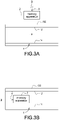
- FIG. 3A shows a schematic block diagram of burning an LED specification information according to a first embodiment of the present disclosure
- FIG. 3B which shows a schematic block diagram of burning the LED specification information according to a second embodiment of the present disclosure
- FIG. 3C shows a schematic block diagram of burning the LED specification information according to a third embodiment of the present disclosure, and also refer to FIG. 1 to FIG. 2 .
- the LED specification information Il may be turned in advance into the memory apparatus 3 (burning is indicated by dotted lines). After the burning is completed, the memory apparatus 3 is welded to the signal transmission circuit 2 and the transmission ground line 14.
- the power transmission circuit 1, the signal transmission circuit 2, and the memory apparatus 3 are packaged in a wire B to form the LED power transmission line 100. Therefore, when the LED power transmission line 100 leaves the factory, it can provide an external apparatus to identify the LED load 300 which is matched with the external apparatus.
- the memory apparatus 3 may be welded to the signal transmission circuit 2 and the transmission ground line 14, and then the power transmission circuit 1, the signal transmission circuit 2, and the memory apparatus 3 are packaged in the wire B to form the LED power transmission line 100.
- the LED specification information Il is burned in advance into the memory apparatus 3 (burning is indicated by dotted lines) through the signal transmission circuit 2. Therefore, when the LED power transmission line 100 leaves the factory, it can provide the external apparatus to identify the LED load 300 which is matched with the external apparatus.
- the memory apparatus 3 may be welded to the signal transmission circuit 2 and the transmission ground line 14, and then the power transmission circuit 1, the signal transmission circuit 2, and the memory apparatus 3 are packaged in the wire B to form the LED power transmission line 100.
- the LED specification information Il is burned in advance into the memory apparatus 3 (burning is indicated by dotted lines) through a wireless manner, such as photo coupler, Bluetooth, or Wi-Fi. Therefore, when the LED power transmission line 100 leaves the factory, it can provide the external apparatus to identify the LED load 300 which is matched with the external apparatus.
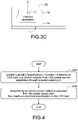
- FIG. 4 shows a flowchart of a load identification method for the LED transmission line according to present disclosure, and also refer to FIG. 1 to FIG. 3C .
- the load identification method is mainly applied to the LED power supply system A, and the LED power transmission line 100 of the LED power supply system A is coupled between any power output port 202-1 to 202-n of the LED power control apparatus 200 and the LED load 300 so that the output voltage Vo and the output current Io outputted from the power output port 202-1 to 202-n is provided to the LED load 300 through the LED power transmission line 100.
- the load identification method includes steps of: providing an LED specification information related to the LED load to the control module of the LED power control apparatus through the power output port (S120).
- the memory apparatus 3 of the LED power transmission line 100 transmits the LED specification information Il related to the LED load 300 to the control module 204 of the LED power control apparatus 200 through a transmission path between the signal transmission circuit 2 and the power output port 202-1 to 202-n so that the control module 204 controls the LED power control apparatus 200.
- the memory apparatus 3 receives the working voltage Vw provided from the control module 204 through the signal transmission circuit 2 (to work) to provide the LED specification information Il to the control module 204.
- the LED specification information Il may be burned in advance into the memory apparatus 3.
- the control module 204 controls the LED power control apparatus 200 to adjust the limitation of the output current outputted from the power output port 202-1 to 202-n from the current limit value to the rated current value so as to meet the electrical specification of the LED load 300, thereby preventing the LED load 300 from being damaged due to the excessive receiving output current (1.2 amperes) of the LED load 300.
Landscapes
- Engineering & Computer Science (AREA)
- Power Engineering (AREA)
- Circuit Arrangement For Electric Light Sources In General (AREA)
Abstract
An LED power transmission line (100) with load identification function is coupled to an LED power control apparatus (200) having a plurality of power output ports (202-1 to 202-n) and an LED load (300). The LED power transmission line (100) includes a power transmission circuit (1), a signal transmission circuit (2), and a memory apparatus (3). The power transmission circuit (1) transmits a power outputted from the power output port (202-1 to 202-n) to the LED load (300). The signal transmission circuit (2) is coupled to a control module (204) of the LED power control apparatus (200) through the power output port (202-1 to 202-n). The memory apparatus (3) stores an LED specification information (Il) related to an electrical specification of the LED load (300). The LED specification information (Il) is provided to the control module (204) through the signal transmission circuit (2) so that the control module (204) limits an output current (Io) outputted from the power output port (202-1 to 202-n) according to the LED specification information (Il).
Description
- The present disclosure relates to an LED power transmission line and a load identification method, and more particularly to an LED power transmission line with load identification function and a load identification method.
- The statements in this section merely provide background information related to the present disclosure and do not necessarily constitute prior art.
- In recent years, the development of lighting technology that uses light-emitting diodes (LEDs) as light sources has become increasingly mature, and with the improvement of LED manufacturing process and the increase in production capacity, the manufacturing cost of its hardware has also been reduced year by year. In addition, LED has the advantages of energy saving, long service life and durability, making the application of LED lighting equipment more and more widespread. In contrast, the LED lighting market has an increasing demand for LED power supply systems for supplying and controlling LED power. In general, LED lighting systems usually include LED power supply systems and LED loads (such as LED lamps) equipped with LEDs. The LED power supply system usually includes an LED power control apparatus and an LED power transmission line. The LED power control apparatus supplies power to the LED load through the LED power transmission line to make the LED load emit light and provide lighting capability.
- In order to meet the lighting requirements of different applications, various LED loads may have different current specifications. In the configuration adjustment process of the conventional LED lighting system, users usually need to purchase the corresponding LED lamps (loads), and set the output parameters of the corresponding LED power control apparatus according to the current specifications of the LED lamps. For example, the maximum output current of the LED power control apparatus is limited to supply power that meets the specifications to the LED loads. However, if the LED power control apparatus has a plurality of power output ports, the user's process of setting for each power output port is not only cumbersome to manually set, but there may be also a risk of manual setting errors or confusion or loss of the parameters that have been set for each power output port. If the LED load that does not meet the specifications is connected (for example, the current specification is less than the set value of the output current limit), it is easy to cause the LED load to burn out.
- Accordingly, the present disclosure provides an LED power transmission line with load identification function and a load identification method to save the user's effort to manually set the output current parameters by himself, and reduce the risk of errors that may be caused by the manual setting process, thereby avoiding over-current damage caused by non-compliant LED loads that are coupled to the LED power control apparatus through the LED power transmission line.
- In order to solve the above-mentioned problems, the present disclosure provides an LED power transmission line with load identification function. The LED power transmission line is coupled to an LED power control apparatus having a plurality of power output ports and an LED load. The LED power transmission line includes a power transmission circuit, a signal transmission circuit, and a memory apparatus. The power transmission circuit is coupled to any one of the power output ports and the LED load, and transmits a power outputted from the power output port to the LED load. The signal transmission circuit is coupled to a control module of the LED power control apparatus through the power output port. The memory apparatus is coupled to the signal transmission circuit, and stores an LED specification information related to the LED load. The control module acquires the LED specification information through the signal transmission circuit, and adjusts an output current outputted from the power output port according to the LED specification information.
- In order to solve the above-mentioned problems, the present disclosure provides a load identification method of an LED power transmission line. The LED power transmission line is coupled to any one power output port of an LED power control apparatus having a plurality of power output ports and an LED load. The method includes steps of: providing an LED specification information related to the LED load and stored in a memory apparatus of the LED power transmission line to the LED power control apparatus through the power output port, and providing an output current that meets an electrical specification to the LED load through the power output port.
- The main purpose and effect of the present disclosure are to couple the LED power transmission line having the memory apparatus to the control module of the LED power control apparatus and the corresponding LED load so that the control module can acquire the LED specification information, stored in the memory apparatus, corresponding to the LED load. Also, the output current outputted from the power output port is automatically limited according to the LED specification information so as to save the user's effort to manually set the output current parameters by himself, and reduce the risk of errors that may be caused by the manual setting process, thereby avoiding over-current damage caused by non-compliant LED loads that are coupled to the LED power control apparatus through the LED power transmission line.
- It is to be understood that both the foregoing general description and the following detailed description are exemplary, and are intended to provide further explanation of the present disclosure as claimed. Other advantages and features of the present disclosure will be apparent from the following description, drawings and claims.
- The present disclosure can be more fully understood by reading the following detailed description of the embodiment, with reference made to the accompanying drawing as follows:
-
FIG. 1 is a block diagram of an LED power supply system according to the present disclosure. -
FIG. 2 is a block diagram of an LED power transmission line according to the present disclosure. -
FIG. 3A is a schematic block diagram of burning an LED specification information according to a first embodiment of the present disclosure. -
FIG. 3B is a schematic block diagram of burning the LED specification information according to a second embodiment of the present disclosure. -
FIG. 3C is a schematic block diagram of burning the LED specification information according to a third embodiment of the present disclosure. -
FIG. 4 is a flowchart of a load identification method for the LED transmission line according to present disclosure. - Reference will now be made to the drawing figures to describe the present disclosure in detail. It will be understood that the drawing figures and exemplified embodiments of present disclosure are not limited to the details thereof.
- Please refer to
FIG. 1 , which shows a block diagram of an LED power supply system according to the present disclosure. The LED power supply system A includes a plurality of LEDpower transmission lines 100, an LEDpower control apparatus 200, and a plurality ofLED loads 300. The LEDpower transmission lines 100 are correspondingly coupled to a plurality of power output ports 202-1 to 202-n of the LEDpower control apparatus 200 and theLED loads 300 so that the LEDpower control apparatus 200 is coupled to theLED loads 300 through the LEDpower transmission lines 100. In particular, any one of the LEDpower transmission lines 100 may be coupled to any one of the power output ports 202-1 to 202-n to transmit an output voltage Vo and output current Io provided from the power output port 202-1 to 202-n to thecorresponding LED load 300. The LEDpower control apparatus 200 limits the sum of the output current Io outputted from the power output ports 202-1 to 202-n according to its own power supply capacity, and the user can manually adjust the output current Io outputted from each power output port 202-1 to 202-n by themselves. In particular, theLED load 300 is, for example but not limited to, a load having LED elements such as LED lamps and LED light strings. In one embodiment of the present disclosure, the type of theLED load 300 is not limited. - Please refer to
FIG. 2 , which shows a block diagram of an LED power transmission line according to the present disclosure, and also refer toFIG. 1 . The LEDpower transmission line 100 includes apower transmission circuit 1, asignal transmission circuit 2, and amemory apparatus 3. Thepower transmission circuit 1 includes atransmission bus line 12 and atransmission ground line 14. One end of thetransmission bus line 12 and one end of thetransmission ground line 14 are coupled to the power output port 202-1 to 202-n of the LEDpower control apparatus 200, and the other end of thetransmission bus line 12 and the other end of thetransmission ground line 14 are coupled to theLED load 300 to form a power-supplying loop for theLED load 300. The LEDpower control apparatus 200 includes acontrol module 204, and thecontrol module 204 controls the LEDpower control apparatus 200 to convert the input voltage Vin into the output voltage Vo so as to provide the output voltage Vo to the power output ports 202-1 to 202-n. Thecontrol module 204 may be an apparatus or a circuit that can realized logic control functions, for example but not limited to, a microcontroller (MCU), a system on a chip (Soc), or a control circuit composed of a control chip and peripheral circuits. The LEDpower transmission line 100 transmits the output voltage Vo, the output current Io outputted from the power output ports 202-1 to 202-n to theLED loads 300 through thetransmission bus line 12 for theLED loads 300 to perform light-emitting behavior, for example but not limited to, brightness change or flicking. In one embodiment, thepower transmission circuit 1 and thesignal transmission circuit 2 may be lines (wires) shown in FIGs, or they may be also circuits that simply process power or signals. - One end of the
memory apparatus 3 is coupled to thecontrol module 204 through thesignal transmission circuit 2, and the other end of thememory apparatus 3 is coupled to thetransmission ground line 14. Thememory apparatus 3 is used to store LED specification information Il related to electrical specification of theLED load 300. When the LEDpower transmission line 100 is coupled to any one of the power output ports 202-1 to 202-n, thememory apparatus 3 receives a working voltage Vw provided from thecontrol module 204 through the signal transmission circuit 2 (to work) to provide the LED specification information Il to thecontrol module 204. In particular, the working voltage Vw may be, for example but not limited to, provided by the microcontroller itself in thecontrol module 204, or provided by thecontrol module 204 with a micro battery or an external power supply. The LED specification information Il may include electrical specification of theLED load 300, such as voltage specification, current specification, power specification, or strobotac specification. In one embodiment, the LEDpower transmission line 100 is, for example but not limited to, based on current limitation specification. When thecontrol module 204 receives the LED specification information Il, thecontrol module 204 limits the output current Io outputted from the power output port 202-1 to 202-n according to the LED specification information Il to meet the electrical specification of theLED load 300, thereby avoiding damaging theLED load 300 due to the excessive receiving current of theLED load 300. In one embodiment, thememory apparatus 3 may be an apparatus with the function of storing memory data, such as a memory chip, an electrically-erasable programmable read-only memory (EEPROM), or so on. - Take the LED
power transmission line 100 coupled to the power output port 202-1 and theLED load 300, and the current specification of theLED load 300 with 0.3 amperes as an example, and it is assumed that the output current Io outputted from the power output port 202-1 is limited to a current limit value with 1.2 amperes (that is, the output current Io shall not exceed 1.2 amperes. When the LEDpower transmission line 100 coupled to theLED load 300 is coupled to the power output port 202-1 of the LEDpower control apparatus 200, thecontrol module 204 provides the working voltage to thememory apparatus 3 through thesignal transmission circuit 2 so that thememory apparatus 3 starts to work to provide the LED specification information Il to thesignal transmission circuit 2. Thecontrol module 204 receives the LED specification information Il through thesignal transmission circuit 2 to realize that the current specification of theLED load 300 is 0.3 amperes according to the LED specification information Il. Afterward, thecontrol module 204 controls the LEDpower control apparatus 200 to adjust the limitation of the output current Io of the power output port 202-1 from the default current limit value (i.e., 1.2 amperes) to a rated current value (i.e., 0.3 amperes) according to the current specification of theLED load 300 so as to meet the electrical specification of theLED load 300. Therefore, it to save the user manually sets the current output limit parameters of each power output port 202-1 to 202-n, thereby preventing theLED load 300 from being damaged due to the excessive receiving output current (1.2 amperes) of theLED load 300. - In one embodiment, the LED specification information Il provided by the
memory apparatus 3 is not only used for limiting the output current Io of the LEDpower control apparatus 200, but also depends on the characteristics of the LEDpower control apparatus 200 and theLED load 300. Specifically, thecontrol module 204 of the LEDpower control apparatus 200 receives the LED specification information Il through thesignal transmission circuit 2 to adjust the output voltage Vo and the output power outputted from the power output port 202-1 to 202-n according to the LED specification information Il. Moreover, when theLED load 300 needs to perform light-emitting behavior (for example, brightness change or flicking) and the LEDpower control apparatus 200 can also control the light-emitting behavior of theLED load 300, thecontrol module 204 adjusts the output voltage Vo of the output power outputted from the power output port 202-1 to 202-n according to the LED specification information Il to control the flicking frequency of theLED load 300. In one embodiment, thecontrol module 204 and theLED load 300 may also have a function of power line communication (PLC). When the LEDpower control apparatus 200 is coupled to theLED load 300 through the LEDpower transmission line 100, thecontrol module 204 may communicate with theLED load 300 through the LEDpower transmission line 100 to realize the output voltage Vo required by theLED load 300, and limit the output current Io outputted from the LEDpower control apparatus 200 according to the LED specification information Il. - Specifically, the memory apparatus arranged inside the LED
power transmission line 100 needs to burn in advance the LED specification information Il related to the correspondingLED load 300. In actual construction configuration of the LED lighting system, the LEDpower transmission line 100 is equipped with the LED load corresponding to the LED specification information stored in thememory apparatus 3, and is coupled to the LEDpower control apparatus 200 capable of reading data stored in thememory apparatus 3 so that the LED power control apparatus automatically adjusts the output current of each power output port 202-1 to 202-n according to the LED specification information acquired from each power output port 202-1 to 202-n. Therefore, the main purpose and effect of the present disclosure are that the user not only does not need to work hard to set the output current limit value of each power output port 202-1 to 202-n during the installation and adjustment stage of the LED lighting system, but also does not have to worry about theLED load 300 being burned by mistakenly connecting theLED load 300 that does not meet the set value after setting the parameters. For the fault repair and maintenance process of theLED load 300, the user only need to consider purchasing the same specification of theLED load 300 and directly replace it, thereby saving the effort of resetting parameters for adjustment and improving the convenience of overall system configuration and maintenance. - Please refer to
FIG. 3A , which shows a schematic block diagram of burning an LED specification information according to a first embodiment of the present disclosure,FIG. 3B , which shows a schematic block diagram of burning the LED specification information according to a second embodiment of the present disclosure,FIG. 3C , which shows a schematic block diagram of burning the LED specification information according to a third embodiment of the present disclosure, and also refer toFIG. 1 to FIG. 2 . InFIG. 3A , before the LEDpower transmission line 100 leaves the factory, the LED specification information Il may be turned in advance into the memory apparatus 3 (burning is indicated by dotted lines). After the burning is completed, thememory apparatus 3 is welded to thesignal transmission circuit 2 and thetransmission ground line 14. Finally, thepower transmission circuit 1, thesignal transmission circuit 2, and thememory apparatus 3 are packaged in a wire B to form the LEDpower transmission line 100. Therefore, when the LEDpower transmission line 100 leaves the factory, it can provide an external apparatus to identify theLED load 300 which is matched with the external apparatus. - The difference between the embodiment of the
FIG. 3B and that of theFIG. 3A is that: before the LEDpower transmission line 100 leaves the factory, thememory apparatus 3 may be welded to thesignal transmission circuit 2 and thetransmission ground line 14, and then thepower transmission circuit 1, thesignal transmission circuit 2, and thememory apparatus 3 are packaged in the wire B to form the LEDpower transmission line 100. Afterward, the LED specification information Il is burned in advance into the memory apparatus 3 (burning is indicated by dotted lines) through thesignal transmission circuit 2. Therefore, when the LEDpower transmission line 100 leaves the factory, it can provide the external apparatus to identify theLED load 300 which is matched with the external apparatus. - The difference between the embodiment of the
FIG. 3C and that of theFIG. 3A is that: before the LEDpower transmission line 100 leaves the factory, thememory apparatus 3 may be welded to thesignal transmission circuit 2 and thetransmission ground line 14, and then thepower transmission circuit 1, thesignal transmission circuit 2, and thememory apparatus 3 are packaged in the wire B to form the LEDpower transmission line 100. Afterward, the LED specification information Il is burned in advance into the memory apparatus 3 (burning is indicated by dotted lines) through a wireless manner, such as photo coupler, Bluetooth, or Wi-Fi. Therefore, when the LEDpower transmission line 100 leaves the factory, it can provide the external apparatus to identify theLED load 300 which is matched with the external apparatus. - Please refer to
FIG. 4 , which shows a flowchart of a load identification method for the LED transmission line according to present disclosure, and also refer toFIG. 1 to FIG. 3C . The load identification method is mainly applied to the LED power supply system A, and the LEDpower transmission line 100 of the LED power supply system A is coupled between any power output port 202-1 to 202-n of the LEDpower control apparatus 200 and theLED load 300 so that the output voltage Vo and the output current Io outputted from the power output port 202-1 to 202-n is provided to theLED load 300 through the LEDpower transmission line 100. The load identification method includes steps of: providing an LED specification information related to the LED load to the control module of the LED power control apparatus through the power output port (S120). Specifically, thememory apparatus 3 of the LEDpower transmission line 100 transmits the LED specification information Il related to theLED load 300 to thecontrol module 204 of the LEDpower control apparatus 200 through a transmission path between thesignal transmission circuit 2 and the power output port 202-1 to 202-n so that thecontrol module 204 controls the LEDpower control apparatus 200. Thememory apparatus 3 receives the working voltage Vw provided from thecontrol module 204 through the signal transmission circuit 2 (to work) to provide the LED specification information Il to thecontrol module 204. In particular, as shown inFIG. 3A to FIG. 3C , the LED specification information Il may be burned in advance into thememory apparatus 3. - Finally, the output current, which is outputted from the power output port, that meets the electrical specification is transmitted to the LED load (S140). Specifically, the
control module 204 controls the LEDpower control apparatus 200 to adjust the limitation of the output current outputted from the power output port 202-1 to 202-n from the current limit value to the rated current value so as to meet the electrical specification of theLED load 300, thereby preventing theLED load 300 from being damaged due to the excessive receiving output current (1.2 amperes) of theLED load 300.
Claims (10)
- An LED power transmission line (100) with load identification function coupled to an LED power control apparatus (200) having a plurality of power output ports (202-1 to 202-n) and an LED load (300), characterized in that the LED power transmission line (100) comprising:a power transmission circuit (1) coupled to any one of the power output ports (202-1 to 202-n) and the LED load (300), and configured to transmit a power outputted from the power output port (202-1 to 202-n) to the LED load (300),a signal transmission circuit (2) coupled to a control module (204) of the LED power control apparatus (200) through the power output port (202-1 to 202-n), anda memory apparatus (3) coupled to the signal transmission circuit (2), and configured to store an LED specification information (Il) related to the LED load (300),wherein the control module (204) acquires the LED specification information (Il) through the signal transmission circuit (2), and adjusts an output current (Io) outputted from the power output port (202-1 to 202-n) according to the LED specification information (Il).
- The LED power transmission line (100) as claimed in claim 1, wherein the power transmission circuit (1) comprises:a transmission bus line (12) coupled to the power output port (202-1 to 202-n) and the LED load (300), anda transmission ground line (14) coupled to the power output port (202-1 to 202-n), the LED load (300), and the memory apparatus (3),wherein the memory apparatus (3) receives a working power provided from the control module (204) to work through the signal transmission circuit (2).
- The LED power transmission line (100) as claimed in claim 1, wherein the LED specification information (Il) comprises an electrical specification; the control module (204) controls the LED power control apparatus (200) to adjust the output current (Io) according to the electrical specification from a current limit value to a rated current value that meets the electrical specification.
- The LED power transmission line (100) as claimed in claim 1, wherein the LED specification information (Il) is burned in advance in the memory apparatus (3) before the LED power transmission line (100) is packaged.
- The LED power transmission line (100) as claimed in claim 1, wherein the LED specification information (Il) is burned in the memory apparatus (3) by a wireless burning manner after the LED power transmission line (100) is packaged.
- The LED power transmission line (100) as claimed in claim 1, wherein the LED specification information (Il) is burned in the memory apparatus (3) by the signal transmission circuit (2) after the LED power transmission line (100) is packaged.
- The LED power transmission line (100) as claimed in claim 1, wherein the LED specification information (Il) comprises at least one of a voltage specification, a current specification, a power specification, and a strobotac specification of the LED load (300).
- A load identification method of an LED power transmission line (100), the LED power transmission line (100) coupled to any one power output port (202-1 to 202-n) of an LED power control apparatus (200) having a plurality of power output ports (202-1 to 202-n) and an LED load (300), characterized in that the method comprising steps of:providing an LED specification information (Il) related to the LED load (300) and stored in a memory apparatus (3) of the LED power transmission line (100) to the LED power control apparatus (200) through the power output port (202-1 to 202-n), andproviding an output current (Io) that meets an electrical specification to the LED load (300) through the power output port (202-1 to 202-n).
- The load identification method as claimed in claim 8, further comprising a step of:
providing a working power to the memory apparatus (3) by the LED power control apparatus (200) so that the memory apparatus (3) works to provide the LED specification information (Il). - The load identification method as claimed in claim 8, further comprising a step of:
burning in advance the LED specification information (Il) in the memory apparatus (3).
Applications Claiming Priority (1)
| Application Number | Priority Date | Filing Date | Title |
|---|---|---|---|
| CN202110430048.6A CN115224677A (en) | 2021-04-21 | 2021-04-21 | LED power transmission line with load identification function and load identification method thereof |
Publications (1)
| Publication Number | Publication Date |
|---|---|
| EP4080993A1 true EP4080993A1 (en) | 2022-10-26 |
Family
ID=76920500
Family Applications (1)
| Application Number | Title | Priority Date | Filing Date |
|---|---|---|---|
| EP21184098.8A Pending EP4080993A1 (en) | 2021-04-21 | 2021-07-06 | Led power transmission line with load identification function and load identification method |
Country Status (3)
| Country | Link |
|---|---|
| US (1) | US11582848B2 (en) |
| EP (1) | EP4080993A1 (en) |
| CN (1) | CN115224677A (en) |
Citations (1)
| Publication number | Priority date | Publication date | Assignee | Title |
|---|---|---|---|---|
| US20120119661A1 (en) * | 2009-11-25 | 2012-05-17 | Delo Industrial Adhesives Llc | Light emitting diode operating device and method |
Family Cites Families (9)
| Publication number | Priority date | Publication date | Assignee | Title |
|---|---|---|---|---|
| CN101835301A (en) * | 2009-03-11 | 2010-09-15 | 上海创波光电科技有限公司 | Method for automatically identifying LED load light source by using memory chip and implementation device |
| TWI430706B (en) * | 2009-11-10 | 2014-03-11 | Upec Electronics Corp | Lamps and lanterns and lamps |
| CN102103386B (en) * | 2009-12-22 | 2013-06-19 | 宏碁股份有限公司 | Voltage adjustment circuit, voltage adjustment method and computer system thereof |
| KR20140094674A (en) * | 2014-06-30 | 2014-07-30 | 최창준 | DC Power Line Communication Control System |
| US10320382B2 (en) * | 2016-04-15 | 2019-06-11 | Voyomotive, Llc | Power line communication smart relay |
| KR102475304B1 (en) * | 2016-06-03 | 2022-12-07 | 삼성전자 주식회사 | Electronic device and cable and operation method thereof |
| CN106028554A (en) * | 2016-06-30 | 2016-10-12 | 浙江大邦科技有限公司 | LED driver, and controller and control method thereof |
| CN106686809B (en) * | 2016-11-28 | 2018-11-16 | 深圳市镭润科技有限公司 | A kind of adaptive LED light adjusting circuit and method |
| CN107949112A (en) * | 2017-12-04 | 2018-04-20 | 道县胜锋电子科技有限公司 | High efficiency smart tune stream lightens the outer lighting system of LED indoor |
-
2021
- 2021-04-21 CN CN202110430048.6A patent/CN115224677A/en active Pending
- 2021-07-06 EP EP21184098.8A patent/EP4080993A1/en active Pending
- 2021-07-08 US US17/370,525 patent/US11582848B2/en active Active
Patent Citations (1)
| Publication number | Priority date | Publication date | Assignee | Title |
|---|---|---|---|---|
| US20120119661A1 (en) * | 2009-11-25 | 2012-05-17 | Delo Industrial Adhesives Llc | Light emitting diode operating device and method |
Also Published As
| Publication number | Publication date |
|---|---|
| CN115224677A (en) | 2022-10-21 |
| US20220346203A1 (en) | 2022-10-27 |
| US11582848B2 (en) | 2023-02-14 |
Similar Documents
| Publication | Publication Date | Title |
|---|---|---|
| US10620675B2 (en) | Intelligent power distribution system and method | |
| US11725808B2 (en) | Carry-signal controlled LED light with low power consumption and LED light string having the same | |
| CN110460449B (en) | Repeater and power supply method | |
| US11582848B2 (en) | LED power transmission line with load identification function and load identification method | |
| CN112526278A (en) | Switching device for optical module aging test, optical module aging device and method | |
| TWI771992B (en) | Led power transmission line with load identification function and method of identification the same | |
| CN112423433A (en) | LED driving power supply, control method thereof, lamp and computer readable storage medium | |
| CN111628875A (en) | Ethernet power supply equipment port power supply state indicating circuit and power supply equipment | |
| CN110708263A (en) | Switch | |
| CN115566781A (en) | Intelligent emergency power supply system | |
| US10897284B2 (en) | System and method for programmably operating DC loads | |
| WO2019057210A1 (en) | Power supply applied to multiple paths of loads, integrated power supply and illumination lamp | |
| CN116685027B (en) | On-off control circuit, lighting system and on-off control method | |
| CN114665522A (en) | Multi-power Ethernet power supply system and control device thereof | |
| EP4142433B1 (en) | Straight tube light emitting diode lamp | |
| US20240258814A1 (en) | Distributive fast charging device and charging system | |
| US8775789B2 (en) | Multi-mode data card and calibrating method thereof | |
| CN222812924U (en) | A quantity detection device and a lamp | |
| US20260128915A1 (en) | Ethernet power source equipment, step-down control circuit, and method of controlling the same | |
| CN215897312U (en) | Charging equipment control system based on automatic switching output current | |
| CN219392499U (en) | Electronic table card management and control equipment control circuit and electronic table card management and control equipment | |
| CN213948270U (en) | Car taillight control device | |
| US20240405575A1 (en) | Fast charging system, one to many fast charging data cable, and charging management device | |
| CN219577329U (en) | Constant voltage power supply of intelligent gateway | |
| CN220511288U (en) | LED breakpoint continuous transmission module |
Legal Events
| Date | Code | Title | Description |
|---|---|---|---|
| PUAI | Public reference made under article 153(3) epc to a published international application that has entered the european phase |
Free format text: ORIGINAL CODE: 0009012 |
|
| STAA | Information on the status of an ep patent application or granted ep patent |
Free format text: STATUS: REQUEST FOR EXAMINATION WAS MADE |
|
| 17P | Request for examination filed |
Effective date: 20220630 |
|
| AK | Designated contracting states |
Kind code of ref document: A1 Designated state(s): AL AT BE BG CH CY CZ DE DK EE ES FI FR GB GR HR HU IE IS IT LI LT LU LV MC MK MT NL NO PL PT RO RS SE SI SK SM TR |
|
| STAA | Information on the status of an ep patent application or granted ep patent |
Free format text: STATUS: EXAMINATION IS IN PROGRESS |
|
| 17Q | First examination report despatched |
Effective date: 20231018 |