EP4080659A1 - Battery module, and battery pack and automobile including same - Google Patents
Battery module, and battery pack and automobile including same Download PDFInfo
- Publication number
- EP4080659A1 EP4080659A1 EP21862080.5A EP21862080A EP4080659A1 EP 4080659 A1 EP4080659 A1 EP 4080659A1 EP 21862080 A EP21862080 A EP 21862080A EP 4080659 A1 EP4080659 A1 EP 4080659A1
- Authority
- EP
- European Patent Office
- Prior art keywords
- partition
- battery
- leak prevention
- battery module
- pipe
- Prior art date
- Legal status (The legal status is an assumption and is not a legal conclusion. Google has not performed a legal analysis and makes no representation as to the accuracy of the status listed.)
- Granted
Links
Images


Classifications
-
- H—ELECTRICITY
- H01—ELECTRIC ELEMENTS
- H01M—PROCESSES OR MEANS, e.g. BATTERIES, FOR THE DIRECT CONVERSION OF CHEMICAL ENERGY INTO ELECTRICAL ENERGY
- H01M50/00—Constructional details or processes of manufacture of the non-active parts of electrochemical cells other than fuel cells, e.g. hybrid cells
- H01M50/30—Arrangements for facilitating escape of gases
-
- H—ELECTRICITY
- H01—ELECTRIC ELEMENTS
- H01M—PROCESSES OR MEANS, e.g. BATTERIES, FOR THE DIRECT CONVERSION OF CHEMICAL ENERGY INTO ELECTRICAL ENERGY
- H01M50/00—Constructional details or processes of manufacture of the non-active parts of electrochemical cells other than fuel cells, e.g. hybrid cells
- H01M50/20—Mountings; Secondary casings or frames; Racks, modules or packs; Suspension devices; Shock absorbers; Transport or carrying devices; Holders
- H01M50/204—Racks, modules or packs for multiple batteries or multiple cells
-
- H—ELECTRICITY
- H01—ELECTRIC ELEMENTS
- H01M—PROCESSES OR MEANS, e.g. BATTERIES, FOR THE DIRECT CONVERSION OF CHEMICAL ENERGY INTO ELECTRICAL ENERGY
- H01M10/00—Secondary cells; Manufacture thereof
- H01M10/60—Heating or cooling; Temperature control
- H01M10/62—Heating or cooling; Temperature control specially adapted for specific applications
- H01M10/625—Vehicles
-
- H—ELECTRICITY
- H01—ELECTRIC ELEMENTS
- H01M—PROCESSES OR MEANS, e.g. BATTERIES, FOR THE DIRECT CONVERSION OF CHEMICAL ENERGY INTO ELECTRICAL ENERGY
- H01M50/00—Constructional details or processes of manufacture of the non-active parts of electrochemical cells other than fuel cells, e.g. hybrid cells
- H01M50/20—Mountings; Secondary casings or frames; Racks, modules or packs; Suspension devices; Shock absorbers; Transport or carrying devices; Holders
- H01M50/249—Mountings; Secondary casings or frames; Racks, modules or packs; Suspension devices; Shock absorbers; Transport or carrying devices; Holders specially adapted for aircraft or vehicles, e.g. cars or trains
-
- H—ELECTRICITY
- H01—ELECTRIC ELEMENTS
- H01M—PROCESSES OR MEANS, e.g. BATTERIES, FOR THE DIRECT CONVERSION OF CHEMICAL ENERGY INTO ELECTRICAL ENERGY
- H01M50/00—Constructional details or processes of manufacture of the non-active parts of electrochemical cells other than fuel cells, e.g. hybrid cells
- H01M50/20—Mountings; Secondary casings or frames; Racks, modules or packs; Suspension devices; Shock absorbers; Transport or carrying devices; Holders
- H01M50/271—Lids or covers for the racks or secondary casings
-
- H—ELECTRICITY
- H01—ELECTRIC ELEMENTS
- H01M—PROCESSES OR MEANS, e.g. BATTERIES, FOR THE DIRECT CONVERSION OF CHEMICAL ENERGY INTO ELECTRICAL ENERGY
- H01M50/00—Constructional details or processes of manufacture of the non-active parts of electrochemical cells other than fuel cells, e.g. hybrid cells
- H01M50/30—Arrangements for facilitating escape of gases
- H01M50/35—Gas exhaust passages comprising elongated, tortuous or labyrinth-shaped exhaust passages
- H01M50/358—External gas exhaust passages located on the battery cover or case
-
- H—ELECTRICITY
- H01—ELECTRIC ELEMENTS
- H01M—PROCESSES OR MEANS, e.g. BATTERIES, FOR THE DIRECT CONVERSION OF CHEMICAL ENERGY INTO ELECTRICAL ENERGY
- H01M50/00—Constructional details or processes of manufacture of the non-active parts of electrochemical cells other than fuel cells, e.g. hybrid cells
- H01M50/30—Arrangements for facilitating escape of gases
- H01M50/383—Flame arresting or ignition-preventing means
-
- H—ELECTRICITY
- H01—ELECTRIC ELEMENTS
- H01M—PROCESSES OR MEANS, e.g. BATTERIES, FOR THE DIRECT CONVERSION OF CHEMICAL ENERGY INTO ELECTRICAL ENERGY
- H01M50/00—Constructional details or processes of manufacture of the non-active parts of electrochemical cells other than fuel cells, e.g. hybrid cells
- H01M50/30—Arrangements for facilitating escape of gases
- H01M50/394—Gas-pervious parts or elements
-
- H—ELECTRICITY
- H01—ELECTRIC ELEMENTS
- H01M—PROCESSES OR MEANS, e.g. BATTERIES, FOR THE DIRECT CONVERSION OF CHEMICAL ENERGY INTO ELECTRICAL ENERGY
- H01M2200/00—Safety devices for primary or secondary batteries
- H01M2200/20—Pressure-sensitive devices
-
- H—ELECTRICITY
- H01—ELECTRIC ELEMENTS
- H01M—PROCESSES OR MEANS, e.g. BATTERIES, FOR THE DIRECT CONVERSION OF CHEMICAL ENERGY INTO ELECTRICAL ENERGY
- H01M2220/00—Batteries for particular applications
- H01M2220/20—Batteries in motive systems, e.g. vehicle, ship, plane
-
- Y—GENERAL TAGGING OF NEW TECHNOLOGICAL DEVELOPMENTS; GENERAL TAGGING OF CROSS-SECTIONAL TECHNOLOGIES SPANNING OVER SEVERAL SECTIONS OF THE IPC; TECHNICAL SUBJECTS COVERED BY FORMER USPC CROSS-REFERENCE ART COLLECTIONS [XRACs] AND DIGESTS
- Y02—TECHNOLOGIES OR APPLICATIONS FOR MITIGATION OR ADAPTATION AGAINST CLIMATE CHANGE
- Y02E—REDUCTION OF GREENHOUSE GAS [GHG] EMISSIONS, RELATED TO ENERGY GENERATION, TRANSMISSION OR DISTRIBUTION
- Y02E60/00—Enabling technologies; Technologies with a potential or indirect contribution to GHG emissions mitigation
- Y02E60/10—Energy storage using batteries
Definitions
- the present disclosure relates to a battery module, and a battery pack and a vehicle including the same.
- Secondary batteries which are highly applicable to various products and exhibit superior electrical properties such as high energy density, etc. are commonly used not only in portable devices but also in electric vehicles (EVs) or hybrid electric vehicles (HEVs) driven by electrical power sources.
- EVs electric vehicles
- HEVs hybrid electric vehicles
- the secondary battery is drawing attentions as a new energy source for enhancing environment friendliness and energy efficiency in that the use of fossil fuels can be reduced greatly and no byproduct is generated during energy consumption.
- Secondary batteries widely used at the preset include lithium ion batteries, lithium polymer batteries, nickel cadmium batteries, nickel hydrogen batteries, nickel zinc batteries and the like.
- An operating voltage of the unit secondary battery cell namely a unit battery cell, is about 2.5V to 4.5V. Therefore, if a higher output voltage is required, a plurality of battery cells may be connected in series to configure a battery pack. In addition, depending on the charge/discharge capacity required for the battery pack, a plurality of battery cells may be connected in parallel to configure a battery pack. Thus, the number of battery cells included in the battery pack may be variously set according to the required output voltage or the demanded charge/discharge capacity.
- the battery module is necessary to exhaust only the gas without expelling the flame out of the module case for safety.
- the conventional battery module generally does not include a structure for discharging only the exhaust gas while preventing flame leak when a fire situation occurs due to thermal runaway of the battery cells.
- the present disclosure is directed to providing a battery module, which may prevent a flame leak to the outside of a module case and also discharge an exhaust gas out of the module case when a fire situation occurs due to thermal runaway of battery cells, and a battery pack and a vehicle including the battery module.
- a battery module comprising: at least one battery cell assembly including at least one battery cell; a module case configured to accommodate the at least one battery cell assembly; and an exhaust housing coupled to the module case to cover the at least one battery cell assembly, the exhaust housing having at least one gas discharge hole for discharging a gas inside the module case and at least one flame leak prevention partition for variably adjusting a length thereof.
- the at least one flame leak prevention partition may have a length variable along a width direction of the module case according to a user manipulation.
- the at least one flame leak prevention partition may be provided to perform multi-stage sliding along the width direction.
- the exhaust housing may include a housing base configured to cover an upper side of the module case; the at least one flame leak prevention partition fixed to the housing base; a pipe unit fixed on the at least one flame leak prevention partition and configured to communicate with the module case and the at least one gas discharge hole; and a housing cover configured to cover the pipe unit and coupled to the housing base.
- the housing base may have at least one partition insert groove into which the at least one flame leak prevention partition is inserted.
- the at least one flame leak prevention partition may be configured to variably perform multi-stage sliding along a width direction of the housing base.
- the pipe unit may include a plurality of pipe connectors coupled to the housing cover and the housing base; and a plurality of pipe cylinders configured to communicate with the plurality of pipe connectors and fixed on the at least one flame leak prevention partition.
- Each of the plurality of pipe cylinders may include a plurality of cylinder tubes having a predetermined length and coupled to the plurality of pipe connectors; and at least one cylinder grid configured to connect the plurality of cylinder tubes to each other.
- the present disclosure provides a battery pack, comprising: at least one battery module according to the above embodiments; and a pack case configured to package the at least one battery module.
- the present disclosure provides a vehicle, comprising at least one battery pack according to the above embodiment.
- a battery module which may prevent a flame leak to the outside of a module case and also discharge an exhaust gas out of the module case when a fire situation occurs due to thermal runaway of battery cells, and a battery pack and a vehicle including the battery module.
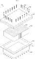
- FIG. 1 is a diagram for illustrating a battery module according to an embodiment of the present disclosure
- FIG. 2 is an exploded perspective view showing the battery module of FIG. 1 .
- the battery module 10 may include a battery cell assembly 100, a module case 200, a fastening member 300, and an exhaust housing 400.
- At least one battery cell assembly 100 or a plurality of battery cell assemblies 100 may be provided.
- the battery cell assembly 100 may include one or more battery cells 150.
- the battery cell assembly 100 includes a plurality of battery cells 150.
- the plurality of battery cells 150 are secondary batteries, and may be provided as pouch-type secondary batteries, rectangular secondary batteries or a cylindrical secondary batteries. Hereinafter, in this embodiment, it will be described that the plurality of battery cells 150 are pouch-type secondary batteries.
- the module case 200 may accommodate the at least one battery cell assembly 100. To this end, an accommodation space for accommodating the at least one battery cell assembly 100 may be provided in the module case 200.
- the module case 200 may have a plurality of fastening holes 250 for coupling with the exhaust housing 400, explained later.
- the plurality of fastening holes 250 may be provided to be spaced apart from each other by a predetermined distance along an edge of the module case 200.
- the fastening member 300 may connect the module case 200 and the exhaust housing 400, explained later, to each other.
- the fastening member 300 may be provided in plural.
- the plurality of fastening members 300 may include a plurality of fastening bolts 302 and a plurality of fastening nuts 304.
- the plurality of fastening bolts 302 may pass through the exhaust housing 400, explained later, and the fastening holes 250 of the module case 200 and be fastened with the fastening nuts 304, respectively.
- the exhaust housing 400 may prevent flame generated by the fire from being discharged to the outside of the module case 200 and discharge a gas out of the module case 200. Since the battery module 10 according to this embodiment may discharge only the gas to the outside through the exhaust housing 400 while suppressing the flame emission when the fire situation occurs, it is possible to prevent a greater damage from being caused by the fire situation in advance.
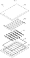
- FIG. 3 is an exploded perspective view showing the exhaust housing of the battery module of FIG. 2 .
- the exhaust housing 400 is coupled to the module case 200 (see FIG. 2 ) to cover the at least one battery cell assembly 100 (see FIG. 2 ). Also, the exhaust housing 400 may include at least one gas discharge hole 416 for discharging the gas inside the module case 200, and at least one flame leak prevention partition 430 capable of variably adjusting the length thereof.
- FIG. 4 is a diagram for illustrating a housing base of the exhaust housing of FIG. 3 .
- the housing base 410 may cover an upper side of the module case 200 (see FIG. 2 ).
- the housing base 410 may include a case fastening hole 412, a partition insert groove 414, the gas discharge hole 416, and a sealing member insert groove 418.
- the case fastening hole 412 may be provided in plural, and the plurality of case fastening holes 412 may be arranged to be spaced apart from each other by a predetermined distance along the edge of the housing base 410.
- the fastening bolts 302 of the fastening member 300 may penetrate the plurality of case fastening holes 412.
- the partition insert groove 414 is provided on an upper side of the bottom of the housing base 410, and may be formed in a predetermined length along the width direction of the housing base 410.
- the flame leak prevention partition 430 explained later, may be inserted into the partition insert groove 414.
- the partition insert groove 414 may be provided in plural.
- the plurality of partitions insert grooves 414 may be disposed to be spaced apart from each other by a predetermined distance along the length direction of the housing base 410.
- the gas discharge hole 416 may be provided in the bottom of the housing base 410.
- the gas discharge hole 416 may be provided to communicate with the inside of the module case 200 (see FIG. 2 ).
- the gas discharge hole 416 may be provided in plural.
- the plurality of gas discharge holes 416 may be provided near both edges of the bottom of the housing base 410.
- the sealing member insert groove 418 may be provided at an edge of the upper surface of the housing base 410.
- the sealing member insert groove 418 may be provided between the plurality of case fastening holes 412 and the partition insert groove 414.
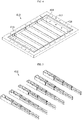
- FIG. 5 is a diagram for illustrating a flame leak prevention partition of the exhaust housing of FIG. 3
- FIGS. 6 and 7 are diagrams for illustrating a sliding operation of the flame leak prevention partition of FIG. 5 .
- the flame leak prevention partition 430 may be provided in plural.
- the plurality of flame leak prevention partitions 430 may secure a predetermined rigidity while acting as a bead, thereby securing rigidity to suppress the explosive force when a fire situation occurs.
- the plurality of flame leak prevention partitions 430 have a predetermined height, and serve as the beads when a fire situation occurs to minimize flame propagation to the surrounding area.
- the flame leak prevention partition 430 may be provided to have a length variable along the width direction of the module case 200 (see FIG. 2 ) according to a user manipulation. Specifically, the flame leak prevention partition 430 may be provided to perform multi-stage sliding along the width direction. More specifically, the flame leak prevention partition 430 may be provided to variably perform multi-stage sliding along the width direction of the housing base 410.
- the flame leak prevention partition 430 may be fixed to the housing base 410. Specifically, the flame leak prevention partition 430 may be inserted into and mounted to the partition insert groove 414 of the housing base 410.
- the flame leak prevention partition 430 may include a plurality of partitions 431, 433, 435, 437 for the multi-stage sliding.
- the plurality of partitions 431, 433, 435, and 437 may include a first partition 431, a second partition 433, a third partition 435, and a fourth partition 437.
- the first partition 431 When mounted to the housing base 410, the first partition 431 may be disposed at one end of the housing base 410 in the width direction.
- a plurality of pipe storage boxes 432 may be formed at an upper side of the first partition 431.
- a pipe cylinder 455 of a pipe unit 450, explained later, may be fixed to the plurality of pipe storage boxes 432.
- the first partition 431 may have a sliding groove 4312 for guiding the sliding of the second partition 433, explained later.
- the sliding groove 4312 is provided at both sides of the inner surface of the first partition 431, and may guide variable sliding of the second partition 433, explained later, along the width direction of the housing base 410.
- the second partition 433 may be mounted to the first partition 431 to be slidable from the first partition 431.
- the plurality of pipe storage boxes 434 may be formed at an upper side of the second partition 433.
- the pipe cylinder 455 of the pipe unit 450 explained later, may be fixed to the plurality of pipe storage boxes 434.
- the second partition 433 may include a sliding groove 4332 and a sliding protrusion 4335.
- the sliding groove 4332 may guide the sliding of the third partition 435, explained later.
- the sliding groove 4332 is provided at both sides of the inner surface of the second partition 433, and may guide variable sliding of the third partition 435, explained later, along the width direction of the housing base 410.
- the sliding protrusion 4335 may be provided at both sides of the outer surface of the second partition 433.
- the sliding protrusion 4335 of the second partition 433 may be slidably mounted to the sliding groove 4312 of the first partition 431.
- the third partition 435 may be mounted to the second partition 433 to be slidable from the second partition 433.
- a plurality of pipe storage boxes 436 may be formed at an upper side of the third partition 435.
- a pipe cylinder 455 of a pipe unit 450, explained later, may be fixed to the plurality of pipe storage boxes 436.
- the third partition 435 may include a sliding groove 4352 and a sliding protrusion 4355.
- the sliding groove 4352 may guide the sliding of the fourth partition 437, explained later.
- the sliding groove 4352 is provided at both sides of the inner surface of the third partition 435, and may guide variable sliding of the fourth partition 437, explained later, along the width direction of the housing base 410.
- the sliding protrusion 4355 may be provided at both sides of the outer surface of the third partition 435.
- the sliding protrusion 4355 of the third partition 435 may be slidably mounted to the sliding groove 4332 of the second partition 433.
- the fourth partition 437 may be mounted to the third partition 435 to be slidable from the third partition 435.
- At least one pipe storage box 438 may be formed at an upper side of the fourth partition 437.
- a pipe cylinder 455 of a pipe unit 450, explained later, may be fixed to the at least one pipe storage box 438.
- the fourth partition 437 may include a sliding protrusion 4375.
- the sliding protrusion 4375 may be provided at both sides of the outer surface of the fourth partition 437.
- the sliding protrusion 4375 of the fourth partition 437 may be slidably mounted to the sliding groove 4352 of the third partition 435.
- the sliding operation of the first partition 431 to the fourth partition 437 will be described as follows.
- the fourth partition 437 may be inserted into the third partition 435 by sliding toward the third partition 435 through a user manipulation or the like.
- a three-stage partition structure of the first partition 431 to the third partition 435 may be formed.
- the third partition 435 may be inserted into the second partition 433 by sliding toward the second partition 433 through a user manipulation or the like.
- a two-stage partition structure of the first partition 431 and the second partition 433 may be formed.
- the second partition 433 may be inserted into the first partition 431 by sliding toward the first partition 431 through a user manipulation or the like.
- a one-stage partition structure in which the second to fourth partitions 433 to 437 are accommodated in the first partition 431 may be formed.
- the flame leak prevention partition 430 may form a partition structure of four stages in total of, from 1 stage to 4 stage, through the multi-stage sliding structure, and thus the length of the flame leak prevention partition 430 may be variably adjusted.
- the flame leak prevention partition 430 may be installed in a customized form, so the module compatibility of the exhaust housing 400 may be increased.
- FIG. 8 is a diagram for illustrating a pipe unit of the exhaust housing of FIG. 3
- FIG. 9 is a diagram for illustrating a pipe connector of the pipe unit of FIG. 8
- FIGS. 10 and 11 are diagrams for illustrating a connection between the pipe connector of FIG. 9 and a pipe cylinder
- FIG. 12 is a diagram for illustrating the pipe cylinder of the pipe unit of FIG. 8
- FIG. 13 is an exploded perspective view showing the pipe cylinder of FIG. 12
- FIG. 14 is a sectional view showing the pipe cylinder of FIG. 13 .
- the pipe unit 450 may be fixed on the at least one flame leak prevention partition 430 and communicate with the module case 200 and the at least one gas discharge hole 416.
- the pipe unit 450 may include a plurality of pipe connectors 451 and a plurality of pipe cylinders 455.
- the plurality of pipe connectors 451 may be coupled to a housing cover 490, explained later, and the housing base 410. Specifically, the plurality of pipe connectors 451 may be disposed at the upper side of the plurality of gas discharge holes 416 of the housing base 410.
- Each of the plurality of pipe connectors 451 may include a gas discharge hole connection portion 452, an exhaust hole connection portion 453 and a cylinder connection portion 454.
- the gas discharge hole connection portion 452 may be provided at a lower side of the pipe connector 451 and be mounted in communication with the plurality of gas discharge holes 416 of the housing base 410.
- the gas discharge hole connection portion 452 may guide the gas inside the module case 200 to the inside of the pipe connector 451.
- gas discharge hole connection portions 452 other than at least one gas discharge hole connection portion 452 among the plurality of pipe connectors 451 may be sealed using a packing member P.
- the packing member P may be made of a rubber material or the like, and the gas discharge hole connection portion 452 may be inserted therein to seal the hole or the like of the gas discharge hole connection portion 452.
- the exhaust hole connection portion 453 may be provided at an upper side of the pipe connector 451 and be provided at a side opposite to the gas discharge hole connection portion 452. Among the plurality of pipe connectors 451, at least one exhaust hole connection portion 453 may be mounted in communication with an exhaust hole 495 of the housing cover 490, explained later.
- exhaust hole connection portions 453 other than at least one exhaust hole connection portion 453 among the plurality of pipe connectors 451 may be sealed using the packing member P.
- the cylinder connection portion 454 may be provided in a pair.
- the pair of cylinder connection portions 454 may be connected to communicate with one or more cylinder tubes 457 of the pipe cylinder 455, explained later, according to the preset intake and exhaust directions of the gas.
- a cylinder connection portion 454 that is not connected to the cylinder tube 457, explained later, may be sealed using the packing member P.
- the plurality of pipe cylinders 455 may communicate with the plurality of pipe connectors 451 and be fixed on the at least one flame leak prevention partition 430. Specifically, the plurality of pipe cylinders 455 may be connected in communication with the cylinder connection portion 454.
- the plurality of pipe cylinders 455 may include a plurality of cylinder tubes 457 and at least one cylinder grid 459.
- the plurality of cylinder tubes 457 are formed in a predetermined length, and may be coupled with the plurality of pipe connectors 451. Specifically, the plurality of cylinder tubes 457 may be connected in communication with the cylinder connection portion 454.
- the at least one cylinder grid 459 is for connecting the plurality of cylinder tubes 457 to each other, and may be mounted between two facing cylinder tubes 457.
- the at least one cylinder grid 459 has a sectional structure of a grid shape, and may connect two cylinder tubes 457 to each other. In addition, the at least one cylinder grid 459 may function as a guide for preventing flame leak.
- the sealing member 470 (see FIG. 3 ) is for sealing the inside of the exhaust housing 400, and may be inserted into and mounted to the sealing member insert groove 418 of the housing base 410.
- FIG. 15 is a diagram for illustrating a housing cover of the exhaust housing of FIG. 3 .
- the housing cover 490 covers the pipe unit 450 and may be coupled with the housing base 410.
- the housing cover 490 may include a case fastening hole 492 and an exhaust hole 495.
- the case fastening hole 492 may be provided in plural.
- the plurality of case fastening holes 492 are formed along the edge of the housing cover 490 and may be spaced apart from each other by a predetermined distance.
- the fastening bolts 302 of the fastening member 300 may penetrate the plurality of case fastening holes 492.
- the exhaust hole 495 is formed at an upper side of the housing cover 410, and may be connected in communication with the exhaust hole connection portion 453 (see FIG. 9 ) of the pipe connector 451 (see FIG. 9 ) of the pipe unit 450.
- the gas flowing along the pipe unit 450 may be discharged out of the exhaust housing 400 through the exhaust hole 495.
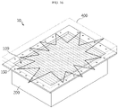
- FIGS. 16 to 18 are diagrams for illustrating gas discharge when a fire occurs due to a fire situation of the battery module of FIG. 1 .
- a fire may occur in at least one battery cell 150.
- a fire occurs as above, in order to prevent a larger secondary damage, it is necessary to emit only gas out of the module case 200 while preventing the leakage of flame or the like out of the module case 200.
- the gas G generated inside the module case 200 may flow along a exhaust path (indicated by a dotted line in FIG. 17 ) of the pipe unit 450 of the exhaust housing 400 and then be quickly discharged out of the module case 200 through the exhaust hole 495 (see FIG. 18 ) of the housing cover 490.
- the battery module 10 may discharge the gas G out of the module case 200 more quickly while suppressing the emission of the flame by means of the exhaust housing 400 when the fire situation occurs, thereby minimizing a secondary damage that may be caused by the fire.
- FIGS. 19 to 21 are diagrams for illustrating exhaust housings according to various embodiments of the present disclosure.
- the battery module 20 when the explosive force is small, for example, when the capacity of the battery cells is relatively small, the explosion may be suppressed even with low rigidity, so a manufacturer or the like may reduce the number of flame leak prevention partitions 530 in the exhaust housing 500. Accordingly, the battery module 20 according to this embodiment may secure cost competitiveness by reducing costs as much as the reduced number of the flame leak prevention partitions 430.
- the manufacturer or the like may further increase the number of flame leak prevention partitions 630 in the exhaust housing 600.
- the manufacturer or the like may reduce the length of the flame leak prevention partition 730 of the exhaust housing 700. That is, the flame leak prevention partition 730 may be modified to a three-stage partition type. This is only an example, and it is also possible to modify the flame leak prevention partition 730 to a two-stage or one-stage partition type, and it is also possible to increase the number of partitions to five or more according to the design or the like.
- the number of flame leak prevention partitions 430, 530, 630, 730 of the exhaust housings 400, 500, 600, 700 may be reduced according to the width size or rigidity of the battery module 10, 20, 30, 40, or the length thereof may be varied. Accordingly, it is possible to implement an exhaust housing structure with high extensibility and compatibility.
- FIG. 22 is a diagram for illustrating a battery pack according to an embodiment of the present disclosure
- FIG. 23 is a diagram for illustrating a vehicle according to an embodiment of the present disclosure.
- a battery pack 1 may include at least one battery module 10 according to the former embodiment and a pack case 50 for packaging the at least one battery module 10. Moreover, in addition to the battery module 10, the battery modules 20 to 40 of the former embodiments may also be included.
- the battery pack 1 may be provided to a vehicle as a fuel source of a vehicle V.
- the battery pack 1 may be provided to an electric vehicle, a hybrid electric vehicle, and various other-type vehicles V capable of using the battery pack 1 as a fuel source.
- the battery pack 1 may be provided in other devices, instruments or facilities such as an energy storage system using a secondary battery, in addition to the vehicle V.
- the battery pack 1 of this embodiment and devices, instruments or facilities such as a vehicle, which have the battery pack 1, include the battery module 10 to 40 as described above, and thus it is possible to implement a battery pack 1 having all the advantages of the battery module 10 to 40 described above, or devices, instruments, facilities or the like such as a vehicle V, which have the battery pack 1.
- a battery module 10, 20, 30, 40 which may prevent a flame leak to the outside of a module case 200 and also discharge an exhaust gas G out of the module case 200 when a fire situation occurs due to thermal runaway of battery cells 100, and a battery pack 1 and a vehicle V including the battery module 10, 20, 30, 40.
Landscapes
- Chemical & Material Sciences (AREA)
- Chemical Kinetics & Catalysis (AREA)
- Electrochemistry (AREA)
- General Chemical & Material Sciences (AREA)
- Engineering & Computer Science (AREA)
- Aviation & Aerospace Engineering (AREA)
- Manufacturing & Machinery (AREA)
- Battery Mounting, Suspending (AREA)
- Gas Exhaust Devices For Batteries (AREA)
Abstract
Description
- The present disclosure relates to a battery module, and a battery pack and a vehicle including the same.
- The present application claims priority to
Korean Patent Application No. 10-2020-0108075 filed on August 26, 2020 - Secondary batteries which are highly applicable to various products and exhibit superior electrical properties such as high energy density, etc. are commonly used not only in portable devices but also in electric vehicles (EVs) or hybrid electric vehicles (HEVs) driven by electrical power sources. The secondary battery is drawing attentions as a new energy source for enhancing environment friendliness and energy efficiency in that the use of fossil fuels can be reduced greatly and no byproduct is generated during energy consumption.
- Secondary batteries widely used at the preset include lithium ion batteries, lithium polymer batteries, nickel cadmium batteries, nickel hydrogen batteries, nickel zinc batteries and the like. An operating voltage of the unit secondary battery cell, namely a unit battery cell, is about 2.5V to 4.5V. Therefore, if a higher output voltage is required, a plurality of battery cells may be connected in series to configure a battery pack. In addition, depending on the charge/discharge capacity required for the battery pack, a plurality of battery cells may be connected in parallel to configure a battery pack. Thus, the number of battery cells included in the battery pack may be variously set according to the required output voltage or the demanded charge/discharge capacity.
- Meanwhile, when a plurality of battery cells are connected in series or in parallel to configure a battery pack, it is common to configure a battery module composed of at least one battery cell first, and then configure a battery pack by using at least one battery module and adding other components.
- If a fire occurs in battery cells inside a module case that accommodates the battery cells, the battery module is necessary to exhaust only the gas without expelling the flame out of the module case for safety.
- However, the conventional battery module generally does not include a structure for discharging only the exhaust gas while preventing flame leak when a fire situation occurs due to thermal runaway of the battery cells.
- Therefore, when a fire situation occurs due to the thermal runaway of the battery cells, it is demanded to find a way to prevent flame leak to the outside of the module case and to discharge the exhaust gas out of the module case.
- The present disclosure is directed to providing a battery module, which may prevent a flame leak to the outside of a module case and also discharge an exhaust gas out of the module case when a fire situation occurs due to thermal runaway of battery cells, and a battery pack and a vehicle including the battery module.
- In one aspect of the present disclosure, there is provided a battery module, comprising: at least one battery cell assembly including at least one battery cell; a module case configured to accommodate the at least one battery cell assembly; and an exhaust housing coupled to the module case to cover the at least one battery cell assembly, the exhaust housing having at least one gas discharge hole for discharging a gas inside the module case and at least one flame leak prevention partition for variably adjusting a length thereof.
- The at least one flame leak prevention partition may have a length variable along a width direction of the module case according to a user manipulation.
- The at least one flame leak prevention partition may be provided to perform multi-stage sliding along the width direction.
- The exhaust housing may include a housing base configured to cover an upper side of the module case; the at least one flame leak prevention partition fixed to the housing base; a pipe unit fixed on the at least one flame leak prevention partition and configured to communicate with the module case and the at least one gas discharge hole; and a housing cover configured to cover the pipe unit and coupled to the housing base.
- The housing base may have at least one partition insert groove into which the at least one flame leak prevention partition is inserted.
- The at least one flame leak prevention partition may be configured to variably perform multi-stage sliding along a width direction of the housing base.
- The pipe unit may include a plurality of pipe connectors coupled to the housing cover and the housing base; and a plurality of pipe cylinders configured to communicate with the plurality of pipe connectors and fixed on the at least one flame leak prevention partition.
- Each of the plurality of pipe cylinders may include a plurality of cylinder tubes having a predetermined length and coupled to the plurality of pipe connectors; and at least one cylinder grid configured to connect the plurality of cylinder tubes to each other.
- In addition, the present disclosure provides a battery pack, comprising: at least one battery module according to the above embodiments; and a pack case configured to package the at least one battery module.
- Moreover, the present disclosure provides a vehicle, comprising at least one battery pack according to the above embodiment.
- According to various embodiments as described above, it is possible to provide a battery module, which may prevent a flame leak to the outside of a module case and also discharge an exhaust gas out of the module case when a fire situation occurs due to thermal runaway of battery cells, and a battery pack and a vehicle including the battery module.
- The accompanying drawings illustrate a preferred embodiment of the present disclosure and together with the foregoing disclosure, serve to provide further understanding of the technical features of the present disclosure, and thus, the present disclosure is not construed as being limited to the drawing.
-
FIG. 1 is a diagram for illustrating a battery module according to an embodiment of the present disclosure. -
FIG. 2 is an exploded perspective view showing the battery module ofFIG. 1 . -
FIG. 3 is an exploded perspective view showing an exhaust housing of the battery module ofFIG. 2 . -
FIG. 4 is a diagram for illustrating a housing base of the exhaust housing ofFIG. 3 . -
FIG. 5 is a diagram for illustrating a flame leak prevention partition of the exhaust housing ofFIG. 3 . -
FIGS. 6 and 7 are diagrams for illustrating a sliding operation of the flame leak prevention partition ofFIG. 5 . -
FIG. 8 is a diagram for illustrating a pipe unit of the exhaust housing ofFIG. 3 . -
FIG. 9 is a diagram for illustrating a pipe connector of the pipe unit ofFIG. 8 . -
FIGS. 10 and 11 are diagrams for illustrating a connection between the pipe connector ofFIG. 9 and a pipe cylinder. -
FIG. 12 is a diagram for illustrating the pipe cylinder of the pipe unit ofFIG. 8 . -
FIG. 13 is an exploded perspective view showing the pipe cylinder ofFIG. 12 . -
FIG. 14 is a sectional view showing the pipe cylinder ofFIG. 13 . -
FIG. 15 is a diagram for illustrating a housing cover of the exhaust housing ofFIG. 3 . -
FIGS. 16 to 18 are diagrams for illustrating gas discharge when a fire occurs due to a fire situation of the battery module ofFIG. 1 . -
FIGS. 19 to 21 are diagrams for illustrating exhaust housings according to various embodiments of the present disclosure. -
FIG. 22 is a diagram for illustrating a battery pack according to an embodiment of the present disclosure. -
FIG. 23 is a diagram for illustrating a vehicle according to an embodiment of the present disclosure. - The present disclosure will become more apparent by describing in detail the embodiments of the present disclosure with reference to the accompanying drawings. It should be understood that the embodiments disclosed herein are illustrative only for better understanding of the present disclosure, and that the present disclosure may be modified in various ways. In addition, for ease understanding of the present disclosure, the accompanying drawings are not drawn to real scale, but the dimensions of some components may be exaggerated.
-
FIG. 1 is a diagram for illustrating a battery module according to an embodiment of the present disclosure, andFIG. 2 is an exploded perspective view showing the battery module ofFIG. 1 . - Referring to
FIGS. 1 and2 , thebattery module 10 may include abattery cell assembly 100, amodule case 200, afastening member 300, and anexhaust housing 400. - At least one
battery cell assembly 100 or a plurality ofbattery cell assemblies 100 may be provided. Thebattery cell assembly 100 may include one ormore battery cells 150. Hereinafter, in this embodiment, it will be described that thebattery cell assembly 100 includes a plurality ofbattery cells 150. - The plurality of
battery cells 150 are secondary batteries, and may be provided as pouch-type secondary batteries, rectangular secondary batteries or a cylindrical secondary batteries. Hereinafter, in this embodiment, it will be described that the plurality ofbattery cells 150 are pouch-type secondary batteries. - The
module case 200 may accommodate the at least onebattery cell assembly 100. To this end, an accommodation space for accommodating the at least onebattery cell assembly 100 may be provided in themodule case 200. - The
module case 200 may have a plurality of fastening holes 250 for coupling with theexhaust housing 400, explained later. The plurality of fastening holes 250 may be provided to be spaced apart from each other by a predetermined distance along an edge of themodule case 200. - The
fastening member 300 may connect themodule case 200 and theexhaust housing 400, explained later, to each other. The fasteningmember 300 may be provided in plural. - The plurality of
fastening members 300 may include a plurality offastening bolts 302 and a plurality of fastening nuts 304. - The plurality of
fastening bolts 302 may pass through theexhaust housing 400, explained later, and the fastening holes 250 of themodule case 200 and be fastened with thefastening nuts 304, respectively. - When a fire situation occurs inside the
module case 200, theexhaust housing 400 may prevent flame generated by the fire from being discharged to the outside of themodule case 200 and discharge a gas out of themodule case 200. Since thebattery module 10 according to this embodiment may discharge only the gas to the outside through theexhaust housing 400 while suppressing the flame emission when the fire situation occurs, it is possible to prevent a greater damage from being caused by the fire situation in advance. - In the following, the
exhaust housing 400 will be described in more detail. -
FIG. 3 is an exploded perspective view showing the exhaust housing of the battery module ofFIG. 2 . - Referring to
FIG. 3 , theexhaust housing 400 is coupled to the module case 200 (seeFIG. 2 ) to cover the at least one battery cell assembly 100 (seeFIG. 2 ). Also, theexhaust housing 400 may include at least onegas discharge hole 416 for discharging the gas inside themodule case 200, and at least one flameleak prevention partition 430 capable of variably adjusting the length thereof. - Hereinafter, the structure of the
exhaust housing 400 will be described in more detail. -
FIG. 4 is a diagram for illustrating a housing base of the exhaust housing ofFIG. 3 . - Referring to
FIG. 4 , thehousing base 410 may cover an upper side of the module case 200 (seeFIG. 2 ). Thehousing base 410 may include acase fastening hole 412, apartition insert groove 414, thegas discharge hole 416, and a sealingmember insert groove 418. - The
case fastening hole 412 may be provided in plural, and the plurality of case fastening holes 412 may be arranged to be spaced apart from each other by a predetermined distance along the edge of thehousing base 410. Thefastening bolts 302 of thefastening member 300 may penetrate the plurality of case fastening holes 412. - The
partition insert groove 414 is provided on an upper side of the bottom of thehousing base 410, and may be formed in a predetermined length along the width direction of thehousing base 410. The flameleak prevention partition 430, explained later, may be inserted into thepartition insert groove 414. - The
partition insert groove 414 may be provided in plural. The plurality of partitions insertgrooves 414 may be disposed to be spaced apart from each other by a predetermined distance along the length direction of thehousing base 410. - The
gas discharge hole 416 may be provided in the bottom of thehousing base 410. Thegas discharge hole 416 may be provided to communicate with the inside of the module case 200 (seeFIG. 2 ). - The
gas discharge hole 416 may be provided in plural. The plurality of gas discharge holes 416 may be provided near both edges of the bottom of thehousing base 410. - The sealing
member insert groove 418 may be provided at an edge of the upper surface of thehousing base 410. The sealingmember insert groove 418 may be provided between the plurality of case fastening holes 412 and thepartition insert groove 414. -
FIG. 5 is a diagram for illustrating a flame leak prevention partition of the exhaust housing ofFIG. 3 , andFIGS. 6 and 7 are diagrams for illustrating a sliding operation of the flame leak prevention partition ofFIG. 5 . - Referring to
FIGS. 5 to 7 , the flameleak prevention partition 430 may be provided in plural. The plurality of flameleak prevention partitions 430 may secure a predetermined rigidity while acting as a bead, thereby securing rigidity to suppress the explosive force when a fire situation occurs. - In addition, the plurality of flame
leak prevention partitions 430 have a predetermined height, and serve as the beads when a fire situation occurs to minimize flame propagation to the surrounding area. - The flame
leak prevention partition 430 may be provided to have a length variable along the width direction of the module case 200 (seeFIG. 2 ) according to a user manipulation. Specifically, the flameleak prevention partition 430 may be provided to perform multi-stage sliding along the width direction. More specifically, the flameleak prevention partition 430 may be provided to variably perform multi-stage sliding along the width direction of thehousing base 410. - The flame
leak prevention partition 430 may be fixed to thehousing base 410. Specifically, the flameleak prevention partition 430 may be inserted into and mounted to thepartition insert groove 414 of thehousing base 410. - The flame
leak prevention partition 430 may include a plurality ofpartitions - The plurality of
partitions first partition 431, asecond partition 433, athird partition 435, and afourth partition 437. - When mounted to the
housing base 410, thefirst partition 431 may be disposed at one end of thehousing base 410 in the width direction. A plurality ofpipe storage boxes 432 may be formed at an upper side of thefirst partition 431. Apipe cylinder 455 of apipe unit 450, explained later, may be fixed to the plurality ofpipe storage boxes 432. - The
first partition 431 may have a slidinggroove 4312 for guiding the sliding of thesecond partition 433, explained later. The slidinggroove 4312 is provided at both sides of the inner surface of thefirst partition 431, and may guide variable sliding of thesecond partition 433, explained later, along the width direction of thehousing base 410. - The
second partition 433 may be mounted to thefirst partition 431 to be slidable from thefirst partition 431. The plurality ofpipe storage boxes 434 may be formed at an upper side of thesecond partition 433. Thepipe cylinder 455 of thepipe unit 450, explained later, may be fixed to the plurality ofpipe storage boxes 434. - The
second partition 433 may include a slidinggroove 4332 and a slidingprotrusion 4335. - The sliding
groove 4332 may guide the sliding of thethird partition 435, explained later. The slidinggroove 4332 is provided at both sides of the inner surface of thesecond partition 433, and may guide variable sliding of thethird partition 435, explained later, along the width direction of thehousing base 410. - The sliding
protrusion 4335 may be provided at both sides of the outer surface of thesecond partition 433. The slidingprotrusion 4335 of thesecond partition 433 may be slidably mounted to the slidinggroove 4312 of thefirst partition 431. - The
third partition 435 may be mounted to thesecond partition 433 to be slidable from thesecond partition 433. A plurality ofpipe storage boxes 436 may be formed at an upper side of thethird partition 435. Apipe cylinder 455 of apipe unit 450, explained later, may be fixed to the plurality ofpipe storage boxes 436. - The
third partition 435 may include a slidinggroove 4352 and a slidingprotrusion 4355. - The sliding
groove 4352 may guide the sliding of thefourth partition 437, explained later. The slidinggroove 4352 is provided at both sides of the inner surface of thethird partition 435, and may guide variable sliding of thefourth partition 437, explained later, along the width direction of thehousing base 410. - The sliding
protrusion 4355 may be provided at both sides of the outer surface of thethird partition 435. The slidingprotrusion 4355 of thethird partition 435 may be slidably mounted to the slidinggroove 4332 of thesecond partition 433. - The
fourth partition 437 may be mounted to thethird partition 435 to be slidable from thethird partition 435. At least onepipe storage box 438 may be formed at an upper side of thefourth partition 437. Apipe cylinder 455 of apipe unit 450, explained later, may be fixed to the at least onepipe storage box 438. - The
fourth partition 437 may include a slidingprotrusion 4375. - The sliding
protrusion 4375 may be provided at both sides of the outer surface of thefourth partition 437. The slidingprotrusion 4375 of thefourth partition 437 may be slidably mounted to the slidinggroove 4352 of thethird partition 435. - The sliding operation of the
first partition 431 to thefourth partition 437 will be described as follows. For example, thefourth partition 437 may be inserted into thethird partition 435 by sliding toward thethird partition 435 through a user manipulation or the like. In this case, a three-stage partition structure of thefirst partition 431 to thethird partition 435 may be formed. - Also, for example, the
third partition 435 may be inserted into thesecond partition 433 by sliding toward thesecond partition 433 through a user manipulation or the like. In this case, a two-stage partition structure of thefirst partition 431 and thesecond partition 433 may be formed. - Moreover, for example, the
second partition 433 may be inserted into thefirst partition 431 by sliding toward thefirst partition 431 through a user manipulation or the like. In this case, a one-stage partition structure in which the second tofourth partitions 433 to 437 are accommodated in thefirst partition 431 may be formed. - In this way, the flame
leak prevention partition 430 according to this embodiment may form a partition structure of four stages in total of, from 1 stage to 4 stage, through the multi-stage sliding structure, and thus the length of the flameleak prevention partition 430 may be variably adjusted. Through this variable flame leak prevention partition structure, in this embodiment, according to the module width of thebattery module 10, the flameleak prevention partition 430 may be installed in a customized form, so the module compatibility of theexhaust housing 400 may be increased. -
FIG. 8 is a diagram for illustrating a pipe unit of the exhaust housing ofFIG. 3 ,FIG. 9 is a diagram for illustrating a pipe connector of the pipe unit ofFIG. 8 ,FIGS. 10 and 11 are diagrams for illustrating a connection between the pipe connector ofFIG. 9 and a pipe cylinder,FIG. 12 is a diagram for illustrating the pipe cylinder of the pipe unit ofFIG. 8 ,FIG. 13 is an exploded perspective view showing the pipe cylinder ofFIG. 12 , andFIG. 14 is a sectional view showing the pipe cylinder ofFIG. 13 . - Referring to
FIGS. 8 to 14 , thepipe unit 450 may be fixed on the at least one flameleak prevention partition 430 and communicate with themodule case 200 and the at least onegas discharge hole 416. - The
pipe unit 450 may include a plurality ofpipe connectors 451 and a plurality ofpipe cylinders 455. - The plurality of
pipe connectors 451 may be coupled to ahousing cover 490, explained later, and thehousing base 410. Specifically, the plurality ofpipe connectors 451 may be disposed at the upper side of the plurality of gas discharge holes 416 of thehousing base 410. - Each of the plurality of
pipe connectors 451 may include a gas dischargehole connection portion 452, an exhausthole connection portion 453 and acylinder connection portion 454. - The gas discharge
hole connection portion 452 may be provided at a lower side of thepipe connector 451 and be mounted in communication with the plurality of gas discharge holes 416 of thehousing base 410. - The gas discharge
hole connection portion 452 may guide the gas inside themodule case 200 to the inside of thepipe connector 451. Here, according to a preset intake and exhaust directions of the gas, gas dischargehole connection portions 452 other than at least one gas dischargehole connection portion 452 among the plurality ofpipe connectors 451 may be sealed using a packing member P. - The packing member P may be made of a rubber material or the like, and the gas discharge
hole connection portion 452 may be inserted therein to seal the hole or the like of the gas dischargehole connection portion 452. - The exhaust
hole connection portion 453 may be provided at an upper side of thepipe connector 451 and be provided at a side opposite to the gas dischargehole connection portion 452. Among the plurality ofpipe connectors 451, at least one exhausthole connection portion 453 may be mounted in communication with anexhaust hole 495 of thehousing cover 490, explained later. - Here, according to the preset intake and exhaust directions of the gas, exhaust
hole connection portions 453 other than at least one exhausthole connection portion 453 among the plurality ofpipe connectors 451 may be sealed using the packing member P. - The
cylinder connection portion 454 may be provided in a pair. The pair ofcylinder connection portions 454 may be connected to communicate with one ormore cylinder tubes 457 of thepipe cylinder 455, explained later, according to the preset intake and exhaust directions of the gas. According to the preset intake and exhaust directions of the gas, acylinder connection portion 454 that is not connected to thecylinder tube 457, explained later, may be sealed using the packing member P. - The plurality of
pipe cylinders 455 may communicate with the plurality ofpipe connectors 451 and be fixed on the at least one flameleak prevention partition 430. Specifically, the plurality ofpipe cylinders 455 may be connected in communication with thecylinder connection portion 454. - The plurality of
pipe cylinders 455 may include a plurality ofcylinder tubes 457 and at least onecylinder grid 459. - The plurality of
cylinder tubes 457 are formed in a predetermined length, and may be coupled with the plurality ofpipe connectors 451. Specifically, the plurality ofcylinder tubes 457 may be connected in communication with thecylinder connection portion 454. - The at least one
cylinder grid 459 is for connecting the plurality ofcylinder tubes 457 to each other, and may be mounted between two facingcylinder tubes 457. - The at least one
cylinder grid 459 has a sectional structure of a grid shape, and may connect twocylinder tubes 457 to each other. In addition, the at least onecylinder grid 459 may function as a guide for preventing flame leak. - The sealing member 470 (see
FIG. 3 ) is for sealing the inside of theexhaust housing 400, and may be inserted into and mounted to the sealingmember insert groove 418 of thehousing base 410. -
FIG. 15 is a diagram for illustrating a housing cover of the exhaust housing ofFIG. 3 . - Referring to
FIG. 15 , thehousing cover 490 covers thepipe unit 450 and may be coupled with thehousing base 410. - The
housing cover 490 may include acase fastening hole 492 and anexhaust hole 495. - The
case fastening hole 492 may be provided in plural. The plurality of case fastening holes 492 are formed along the edge of thehousing cover 490 and may be spaced apart from each other by a predetermined distance. Thefastening bolts 302 of thefastening member 300 may penetrate the plurality of case fastening holes 492. - The
exhaust hole 495 is formed at an upper side of thehousing cover 410, and may be connected in communication with the exhaust hole connection portion 453 (seeFIG. 9 ) of the pipe connector 451 (seeFIG. 9 ) of thepipe unit 450. The gas flowing along thepipe unit 450 may be discharged out of theexhaust housing 400 through theexhaust hole 495. - Hereinafter, the gas discharge when a fire occurs due to a fire situation of the
battery module 10 according to this embodiment will be described in more detail. -
FIGS. 16 to 18 are diagrams for illustrating gas discharge when a fire occurs due to a fire situation of the battery module ofFIG. 1 . - Referring to
FIGS. 16 to 18 , when an abnormal situation such as thermal runaway occurs in at least one of thebattery cells 150 of thebattery cell assembly 10 of thebattery module 10, a fire may occur in at least onebattery cell 150. When a fire occurs as above, in order to prevent a larger secondary damage, it is necessary to emit only gas out of themodule case 200 while preventing the leakage of flame or the like out of themodule case 200. - In this embodiment, when the fire situation occurs, it is possible to prevent the flame generated inside the
module case 200 from being leaked by means of theexhaust housing 400. In addition, the gas G generated inside themodule case 200 may flow along a exhaust path (indicated by a dotted line inFIG. 17 ) of thepipe unit 450 of theexhaust housing 400 and then be quickly discharged out of themodule case 200 through the exhaust hole 495 (seeFIG. 18 ) of thehousing cover 490. - As such, the
battery module 10 according to this embodiment may discharge the gas G out of themodule case 200 more quickly while suppressing the emission of the flame by means of theexhaust housing 400 when the fire situation occurs, thereby minimizing a secondary damage that may be caused by the fire. - Hereinafter, exhaust housings according to various embodiments of the present disclosure will be described in more detail.
-
FIGS. 19 to 21 are diagrams for illustrating exhaust housings according to various embodiments of the present disclosure. - Referring to
FIG. 19 , in thebattery module 20, when the explosive force is small, for example, when the capacity of the battery cells is relatively small, the explosion may be suppressed even with low rigidity, so a manufacturer or the like may reduce the number of flameleak prevention partitions 530 in theexhaust housing 500. Accordingly, thebattery module 20 according to this embodiment may secure cost competitiveness by reducing costs as much as the reduced number of the flameleak prevention partitions 430. - Referring to
FIG. 20 , in thebattery module 30, when the explosive force is large, for example, when the capacity of the battery cells is relatively large, high rigidity is required, so the manufacturer or the like may further increase the number of flameleak prevention partitions 630 in theexhaust housing 600. - Referring to
FIG. 21 , in thebattery module 40, when the width of thebattery module 40 is narrow, the manufacturer or the like may reduce the length of the flameleak prevention partition 730 of theexhaust housing 700. That is, the flameleak prevention partition 730 may be modified to a three-stage partition type. This is only an example, and it is also possible to modify the flameleak prevention partition 730 to a two-stage or one-stage partition type, and it is also possible to increase the number of partitions to five or more according to the design or the like. - As such, in this embodiment, in the
exhaust housing leak prevention partitions exhaust housings battery module -
FIG. 22 is a diagram for illustrating a battery pack according to an embodiment of the present disclosure, andFIG. 23 is a diagram for illustrating a vehicle according to an embodiment of the present disclosure. - Referring to
FIGS. 22 and 23 , abattery pack 1 may include at least onebattery module 10 according to the former embodiment and apack case 50 for packaging the at least onebattery module 10. Moreover, in addition to thebattery module 10, thebattery modules 20 to 40 of the former embodiments may also be included. - The
battery pack 1 may be provided to a vehicle as a fuel source of a vehicle V. As an example, thebattery pack 1 may be provided to an electric vehicle, a hybrid electric vehicle, and various other-type vehicles V capable of using thebattery pack 1 as a fuel source. - In addition, the
battery pack 1 may be provided in other devices, instruments or facilities such as an energy storage system using a secondary battery, in addition to the vehicle V. - As described above, the
battery pack 1 of this embodiment and devices, instruments or facilities such as a vehicle, which have thebattery pack 1, include thebattery module 10 to 40 as described above, and thus it is possible to implement abattery pack 1 having all the advantages of thebattery module 10 to 40 described above, or devices, instruments, facilities or the like such as a vehicle V, which have thebattery pack 1. - According to various embodiments as described above, it is possible to provide a
battery module module case 200 and also discharge an exhaust gas G out of themodule case 200 when a fire situation occurs due to thermal runaway ofbattery cells 100, and abattery pack 1 and a vehicle V including thebattery module - While the embodiments of the present disclosure have been shown and described, it should be understood that the present disclosure is not limited to the specific embodiments described, and that various changes and modifications can be made within the scope of the present disclosure by those skilled in the art, and these modifications should not be understood individually from the technical ideas and views of the present disclosure.
Claims (10)
- A battery module, comprising:at least one battery cell assembly including at least one battery cell;a module case configured to accommodate the at least one battery cell assembly; andan exhaust housing coupled to the module case to cover the at least one battery cell assembly, the exhaust housing having at least one gas discharge hole for discharging a gas inside the module case and at least one flame leak prevention partition for variably adjusting a length thereof.
- The battery module according to claim 1,
wherein the at least one flame leak prevention partition has a length variable along a width direction of the module case according to a user manipulation. - The battery module according to claim 2,
wherein the at least one flame leak prevention partition is provided to perform multi-stage sliding along the width direction. - The battery module according to claim 1,
wherein the exhaust housing includes:a housing base configured to cover an upper side of the module case;the at least one flame leak prevention partition fixed to the housing base;a pipe unit fixed on the at least one flame leak prevention partition and configured to communicate with the module case and the at least one gas discharge hole; anda housing cover configured to cover the pipe unit and coupled to the housing base. - The battery module according to claim 4,
wherein the housing base has at least one partition insert groove into which the at least one flame leak prevention partition is inserted. - The battery module according to claim 4,
wherein the at least one flame leak prevention partition is configured to variably perform multi-stage sliding along a width direction of the housing base. - The battery module according to claim 4,
wherein the pipe unit includes:a plurality of pipe connectors coupled to the housing cover and the housing base; anda plurality of pipe cylinders configured to communicate with the plurality of pipe connectors and fixed on the at least one flame leak prevention partition. - The battery module according to claim 7,
wherein each of the plurality of pipe cylinders includes:a plurality of cylinder tubes having a predetermined length and coupled to the plurality of pipe connectors; andat least one cylinder grid configured to connect the plurality of cylinder tubes to each other. - A battery pack, comprising:at least one battery module as defined in claim 1; anda pack case configured to package the at least one battery module.
- A vehicle, comprising at least one battery pack as defined in claim 9.
Applications Claiming Priority (2)
| Application Number | Priority Date | Filing Date | Title |
|---|---|---|---|
| KR1020200108075A KR20220026928A (en) | 2020-08-26 | 2020-08-26 | Battery module, battery pack and vehicle comprising the battery module |
| PCT/KR2021/011398 WO2022045783A1 (en) | 2020-08-26 | 2021-08-25 | Battery module, and battery pack and automobile including same |
Publications (3)
| Publication Number | Publication Date |
|---|---|
| EP4080659A1 true EP4080659A1 (en) | 2022-10-26 |
| EP4080659A4 EP4080659A4 (en) | 2023-08-16 |
| EP4080659B1 EP4080659B1 (en) | 2025-06-18 |
Family
ID=80353626
Family Applications (1)
| Application Number | Title | Priority Date | Filing Date |
|---|---|---|---|
| EP21862080.5A Active EP4080659B1 (en) | 2020-08-26 | 2021-08-25 | Battery module, and battery pack and automobile including same |
Country Status (8)
| Country | Link |
|---|---|
| US (1) | US12562430B2 (en) |
| EP (1) | EP4080659B1 (en) |
| JP (1) | JP7550861B2 (en) |
| KR (1) | KR20220026928A (en) |
| CN (1) | CN114982055B (en) |
| ES (1) | ES3035886T3 (en) |
| HU (1) | HUE072503T2 (en) |
| WO (1) | WO2022045783A1 (en) |
Cited By (2)
| Publication number | Priority date | Publication date | Assignee | Title |
|---|---|---|---|---|
| EP4184695A4 (en) * | 2021-01-08 | 2024-03-27 | LG Energy Solution, Ltd. | Battery module, and battery pack and vehicle comprising same |
| CN119725952A (en) * | 2024-12-27 | 2025-03-28 | 惠州亿纬锂能股份有限公司 | Battery and method for making the same |
Families Citing this family (4)
| Publication number | Priority date | Publication date | Assignee | Title |
|---|---|---|---|---|
| KR102672588B1 (en) | 2022-07-29 | 2024-06-07 | 에스케이온 주식회사 | Battery module and battery pack |
| KR102926488B1 (en) * | 2022-10-04 | 2026-02-10 | 주식회사 엘지에너지솔루션 | Battery pack with gas venting path |
| KR20240109716A (en) * | 2023-01-05 | 2024-07-12 | 주식회사 엘지에너지솔루션 | Battery pack |
| KR20250118570A (en) * | 2024-01-30 | 2025-08-06 | 주식회사 엘지에너지솔루션 | Pack housing, battery pack and vehicle including the same |
Family Cites Families (34)
| Publication number | Priority date | Publication date | Assignee | Title |
|---|---|---|---|---|
| KR200244673Y1 (en) | 1999-06-03 | 2001-10-27 | 이계안 | cell module for electric vehicle having cover |
| JP4370027B2 (en) * | 1999-10-08 | 2009-11-25 | パナソニック株式会社 | Assembled battery |
| DE10143632A1 (en) | 2001-09-06 | 2003-03-27 | Vb Autobatterie Gmbh | Block battery with several interconnected electrochemical cells |
| JP2004055373A (en) * | 2002-07-22 | 2004-02-19 | Ngk Insulators Ltd | Sodium-sulfur battery and temperature adjusting method |
| KR100844601B1 (en) | 2006-11-07 | 2008-07-07 | 세방전지주식회사 | Battery case cover |
| DE102006054278A1 (en) | 2006-11-17 | 2008-05-21 | Zf Friedrichshafen Ag | Method for finishing conical spur gear teeth and device for carrying out the method |
| JP5466906B2 (en) * | 2009-09-18 | 2014-04-09 | パナソニック株式会社 | Battery module |
| KR101093294B1 (en) | 2009-10-26 | 2011-12-14 | 삼성에스디아이 주식회사 | Holder case and battery pack having same |
| KR101191660B1 (en) | 2010-11-08 | 2012-10-17 | 에스비리모티브 주식회사 | Battery module |
| US9614208B2 (en) | 2011-10-10 | 2017-04-04 | Samsung Sdi Co., Ltd. | Battery pack with degassing cover and plate thereon |
| JP2015133266A (en) * | 2014-01-14 | 2015-07-23 | トヨタ自動車株式会社 | Power storage device |
| JP2015133268A (en) | 2014-01-15 | 2015-07-23 | 住友重機械工業株式会社 | Electric power generation apparatus |
| JP2016035817A (en) | 2014-08-01 | 2016-03-17 | 三菱重工業株式会社 | Module cover upper structure, battery module and method of preventing thermal runaway of battery module |
| JP6057961B2 (en) * | 2014-09-18 | 2017-01-11 | 三菱重工業株式会社 | Battery module |
| KR101706435B1 (en) | 2014-12-30 | 2017-02-14 | 주식회사 포스코아이씨티 | Power Conditioning System adopting Heat Gas Separating Structure |
| KR101806995B1 (en) * | 2015-05-18 | 2017-12-08 | 주식회사 엘지화학 | Battery pack |
| JP6610458B2 (en) | 2016-07-22 | 2019-11-27 | 株式会社デンソー | Battery pack |
| EP3419843B1 (en) * | 2016-09-02 | 2022-11-16 | Apple Inc. | Vehicle thermal management system and heat exchangers |
| JP6734175B2 (en) | 2016-10-12 | 2020-08-05 | 東洋建設株式会社 | Landfill material input device |
| KR102165328B1 (en) | 2017-06-22 | 2020-10-13 | 주식회사 엘지화학 | Battery pack |
| KR102059651B1 (en) | 2017-08-08 | 2019-12-26 | 주식회사 엘지화학 | Battery cell frame and battery module including the same |
| KR102058197B1 (en) | 2017-09-18 | 2020-01-22 | 주식회사 엘지화학 | Battery case, battery pack including the same, and vehicle including the same |
| US20190173074A1 (en) | 2017-12-04 | 2019-06-06 | Kabushiki Kaisha Toshiba | Battery |
| KR102248229B1 (en) * | 2018-01-15 | 2021-05-03 | 주식회사 엘지화학 | Battery Module Having Gas Discharge Structure |
| EP3761643A4 (en) | 2018-02-28 | 2022-02-23 | Samsung Electronics Co., Ltd. | VIDEO DECODING METHOD AND APPARATUS, AND VIDEO CODING METHOD AND APPARATUS |
| WO2020003800A1 (en) * | 2018-06-26 | 2020-01-02 | 三洋電機株式会社 | Electric power source device and vehicle with same |
| KR101998224B1 (en) * | 2018-11-08 | 2019-07-09 | 정용규 | Energy storage system for reducing a damage |
| CN210897415U (en) | 2019-12-23 | 2020-06-30 | 淮安骏盛新能源科技有限公司 | New energy nonstandard module |
| KR102844872B1 (en) * | 2020-04-17 | 2025-08-08 | 주식회사 엘지에너지솔루션 | A battery module having a flame discharge prevention structure, a battery pack, a vehicle and an energy storage system including the same |
| KR102851983B1 (en) * | 2020-04-20 | 2025-08-27 | 주식회사 엘지에너지솔루션 | A battery module having a flame discharge prevention structure, and a battery pack and Energy storagy system including the battery module |
| KR102925729B1 (en) * | 2020-05-22 | 2026-02-09 | 주식회사 엘지에너지솔루션 | Battery Module and Battery Pack Comprising the Same and Vehicle |
| KR20220070959A (en) * | 2020-11-23 | 2022-05-31 | 주식회사 엘지에너지솔루션 | Battery Module and Battery Pack Comprising the Same and Vehicle |
| KR102708662B1 (en) * | 2020-12-07 | 2024-09-20 | 주식회사 엘지에너지솔루션 | Battery Module, Battery Pack, and Vehicle |
| KR102795087B1 (en) * | 2021-01-11 | 2025-04-10 | 주식회사 엘지에너지솔루션 | Battery Module, Battery Pack, and Vehicle |
-
2020
- 2020-08-26 KR KR1020200108075A patent/KR20220026928A/en active Pending
-
2021
- 2021-08-25 EP EP21862080.5A patent/EP4080659B1/en active Active
- 2021-08-25 CN CN202180009078.8A patent/CN114982055B/en active Active
- 2021-08-25 US US17/789,541 patent/US12562430B2/en active Active
- 2021-08-25 ES ES21862080T patent/ES3035886T3/en active Active
- 2021-08-25 WO PCT/KR2021/011398 patent/WO2022045783A1/en not_active Ceased
- 2021-08-25 HU HUE21862080A patent/HUE072503T2/en unknown
- 2021-08-25 JP JP2022539259A patent/JP7550861B2/en active Active
Cited By (3)
| Publication number | Priority date | Publication date | Assignee | Title |
|---|---|---|---|---|
| EP4184695A4 (en) * | 2021-01-08 | 2024-03-27 | LG Energy Solution, Ltd. | Battery module, and battery pack and vehicle comprising same |
| US12592448B2 (en) | 2021-01-08 | 2026-03-31 | Lg Energy Solution, Ltd. | Battery module, and battery pack and vehicle comprising same |
| CN119725952A (en) * | 2024-12-27 | 2025-03-28 | 惠州亿纬锂能股份有限公司 | Battery and method for making the same |
Also Published As
| Publication number | Publication date |
|---|---|
| US20230051278A1 (en) | 2023-02-16 |
| CN114982055A (en) | 2022-08-30 |
| HUE072503T2 (en) | 2025-11-28 |
| WO2022045783A1 (en) | 2022-03-03 |
| KR20220026928A (en) | 2022-03-07 |
| JP7550861B2 (en) | 2024-09-13 |
| JP2023508206A (en) | 2023-03-01 |
| CN114982055B (en) | 2024-10-11 |
| ES3035886T3 (en) | 2025-09-10 |
| US12562430B2 (en) | 2026-02-24 |
| EP4080659B1 (en) | 2025-06-18 |
| EP4080659A4 (en) | 2023-08-16 |
Similar Documents
| Publication | Publication Date | Title |
|---|---|---|
| EP4080659B1 (en) | Battery module, and battery pack and automobile including same | |
| US12603353B2 (en) | Battery pack case, and battery pack including the same | |
| EP4203163A1 (en) | Battery module, battery pack comprising same, and automobile | |
| EP3731336B1 (en) | Battery module, battery rack including battery module, and energy storage system including battery rack | |
| EP3840082B1 (en) | Battery module, battery rack comprising same and power storage device | |
| EP3905375B1 (en) | Battery rack and power storage device comprising same | |
| EP3958375A1 (en) | Battery rack and power storage device comprising same | |
| EP4207461A1 (en) | Battery pack and automobile including same | |
| KR20170047687A (en) | Cartridge for secondary battery and battery module including the same | |
| US20240106037A1 (en) | Battery module, battery pack comprising the same and vehicle | |
| EP4290664B1 (en) | Battery rack and energy storage system comprising the battery rack | |
| JP7673215B2 (en) | Battery module, battery pack including same, and automobile | |
| KR102258820B1 (en) | Battery pack and vehicle comprising the same | |
| JP7602023B2 (en) | Battery, power consumption device, battery manufacturing method and equipment | |
| EP4654365A1 (en) | Battery pack and vehicle including same | |
| EP4507098A1 (en) | Battery pack | |
| KR20260029232A (en) | Battery unit | |
| KR20260043320A (en) | Battery pack | |
| KR20230143937A (en) | Battery pack | |
| JP2025526480A (en) | Battery module and battery pack including the same | |
| KR20250036669A (en) | Battery pack and vehicle comprising the battery pack | |
| KR20240022932A (en) | Battery pack | |
| CN120149692A (en) | Secondary battery including side insulator |
Legal Events
| Date | Code | Title | Description |
|---|---|---|---|
| STAA | Information on the status of an ep patent application or granted ep patent |
Free format text: STATUS: THE INTERNATIONAL PUBLICATION HAS BEEN MADE |
|
| PUAI | Public reference made under article 153(3) epc to a published international application that has entered the european phase |
Free format text: ORIGINAL CODE: 0009012 |
|
| STAA | Information on the status of an ep patent application or granted ep patent |
Free format text: STATUS: REQUEST FOR EXAMINATION WAS MADE |
|
| 17P | Request for examination filed |
Effective date: 20220719 |
|
| AK | Designated contracting states |
Kind code of ref document: A1 Designated state(s): AL AT BE BG CH CY CZ DE DK EE ES FI FR GB GR HR HU IE IS IT LI LT LU LV MC MK MT NL NO PL PT RO RS SE SI SK SM TR |
|
| REG | Reference to a national code |
Ref country code: DE Ref legal event code: R079 Free format text: PREVIOUS MAIN CLASS: H01M0050300000 Ipc: H01M0050204000 Ref country code: DE Ref legal event code: R079 Ref document number: 602021032595 Country of ref document: DE Free format text: PREVIOUS MAIN CLASS: H01M0050300000 Ipc: H01M0050204000 |
|
| A4 | Supplementary search report drawn up and despatched |
Effective date: 20230714 |
|
| RIC1 | Information provided on ipc code assigned before grant |
Ipc: H01M 50/383 20210101ALI20230710BHEP Ipc: H01M 50/358 20210101ALI20230710BHEP Ipc: H01M 50/271 20210101ALI20230710BHEP Ipc: H01M 50/249 20210101ALI20230710BHEP Ipc: H01M 50/204 20210101AFI20230710BHEP |
|
| DAV | Request for validation of the european patent (deleted) | ||
| DAX | Request for extension of the european patent (deleted) | ||
| GRAP | Despatch of communication of intention to grant a patent |
Free format text: ORIGINAL CODE: EPIDOSNIGR1 |
|
| STAA | Information on the status of an ep patent application or granted ep patent |
Free format text: STATUS: GRANT OF PATENT IS INTENDED |
|
| INTG | Intention to grant announced |
Effective date: 20241113 |
|
| P01 | Opt-out of the competence of the unified patent court (upc) registered |
Free format text: CASE NUMBER: APP_65652/2024 Effective date: 20241212 |
|
| GRAJ | Information related to disapproval of communication of intention to grant by the applicant or resumption of examination proceedings by the epo deleted |
Free format text: ORIGINAL CODE: EPIDOSDIGR1 |
|
| STAA | Information on the status of an ep patent application or granted ep patent |
Free format text: STATUS: REQUEST FOR EXAMINATION WAS MADE |
|
| GRAP | Despatch of communication of intention to grant a patent |
Free format text: ORIGINAL CODE: EPIDOSNIGR1 |
|
| STAA | Information on the status of an ep patent application or granted ep patent |
Free format text: STATUS: GRANT OF PATENT IS INTENDED |
|
| INTC | Intention to grant announced (deleted) | ||
| INTG | Intention to grant announced |
Effective date: 20250402 |
|
| GRAS | Grant fee paid |
Free format text: ORIGINAL CODE: EPIDOSNIGR3 |
|
| GRAA | (expected) grant |
Free format text: ORIGINAL CODE: 0009210 |
|
| STAA | Information on the status of an ep patent application or granted ep patent |
Free format text: STATUS: THE PATENT HAS BEEN GRANTED |
|
| AK | Designated contracting states |
Kind code of ref document: B1 Designated state(s): AL AT BE BG CH CY CZ DE DK EE ES FI FR GB GR HR HU IE IS IT LI LT LU LV MC MK MT NL NO PL PT RO RS SE SI SK SM TR |
|
| REG | Reference to a national code |
Ref country code: GB Ref legal event code: FG4D |
|
| REG | Reference to a national code |
Ref country code: CH Ref legal event code: EP |
|
| REG | Reference to a national code |
Ref country code: DE Ref legal event code: R096 Ref document number: 602021032595 Country of ref document: DE |
|
| REG | Reference to a national code |
Ref country code: CH Ref legal event code: EP |
|
| REG | Reference to a national code |
Ref country code: IE Ref legal event code: FG4D |
|
| REG | Reference to a national code |
Ref country code: ES Ref legal event code: FG2A Ref document number: 3035886 Country of ref document: ES Kind code of ref document: T3 Effective date: 20250910 |
|
| PG25 | Lapsed in a contracting state [announced via postgrant information from national office to epo] |
Ref country code: FI Free format text: LAPSE BECAUSE OF FAILURE TO SUBMIT A TRANSLATION OF THE DESCRIPTION OR TO PAY THE FEE WITHIN THE PRESCRIBED TIME-LIMIT Effective date: 20250618 |
|
| PGFP | Annual fee paid to national office [announced via postgrant information from national office to epo] |
Ref country code: ES Payment date: 20250911 Year of fee payment: 5 |
|
| PGFP | Annual fee paid to national office [announced via postgrant information from national office to epo] |
Ref country code: DE Payment date: 20250721 Year of fee payment: 5 |
|
| REG | Reference to a national code |
Ref country code: LT Ref legal event code: MG9D |
|
| PG25 | Lapsed in a contracting state [announced via postgrant information from national office to epo] |
Ref country code: NO Free format text: LAPSE BECAUSE OF FAILURE TO SUBMIT A TRANSLATION OF THE DESCRIPTION OR TO PAY THE FEE WITHIN THE PRESCRIBED TIME-LIMIT Effective date: 20250918 Ref country code: GR Free format text: LAPSE BECAUSE OF FAILURE TO SUBMIT A TRANSLATION OF THE DESCRIPTION OR TO PAY THE FEE WITHIN THE PRESCRIBED TIME-LIMIT Effective date: 20250919 |
|
| PG25 | Lapsed in a contracting state [announced via postgrant information from national office to epo] |
Ref country code: BG Free format text: LAPSE BECAUSE OF FAILURE TO SUBMIT A TRANSLATION OF THE DESCRIPTION OR TO PAY THE FEE WITHIN THE PRESCRIBED TIME-LIMIT Effective date: 20250618 |
|
| PGFP | Annual fee paid to national office [announced via postgrant information from national office to epo] |
Ref country code: HU Payment date: 20250827 Year of fee payment: 5 Ref country code: BE Payment date: 20250722 Year of fee payment: 5 Ref country code: GB Payment date: 20250722 Year of fee payment: 5 |
|
| PG25 | Lapsed in a contracting state [announced via postgrant information from national office to epo] |
Ref country code: HR Free format text: LAPSE BECAUSE OF FAILURE TO SUBMIT A TRANSLATION OF THE DESCRIPTION OR TO PAY THE FEE WITHIN THE PRESCRIBED TIME-LIMIT Effective date: 20250618 |
|
| PGFP | Annual fee paid to national office [announced via postgrant information from national office to epo] |
Ref country code: AT Payment date: 20251020 Year of fee payment: 5 Ref country code: FR Payment date: 20250725 Year of fee payment: 5 |
|
| PG25 | Lapsed in a contracting state [announced via postgrant information from national office to epo] |
Ref country code: RS Free format text: LAPSE BECAUSE OF FAILURE TO SUBMIT A TRANSLATION OF THE DESCRIPTION OR TO PAY THE FEE WITHIN THE PRESCRIBED TIME-LIMIT Effective date: 20250918 |
|
| REG | Reference to a national code |
Ref country code: NL Ref legal event code: MP Effective date: 20250618 |
|
| PG25 | Lapsed in a contracting state [announced via postgrant information from national office to epo] |
Ref country code: LV Free format text: LAPSE BECAUSE OF FAILURE TO SUBMIT A TRANSLATION OF THE DESCRIPTION OR TO PAY THE FEE WITHIN THE PRESCRIBED TIME-LIMIT Effective date: 20250618 |
|
| PG25 | Lapsed in a contracting state [announced via postgrant information from national office to epo] |
Ref country code: NL Free format text: LAPSE BECAUSE OF FAILURE TO SUBMIT A TRANSLATION OF THE DESCRIPTION OR TO PAY THE FEE WITHIN THE PRESCRIBED TIME-LIMIT Effective date: 20250618 |
|
| REG | Reference to a national code |
Ref country code: HU Ref legal event code: AG4A Ref document number: E072503 Country of ref document: HU |
|
| PG25 | Lapsed in a contracting state [announced via postgrant information from national office to epo] |
Ref country code: PT Free format text: LAPSE BECAUSE OF FAILURE TO SUBMIT A TRANSLATION OF THE DESCRIPTION OR TO PAY THE FEE WITHIN THE PRESCRIBED TIME-LIMIT Effective date: 20251020 |
|
| REG | Reference to a national code |
Ref country code: AT Ref legal event code: MK05 Ref document number: 1805089 Country of ref document: AT Kind code of ref document: T Effective date: 20250618 |
|
| PG25 | Lapsed in a contracting state [announced via postgrant information from national office to epo] |
Ref country code: IS Free format text: LAPSE BECAUSE OF FAILURE TO SUBMIT A TRANSLATION OF THE DESCRIPTION OR TO PAY THE FEE WITHIN THE PRESCRIBED TIME-LIMIT Effective date: 20251018 |
|
| PG25 | Lapsed in a contracting state [announced via postgrant information from national office to epo] |
Ref country code: AT Free format text: LAPSE BECAUSE OF FAILURE TO SUBMIT A TRANSLATION OF THE DESCRIPTION OR TO PAY THE FEE WITHIN THE PRESCRIBED TIME-LIMIT Effective date: 20250618 Ref country code: SM Free format text: LAPSE BECAUSE OF FAILURE TO SUBMIT A TRANSLATION OF THE DESCRIPTION OR TO PAY THE FEE WITHIN THE PRESCRIBED TIME-LIMIT Effective date: 20250618 |
|
| PG25 | Lapsed in a contracting state [announced via postgrant information from national office to epo] |
Ref country code: CZ Free format text: LAPSE BECAUSE OF FAILURE TO SUBMIT A TRANSLATION OF THE DESCRIPTION OR TO PAY THE FEE WITHIN THE PRESCRIBED TIME-LIMIT Effective date: 20250618 |
|
| PG25 | Lapsed in a contracting state [announced via postgrant information from national office to epo] |
Ref country code: PL Free format text: LAPSE BECAUSE OF FAILURE TO SUBMIT A TRANSLATION OF THE DESCRIPTION OR TO PAY THE FEE WITHIN THE PRESCRIBED TIME-LIMIT Effective date: 20250618 |
|
| PG25 | Lapsed in a contracting state [announced via postgrant information from national office to epo] |
Ref country code: EE Free format text: LAPSE BECAUSE OF FAILURE TO SUBMIT A TRANSLATION OF THE DESCRIPTION OR TO PAY THE FEE WITHIN THE PRESCRIBED TIME-LIMIT Effective date: 20250618 |
|
| PG25 | Lapsed in a contracting state [announced via postgrant information from national office to epo] |
Ref country code: SK Free format text: LAPSE BECAUSE OF FAILURE TO SUBMIT A TRANSLATION OF THE DESCRIPTION OR TO PAY THE FEE WITHIN THE PRESCRIBED TIME-LIMIT Effective date: 20250618 |
|
| PG25 | Lapsed in a contracting state [announced via postgrant information from national office to epo] |
Ref country code: RO Free format text: LAPSE BECAUSE OF FAILURE TO SUBMIT A TRANSLATION OF THE DESCRIPTION OR TO PAY THE FEE WITHIN THE PRESCRIBED TIME-LIMIT Effective date: 20250618 |
|
| REG | Reference to a national code |
Ref country code: CH Ref legal event code: H13 Free format text: ST27 STATUS EVENT CODE: U-0-0-H10-H13 (AS PROVIDED BY THE NATIONAL OFFICE) Effective date: 20260324 |
|
| PG25 | Lapsed in a contracting state [announced via postgrant information from national office to epo] |
Ref country code: MC Free format text: LAPSE BECAUSE OF FAILURE TO SUBMIT A TRANSLATION OF THE DESCRIPTION OR TO PAY THE FEE WITHIN THE PRESCRIBED TIME-LIMIT Effective date: 20250618 |
|
| PG25 | Lapsed in a contracting state [announced via postgrant information from national office to epo] |
Ref country code: DK Free format text: LAPSE BECAUSE OF FAILURE TO SUBMIT A TRANSLATION OF THE DESCRIPTION OR TO PAY THE FEE WITHIN THE PRESCRIBED TIME-LIMIT Effective date: 20250618 |
|
| PG25 | Lapsed in a contracting state [announced via postgrant information from national office to epo] |
Ref country code: LU Free format text: LAPSE BECAUSE OF NON-PAYMENT OF DUE FEES Effective date: 20250825 Ref country code: IT Free format text: LAPSE BECAUSE OF FAILURE TO SUBMIT A TRANSLATION OF THE DESCRIPTION OR TO PAY THE FEE WITHIN THE PRESCRIBED TIME-LIMIT Effective date: 20250618 |
|
| PG25 | Lapsed in a contracting state [announced via postgrant information from national office to epo] |
Ref country code: CH Free format text: LAPSE BECAUSE OF NON-PAYMENT OF DUE FEES Effective date: 20250831 |
|
| PLBE | No opposition filed within time limit |
Free format text: ORIGINAL CODE: 0009261 |
|
| STAA | Information on the status of an ep patent application or granted ep patent |
Free format text: STATUS: NO OPPOSITION FILED WITHIN TIME LIMIT |
|
| REG | Reference to a national code |
Ref country code: CH Ref legal event code: L10 Free format text: ST27 STATUS EVENT CODE: U-0-0-L10-L00 (AS PROVIDED BY THE NATIONAL OFFICE) Effective date: 20260430 |