EP4080600A1 - Electrode rolling apparatus and electrode rolling method - Google Patents
Electrode rolling apparatus and electrode rolling method Download PDFInfo
- Publication number
- EP4080600A1 EP4080600A1 EP21894973.3A EP21894973A EP4080600A1 EP 4080600 A1 EP4080600 A1 EP 4080600A1 EP 21894973 A EP21894973 A EP 21894973A EP 4080600 A1 EP4080600 A1 EP 4080600A1
- Authority
- EP
- European Patent Office
- Prior art keywords
- electrode
- adhesive tape
- rolling
- roll
- adhesive
- Prior art date
- Legal status (The legal status is an assumption and is not a legal conclusion. Google has not performed a legal analysis and makes no representation as to the accuracy of the status listed.)
- Granted
Links
Images


Classifications
-
- H—ELECTRICITY
- H01—ELECTRIC ELEMENTS
- H01M—PROCESSES OR MEANS, e.g. BATTERIES, FOR THE DIRECT CONVERSION OF CHEMICAL ENERGY INTO ELECTRICAL ENERGY
- H01M4/00—Electrodes
- H01M4/02—Electrodes composed of, or comprising, active material
- H01M4/04—Processes of manufacture in general
- H01M4/043—Processes of manufacture in general involving compressing or compaction
- H01M4/0435—Rolling or calendering
-
- H—ELECTRICITY
- H01—ELECTRIC ELEMENTS
- H01M—PROCESSES OR MEANS, e.g. BATTERIES, FOR THE DIRECT CONVERSION OF CHEMICAL ENERGY INTO ELECTRICAL ENERGY
- H01M4/00—Electrodes
- H01M4/02—Electrodes composed of, or comprising, active material
- H01M4/13—Electrodes for accumulators with non-aqueous electrolyte, e.g. for lithium-accumulators; Processes of manufacture thereof
- H01M4/139—Processes of manufacture
-
- H—ELECTRICITY
- H01—ELECTRIC ELEMENTS
- H01M—PROCESSES OR MEANS, e.g. BATTERIES, FOR THE DIRECT CONVERSION OF CHEMICAL ENERGY INTO ELECTRICAL ENERGY
- H01M4/00—Electrodes
- H01M4/02—Electrodes composed of, or comprising, active material
- H01M4/62—Selection of inactive substances as ingredients for active masses, e.g. binders, fillers
-
- H—ELECTRICITY
- H01—ELECTRIC ELEMENTS
- H01M—PROCESSES OR MEANS, e.g. BATTERIES, FOR THE DIRECT CONVERSION OF CHEMICAL ENERGY INTO ELECTRICAL ENERGY
- H01M4/00—Electrodes
- H01M4/02—Electrodes composed of, or comprising, active material
- H01M4/04—Processes of manufacture in general
-
- Y—GENERAL TAGGING OF NEW TECHNOLOGICAL DEVELOPMENTS; GENERAL TAGGING OF CROSS-SECTIONAL TECHNOLOGIES SPANNING OVER SEVERAL SECTIONS OF THE IPC; TECHNICAL SUBJECTS COVERED BY FORMER USPC CROSS-REFERENCE ART COLLECTIONS [XRACs] AND DIGESTS
- Y02—TECHNOLOGIES OR APPLICATIONS FOR MITIGATION OR ADAPTATION AGAINST CLIMATE CHANGE
- Y02E—REDUCTION OF GREENHOUSE GAS [GHG] EMISSIONS, RELATED TO ENERGY GENERATION, TRANSMISSION OR DISTRIBUTION
- Y02E60/00—Enabling technologies; Technologies with a potential or indirect contribution to GHG emissions mitigation
- Y02E60/10—Energy storage using batteries
-
- Y—GENERAL TAGGING OF NEW TECHNOLOGICAL DEVELOPMENTS; GENERAL TAGGING OF CROSS-SECTIONAL TECHNOLOGIES SPANNING OVER SEVERAL SECTIONS OF THE IPC; TECHNICAL SUBJECTS COVERED BY FORMER USPC CROSS-REFERENCE ART COLLECTIONS [XRACs] AND DIGESTS
- Y02—TECHNOLOGIES OR APPLICATIONS FOR MITIGATION OR ADAPTATION AGAINST CLIMATE CHANGE
- Y02P—CLIMATE CHANGE MITIGATION TECHNOLOGIES IN THE PRODUCTION OR PROCESSING OF GOODS
- Y02P70/00—Climate change mitigation technologies in the production process for final industrial or consumer products
- Y02P70/50—Manufacturing or production processes characterised by the final manufactured product
Definitions
- the present invention relates to an electrode rolling apparatus and an electrode rolling method.
- secondary batteries capable of charging and discharging have been widely used as energy sources of wireless mobile devices.
- the secondary battery has attracted attention as an energy source of an electric vehicle, a hybrid electric vehicle, etc., which are proposed as a solution for air pollution of existing gasoline vehicles and diesel vehicles using fossil fuel. Therefore, the types of applications using the secondary battery are currently much diversified due to the advantages of the secondary battery, and it is expected that the secondary battery will be applied to many fields and products in the future.
- Such secondary batteries may be classified into lithium ion batteries, lithium ion polymer batteries, lithium polymer batteries, etc., depending on the composition of the electrode and the electrolyte, and among them, the amount of use of lithium-ion polymer batteries that are less likely to leak electrolyte and are easy to manufacture is on the increase.
- secondary batteries are classified into cylindrical batteries and prismatic batteries in which an electrode assembly is embedded in a cylindrical or rectangular metal can, depending on the shape of a battery case, and pouch-type batteries in which the electrode assembly is embedded in a pouch-type case of an aluminum laminate sheet.
- the electrode assembly built into the battery case is composed of a positive electrode, a negative electrode, and a separator interposed between the positive electrode and the negative electrode, and is a power generating element capable of charging and discharging.
- the electrode assembly is classified into a jelly-roll type wound with a separator interposed between the positive electrode and the negative electrode which are long sheet-shaped and are coated with active materials, and a stack type in which a plurality of positive electrodes and negative electrodes of a predetermined size are sequentially stacked while a separator is interposed therebetween.
- Such an electrode may be manufactured by applying an electrode slurry containing an electrode active material and a solvent on a current collector to form an electrode active material layer, followed by drying and rolling.
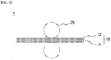
- FIG. 1 is a schematic diagram showing a general electrode rolling apparatus.
- an electrode rolling apparatus 1 includes a pair of rolling rolls 20. Further, the electrode 10 has a structure where an electrode active material layer 12 is formed on the current collector 11, and the electrode is inserted into a space between the rolling rolls 20 to thereby be rolled.
- the electrode in order to enhance the energy density of the electrode while constantly maintaining the thickness of the electrode, the electrode should be compressed as much as possible after enhancing the loading amount of the electrode.
- the surface of the electrode becomes smooth and hydrophobic, and as the number of pores, through which the electrolyte solution can permeate, on the surface of the electrode decreases, the impregnation property of the electrolyte solution decreases.
- an electrolyte solution is not sufficiently impregnated in the electrode, a dead volume of the electrode is generated.
- the deintercalation of lithium is not performed in the active material in the portion where the electrolyte solution is not impregnated, which causes charge imbalance of the electrode and a low voltage defect of the battery cell.
- the negative electrode lithium precipitation is caused in a portion where the electrolyte solution is not impregnated, and the safety of the cell is degraded.
- electrode active materials when the electrode is rolled, electrode active materials, etc. may be attached on the surface of the rolling rolls, and the electrode active materials may later act as contaminants during the rolling process. As such, since a separate rolling roll cleaning process is necessary, the time that takes in cleaning and the worker's safety may become a problem.
- an aspect of the present invention provides an electrode rolling apparatus and electrode rolling method capable of preventing reduction of impregnation property for an electrolyte solution of an electrode due to excessive compression of the electrode and preventing contamination of rolling rolls during the rolling process.
- An apparatus for rolling an electrode includes: a pair of rolling rolls which roll an electrode; and an adhesive tape which is inserted into the rolling rolls together with the electrode and is rolled together with the electrode, and is then separated from the electrode.
- the adhesive tape may include a substrate and an adhesive layer formed on one surface of the substrate.
- the adhesive layer may be formed on a surface where the substrate contacts the electrode.
- the apparatus may further include: an unwinding roll from which the adhesive tape is unwound; and a rewinding roll which winds the adhesive tape inserted into the rolling rolls after separating the adhesive tape from the electrode.
- the adhesive tape may further include a particulate material attached on a surface of an adhesive layer.
- the particulate material may be an inorganic material containing SiOx (0 ⁇ x ⁇ 2).
- the present invention provides a method of rolling an electrode.
- the method includes: preparing an electrode; inserting the electrode and an adhesive tape into a pair of rolling rolls to thereby roll the electrode and the adhesive tape; and changing a surface state of an electrode active material layer by separating the adhesive tape inserted into the rolling rolls from the electrode.
- the adhesive tape may include a substrate and an adhesive layer formed on one surface of the substrate.
- the adhesive layer may be formed on a surface where the substrate contacts the electrode.
- the adhesive tape may further include a particulate material attached on a surface of an adhesive layer.
- the particulate material may be an inorganic material containing SiOx (0 ⁇ x ⁇ 2).
- the particulate material may be transferred onto a surface of the electrode as the adhesive tape and the electrode are rolled together.
- the electrode rolling apparatus and method of the present invention it is possible to improve the impregnation property for the electrolyte solution of the electrode by changing the surface state of the electrode having a structure where electrode active materials have been aggregated on the surface by rolling the inserted adhesive tape together with the electrode at the time of rolling the electrode.
- contamination of the rolling rolls may be prevented by rolling the electrode and the adhesive tape together.
- An apparatus for rolling an electrode may include: a pair of rolling rolls which roll an electrode; and an adhesive tape which is inserted into the rolling rolls together with the electrode and is rolled together with the electrode, and is then separated from the electrode.
- the electrode in order to increase the energy density while maintaining the thickness of the electrode constant, the electrode should be compressed as much as possible after enhancing the loading amount of the electrode.
- the surface of the electrode becomes smooth and hydrophobic, and as the number of pores, through which the electrolyte solution can permeate, on the surface of the electrode decreases, the impregnation property of the electrolyte solution decreases.
- electrode active materials, etc. may be attached on the surface of the rolling rolls, and the electrode active materials may later act as contaminants during the rolling process.
- the electrode rolling apparatus and method of the present invention it is possible to improve the impregnation property for the electrolyte solution of the electrode by changing the surface state of the electrode having a structure where electrode active materials have been aggregated on the surface by rolling the inserted adhesive tape together with the electrode at the time of rolling the electrode.
- contamination of the rolling rolls may be prevented by rolling the electrode and the adhesive tape together.
- FIGS. 2 and 3 are schematic diagrams showing an electrode rolling apparatus according to an embodiment of the present invention.
- an apparatus 100 for rolling an electrode includes: a pair of rolling rolls 120 which roll an electrode 110; and an adhesive tape 130 which is inserted into the rolling rolls 120 together with the electrode 110 and is rolled together with the electrode 110, and is then separated from the electrode 110.
- the electrode 110 may have a structure where an electrode active material layer 112 is formed by applying an electrode slurry including an electrode active material on the current collector 111 and drying the electrode slurry.
- the current collector 111 may be a positive electrode current collector or a negative electrode current collector, and the electrode active material may be a positive electrode active material or a negative electrode active material.
- the electrode slurry may further include a conductive material and a binder in addition to the electrode active material.
- the positive electrode collector generally has a thickness of 3 to 500 ⁇ m.
- the positive electrode current collector is not particularly limited as long as it has high conductivity without causing a chemical change in the battery.
- Examples of the positive electrode current collector include stainless steel, aluminum, nickel, titanium, sintered carbon or aluminum or stainless steel of which the surface has been treated with carbon, nickel, titanium, silver, or the like.
- the current collector may have fine irregularities on the surface thereof to increase the adhesion of the positive electrode active material, and various forms such as a film, a sheet, a foil, a net, a porous body, a foam, and a nonwoven fabric are possible.
- the sheet for the negative electrode collector generally has a thickness of 3 to 500 ⁇ m.
- the negative electrode current collector is not particularly limited as long as it has electrical conductivity without causing chemical changes in the battery, and examples thereof include copper, stainless steel, aluminum, nickel, titanium, sintered carbon, copper or stainless steel of which the surface has been treated with carbon, nickel, titanium, silver or the like, aluminum-cadmium alloy, or the like.
- fine unevenness can be formed on the surface to enhance the bonding force of the negative electrode active material, and it can be used in various forms such as a film, a sheet, a foil, a net, a porous body, a foam, and a nonwoven fabric.
- the positive electrode active material is a material capable of causing an electrochemical reaction and a lithium transition metal oxide, and contains two or more transition metals.
- the negative electrode active material examples include carbon such as non-graphitized carbon and graphite carbon; metal complex oxide such as Li x Fe 2 O 3 (0 ⁇ x ⁇ 1), Li x WO 2 (0 ⁇ x ⁇ 1), Sn x Me 1-x Me' y O z (Me: Mn, Fe, Pb, Ge; Me': Al, B, P, Si, groups 1, 2, and 3 of the periodic table, halogen; 0 ⁇ x ⁇ 1; 1 ⁇ y ⁇ 3; 1 ⁇ z ⁇ 8); lithium metal; lithium alloy; silicon alloy; tin alloy; metal oxides such as SnO, SnO 2 , PbO, PbO 2 , Pb 2 O 3 , Pb 3 O 4 , Sb 2 O 3 , Sb 2 O 4 , Sb 2 O 5 , GeO, GeO 2 , Bi 2 O 3 , Bi 2 O 4 , and Bi 2 O 5 ; conductive polymers such as polyacetylene; and Li-Co-Ni-based materials.
- metal complex oxide such
- the conductive material is usually added in an amount of 1 to 30wt% based on the total weight of the mixture including the positive electrode active material.
- a conductive material is not particularly limited as long as it has electrical conductivity without causing a chemical change in the battery, and examples thereof include graphite such as natural graphite and artificial graphite; carbon black such as carbon black, acetylene black, Ketjen black, channel black, furnace black, lamp black, and summer black; conductive fibers such as carbon fiber and metal fiber; metal powders such as carbon fluoride, aluminum and nickel powder; conductive whiskey such as zinc oxide and potassium titanate; conductive metal oxides such as titanium oxide; and conductive materials such as polyphenylene derivatives and the like.
- the binder is added in an amount of 1 to 30wt%, on the basis of the total weight of the mixture containing the positive electrode active material, as a component that assists in bonding between the active material and the conductive material and bonding to the current collector.
- binders include polyvinylidene fluoride, polyvinyl alcohol, carboxymethylcellulose (CMC), starch, hydroxypropylcellulose, regenerated cellulose, polyvinylpyrrolidone, tetrafluoroethylene, polyethylene, polypropylene, ethylene-propylene-diene terpolymer (EPDM), sulfonated EPDM, styrene butylene rubber, fluorine rubber, various copolymers and the like.
- an electrode slurry may be prepared by dissolving an electrode active material, a conductive material, and a binder in a solvent.
- the type of the solvent is not particularly limited as long as it is capable of dispersing an electrode active material, and either an aqueous solvent or a non-aqueous solvent may be used.
- the solvent may be a solvent generally used in the art, such as dimethyl sulfoxide (DMSO), isopropyl alcohol, N-methylpyrrolidone (NMP ), acetone, or water, and one of them alone or a mixture of two or more may be used.
- the amount of the solvent used may be such that the slurry can be adjusted to have an appropriate viscosity in consideration of the coating thickness, production yield, and workability of the slurry, and is not particularly limited.
- the solvent may be removed in the drying process.
- the rolling rolls 120 are composed of a pair including an upper roll 121 positioned on the upper surface of the electrode 110 and a lower roll 122 positioned on the lower surface of the electrode 110 in order to roll the electrode 110.
- two or more pairs of rolling rolls 120 may be provided, and the number of the rolling rolls 120 may be appropriately designed by one of ordinary skill in the art.
- the electrode 110 may be inserted into a space between the upper roll 121 and the lower roll 122.
- the electrode rolling apparatus 100 further includes an adhesive tape 130.
- the adhesive tape 130 is inserted into the rolling rolls 120 together with the electrode 110 and is then rolled by the rolling rolls 120 together with the electrode 110. As the adhesive tape 130 is separated from the electrode 110 after rolled, the adhesive tape 130 can change the surface state of the electrode 110 by the rolling.
- the adhesive tape 130 may include a substrate 131 and an adhesive layer 132 formed on one surface of the substrate 131. At this time, the type of the substrate 131 and the adhesive layer 132 constituting the adhesive tape 130 can be appropriately designed by one of ordinary skill in the art.
- the substrate 131 may include a film or foam made of a thermoplastic resin, but the present invention is not limited to this example.
- the film made of a thermoplastic resin may contain at least one selected from the group consisting of urethane resin, acrylic resin, polyamide resin, polyester resin, polyether resin, polypropylene-polyethylene resin, polypropylene resin, polyethylene terephthalate resin, polybutylene terephthalate resin, polystyrene resin, acrylonitrile-styrene resin, acrylonitrile-butadiene-styrene resin, polyphenylene sulfide resin, nylon resin, polyether imide resin, and a combination thereof, and the present invention is not limited to these examples.
- urethane resin acrylic resin, polyamide resin, polyester resin, polyether resin, polypropylene-polyethylene resin, polypropylene resin, polyethylene terephthalate resin, polybutylene terephthalate resin, polystyrene resin, acrylonitrile-styrene resin, acrylonitrile-butadiene-styrene resin, polyphenylene
- the thickness of the substrate 131 may be appropriately designed by one of ordinary skill in the art, and it is necessary to have a sufficient mechanical strength in order not to be damaged during the rolling and winding process while not interfering with the rolling process of the electrode.
- the thickness of the substrate may be in the range of 10 to 150 ⁇ m, specifically in the range of 30 to 120 ⁇ m, and more specifically in the range of 50 to 100 ⁇ m.
- the thickness of the substrate is in the above range, it is possible to implement sufficient mechanical strength while not interfering with the rolling process of the electrode.
- the adhesive layer 132 may be made of a polymer material constituting an adhesive layer used in a general adhesive tape.
- the adhesive layer 132 may contain at least one selected from the group consisting of phenolic epoxy resin, polyimide resin, epoxy resin, acrylic resin, silicon resin, and polyurethane resin. More specifically, an acrylic resin or a polyurethane resin may be used as the adhesive layer.
- the composition of the adhesive layer may be appropriately designed by one of ordinary skill in the art in order to achieve the adhesive strength as follows.
- the thickness of the adhesive layer 132 would have been appropriately designed by one of ordinary skill in the art.
- the thickness may be in the range of 10 to 50 ⁇ m or 20 to 40 ⁇ m, but the present invention is not limited to these examples.
- the adhesive layer is excessively thick, it is not desirable because the adhesive tape may remain on the surface of the electrode when the adhesive tape is separated from the electrode.
- the adhesive layer 132 is formed on the surface where the substrate 131 contacts the electrode 110.
- the adhesive tape 130 is attached on the electrode 110 by the adhesive layer 132 as the adhesive tape 130 is rolled together with the electrode 110, and part of the electrode active material on the surface is peeled off from the electrode 110 by the adhesive layer 132 as the adhesive tape 130 is separated from the electrode 110 after the rolling.
- the electrode comes to be in a state that the electrolyte solution cannot be easily permeated by the rolling, and as the adhesive tape 130 peels off the electrode active material on the surface, the electrolyte solution can be easily permeated onto the peeled portion.
- the adhesive tape 130 may prevent the adhesive layer 132 on the adhesive tape 130 from remaining on the surface of the electrode by being separated from the electrode 110 right after the rolling.
- the adhesive tape 130 is interposed between the electrode 110 and the rolling rolls 120, it is possible to prevent electrode active materials from being attached on the rolling rolls 120 and acting as contaminants.
- the adhesive layer 132 is formed on only the surface contacting the electrode 110, and the adhesive layer is not formed on the surface where the rolling rolls 120 contact the adhesive tape 130. Hence, it is possible to prevent the elements of the adhesive layer 132 from being attached on the rolling rolls 120.
- the adhesive tape 130 preferably has an adhesive strength capable of detaching only electrode active materials on the surface of the electrode.
- the adhesive strength of the adhesive tape may be in the range of 50 to 2000 gf/ 25 mm, and more specifically in the range of 70 to 1000 gf/ 25 mm.
- the adhesive strength may be measured, for example, based on ASTM-D903. If the adhesive strength of the adhesive tape is beyond the above range and is excessively small, it is difficult to achieve the purpose of the present invention because it is difficult detach active materials on the surface of the electrode, and if the adhesive strength is excessively large, the amount of peeled active materials excessively increases, thereby damaging the electrode and deteriorating the quality of the electrode. Further, when the adhesive strength is excessively large, it may be difficult for particulate materials to be described later to be transferred onto the surface of the electrode.
- the adhesive tape 130 may be inserted into the rolling rolls 120 and moved at the same speed as the electrode 110 in order to be rolled together with the electrode 110.
- the apparatus 100 may further include: an unwinding roll 140 from which the adhesive tape 130 is unwound; and a rewinding roll 150 which winds the adhesive tape 130 inserted into the rolling rolls 120 after separating the adhesive tape 130 from the electrode 110.
- the unwinding roll 140 is a roll on which an already prepared adhesive tape 130 has been wound, and the adhesive tape 130 may be unwound and be inserted together with the electrode 110 at the time of the rolling process. Further, the rewinding roll 150 separately retrieves and winds the adhesive tape 130, which is attached on the surface of the electrode 110 by the rolling, from the electrode 110. At this time, one side of the adhesive tape 130 may have been wound on the unwinding roll 140, and the other side may have been wound on the rewinding roll 150. In this state, if the electrode 110 is inserted, the adhesive tape 130 may be rolled together with the electrode 110 while moving at the same speed as that of the electrode 110 by the rotation of the unwinding roll 140 and the rewinding roll 150. The adhesive tape 130 rolled together with the electrode 110 may be automatically separated from the electrode 110 as wound on the rewinding roll 150.
- the adhesive tape 130, the unwinding roll 140, and the rewinding roll 150 may be formed on one surface or both surfaces of the electrode 110.
- the electrode rolling apparatus 100 is about a case in which the electrode active material layer 112 is formed on only one surface of the current collector 111, and the adhesive tape 130 is positioned on only one surface of the electrode 110.
- the electrode rolling apparatus 200 is about a case in which the electrode active material layer 112 is formed on both surfaces of the current collector 111, and the adhesive tape 130 may be positioned on both surfaces of the electrode 110.
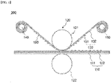
- FIG. 4 is a schematic diagram showing an electrode rolling apparatus according to another embodiment of the present invention.
- the electrode rolling apparatus 300 may include a rolling roll 120, an adhesive tape 130, an unwinding roll 140, and a rewinding roll 150 as described above.
- the adhesive tape 130 may further include a particulate material 160 attached on a surface of an adhesive layer 132.
- the particulate material 160 may be a material which is attached on the surface of the electrode 110 and is used to reform the electrode 110.
- the particulate material 160 is attached on the surface of the adhesive layer 132, and when rolled by the rolling rolls 120, the whole or part of the particulate material 160 may be transferred onto the surface of the electrode 110 or the surface of the electrode active material layer 112.
- the particulate material can be simply coated on the surface without a separate coating process, and accordingly, the process efficiency can be improved.
- the particulate material may be applied on the surface of the adhesive layer in a manner that does not excessively decrease the adhesive force of the adhesive tape, which may be appropriately designed by one of ordinary skill in the art.
- the particulate material 160 may be appropriately selected according to the performance of the electrode to be implemented or improved.
- inorganic particles may be used.
- the inorganic particle may be at least one selected from the group consisting of silicon oxide (SiOx, 0 ⁇ x ⁇ 2), alumina (Al 2 O 3 ), titanium dioxide (TiO 2 ), and tungsten oxide, and more preferably SiOx (0 ⁇ x ⁇ 2) may be used.
- SiOx silicon oxide
- 0 ⁇ x ⁇ 2 alumina
- TiO 2 titanium dioxide
- tungsten oxide preferably SiOx (0 ⁇ x ⁇ 2)
- Such particulate materials can improve the wetting property and the impregnation property for the electrolyte solution of the electrode by acting as the core which holds the electrolyte solution on the surface of the electrode.
- the amount of the particulate material applied on the surface of the electrode may be adjusted through the amount of the particulate material attached on the surface of the adhesive layer.
- the amount of the particulate material applied on the surface of the electrode may be appropriately adjusted by one of ordinary skill in the art.
- the average particle diameter (D 50 ) of the particulate material 160 may be appropriately designed by one of ordinary skill in the art.
- the average particle diameter may be in the range of 10 nm to 5 ⁇ m , specifically in the range of 10 nm to 3 ⁇ m, and more specifically in the range of 10 nm to 1 ⁇ m.
- the average particle diameter D 50 may be measured using, for example, a laser diffraction method. If the average particle diameter of the particulate material is excessively large, it may hinder permeation of the electrolyte solution and damage the separator facing the electrode mixture layer.
- the present invention provides an electrode rolling method.
- FIG. 5 is a flowchart illustrating an order of an electrode rolling method according to the present invention.
- a method of rolling an electrode according to the present invention includes: preparing an electrode (S 10); inserting the electrode and an adhesive tape into a pair of rolling rolls to thereby roll the electrode and the adhesive tape (S20); and changing a surface state of an electrode active material layer by separating the adhesive tape inserted into the rolling rolls from the electrode (S30).
- the electrode rolling apparatus and method of the present invention it is possible to improve the impregnation property for the electrolyte solution of the electrode by changing the surface state of the electrode having a structure where electrode active materials have been aggregated on the surface by rolling the inserted adhesive tape together with the electrode at the time of rolling the electrode.
- contamination of the rolling rolls may be prevented by rolling the electrode and the adhesive tape together.
- an electrode active material layer can be formed as an electrode slurry containing an electrode active material is coated on at least one surface of the current collector and is dried. The details about this are as described above.
- the adhesive tape includes a substrate and an adhesive layer formed on one surface of the substrate.
- the adhesive layer may be formed on a surface where the substrate contacts the electrode.
- the composition of the substrate and the adhesive layer is as described above.
- the adhesive layer is attached on the surface of the electrode, namely, the surface of the electrode active material layer, as the adhesive tape 130, which has been unwound from the unwinding roll 140, is inserted into a space between the rolling rolls. Thereafter, when the rolling is terminated, the adhesive tape is promptly separated from the electrode and is wound on the rewinding roll. At this time, the adhesive tape can be made to be promptly separated from the electrode after the rolling by allowing the adhesive tape to be moved in a state that the two sides of the adhesive tape have been wound on the unwinding roll and the rewinding roll before the electrode is inserted.
- part of the electrode active materials on the surface of the electrode active material layer may be detached by the adhesive tape by attaching and separating the adhesive tape at the time of the rolling, and through this, it is possible to change the surface of the electrode active material layer, which comes to have a hydrophobic property due to the rolling, to have a state in which the electrolyte solution can be better permeated.
- the adhesive tape may further include a particulate material attached on a surface of an adhesive layer.
- the adhesive tape is wound on the unwinding roll in a state that the particulate material has been attached on the surface of the adhesive layer, and the adhesive tape may be inserted together with the electrode.
- the particulate material may be appropriately selected according to the performance of the electrode to be implemented or improved.
- inorganic particles may be used.
- the inorganic particle may be at least one selected from the group consisting of silicon oxide (SiOx, 0 ⁇ x ⁇ 2), alumina (Al 2 O 3 ), titanium dioxide (TiO 2 ), and tungsten oxide, and more preferably SiOx (0 ⁇ x ⁇ 2) may be used.
- the particulate material is transferred onto a surface of the electrode as the adhesive tape and the electrode are rolled together.
- Such particulate materials can improve the wetting property and the impregnation property for the electrolyte solution of the electrode by acting as the core which holds the electrolyte solution on the surface of the electrode.
- the present invention provides a method of manufacturing a secondary battery including an electrode rolling method as described above.
- the secondary battery has a form where an electrode assembly, which has a form that a separator is interposed between a positive electrode and a negative electrode, is accommodated in a battery case.
- the positive electrode has a structure that a positive electrode active material layer is formed as a positive electrode slurry containing a positive electrode active material is applied on a positive electrode current collector, and the positive electrode and the negative electrode may have been manufactured and rolled by the above-described method.
- the separator is interposed between the positive electrode and the negative electrode, and an insulating thin film having high ion permeability and mechanical strength is used.
- the pore diameter of the separator is generally 0.01 to 10 ⁇ m, and the thickness is generally 5 to 300 ⁇ m.
- Examples of such a separator include olefin-based polymers such as polypropylene which is chemically resistant and hydrophobic; a sheet or a nonwoven fabric made of glass fiber, polyethylene or the like.
- the solid electrolyte such as a polymer is used as the electrolyte, the solid electrolyte may also serve as a separator.
- the battery case is not particularly limited as long as it is used as an exterior material for packaging the battery, and a cylindrical, square, or pouch type may be used.
- the electrolyte solution is injected and sealed. Thereafter, a final secondary battery is manufactured through the formation process. Details about the battery case and the electrolyte solution are known to those of ordinary skill in the art, and thus detailed description thereof will be omitted.
- Graphite of 88 wt% and SiO of 10 wt% as the negative electrode active material Graphite of 88 wt% and SiO of 10 wt% as the negative electrode active material, single walled carbon nanotube (SWCNT) of 0.05 wt% as the conductive material, styrene butadiene rubber (SBR) of 1.0 wt% as the binder, and CMC of 0.97 wt% as the thickener were added to water to thereby manufacture a negative electrode slurry.
- SWCNT single walled carbon nanotube
- SBR styrene butadiene rubber
- An electrode was manufactured by coating the negative electrode slurry on one surface of a copper current collector (thickness: 10 ⁇ m) and rolling the slurry-coated current collector and vacuum-drying the slurry-coated current collector at a vacuum oven at 120°C.
- the electrode was inserted into the rolling rolls together with the adhesive tape to thereby roll the electrode.
- OPP BOX tape adheresive strength: 72 gf/ 25 mm
- the adhesive tape is wound between the unwinding roll and the rewinding roll, and when the rolling is performed, the adhesive tape is unwound from the unwinding roll and is rolled together with the electrode as moved between the rolling rolls.
- the adhesive tape was separated from the electrode after the rolling process and was wound on the rewinding roll.
- the electrode was manufactured and was then rolled as in the example 1 except that N.4605 (adhesive strength: 922 gf/ 25 mm) of Nitto Denko Co., Ltd. was used as the adhesive tape.
- the electrode was manufactured and was then rolled as in the example 1 except that N.9070 (adhesive strength: 1727 gf/ 25 mm) of 3M company was used as the adhesive tape.
- the electrode was manufactured and was then rolled as in the example 1 except that the electrode was rolled by a conventional rolling method as in FIG. 1 without using the adhesive tape.
- the electrolyte solution impregnation property was evaluated for the electrode according to the examples 1 to 3 and the comparative example. Specific evaluation items are as follows.
- PC impregnation time evaluation 20 samples were prepared for each electrode manufactured according to each example and comparative example. After dropping 1 ml propylene carbonate (PC) as the electrolyte solution on the surface of each sample using a syringe, time until the solvent was absorbed in the electrode was measured. The measurement result was obtained by calculating the average for results of 20 samples. The results are shown in Table 1. [Table 1] Evaluation item Example 1 Example 2 Example 3 Comparative example PC impregnation time (sec) 72 65 70 140
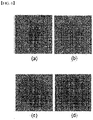
- FIG. 6(a) is a photograph obtained by photographing the surface of an electrode according to a comparative example
- FIGS. 6(b) to 6(d) shows photographs obtained by photographing the surface of an electrode according to examples 1 to 3.
- the impregnation time of the electrolyte solution more decreased, compared to the comparative example. This means that part of the tightly aggregated electrode active material has been peeled off by contacting the adhesive tape at the time of rolling the electrode and separating the adhesive tape after the rolling, and accordingly the surface state of the electrode has been changed and the impregnation property has been improved.
- the electrolyte solution is more spread out in the electrode according to the examples than in the comparative example at the time of injecting the electrolyte solution. Namely, it is seen that the electrode according to the example has more improved in the impregnation property than in the comparative example.
Landscapes
- Chemical & Material Sciences (AREA)
- Engineering & Computer Science (AREA)
- Chemical Kinetics & Catalysis (AREA)
- Electrochemistry (AREA)
- General Chemical & Material Sciences (AREA)
- Manufacturing & Machinery (AREA)
- Materials Engineering (AREA)
- Battery Electrode And Active Subsutance (AREA)
- Metal Rolling (AREA)
Abstract
Description
- This application claims the benefit of priority based on
Korean Patent Application No. 10-2020-0155837, filed on November 19, 2020 - The present invention relates to an electrode rolling apparatus and an electrode rolling method.
- Recently, secondary batteries capable of charging and discharging have been widely used as energy sources of wireless mobile devices. In addition, the secondary battery has attracted attention as an energy source of an electric vehicle, a hybrid electric vehicle, etc., which are proposed as a solution for air pollution of existing gasoline vehicles and diesel vehicles using fossil fuel. Therefore, the types of applications using the secondary battery are currently much diversified due to the advantages of the secondary battery, and it is expected that the secondary battery will be applied to many fields and products in the future.
- Such secondary batteries may be classified into lithium ion batteries, lithium ion polymer batteries, lithium polymer batteries, etc., depending on the composition of the electrode and the electrolyte, and among them, the amount of use of lithium-ion polymer batteries that are less likely to leak electrolyte and are easy to manufacture is on the increase. In general, secondary batteries are classified into cylindrical batteries and prismatic batteries in which an electrode assembly is embedded in a cylindrical or rectangular metal can, depending on the shape of a battery case, and pouch-type batteries in which the electrode assembly is embedded in a pouch-type case of an aluminum laminate sheet. The electrode assembly built into the battery case is composed of a positive electrode, a negative electrode, and a separator interposed between the positive electrode and the negative electrode, and is a power generating element capable of charging and discharging. The electrode assembly is classified into a jelly-roll type wound with a separator interposed between the positive electrode and the negative electrode which are long sheet-shaped and are coated with active materials, and a stack type in which a plurality of positive electrodes and negative electrodes of a predetermined size are sequentially stacked while a separator is interposed therebetween.
- Such an electrode may be manufactured by applying an electrode slurry containing an electrode active material and a solvent on a current collector to form an electrode active material layer, followed by drying and rolling.
-
FIG. 1 is a schematic diagram showing a general electrode rolling apparatus. - Referring to
FIG. 1 , anelectrode rolling apparatus 1 includes a pair of rollingrolls 20. Further, theelectrode 10 has a structure where an electrodeactive material layer 12 is formed on thecurrent collector 11, and the electrode is inserted into a space between therolling rolls 20 to thereby be rolled. - At this time, in order to enhance the energy density of the electrode while constantly maintaining the thickness of the electrode, the electrode should be compressed as much as possible after enhancing the loading amount of the electrode. However, in this case, as the particles constituting the electrode active material layer are aggregated by excessive compression, the surface of the electrode becomes smooth and hydrophobic, and as the number of pores, through which the electrolyte solution can permeate, on the surface of the electrode decreases, the impregnation property of the electrolyte solution decreases.
- Likewise, if an electrolyte solution is not sufficiently impregnated in the electrode, a dead volume of the electrode is generated. In the case of the positive electrode, the deintercalation of lithium is not performed in the active material in the portion where the electrolyte solution is not impregnated, which causes charge imbalance of the electrode and a low voltage defect of the battery cell. In the case of the negative electrode, lithium precipitation is caused in a portion where the electrolyte solution is not impregnated, and the safety of the cell is degraded.
- Further, when the electrode is rolled, electrode active materials, etc. may be attached on the surface of the rolling rolls, and the electrode active materials may later act as contaminants during the rolling process. As such, since a separate rolling roll cleaning process is necessary, the time that takes in cleaning and the worker's safety may become a problem.
- The present invention is believed to solve at least some of the above problems. For example, an aspect of the present invention provides an electrode rolling apparatus and electrode rolling method capable of preventing reduction of impregnation property for an electrolyte solution of an electrode due to excessive compression of the electrode and preventing contamination of rolling rolls during the rolling process.
- An apparatus for rolling an electrode according to an embodiment of the present invention includes: a pair of rolling rolls which roll an electrode; and an adhesive tape which is inserted into the rolling rolls together with the electrode and is rolled together with the electrode, and is then separated from the electrode.
- In a specific example, the adhesive tape may include a substrate and an adhesive layer formed on one surface of the substrate.
- In a specific example, the adhesive layer may be formed on a surface where the substrate contacts the electrode.
- In a specific example, the apparatus may further include: an unwinding roll from which the adhesive tape is unwound; and a rewinding roll which winds the adhesive tape inserted into the rolling rolls after separating the adhesive tape from the electrode.
- In another example, the adhesive tape may further include a particulate material attached on a surface of an adhesive layer.
- In a specific example, the particulate material may be an inorganic material containing SiOx (0<x≤2).
- Further, the present invention provides a method of rolling an electrode. The method includes: preparing an electrode; inserting the electrode and an adhesive tape into a pair of rolling rolls to thereby roll the electrode and the adhesive tape; and changing a surface state of an electrode active material layer by separating the adhesive tape inserted into the rolling rolls from the electrode.
- In a specific example, the adhesive tape may include a substrate and an adhesive layer formed on one surface of the substrate.
- In a specific example, the adhesive layer may be formed on a surface where the substrate contacts the electrode.
- In a specific example, the adhesive tape may further include a particulate material attached on a surface of an adhesive layer.
- In a specific example, the particulate material may be an inorganic material containing SiOx (0<x≤2).
- At this time, the particulate material may be transferred onto a surface of the electrode as the adhesive tape and the electrode are rolled together.
- Further, according to the electrode rolling apparatus and method of the present invention, it is possible to improve the impregnation property for the electrolyte solution of the electrode by changing the surface state of the electrode having a structure where electrode active materials have been aggregated on the surface by rolling the inserted adhesive tape together with the electrode at the time of rolling the electrode.
- Further, according to the electrode rolling apparatus and method of the present invention, contamination of the rolling rolls may be prevented by rolling the electrode and the adhesive tape together.
-
-
FIG. 1 is a schematic diagram showing a general electrode rolling apparatus. -
FIGS. 2 and3 are schematic diagrams showing an electrode rolling apparatus according to an embodiment of the present invention. -
FIG. 4 is a schematic diagram showing an electrode rolling apparatus according to another embodiment of the present invention. -
FIG. 5 is a flowchart illustrating an order of an electrode rolling method according to the present invention. -
FIG. 6 shows photographs of surfaces of electrodes according to examples and comparative examples after dropping an electrolyte solution. - Hereinafter, the present invention will be described in detail with reference to the drawings. The terms and words used in the present specification and claims should not be construed as limited to ordinary or dictionary terms and the inventor may properly define the concept of the terms in order to best describe its invention. The terms and words should be construed as meaning and concept consistent with the technical idea of the present invention.
- In this application, it should be understood that terms such as "include" or "have" are intended to indicate that there is a feature, number, step, operation, component, part, or a combination thereof described on the specification, and they do not exclude in advance the possibility of the presence or addition of one or more other features or numbers, steps, operations, components, parts or combinations thereof. Also, when a portion such as a layer, a film, an area, a plate, etc. is referred to as being "on" another portion, this includes not only the case where the portion is "directly on" the another portion but also the case where further another portion is interposed therebetween. On the other hand, when a portion such as a layer, a film, an area, a plate, etc. is referred to as being "under" another portion, this includes not only the case where the portion is "directly under" the another portion but also the case where further another portion is interposed therebetween. In addition, to be disposed "on" in the present application may include the case disposed at the bottom as well as the top.
- Hereinafter, the present invention will be described in detail with reference to the drawings.
- An apparatus for rolling an electrode according to an embodiment of the present invention may include: a pair of rolling rolls which roll an electrode; and an adhesive tape which is inserted into the rolling rolls together with the electrode and is rolled together with the electrode, and is then separated from the electrode.
- As described above, in the conventional rolling device and method, in order to increase the energy density while maintaining the thickness of the electrode constant, the electrode should be compressed as much as possible after enhancing the loading amount of the electrode. In this case, as the particles constituting the electrode active material layer are aggregated by excessive compression, the surface of the electrode becomes smooth and hydrophobic, and as the number of pores, through which the electrolyte solution can permeate, on the surface of the electrode decreases, the impregnation property of the electrolyte solution decreases. Further, when the electrode is rolled, electrode active materials, etc. may be attached on the surface of the rolling rolls, and the electrode active materials may later act as contaminants during the rolling process.
- Further, according to the electrode rolling apparatus and method of the present invention, it is possible to improve the impregnation property for the electrolyte solution of the electrode by changing the surface state of the electrode having a structure where electrode active materials have been aggregated on the surface by rolling the inserted adhesive tape together with the electrode at the time of rolling the electrode.
- Further, according to the electrode rolling apparatus and method of the present invention, contamination of the rolling rolls may be prevented by rolling the electrode and the adhesive tape together.
- Hereinafter, an electrode rolling apparatus and an electrode rolling method according to the present invention will be described in detail.
-
FIGS. 2 and3 are schematic diagrams showing an electrode rolling apparatus according to an embodiment of the present invention. - Referring to
FIGS. 2 and3 , anapparatus 100 for rolling an electrode according to the present invention includes: a pair of rollingrolls 120 which roll anelectrode 110; and anadhesive tape 130 which is inserted into the rolling rolls 120 together with theelectrode 110 and is rolled together with theelectrode 110, and is then separated from theelectrode 110. - The
electrode 110 may have a structure where an electrodeactive material layer 112 is formed by applying an electrode slurry including an electrode active material on thecurrent collector 111 and drying the electrode slurry. - The
current collector 111 may be a positive electrode current collector or a negative electrode current collector, and the electrode active material may be a positive electrode active material or a negative electrode active material. In addition, the electrode slurry may further include a conductive material and a binder in addition to the electrode active material. - In the present invention, the positive electrode collector generally has a thickness of 3 to 500 µm. The positive electrode current collector is not particularly limited as long as it has high conductivity without causing a chemical change in the battery. Examples of the positive electrode current collector include stainless steel, aluminum, nickel, titanium, sintered carbon or aluminum or stainless steel of which the surface has been treated with carbon, nickel, titanium, silver, or the like. The current collector may have fine irregularities on the surface thereof to increase the adhesion of the positive electrode active material, and various forms such as a film, a sheet, a foil, a net, a porous body, a foam, and a nonwoven fabric are possible.
- The sheet for the negative electrode collector generally has a thickness of 3 to 500 µm. The negative electrode current collector is not particularly limited as long as it has electrical conductivity without causing chemical changes in the battery, and examples thereof include copper, stainless steel, aluminum, nickel, titanium, sintered carbon, copper or stainless steel of which the surface has been treated with carbon, nickel, titanium, silver or the like, aluminum-cadmium alloy, or the like. In addition, like the positive electrode current collector, fine unevenness can be formed on the surface to enhance the bonding force of the negative electrode active material, and it can be used in various forms such as a film, a sheet, a foil, a net, a porous body, a foam, and a nonwoven fabric.
- In the present invention, the positive electrode active material is a material capable of causing an electrochemical reaction and a lithium transition metal oxide, and contains two or more transition metals. Examples thereof include: layered compounds such as lithium cobalt oxide (LiCoO2) and lithium nickel oxide (LiNiO2) substituted with one or more transition metals; lithium manganese oxide substituted with one or more transition metals; lithium nickel oxide represented by the formula LiNi1-yMyO2 (wherein M = Co, Mn, Al, Cu, Fe, Mg, B, Cr, Zn or Ga and contains at least one of the above elements, 0.01 ≦ y ≦ 0.7); lithium nickel cobalt manganese composite oxide represented by the formula Li1+zNibMncCo1-(b+c+d)MdO(2-e)Ae such as Li1+zNi1/3Co1/3Mn1/3O2, Li1+zNi0.4Mn0.4Co0.2O2 etc. (wherein - 0.5≤z≤0.5, 0.1≤b≤0.8, 0.1≤c≤0.8, 0≤d≤0.2, 0≤e≤0.2, b+c+d< 1, M = Al, Mg, Cr, Ti, Si or Y, and A = F, P or Cl); olivine-based lithium metal phosphate represented by the formula Li1+xM1-yM'yPO4-zXz (wherein M = transition metal, preferably Fe, Mn, Co or Ni, M'= Al, Mg or Ti, X = F, S or N, and -0.5≤x≤0.5, 0≤y≤0.5, 0≤z≤0.1). But the present invention is not limited to these examples. Examples of the negative electrode active material include carbon such as non-graphitized carbon and graphite carbon; metal complex oxide such as LixFe2O3(0≤x≤1), LixWO2(0≤x≤1), SnxMe1-xMe'yOz (Me: Mn, Fe, Pb, Ge; Me': Al, B, P, Si,
groups 1, 2, and 3 of the periodic table, halogen; 0<x≤1; 1≤y≤3; 1≤z≤8); lithium metal; lithium alloy; silicon alloy; tin alloy; metal oxides such as SnO, SnO2, PbO, PbO2, Pb2O3, Pb3O4, Sb2O3, Sb2O4, Sb2O5, GeO, GeO2, Bi2O3, Bi2O4, and Bi2O5; conductive polymers such as polyacetylene; and Li-Co-Ni-based materials. - The conductive material is usually added in an amount of 1 to 30wt% based on the total weight of the mixture including the positive electrode active material. Such a conductive material is not particularly limited as long as it has electrical conductivity without causing a chemical change in the battery, and examples thereof include graphite such as natural graphite and artificial graphite; carbon black such as carbon black, acetylene black, Ketjen black, channel black, furnace black, lamp black, and summer black; conductive fibers such as carbon fiber and metal fiber; metal powders such as carbon fluoride, aluminum and nickel powder; conductive whiskey such as zinc oxide and potassium titanate; conductive metal oxides such as titanium oxide; and conductive materials such as polyphenylene derivatives and the like.
- The binder is added in an amount of 1 to 30wt%, on the basis of the total weight of the mixture containing the positive electrode active material, as a component that assists in bonding between the active material and the conductive material and bonding to the current collector. Examples of such binders include polyvinylidene fluoride, polyvinyl alcohol, carboxymethylcellulose (CMC), starch, hydroxypropylcellulose, regenerated cellulose, polyvinylpyrrolidone, tetrafluoroethylene, polyethylene, polypropylene, ethylene-propylene-diene terpolymer (EPDM), sulfonated EPDM, styrene butylene rubber, fluorine rubber, various copolymers and the like.
- Meanwhile, such an electrode slurry may be prepared by dissolving an electrode active material, a conductive material, and a binder in a solvent. The type of the solvent is not particularly limited as long as it is capable of dispersing an electrode active material, and either an aqueous solvent or a non-aqueous solvent may be used. For example, the solvent may be a solvent generally used in the art, such as dimethyl sulfoxide (DMSO), isopropyl alcohol, N-methylpyrrolidone (NMP ), acetone, or water, and one of them alone or a mixture of two or more may be used. The amount of the solvent used may be such that the slurry can be adjusted to have an appropriate viscosity in consideration of the coating thickness, production yield, and workability of the slurry, and is not particularly limited. The solvent may be removed in the drying process.
- Further, the rolling rolls 120 are composed of a pair including an
upper roll 121 positioned on the upper surface of theelectrode 110 and alower roll 122 positioned on the lower surface of theelectrode 110 in order to roll theelectrode 110. In the rolling apparatus according to the present invention, two or more pairs of rollingrolls 120 may be provided, and the number of the rolling rolls 120 may be appropriately designed by one of ordinary skill in the art. Theelectrode 110 may be inserted into a space between theupper roll 121 and thelower roll 122. - Further, the
electrode rolling apparatus 100 according to the present invention further includes anadhesive tape 130. Theadhesive tape 130 is inserted into the rolling rolls 120 together with theelectrode 110 and is then rolled by the rolling rolls 120 together with theelectrode 110. As theadhesive tape 130 is separated from theelectrode 110 after rolled, theadhesive tape 130 can change the surface state of theelectrode 110 by the rolling. - The
adhesive tape 130 may include asubstrate 131 and anadhesive layer 132 formed on one surface of thesubstrate 131. At this time, the type of thesubstrate 131 and theadhesive layer 132 constituting theadhesive tape 130 can be appropriately designed by one of ordinary skill in the art. - For example, the
substrate 131 may include a film or foam made of a thermoplastic resin, but the present invention is not limited to this example. - The film made of a thermoplastic resin may contain at least one selected from the group consisting of urethane resin, acrylic resin, polyamide resin, polyester resin, polyether resin, polypropylene-polyethylene resin, polypropylene resin, polyethylene terephthalate resin, polybutylene terephthalate resin, polystyrene resin, acrylonitrile-styrene resin, acrylonitrile-butadiene-styrene resin, polyphenylene sulfide resin, nylon resin, polyether imide resin, and a combination thereof, and the present invention is not limited to these examples.
- The thickness of the
substrate 131 may be appropriately designed by one of ordinary skill in the art, and it is necessary to have a sufficient mechanical strength in order not to be damaged during the rolling and winding process while not interfering with the rolling process of the electrode. For example, the thickness of the substrate may be in the range of 10 to 150 µm, specifically in the range of 30 to 120 µm, and more specifically in the range of 50 to 100 µm. When the thickness of the substrate is in the above range, it is possible to implement sufficient mechanical strength while not interfering with the rolling process of the electrode. - Further, the
adhesive layer 132 may be made of a polymer material constituting an adhesive layer used in a general adhesive tape. For example, theadhesive layer 132 may contain at least one selected from the group consisting of phenolic epoxy resin, polyimide resin, epoxy resin, acrylic resin, silicon resin, and polyurethane resin. More specifically, an acrylic resin or a polyurethane resin may be used as the adhesive layer. The composition of the adhesive layer may be appropriately designed by one of ordinary skill in the art in order to achieve the adhesive strength as follows. - The thickness of the
adhesive layer 132 would have been appropriately designed by one of ordinary skill in the art. For example, the thickness may be in the range of 10 to 50 µm or 20 to 40 µm, but the present invention is not limited to these examples. Herein, if the adhesive layer is excessively thick, it is not desirable because the adhesive tape may remain on the surface of the electrode when the adhesive tape is separated from the electrode. - Further, the
adhesive layer 132 is formed on the surface where thesubstrate 131 contacts theelectrode 110. Namely, in the present invention, theadhesive tape 130 is attached on theelectrode 110 by theadhesive layer 132 as theadhesive tape 130 is rolled together with theelectrode 110, and part of the electrode active material on the surface is peeled off from theelectrode 110 by theadhesive layer 132 as theadhesive tape 130 is separated from theelectrode 110 after the rolling. Generally, the electrode comes to be in a state that the electrolyte solution cannot be easily permeated by the rolling, and as theadhesive tape 130 peels off the electrode active material on the surface, the electrolyte solution can be easily permeated onto the peeled portion. More specifically, theadhesive tape 130 may prevent theadhesive layer 132 on theadhesive tape 130 from remaining on the surface of the electrode by being separated from theelectrode 110 right after the rolling. - Further, as the
adhesive tape 130 is interposed between theelectrode 110 and the rolling rolls 120, it is possible to prevent electrode active materials from being attached on the rolling rolls 120 and acting as contaminants. At this time, theadhesive layer 132 is formed on only the surface contacting theelectrode 110, and the adhesive layer is not formed on the surface where the rolling rolls 120 contact theadhesive tape 130. Hence, it is possible to prevent the elements of theadhesive layer 132 from being attached on the rolling rolls 120. - The
adhesive tape 130 preferably has an adhesive strength capable of detaching only electrode active materials on the surface of the electrode. Specifically, the adhesive strength of the adhesive tape may be in the range of 50 to 2000 gf/ 25 mm, and more specifically in the range of 70 to 1000 gf/ 25 mm. The adhesive strength may be measured, for example, based on ASTM-D903. If the adhesive strength of the adhesive tape is beyond the above range and is excessively small, it is difficult to achieve the purpose of the present invention because it is difficult detach active materials on the surface of the electrode, and if the adhesive strength is excessively large, the amount of peeled active materials excessively increases, thereby damaging the electrode and deteriorating the quality of the electrode. Further, when the adhesive strength is excessively large, it may be difficult for particulate materials to be described later to be transferred onto the surface of the electrode. - The
adhesive tape 130 may be inserted into the rolling rolls 120 and moved at the same speed as theelectrode 110 in order to be rolled together with theelectrode 110. To this end, theapparatus 100 may further include: an unwindingroll 140 from which theadhesive tape 130 is unwound; and a rewindingroll 150 which winds theadhesive tape 130 inserted into the rolling rolls 120 after separating theadhesive tape 130 from theelectrode 110. - The unwinding
roll 140 is a roll on which an already preparedadhesive tape 130 has been wound, and theadhesive tape 130 may be unwound and be inserted together with theelectrode 110 at the time of the rolling process. Further, the rewindingroll 150 separately retrieves and winds theadhesive tape 130, which is attached on the surface of theelectrode 110 by the rolling, from theelectrode 110. At this time, one side of theadhesive tape 130 may have been wound on the unwindingroll 140, and the other side may have been wound on the rewindingroll 150. In this state, if theelectrode 110 is inserted, theadhesive tape 130 may be rolled together with theelectrode 110 while moving at the same speed as that of theelectrode 110 by the rotation of the unwindingroll 140 and the rewindingroll 150. Theadhesive tape 130 rolled together with theelectrode 110 may be automatically separated from theelectrode 110 as wound on the rewindingroll 150. - At this time, the
adhesive tape 130, the unwindingroll 140, and the rewindingroll 150 may be formed on one surface or both surfaces of theelectrode 110. In the case ofFIG. 2 , theelectrode rolling apparatus 100 is about a case in which the electrodeactive material layer 112 is formed on only one surface of thecurrent collector 111, and theadhesive tape 130 is positioned on only one surface of theelectrode 110. Further, in the case ofFIG. 3 , theelectrode rolling apparatus 200 is about a case in which the electrodeactive material layer 112 is formed on both surfaces of thecurrent collector 111, and theadhesive tape 130 may be positioned on both surfaces of theelectrode 110. -
FIG. 4 is a schematic diagram showing an electrode rolling apparatus according to another embodiment of the present invention. - Referring to
FIG. 4 , theelectrode rolling apparatus 300 may include a rollingroll 120, anadhesive tape 130, an unwindingroll 140, and a rewindingroll 150 as described above. At this time, theadhesive tape 130 may further include aparticulate material 160 attached on a surface of anadhesive layer 132. Herein, theparticulate material 160 may be a material which is attached on the surface of theelectrode 110 and is used to reform theelectrode 110. Theparticulate material 160 is attached on the surface of theadhesive layer 132, and when rolled by the rolling rolls 120, the whole or part of theparticulate material 160 may be transferred onto the surface of theelectrode 110 or the surface of the electrodeactive material layer 112. Namely, according to the present invention, the particulate material can be simply coated on the surface without a separate coating process, and accordingly, the process efficiency can be improved. The particulate material may be applied on the surface of the adhesive layer in a manner that does not excessively decrease the adhesive force of the adhesive tape, which may be appropriately designed by one of ordinary skill in the art. - The
particulate material 160 may be appropriately selected according to the performance of the electrode to be implemented or improved. In a specific example, inorganic particles may be used. The inorganic particle may be at least one selected from the group consisting of silicon oxide (SiOx, 0<x≤2), alumina (Al2O3), titanium dioxide (TiO2), and tungsten oxide, and more preferably SiOx (0<x≤2) may be used. Such particulate materials can improve the wetting property and the impregnation property for the electrolyte solution of the electrode by acting as the core which holds the electrolyte solution on the surface of the electrode. The amount of the particulate material applied on the surface of the electrode may be adjusted through the amount of the particulate material attached on the surface of the adhesive layer. The amount of the particulate material applied on the surface of the electrode may be appropriately adjusted by one of ordinary skill in the art. - Further, the average particle diameter (D50) of the
particulate material 160 may be appropriately designed by one of ordinary skill in the art. For example, the average particle diameter may be in the range of 10 nm to 5µm , specifically in the range of 10 nm to 3 µm, and more specifically in the range of 10 nm to 1 µm. The average particle diameter D50 may be measured using, for example, a laser diffraction method. If the average particle diameter of the particulate material is excessively large, it may hinder permeation of the electrolyte solution and damage the separator facing the electrode mixture layer. - In addition, the present invention provides an electrode rolling method.
-
FIG. 5 is a flowchart illustrating an order of an electrode rolling method according to the present invention. - Referring to
FIG. 5 , a method of rolling an electrode according to the present invention includes: preparing an electrode (S 10); inserting the electrode and an adhesive tape into a pair of rolling rolls to thereby roll the electrode and the adhesive tape (S20); and changing a surface state of an electrode active material layer by separating the adhesive tape inserted into the rolling rolls from the electrode (S30). - Further, according to the electrode rolling apparatus and method of the present invention, it is possible to improve the impregnation property for the electrolyte solution of the electrode by changing the surface state of the electrode having a structure where electrode active materials have been aggregated on the surface by rolling the inserted adhesive tape together with the electrode at the time of rolling the electrode.
- Further, according to the electrode rolling apparatus and method of the present invention, contamination of the rolling rolls may be prevented by rolling the electrode and the adhesive tape together.
- First, when preparing an electrode, an electrode active material layer can be formed as an electrode slurry containing an electrode active material is coated on at least one surface of the current collector and is dried. The details about this are as described above.
- When an electrode is prepared, the electrode and an adhesive tape are inserted into a pair of rolling rolls to thereby roll the electrode. The adhesive tape includes a substrate and an adhesive layer formed on one surface of the substrate. The adhesive layer may be formed on a surface where the substrate contacts the electrode. The composition of the substrate and the adhesive layer is as described above.
- Referring to
FIG. 5 withFIG. 2 orFIG. 3 , the adhesive layer is attached on the surface of the electrode, namely, the surface of the electrode active material layer, as theadhesive tape 130, which has been unwound from the unwindingroll 140, is inserted into a space between the rolling rolls. Thereafter, when the rolling is terminated, the adhesive tape is promptly separated from the electrode and is wound on the rewinding roll. At this time, the adhesive tape can be made to be promptly separated from the electrode after the rolling by allowing the adhesive tape to be moved in a state that the two sides of the adhesive tape have been wound on the unwinding roll and the rewinding roll before the electrode is inserted. - Likewise, part of the electrode active materials on the surface of the electrode active material layer may be detached by the adhesive tape by attaching and separating the adhesive tape at the time of the rolling, and through this, it is possible to change the surface of the electrode active material layer, which comes to have a hydrophobic property due to the rolling, to have a state in which the electrolyte solution can be better permeated.
- The adhesive tape may further include a particulate material attached on a surface of an adhesive layer. The adhesive tape is wound on the unwinding roll in a state that the particulate material has been attached on the surface of the adhesive layer, and the adhesive tape may be inserted together with the electrode.
- The particulate material may be appropriately selected according to the performance of the electrode to be implemented or improved. In a specific example, inorganic particles may be used. The inorganic particle may be at least one selected from the group consisting of silicon oxide (SiOx, 0<x≤2), alumina (Al2O3), titanium dioxide (TiO2), and tungsten oxide, and more preferably SiOx (0<x≤2) may be used.
- The particulate material is transferred onto a surface of the electrode as the adhesive tape and the electrode are rolled together. Such particulate materials can improve the wetting property and the impregnation property for the electrolyte solution of the electrode by acting as the core which holds the electrolyte solution on the surface of the electrode.
- Further, the present invention provides a method of manufacturing a secondary battery including an electrode rolling method as described above.
- The secondary battery has a form where an electrode assembly, which has a form that a separator is interposed between a positive electrode and a negative electrode, is accommodated in a battery case. The positive electrode has a structure that a positive electrode active material layer is formed as a positive electrode slurry containing a positive electrode active material is applied on a positive electrode current collector, and the positive electrode and the negative electrode may have been manufactured and rolled by the above-described method.
- The separator is interposed between the positive electrode and the negative electrode, and an insulating thin film having high ion permeability and mechanical strength is used. The pore diameter of the separator is generally 0.01 to 10 µm, and the thickness is generally 5 to 300 µm. Examples of such a separator include olefin-based polymers such as polypropylene which is chemically resistant and hydrophobic; a sheet or a nonwoven fabric made of glass fiber, polyethylene or the like. When a solid electrolyte such as a polymer is used as the electrolyte, the solid electrolyte may also serve as a separator.
- Further, the battery case is not particularly limited as long as it is used as an exterior material for packaging the battery, and a cylindrical, square, or pouch type may be used. When an electrode assembly is accommodated in a battery case, the electrolyte solution is injected and sealed. Thereafter, a final secondary battery is manufactured through the formation process. Details about the battery case and the electrolyte solution are known to those of ordinary skill in the art, and thus detailed description thereof will be omitted.
- Hereinafter, the present invention will be described in detail with reference to examples. However, the embodiments according to the present invention may be modified into various other forms, and the scope of the present invention should not be construed as being limited to the examples described below. The examples of the present invention are provided to more fully describe the present invention to those skilled in the art.
- Graphite of 88 wt% and SiO of 10 wt% as the negative electrode active material, single walled carbon nanotube (SWCNT) of 0.05 wt% as the conductive material, styrene butadiene rubber (SBR) of 1.0 wt% as the binder, and CMC of 0.97 wt% as the thickener were added to water to thereby manufacture a negative electrode slurry.
- An electrode was manufactured by coating the negative electrode slurry on one surface of a copper current collector (thickness: 10 µm) and rolling the slurry-coated current collector and vacuum-drying the slurry-coated current collector at a vacuum oven at 120°C.
- The electrode was inserted into the rolling rolls together with the adhesive tape to thereby roll the electrode. Specifically, OPP BOX tape (adhesive strength: 72 gf/ 25 mm) was used as the adhesive tape. As shown in
FIG. 2 , the adhesive tape is wound between the unwinding roll and the rewinding roll, and when the rolling is performed, the adhesive tape is unwound from the unwinding roll and is rolled together with the electrode as moved between the rolling rolls. The adhesive tape was separated from the electrode after the rolling process and was wound on the rewinding roll. - The electrode was manufactured and was then rolled as in the example 1 except that N.4605 (adhesive strength: 922 gf/ 25 mm) of Nitto Denko Co., Ltd. was used as the adhesive tape.
- The electrode was manufactured and was then rolled as in the example 1 except that N.9070 (adhesive strength: 1727 gf/ 25 mm) of 3M company was used as the adhesive tape.
- The electrode was manufactured and was then rolled as in the example 1 except that the electrode was rolled by a conventional rolling method as in
FIG. 1 without using the adhesive tape. - The electrolyte solution impregnation property was evaluated for the electrode according to the examples 1 to 3 and the comparative example. Specific evaluation items are as follows.
- PC impregnation time evaluation: 20 samples were prepared for each electrode manufactured according to each example and comparative example. After dropping 1 ml propylene carbonate (PC) as the electrolyte solution on the surface of each sample using a syringe, time until the solvent was absorbed in the electrode was measured. The measurement result was obtained by calculating the average for results of 20 samples. The results are shown in Table 1.
[Table 1] Evaluation item Example 1 Example 2 Example 3 Comparative example PC impregnation time (sec) 72 65 70 140 - Electrolyte solution spreadability evaluation: 1 ml of 1M LiPF6 carbonate-based solution as the electrolyte solution was dropped on the surface of each electrode, and the spreadability of the electrolyte solution on the surface of the electrode was then observed. The result was shown in
FIG. 6. FIG. 6(a) is a photograph obtained by photographing the surface of an electrode according to a comparative example,FIGS. 6(b) to 6(d) shows photographs obtained by photographing the surface of an electrode according to examples 1 to 3. - Referring to Table 1, in the case of the electrode according to examples 1 to 3, the impregnation time of the electrolyte solution more decreased, compared to the comparative example. This means that part of the tightly aggregated electrode active material has been peeled off by contacting the adhesive tape at the time of rolling the electrode and separating the adhesive tape after the rolling, and accordingly the surface state of the electrode has been changed and the impregnation property has been improved.
- Further, in the case of
FIG. 6 , it is seen that the electrolyte solution is more spread out in the electrode according to the examples than in the comparative example at the time of injecting the electrolyte solution. Namely, it is seen that the electrode according to the example has more improved in the impregnation property than in the comparative example. - The above description is merely illustrative of the technical idea of the present invention, and those skilled in the art to which the present invention pertains may make various modifications and variations without departing from the essential characteristics of the present invention. Therefore, the drawings disclosed in the present invention are not intended to limit the technical idea of the present invention but to describe the present invention, and the scope of the technical idea of the present invention is not limited by these drawings. The scope of protection of the present invention should be interpreted by the following claims, and all technical ideas within the scope equivalent thereto should be construed as being included in the scope of the present invention.
- On the other hand, in this specification, terms indicating directions such as up, down, left, right, before, and after are used, but it is obvious that these terms are for convenience of description only and may change depending on the location of the object or the location of the observer.
-
- 1, 100: electrode rolling apparatus
- 10, 110: electrode
- 11, 111: current collector
- 12, 112: electrode active material layer
- 20, 120: rolling roll
- 121: upper roll
- 122: lower roll
- 130: adhesive tape
- 131: substrate
- 132: adhesive layer
- 140: unwinding roll
- 150: rewinding roll
Claims (12)
- An apparatus for rolling an electrode, the apparatus comprising:a pair of rolling rolls which roll an electrode; andan adhesive tape which is inserted into the rolling rolls together with the electrode and is rolled together with the electrode, and is then separated from the electrode.
- The apparatus of claim 1, wherein the adhesive tape includes a substrate and an adhesive layer formed on one surface of the substrate.
- The apparatus of claim 2, wherein the adhesive layer is formed on a surface where the substrate contacts the electrode.
- The apparatus of claim 1, further comprising:an unwinding roll from which the adhesive tape is unwound; anda rewinding roll which winds the adhesive tape inserted into the rolling rolls after separating the adhesive tape from the electrode.
- The apparatus of claim 1, wherein the adhesive tape further includes a particulate material attached on a surface of an adhesive layer.
- The apparatus of claim 5, wherein the particulate material is an inorganic material containing SiOx, and wherein 0<x≤2.
- A method of rolling an electrode, the method comprising:preparing an electrode;inserting the electrode and an adhesive tape into a pair of rolling rolls to thereby roll the electrode and the adhesive tape; andchanging a surface state of an electrode active material layer by separating the adhesive tape inserted into the rolling rolls from the electrode.
- The method of claim 7, wherein the adhesive tape includes a substrate and an adhesive layer formed on one surface of the substrate.
- The method of claim 7, wherein the adhesive layer is formed on a surface where the substrate contacts the electrode.
- The method of claim 7, wherein the adhesive tape further includes a particulate material attached on a surface of an adhesive layer.
- The method of claim 10, wherein the particulate material is an inorganic material containing SiOx, and wherein 0<x≤2.
- The method of claim 11, wherein the particulate material is transferred onto a surface of the electrode as the adhesive tape and the electrode are rolled together.
Applications Claiming Priority (2)
| Application Number | Priority Date | Filing Date | Title |
|---|---|---|---|
| KR1020200155837A KR20220068742A (en) | 2020-11-19 | 2020-11-19 | Device for rolling electrode and method for rolling electrode |
| PCT/KR2021/015933 WO2022108202A1 (en) | 2020-11-19 | 2021-11-04 | Electrode rolling apparatus and electrode rolling method |
Publications (3)
| Publication Number | Publication Date |
|---|---|
| EP4080600A1 true EP4080600A1 (en) | 2022-10-26 |
| EP4080600A4 EP4080600A4 (en) | 2024-07-10 |
| EP4080600B1 EP4080600B1 (en) | 2025-08-13 |
Family
ID=81709198
Family Applications (1)
| Application Number | Title | Priority Date | Filing Date |
|---|---|---|---|
| EP21894973.3A Active EP4080600B1 (en) | 2020-11-19 | 2021-11-04 | Electrode rolling apparatus and electrode rolling method |
Country Status (8)
| Country | Link |
|---|---|
| US (1) | US12288864B2 (en) |
| EP (1) | EP4080600B1 (en) |
| JP (1) | JP7442655B2 (en) |
| KR (1) | KR20220068742A (en) |
| CN (1) | CN115066764B (en) |
| ES (1) | ES3040600T3 (en) |
| HU (1) | HUE072887T2 (en) |
| WO (1) | WO2022108202A1 (en) |
Families Citing this family (2)
| Publication number | Priority date | Publication date | Assignee | Title |
|---|---|---|---|---|
| CN117531833B (en) | 2024-01-10 | 2024-04-02 | 太原理工大学 | A pulse current-assisted rolling composite method for large thickness ratio magnesium/titanium composite plates |
| KR102852374B1 (en) * | 2024-04-08 | 2025-09-02 | 한국에너지기술연구원 | Manufacturing system for continuous lithium secondary battery electrode and a manufacturing method using the same |
Family Cites Families (27)
| Publication number | Priority date | Publication date | Assignee | Title |
|---|---|---|---|---|
| JPH1050300A (en) | 1996-07-30 | 1998-02-20 | Yamauchi Corp | Press roll for manufacturing thin electrode, press device for manufacturing thin electrode using the roll, and manufacture of thin electrode |
| JPH11144717A (en) * | 1997-11-12 | 1999-05-28 | Sumitomo Metal Ind Ltd | Powder layer densification method and roll for rolling |
| JPH11329417A (en) * | 1998-05-20 | 1999-11-30 | Dainippon Printing Co Ltd | Electrode plate for non-aqueous electrolyte secondary battery and method for producing the same |
| KR100280290B1 (en) | 1998-08-18 | 2001-11-02 | 권호택 | Manufacturing method of foil for lithium battery |
| JP2000353513A (en) | 1999-06-08 | 2000-12-19 | Sony Corp | Cleaning method and cleaning device for battery electrode surface |
| JP2001216959A (en) * | 2000-02-04 | 2001-08-10 | Matsushita Electric Ind Co Ltd | Manufacturing method of alkaline storage battery |
| JP2002015719A (en) | 2000-06-28 | 2002-01-18 | Oji Paper Co Ltd | Method of manufacturing battery separator and battery separator |
| GB0021466D0 (en) | 2000-09-01 | 2000-10-18 | Univ Leeds Innovations Ltd | Extruded battery components |
| JP3652597B2 (en) | 2000-11-09 | 2005-05-25 | 松下電器産業株式会社 | Dry softening equipment |
| KR100377920B1 (en) | 2001-03-28 | 2003-03-29 | 주식회사 에스에프에이 | The method of electrode tab with sealing tape and the device thereof |
| JP2005216723A (en) | 2004-01-30 | 2005-08-11 | Dainippon Ink & Chem Inc | Non-aqueous electrolyte secondary battery electrode plate and method for producing the same |
| KR101154883B1 (en) | 2007-04-26 | 2012-06-18 | 주식회사 엘지화학 | Method for Production of Electrode Assembly with Improved Electrolyte Wetting Property |
| KR101402976B1 (en) * | 2013-03-14 | 2014-06-03 | (주)에프티이앤이 | Porous separator for secondary cell and its preparation method with polyimide electrospinning on polyolefin substrate and inorganic compound coating |
| KR101713102B1 (en) | 2013-10-18 | 2017-03-07 | 주식회사 엘지화학 | Electrode Sheet Rolling Device for Secondary Battery Comprising Cleaning Roller |
| CN107534129B (en) | 2015-04-06 | 2021-02-02 | 株式会社东芝 | Electrodes, electrode groups and non-aqueous electrolyte batteries |
| KR101816765B1 (en) * | 2015-06-04 | 2018-01-10 | 주식회사 엘지화학 | A protection film for a lamination of an electrode and a method for manufacturing a secondary battery using the same |
| JP2017004717A (en) * | 2015-06-09 | 2017-01-05 | 株式会社豊田自動織機 | Manufacturing method of power storage device, and press device for electrode sheet for power storage device |
| CN205128595U (en) | 2015-11-17 | 2016-04-06 | 杭州伯坦科技工程有限公司 | Lithium ion battery pole piece rolling machine |
| JP2017183438A (en) * | 2016-03-30 | 2017-10-05 | 長野県 | Electrode manufacturing method and manufacturing apparatus |
| CN205810968U (en) | 2016-07-01 | 2016-12-14 | 无锡先导智能装备股份有限公司 | A kind of patch protection tape system |
| JP2019125499A (en) * | 2018-01-17 | 2019-07-25 | 株式会社エンビジョンAescエナジーデバイス | Manufacturing method of electrode for lithium ion battery and manufacturing method of lithium ion battery |
| JP6847893B2 (en) | 2018-07-02 | 2021-03-24 | 株式会社東芝 | Electrode structure and rechargeable battery |
| KR20200089138A (en) * | 2019-01-16 | 2020-07-24 | 주식회사 엘지화학 | The Apparatus For Rolling Electrode |
| KR102845974B1 (en) | 2019-04-30 | 2025-08-13 | 주식회사 엘지에너지솔루션 | Electrode assembly manufacturing method, electrode assembly manufactured from thereof and rechargeable battery |
| CN110127406A (en) | 2019-06-19 | 2019-08-16 | 常德烟草机械有限责任公司 | A kind of battery core adhesive tape unwinding device |
| CN111554883B (en) | 2020-05-12 | 2021-07-30 | 郜明文 | Pre-lithiation method for preparing electrode membrane based on dry method |
| CN111952536A (en) | 2020-09-21 | 2020-11-17 | 深圳市镭煜科技有限公司 | A calendering horizontal lithium supplementing machine |
-
2020
- 2020-11-19 KR KR1020200155837A patent/KR20220068742A/en active Pending
-
2021
- 2021-11-04 WO PCT/KR2021/015933 patent/WO2022108202A1/en not_active Ceased
- 2021-11-04 HU HUE21894973A patent/HUE072887T2/en unknown
- 2021-11-04 ES ES21894973T patent/ES3040600T3/en active Active
- 2021-11-04 EP EP21894973.3A patent/EP4080600B1/en active Active
- 2021-11-04 JP JP2022544818A patent/JP7442655B2/en active Active
- 2021-11-04 US US17/795,124 patent/US12288864B2/en active Active
- 2021-11-04 CN CN202180012186.0A patent/CN115066764B/en active Active
Also Published As
| Publication number | Publication date |
|---|---|
| JP2023511212A (en) | 2023-03-16 |
| CN115066764B (en) | 2024-07-16 |
| US12288864B2 (en) | 2025-04-29 |
| EP4080600A4 (en) | 2024-07-10 |
| US20230041063A1 (en) | 2023-02-09 |
| JP7442655B2 (en) | 2024-03-04 |
| WO2022108202A1 (en) | 2022-05-27 |
| ES3040600T3 (en) | 2025-11-03 |
| HUE072887T2 (en) | 2025-12-28 |
| EP4080600B1 (en) | 2025-08-13 |
| KR20220068742A (en) | 2022-05-26 |
| CN115066764A (en) | 2022-09-16 |
Similar Documents
| Publication | Publication Date | Title |
|---|---|---|
| KR101089135B1 (en) | High power lithium secondary battery | |
| KR102328253B1 (en) | Anode with buffer layer made by conductive textile, lithium secondary battery containing the same | |
| KR101147604B1 (en) | Preparation Process for Preventing Deformation of Jelly-roll Type Electrode Assembly | |
| US10115949B2 (en) | Lithium secondary battery | |
| KR102917236B1 (en) | Electrode Assembly with Insulation Film Formed on Tab, Manufacturing Method thereof, and Lithium Secondary Battery Comprising the Same | |
| KR101307384B1 (en) | Method for Manufacturing Separator by Die Coating Manner | |
| KR102886191B1 (en) | Negative electrode and method of pre-lithiating a negative electrode | |
| JP7270833B2 (en) | High nickel electrode sheet and manufacturing method thereof | |
| EP4117055B1 (en) | Method of manufacturing negative electrode having inorganic coating layer formed thereon | |
| KR20220025321A (en) | Method of pre-lithiation and method of manufacturing a secondary battery including the same | |
| KR20200096106A (en) | Stack type-Electrode Assembly Comprising Electrode with Insulation Layer and Lithium Secondary Battery Comprising the Same | |
| CN107925066A (en) | Negative active material having improved output characteristics and electrode for electrochemical device comprising same | |
| EP4080600B1 (en) | Electrode rolling apparatus and electrode rolling method | |
| EP4020627B1 (en) | Device for pre-lithiation of negative electrode and method for pre-lithiation of negative electrode | |
| KR101522451B1 (en) | Fabricating method and device of seperator and electrochemical cell having the same seperator | |
| US12482897B2 (en) | Separator for secondary battery, method for manufacturing the same and lithium secondary battery containing the same | |
| KR101521684B1 (en) | Fabricating method of seperator and electrochemical cell having the same | |
| EP4401227B1 (en) | Method for manufacturing a separator for an electrochemical device, separator and electrochemical device | |
| EP4503244A1 (en) | Secondary battery | |
| JP7852984B2 (en) | Separation membrane for electrochemical elements and electrochemical elements equipped therewith | |
| KR102764301B1 (en) | Cathode for secondary battery comprising electrode additives and secondary battery comprising the same | |
| EP4579923A1 (en) | Separator for lithium secondary battery and method of making same | |
| KR20250070995A (en) | Separator for secondary battery and secondary battery comprising the same | |
| CA3219607A1 (en) | Electrode assembly and secondary battery including the same |
Legal Events
| Date | Code | Title | Description |
|---|---|---|---|
| STAA | Information on the status of an ep patent application or granted ep patent |
Free format text: STATUS: THE INTERNATIONAL PUBLICATION HAS BEEN MADE |
|
| PUAI | Public reference made under article 153(3) epc to a published international application that has entered the european phase |
Free format text: ORIGINAL CODE: 0009012 |
|
| STAA | Information on the status of an ep patent application or granted ep patent |
Free format text: STATUS: REQUEST FOR EXAMINATION WAS MADE |
|
| 17P | Request for examination filed |
Effective date: 20220720 |
|
| AK | Designated contracting states |
Kind code of ref document: A1 Designated state(s): AL AT BE BG CH CY CZ DE DK EE ES FI FR GB GR HR HU IE IS IT LI LT LU LV MC MK MT NL NO PL PT RO RS SE SI SK SM TR |
|
| DAV | Request for validation of the european patent (deleted) | ||
| DAX | Request for extension of the european patent (deleted) | ||
| A4 | Supplementary search report drawn up and despatched |
Effective date: 20240606 |
|
| RIC1 | Information provided on ipc code assigned before grant |
Ipc: H01M 4/62 20060101ALI20240531BHEP Ipc: H01M 4/139 20100101ALI20240531BHEP Ipc: H01M 4/04 20060101AFI20240531BHEP |
|
| GRAP | Despatch of communication of intention to grant a patent |
Free format text: ORIGINAL CODE: EPIDOSNIGR1 |
|
| STAA | Information on the status of an ep patent application or granted ep patent |
Free format text: STATUS: GRANT OF PATENT IS INTENDED |
|
| INTG | Intention to grant announced |
Effective date: 20250402 |
|
| P01 | Opt-out of the competence of the unified patent court (upc) registered |
Free format text: CASE NUMBER: APP_21321/2025 Effective date: 20250506 |
|
| GRAS | Grant fee paid |
Free format text: ORIGINAL CODE: EPIDOSNIGR3 |
|
| GRAA | (expected) grant |
Free format text: ORIGINAL CODE: 0009210 |
|
| STAA | Information on the status of an ep patent application or granted ep patent |
Free format text: STATUS: THE PATENT HAS BEEN GRANTED |
|
| AK | Designated contracting states |
Kind code of ref document: B1 Designated state(s): AL AT BE BG CH CY CZ DE DK EE ES FI FR GB GR HR HU IE IS IT LI LT LU LV MC MK MT NL NO PL PT RO RS SE SI SK SM TR |
|
| REG | Reference to a national code |
Ref country code: GB Ref legal event code: FG4D |
|
| REG | Reference to a national code |
Ref country code: CH Ref legal event code: EP |
|
| REG | Reference to a national code |
Ref country code: DE Ref legal event code: R096 Ref document number: 602021036384 Country of ref document: DE |
|
| REG | Reference to a national code |
Ref country code: IE Ref legal event code: FG4D |
|
| REG | Reference to a national code |
Ref country code: ES Ref legal event code: FG2A Ref document number: 3040600 Country of ref document: ES Kind code of ref document: T3 Effective date: 20251103 |
|
| PGFP | Annual fee paid to national office [announced via postgrant information from national office to epo] |
Ref country code: HU Payment date: 20251127 Year of fee payment: 5 |
|
| REG | Reference to a national code |
Ref country code: NL Ref legal event code: MP Effective date: 20250813 |
|
| REG | Reference to a national code |
Ref country code: HU Ref legal event code: AG4A Ref document number: E072887 Country of ref document: HU |
|
| PG25 | Lapsed in a contracting state [announced via postgrant information from national office to epo] |
Ref country code: IS Free format text: LAPSE BECAUSE OF FAILURE TO SUBMIT A TRANSLATION OF THE DESCRIPTION OR TO PAY THE FEE WITHIN THE PRESCRIBED TIME-LIMIT Effective date: 20251213 |
|
| PGFP | Annual fee paid to national office [announced via postgrant information from national office to epo] |
Ref country code: DE Payment date: 20251020 Year of fee payment: 5 |
|
| PGFP | Annual fee paid to national office [announced via postgrant information from national office to epo] |
Ref country code: GB Payment date: 20251023 Year of fee payment: 5 |
|
| PG25 | Lapsed in a contracting state [announced via postgrant information from national office to epo] |
Ref country code: NO Free format text: LAPSE BECAUSE OF FAILURE TO SUBMIT A TRANSLATION OF THE DESCRIPTION OR TO PAY THE FEE WITHIN THE PRESCRIBED TIME-LIMIT Effective date: 20251113 |
|
| REG | Reference to a national code |
Ref country code: LT Ref legal event code: MG9D |
|
| PG25 | Lapsed in a contracting state [announced via postgrant information from national office to epo] |
Ref country code: PT Free format text: LAPSE BECAUSE OF FAILURE TO SUBMIT A TRANSLATION OF THE DESCRIPTION OR TO PAY THE FEE WITHIN THE PRESCRIBED TIME-LIMIT Effective date: 20251215 |
|
| PG25 | Lapsed in a contracting state [announced via postgrant information from national office to epo] |
Ref country code: FI Free format text: LAPSE BECAUSE OF FAILURE TO SUBMIT A TRANSLATION OF THE DESCRIPTION OR TO PAY THE FEE WITHIN THE PRESCRIBED TIME-LIMIT Effective date: 20250813 |
|
| PG25 | Lapsed in a contracting state [announced via postgrant information from national office to epo] |
Ref country code: HR Free format text: LAPSE BECAUSE OF FAILURE TO SUBMIT A TRANSLATION OF THE DESCRIPTION OR TO PAY THE FEE WITHIN THE PRESCRIBED TIME-LIMIT Effective date: 20250813 Ref country code: NL Free format text: LAPSE BECAUSE OF FAILURE TO SUBMIT A TRANSLATION OF THE DESCRIPTION OR TO PAY THE FEE WITHIN THE PRESCRIBED TIME-LIMIT Effective date: 20250813 |
|
| PGFP | Annual fee paid to national office [announced via postgrant information from national office to epo] |
Ref country code: FR Payment date: 20251021 Year of fee payment: 5 |
|
| PG25 | Lapsed in a contracting state [announced via postgrant information from national office to epo] |
Ref country code: GR Free format text: LAPSE BECAUSE OF FAILURE TO SUBMIT A TRANSLATION OF THE DESCRIPTION OR TO PAY THE FEE WITHIN THE PRESCRIBED TIME-LIMIT Effective date: 20251114 |
|
| PGFP | Annual fee paid to national office [announced via postgrant information from national office to epo] |
Ref country code: BE Payment date: 20251020 Year of fee payment: 5 |
|
| PG25 | Lapsed in a contracting state [announced via postgrant information from national office to epo] |
Ref country code: SE Free format text: LAPSE BECAUSE OF FAILURE TO SUBMIT A TRANSLATION OF THE DESCRIPTION OR TO PAY THE FEE WITHIN THE PRESCRIBED TIME-LIMIT Effective date: 20250813 |
|
| PG25 | Lapsed in a contracting state [announced via postgrant information from national office to epo] |
Ref country code: LV Free format text: LAPSE BECAUSE OF FAILURE TO SUBMIT A TRANSLATION OF THE DESCRIPTION OR TO PAY THE FEE WITHIN THE PRESCRIBED TIME-LIMIT Effective date: 20250813 |
|
| PG25 | Lapsed in a contracting state [announced via postgrant information from national office to epo] |
Ref country code: PL Free format text: LAPSE BECAUSE OF FAILURE TO SUBMIT A TRANSLATION OF THE DESCRIPTION OR TO PAY THE FEE WITHIN THE PRESCRIBED TIME-LIMIT Effective date: 20250813 Ref country code: BG Free format text: LAPSE BECAUSE OF FAILURE TO SUBMIT A TRANSLATION OF THE DESCRIPTION OR TO PAY THE FEE WITHIN THE PRESCRIBED TIME-LIMIT Effective date: 20250813 |
|
| PG25 | Lapsed in a contracting state [announced via postgrant information from national office to epo] |
Ref country code: RS Free format text: LAPSE BECAUSE OF FAILURE TO SUBMIT A TRANSLATION OF THE DESCRIPTION OR TO PAY THE FEE WITHIN THE PRESCRIBED TIME-LIMIT Effective date: 20251113 |
|
| PGFP | Annual fee paid to national office [announced via postgrant information from national office to epo] |
Ref country code: ES Payment date: 20251215 Year of fee payment: 5 |
|
| REG | Reference to a national code |
Ref country code: AT Ref legal event code: MK05 Ref document number: 1825696 Country of ref document: AT Kind code of ref document: T Effective date: 20250813 |
|
| PG25 | Lapsed in a contracting state [announced via postgrant information from national office to epo] |
Ref country code: RO Free format text: LAPSE BECAUSE OF FAILURE TO SUBMIT A TRANSLATION OF THE DESCRIPTION OR TO PAY THE FEE WITHIN THE PRESCRIBED TIME-LIMIT Effective date: 20250813 |
|
| PG25 | Lapsed in a contracting state [announced via postgrant information from national office to epo] |
Ref country code: SM Free format text: LAPSE BECAUSE OF FAILURE TO SUBMIT A TRANSLATION OF THE DESCRIPTION OR TO PAY THE FEE WITHIN THE PRESCRIBED TIME-LIMIT Effective date: 20250813 |
|
| PG25 | Lapsed in a contracting state [announced via postgrant information from national office to epo] |
Ref country code: DK Free format text: LAPSE BECAUSE OF FAILURE TO SUBMIT A TRANSLATION OF THE DESCRIPTION OR TO PAY THE FEE WITHIN THE PRESCRIBED TIME-LIMIT Effective date: 20250813 |
|
| PG25 | Lapsed in a contracting state [announced via postgrant information from national office to epo] |
Ref country code: AT Free format text: LAPSE BECAUSE OF FAILURE TO SUBMIT A TRANSLATION OF THE DESCRIPTION OR TO PAY THE FEE WITHIN THE PRESCRIBED TIME-LIMIT Effective date: 20250813 |
|
| PG25 | Lapsed in a contracting state [announced via postgrant information from national office to epo] |
Ref country code: IT Free format text: LAPSE BECAUSE OF FAILURE TO SUBMIT A TRANSLATION OF THE DESCRIPTION OR TO PAY THE FEE WITHIN THE PRESCRIBED TIME-LIMIT Effective date: 20250813 |
|
| PG25 | Lapsed in a contracting state [announced via postgrant information from national office to epo] |
Ref country code: CZ Free format text: LAPSE BECAUSE OF FAILURE TO SUBMIT A TRANSLATION OF THE DESCRIPTION OR TO PAY THE FEE WITHIN THE PRESCRIBED TIME-LIMIT Effective date: 20250813 |
|
| PG25 | Lapsed in a contracting state [announced via postgrant information from national office to epo] |
Ref country code: SK Free format text: LAPSE BECAUSE OF FAILURE TO SUBMIT A TRANSLATION OF THE DESCRIPTION OR TO PAY THE FEE WITHIN THE PRESCRIBED TIME-LIMIT Effective date: 20250813 Ref country code: EE Free format text: LAPSE BECAUSE OF FAILURE TO SUBMIT A TRANSLATION OF THE DESCRIPTION OR TO PAY THE FEE WITHIN THE PRESCRIBED TIME-LIMIT Effective date: 20250813 |