EP4080490A1 - Flexible display device - Google Patents
Flexible display device Download PDFInfo
- Publication number
- EP4080490A1 EP4080490A1 EP20725765.0A EP20725765A EP4080490A1 EP 4080490 A1 EP4080490 A1 EP 4080490A1 EP 20725765 A EP20725765 A EP 20725765A EP 4080490 A1 EP4080490 A1 EP 4080490A1
- Authority
- EP
- European Patent Office
- Prior art keywords
- flexible display
- display device
- display panel
- length
- threshold
- Prior art date
- Legal status (The legal status is an assumption and is not a legal conclusion. Google has not performed a legal analysis and makes no representation as to the accuracy of the status listed.)
- Pending
Links
- 238000005452 bending Methods 0.000 claims abstract description 53
- 239000000463 material Substances 0.000 claims description 15
- 206010040844 Skin exfoliation Diseases 0.000 abstract description 5
- 239000010410 layer Substances 0.000 description 41
- 239000010408 film Substances 0.000 description 27
- 239000010409 thin film Substances 0.000 description 4
- 239000000853 adhesive Substances 0.000 description 3
- 230000001070 adhesive effect Effects 0.000 description 3
- 230000002411 adverse Effects 0.000 description 2
- QVGXLLKOCUKJST-UHFFFAOYSA-N atomic oxygen Chemical compound [O] QVGXLLKOCUKJST-UHFFFAOYSA-N 0.000 description 1
- 238000007796 conventional method Methods 0.000 description 1
- 238000005538 encapsulation Methods 0.000 description 1
- 239000011521 glass Substances 0.000 description 1
- 239000002346 layers by function Substances 0.000 description 1
- 238000012986 modification Methods 0.000 description 1
- 230000004048 modification Effects 0.000 description 1
- 230000003287 optical effect Effects 0.000 description 1
- 229910052760 oxygen Inorganic materials 0.000 description 1
- 239000001301 oxygen Substances 0.000 description 1
- 229910001220 stainless steel Inorganic materials 0.000 description 1
- 239000010935 stainless steel Substances 0.000 description 1
- 230000009466 transformation Effects 0.000 description 1
Images


Classifications
-
- B—PERFORMING OPERATIONS; TRANSPORTING
- B32—LAYERED PRODUCTS
- B32B—LAYERED PRODUCTS, i.e. PRODUCTS BUILT-UP OF STRATA OF FLAT OR NON-FLAT, e.g. CELLULAR OR HONEYCOMB, FORM
- B32B7/00—Layered products characterised by the relation between layers; Layered products characterised by the relative orientation of features between layers, or by the relative values of a measurable parameter between layers, i.e. products comprising layers having different physical, chemical or physicochemical properties; Layered products characterised by the interconnection of layers
- B32B7/04—Interconnection of layers
- B32B7/12—Interconnection of layers using interposed adhesives or interposed materials with bonding properties
-
- G—PHYSICS
- G09—EDUCATION; CRYPTOGRAPHY; DISPLAY; ADVERTISING; SEALS
- G09F—DISPLAYING; ADVERTISING; SIGNS; LABELS OR NAME-PLATES; SEALS
- G09F9/00—Indicating arrangements for variable information in which the information is built-up on a support by selection or combination of individual elements
- G09F9/30—Indicating arrangements for variable information in which the information is built-up on a support by selection or combination of individual elements in which the desired character or characters are formed by combining individual elements
- G09F9/301—Indicating arrangements for variable information in which the information is built-up on a support by selection or combination of individual elements in which the desired character or characters are formed by combining individual elements flexible foldable or roll-able electronic displays, e.g. thin LCD, OLED
-
- B—PERFORMING OPERATIONS; TRANSPORTING
- B32—LAYERED PRODUCTS
- B32B—LAYERED PRODUCTS, i.e. PRODUCTS BUILT-UP OF STRATA OF FLAT OR NON-FLAT, e.g. CELLULAR OR HONEYCOMB, FORM
- B32B15/00—Layered products comprising a layer of metal
- B32B15/04—Layered products comprising a layer of metal comprising metal as the main or only constituent of a layer, which is next to another layer of the same or of a different material
-
- B—PERFORMING OPERATIONS; TRANSPORTING
- B32—LAYERED PRODUCTS
- B32B—LAYERED PRODUCTS, i.e. PRODUCTS BUILT-UP OF STRATA OF FLAT OR NON-FLAT, e.g. CELLULAR OR HONEYCOMB, FORM
- B32B15/00—Layered products comprising a layer of metal
- B32B15/18—Layered products comprising a layer of metal comprising iron or steel
-
- B—PERFORMING OPERATIONS; TRANSPORTING
- B32—LAYERED PRODUCTS
- B32B—LAYERED PRODUCTS, i.e. PRODUCTS BUILT-UP OF STRATA OF FLAT OR NON-FLAT, e.g. CELLULAR OR HONEYCOMB, FORM
- B32B3/00—Layered products comprising a layer with external or internal discontinuities or unevennesses, or a layer of non-planar shape; Layered products comprising a layer having particular features of form
- B32B3/02—Layered products comprising a layer with external or internal discontinuities or unevennesses, or a layer of non-planar shape; Layered products comprising a layer having particular features of form characterised by features of form at particular places, e.g. in edge regions
-
- B—PERFORMING OPERATIONS; TRANSPORTING
- B32—LAYERED PRODUCTS
- B32B—LAYERED PRODUCTS, i.e. PRODUCTS BUILT-UP OF STRATA OF FLAT OR NON-FLAT, e.g. CELLULAR OR HONEYCOMB, FORM
- B32B3/00—Layered products comprising a layer with external or internal discontinuities or unevennesses, or a layer of non-planar shape; Layered products comprising a layer having particular features of form
- B32B3/02—Layered products comprising a layer with external or internal discontinuities or unevennesses, or a layer of non-planar shape; Layered products comprising a layer having particular features of form characterised by features of form at particular places, e.g. in edge regions
- B32B3/08—Layered products comprising a layer with external or internal discontinuities or unevennesses, or a layer of non-planar shape; Layered products comprising a layer having particular features of form characterised by features of form at particular places, e.g. in edge regions characterised by added members at particular parts
- B32B3/085—Layered products comprising a layer with external or internal discontinuities or unevennesses, or a layer of non-planar shape; Layered products comprising a layer having particular features of form characterised by features of form at particular places, e.g. in edge regions characterised by added members at particular parts spaced apart pieces on the surface of a layer
-
- B—PERFORMING OPERATIONS; TRANSPORTING
- B32—LAYERED PRODUCTS
- B32B—LAYERED PRODUCTS, i.e. PRODUCTS BUILT-UP OF STRATA OF FLAT OR NON-FLAT, e.g. CELLULAR OR HONEYCOMB, FORM
- B32B7/00—Layered products characterised by the relation between layers; Layered products characterised by the relative orientation of features between layers, or by the relative values of a measurable parameter between layers, i.e. products comprising layers having different physical, chemical or physicochemical properties; Layered products characterised by the interconnection of layers
- B32B7/02—Physical, chemical or physicochemical properties
- B32B7/023—Optical properties
-
- H—ELECTRICITY
- H10—SEMICONDUCTOR DEVICES; ELECTRIC SOLID-STATE DEVICES NOT OTHERWISE PROVIDED FOR
- H10K—ORGANIC ELECTRIC SOLID-STATE DEVICES
- H10K50/00—Organic light-emitting devices
- H10K50/80—Constructional details
- H10K50/84—Passivation; Containers; Encapsulations
-
- B—PERFORMING OPERATIONS; TRANSPORTING
- B32—LAYERED PRODUCTS
- B32B—LAYERED PRODUCTS, i.e. PRODUCTS BUILT-UP OF STRATA OF FLAT OR NON-FLAT, e.g. CELLULAR OR HONEYCOMB, FORM
- B32B2250/00—Layers arrangement
- B32B2250/02—2 layers
-
- B—PERFORMING OPERATIONS; TRANSPORTING
- B32—LAYERED PRODUCTS
- B32B—LAYERED PRODUCTS, i.e. PRODUCTS BUILT-UP OF STRATA OF FLAT OR NON-FLAT, e.g. CELLULAR OR HONEYCOMB, FORM
- B32B2250/00—Layers arrangement
- B32B2250/03—3 layers
-
- B—PERFORMING OPERATIONS; TRANSPORTING
- B32—LAYERED PRODUCTS
- B32B—LAYERED PRODUCTS, i.e. PRODUCTS BUILT-UP OF STRATA OF FLAT OR NON-FLAT, e.g. CELLULAR OR HONEYCOMB, FORM
- B32B2250/00—Layers arrangement
- B32B2250/04—4 layers
-
- B—PERFORMING OPERATIONS; TRANSPORTING
- B32—LAYERED PRODUCTS
- B32B—LAYERED PRODUCTS, i.e. PRODUCTS BUILT-UP OF STRATA OF FLAT OR NON-FLAT, e.g. CELLULAR OR HONEYCOMB, FORM
- B32B2250/00—Layers arrangement
- B32B2250/05—5 or more layers
-
- B—PERFORMING OPERATIONS; TRANSPORTING
- B32—LAYERED PRODUCTS
- B32B—LAYERED PRODUCTS, i.e. PRODUCTS BUILT-UP OF STRATA OF FLAT OR NON-FLAT, e.g. CELLULAR OR HONEYCOMB, FORM
- B32B2307/00—Properties of the layers or laminate
- B32B2307/40—Properties of the layers or laminate having particular optical properties
- B32B2307/41—Opaque
-
- B—PERFORMING OPERATIONS; TRANSPORTING
- B32—LAYERED PRODUCTS
- B32B—LAYERED PRODUCTS, i.e. PRODUCTS BUILT-UP OF STRATA OF FLAT OR NON-FLAT, e.g. CELLULAR OR HONEYCOMB, FORM
- B32B2307/00—Properties of the layers or laminate
- B32B2307/40—Properties of the layers or laminate having particular optical properties
- B32B2307/412—Transparent
-
- B—PERFORMING OPERATIONS; TRANSPORTING
- B32—LAYERED PRODUCTS
- B32B—LAYERED PRODUCTS, i.e. PRODUCTS BUILT-UP OF STRATA OF FLAT OR NON-FLAT, e.g. CELLULAR OR HONEYCOMB, FORM
- B32B2307/00—Properties of the layers or laminate
- B32B2307/40—Properties of the layers or laminate having particular optical properties
- B32B2307/42—Polarizing, birefringent, filtering
-
- B—PERFORMING OPERATIONS; TRANSPORTING
- B32—LAYERED PRODUCTS
- B32B—LAYERED PRODUCTS, i.e. PRODUCTS BUILT-UP OF STRATA OF FLAT OR NON-FLAT, e.g. CELLULAR OR HONEYCOMB, FORM
- B32B2307/00—Properties of the layers or laminate
- B32B2307/70—Other properties
- B32B2307/732—Dimensional properties
-
- B—PERFORMING OPERATIONS; TRANSPORTING
- B32—LAYERED PRODUCTS
- B32B—LAYERED PRODUCTS, i.e. PRODUCTS BUILT-UP OF STRATA OF FLAT OR NON-FLAT, e.g. CELLULAR OR HONEYCOMB, FORM
- B32B2307/00—Properties of the layers or laminate
- B32B2307/70—Other properties
- B32B2307/732—Dimensional properties
- B32B2307/737—Dimensions, e.g. volume or area
- B32B2307/7375—Linear, e.g. length, distance or width
- B32B2307/7376—Thickness
-
- B—PERFORMING OPERATIONS; TRANSPORTING
- B32—LAYERED PRODUCTS
- B32B—LAYERED PRODUCTS, i.e. PRODUCTS BUILT-UP OF STRATA OF FLAT OR NON-FLAT, e.g. CELLULAR OR HONEYCOMB, FORM
- B32B2457/00—Electrical equipment
- B32B2457/20—Displays, e.g. liquid crystal displays, plasma displays
- B32B2457/206—Organic displays, e.g. OLED
-
- B—PERFORMING OPERATIONS; TRANSPORTING
- B32—LAYERED PRODUCTS
- B32B—LAYERED PRODUCTS, i.e. PRODUCTS BUILT-UP OF STRATA OF FLAT OR NON-FLAT, e.g. CELLULAR OR HONEYCOMB, FORM
- B32B2457/00—Electrical equipment
- B32B2457/20—Displays, e.g. liquid crystal displays, plasma displays
- B32B2457/208—Touch screens
-
- H—ELECTRICITY
- H10—SEMICONDUCTOR DEVICES; ELECTRIC SOLID-STATE DEVICES NOT OTHERWISE PROVIDED FOR
- H10K—ORGANIC ELECTRIC SOLID-STATE DEVICES
- H10K2102/00—Constructional details relating to the organic devices covered by this subclass
- H10K2102/301—Details of OLEDs
- H10K2102/311—Flexible OLED
-
- H—ELECTRICITY
- H10—SEMICONDUCTOR DEVICES; ELECTRIC SOLID-STATE DEVICES NOT OTHERWISE PROVIDED FOR
- H10K—ORGANIC ELECTRIC SOLID-STATE DEVICES
- H10K59/00—Integrated devices, or assemblies of multiple devices, comprising at least one organic light-emitting element covered by group H10K50/00
- H10K59/10—OLED displays
- H10K59/12—Active-matrix OLED [AMOLED] displays
-
- H—ELECTRICITY
- H10—SEMICONDUCTOR DEVICES; ELECTRIC SOLID-STATE DEVICES NOT OTHERWISE PROVIDED FOR
- H10K—ORGANIC ELECTRIC SOLID-STATE DEVICES
- H10K59/00—Integrated devices, or assemblies of multiple devices, comprising at least one organic light-emitting element covered by group H10K50/00
- H10K59/80—Constructional details
- H10K59/87—Passivation; Containers; Encapsulations
- H10K59/873—Encapsulations
- H10K59/8731—Encapsulations multilayered coatings having a repetitive structure, e.g. having multiple organic-inorganic bilayers
Definitions
- the present invention relates to a technical field of displays, and particularly to, a flexible display device.
- OLED organic light-emitting diode
- Foldable flexible OLED display devices are receiving widespread attention. Reliability and durability of display devices are key factors to determine whether the devices can quickly grab the market.
- General foldable flexible display devices include flexible covers, adhesives, functional layers, flexible display devices, adhesives, and supporting materials from top to bottom.
- the supporting materials are rigid materials.
- Each of thin-film layers has a certain thickness. In a situation that stack structures bend inward, edges of devices will inevitably be sheared due to differences between inner and outer radiuses. That is, after bending, edges of the thin-film layers are not flush with each other, thereby easily resulting in peeling of the thin-film layers.
- screen bodies and other structures are assembled with outermost supporting material layers as a reference base.
- OLED screens including flexible and rigid materials need to be accurately assembled with structural casings to minimize stress on the screens, reduce the risk of screen peeling, and maintain and extend reliability of the product.
- An object of the present invention is to provide a flexible display device including a device casing having outer edges flush with outer edges of inner film layer structures in a bent state, thereby to improve assembly accuracy, reduce the risk of peeling of components, and ensure a product lifespan.
- the present applications provides a flexible display device, comprising a flexible display panel bendable along a bending axis; a support backplate disposed on a side of the flexible display panel and located on an outer side of the flexible display panel with respect to a direction that the flexible display panel is bent, wherein the support backplate comprises a support area for supporting the flexible display panel, and a plurality of extension areas defined on opposite sides of the bending axis and adjoining two sides of the support area; wherein when the flexible display device is in an expanded state, a difference value between a length of the support backplate and a length of the flexible display panel in a direction perpendicular to the bending axis is greater than or equal to a first threshold
- the first threshold is defined as ⁇ (T-t1), wherein ⁇ is Pi, T is an entire thickness of the flexible display device, and t1 is a thickness of the flexible display panel.
- the flexible display device further comprises a functional film layer disposed on a side of the flexible display panel away from the support backplate, wherein when the flexible display device is in the expanded state, a difference value between the length of the support backplate and a length of the functional film layer in the direction perpendicular to the bending axis is greater than or equal to a second threshold.
- the second threshold is defined as ⁇ (T-t2), wherein ⁇ is Pi, T is an entire thickness of the flexible display device, and t2 is a thickness of the functional film layer.
- the functional film layer comprises at least one of a touch layer and a polarizer layer.
- the flexible display device further comprises a flexible cover disposed on a side of the functional film layer away from the flexible display panel, wherein when the flexible display device is in the expanded state, a difference value between the length of the support backplate and a length of the flexible cover in the direction perpendicular to the bending axis is greater than or equal to a third threshold.
- the third threshold is defined as ⁇ (T-t3), wherein ⁇ is Pi, T is an entire thickness of the flexible display device, and t3 is a thickness of the flexible cover.
- each of the extension areas of the support backplate comprises an edge flush with opposite sides of the flexible display panel and the flexible cover, respectively, when the flexible display device is in a bent state.
- the support backplate is made of a dark opaque material.
- the support backplate is located at two opposite sides of the bending axis, and each of the extension areas adjoining the two sides of the support area has a same length.
- the present application further provides a flexible display device, comprising a flexible display panel bendable along a bending axis; a support backplate disposed on a side of the flexible display panel and located on an outer side of the flexible display panel with respect to a direction that the flexible display panel is bent, wherein the support backplate comprises a support area for supporting the flexible display panel, and a plurality of extension areas defined on opposite sides of the bending axis and adjoining two sides of the support area; a functional film layer disposed on a side of the flexible display panel away from the support backplate; and a flexible cover disposed on a side of the functional film layer away from the flexible display panel; wherein when the flexible display device is in an expanded state, in a direction perpendicular to the bending axis, a difference value between a length of the support backplate and a length of the flexible display panel is greater than or equal to a first threshold, a difference value between the length of the support backplate and a length of the functional film layer is greater than or equal to a
- the flexible display device of the present application is provided with the support area and the extension areas defined on opposite sides of the bending axis and adjoining two sides of the support area. In this manner, when the flexible display device is in an expanded state, a difference value between a length of the support backplate and each of lengths of the flexible display panel, the functional film layer, and the flexible cover in a direction perpendicular to the bending axis is greater than or equal to a first threshold defined as n (T-t1), a second threshold defined as n (T-t2), and a third threshold defined as ⁇ (T-t3), respectively.
- edges of the two extension areas of the support backplate are flush with two opposite sides of each of the flexible display panel, the functional film layer, and the flexible cover, respectively, thereby effectively improving accuracy in assembling the device and reducing the risk of squeezing the flexible cover or a display module on an inner side when bending.
- a sheared edge between an inner screen body and an outer casing i.e.
- the present application relates to a flexible display device, and particularly to a flexible display device capable of being self-luminous using organic light-emitting materials and being bendable to deform in a bent state or an expended state.
- the flexible display device of the present application can provide users with various usage patterns, including transformation of small-sized mobile phones or large-sized tablets by bending, and product reliability of the display device will not be affected due to bending.
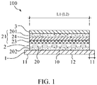
- FIG. 1 showing a schematic structural view of a flexible display device in accordance with an embodiment of the preset application.
- a flexible display device 100 of the present application includes a support backplate 1, a flexible display panel 2, and a flexible cover 3 bendable along a bending axis 10.
- the bending axis 10 is disposed longitudinally, while in another embodiment, an additional bending axis may be transversely disposed and may be perpendicular to and intersect the longitudinal bending axis 10.
- the support backplate 1 is disposed on a side of the flexible display panel 2 and is located on an outer side of the flexible display panel 2 with respect to a direction that the flexible display panel 2 is bent.
- the support backplate 1 includes a support area 12 for supporting the flexible display panel 2, and a plurality of extension areas 11 defined on opposite sides of the bending axis 10 and adjoining two sides of the support area 12.
- the support backplate 1 is made of stainless steel (SUS), glass, or a high-modulus material greater than 100 GPa (Pa).
- the flexible display panel 2 is laminated on the support area 12 of the support backplate 1.
- a functional film layer 21 is disposed on a side of the flexible display panel 2 away from the support backplate 1.
- the functional film layer 21 includes a touch layer 23 or a polarizer layer 24, and an upper optical clear adhesive (OCA) layer 201 sequentially disposed on the flexible display panel 2.
- the flexible display panel 2 includes an organic light-emitting module 20, and a lower OCA layer 202 is disposed between the flexible display panel 2 and the support backplate 1.
- the organic light-emitting module 20 includes a plurality of organic light-emitting devices composed of general thin-film transistors and organic light-emitting materials, and their detailed structure is not described here.
- a first length L1 is defined between two sides of the flexible display panel 2, and is the same as a length of the support area 12. In other words, two opposite ends of each of film layers of the functional film layer 21 are flush with two opposite ends of the flexible display panel 2, respectively.
- the flexible cover 3 is laminated on the functional film layer 21. Specifically, the flexible cover 3 is disposed on a side of the functional film layer 21 away from the flexible display panel 2. A second length L2 is defined between two opposite ends of the flexible cover 3 and has the same length as the first length L1.
- the flexible cover 3 is provided to protect the flexible display panel 2.
- the bending axis 10 is located at a middle of the support backplate 1.
- the support backplate 1 has two extension areas 11 extending outward of two opposite ends of each of the flexible display panel 2 and the flexible cover 3. That is, the support backplate 1 is configured with a length difference with the flexible display panel 2, a length difference with the functional film layer 21, and a length difference with the flexible cover 3.
- the length difference is a sum of lengths of the two extension areas 11 of the support backplate 1.
- FIG. 2 showing a schematic structural view of a flexible display device 100 in a bent state in accordance with an embodiment of the preset application, wherein layer structures of the flexible display panel 2 and the functional film layer 21 are omitted to be shown in FIG. 2 .
- each of the support backplate 1, the flexible display panel 2, and the flexible cover 3 includes a bending area corresponding to each other and a non-bending area corresponding to each other.
- a difference value between a length of the support backplate 1 and a length i.e.
- the first length LI) of the flexible display panel 2 in a direction perpendicular to the bending axis 10 is greater than or equal to a first threshold.
- the first threshold is defined as ⁇ (T-t1), wherein ⁇ is Pi, T is an entire thickness of the flexible display device 100, and t1 is a thickness of the flexible display panel 2 (as shown in FIG. 2 ).
- the flexible display panel 2 has a bending radius designated as r'
- the bending area of the support backplate 1 has a bending radius designated as R
- the non-bending area has a length designated as a.
- a difference value i.e.
- a difference value between the length of the support backplate 1 and a length of the functional film layer 21 in the direction perpendicular to the bending axis is greater than or equal to a second threshold.
- the second threshold is defined as ⁇ (T-t2), wherein ⁇ is Pi, T is the entire thickness of the flexible display device 100, and t2 is a thickness of the functional film layer 21 (as shown in FIG. 2 ).
- a difference value between the length of the support backplate 1 and a length of the flexible cover 3 in the direction perpendicular to the bending axis is greater than or equal to a third threshold.
- the third threshold is defined as ⁇ (T-t3), wherein ⁇ is Pi, T is the entire thickness of the flexible display device 100, and t3 is a thickness of the flexible cover 3.
- the flexible cover 3 has a bending radius designated as r, the bending area of the support backplate 1 has a bending radius designated as R, and the non-bending area has a length designated as a.
- a difference value i.e.
- the support backplate 1 is configured with a length difference with the flexible display panel 2, a length difference with the functional film layer 21, and a length difference with the flexible cover 3, respectively. That is, in a condition that a total length of the two extension areas 11 of the support backplate 1 is greater than or equal to the first threshold, the second threshold, or the third threshold, outer edges of a device can be flush with two opposite ends of each of the flexible cover 3, the flexible display panel 2, and the functional film layer 21 in the bent state, thereby overcoming a problem of a device likely to have sheared edges due to differences between inner and outer radiuses of the device in the bent state.
- FIG. 3 shows a schematic plan view of a flexible display device in accordance with an embodiment of the preset application.
- the support backplate 1 includes a plurality of extension areas surrounding the flexible display panel 2 and the flexible cover 3. A total length of the extension areas 11 in a same axial direction is greater than or equal to the first threshold, the second threshold, and the third threshold.
- the support backplate 1 is made of a dark opaque material, such as a black material is used for the entire support backplate 1. By providing the support backplate 1 made of a black material, a possibility of causing light leakage at edges due to a stack structure of the flexible display device 100 may be effectively avoided.
- FIG. 4 is another schematic structural view of a flexible display device in accordance with an embodiment of the preset application.
- the present application further provides flexible display equipment 101 including the flexible display panel 100 in accordance with any embodiment as described above, wherein the detailed structure of the flexible display device 100 is not described here.
- an encapsulation layer 14 is further provided around the flexible display device 100 to prevent external moisture and oxygen from entering.
- the flexible display device of the present application is provided with the support area and the extension areas defined on opposite sides of the bending axis and adjoining two sides of the support area. In this manner, when the flexible display device is in an expanded state, a difference value between a length of the support backplate and each of lengths of the flexible display panel, the functional film layer, and the flexible cover in a direction perpendicular to the bending axis is greater than or equal to a first threshold defined as n (T-t1), a second threshold defined as n (T-t2), and a third threshold defined as ⁇ (T-t3), respectively.
- edges of the two extension areas of the support backplate are flush with two opposite sides of each of the flexible display panel, the functional film layer, and the flexible cover, respectively, thereby effectively improving accuracy in assembling the device and reducing the risk of squeezing the flexible cover or a display module on an inner side when bending.
- a sheared edge between an inner screen body and an outer casing i.e.
Landscapes
- Physics & Mathematics (AREA)
- Devices For Indicating Variable Information By Combining Individual Elements (AREA)
- Optics & Photonics (AREA)
- General Physics & Mathematics (AREA)
- Engineering & Computer Science (AREA)
- Theoretical Computer Science (AREA)
- Electroluminescent Light Sources (AREA)
Abstract
Description
- The present invention relates to a technical field of displays, and particularly to, a flexible display device.
- Currently, foldable flexible organic light-emitting diode (OLED) display devices have been put on the market, facilitating simple and convenient lives.
- Foldable flexible OLED display devices are receiving widespread attention. Reliability and durability of display devices are key factors to determine whether the devices can quickly grab the market. General foldable flexible display devices include flexible covers, adhesives, functional layers, flexible display devices, adhesives, and supporting materials from top to bottom. The supporting materials are rigid materials. Each of thin-film layers has a certain thickness. In a situation that stack structures bend inward, edges of devices will inevitably be sheared due to differences between inner and outer radiuses. That is, after bending, edges of the thin-film layers are not flush with each other, thereby easily resulting in peeling of the thin-film layers. Furthermore, screen bodies and other structures are assembled with outermost supporting material layers as a reference base. As a result, materials such as flexible covers on insides of display devices will be subject to compressive stress from structural casings (i.e. supporting materials) on outer sides, causing unnecessary deformation and increasing the risk of peeling of components. Therefore, OLED screens including flexible and rigid materials need to be accurately assembled with structural casings to minimize stress on the screens, reduce the risk of screen peeling, and maintain and extend reliability of the product.
- An object of the present invention is to provide a flexible display device including a device casing having outer edges flush with outer edges of inner film layer structures in a bent state, thereby to improve assembly accuracy, reduce the risk of peeling of components, and ensure a product lifespan.
- In order to achieve the above-mentioned object, the present applications provides a flexible display device, comprising a flexible display panel bendable along a bending axis; a support backplate disposed on a side of the flexible display panel and located on an outer side of the flexible display panel with respect to a direction that the flexible display panel is bent, wherein the support backplate comprises a support area for supporting the flexible display panel, and a plurality of extension areas defined on opposite sides of the bending axis and adjoining two sides of the support area; wherein when the flexible display device is in an expanded state, a difference value between a length of the support backplate and a length of the flexible display panel in a direction perpendicular to the bending axis is greater than or equal to a first threshold
- Further, the first threshold is defined as π (T-t1), wherein π is Pi, T is an entire thickness of the flexible display device, and t1 is a thickness of the flexible display panel.
- Further, the flexible display device further comprises a functional film layer disposed on a side of the flexible display panel away from the support backplate, wherein when the flexible display device is in the expanded state, a difference value between the length of the support backplate and a length of the functional film layer in the direction perpendicular to the bending axis is greater than or equal to a second threshold.
- Further, the second threshold is defined as π (T-t2), wherein π is Pi, T is an entire thickness of the flexible display device, and t2 is a thickness of the functional film layer.
- Further, the functional film layer comprises at least one of a touch layer and a polarizer layer.
- Further, the flexible display device further comprises a flexible cover disposed on a side of the functional film layer away from the flexible display panel, wherein when the flexible display device is in the expanded state, a difference value between the length of the support backplate and a length of the flexible cover in the direction perpendicular to the bending axis is greater than or equal to a third threshold.
- Further, the third threshold is defined as π(T-t3), wherein π is Pi, T is an entire thickness of the flexible display device, and t3 is a thickness of the flexible cover.
- Further, each of the extension areas of the support backplate comprises an edge flush with opposite sides of the flexible display panel and the flexible cover, respectively, when the flexible display device is in a bent state.
- Further, the support backplate is made of a dark opaque material.
- Further, the support backplate is located at two opposite sides of the bending axis, and each of the extension areas adjoining the two sides of the support area has a same length.
- The present application further provides a flexible display device, comprising a flexible display panel bendable along a bending axis; a support backplate disposed on a side of the flexible display panel and located on an outer side of the flexible display panel with respect to a direction that the flexible display panel is bent, wherein the support backplate comprises a support area for supporting the flexible display panel, and a plurality of extension areas defined on opposite sides of the bending axis and adjoining two sides of the support area; a functional film layer disposed on a side of the flexible display panel away from the support backplate; and a flexible cover disposed on a side of the functional film layer away from the flexible display panel; wherein when the flexible display device is in an expanded state, in a direction perpendicular to the bending axis, a difference value between a length of the support backplate and a length of the flexible display panel is greater than or equal to a first threshold, a difference value between the length of the support backplate and a length of the functional film layer is greater than or equal to a second threshold, and a difference value between the length of the support backplate and a length of the flexible cover is greater than or equal to a third threshold.
- The flexible display device of the present application is provided with the support area and the extension areas defined on opposite sides of the bending axis and adjoining two sides of the support area. In this manner, when the flexible display device is in an expanded state, a difference value between a length of the support backplate and each of lengths of the flexible display panel, the functional film layer, and the flexible cover in a direction perpendicular to the bending axis is greater than or equal to a first threshold defined as n (T-t1), a second threshold defined as n (T-t2), and a third threshold defined as π(T-t3), respectively. Based on the flexible display device, in the bent state, edges of the two extension areas of the support backplate are flush with two opposite sides of each of the flexible display panel, the functional film layer, and the flexible cover, respectively, thereby effectively improving accuracy in assembling the device and reducing the risk of squeezing the flexible cover or a display module on an inner side when bending. On the other hand, based on the flexible display device, a sheared edge between an inner screen body and an outer casing (i.e. support backplate) of the device can be minimized, a capability to resist an external impact on the screen body can be increased, and light leakage at edges can be prevented, thereby effectively overcoming problems that conventional flexible display devices have poor assembly accuracy, internal components are prone to be squeezed when bending, film layers are likely to peel off, and display performance and lifespan of devices are adversely affected.
-
-
FIG. 1 is a schematic structural view of a flexible display device in accordance with an embodiment of the preset application. -
FIG. 2 is a schematic structural view showing a flexible display device in a bent state in accordance with an embodiment of the preset application. -
FIG. 3 is a schematic plan view of a flexible display device in accordance with an embodiment of the preset application. -
FIG. 4 is another schematic structural view of a flexible display device in accordance with an embodiment of the preset application. - The following embodiments are referring to the accompanying drawings for exemplifying specific implementable embodiments of the present invention. Directional terms described by the present invention, such as upper, lower, front, back, left, right, inner, outer, side, etc., are only directions by referring to the accompanying drawings, and thus the used directional terms are used to describe and understand the present invention, but the present invention is not limited thereto.
- The present application relates to a flexible display device, and particularly to a flexible display device capable of being self-luminous using organic light-emitting materials and being bendable to deform in a bent state or an expended state. The flexible display device of the present application can provide users with various usage patterns, including transformation of small-sized mobile phones or large-sized tablets by bending, and product reliability of the display device will not be affected due to bending.
- Please refer to
FIG. 1 showing a schematic structural view of a flexible display device in accordance with an embodiment of the preset application. Aflexible display device 100 of the present application includes asupport backplate 1, aflexible display panel 2, and aflexible cover 3 bendable along abending axis 10. It should be noted that, in this embodiment, thebending axis 10 is disposed longitudinally, while in another embodiment, an additional bending axis may be transversely disposed and may be perpendicular to and intersect thelongitudinal bending axis 10. Thesupport backplate 1 is disposed on a side of theflexible display panel 2 and is located on an outer side of theflexible display panel 2 with respect to a direction that theflexible display panel 2 is bent. Thesupport backplate 1 includes asupport area 12 for supporting theflexible display panel 2, and a plurality ofextension areas 11 defined on opposite sides of thebending axis 10 and adjoining two sides of thesupport area 12. In this embodiment, thesupport backplate 1 is made of stainless steel (SUS), glass, or a high-modulus material greater than 100 GPa (Pa). - As shown in
FIG. 1 , theflexible display panel 2 is laminated on thesupport area 12 of thesupport backplate 1. Afunctional film layer 21 is disposed on a side of theflexible display panel 2 away from thesupport backplate 1. Thefunctional film layer 21 includes atouch layer 23 or apolarizer layer 24, and an upper optical clear adhesive (OCA)layer 201 sequentially disposed on theflexible display panel 2. Theflexible display panel 2 includes an organic light-emitting module 20, and alower OCA layer 202 is disposed between theflexible display panel 2 and thesupport backplate 1. In this embodiment, the organic light-emitting module 20 includes a plurality of organic light-emitting devices composed of general thin-film transistors and organic light-emitting materials, and their detailed structure is not described here. In addition, most functions and structures of thetouch layer 23 and thepolarizer layer 24 are the same as those of conventional techniques, and will not be described here. Specifically, a first length L1 is defined between two sides of theflexible display panel 2, and is the same as a length of thesupport area 12. In other words, two opposite ends of each of film layers of thefunctional film layer 21 are flush with two opposite ends of theflexible display panel 2, respectively. - Please continue referring to
FIG. 1 . Theflexible cover 3 is laminated on thefunctional film layer 21. Specifically, theflexible cover 3 is disposed on a side of thefunctional film layer 21 away from theflexible display panel 2. A second length L2 is defined between two opposite ends of theflexible cover 3 and has the same length as the first length L1. Theflexible cover 3 is provided to protect theflexible display panel 2. Furthermore, in this embodiment, thebending axis 10 is located at a middle of thesupport backplate 1. As shown inFIG. 1 , thesupport backplate 1 has twoextension areas 11 extending outward of two opposite ends of each of theflexible display panel 2 and theflexible cover 3. That is, thesupport backplate 1 is configured with a length difference with theflexible display panel 2, a length difference with thefunctional film layer 21, and a length difference with theflexible cover 3. The length difference is a sum of lengths of the twoextension areas 11 of thesupport backplate 1. - Please refer to
FIG. 2 showing a schematic structural view of aflexible display device 100 in a bent state in accordance with an embodiment of the preset application, wherein layer structures of theflexible display panel 2 and thefunctional film layer 21 are omitted to be shown inFIG. 2 . Specifically, each of thesupport backplate 1, theflexible display panel 2, and theflexible cover 3 includes a bending area corresponding to each other and a non-bending area corresponding to each other. Particularly, when theflexible display device 100 is in an expanded state (as shown inFIGs. 1 and3 ), a difference value between a length of thesupport backplate 1 and a length (i.e. the first length LI) of theflexible display panel 2 in a direction perpendicular to the bendingaxis 10 is greater than or equal to a first threshold. In this embodiment, the first threshold is defined as π(T-t1), wherein π is Pi, T is an entire thickness of theflexible display device 100, and t1 is a thickness of the flexible display panel 2 (as shown inFIG. 2 ). Specifically, theflexible display panel 2 has a bending radius designated as r', the bending area of thesupport backplate 1 has a bending radius designated as R, and the non-bending area has a length designated as a. In this embodiment, a difference value (i.e. a total length of the two extension areas 11) between a length of thesupport backplate 1 located on an outer side of the flexible display device and a length of theflexible display panel 2 located on an inner side of the flexible display device is defined by an equationM = (2a+πR)-(2a+πr')=π(R-r')= π(T-t1), so that the first threshold π(T-t) can be proved by the equation. - Likewise, in another embodiment, when the
flexible display device 100 is in the expanded state, a difference value between the length of thesupport backplate 1 and a length of thefunctional film layer 21 in the direction perpendicular to the bending axis is greater than or equal to a second threshold. Specifically, the second threshold is defined as π (T-t2), wherein π is Pi, T is the entire thickness of theflexible display device 100, and t2 is a thickness of the functional film layer 21 (as shown inFIG. 2 ). - In another embodiment, when the
flexible display device 100 is in the expanded state, a difference value between the length of thesupport backplate 1 and a length of theflexible cover 3 in the direction perpendicular to the bending axis is greater than or equal to a third threshold. Specifically, the third threshold is defined as π (T-t3), wherein π is Pi, T is the entire thickness of theflexible display device 100, and t3 is a thickness of theflexible cover 3. As shown inFIG. 2 , theflexible cover 3 has a bending radius designated as r, the bending area of thesupport backplate 1 has a bending radius designated as R, and the non-bending area has a length designated as a. In this embodiment, a difference value (i.e. a total length of the two extension areas 11) between the length of thesupport backplate 1 located on the outer side of the flexible display device and a length of theflexible cover 3 located on an inner side of the flexible display device is defined by an equation M = (2a+πR)-(2a+πr)=π(R-r)=π(T-t3), so that the second threshold π (T-t3) can be proved by the equation. - As described above, the
support backplate 1 is configured with a length difference with theflexible display panel 2, a length difference with thefunctional film layer 21, and a length difference with theflexible cover 3, respectively. That is, in a condition that a total length of the twoextension areas 11 of thesupport backplate 1 is greater than or equal to the first threshold, the second threshold, or the third threshold, outer edges of a device can be flush with two opposite ends of each of theflexible cover 3, theflexible display panel 2, and thefunctional film layer 21 in the bent state, thereby overcoming a problem of a device likely to have sheared edges due to differences between inner and outer radiuses of the device in the bent state. -
FIG. 3 shows a schematic plan view of a flexible display device in accordance with an embodiment of the preset application. As shown inFIG. 3 , thesupport backplate 1 includes a plurality of extension areas surrounding theflexible display panel 2 and theflexible cover 3. A total length of theextension areas 11 in a same axial direction is greater than or equal to the first threshold, the second threshold, and the third threshold. Furthermore, thesupport backplate 1 is made of a dark opaque material, such as a black material is used for theentire support backplate 1. By providing thesupport backplate 1 made of a black material, a possibility of causing light leakage at edges due to a stack structure of theflexible display device 100 may be effectively avoided. -
FIG. 4 is another schematic structural view of a flexible display device in accordance with an embodiment of the preset application. As shown inFIG. 4 , the present application further providesflexible display equipment 101 including theflexible display panel 100 in accordance with any embodiment as described above, wherein the detailed structure of theflexible display device 100 is not described here. As shown inFIG. 4 , anencapsulation layer 14 is further provided around theflexible display device 100 to prevent external moisture and oxygen from entering. - The flexible display device of the present application is provided with the support area and the extension areas defined on opposite sides of the bending axis and adjoining two sides of the support area. In this manner, when the flexible display device is in an expanded state, a difference value between a length of the support backplate and each of lengths of the flexible display panel, the functional film layer, and the flexible cover in a direction perpendicular to the bending axis is greater than or equal to a first threshold defined as n (T-t1), a second threshold defined as n (T-t2), and a third threshold defined as π(T-t3), respectively. Based on the flexible display device, in the bent state, edges of the two extension areas of the support backplate are flush with two opposite sides of each of the flexible display panel, the functional film layer, and the flexible cover, respectively, thereby effectively improving accuracy in assembling the device and reducing the risk of squeezing the flexible cover or a display module on an inner side when bending. On the other hand, based on the flexible display device, a sheared edge between an inner screen body and an outer casing (i.e. support backplate) of the device can be minimized, a capability to resist an external impact on the screen body can be increased, and light leakage at edges can be prevented, thereby effectively overcoming problems that conventional flexible display devices have poor assembly accuracy, internal components are prone to be squeezed when bending, film layers are likely to peel off, and display performance and lifespan of devices are adversely affected.
- Accordingly, although the present invention has been disclosed as a preferred embodiment, it is not intended to limit the present invention. Those skilled in the art without departing from the scope of the present invention may make various changes or modifications, and thus the scope of the present invention should be after the appended claims and their equivalents.
Claims (16)
- A flexible display device, comprising:a flexible display panel bendable along a bending axis; anda support backplate disposed on a side of the flexible display panel and located on an outer side of the flexible display panel with respect to a direction that the flexible display panel is bent, wherein the support backplate comprises a support area for supporting the flexible display panel, and a plurality of extension areas defined on opposite sides of the bending axis and adjoining two sides of the support area;wherein when the flexible display device is in an expanded state, a difference value between a length of the support backplate and a length of the flexible display panel in a direction perpendicular to the bending axis is greater than or equal to a first threshold.
- The flexible display device of claim 1, wherein the first threshold is defined as π(T-t1), wherein π is Pi, T is an entire thickness of the flexible display device, and t1 is a thickness of the flexible display panel.
- The flexible display device of claim 1, further comprising a functional film layer disposed on a side of the flexible display panel away from the support backplate, wherein when the flexible display device is in the expanded state, a difference value between the length of the support backplate and a length of the functional film layer in the direction perpendicular to the bending axis is greater than or equal to a second threshold.
- The flexible display device of claim 3, wherein the second threshold is defined as π (T-t2), wherein π is Pi, T is an entire thickness of the flexible display device, and t2 is a thickness of the functional film layer.
- The flexible display device of claim 4, wherein the functional film layer comprises at least one of a touch layer and a polarizer layer.
- The flexible display device of claim 1, further comprising a flexible cover disposed on a side of the functional film layer away from the flexible display panel, wherein when the flexible display device is in the expanded state, a difference value between the length of the support backplate and a length of the flexible cover in the direction perpendicular to the bending axis is greater than or equal to a third threshold.
- The flexible display device of claim 6, wherein the third threshold is defined as π(T-t3), wherein π is Pi, T is an entire thickness of the flexible display device, and t3 is a thickness of the flexible cover.
- The flexible display device of claim 6, wherein each of the extension areas of the support backplate comprises an edge flush with opposite sides of the flexible display panel and the flexible cover, respectively, when the flexible display device is in a bent state.
- The flexible display device of claim 1, wherein the support backplate is made of a dark opaque material.
- The flexible display device of claim 1, wherein the support backplate is located across the opposite sides of the bending axis, and each of the extension areas adjoining the two sides of the support area has a same length.
- A flexible display device, comprising:a flexible display panel bendable along a bending axis;a support backplate disposed on a side of the flexible display panel and located on an outer side of the flexible display panel with respect to a direction that the flexible display panel is bent, wherein the support backplate comprises a support area for supporting the flexible display panel, and a plurality of extension areas defined on opposite sides of the bending axis and adjoining two sides of the support area;a functional film layer disposed on a side of the flexible display panel away from the support backplate; anda flexible cover disposed on a side of the functional film layer away from the flexible display panel;wherein when the flexible display device is in an expanded state, in a direction perpendicular to the bending axis, a difference value between a length of the support backplate and a length of the flexible display panel is greater than or equal to a first threshold, a difference value between the length of the support backplate and a length of the functional film layer is greater than or equal to a second threshold, and a difference value between the length of the support backplate and a length of the flexible cover is greater than or equal to a third threshold.
- The flexible display device of claim 11, wherein the first threshold is defined as π (T-t1), wherein π is Pi, T is an entire thickness of the flexible display device, and t1 is a thickness of the flexible display panel.
- The flexible display device of claim 11, wherein the second threshold is defined as π (T-t2), wherein π is Pi, T is an entire thickness of the flexible display device, and t2 is a thickness of the functional film layer.
- The flexible display device of claim 11, wherein the third threshold is defined as π (T-t3), wherein π is Pi, T is an entire thickness of the flexible display device, and t3 is a thickness of the flexible cover.
- The flexible display device of claim 11, wherein the functional film layer comprises at least one of a touch layer and a polarizer layer.
- The flexible display device of claim 11, wherein the support backplate is located at two opposite sides of the bending axis, and each of the extension areas adjoining the two sides of the support area has a same length.
Applications Claiming Priority (2)
| Application Number | Priority Date | Filing Date | Title |
|---|---|---|---|
| CN201911300318.0A CN111063259A (en) | 2019-12-17 | 2019-12-17 | Flexible display device |
| PCT/CN2020/070278 WO2021120342A1 (en) | 2019-12-17 | 2020-01-03 | Flexible display device |
Publications (2)
| Publication Number | Publication Date |
|---|---|
| EP4080490A1 true EP4080490A1 (en) | 2022-10-26 |
| EP4080490A4 EP4080490A4 (en) | 2023-12-20 |
Family
ID=70301948
Family Applications (1)
| Application Number | Title | Priority Date | Filing Date |
|---|---|---|---|
| EP20725765.0A Pending EP4080490A4 (en) | 2019-12-17 | 2020-01-03 | FLEXIBLE DISPLAY DEVICE |
Country Status (4)
| Country | Link |
|---|---|
| US (1) | US11575104B2 (en) |
| EP (1) | EP4080490A4 (en) |
| CN (1) | CN111063259A (en) |
| WO (1) | WO2021120342A1 (en) |
Families Citing this family (2)
| Publication number | Priority date | Publication date | Assignee | Title |
|---|---|---|---|---|
| CN111710246A (en) * | 2020-07-20 | 2020-09-25 | 京东方科技集团股份有限公司 | A curved display screen, a preparation method thereof, and a display device |
| CN111785174A (en) * | 2020-08-07 | 2020-10-16 | 京东方科技集团股份有限公司 | Support structure of flexible panel, method for making the same, and flexible display device |
Family Cites Families (17)
| Publication number | Priority date | Publication date | Assignee | Title |
|---|---|---|---|---|
| US6953735B2 (en) * | 2001-12-28 | 2005-10-11 | Semiconductor Energy Laboratory Co., Ltd. | Method for fabricating a semiconductor device by transferring a layer to a support with curvature |
| KR102206376B1 (en) * | 2013-09-24 | 2021-01-22 | 삼성디스플레이 주식회사 | Cover window for display device, display device comprising the same |
| KR101669026B1 (en) * | 2013-10-10 | 2016-10-26 | 삼성디스플레이 주식회사 | Window member in a bended display device, method of manufacturing a window member of a bended display device, and bended display device having the same |
| US10090490B2 (en) | 2014-12-02 | 2018-10-02 | Sharp Kabushiki Kaisha | Method of producing curved display panel |
| CN105513497B (en) * | 2015-12-31 | 2019-11-05 | 京东方科技集团股份有限公司 | A kind of flexible apparatus |
| JP6857477B2 (en) * | 2016-09-30 | 2021-04-14 | 日東電工株式会社 | Organic EL display device |
| CN108665804A (en) | 2017-03-31 | 2018-10-16 | 元太科技工业股份有限公司 | Foldable electronic paper display device and manufacturing method thereof |
| CN107195253B (en) * | 2017-07-26 | 2020-08-25 | 武汉天马微电子有限公司 | Foldable flexible display device |
| CN109509402B (en) * | 2017-09-14 | 2022-03-18 | 广州国显科技有限公司 | Flexible display device |
| CN109961692A (en) * | 2017-12-26 | 2019-07-02 | 昆山维信诺科技有限公司 | Flexible display device and preparation method thereof |
| CN108831301B (en) * | 2018-06-15 | 2021-04-27 | 云谷(固安)科技有限公司 | Flexible display screen and flexible display device |
| CN108877524A (en) * | 2018-06-29 | 2018-11-23 | 武汉华星光电半导体显示技术有限公司 | Flexible OLED display |
| CN108898957B (en) * | 2018-08-30 | 2022-03-08 | 武汉华星光电半导体显示技术有限公司 | Foldable display device |
| CN109599503B (en) * | 2019-01-04 | 2021-10-08 | 京东方科技集团股份有限公司 | a display device |
| CN110277023A (en) * | 2019-05-30 | 2019-09-24 | 武汉华星光电半导体显示技术有限公司 | Display panel and display device |
| CN110197620B (en) * | 2019-06-26 | 2021-06-29 | 云谷(固安)科技有限公司 | Flexible display module and flexible display device |
| CN110491298A (en) * | 2019-08-30 | 2019-11-22 | 武汉华星光电半导体显示技术有限公司 | Foldable display device |
-
2019
- 2019-12-17 CN CN201911300318.0A patent/CN111063259A/en active Pending
-
2020
- 2020-01-03 EP EP20725765.0A patent/EP4080490A4/en active Pending
- 2020-01-03 US US16/955,580 patent/US11575104B2/en active Active
- 2020-01-03 WO PCT/CN2020/070278 patent/WO2021120342A1/en not_active Ceased
Also Published As
| Publication number | Publication date |
|---|---|
| US20220140278A1 (en) | 2022-05-05 |
| EP4080490A4 (en) | 2023-12-20 |
| CN111063259A (en) | 2020-04-24 |
| WO2021120342A1 (en) | 2021-06-24 |
| US11575104B2 (en) | 2023-02-07 |
Similar Documents
| Publication | Publication Date | Title |
|---|---|---|
| CN211481295U (en) | Display modules and electronic equipment | |
| KR102519817B1 (en) | Display device | |
| CN114927059B (en) | Display device | |
| JP2023511896A (en) | Display modules and electronic devices | |
| KR102551050B1 (en) | Flexible display device | |
| US20230050666A1 (en) | Display Module and Electronic Device | |
| KR102206376B1 (en) | Cover window for display device, display device comprising the same | |
| US7652729B2 (en) | Display device including a flexible guide member between the display device and a cushioning member | |
| US11428998B2 (en) | Display device | |
| EP4020071B1 (en) | Foldable display screen and fabrication method therefor, and display device | |
| JP2004510186A (en) | Multi display device | |
| US20200333844A1 (en) | Flexible display device | |
| US7768591B2 (en) | Display panel module having an adhesive member between a casing and the display panel with a breathing structure having a capillary produced in the adhesive member | |
| US11575104B2 (en) | Flexible display device | |
| US12216499B2 (en) | Display device | |
| US20050254261A1 (en) | Backlight module | |
| US10831241B1 (en) | Portable information device | |
| US20120229390A1 (en) | Mobile device | |
| CN209859506U (en) | Flexible display device | |
| US11800658B2 (en) | Display device | |
| CN211557295U (en) | Display screen and electronic equipment | |
| CN218939156U (en) | Display screen and electronic equipment | |
| KR20250016652A (en) | Display device and method of manufacturing display device | |
| KR20240043836A (en) | Display device | |
| US20080074579A1 (en) | Backlight module with reflective plate and liquid crystal display employing same |
Legal Events
| Date | Code | Title | Description |
|---|---|---|---|
| STAA | Information on the status of an ep patent application or granted ep patent |
Free format text: STATUS: UNKNOWN |
|
| STAA | Information on the status of an ep patent application or granted ep patent |
Free format text: STATUS: THE INTERNATIONAL PUBLICATION HAS BEEN MADE |
|
| PUAI | Public reference made under article 153(3) epc to a published international application that has entered the european phase |
Free format text: ORIGINAL CODE: 0009012 |
|
| STAA | Information on the status of an ep patent application or granted ep patent |
Free format text: STATUS: REQUEST FOR EXAMINATION WAS MADE |
|
| 17P | Request for examination filed |
Effective date: 20200525 |
|
| AK | Designated contracting states |
Kind code of ref document: A1 Designated state(s): AL AT BE BG CH CY CZ DE DK EE ES FI FR GB GR HR HU IE IS IT LI LT LU LV MC MK MT NL NO PL PT RO RS SE SI SK SM TR |
|
| DAV | Request for validation of the european patent (deleted) | ||
| DAX | Request for extension of the european patent (deleted) | ||
| REG | Reference to a national code |
Ref country code: DE Ref legal event code: R079 Free format text: PREVIOUS MAIN CLASS: G09F0009300000 Ipc: B32B0003020000 |
|
| A4 | Supplementary search report drawn up and despatched |
Effective date: 20231116 |
|
| RIC1 | Information provided on ipc code assigned before grant |
Ipc: B32B 7/023 20190101ALI20231110BHEP Ipc: B32B 3/08 20060101ALI20231110BHEP Ipc: B32B 3/02 20060101AFI20231110BHEP |