EP4080447A1 - Determination system, determination method, computer program, and authentication system - Google Patents
Determination system, determination method, computer program, and authentication system Download PDFInfo
- Publication number
- EP4080447A1 EP4080447A1 EP19956374.3A EP19956374A EP4080447A1 EP 4080447 A1 EP4080447 A1 EP 4080447A1 EP 19956374 A EP19956374 A EP 19956374A EP 4080447 A1 EP4080447 A1 EP 4080447A1
- Authority
- EP
- European Patent Office
- Prior art keywords
- target person
- marker
- unit
- image
- living body
- Prior art date
- Legal status (The legal status is an assumption and is not a legal conclusion. Google has not performed a legal analysis and makes no representation as to the accuracy of the status listed.)
- Withdrawn
Links
Images




Classifications
-
- G—PHYSICS
- G06—COMPUTING OR CALCULATING; COUNTING
- G06V—IMAGE OR VIDEO RECOGNITION OR UNDERSTANDING
- G06V40/00—Recognition of biometric, human-related or animal-related patterns in image or video data
- G06V40/40—Spoof detection, e.g. liveness detection
-
- G—PHYSICS
- G06—COMPUTING OR CALCULATING; COUNTING
- G06V—IMAGE OR VIDEO RECOGNITION OR UNDERSTANDING
- G06V40/00—Recognition of biometric, human-related or animal-related patterns in image or video data
- G06V40/40—Spoof detection, e.g. liveness detection
- G06V40/45—Detection of the body part being alive
-
- G—PHYSICS
- G06—COMPUTING OR CALCULATING; COUNTING
- G06F—ELECTRIC DIGITAL DATA PROCESSING
- G06F21/00—Security arrangements for protecting computers, components thereof, programs or data against unauthorised activity
- G06F21/30—Authentication, i.e. establishing the identity or authorisation of security principals
- G06F21/31—User authentication
- G06F21/32—User authentication using biometric data, e.g. fingerprints, iris scans or voiceprints
-
- G—PHYSICS
- G06—COMPUTING OR CALCULATING; COUNTING
- G06T—IMAGE DATA PROCESSING OR GENERATION, IN GENERAL
- G06T7/00—Image analysis
- G06T7/70—Determining position or orientation of objects or cameras
-
- G—PHYSICS
- G06—COMPUTING OR CALCULATING; COUNTING
- G06V—IMAGE OR VIDEO RECOGNITION OR UNDERSTANDING
- G06V10/00—Arrangements for image or video recognition or understanding
- G06V10/20—Image preprocessing
- G06V10/22—Image preprocessing by selection of a specific region containing or referencing a pattern; Locating or processing of specific regions to guide the detection or recognition
- G06V10/225—Image preprocessing by selection of a specific region containing or referencing a pattern; Locating or processing of specific regions to guide the detection or recognition based on a marking or identifier characterising the area
-
- G—PHYSICS
- G06—COMPUTING OR CALCULATING; COUNTING
- G06V—IMAGE OR VIDEO RECOGNITION OR UNDERSTANDING
- G06V40/00—Recognition of biometric, human-related or animal-related patterns in image or video data
- G06V40/10—Human or animal bodies, e.g. vehicle occupants or pedestrians; Body parts, e.g. hands
- G06V40/16—Human faces, e.g. facial parts, sketches or expressions
- G06V40/161—Detection; Localisation; Normalisation
-
- G—PHYSICS
- G06—COMPUTING OR CALCULATING; COUNTING
- G06V—IMAGE OR VIDEO RECOGNITION OR UNDERSTANDING
- G06V40/00—Recognition of biometric, human-related or animal-related patterns in image or video data
- G06V40/10—Human or animal bodies, e.g. vehicle occupants or pedestrians; Body parts, e.g. hands
- G06V40/16—Human faces, e.g. facial parts, sketches or expressions
- G06V40/172—Classification, e.g. identification
-
- G—PHYSICS
- G06—COMPUTING OR CALCULATING; COUNTING
- G06T—IMAGE DATA PROCESSING OR GENERATION, IN GENERAL
- G06T2207/00—Indexing scheme for image analysis or image enhancement
- G06T2207/10—Image acquisition modality
- G06T2207/10016—Video; Image sequence
-
- G—PHYSICS
- G06—COMPUTING OR CALCULATING; COUNTING
- G06T—IMAGE DATA PROCESSING OR GENERATION, IN GENERAL
- G06T2207/00—Indexing scheme for image analysis or image enhancement
- G06T2207/30—Subject of image; Context of image processing
- G06T2207/30196—Human being; Person
-
- G—PHYSICS
- G06—COMPUTING OR CALCULATING; COUNTING
- G06T—IMAGE DATA PROCESSING OR GENERATION, IN GENERAL
- G06T2207/00—Indexing scheme for image analysis or image enhancement
- G06T2207/30—Subject of image; Context of image processing
- G06T2207/30204—Marker
Definitions
- the present invention relates to a determination system, a determination method, a computer program, and an authentication system that make a determination related to a target person.
- Patent Literature 1 discloses a technique/technology of detecting spoofing by utilizing a difference between a biological distance and a non-biological distance.
- Patent Literature 2 discloses a technique/technology of detecting spoofing by comparing an image captured in a pupil of a subject with a particular image.
- Patent Literature 3 discloses a technique/technology of displaying a particular background image in an authentication place and of detecting spoofing by using brightness of a captured image.
- the present invention has been made in view of the above problems, and it is an example object of the present invention to provide a determination system, a determination method, a computer program, and an authentication apparatus that are configured accurately determine whether or not a target person is a living body.
- a determination system includes: a projection control unit that controls a projection unit to project a random marker within an angle of view of an imaging unit; an acquisition unit that obtains an image of a target person including the marker from the imaging unit; and a determination unit that determines whether or not the target person imaged by the imaging unit is a living body on the basis of a state of the marker included in the image.
- a determination method includes: controlling a projection unit to project a random marker within an angle of view of an imaging unit; obtaining an image of a target person including the marker from the imaging unit; and determining whether or not the target person imaged by the imaging unit is a living body on the basis of a state of the marker included in the image.
- a computer program operates a computer: to control a projection unit to project a random marker within an angle of view of an imaging unit; to obtain an image of a target person including the marker from the imaging unit; and to determine whether or not the target person imaged by the imaging unit is a living body on the basis of a state of the marker included in the image.
- An authentication system includes: a projection control unit that controls a projection unit to project a random marker within an angle of view of an imaging unit; an acquisition unit that obtains an image of a target person including the marker from the imaging unit; a determination unit that determines whether or not the target person imaged by the imaging unit is a living body on the basis of a state of the marker included in the image; and an execution unit that performs an authentication process on the target person when it is determined that the target person is a living body.
- the determination system the determination method, the computer program, and the authentication system in the respective aspects described above, it is possible to accurately determine whether or not a target person is a living body. This makes it possible to detect, for example, spoofing by a photograph or the like and to appropriately perform biometric authentication.
- FIG. 1 is a block diagram illustrating the functional configuration of the determination system according to the example embodiment.
- a determination system 10 is configured as an apparatus for determining whether or not a target person of an authentication process (in other words, an imaging target of a face image) is a living body.
- the determination system 10 includes, as processing blocks for realizing its function, a projection control unit 101, an image acquisition unit 102, and a living body determination unit 103.
- the projection control unit 101 is configured to control the operation of a projection unit that projects a marker (e.g., a projector 20 described later).
- the projection control unit 101 is allowed to control the projection unit to project a random marker so as to overlap a background of the target person or the target person.
- the projection control unit 101 for example, stores a plurality of types of markers in advance (specifically, markers with different colors, shapes, sizes, or the like) and selects one or more markers at random from among them to project. Alternatively, the projection control unit 101 may automatically generate and project a marker at each time.
- the image acquisition unit 102 is configured to obtain an image of the target person for whom it is determined whether or not to be a living body.
- the image acquisition unit 102 obtains an image of the target person including the marker projected by the projection control unit 101.
- the image acquisition unit 102 may also be configured to obtain a plurality of temporally continuous images (in other words, a moving image).
- the image obtained by image acquisition unit 102 is configured to be outputted to the living body determination unit 103
- the living body determination unit 103 determines whether or not the target person is a living body on the basis of the image obtained by the image acquisition unit 102. More specifically, the living body determining unit 103 determines whether the target person is actually in front of an imaging unit (e.g., a camera 30 described later) or "spoofing" by a photograph or the like is performed. The living body determination unit 103 determines whether or not the target person is a living body on the basis of a state of the marker included in the image of the target person (i.e., the marker projected by the projection control unit 101). A specific determination method in the living body determination unit 103 will be described in detail later. A result of the determination by the living body determining unit 103 is configured to be outputted to an external apparatus (e.g., an authentication apparatus 40 described later).
- an external apparatus e.g., an authentication apparatus 40 described later.
- FIG. 2 is a block diagram illustrating the hardware configuration of the determination system according to the example embodiment.
- the determination system 10 includes a CPU (Central Processing Unit) 11, a RAM (Random Access Memory) 12, a ROM (Read Only Memory) 13, and a storage apparatus 14.
- the determination system 10 may further include an input apparatus 15 and an output apparatus 16.
- the CPU 11, the RAM 12, the ROM 13, the storage apparatus 14, the input apparatus 15, and the output apparatus 16 are connected through a data bus 17.
- the CPU 11 reads a computer program.
- the CPU 11 is configured to read a computer program stored in at least one of the RAM 12, the ROM 13 and the storage apparatus 14.
- the CPU 11 may read a computer program stored by a computer readable recording medium by using a not-illustrated recording medium reading apparatus.
- the CPU 11 may obtain (i.e., read) a computer program from a not-illustrated apparatus that is located outside the determination system 10 through a network interface.
- the CPU 11 controls the RAM 12, the storage apparatus 14, the input apparatus 15, and the output apparatus 16 by executing the read computer program.
- a functional block for determining whether or not the target person is a living body is implemented in the CPU 11.
- the RAM 12 temporarily stores the computer program to be executed by the CPU 11.
- the RAM 12 temporarily stores the data that is temporarily used by the CPU 11 when the CPU 11 executes the computer program.
- the RAM 12 may be, for example, a D-RAM (Dynamic RAM).
- the ROM 13 stores the computer program to be executed by the CPU 11.
- the ROM 13 may otherwise store fixed data.
- the ROM 13 may be, for example, a P-ROM (Programmable ROM).
- the storage apparatus 14 stores the data that is stored for a long term by the determination system 10.
- the storage apparatus 14 may operate as a temporary storage apparatus of the CPU 11.
- the storage apparatus 14 may include, for example, at least one of a hard disk apparatus, a magneto-optical disk apparatus, an SSD (Solid State Drive), and a disk array apparatus.
- the input apparatus 15 is an apparatus that receives an input instruction from a user of the determination system 10.
- the input apparatus 15 may include, for example, at least one of a keyboard, a mouse, and a touch panel.
- the output apparatus 16 is an apparatus that outputs information about the determination system 10 to the outside.
- the output apparatus 16 may be a display apparatus (e.g., a display) that is configured to display the information about the determination system 10.
- FIG. 3 is a block diagram illustrating the overall configuration of the authentication system according to the example embodiment.
- an authentication system 1 is configured as a system for performing an authentication process that uses a face image of the target person (so-called face authentication).
- the authentication system 1 includes the determination system 10 described above, a projector 20, a camera 30, and an authentication apparatus 40.
- the projector 20 is configured to project a random marker in accordance with an instruction of the projection control unit 101 in the determination system 10.
- the projector 20 is disposed in a position in which the marker can be projected within an angle of view of the camera 30.
- the projector 20 may project the marker with visible light or invisible light such as near infrared light.
- the camera 30 is configured to capture an image of the target person of the authentication process (especially, an image around a face). Furthermore, the camera 30 is disposed in a position in which the marker projected from the projector 20 together with target person can be imaged. The image obtained by the camera 30 is configured to be outputted to the image acquisition unit 102 in the determination system 10.
- the camera 30 may be configured as a camera that is configured to image invisible light.
- the authentication apparatus 40 performs face authentication of the target person on the basis of the image captured by the camera 30.
- the authentication apparatus 40 is configured to perform the authentication process on the basis of a determination result of the determination system 10 (i.e., whether the target person is a living body).
- the use of the determination result of the determination system 10 in the authentication apparatus 40 will be described in detail later.
- the authentication apparatus 40 may be configured to perform biometric authentication other than the face authentication (e.g., iris authentication, etc.) in place of the face authentication. A detailed description of specific contents of the authentication process performed by the authentication apparatus 40 will be omitted here because the existing techniques can be adapted.
- the authentication apparatus 40 may be configured, for example, as a cloud.
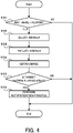
- FIG. 4 is a flow chart illustrating the flow of the operation of the authentication system according to the example embodiment.
- the authentication system 1 firstly determines whether or not there is a target person of the authentication process (step S101). Whether or not there is a target person can be determined, for example, by detecting the presence of an object within the angle of view of a camera. The presence of the target person may be detected by the camera 30 or another not-illustrated sensor or the like. Alternatively, the presence of the target person may be detected when there is a terminal operated by the target person.
- the step S101 NO
- the subsequent steps are omitted and a series of operation steps is ended. In this case, the step S101 may be restarted after a lapse of a predetermined period.
- the projection control unit 101 randomly selects a marker to be projected (step S102). Then, the projection control unit 101 controls the projector 20 to project the selected marker. At this time, the projection control unit 101 may specify a projection position of the marker. Specifically, the projection control unit 101 may give an instruction to project the marker on the background of the target person (in other words, a position that does not overlap the target person), or give an instruction to project the marker at a position that allows at least a partial overlap of the target person. When projecting the marker to overlap the target person, however, it is preferable to project it while avoiding the position of eyes so as not to give a dazzling feeling to the target person, or to project it with invisible light. Furthermore, an instruction may be given to project a plurality of markers at different positions.
- the image acquisition unit 102 obtains an image of the target person from the camera 30 (step S104). This image also includes the marker projected by the projector 20. When obtaining a moving image of the target person, the image acquisition unit 102 may continuously obtain images of the target person.
- the living body determination unit 103 determines whether or not the target person is a living body on the basis of the image of the target person obtained by the image acquisition unit 102 (step S105).
- the living body determination unit 103 determines whether or not the target person is a living body, depending on whether or not the marker included in the image of the target person is captured in an expected state. Specifically, the living body determination unit 103 determines that the target person is a living body when the state of the marker included in the image of the target person is as expected, and determines that the target person is not a living body when it is not as expected.
- the living body determination unit 103 determines whether or not the state of the marker is as expected, for example, by using at least one of a position, an angle, and a size of the marker.
- the living body determination unit 103 may determine whether or not the target person is a living body, by using a parameter other than the position, the angle and the size of the marker (e.g., color and shape, etc.).
- the living body determination unit 103 projects the marker to a wall in a condition where there is no target person in advance, and stores a captured image at that time as a reference image. In this way, it is possible to determine whether or not the state of the marker is as expected by comparing the marker with the reference image. More specifically, the living body determination unit 103 is configured to determine whether or not the target person is a living body on the basis of a degree of matching of (at least one of) the position, the angle, the size between the marker included in the image obtained by imaging the target person and the marker in the reference image.
- the existing method may be adopted, as appropriate, to the derivation of the degree of matching, but common template matching or pattern matching in an imaging process, such as, for example, a SSD (Sum Of Squared Difference) and a SAD (Sum of Absolute Difference), may be used.
- SSD Sum Of Squared Difference
- SAD Sum of Absolute Difference
- the authentication apparatus 40 When it is determined that the target person is a living body (the step S105: YES), the authentication apparatus 40 performs the authentication process (in this example, face authentication that uses a face image) on the target person (step S106). Specifically, the authentication apparatus 40 extracts a face area from the image of the target person and determines whether or not the face of the target person matches a face registered in advance. Incidentally, the face authentication may use the image of the target person as it is, or may use a feature quantity (e.g., brightness, etc.) extracted from the image of the target person. When the authentication process is ended, the authentication apparatus 40 outputs a result (e.g., "authentication OK" or "authentication NG").
- a result e.g., "authentication OK" or "authentication NG"
- the authentication apparatus 40 does not perform the face authentication (i.e., the step S106 is omitted).
- the target person is not a living body, for example, "spoofing" by a photograph or the like is suspected.
- the living body determination unit 103 may give a notice indicating that spoofing is performed. Specifically, the living body determining unit 103 may output a warning display or a warning sound to a system administrator or manager or the like.
- FIG. 5 is an image diagram illustrating an example of marker projection in normal times.
- FIG. 6 is an image diagram illustrating an example of marker projection in attack.
- FIG. 7A and FIG. 7B are comparative diagrams illustrating a difference between a captured image in normal times and a captured image in attack.
- a marker 200 projected from the projector 20 is projected on a background of the target person 500 (e.g., a wall behind the target person 500 or the like).
- a position relationship between the projector 20 and the background is known in advance, it is possible to accurately predict in what state the marker is projected on the background. For example, by projecting the marker on the background (e.g., a wall or the like) in advance without a target person and storing a captured image at that time as a reference image, it is possible to know the position relationship between the projector 20 and the background in advance.
- the marker 200 projected from the projector 20 is projected on the photograph of the target person 500.
- the marker 200 is projected at a position closer than expected, for example, the size of the marker 200 is smaller than that expected.
- FIG. 7A and FIG. 7B when comparing the images of the target person 500 captured in the situations of FIG. 5 and FIG. 6 described above, there is a clear difference in how the marker 200 appears. Specifically, when the target person 500 is a living body, as illustrated in FIG. 7A , the marker 200 appears in the captured image in an expected state. On the other hand, when the target person 500 is not a living body, as in FIG. 7B , the marker 200 appears in the captured image in an unexpected state (specifically, a state in which the marker 200 is projected to be smaller than that in FIG. 7A ). Thus, by analyzing how the marker 200 appears in the captured image, it is possible to accurately determine whether or not the target person 500 is a living body.
- the marker 200 is set to be a circle mark, but the shape of the marker is not particularly limited.
- the marker 200 may include more complex patterns or may include characters or the like.
- a plurality of markers 200 may be projected on the background of the target person. In this case, when at least one marker 200 of the projected markers 200 appears in the captured image in an unexpected state, it may be determined that the target person 500 is not a living body.
- FIG. 8A and FIG. 8B are comparative diagrams illustrating an example of projecting the marker to overlap the target person.
- the marker 200 may be projected to overlap the target person 500. Even in such a case, depending on whether or not the target person 500 is a living body, there is a clear difference in how the marker 200 appears in the captured image. Specifically, when the target person 500 is a living body, as in FIG. 8A , the marker 200 is distorted (or deviated) at a border part of the living body. Alternatively, even if the marker 200 is projected to overlap the target person 500 completely, the marker 200 is distorted to a greater or lesser extent due to the unevenness of the target person 500. On the other hand, when the target person 500 is not a living body (e.g., for a planar object such as a photograph), as in FIG.
- the marker 200 is not distorted. As descried above, by projecting the marker 200 to overlap the target person 500, it is possible to determine whether or not the target person 500 is a living body depending on whether or not the marker 200 is distorted in the captured image. Even when the marker 200 is distorted, if the distortion is unnatural, it may be determined that the target person 500 is not a living body.
- the projector 20 (i.e., a projection unit that projects the marker 200) may be provided independently of the determination system 10.
- the projector 20 may be configured to project the marker 200 manually (i.e., by an operation of an operator). In this way, it is possible to project the marker 200 at any timing of an operator.
- the determination system 10 may not include the projection control unit 101.
- the projection of the marker 200 may be started without the target person 500. Specifically, it may be determined whether or not there is the target person 500 after the marker 200 is projected, and when there is the target person 500, the image of the target person 500 may be obtained. In this way, the target person 500 can view the position of the marker 200 in advance (i.e., the target person 500 can confirm the position of the marker 200 before being imaged by the camera 30). Therefore, the target person 500 can adjust his or her own position in accordance with the position of the marker 200. For example, the target person 500 can adjust a standing position such that the marker 200 does not overlap the eyes.
- the marker 200 is projected, and it is determined whether or not the target person 500 is a living body. Therefore, it is possible to avoid, for example, an attack by "spoofing" that uses a photograph or the like.
- the marker 200 By utilizing the marker 200 as in the example embodiment, it is possible to avoid illegal authentication breakthrough by a relatively simple apparatus configuration. Furthermore, since a special action is not required of the target person 500, a burden on the target person 500 is not increased in the authentication process.
- a determination system described in Supplementary Note 1 is a determination system including: a projection control unit that controls a projection unit to project a random marker within an angle of view of an imaging unit; an acquisition unit that obtains an image of a target person including the marker from the imaging unit; and a determination unit that determines whether or not the target person imaged by the imaging unit is a living body on the basis of a state of the marker included in the image.
- a determination system described in Supplementary Note 2 is the determination system described in Supplementary Note 1, wherein the determination unit determines whether or not the target person imaged by the imaging unit is a living body on the basis of at least one of a position, an angle, and a size of the marker in the image.
- a determination system described in Supplementary Note 3 is the determination system described in Supplementary Note 1 or 2, wherein the determination unit gives a notice indicating that spoofing is performed when it is determined that the target person imaged by the imaging unit is not a living body.
- a determination system described in Supplementary Note 4 is the determination system described in any one of Supplementary Notes 1 to 3, wherein the projection control unit allows the marker to be projected in a background part of the target person.
- a determination system described in Supplementary Note 5 is the determination system described in any one of Supplementary Notes 1 to 3, wherein the projection control unit allows the marker to be projected so as to at least partially overlap the target person.
- a determination system described in Supplementary Note 6 is the determination system described in any one of Supplementary Notes 1 to 5, wherein the projection control unit allows the marker to be projected with invisible light.
- a determination system described in Supplementary Note 7 is the determination system described in any one of Supplementary Notes 1 to 6, wherein the acquisition unit obtains a plurality of temporally continuous images from the imaging unit, and the determination unit determines whether or not the target person imaged by the imaging unit is a living body on the basis of a state of the marker included in the plurality of images.
- a determination method described in Supplementary Note 8 is A determination method including: controlling a projection unit to project a random marker within an angle of view of an imaging unit; obtaining an image of a target person including the marker from the imaging unit; and determining whether or not the target person imaged by the imaging unit is a living body on the basis of a state of the marker included in the image.
- a computer program described in Supplementary Note 9 is a computer program that operates a computer: to control a projection unit to project a random marker within an angle of view of an imaging unit; to obtain an image of a target person including the marker from the imaging unit; and to determine whether or not the target person imaged by the imaging unit is a living body on the basis of a state of the marker included in the image.
- An authentication system described in Supplementary Note 10 is an authentication system including: a projection control unit that controls a projection unit to project a random marker within an angle of view of an imaging unit; an acquisition unit that obtains an image of a target person including the marker from the imaging unit; a determination unit that determines whether or not the target person imaged by the imaging unit is a living body on the basis of a state of the marker included in the image; and an execution unit that performs an authentication process on the target person when it is determined that the target person is a living body.
Landscapes
- Engineering & Computer Science (AREA)
- Theoretical Computer Science (AREA)
- Physics & Mathematics (AREA)
- General Physics & Mathematics (AREA)
- Multimedia (AREA)
- Human Computer Interaction (AREA)
- Computer Security & Cryptography (AREA)
- Oral & Maxillofacial Surgery (AREA)
- General Health & Medical Sciences (AREA)
- Health & Medical Sciences (AREA)
- Computer Vision & Pattern Recognition (AREA)
- Computer Hardware Design (AREA)
- Software Systems (AREA)
- General Engineering & Computer Science (AREA)
- Collating Specific Patterns (AREA)
- Measurement Of The Respiration, Hearing Ability, Form, And Blood Characteristics Of Living Organisms (AREA)
Abstract
Description
- The present invention relates to a determination system, a determination method, a computer program, and an authentication system that make a determination related to a target person.
- A known system of this type detects fraud when biometric authentication is performed. For example,
Patent Literature 1 discloses a technique/technology of detecting spoofing by utilizing a difference between a biological distance and a non-biological distance. Patent Literature 2 discloses a technique/technology of detecting spoofing by comparing an image captured in a pupil of a subject with a particular image. Patent Literature 3 discloses a technique/technology of displaying a particular background image in an authentication place and of detecting spoofing by using brightness of a captured image. -
- Patent Literature 1: International Publication No.
WO2009/110323 - Patent Literature 2:
JP2007-072861A - Patent Literature 3:
JP2007-026330A - The determination of spoofing uses various methods. In the techniques/technologies described in the respective Patent Literatures, however, an apparatus configuration and processing contents are complicated, or a determination accuracy becomes low depending on the circumstances, which are technically problematic.
- The present invention has been made in view of the above problems, and it is an example object of the present invention to provide a determination system, a determination method, a computer program, and an authentication apparatus that are configured accurately determine whether or not a target person is a living body.
- A determination system according to an example aspect of the present invention includes: a projection control unit that controls a projection unit to project a random marker within an angle of view of an imaging unit; an acquisition unit that obtains an image of a target person including the marker from the imaging unit; and a determination unit that determines whether or not the target person imaged by the imaging unit is a living body on the basis of a state of the marker included in the image.
- A determination method according to an example aspect of the present invention includes: controlling a projection unit to project a random marker within an angle of view of an imaging unit; obtaining an image of a target person including the marker from the imaging unit; and determining whether or not the target person imaged by the imaging unit is a living body on the basis of a state of the marker included in the image.
- A computer program according to an example aspect of the present invention operates a computer: to control a projection unit to project a random marker within an angle of view of an imaging unit; to obtain an image of a target person including the marker from the imaging unit; and to determine whether or not the target person imaged by the imaging unit is a living body on the basis of a state of the marker included in the image.
- An authentication system according to an example aspect of the present invention includes: a projection control unit that controls a projection unit to project a random marker within an angle of view of an imaging unit; an acquisition unit that obtains an image of a target person including the marker from the imaging unit; a determination unit that determines whether or not the target person imaged by the imaging unit is a living body on the basis of a state of the marker included in the image; and an execution unit that performs an authentication process on the target person when it is determined that the target person is a living body.
- According to the determination system, the determination method, the computer program, and the authentication system in the respective aspects described above, it is possible to accurately determine whether or not a target person is a living body. This makes it possible to detect, for example, spoofing by a photograph or the like and to appropriately perform biometric authentication.
-
- [
FIG. 1] FIG. 1 is a block diagram illustrating a functional configuration of a determination system according to an example embodiment. - [
FIG. 2] FIG. 2 is a block diagram illustrating a hardware configuration of a determination system according to the example embodiment. - [
FIG. 3] FIG. 3 is a block diagram illustrating an overall configuration of an authentication system according to the example embodiment. - [
FIG. 4] FIG. 4 is a flowchart illustrating a flow of operation of the authentication system according to the example embodiment. - [
FIG. 5] FIG. 5 is an image diagram illustrating an example of marker projection in normal times. - [
FIG. 6] FIG. 6 is an image diagram illustrating an example of marker projection in attack. - [
FIG. 7] FIG. 7A and FIG. 7B are comparative diagrams illustrating a difference between a captured image in normal times and a captured image in attack. - [
FIG. 8] FIG. 8A and FIG. 8B are comparative diagrams illustrating an example of projecting a marker to overlap a target person. - Hereinafter, a determination system, a determination method, a computer program, and an authentication system according to an example embodiment will be described with reference to the drawings.
- The determination system according to the example embodiment will be described with reference to
FIG. 1 andFIG. 2 . - Referring first to
FIG. 1 , a functional configuration of the determination system according to the example embodiment will be described.FIG. 1 is a block diagram illustrating the functional configuration of the determination system according to the example embodiment. - In
FIG. 1 , adetermination system 10 according to the example embodiment is configured as an apparatus for determining whether or not a target person of an authentication process (in other words, an imaging target of a face image) is a living body. Thedetermination system 10 includes, as processing blocks for realizing its function, aprojection control unit 101, animage acquisition unit 102, and a livingbody determination unit 103. - The
projection control unit 101 is configured to control the operation of a projection unit that projects a marker (e.g., aprojector 20 described later). Theprojection control unit 101 is allowed to control the projection unit to project a random marker so as to overlap a background of the target person or the target person. Theprojection control unit 101, for example, stores a plurality of types of markers in advance (specifically, markers with different colors, shapes, sizes, or the like) and selects one or more markers at random from among them to project. Alternatively, theprojection control unit 101 may automatically generate and project a marker at each time. - The
image acquisition unit 102 is configured to obtain an image of the target person for whom it is determined whether or not to be a living body. Theimage acquisition unit 102 obtains an image of the target person including the marker projected by theprojection control unit 101. Theimage acquisition unit 102 may also be configured to obtain a plurality of temporally continuous images (in other words, a moving image). The image obtained byimage acquisition unit 102 is configured to be outputted to the livingbody determination unit 103 - The living
body determination unit 103 determines whether or not the target person is a living body on the basis of the image obtained by theimage acquisition unit 102. More specifically, the livingbody determining unit 103 determines whether the target person is actually in front of an imaging unit (e.g., acamera 30 described later) or "spoofing" by a photograph or the like is performed. The livingbody determination unit 103 determines whether or not the target person is a living body on the basis of a state of the marker included in the image of the target person (i.e., the marker projected by the projection control unit 101). A specific determination method in the livingbody determination unit 103 will be described in detail later. A result of the determination by the livingbody determining unit 103 is configured to be outputted to an external apparatus (e.g., anauthentication apparatus 40 described later). - Next, with reference to
FIG. 2 , a hardware configuration of thedetermination system 10 according to the example embodiment will be described.FIG. 2 is a block diagram illustrating the hardware configuration of the determination system according to the example embodiment. - As illustrated in
FIG. 2 , thedetermination system 10 according to the example embodiment includes a CPU (Central Processing Unit) 11, a RAM (Random Access Memory) 12, a ROM (Read Only Memory) 13, and astorage apparatus 14. Thedetermination system 10 may further include aninput apparatus 15 and anoutput apparatus 16. TheCPU 11, theRAM 12, theROM 13, thestorage apparatus 14, theinput apparatus 15, and theoutput apparatus 16 are connected through adata bus 17. - The
CPU 11 reads a computer program. For example, theCPU 11 is configured to read a computer program stored in at least one of theRAM 12, theROM 13 and thestorage apparatus 14. Alternatively, theCPU 11 may read a computer program stored by a computer readable recording medium by using a not-illustrated recording medium reading apparatus. TheCPU 11 may obtain (i.e., read) a computer program from a not-illustrated apparatus that is located outside thedetermination system 10 through a network interface. TheCPU 11 controls theRAM 12, thestorage apparatus 14, theinput apparatus 15, and theoutput apparatus 16 by executing the read computer program. Especially in the example embodiment, when theCPU 11 executes the read computer program, a functional block for determining whether or not the target person is a living body is implemented in theCPU 11. - The
RAM 12 temporarily stores the computer program to be executed by theCPU 11. TheRAM 12 temporarily stores the data that is temporarily used by theCPU 11 when theCPU 11 executes the computer program. TheRAM 12 may be, for example, a D-RAM (Dynamic RAM). - The
ROM 13 stores the computer program to be executed by theCPU 11. TheROM 13 may otherwise store fixed data. TheROM 13 may be, for example, a P-ROM (Programmable ROM). - The
storage apparatus 14 stores the data that is stored for a long term by thedetermination system 10. Thestorage apparatus 14 may operate as a temporary storage apparatus of theCPU 11. Thestorage apparatus 14 may include, for example, at least one of a hard disk apparatus, a magneto-optical disk apparatus, an SSD (Solid State Drive), and a disk array apparatus. - The
input apparatus 15 is an apparatus that receives an input instruction from a user of thedetermination system 10. Theinput apparatus 15 may include, for example, at least one of a keyboard, a mouse, and a touch panel. - The
output apparatus 16 is an apparatus that outputs information about thedetermination system 10 to the outside. For example, theoutput apparatus 16 may be a display apparatus (e.g., a display) that is configured to display the information about thedetermination system 10. - Next, an authentication system including the
determination system 10 described above will be described with reference toFIG. 3 to FIG. 8 . - First, with reference to
FIG.3 , an overall configuration of the authentication system according to the example embodiment will be described.FIG. 3 is a block diagram illustrating the overall configuration of the authentication system according to the example embodiment. - In
FIG. 3 , anauthentication system 1 according to the example embodiment is configured as a system for performing an authentication process that uses a face image of the target person (so-called face authentication). Theauthentication system 1 includes thedetermination system 10 described above, aprojector 20, acamera 30, and anauthentication apparatus 40. - The
projector 20 is configured to project a random marker in accordance with an instruction of theprojection control unit 101 in thedetermination system 10. Theprojector 20 is disposed in a position in which the marker can be projected within an angle of view of thecamera 30. Theprojector 20 may project the marker with visible light or invisible light such as near infrared light. - The
camera 30 is configured to capture an image of the target person of the authentication process (especially, an image around a face). Furthermore, thecamera 30 is disposed in a position in which the marker projected from theprojector 20 together with target person can be imaged. The image obtained by thecamera 30 is configured to be outputted to theimage acquisition unit 102 in thedetermination system 10. Incidentally, when theprojector 20 projects the marker with invisible light, thecamera 30 may be configured as a camera that is configured to image invisible light. - The
authentication apparatus 40 performs face authentication of the target person on the basis of the image captured by thecamera 30. In particular, theauthentication apparatus 40 is configured to perform the authentication process on the basis of a determination result of the determination system 10 (i.e., whether the target person is a living body). The use of the determination result of thedetermination system 10 in theauthentication apparatus 40 will be described in detail later. Theauthentication apparatus 40 may be configured to perform biometric authentication other than the face authentication (e.g., iris authentication, etc.) in place of the face authentication. A detailed description of specific contents of the authentication process performed by theauthentication apparatus 40 will be omitted here because the existing techniques can be adapted. Theauthentication apparatus 40 may be configured, for example, as a cloud. - Next, with reference to
FIG. 4 , a flow of operation of theauthentication system 1 according to the example embodiment will be described.FIG. 4 is a flow chart illustrating the flow of the operation of the authentication system according to the example embodiment. - As illustrated in
FIG. 4 , theauthentication system 1 according to the example embodiment firstly determines whether or not there is a target person of the authentication process (step S101). Whether or not there is a target person can be determined, for example, by detecting the presence of an object within the angle of view of a camera. The presence of the target person may be detected by thecamera 30 or another not-illustrated sensor or the like. Alternatively, the presence of the target person may be detected when there is a terminal operated by the target person. When it is determined that there is no target person (the step S101: NO), the subsequent steps are omitted and a series of operation steps is ended. In this case, the step S101 may be restarted after a lapse of a predetermined period. - When it is determined that there is a target person (the step S101: YES), the
projection control unit 101 randomly selects a marker to be projected (step S102). Then, theprojection control unit 101 controls theprojector 20 to project the selected marker. At this time, theprojection control unit 101 may specify a projection position of the marker. Specifically, theprojection control unit 101 may give an instruction to project the marker on the background of the target person (in other words, a position that does not overlap the target person), or give an instruction to project the marker at a position that allows at least a partial overlap of the target person. When projecting the marker to overlap the target person, however, it is preferable to project it while avoiding the position of eyes so as not to give a dazzling feeling to the target person, or to project it with invisible light. Furthermore, an instruction may be given to project a plurality of markers at different positions. - When the marker is projected, the
image acquisition unit 102 obtains an image of the target person from the camera 30 (step S104). This image also includes the marker projected by theprojector 20. When obtaining a moving image of the target person, theimage acquisition unit 102 may continuously obtain images of the target person. - Subsequently, the living
body determination unit 103 determines whether or not the target person is a living body on the basis of the image of the target person obtained by the image acquisition unit 102 (step S105). The livingbody determination unit 103 determines whether or not the target person is a living body, depending on whether or not the marker included in the image of the target person is captured in an expected state. Specifically, the livingbody determination unit 103 determines that the target person is a living body when the state of the marker included in the image of the target person is as expected, and determines that the target person is not a living body when it is not as expected. The livingbody determination unit 103 determines whether or not the state of the marker is as expected, for example, by using at least one of a position, an angle, and a size of the marker. The livingbody determination unit 103 may determine whether or not the target person is a living body, by using a parameter other than the position, the angle and the size of the marker (e.g., color and shape, etc.). - The living
body determination unit 103, for example, projects the marker to a wall in a condition where there is no target person in advance, and stores a captured image at that time as a reference image. In this way, it is possible to determine whether or not the state of the marker is as expected by comparing the marker with the reference image. More specifically, the livingbody determination unit 103 is configured to determine whether or not the target person is a living body on the basis of a degree of matching of (at least one of) the position, the angle, the size between the marker included in the image obtained by imaging the target person and the marker in the reference image. The existing method may be adopted, as appropriate, to the derivation of the degree of matching, but common template matching or pattern matching in an imaging process, such as, for example, a SSD (Sum Of Squared Difference) and a SAD (Sum of Absolute Difference), may be used. - When it is determined that the target person is a living body (the step S105: YES), the
authentication apparatus 40 performs the authentication process (in this example, face authentication that uses a face image) on the target person (step S106). Specifically, theauthentication apparatus 40 extracts a face area from the image of the target person and determines whether or not the face of the target person matches a face registered in advance. Incidentally, the face authentication may use the image of the target person as it is, or may use a feature quantity (e.g., brightness, etc.) extracted from the image of the target person. When the authentication process is ended, theauthentication apparatus 40 outputs a result (e.g., "authentication OK" or "authentication NG"). - On the other hand, when it is determined that the target person is not a living body (the step S105: NO), the
authentication apparatus 40 does not perform the face authentication (i.e., the step S106 is omitted). When the target person is not a living body, for example, "spoofing" by a photograph or the like is suspected. As a result of the authentication process being not performed, for example, it is possible to avoid an attack from a user who attempts to illegally break through the authentication process. When it determining that the target person is not a living body, the livingbody determination unit 103 may give a notice indicating that spoofing is performed. Specifically, the livingbody determining unit 103 may output a warning display or a warning sound to a system administrator or manager or the like. - Next, with reference to
FIG. 5 to FIG. 7B , a specific example of the operation of theauthentication system 1 according to the example embodiment (especially, the determination system 10) will be described.FIG. 5 is an image diagram illustrating an example of marker projection in normal times.FIG. 6 is an image diagram illustrating an example of marker projection in attack.FIG. 7A and FIG. 7B are comparative diagrams illustrating a difference between a captured image in normal times and a captured image in attack. - As illustrated in
FIG. 5 , when atarget person 500 is actually in front of theprojector 20 and the camera 30 (in other words, when thetarget person 500 is a living body), amarker 200 projected from theprojector 20 is projected on a background of the target person 500 (e.g., a wall behind thetarget person 500 or the like). In this case, since a position relationship between theprojector 20 and the background is known in advance, it is possible to accurately predict in what state the marker is projected on the background. For example, by projecting the marker on the background (e.g., a wall or the like) in advance without a target person and storing a captured image at that time as a reference image, it is possible to know the position relationship between theprojector 20 and the background in advance. - On the other hand, as illustrated in
FIG. 6 , when anattacker 600 points a photograph of thetarget person 500 at the camera 30 (in other words, when thetarget person 500 is not a living body), themarker 200 projected from theprojector 20 is projected on the photograph of thetarget person 500. In this case, since themarker 200 is projected at a position closer than expected, for example, the size of themarker 200 is smaller than that expected. - As illustrated in
FIG. 7A and FIG. 7B , when comparing the images of thetarget person 500 captured in the situations ofFIG. 5 andFIG. 6 described above, there is a clear difference in how themarker 200 appears. Specifically, when thetarget person 500 is a living body, as illustrated inFIG. 7A , themarker 200 appears in the captured image in an expected state. On the other hand, when thetarget person 500 is not a living body, as inFIG. 7B , themarker 200 appears in the captured image in an unexpected state (specifically, a state in which themarker 200 is projected to be smaller than that inFIG. 7A ). Thus, by analyzing how themarker 200 appears in the captured image, it is possible to accurately determine whether or not thetarget person 500 is a living body. - In the example described above, for convenience of description, the
marker 200 is set to be a circle mark, but the shape of the marker is not particularly limited. For example, themarker 200 may include more complex patterns or may include characters or the like. Furthermore, a plurality ofmarkers 200 may be projected on the background of the target person. In this case, when at least onemarker 200 of the projectedmarkers 200 appears in the captured image in an unexpected state, it may be determined that thetarget person 500 is not a living body. - Next, with reference to
FIG. 8A and FIG. 8B , a specific example of the operation of theauthentication system 1 according to a modified example will be described.FIG. 8A and FIG. 8B are comparative diagrams illustrating an example of projecting the marker to overlap the target person. - As illustrated in
FIG. 8A and FIG. 8B , themarker 200 may be projected to overlap thetarget person 500. Even in such a case, depending on whether or not thetarget person 500 is a living body, there is a clear difference in how themarker 200 appears in the captured image. Specifically, when thetarget person 500 is a living body, as inFIG. 8A , themarker 200 is distorted (or deviated) at a border part of the living body. Alternatively, even if themarker 200 is projected to overlap thetarget person 500 completely, themarker 200 is distorted to a greater or lesser extent due to the unevenness of thetarget person 500. On the other hand, when thetarget person 500 is not a living body (e.g., for a planar object such as a photograph), as inFIG. 8B , themarker 200 is not distorted. As descried above, by projecting themarker 200 to overlap thetarget person 500, it is possible to determine whether or not thetarget person 500 is a living body depending on whether or not themarker 200 is distorted in the captured image. Even when themarker 200 is distorted, if the distortion is unnatural, it may be determined that thetarget person 500 is not a living body. - The projector 20 (i.e., a projection unit that projects the marker 200) may be provided independently of the
determination system 10. For example, theprojector 20 may be configured to project themarker 200 manually (i.e., by an operation of an operator). In this way, it is possible to project themarker 200 at any timing of an operator. In this case, thedetermination system 10 may not include theprojection control unit 101. - The projection of the
marker 200 may be started without thetarget person 500. Specifically, it may be determined whether or not there is thetarget person 500 after themarker 200 is projected, and when there is thetarget person 500, the image of thetarget person 500 may be obtained. In this way, thetarget person 500 can view the position of themarker 200 in advance (i.e., thetarget person 500 can confirm the position of themarker 200 before being imaged by the camera 30). Therefore, thetarget person 500 can adjust his or her own position in accordance with the position of themarker 200. For example, thetarget person 500 can adjust a standing position such that themarker 200 does not overlap the eyes. - Next, a technical effect obtained by the
authentication system 1 according to the example embodiment will be described. - As described in
FIG. 1 to FIG. 7B , in theauthentication system 1 according to the example embodiment, when the authentication process is performed, themarker 200 is projected, and it is determined whether or not thetarget person 500 is a living body. Therefore, it is possible to avoid, for example, an attack by "spoofing" that uses a photograph or the like. By utilizing themarker 200 as in the example embodiment, it is possible to avoid illegal authentication breakthrough by a relatively simple apparatus configuration. Furthermore, since a special action is not required of thetarget person 500, a burden on thetarget person 500 is not increased in the authentication process. - The example embodiment described above may be further described as, but not limited to, the following Supplementary Notes.
- A determination system described in
Supplementary Note 1 is a determination system including: a projection control unit that controls a projection unit to project a random marker within an angle of view of an imaging unit; an acquisition unit that obtains an image of a target person including the marker from the imaging unit; and a determination unit that determines whether or not the target person imaged by the imaging unit is a living body on the basis of a state of the marker included in the image. - A determination system described in Supplementary Note 2 is the determination system described in
Supplementary Note 1, wherein the determination unit determines whether or not the target person imaged by the imaging unit is a living body on the basis of at least one of a position, an angle, and a size of the marker in the image. - A determination system described in Supplementary Note 3 is the determination system described in
Supplementary Note 1 or 2, wherein the determination unit gives a notice indicating that spoofing is performed when it is determined that the target person imaged by the imaging unit is not a living body. - A determination system described in Supplementary Note 4 is the determination system described in any one of
Supplementary Notes 1 to 3, wherein the projection control unit allows the marker to be projected in a background part of the target person. - A determination system described in Supplementary Note 5 is the determination system described in any one of
Supplementary Notes 1 to 3, wherein the projection control unit allows the marker to be projected so as to at least partially overlap the target person. - A determination system described in Supplementary Note 6 is the determination system described in any one of
Supplementary Notes 1 to 5, wherein the projection control unit allows the marker to be projected with invisible light. - A determination system described in Supplementary Note 7 is the determination system described in any one of
Supplementary Notes 1 to 6, wherein the acquisition unit obtains a plurality of temporally continuous images from the imaging unit, and the determination unit determines whether or not the target person imaged by the imaging unit is a living body on the basis of a state of the marker included in the plurality of images. - A determination method described in Supplementary Note 8 is A determination method including: controlling a projection unit to project a random marker within an angle of view of an imaging unit; obtaining an image of a target person including the marker from the imaging unit; and determining whether or not the target person imaged by the imaging unit is a living body on the basis of a state of the marker included in the image.
- A computer program described in Supplementary Note 9 is a computer program that operates a computer: to control a projection unit to project a random marker within an angle of view of an imaging unit; to obtain an image of a target person including the marker from the imaging unit; and to determine whether or not the target person imaged by the imaging unit is a living body on the basis of a state of the marker included in the image.
- An authentication system described in
Supplementary Note 10 is an authentication system including: a projection control unit that controls a projection unit to project a random marker within an angle of view of an imaging unit; an acquisition unit that obtains an image of a target person including the marker from the imaging unit; a determination unit that determines whether or not the target person imaged by the imaging unit is a living body on the basis of a state of the marker included in the image; and an execution unit that performs an authentication process on the target person when it is determined that the target person is a living body. - The present invention is not limited to the examples described above and is allowed to be changed, if desired, without departing from the essence or spirit of the invention which can be read from the claims and the entire specification. A determination system, a determination method, a computer program, and an authentication system with such modifications are also intended to be within the technical scope of the present invention.
-
- 1 Authentication system
- 10 Determination system
- 20 Projector
- 30 Camera
- 40 Authentication apparatus
- 101 Projection control unit
- 102 Image acquisition unit
- 103 Living body determination unit
- 200 Marker
- 500 Target person
- 600 Attacker
Claims (10)
- A determination system comprising:a projection control unit that controls a projection unit to project a random marker within an angle of view of an imaging unit;an acquisition unit that obtains an image of a target person including the marker from the imaging unit; anda determination unit that determines whether or not the target person imaged by the imaging unit is a living body on the basis of a state of the marker included in the image.
- The determination system according to claim 1, wherein the determination unit determines whether or not the target person imaged by the imaging unit is a living body on the basis of at least one of a position, an angle, and a size of the marker in the image.
- The determination system according to claim 1 or 2, wherein the determination unit gives a notice indicating that spoofing is performed when it is determined that the target person imaged by the imaging unit is not a living body.
- The determination system according to any one of claims 1 to 3, wherein the projection control unit allows the marker to be projected in a background part of the target person.
- The determination system according to any one of claims 1 to 3, wherein the projection control unit allows the marker to be projected so as to at least partially overlap the target person.
- The determination system according to any one of claims 1 to 5, wherein the projection control unit allows the marker to be projected with invisible light.
- The determination system according to any one of claims 1 to 6, whereinthe acquisition unit obtains a plurality of temporally continuous images from the imaging unit, andthe determination unit determines whether or not the target person imaged by the imaging unit is a living body on the basis of a state of the marker included in the plurality of images.
- A determination method comprising:controlling a projection unit to project a random marker within an angle of view of an imaging unit;obtaining an image of a target person including the marker from the imaging unit; anddetermining whether or not the target person imaged by the imaging unit is a living body on the basis of a state of the marker included in the image.
- A computer program that operates a computer:to control a projection unit to project a random marker within an angle of view of an imaging unit;to obtain an image of a target person including the marker from the imaging unit; andto determine whether or not the target person imaged by the imaging unit is a living body on the basis of a state of the marker included in the image.
- An authentication system comprising:a projection control unit that controls a projection unit to project a random marker within an angle of view of an imaging unit;an acquisition unit that obtains an image of a target person including the marker from the imaging unit;a determination unit that determines whether or not the target person imaged by the imaging unit is a living body on the basis of a state of the marker included in the image; andan execution unit that performs an authentication process on the target person when it is determined that the target person is a living body.
Applications Claiming Priority (1)
| Application Number | Priority Date | Filing Date | Title |
|---|---|---|---|
| PCT/JP2019/049178 WO2021124395A1 (en) | 2019-12-16 | 2019-12-16 | Determination system, determination method, computer program, and authentication system |
Publications (2)
| Publication Number | Publication Date |
|---|---|
| EP4080447A1 true EP4080447A1 (en) | 2022-10-26 |
| EP4080447A4 EP4080447A4 (en) | 2022-12-14 |
Family
ID=76478587
Family Applications (1)
| Application Number | Title | Priority Date | Filing Date |
|---|---|---|---|
| EP19956374.3A Withdrawn EP4080447A4 (en) | 2019-12-16 | 2019-12-16 | Determination system, determination method, computer program, and authentication system |
Country Status (4)
| Country | Link |
|---|---|
| US (1) | US12300037B2 (en) |
| EP (1) | EP4080447A4 (en) |
| JP (1) | JP7420150B2 (en) |
| WO (1) | WO2021124395A1 (en) |
Families Citing this family (2)
| Publication number | Priority date | Publication date | Assignee | Title |
|---|---|---|---|---|
| EP4307254A1 (en) * | 2022-07-13 | 2024-01-17 | Panasonic Intellectual Property Management Co., Ltd. | Authentication system and authentication method |
| JP2024069837A (en) * | 2022-11-10 | 2024-05-22 | 株式会社Pfu | Subject determination device, subject determination method, and subject determination program |
Family Cites Families (11)
| Publication number | Priority date | Publication date | Assignee | Title |
|---|---|---|---|---|
| CN100576245C (en) * | 2003-02-13 | 2009-12-30 | 日本电气株式会社 | Camouflage detection device and camouflage detection method |
| JP2007026330A (en) | 2005-07-20 | 2007-02-01 | Olympus Imaging Corp | Personal identification system and personal identification method |
| JP4609253B2 (en) | 2005-09-08 | 2011-01-12 | オムロン株式会社 | Impersonation detection device and face authentication device |
| WO2009110323A1 (en) | 2008-03-03 | 2009-09-11 | 日本電気株式会社 | Living body judgment system, method for judging living body and program for judging living body |
| US8493178B2 (en) | 2008-12-02 | 2013-07-23 | Electronics And Telecommunications Research Institute | Forged face detecting method and apparatus thereof |
| US9202105B1 (en) * | 2012-01-13 | 2015-12-01 | Amazon Technologies, Inc. | Image analysis for user authentication |
| JP6528764B2 (en) * | 2014-03-28 | 2019-06-12 | 日本電気株式会社 | Face matching device, method, and recording medium |
| US10198645B2 (en) | 2014-11-13 | 2019-02-05 | Intel Corporation | Preventing face-based authentication spoofing |
| CN106236060B (en) | 2015-06-04 | 2021-04-09 | 松下知识产权经营株式会社 | Biological information detection device |
| EP3534328B1 (en) | 2016-10-31 | 2024-10-02 | Nec Corporation | Image processing device, image processing method, facial recogntion system, program, and recording medium |
| WO2019031531A1 (en) | 2017-08-10 | 2019-02-14 | 日本電気株式会社 | Information acquisition system, information acquisition method, and storage medium |
-
2019
- 2019-12-16 US US17/783,723 patent/US12300037B2/en active Active
- 2019-12-16 EP EP19956374.3A patent/EP4080447A4/en not_active Withdrawn
- 2019-12-16 JP JP2021565167A patent/JP7420150B2/en active Active
- 2019-12-16 WO PCT/JP2019/049178 patent/WO2021124395A1/en not_active Ceased
Also Published As
| Publication number | Publication date |
|---|---|
| EP4080447A4 (en) | 2022-12-14 |
| US12300037B2 (en) | 2025-05-13 |
| JPWO2021124395A1 (en) | 2021-06-24 |
| WO2021124395A1 (en) | 2021-06-24 |
| JP7420150B2 (en) | 2024-01-23 |
| US20230005299A1 (en) | 2023-01-05 |
Similar Documents
| Publication | Publication Date | Title |
|---|---|---|
| US9794260B2 (en) | Liveness detection | |
| JP6754642B2 (en) | Biodetector | |
| EP2355492B1 (en) | Device, method, program, and circuit for selecting subject to be tracked | |
| JP6587435B2 (en) | Image processing apparatus, information processing method, and program | |
| JP2022023861A (en) | Image processing device, image processing method, face authentication system and program | |
| CN105117695A (en) | Living body detecting device and method | |
| US20170046583A1 (en) | Liveness detection | |
| US7995866B2 (en) | Rotation angle detection apparatus, and control method and control program of rotation angle detection apparatus | |
| EP3757936B1 (en) | Spoofing detector, spoofing detection method, and computer program | |
| JPWO2016059786A1 (en) | Spoofing detection device, spoofing detection method, and spoofing detection program | |
| EP3869448A1 (en) | Iris authentication device, iris authentication method, and recording medium | |
| US11967138B2 (en) | Processing apparatus, information processing method and recording medium | |
| EP4080447A1 (en) | Determination system, determination method, computer program, and authentication system | |
| JP5783759B2 (en) | Authentication device, authentication method, authentication program, and recording medium | |
| JP6229554B2 (en) | Detection apparatus and detection method | |
| EP4224405B1 (en) | Information processing device, information processing method, and recording medium | |
| JP2007233871A (en) | Image processor, control method for computer, and program | |
| JP2014116033A (en) | Personal authentication device, personal authentication method, camera, program, and storage medium | |
| JP2013003751A (en) | Face collation system and face collation method | |
| US20240046698A1 (en) | Iris capturing system, iris capturing method and computer program | |
| CN115131859A (en) | Gate releasing method and device, gate equipment and computer storage medium | |
| JP4938065B2 (en) | Image parameter adjusting apparatus, method and program | |
| EP4645214A1 (en) | Information processing device, information processing system, information processing method, and recording medium | |
| JP2021114111A (en) | Imaging support device, imaging support method, and program | |
| US20250182531A1 (en) | Living body detection support apparatus, face authentication apparatus, living body detection support method, face authentication method, program, and recording medium |
Legal Events
| Date | Code | Title | Description |
|---|---|---|---|
| STAA | Information on the status of an ep patent application or granted ep patent |
Free format text: STATUS: THE INTERNATIONAL PUBLICATION HAS BEEN MADE |
|
| PUAI | Public reference made under article 153(3) epc to a published international application that has entered the european phase |
Free format text: ORIGINAL CODE: 0009012 |
|
| STAA | Information on the status of an ep patent application or granted ep patent |
Free format text: STATUS: REQUEST FOR EXAMINATION WAS MADE |
|
| 17P | Request for examination filed |
Effective date: 20220707 |
|
| AK | Designated contracting states |
Kind code of ref document: A1 Designated state(s): AL AT BE BG CH CY CZ DE DK EE ES FI FR GB GR HR HU IE IS IT LI LT LU LV MC MK MT NL NO PL PT RO RS SE SI SK SM TR |
|
| A4 | Supplementary search report drawn up and despatched |
Effective date: 20221114 |
|
| RIC1 | Information provided on ipc code assigned before grant |
Ipc: G06V 40/16 20220101ALI20221108BHEP Ipc: G06V 10/22 20220101ALI20221108BHEP Ipc: G06V 40/40 20220101ALI20221108BHEP Ipc: G06T 7/00 20170101AFI20221108BHEP |
|
| STAA | Information on the status of an ep patent application or granted ep patent |
Free format text: STATUS: THE APPLICATION HAS BEEN WITHDRAWN |
|
| 18W | Application withdrawn |
Effective date: 20230130 |