EP4080398A1 - Emi calculation program, emi calculation method, and emi calculation apparatus - Google Patents
Emi calculation program, emi calculation method, and emi calculation apparatus Download PDFInfo
- Publication number
- EP4080398A1 EP4080398A1 EP22156094.9A EP22156094A EP4080398A1 EP 4080398 A1 EP4080398 A1 EP 4080398A1 EP 22156094 A EP22156094 A EP 22156094A EP 4080398 A1 EP4080398 A1 EP 4080398A1
- Authority
- EP
- European Patent Office
- Prior art keywords
- emi
- information
- circuit
- value
- frequency
- Prior art date
- Legal status (The legal status is an assumption and is not a legal conclusion. Google has not performed a legal analysis and makes no representation as to the accuracy of the status listed.)
- Pending
Links
Images





Classifications
-
- G—PHYSICS
- G01—MEASURING; TESTING
- G01R—MEASURING ELECTRIC VARIABLES; MEASURING MAGNETIC VARIABLES
- G01R29/00—Arrangements for measuring or indicating electric quantities not covered by groups G01R19/00 - G01R27/00
- G01R29/08—Measuring electromagnetic field characteristics
- G01R29/0864—Measuring electromagnetic field characteristics characterised by constructional or functional features
- G01R29/0871—Complete apparatus or systems; circuits, e.g. receivers or amplifiers
-
- G—PHYSICS
- G06—COMPUTING OR CALCULATING; COUNTING
- G06F—ELECTRIC DIGITAL DATA PROCESSING
- G06F30/00—Computer-aided design [CAD]
- G06F30/20—Design optimisation, verification or simulation
- G06F30/27—Design optimisation, verification or simulation using machine learning, e.g. artificial intelligence, neural networks, support vector machines [SVM] or training a model
-
- G—PHYSICS
- G01—MEASURING; TESTING
- G01R—MEASURING ELECTRIC VARIABLES; MEASURING MAGNETIC VARIABLES
- G01R1/00—Details of instruments or arrangements of the types included in groups G01R5/00 - G01R13/00 and G01R31/00
- G01R1/02—General constructional details
- G01R1/18—Screening arrangements against electric or magnetic fields, e.g. against earth's field
-
- G—PHYSICS
- G01—MEASURING; TESTING
- G01R—MEASURING ELECTRIC VARIABLES; MEASURING MAGNETIC VARIABLES
- G01R29/00—Arrangements for measuring or indicating electric quantities not covered by groups G01R19/00 - G01R27/00
- G01R29/08—Measuring electromagnetic field characteristics
- G01R29/0807—Measuring electromagnetic field characteristics characterised by the application
- G01R29/0814—Field measurements related to measuring influence on or from apparatus, components or humans, e.g. in ESD, EMI, EMC, EMP testing, measuring radiation leakage; detecting presence of micro- or radiowave emitters; dosimetry; testing shielding; measurements related to lightning
-
- G—PHYSICS
- G01—MEASURING; TESTING
- G01R—MEASURING ELECTRIC VARIABLES; MEASURING MAGNETIC VARIABLES
- G01R31/00—Arrangements for testing electric properties; Arrangements for locating electric faults; Arrangements for electrical testing characterised by what is being tested not provided for elsewhere
- G01R31/001—Measuring interference from external sources to, or emission from, the device under test, e.g. EMC, EMI, EMP or ESD testing
- G01R31/002—Measuring interference from external sources to, or emission from, the device under test, e.g. EMC, EMI, EMP or ESD testing where the device under test is an electronic circuit
-
- G—PHYSICS
- G01—MEASURING; TESTING
- G01R—MEASURING ELECTRIC VARIABLES; MEASURING MAGNETIC VARIABLES
- G01R31/00—Arrangements for testing electric properties; Arrangements for locating electric faults; Arrangements for electrical testing characterised by what is being tested not provided for elsewhere
- G01R31/28—Testing of electronic circuits, e.g. by signal tracer
- G01R31/2851—Testing of integrated circuits [IC]
- G01R31/2886—Features relating to contacting the IC under test, e.g. probe heads; chucks
-
- G—PHYSICS
- G01—MEASURING; TESTING
- G01R—MEASURING ELECTRIC VARIABLES; MEASURING MAGNETIC VARIABLES
- G01R31/00—Arrangements for testing electric properties; Arrangements for locating electric faults; Arrangements for electrical testing characterised by what is being tested not provided for elsewhere
- G01R31/28—Testing of electronic circuits, e.g. by signal tracer
- G01R31/2851—Testing of integrated circuits [IC]
- G01R31/2886—Features relating to contacting the IC under test, e.g. probe heads; chucks
- G01R31/2889—Interfaces, e.g. between probe and tester
-
- G—PHYSICS
- G06—COMPUTING OR CALCULATING; COUNTING
- G06F—ELECTRIC DIGITAL DATA PROCESSING
- G06F30/00—Computer-aided design [CAD]
- G06F30/30—Circuit design
- G06F30/32—Circuit design at the digital level
- G06F30/33—Design verification, e.g. functional simulation or model checking
-
- G—PHYSICS
- G06—COMPUTING OR CALCULATING; COUNTING
- G06F—ELECTRIC DIGITAL DATA PROCESSING
- G06F30/00—Computer-aided design [CAD]
- G06F30/30—Circuit design
- G06F30/39—Circuit design at the physical level
- G06F30/398—Design verification or optimisation, e.g. using design rule check [DRC], layout versus schematics [LVS] or finite element methods [FEM]
-
- G—PHYSICS
- G06—COMPUTING OR CALCULATING; COUNTING
- G06F—ELECTRIC DIGITAL DATA PROCESSING
- G06F2119/00—Details relating to the type or aim of the analysis or the optimisation
- G06F2119/10—Noise analysis or noise optimisation
-
- H—ELECTRICITY
- H10—SEMICONDUCTOR DEVICES; ELECTRIC SOLID-STATE DEVICES NOT OTHERWISE PROVIDED FOR
- H10P—GENERIC PROCESSES OR APPARATUS FOR THE MANUFACTURE OR TREATMENT OF DEVICES COVERED BY CLASS H10
- H10P72/00—Handling or holding of wafers, substrates or devices during manufacture or treatment thereof
- H10P72/04—Apparatus for manufacture or treatment
- H10P72/0431—Apparatus for thermal treatment
- H10P72/0434—Apparatus for thermal treatment mainly by convection
-
- H—ELECTRICITY
- H10—SEMICONDUCTOR DEVICES; ELECTRIC SOLID-STATE DEVICES NOT OTHERWISE PROVIDED FOR
- H10P—GENERIC PROCESSES OR APPARATUS FOR THE MANUFACTURE OR TREATMENT OF DEVICES COVERED BY CLASS H10
- H10P72/00—Handling or holding of wafers, substrates or devices during manufacture or treatment thereof
- H10P72/70—Handling or holding of wafers, substrates or devices during manufacture or treatment thereof for supporting or gripping
- H10P72/76—Handling or holding of wafers, substrates or devices during manufacture or treatment thereof for supporting or gripping using mechanical means, e.g. clamps or pinches
- H10P72/7604—Handling or holding of wafers, substrates or devices during manufacture or treatment thereof for supporting or gripping using mechanical means, e.g. clamps or pinches the wafers being placed on a susceptor, stage or support
-
- H—ELECTRICITY
- H10—SEMICONDUCTOR DEVICES; ELECTRIC SOLID-STATE DEVICES NOT OTHERWISE PROVIDED FOR
- H10P—GENERIC PROCESSES OR APPARATUS FOR THE MANUFACTURE OR TREATMENT OF DEVICES COVERED BY CLASS H10
- H10P72/00—Handling or holding of wafers, substrates or devices during manufacture or treatment thereof
- H10P72/70—Handling or holding of wafers, substrates or devices during manufacture or treatment thereof for supporting or gripping
- H10P72/76—Handling or holding of wafers, substrates or devices during manufacture or treatment thereof for supporting or gripping using mechanical means, e.g. clamps or pinches
- H10P72/7604—Handling or holding of wafers, substrates or devices during manufacture or treatment thereof for supporting or gripping using mechanical means, e.g. clamps or pinches the wafers being placed on a susceptor, stage or support
- H10P72/7624—Handling or holding of wafers, substrates or devices during manufacture or treatment thereof for supporting or gripping using mechanical means, e.g. clamps or pinches the wafers being placed on a susceptor, stage or support characterised by the mechanical construction of the susceptor, stage or support
Definitions
- the embodiment discussed herein is related to an EMI calculation technique for calculating electromagnetic radiation in an electronic circuit board.
- An electromagnetic wave is radiated by causing a current to flow through an electronic circuit board (hereafter, referred to as a circuit).
- a circuit A situation in which such electromagnetic wave adversely affects an electronic device or the like as noise is referred to as an electro magnetic interference (EMI).
- EMI electro magnetic interference
- an intensity of the electromagnetic wave radiated when a current flows through a circuit is referred to as an "EMI value" as appropriate.
- a regulation value is provided for each frequency, and in a case where a circuit is designed, it is desired to design such that an EMI value for each frequency is within the regulation value. For this reason, the EMI value is predicted from circuit information by simulation or deep learning technique.
- FIG. 9 is a diagram for describing Related Art 1.
- a simulation is executed by using some pieces of circuit information 10 to calculate an EMI value, and the calculated EMI value is used as correct answer data 11.
- a set of the circuit information 10 and the correct answer data 11 is set as training data, and training of a machine learning model 12 is executed.
- the machine learning model 12 corresponds to artificial intelligence (AI) or the like.
- the EMI value corresponding to circuit information 13 is calculated by inputting practical circuit information 13 to the machine learning model 12.
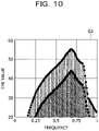
- FIGs. 10 and 11 are diagrams for describing a problem of the related art.
- FIG. 10 is described.
- a horizontal axis of a graph G1 illustrated in FIG. 10 is an axis corresponding to frequencies, and a vertical axis is an axis corresponding to EMI values.
- EMI values are output in increments of 9.7 MHz from 30 MHz to 1 GHz.
- the EMI values are output in increments of 9.7 MHz, when the related art is applied as it is, a 101-dimensional regression is performed, and the load of the machine learning processing increases.
- FIG. 11 is described.
- a horizontal axis of a graph G2 illustrated in FIG. 11 is an axis corresponding to frequencies, and a vertical axis is an axis corresponding to EMI values.
- a line l1 indicates EMI values for each frequency used when training the machine learning model.
- a line 12 indicates EMI values for each frequency output by the trained machine learning model.
- a peak of an EMI value is often steep, and in a case where a 101-dimensional average error or the like is used as a loss function, training is performed so as to reduce an error of another portion rather than increase an error in an attempt to hit the peak, so that the peak is shifted. Also in the graph G2, a peak of the line l1 and a peak of the line 12 are shifted from each other.
- an object of the present disclosure is to provide an EMI calculation program, an EMI calculation method, and an EMI calculation apparatus capable of reducing a load of machine learning processing and generating a machine learning model that accurately predicts an EMI value at each frequency.
- a load of machine learning processing may be reduced, and a machine learning model that accurately predicts an EMI value at each frequency may be generated.
- FIG. 1 is a diagram for describing the processing of the EMI calculation apparatus according to the present embodiment.
- a horizontal axis of a graph G3 illustrated in FIG. 1 is an axis corresponding to frequencies, and a vertical axis is an axis corresponding to EMI values.
- a machine learning model 141 that outputs an EMI value corresponding to the input resonance frequency is trained in advance and used.
- the EMI calculation apparatus holds an EMI information table 142 in which a relationship between a circuit having a known EMI value at each frequency and a frequency characteristic of an impedance of the circuit is defined.
- the frequency characteristic of the impedance is referred to as an "impedance characteristic" as appropriate.
- An EMI value at each frequency is collectively referred to as "EMI information”.
- a circuit of which an EMI value at each frequency and an impedance characteristic are known is referred to as an "analyzed circuit”.
- a circuit that is an estimation target of an EMI value is referred to as an "estimation target circuit”.
- the EMI calculation apparatus 100 After receiving input of an estimation target circuit 40, the EMI calculation apparatus 100 inputs resonance frequencies of the estimation target circuit 40 to the machine learning model 141 to specify EMI values 40a and 40b corresponding to the resonance frequencies of the estimation target circuit 40.
- the EMI calculation apparatus 100 specifies an analyzed circuit having an impedance characteristic similar to an impedance characteristic of the estimation target circuit 40, and acquires EMI information 40c of the specified analyzed circuit.
- the EMI calculation apparatus 100 generates EMI information 40d by correcting a shape of the entire EMI information 40c such that peak values of the EMI information 40c matches the EMI values 40a and 40b corresponding to the resonance frequencies.
- the EMI calculation apparatus 100 outputs the EMI information 40d as the EMI value at each frequency of the estimation target circuit 40.
- the EMI value of the resonance frequency of the estimation target circuit is specified by using the machine learning model 141.
- the EMI calculation apparatus 100 calculates EMI values at remaining frequencies other than the resonance frequency by using the EMI value at each frequency of the analyzed circuit having a characteristic similar to the impedance characteristic of the estimation target circuit. Since the machine learning model 141 is trained by a relationship between the resonance frequency and the EMI value, it is possible to reduce the load expected for machine learning of the machine learning model as compared with a case where the machine learning is executed by using the EMI value at each frequency respectively.
- FIG. 2 is a diagram illustrating an example in which, although EMI values at resonance frequencies are close to each other, EMI values at other frequencies are different from each other.
- a horizontal axis of graphs G4 and G5 illustrated in FIG. 2 is an axis corresponding to frequencies, and a vertical axis is an axis corresponding to EMI values.
- the respective EMI information in the graph G4 and EMI information in the graph G5 different EMI values at different frequencies of the analyzed circuit are used. Comparing the graph G4 with the graph G5, the EMI values at the resonance frequencies of the graph G4 are similar to the EMI values at the resonance frequencies of the graph G5, but the EMI values at the other frequencies are not coincident with each other.
- the EMI value at each frequency of the estimation target circuit may not be calculated with high accuracy by the method of extracting the EMI information in which the EMI values of the resonance frequencies are close to each other, from the EMI information of the analyzed circuit.
- the EMI calculation apparatus 100 performs calculation by correcting the EMI information of the analyzed circuit having a characteristic similar to the impedance characteristic of the estimation target circuit based on the EMI values of the remaining frequencies other than the resonance frequency. Accordingly, it is possible to calculate the EMI values at all frequencies without impairing the accuracy of estimating the EMI value.
- the impedance affects current intensity and the current intensity affects the electromagnetic noise intensity, it is possible to approximate fine fluctuations of the EMI values other than the resonance frequency by using the EMI information of the analyzed circuit close to the impedance characteristic.
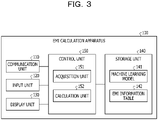
- FIG. 3 is a functional block diagram illustrating the configuration of the EMI calculation apparatus according to the present embodiment.
- the EMI calculation apparatus 100 includes a communication unit 110, an input unit 120, a display unit 130, a storage unit 140, and a control unit 150.
- the communication unit 110 performs data communication with an external apparatus (not illustrated) via a network.
- the communication unit 110 receives information on the estimation target circuit or the like from the external apparatus.
- the input unit 120 receives various kinds of data from a user or the like and inputs the various kinds of data to the EMI calculation apparatus 100.
- the display unit 130 displays information output from the control unit 150.
- the display unit 130 displays EMI information or the like of the estimation target circuit output from the control unit 150.
- the storage unit 140 stores data, a program to be executed by the control unit 150, and the like.
- the storage unit 140 stores the machine learning model 141 and the EMI information table 142.
- the machine learning model 141 has been trained in advance by training data.
- the machine learning model 141 is an example of a neural network.
- the machine learning model 141 is trained based on a back propagation method or the like.
- the training data used in a case of training the machine learning model 141 associates an input "resonance frequency of a circuit” with an output (correct answer data) "EMI value corresponding to the resonance frequency of the circuit".
- an EMI value corresponding to the resonance frequency is output.
- the EMI information table 142 holds impedance characteristics of the analyzed circuits and EMI information in association with each other.
- FIG. 4 is a diagram illustrating an example of a data structure of the EMI information table. As illustrated in FIG. 4 , in the EMI information table 142, circuit identification information, the impedance characteristic, and the EMI information are associated with each other.
- the circuit identification information is information for uniquely identifying the analyzed circuit.
- the impedance characteristic indicates a frequency characteristic of the impedance of the analyzed circuit.
- FIG. 5 is a diagram illustrating an example of the impedance characteristic.
- a horizontal axis of a graph G6 in FIG. 5 is an axis corresponding to frequencies, and a vertical axis is an axis corresponding to absolute values of impedance Zin.
- an impedance value is associated with each frequency.
- the EMI information indicates an EMI value at each frequency of the analyzed circuit.
- FIG. 6 is a diagram illustrating an example of the EMI information.
- a horizontal axis of a graph G7 in FIG. 6 is an axis corresponding to frequencies, and a vertical axis is an axis corresponding to EMI values.
- EMI values corresponding to frequencies are associated for each frequency.
- the control unit 150 includes an acquisition unit 151 and a calculation unit 152.
- the acquisition unit 151 acquires information on the estimation target circuit via the communication unit 110 or the input unit 120.
- the acquisition unit 151 generates equivalent circuit information equivalent to the estimation target circuit based on the information on the estimation target circuit.
- the equivalent circuit information is information obtained by simplifying elements of the estimation target circuit to minimum elements representing the characteristic of the estimation target circuit.
- the acquisition unit 151 inputs the equivalent circuit information to a circuit simulator and acquires a resonance frequency and an impedance characteristic of the estimation target circuit (equivalent circuit information).
- the acquisition unit 151 uses simulation program with integrated circuit emphasis (SPICE) or the like as the circuit simulator.
- SPICE simulation program with integrated circuit emphasis
- the acquisition unit 151 inputs the resonance frequency of the estimation target circuit to the trained machine learning model 141 to acquire an EMI value corresponding to the resonance frequency of the estimation target circuit.
- the acquisition unit 151 outputs the EMI value at the resonance frequency of the estimation target circuit acquired by the above-described processing and the impedance characteristic of the estimation target circuit to the calculation unit 152.
- the calculation unit 152 specifies an impedance characteristic most similar to the impedance characteristic of the estimation target circuit.
- the analyzed circuit having the impedance characteristic most similar to the impedance characteristic of the estimation target circuit is referred to as a "similar circuit”.
- the calculation unit 152 calculates each of absolute values of differences between the impedances at the respective frequencies in the impedance characteristic to be compared, and determines that the compared impedance characteristic is more similar, as the total value of the absolute values is smaller.
- the calculation unit 152 selects EMI information of the similar circuit and acquires the selected EMI information.
- the calculation unit 152 calculates EMI values at other frequencies different from the resonance frequency of the estimation target circuit.
- EMI values of the resonance frequencies of the estimation target circuit are referred to as the EMI values 40a and 40b, and the EMI information of the similar circuit is referred to as EMI information 40c.
- the calculation unit 152 generates EMI information 40d by correcting a shape of the entire EMI information 40c such that peak values of the EMI information 40c match the EMI values 40a and 40b corresponding to the resonance frequencies.
- the EMI calculation apparatus 100 calculates the EMI information 40d as the EMI value at each frequency of the estimation target circuit.
- the calculation unit 152 deforms the peak values of the EMI information 40c in a frequency direction and a direction of the EMI values so that the peak values match the EMI values 40a and 40b.
- the calculation unit 152 may output and display the EMI information 40c of the estimation target circuit on the display unit 130 or may output the EMI information 40c of the estimation target circuit to an external apparatus via the communication unit 110.
- FIG. 7 is a flowchart illustrating the processing procedure of the EMI calculation apparatus according to the present embodiment.
- the acquisition unit 151 of the EMI calculation apparatus 100 receives input of information on the estimation target circuit (step S101).
- the acquisition unit 151 generates equivalent circuit information of the estimation target circuit (step S102).
- the acquisition unit 151 executes the circuit simulator and acquires a resonance frequency and an impedance characteristic of the estimation target circuit (equivalent circuit information) (step S103).
- the acquisition unit 151 inputs the resonance frequency to the machine learning model 141 and acquires an EMI value corresponding to the resonance frequency (step S104).
- the EMI calculation apparatus 100 specifies a similar circuit (step S105).
- the calculation unit 152 acquires EMI information corresponding to the similar circuit (step S106). Based on the EMI value at the resonance frequency of the estimation target circuit and the acquired EMI information, the calculation unit 152 calculates EMI information of the estimation target circuit (step S107). The calculation unit 152 outputs the EMI information of the estimation target circuit (step S108).
- the EMI calculation apparatus 100 specifies the EMI value at the resonance frequency of the estimation target circuit by using the machine learning model 141.
- the EMI calculation apparatus 100 calculates the EMI values at the remaining frequencies other than the resonance frequency by using the EMI information of the similar circuit having a characteristic similar to the impedance characteristic of the estimation target circuit. Since the machine learning model 141 is trained by a relationship between the resonance frequency and the EMI value, it is possible to reduce the load expected for the machine learning of the machine learning model as compared with a case where the machine learning is executed by using the EMI values of all the frequencies respectively.
- the EMI calculation apparatus 100 corrects the shape of the entire EMI information such that the peak value of the EMI information of the similar circuit matches the EMI value corresponding to the resonance frequency of the analyzed circuit. Accordingly, it is possible to calculate the EMI values at all frequencies without impairing the accuracy of estimating the EMI value.
- the EMI calculation apparatus 100 generates equivalent circuit information from information on the estimation target circuit, acquires a resonance frequency by inputting the equivalent circuit information to the circuit simulator, and specifies an EMI value by inputting the acquired resonance frequency to the machine learning model 141. Accordingly, it is possible to efficiently acquire the EMI value corresponding to the resonance frequency of the estimation target circuit.
- the processing of the EMI calculation apparatus 100 described above is an example, and the EMI calculation apparatus 100 may execute other processing.
- the EMI calculation apparatus 100 trains the machine learning model 141 by using the training data, and obtains the EMI value corresponding to the resonance frequency by using the trained machine learning model 141.
- the EMI calculation apparatus 100 may perform training by using training data in which the input "resonance frequency of circuit” and "image of current distribution of circuit” are associated with the output "EMI value corresponding to resonance frequency of circuit".
- the acquisition unit 151 acquires images of the resonance frequency and the current distribution of the estimation target circuit (equivalent circuit information) by using the circuit simulator, inputs the acquired images of the resonance frequency and the current distribution to the machine learning model 141, and calculates the EMI value corresponding to the resonance frequency.
- FIG. 8 is a diagram illustrating an example of the hardware configuration of the computer that implements the same functions as those of the EMI calculation apparatus.
- a computer 200 includes a central processing unit (CPU) 201 that executes various kinds of arithmetic operation processing, an input device 202 that receives input of data from a user, and a display 203.
- the computer 200 includes a communication device 204 that receives data from an external apparatus, and an interface device 205 that is coupled to various devices.
- the computer 200 includes a random-access memory (RAM) 206 that temporarily stores various kinds of information, and a hard disk device 207. Each of the devices 201 to 207 is coupled to a bus 208.
- RAM random-access memory
- the hard disk device 207 includes an acquisition program 207a and a calculation program 207b.
- the CPU 201 reads the acquisition program 207a and the calculation program 207b and loads the programs into the RAM 206.
- the acquisition program 207a functions as an acquisition process 206a.
- the calculation program 207b functions as a calculation process 206b.
- Processing of the acquisition process 206a corresponds to the processing of the acquisition unit 151.
- Processing of the calculation process 206b corresponds to the processing of the calculation unit 152.
- Each of the programs 207a and 207b may not be stored in the hard disk device 207 from the beginning.
- each of the programs are stored in a "portable physical medium" such as a flexible disk (FD), a compact disc read-only memory (CD-ROM), a Digital Versatile Disc (DVD) disc, a magneto-optical disk, and an IC card to be inserted into the computer 200.
- the computer 200 may read and execute each of the programs 207a and 207b.
Landscapes
- Physics & Mathematics (AREA)
- Engineering & Computer Science (AREA)
- General Physics & Mathematics (AREA)
- Computer Hardware Design (AREA)
- Theoretical Computer Science (AREA)
- General Engineering & Computer Science (AREA)
- Electromagnetism (AREA)
- Evolutionary Computation (AREA)
- Geometry (AREA)
- Microelectronics & Electronic Packaging (AREA)
- Artificial Intelligence (AREA)
- Computer Vision & Pattern Recognition (AREA)
- Medical Informatics (AREA)
- Software Systems (AREA)
- Shielding Devices Or Components To Electric Or Magnetic Fields (AREA)
- Management, Administration, Business Operations System, And Electronic Commerce (AREA)
Abstract
Description
- The embodiment discussed herein is related to an EMI calculation technique for calculating electromagnetic radiation in an electronic circuit board.
- An electromagnetic wave is radiated by causing a current to flow through an electronic circuit board (hereafter, referred to as a circuit). A situation in which such electromagnetic wave adversely affects an electronic device or the like as noise is referred to as an electro magnetic interference (EMI). Hereinafter, an intensity of the electromagnetic wave radiated when a current flows through a circuit is referred to as an "EMI value" as appropriate.
- A regulation value is provided for each frequency, and in a case where a circuit is designed, it is desired to design such that an EMI value for each frequency is within the regulation value. For this reason, the EMI value is predicted from circuit information by simulation or deep learning technique.
- Although it is possible to predict an EMI value with high accuracy when the EMI value is predicted by using a simulation, in some cases, a deep learning technique is used instead of the simulation due to high cost. Hereinafter,
Related Art 1 will be described as an example of the related art for predicting an EMI value. -
Related Art 1 will be described.FIG. 9 is a diagram for describingRelated Art 1. InRelated Art 1, a simulation is executed by using some pieces ofcircuit information 10 to calculate an EMI value, and the calculated EMI value is used ascorrect answer data 11. InRelated Art 1, a set of thecircuit information 10 and thecorrect answer data 11 is set as training data, and training of amachine learning model 12 is executed. Themachine learning model 12 corresponds to artificial intelligence (AI) or the like. InRelated Art 1, the EMI value corresponding tocircuit information 13 is calculated by inputtingpractical circuit information 13 to themachine learning model 12. -
Japanese Laid-open Patent Publication Nos. 2002-90403 2020-60877 - However, in the related art described above, in a case where a machine learning model for predicting an EMI value at each frequency is to be generated, there is a problem that a load of machine learning processing increases.
-
FIGs. 10 and11 are diagrams for describing a problem of the related art.FIG. 10 is described. A horizontal axis of a graph G1 illustrated inFIG. 10 is an axis corresponding to frequencies, and a vertical axis is an axis corresponding to EMI values. In the graph G1, EMI values are output in increments of 9.7 MHz from 30 MHz to 1 GHz. As described above, in a case where the EMI values are output in increments of 9.7 MHz, when the related art is applied as it is, a 101-dimensional regression is performed, and the load of the machine learning processing increases. -
FIG. 11 is described. A horizontal axis of a graph G2 illustrated inFIG. 11 is an axis corresponding to frequencies, and a vertical axis is an axis corresponding to EMI values. A line l1 indicates EMI values for each frequency used when training the machine learning model. Aline 12 indicates EMI values for each frequency output by the trained machine learning model. A peak of an EMI value is often steep, and in a case where a 101-dimensional average error or the like is used as a loss function, training is performed so as to reduce an error of another portion rather than increase an error in an attempt to hit the peak, so that the peak is shifted. Also in the graph G2, a peak of the line l1 and a peak of theline 12 are shifted from each other. - According to one aspect, an object of the present disclosure is to provide an EMI calculation program, an EMI calculation method, and an EMI calculation apparatus capable of reducing a load of machine learning processing and generating a machine learning model that accurately predicts an EMI value at each frequency.
- A load of machine learning processing may be reduced, and a machine learning model that accurately predicts an EMI value at each frequency may be generated.
-
- FIG. 1 is a diagram for describing processing of an EMI calculation apparatus according to a present embodiment;
- FIG. 2 is a diagram illustrating an example in which, although EMI values at resonance frequencies are close to each other, EMI values at other frequencies are different from each other;
- FIG. 3 is a functional block diagram illustrating a configuration of an EMI calculation apparatus according to the present embodiment;
- FIG. 4 is a diagram illustrating an example of a data structure of an EMI information table;
- FIG. 5 is a diagram illustrating an example of an impedance characteristic;
- FIG. 6 is a diagram illustrating an example of EMI information;
- FIG. 7 is a flowchart illustrating a processing procedure of an EMI calculation apparatus according to the present embodiment;
- FIG. 8 is a diagram illustrating an example of a hardware configuration of a computer that implements the same functions as those of an EMI calculation apparatus;
- FIG. 9 is a diagram for describing
Japanese Laid-open Patent Publication No. 2002-90403 - FIG. 10 is a diagram (1) for describing a problem of the related art; and
- FIG. 11 is a diagram (2) for describing a problem of the related art.
- Hereinafter, an embodiment of an EMI calculation program, an EMI calculation method, and an EMI calculation apparatus disclosed in the present application will be described in detail with reference to the drawings. This disclosure is not limited by the embodiment.
- An example of processing of an EMI calculation apparatus according to the present embodiment will be described.
FIG. 1 is a diagram for describing the processing of the EMI calculation apparatus according to the present embodiment. A horizontal axis of a graph G3 illustrated inFIG. 1 is an axis corresponding to frequencies, and a vertical axis is an axis corresponding to EMI values. - In the
EMI calculation apparatus 100, when a resonance frequency is input, amachine learning model 141 that outputs an EMI value corresponding to the input resonance frequency is trained in advance and used. The EMI calculation apparatus holds an EMI information table 142 in which a relationship between a circuit having a known EMI value at each frequency and a frequency characteristic of an impedance of the circuit is defined. - Hereinafter, the frequency characteristic of the impedance is referred to as an "impedance characteristic" as appropriate. An EMI value at each frequency is collectively referred to as "EMI information". A circuit of which an EMI value at each frequency and an impedance characteristic are known is referred to as an "analyzed circuit". A circuit that is an estimation target of an EMI value is referred to as an "estimation target circuit".
- After receiving input of an
estimation target circuit 40, theEMI calculation apparatus 100 inputs resonance frequencies of theestimation target circuit 40 to themachine learning model 141 to specifyEMI values estimation target circuit 40. - The
EMI calculation apparatus 100 specifies an analyzed circuit having an impedance characteristic similar to an impedance characteristic of theestimation target circuit 40, and acquiresEMI information 40c of the specified analyzed circuit. - The
EMI calculation apparatus 100 generatesEMI information 40d by correcting a shape of theentire EMI information 40c such that peak values of theEMI information 40c matches theEMI values EMI calculation apparatus 100 outputs theEMI information 40d as the EMI value at each frequency of theestimation target circuit 40. - As described above, according to the
EMI calculation apparatus 100 according to the present embodiment, the EMI value of the resonance frequency of the estimation target circuit is specified by using themachine learning model 141. TheEMI calculation apparatus 100 calculates EMI values at remaining frequencies other than the resonance frequency by using the EMI value at each frequency of the analyzed circuit having a characteristic similar to the impedance characteristic of the estimation target circuit. Since themachine learning model 141 is trained by a relationship between the resonance frequency and the EMI value, it is possible to reduce the load expected for machine learning of the machine learning model as compared with a case where the machine learning is executed by using the EMI value at each frequency respectively. - In a case where the EMI values of the remaining frequencies are interpolated based on the EMI value of the resonance frequency, a method of simply extracting EMI information in which the EMI values of the resonance frequencies are close to each other, from the EMI values at each of the frequencies of the analyzed circuit is conceivable. However, even in a case where the EMI values at the resonance frequencies are close to each other, the other frequencies may not coincide with each other.
-
FIG. 2 is a diagram illustrating an example in which, although EMI values at resonance frequencies are close to each other, EMI values at other frequencies are different from each other. A horizontal axis of graphs G4 and G5 illustrated inFIG. 2 is an axis corresponding to frequencies, and a vertical axis is an axis corresponding to EMI values. As for the respective EMI information in the graph G4 and EMI information in the graph G5, different EMI values at different frequencies of the analyzed circuit are used. Comparing the graph G4 with the graph G5, the EMI values at the resonance frequencies of the graph G4 are similar to the EMI values at the resonance frequencies of the graph G5, but the EMI values at the other frequencies are not coincident with each other. - For example, in a case where the EMI values of the remaining frequencies are interpolated based on the EMI value of the resonance frequency, the EMI value at each frequency of the estimation target circuit may not be calculated with high accuracy by the method of extracting the EMI information in which the EMI values of the resonance frequencies are close to each other, from the EMI information of the analyzed circuit.
- On the other hand, as described with reference to
FIG. 1 , theEMI calculation apparatus 100 according to the present embodiment performs calculation by correcting the EMI information of the analyzed circuit having a characteristic similar to the impedance characteristic of the estimation target circuit based on the EMI values of the remaining frequencies other than the resonance frequency. Accordingly, it is possible to calculate the EMI values at all frequencies without impairing the accuracy of estimating the EMI value. - Since the impedance affects current intensity and the current intensity affects the electromagnetic noise intensity, it is possible to approximate fine fluctuations of the EMI values other than the resonance frequency by using the EMI information of the analyzed circuit close to the impedance characteristic.
- Next, an example of a configuration of the
EMI calculation apparatus 100 according to the present embodiment will be described.FIG. 3 is a functional block diagram illustrating the configuration of the EMI calculation apparatus according to the present embodiment. As illustrated inFIG. 3 , theEMI calculation apparatus 100 includes acommunication unit 110, aninput unit 120, adisplay unit 130, astorage unit 140, and acontrol unit 150. - The
communication unit 110 performs data communication with an external apparatus (not illustrated) via a network. For example, thecommunication unit 110 receives information on the estimation target circuit or the like from the external apparatus. - The
input unit 120 receives various kinds of data from a user or the like and inputs the various kinds of data to theEMI calculation apparatus 100. - The
display unit 130 displays information output from thecontrol unit 150. For example, thedisplay unit 130 displays EMI information or the like of the estimation target circuit output from thecontrol unit 150. - The
storage unit 140 stores data, a program to be executed by thecontrol unit 150, and the like. Thestorage unit 140 stores themachine learning model 141 and the EMI information table 142. - It is assumed that the
machine learning model 141 has been trained in advance by training data. Themachine learning model 141 is an example of a neural network. For example, themachine learning model 141 is trained based on a back propagation method or the like. - The training data used in a case of training the
machine learning model 141 associates an input "resonance frequency of a circuit" with an output (correct answer data) "EMI value corresponding to the resonance frequency of the circuit". By inputting the resonance frequency to the trainedmachine learning model 141, an EMI value corresponding to the resonance frequency is output. - For a plurality of analyzed circuits, the EMI information table 142 holds impedance characteristics of the analyzed circuits and EMI information in association with each other.
FIG. 4 is a diagram illustrating an example of a data structure of the EMI information table. As illustrated inFIG. 4 , in the EMI information table 142, circuit identification information, the impedance characteristic, and the EMI information are associated with each other. The circuit identification information is information for uniquely identifying the analyzed circuit. - The impedance characteristic indicates a frequency characteristic of the impedance of the analyzed circuit.
FIG. 5 is a diagram illustrating an example of the impedance characteristic. A horizontal axis of a graph G6 inFIG. 5 is an axis corresponding to frequencies, and a vertical axis is an axis corresponding to absolute values of impedance Zin. As illustrated inFIG. 5 , in the impedance characteristic, an impedance value is associated with each frequency. - The EMI information indicates an EMI value at each frequency of the analyzed circuit.
FIG. 6 is a diagram illustrating an example of the EMI information. A horizontal axis of a graph G7 inFIG. 6 is an axis corresponding to frequencies, and a vertical axis is an axis corresponding to EMI values. As illustrated inFIG. 6 , in the EMI information, EMI values corresponding to frequencies are associated for each frequency. - The description returns to
FIG. 3 . Thecontrol unit 150 includes anacquisition unit 151 and a calculation unit 152. - The
acquisition unit 151 acquires information on the estimation target circuit via thecommunication unit 110 or theinput unit 120. Theacquisition unit 151 generates equivalent circuit information equivalent to the estimation target circuit based on the information on the estimation target circuit. The equivalent circuit information is information obtained by simplifying elements of the estimation target circuit to minimum elements representing the characteristic of the estimation target circuit. - The
acquisition unit 151 inputs the equivalent circuit information to a circuit simulator and acquires a resonance frequency and an impedance characteristic of the estimation target circuit (equivalent circuit information). For example, theacquisition unit 151 uses simulation program with integrated circuit emphasis (SPICE) or the like as the circuit simulator. - Subsequently, the
acquisition unit 151 inputs the resonance frequency of the estimation target circuit to the trainedmachine learning model 141 to acquire an EMI value corresponding to the resonance frequency of the estimation target circuit. - The
acquisition unit 151 outputs the EMI value at the resonance frequency of the estimation target circuit acquired by the above-described processing and the impedance characteristic of the estimation target circuit to the calculation unit 152. - By comparing the impedance characteristic of the estimation target circuit with the impedance characteristic of each analyzed circuit registered in the EMI information table 142, the calculation unit 152 specifies an impedance characteristic most similar to the impedance characteristic of the estimation target circuit. Hereinafter, the analyzed circuit having the impedance characteristic most similar to the impedance characteristic of the estimation target circuit is referred to as a "similar circuit".
- For example, the calculation unit 152 calculates each of absolute values of differences between the impedances at the respective frequencies in the impedance characteristic to be compared, and determines that the compared impedance characteristic is more similar, as the total value of the absolute values is smaller.
- From the plurality of pieces of EMI information included in the EMI information table 142, the calculation unit 152 selects EMI information of the similar circuit and acquires the selected EMI information.
- Subsequently, based on the EMI value at the resonance frequency of the estimation target circuit and the EMI information of the similar circuit, the calculation unit 152 calculates EMI values at other frequencies different from the resonance frequency of the estimation target circuit.
- Processing of the calculation unit 152 will be described with reference to the above-described
FIG. 1 . EMI values of the resonance frequencies of the estimation target circuit are referred to as the EMI values 40a and 40b, and the EMI information of the similar circuit is referred to asEMI information 40c. The calculation unit 152 generatesEMI information 40d by correcting a shape of theentire EMI information 40c such that peak values of theEMI information 40c match the EMI values 40a and 40b corresponding to the resonance frequencies. TheEMI calculation apparatus 100 calculates theEMI information 40d as the EMI value at each frequency of the estimation target circuit. - In a case of correcting the shape of the
entire EMI information 40c, the calculation unit 152 deforms the peak values of theEMI information 40c in a frequency direction and a direction of the EMI values so that the peak values match the EMI values 40a and 40b. The calculation unit 152 may output and display theEMI information 40c of the estimation target circuit on thedisplay unit 130 or may output theEMI information 40c of the estimation target circuit to an external apparatus via thecommunication unit 110. - Next, an example of a processing procedure of the
EMI calculation apparatus 100 according to the present embodiment will be described.FIG. 7 is a flowchart illustrating the processing procedure of the EMI calculation apparatus according to the present embodiment. As illustrated inFIG. 7 , theacquisition unit 151 of theEMI calculation apparatus 100 receives input of information on the estimation target circuit (step S101). - The
acquisition unit 151 generates equivalent circuit information of the estimation target circuit (step S102). Theacquisition unit 151 executes the circuit simulator and acquires a resonance frequency and an impedance characteristic of the estimation target circuit (equivalent circuit information) (step S103). - The
acquisition unit 151 inputs the resonance frequency to themachine learning model 141 and acquires an EMI value corresponding to the resonance frequency (step S104). By comparing the impedance characteristic of the estimation target circuit with the impedance characteristic in the EMI information table 142, theEMI calculation apparatus 100 specifies a similar circuit (step S105). - From the EMI information table 142, the calculation unit 152 acquires EMI information corresponding to the similar circuit (step S106). Based on the EMI value at the resonance frequency of the estimation target circuit and the acquired EMI information, the calculation unit 152 calculates EMI information of the estimation target circuit (step S107). The calculation unit 152 outputs the EMI information of the estimation target circuit (step S108).
- Next, effects of the
EMI calculation apparatus 100 according to the present embodiment will be described. TheEMI calculation apparatus 100 specifies the EMI value at the resonance frequency of the estimation target circuit by using themachine learning model 141. TheEMI calculation apparatus 100 calculates the EMI values at the remaining frequencies other than the resonance frequency by using the EMI information of the similar circuit having a characteristic similar to the impedance characteristic of the estimation target circuit. Since themachine learning model 141 is trained by a relationship between the resonance frequency and the EMI value, it is possible to reduce the load expected for the machine learning of the machine learning model as compared with a case where the machine learning is executed by using the EMI values of all the frequencies respectively. - The
EMI calculation apparatus 100 corrects the shape of the entire EMI information such that the peak value of the EMI information of the similar circuit matches the EMI value corresponding to the resonance frequency of the analyzed circuit. Accordingly, it is possible to calculate the EMI values at all frequencies without impairing the accuracy of estimating the EMI value. - The
EMI calculation apparatus 100 generates equivalent circuit information from information on the estimation target circuit, acquires a resonance frequency by inputting the equivalent circuit information to the circuit simulator, and specifies an EMI value by inputting the acquired resonance frequency to themachine learning model 141. Accordingly, it is possible to efficiently acquire the EMI value corresponding to the resonance frequency of the estimation target circuit. - By the way, the processing of the
EMI calculation apparatus 100 described above is an example, and theEMI calculation apparatus 100 may execute other processing. For example, theEMI calculation apparatus 100 trains themachine learning model 141 by using the training data, and obtains the EMI value corresponding to the resonance frequency by using the trainedmachine learning model 141. - In a case where the
machine learning model 141 is trained, theEMI calculation apparatus 100 may perform training by using training data in which the input "resonance frequency of circuit" and "image of current distribution of circuit" are associated with the output "EMI value corresponding to resonance frequency of circuit". In this case, theacquisition unit 151 acquires images of the resonance frequency and the current distribution of the estimation target circuit (equivalent circuit information) by using the circuit simulator, inputs the acquired images of the resonance frequency and the current distribution to themachine learning model 141, and calculates the EMI value corresponding to the resonance frequency. - Next, an example of a hardware configuration of a computer that implements functions similar to those of the
EMI calculation apparatus 100 described in the above embodiment will be described.FIG. 8 is a diagram illustrating an example of the hardware configuration of the computer that implements the same functions as those of the EMI calculation apparatus. - As illustrated in
FIG. 8 , acomputer 200 includes a central processing unit (CPU) 201 that executes various kinds of arithmetic operation processing, an input device 202 that receives input of data from a user, and adisplay 203. Thecomputer 200 includes a communication device 204 that receives data from an external apparatus, and aninterface device 205 that is coupled to various devices. Thecomputer 200 includes a random-access memory (RAM) 206 that temporarily stores various kinds of information, and ahard disk device 207. Each of thedevices 201 to 207 is coupled to abus 208. - The
hard disk device 207 includes anacquisition program 207a and acalculation program 207b. TheCPU 201 reads theacquisition program 207a and thecalculation program 207b and loads the programs into theRAM 206. - The
acquisition program 207a functions as anacquisition process 206a. Thecalculation program 207b functions as acalculation process 206b. - Processing of the
acquisition process 206a corresponds to the processing of theacquisition unit 151. Processing of thecalculation process 206b corresponds to the processing of the calculation unit 152. - Each of the
programs hard disk device 207 from the beginning. For example, each of the programs are stored in a "portable physical medium" such as a flexible disk (FD), a compact disc read-only memory (CD-ROM), a Digital Versatile Disc (DVD) disc, a magneto-optical disk, and an IC card to be inserted into thecomputer 200. Thecomputer 200 may read and execute each of theprograms
Claims (12)
- An EMI calculation program that causes at least one computer to execute a process, the process comprising:inputting circuit information of a first circuit to a machine learning model;acquiring an EMI value at a certain frequency of the first circuit;selecting, based on an impedance characteristic of the first circuit and the EMI value at the certain frequency, first EMI information from a plurality of pieces of EMI information in each of which an impedance characteristic of each of a plurality of circuits is associated with EMI values at a plurality of frequencies of each of the plurality of circuits; andacquiring an EMI value at another frequency different from the certain frequency of the first circuit based on the EMI value at the certain frequency and the first EMI information.
- The EMI calculation program according to claim 1, wherein
the selecting includes selecting EMI information of a circuit corresponding to an impedance characteristic similar to the impedance characteristic of the first circuit among the plurality of pieces of EMI information as the first EMI information. - The EMI calculation program according to claim 1 or 2, wherein
the acquiring the EMI value at another frequency includes:specifying a maximum EMI value among the EMI values at the plurality of frequencies included in the first EMI information; andacquiring the EMI value at another frequency by correcting a relationship between the plurality of frequencies of the first EMI information and the EMI value so that the maximum EMI value being close to the EMI value at the certain frequency. - The EMI calculation program according to any one of claims 1 to 3, wherein
the acquiring the EMI value at the certain frequency includes:inputting a resonance frequency of the first circuit to the machine learning model as the circuit information; andacquiring an EMI value at the resonance frequency. - An EMI calculation method for a computer to execute a process comprising:inputting circuit information of a first circuit to a machine learning model;acquiring an EMI value at a certain frequency of the first circuit;selecting, based on an impedance characteristic of the first circuit and the EMI value at the certain frequency, first EMI information from a plurality of pieces of EMI information in each of which an impedance characteristic of each of a plurality of circuits is associated with EMI values at a plurality of frequencies of each of the plurality of circuits; andacquiring an EMI value at another frequency different from the certain frequency of the first circuit based on the EMI value at the certain frequency and the first EMI information.
- The EMI calculation method according to claim 5, wherein
the selecting includes selecting EMI information of a circuit corresponding to an impedance characteristic similar to the impedance characteristic of the first circuit among the plurality of pieces of EMI information as the first EMI information. - The EMI calculation method according to claim 5 or 6, wherein
the acquiring the EMI value at another frequency includes:specifying a maximum EMI value among the EMI values at the plurality of frequencies included in the first EMI information; andacquiring the EMI value at another frequency by correcting a relationship between the plurality of frequencies of the first EMI information and the EMI value so that the maximum EMI value being close to the EMI value at the certain frequency. - The EMI calculation method according to any one of claims 5 to 7, wherein
the acquiring the EMI value at the certain frequency includes:inputting a resonance frequency of the first circuit to the machine learning model as the circuit information; andacquiring an EMI value at the resonance frequency. - An EMI calculation apparatus comprising:
a control unit configured to:input circuit information of a first circuit to a machine learning model,acquire an EMI value at a certain frequency of the first circuit, select, based on an impedance characteristic of the first circuit and the EMI value at the certain frequency, first EMI information from a plurality of pieces of EMI information in each of which an impedance characteristic of each of a plurality of circuits is associated with EMI values at a plurality of frequencies of each of the plurality of circuits, andacquire an EMI value at another frequency different from the certain frequency of the first circuit based on the EMI value at the certain frequency and the first EMI information. - The EMI calculation apparatus according to claim 9, wherein the control unit is further configured to
select EMI information of a circuit corresponding to an impedance characteristic similar to the impedance characteristic of the first circuit among the plurality of pieces of EMI information as the first EMI information. - The EMI calculation apparatus according to claim 9 or 10, wherein the control unit is further configured to:specify a maximum EMI value among the EMI values at the plurality of frequencies included in the first EMI information, andacquire the EMI value at another frequency by correcting a relationship between the plurality of frequencies of the first EMI information and the EMI value so that the maximum EMI value being close to the EMI value at the certain frequency.
- The EMI calculation apparatus according to any one of claims 9 to 11, wherein the control unit is further configured to:input a resonance frequency of the first circuit to the machine learning model as the circuit information, andacquire an EMI value at the resonance frequency.
Applications Claiming Priority (1)
| Application Number | Priority Date | Filing Date | Title |
|---|---|---|---|
| JP2021072550A JP7658152B2 (en) | 2021-04-22 | 2021-04-22 | EMI calculation program, EMI calculation method, and EMI calculation device |
Publications (1)
| Publication Number | Publication Date |
|---|---|
| EP4080398A1 true EP4080398A1 (en) | 2022-10-26 |
Family
ID=80447699
Family Applications (1)
| Application Number | Title | Priority Date | Filing Date |
|---|---|---|---|
| EP22156094.9A Pending EP4080398A1 (en) | 2021-04-22 | 2022-02-10 | Emi calculation program, emi calculation method, and emi calculation apparatus |
Country Status (3)
| Country | Link |
|---|---|
| US (1) | US11719733B2 (en) |
| EP (1) | EP4080398A1 (en) |
| JP (1) | JP7658152B2 (en) |
Families Citing this family (2)
| Publication number | Priority date | Publication date | Assignee | Title |
|---|---|---|---|---|
| WO2025134410A1 (en) * | 2023-12-19 | 2025-06-26 | 株式会社デンソー | Analysis device, analysis program, method, semiconductor device, and semiconductor wafer |
| CN117434372B (en) * | 2023-12-21 | 2024-03-08 | 深圳信测标准技术服务股份有限公司 | Electromagnetic compatibility immunity test method and system for electronic product |
Citations (2)
| Publication number | Priority date | Publication date | Assignee | Title |
|---|---|---|---|---|
| JP2002090403A (en) | 2000-07-06 | 2002-03-27 | Fujitsu Ltd | Electromagnetic wave analysis processing device, computer-readable storage medium, and electromagnetic wave analysis processing program |
| US20200110850A1 (en) * | 2018-10-05 | 2020-04-09 | Fujitsu Limited | Non-transitory computer-readable storage medium storing estimation program, estimation device, and estimation method |
Family Cites Families (7)
| Publication number | Priority date | Publication date | Assignee | Title |
|---|---|---|---|---|
| JPH08122377A (en) * | 1994-10-21 | 1996-05-17 | Fujitsu Ltd | Electromagnetic field strength calculator |
| US6711511B2 (en) | 2000-07-06 | 2004-03-23 | Fujitsu Limited | Electromagnetic wave analyzing apparatus and computer readable storage medium |
| US7253642B2 (en) * | 2004-12-23 | 2007-08-07 | Power Survey Company | Method for sensing an electric field |
| US9772363B2 (en) * | 2014-02-26 | 2017-09-26 | Nokomis, Inc. | Automated analysis of RF effects on electronic devices through the use of device unintended emissions |
| US20180321293A1 (en) * | 2017-05-01 | 2018-11-08 | Elite Rf Llc | Multi-Purpose RF Test System |
| WO2020095362A1 (en) * | 2018-11-06 | 2020-05-14 | 三菱電機株式会社 | Design assistance device, design assistance method, and machine learning device |
| CN114520504A (en) * | 2020-11-20 | 2022-05-20 | 美商新思科技有限公司 | Automated method for checking electrostatic discharge effects on a sacrificial device |
-
2021
- 2021-04-22 JP JP2021072550A patent/JP7658152B2/en active Active
-
2022
- 2022-02-10 EP EP22156094.9A patent/EP4080398A1/en active Pending
- 2022-02-22 US US17/676,828 patent/US11719733B2/en active Active
Patent Citations (2)
| Publication number | Priority date | Publication date | Assignee | Title |
|---|---|---|---|---|
| JP2002090403A (en) | 2000-07-06 | 2002-03-27 | Fujitsu Ltd | Electromagnetic wave analysis processing device, computer-readable storage medium, and electromagnetic wave analysis processing program |
| US20200110850A1 (en) * | 2018-10-05 | 2020-04-09 | Fujitsu Limited | Non-transitory computer-readable storage medium storing estimation program, estimation device, and estimation method |
Non-Patent Citations (2)
| Title |
|---|
| BOUBIN MATTHEW ET AL: "EMI Diagnostics of Three Phase Inverters Using Machine Learning Algorithms", 2018 IEEE ENERGY CONVERSION CONGRESS AND EXPOSITION (ECCE), IEEE, 23 September 2018 (2018-09-23), pages 4062 - 4069, XP033463472, [retrieved on 20181203], DOI: 10.1109/ECCE.2018.8557401 * |
| MOSTEFAOUI-KASRI KAHINA ET AL: "Calculation of conducted EMI generated by single-ended primary inductance converter", INTERNATIONAL REVIEW OF ELECTRICAL ENGINEERING, 1 May 2012 (2012-05-01), pages 4469 - 4479, XP055945648, Retrieved from the Internet <URL:https://hal.archives-ouvertes.fr/hal-00926436/document> [retrieved on 20220725] * |
Also Published As
| Publication number | Publication date |
|---|---|
| JP7658152B2 (en) | 2025-04-08 |
| JP2022167044A (en) | 2022-11-04 |
| US11719733B2 (en) | 2023-08-08 |
| US20220341979A1 (en) | 2022-10-27 |
Similar Documents
| Publication | Publication Date | Title |
|---|---|---|
| EP4080398A1 (en) | Emi calculation program, emi calculation method, and emi calculation apparatus | |
| CN109961780B (en) | A man-machine interaction method a device(s) Server and storage medium | |
| EP2352121A1 (en) | Image processing apparatus and method | |
| CN111831114B (en) | Driving voltage generation method and device, storage medium and electronic equipment | |
| MXPA05008740A (en) | Method and apparatus for multi-sensory speech enhancement. | |
| JP6599057B1 (en) | Design support device, design support method, and machine learning device | |
| US9684970B2 (en) | Fast adaptive estimation of motion blur for coherent rendering | |
| CN109903375B (en) | Model generation method, device, storage medium and electronic equipment | |
| US11983880B2 (en) | Mini-batch learning apparatus, operation program of mini-batch learning apparatus, and operation method of mini-batch learning apparatus | |
| US6578181B2 (en) | Device and method for analyzing a circuit, and a computer product | |
| WO2024120445A1 (en) | Model input information determination method, apparatus, device and system, and storage medium | |
| CN113177891B (en) | Image processing method, device, electronic equipment and storage medium | |
| CN119002882A (en) | Method, computer device and computer readable storage medium for generating low-code interface based on artificial intelligence large model | |
| CN113127019B (en) | Verification method and related equipment | |
| EP3910523B1 (en) | Machine learning program, method and device for estimating the electromagnetic wave radiation situation of an electronic circuit | |
| EP3896648A1 (en) | Mini-batch learning device, and operation program and operation method therefor | |
| CN109034085B (en) | Method and apparatus for generating information | |
| US20230237381A1 (en) | Non-transitory computer-readable recording medium storing training data generation program, training data generation method, and training data generation device | |
| US6654712B1 (en) | Method to reduce skew in clock signal distribution using balanced wire widths | |
| JP5682080B2 (en) | Optimal system accuracy definition algorithm guided by architecture for custom integrated circuits | |
| TW200905509A (en) | System and method for modeling semiconductor devices using pre-processing | |
| Germain et al. | Event-based design strategy for circuit electromagnetic compatibility | |
| US20230367937A1 (en) | System and Method for Generating Device Model Parameter | |
| CN112462765B (en) | Robot, control method and device thereof, and computer-readable storage medium | |
| US20220147668A1 (en) | Reducing burn-in for monte-carlo simulations via machine learning |
Legal Events
| Date | Code | Title | Description |
|---|---|---|---|
| PUAI | Public reference made under article 153(3) epc to a published international application that has entered the european phase |
Free format text: ORIGINAL CODE: 0009012 |
|
| STAA | Information on the status of an ep patent application or granted ep patent |
Free format text: STATUS: THE APPLICATION HAS BEEN PUBLISHED |
|
| AK | Designated contracting states |
Kind code of ref document: A1 Designated state(s): AL AT BE BG CH CY CZ DE DK EE ES FI FR GB GR HR HU IE IS IT LI LT LU LV MC MK MT NL NO PL PT RO RS SE SI SK SM TR |
|
| STAA | Information on the status of an ep patent application or granted ep patent |
Free format text: STATUS: REQUEST FOR EXAMINATION WAS MADE |
|
| 17P | Request for examination filed |
Effective date: 20230112 |
|
| RBV | Designated contracting states (corrected) |
Designated state(s): AL AT BE BG CH CY CZ DE DK EE ES FI FR GB GR HR HU IE IS IT LI LT LU LV MC MK MT NL NO PL PT RO RS SE SI SK SM TR |
|
| STAA | Information on the status of an ep patent application or granted ep patent |
Free format text: STATUS: EXAMINATION IS IN PROGRESS |
|
| 17Q | First examination report despatched |
Effective date: 20251020 |