EP4080182A1 - System and method for measuring terminal connection or disconnection and pressure by using pressure sensor - Google Patents
System and method for measuring terminal connection or disconnection and pressure by using pressure sensor Download PDFInfo
- Publication number
- EP4080182A1 EP4080182A1 EP21894851.1A EP21894851A EP4080182A1 EP 4080182 A1 EP4080182 A1 EP 4080182A1 EP 21894851 A EP21894851 A EP 21894851A EP 4080182 A1 EP4080182 A1 EP 4080182A1
- Authority
- EP
- European Patent Office
- Prior art keywords
- pressure
- terminal
- bolt
- coupling
- pressure sensor
- Prior art date
- Legal status (The legal status is an assumption and is not a legal conclusion. Google has not performed a legal analysis and makes no representation as to the accuracy of the status listed.)
- Granted
Links
Images


Classifications
-
- H—ELECTRICITY
- H01—ELECTRIC ELEMENTS
- H01R—ELECTRICALLY-CONDUCTIVE CONNECTIONS; STRUCTURAL ASSOCIATIONS OF A PLURALITY OF MUTUALLY-INSULATED ELECTRICAL CONNECTING ELEMENTS; COUPLING DEVICES; CURRENT COLLECTORS
- H01R4/00—Electrically-conductive connections between two or more conductive members in direct contact, i.e. touching one another; Means for effecting or maintaining such contact; Electrically-conductive connections having two or more spaced connecting locations for conductors and using contact members penetrating insulation
- H01R4/28—Clamped connections, spring connections
- H01R4/30—Clamped connections, spring connections utilising a screw or nut clamping member
- H01R4/302—Clamped connections, spring connections utilising a screw or nut clamping member having means for preventing loosening of screw or nut, e.g. vibration-proof connection
-
- G—PHYSICS
- G01—MEASURING; TESTING
- G01L—MEASURING FORCE, STRESS, TORQUE, WORK, MECHANICAL POWER, MECHANICAL EFFICIENCY, OR FLUID PRESSURE
- G01L1/00—Measuring force or stress, in general
- G01L1/04—Measuring force or stress, in general by measuring elastic deformation of gauges, e.g. of springs
- G01L1/044—Measuring force or stress, in general by measuring elastic deformation of gauges, e.g. of springs of leaf springs
Definitions
- the present disclosure relates to a system for measuring a coupling force of a pair of terminals for connecting a cable through a pressure sensor to easily determine a coupling state of the cable fixed between the pair of terminals and to keep the coupling state stable. More specifically, the present disclosure relates to a technical field of a system for measuring terminal connection or disconnection and pressure by using a pressure sensor and a method for measuring terminal connection or disconnection and pressure, wherein the pressure sensor is provided at the lower of a pair of terminals and a pressure bolt at the upper terminal is tightened or loosened so as to generate the pressure for maintaining the stable coupling state of the cable fixed between the pair of terminals, and a change in the generated pressure is easily determined and stable pressure is generated by tightening the pressure bolt when a preset pressure is not reached, thereby preventing a fire caused by Joule heating that may occur due to the cable unstably fixed between the pair of terminals.
- a terminal board of which another name is a terminal block, is provided with an input terminal to connect electric wires with a partition wall in between and to carry an electric current, and output terminals are coupled to respective ends of the electric wires to be connected and fixed to the input terminal of the terminal block via a fixing screw so that an electric current is applied.
- Korean Patent Application Publication No. 10-1999-0034800 discloses a terminal board for connecting an electric wire of one touch type, wherein through an output terminal fixing screw, an output terminal coupled to an end of the electric wire is connected to an input terminal, the input terminal being bent with a central partition wall in the middle and being fixed to a terminal block via an input terminal fixing screw.
- an upper moving piece above the input terminal and a lower moving piece below the input terminal are fastened by the output terminal fixing screw and assembled and fixed.
- an upper spring is provided between the upper moving piece and the input terminal
- a lower spring is provided between the lower moving piece and the terminal block. Accordingly, as the output terminal fixing screw pushes, the upper moving piece and the lower moving piece are elastically moved with respect to the input terminal fixed in position.
- Korean Patent No. 10-1142893 discloses an electric wire terminal connection board including: a power distribution board having an upper surface on which a terminal mounting board is formed protruding; a conductive plate coupled to an upper surface of the terminal mounting board, and having an upper part in which a recess is formed so that an electrode terminal is mounted therein; and a cover coupled to an upper part of the conductive plate and fastened covering the electrode terminal.
- a terminal allowing an electric wire to be connected to carry an electric current places an electric wire of which a jacket is removed, namely, a conductor of a cable, between a lower conductive plate and an upper conductive plate, and tightens a fixing screw at the upper conductive plate, thereby maintaining a stable coupling state.
- the upper conductive plate is moved in the direction of the lower conductive plate by the clamping force of the fixing screw, and the electric wire, namely, the cable, is thus pressed and fixed. Accordingly, the clamping force of the fixing screw changes the coupling state of the cable, and the stably formed clamping force of the fixing screw achieves the stable coupling state of the cable.
- the present disclosure is directed to providing a system for measuring terminal connection or disconnection and pressure by using a pressure sensor and a method for measuring terminal connection or disconnection and pressure, wherein the pressure sensor is provided to measure the pressure between a pair of terminals for fixing and connecting a cable and a clamping force of a coupling bolt is easily determined by using the pressure sensor, so that when the clamping force of the coupling bolt is weakened because of an external impact, etc., it is easy to perform maintenance, thus preventing a fire caused by Joule heating.
- the present disclosure provides a system for measuring terminal connection or disconnection and pressure by using a pressure sensor, the system including: a lower terminal through which a first coupling hole is formed on a first side thereof, the first coupling hole corresponding to an installation hole formed in a base frame of an electronic device; the pressure sensor of which a lower part is coupled to an upper part of the lower terminal on a second side thereof; an upper terminal through which a second coupling hole is formed on a first side thereof and a fastening hole is formed on a second side thereof, the second coupling hole corresponding to the first coupling hole and the fastening hole being at a position corresponding to the pressure sensor; a coupling bolt coupled into the installation hole of the base frame by screw-type engagement, passing through the second coupling hole of the upper terminal and the first coupling hole of the lower terminal; and a pressure bolt coupled into the fastening hole of the upper terminal by screw-type engagement, and configured to apply pressure to the pressure sensor.
- the present disclosure may further include: a controller configured to receive pressure information measured from the pressure sensor; and a display configured to receive the pressure information from the controller and display the pressure information.
- the upper terminal of the present disclosure may include: a body through which the second coupling hole corresponding to the first coupling hole is formed; a bent part formed extending on a side of the body and formed in a shape bent upwards in a direction of the side; and a separation part formed extending on a side of the bent part in a direction of the side, and provided with the fastening hole that is formed at the position corresponding to the pressure sensor and through the separation part.
- the upper terminal of the present disclosure may include: a first reinforcing bead formed thereon between the body and the bent part; and a plurality of second reinforcing beads formed starting from a lower surface of the bent part to a lower surface of the separation part.
- the pressure sensor of the present disclosure may include: a lower insulation of which a lower part is coupled to the upper part of the lower terminal on the second side thereof; a sensor positioned on the lower insulation; and an upper insulation coupled above the lower insulation such that a lower surface of the upper insulation is in contact with the sensor.
- the lower insulation may be provided with a lower mounting recess in an upper surface thereof, into which a lower part of the sensor is inserted
- the upper insulation may be provided with an upper mounting recess in the lower surface thereof, into which an upper part of the sensor is inserted.
- the lower insulation may be provided with a lower mounting recess in an upper surface thereof, into which the sensor is inserted, and the upper insulation may be coupled as a lower part thereof is inserted into the lower mounting recess.
- the present disclosure provides a method for measuring terminal connection or disconnection and pressure by using a pressure sensor, the method including: a first step in which the lower terminal is positioned on the base frame of the electronic device, the upper terminal is provisionally coupled above the lower terminal by using the coupling bolt, and the pressure bolt is provisionally coupled to the upper terminal; after the first step, a second step in which a conductor of a cable is positioned between the lower terminal and the upper terminal, the coupling bolt is tightened to cause the upper terminal to be in contact with the conductor of the cable such that pressure applied to the conductor of the cable by clamping force of the coupling bolt is 0, and the pressure bolt is tightened to cause a lower part of the pressure bolt to be in contact with an upper part of the pressure sensor such that pressure applied to the pressure sensor is 0; and after the second step, a third step in which the coupling bolt is tightened to fix the conductor of the cable between the lower terminal and the upper terminal, wherein the coupling bolt is tightened such that
- the clamping force of the coupling bolt coupled to a pair of terminals to fix and connect the cable is measured through the pressure sensor and the pressure bolt for pressing the pressure sensor, so that a state of the clamping force of the coupling bolt, specifically, the coupling state of the cable, is easily determined, thus preventing a fire caused by Joule heating from occurring because the clamping force of the coupling bolt is weakened.
- the state of the clamping force of the coupling bolt that is, the coupling state of the cable through a pair of terminals, can be easily determined, so that when the clamping force of the coupling bolt is weakened, it is easy to perform maintenance for recovering the clamping force of the coupling bolt.
- the clamping force of the coupling bolt is more easily determined through the controller and the display.
- the pressure sensor is provided, and the pressure bolt is used for generating the pressure corresponding to the clamping force of the coupling bolt by pressing the pressure sensor, thereby facilitating installation.
- a change in the pressure measured by the pressure sensor according to a predetermined rotation angle can be easily determined through a position detection sensor for measuring the rotation angle of the pressure bolt, and accordingly, the coupling bolt is tightened again to a required pressure, whereby the cable can be more easily fixed with a preset clamping force.
- the present disclosure relates to a system for measuring a coupling force of a pair of terminals, namely, a lower terminal 100 and an upper terminal 300, for fixing and connecting an electric wire, namely, a cable 20, through a pressure sensor 200 so as to easily determine a coupling state of the cable 20 fixed between the lower terminal 100 and the upper terminal 300 and to maintain a stable coupling state, specifically, keep the coupling force of the lower terminal 100 and the upper terminal 300 stable.
- a technology related to a system for measuring terminal connection or disconnection and pressure by using a pressure sensor and to a method for measuring terminal connection or disconnection and pressure wherein when between the lower terminal 100 and the upper terminal 300 coupled to a base frame 10 of an electronic device through a coupling bolt 400, a conductor covered by the cable 20 is fixed by the compressive force of the upper terminal 300 and is electrically connected, a pressure bolt 500 coupled to the upper terminal 300 by screw-type engagement applies pressure to the pressure sensor 200 provided at the lower terminal 100, so that the compressive force of the upper terminal 300, specifically, the clamping force of the coupling bolt 400 causing the compressive force of the upper terminal 300 is easily determined through the pressure bolt 500 and the pressure sensor 200, thereby preventing a fire caused by Joule heating that may occur because the coupling bolt 400 is loosened as time passes.
- a system for measuring terminal connection or disconnection and pressure by using a pressure sensor includes: a lower terminal 100 through which a first coupling hole 110 is formed on a first side thereof, the first coupling hole 110 corresponding to an installation hole 12 formed in a base frame 10 of an electronic device; the pressure sensor 200 of which a lower part is coupled to an upper part of the lower terminal 100 on a second side thereof; an upper terminal 300 through which a second coupling hole 312 is formed on a first side thereof and a fastening hole 332 is formed on a second side thereof, the second coupling hole 312 corresponding to the first coupling hole 110 and the fastening hole 332 being at a position corresponding to the pressure sensor 200; a coupling bolt 400 coupled into the installation hole 12 of the base frame 10 by screw-type engagement, passing through the second coupling hole 312 of the upper terminal 300 and the first coupling hole 110 of the lower terminal 100; and a pressure bolt 500 coupled into the fastening hole 332 of the upper terminal 300 by
- the present disclosure includes: a controller 600 configured to receive pressure information measured from the pressure sensor 200; and a display 700 configured to receive the pressure information from the controller 600 and display the pressure information.
- the upper terminal 300 of the present disclosure includes: a body 310 through which the second coupling hole 312 corresponding to the first coupling hole 110 is formed; a bent part 320 formed extending on a side of the body 310 and formed in a shape bent upwards in a direction of the side; and a separation part 330 formed extending on a side of the bent part 320 in a direction of the side, and provided with the fastening hole 332 that is formed at the position corresponding to the pressure sensor 200 and through the separation part 330.
- the upper terminal 300 of the present disclosure includes: a first reinforcing bead 340 formed thereon between the body 310 and the bent part 320; and a plurality of second reinforcing beads 350 formed starting from a lower surface of the bent part 320 to a lower surface of the separation part 330.
- the pressure sensor 200 of the present disclosure includes: a lower insulation 210 of which a lower part is coupled to the upper part of the lower terminal 100 on the second side thereof; a sensor 220 positioned on the lower insulation 210; and an upper insulation 230 coupled above the lower insulation 210 such that a lower surface of the upper insulation 230 is in contact with the sensor 220.
- the lower insulation 210 is provided with a lower mounting recess 212 in an upper surface thereof, into which a lower part of the sensor 220 is inserted
- the upper insulation 230 is provided with an upper mounting recess 232 in the lower surface thereof, into which an upper part of the sensor 220 is inserted.
- the lower insulation 210 is provided with a lower mounting recess 212 in an upper surface thereof, into which the sensor 220 is inserted, and the upper insulation 230 is coupled as a lower part thereof is inserted into the lower mounting recess 212.
- a method for measuring terminal connection or disconnection and pressure by using the pressure sensor includes: a first step in which the lower terminal 100 is positioned on the base frame 10 of the electronic device, the upper terminal 300 is provisionally coupled above the lower terminal 100 by using the coupling bolt 400, and the pressure bolt 500 is provisionally coupled to the upper terminal 300; after the first step, a second step in which a conductor of a cable 20 is positioned between the lower terminal 100 and the upper terminal 300, the coupling bolt 400 is tightened to cause the upper terminal 300 to be in contact with the conductor of the cable 20 such that pressure applied to the conductor of the cable 20 by clamping force of the coupling bolt 400 is 0, and the pressure bolt 500 is tightened to cause a lower part of the pressure bolt 500 to be in contact with an upper part of the pressure sensor 200 such that pressure applied to the pressure sensor 200 is 0; and after the second step, a third step in which the coupling bolt 400 is tightened to fix the conductor of the cable 20 between the lower terminal 100 and the upper
- FIGS. 1 to 10 showing embodiments of the present disclosure.
- a pair of terminals that is, a lower terminal 100 and an upper terminal 300, of the present disclosure are coupled to a base frame 10 of an electronic device via a coupling bolt 400, which will be described later.
- a conductor (not shown) of a cable 20 of which a jacket is removed is located, and the conductor of the cable is fixed and is electrically connected by the compressive force of the upper terminal 300, that is, by the clamping force of the coupling bolt 400, the upper terminal 300 being moved in the direction of the lower terminal 100 by the coupling bolt 400.
- the present disclosure relates to a method of fixing the conductor of the cable 20 by compressive force with which the upper terminal 300 is compressed in the direction of the lower terminal 100 by the coupling bolt 400.
- the clamping force of the coupling bolt 400 causes compressive force between a terminal and another terminal, specifically, between the upper terminal 300 and the lower terminal 100.
- the base frame 10 of the electronic device mentioned in the present disclosure is provided inside the electronic device and has a space in which the cable is connected.
- an installation hole 12 into which the coupling bolt 400, which will be described later, is coupled by screw-type engagement is formed.
- a crimp terminal (not shown) is coupled to the conductor of the cable 20 of which the jacket is stripped to be fixed and coupled to a pair of terminals, but the crimp terminal may not be coupled for quick operation, so it is obvious that the diameter or thickness of the conductor of the cable 20, which will be described later, may correspond to the thickness of the crimp terminal.
- the lower terminal 100 which is a main element for achieving the present disclosure, is provided with a first coupling hole 110 that is formed through the lower terminal 100 on a first side thereof.
- the first coupling hole 110 corresponds to the installation hole 12 formed in the base frame 10 of the electronic device.
- the lower terminal 100 is made of a conductor to be electrically connected to the conductor of the cable 20.
- a thread is formed at the inner circumferential surface of the first coupling hole 110 such that the lower terminal 100 is fixed to the base frame 10 by the coupling bolt 400, which will be described later, being in contact with the base frame 10.
- the lower terminal 100 of the present disclosure is formed extending in length to a second side thereof so that the pressure sensor 200, which will be described later, is provided on the lower terminal 100 on the second side thereof.
- a coupling hole (not shown) may be formed in the upper surface on the second side so that the lower part of the pressure sensor 200 is mounted therein and coupled thereto, or is coupled thereto by screw-type engagement.
- the pressure sensor 200 which is a main element for achieving the present disclosure, has the lower part mounted on the lower terminal 100 on the second side thereof, or the lower part coupled and fixed thereto as described above.
- the pressure bolt 500 which will be described later, is coupled into the fastening hole 332 of the upper terminal 300 by screw-type engagement and is tightened, the upper surface of the pressure sensor 200 is pressed being in contact with the lower surface of the pressure bolt 500, and the pressure generated by the clamping force of the pressure bolt 500 is measured.
- the pressure sensor 200 of the present disclosure transmits measured pressure information to the controller 600, which will be described later, and the controller 600 transmits the pressure information to the display 700, which will be described later, or a user terminal (not shown) so that a user is capable of easily determining the measured pressure.
- the pressure information measured by the pressure sensor 200 is easily determined, so a user is capable of easily determining connection or disconnection between the cable 20 and the terminals.
- the connection is weakened, specifically, when it is determined that the pressure information is lower than preset pressure information, it is easy to perform maintenance, thereby preventing a fire caused by Joule heating.
- the pressure sensor 200 of the present disclosure may include: a lower insulation 210 of which the lower part is coupled to the upper part of the lower terminal 100 on the second side thereof; a sensor 220 positioned on the lower insulation 210; and an upper insulation 230 coupled above the lower insulation 210 such that the lower surface of the upper insulation 230 is in contact with the sensor 220.
- the pressure sensor 200 of the present disclosure as the upper insulation 230 is pressed by the clamping force of the pressure bolt 500, which will be described later, and the sensor 220 is thus pressed, the sensor 220 measures the pressure.
- the lower insulation 210 insulates and supports the sensor 220, so that the pressure is more stably measured. Accordingly, it is easily determined connection or disconnection between the cable 20 and the terminals, specifically, whether the clamping force of the coupling bolt 400, which will be described later, is stably formed.
- the upper insulation 230 is coupled to the lower insulation 210
- the upper insulation 230 is coupled to the lower insulation 210 such that the upper insulation 230 is pressed by the pressure bolt 500, which will be described, and is movable downwards.
- the lower insulation 210 includes a lower mounting recess 212 in the upper surface thereof, into which the lower part of the sensor 220 is inserted.
- the lower part of the sensor 220 is inserted into the lower mounting recess 212 and the upper part protrudes.
- the upper insulation 230 includes an upper mounting recess 232 in the lower surface thereof, into which the upper part of the sensor 220 is inserted.
- the upper part of the sensor 220 inserted into the upper mounting recess 232 is pressed by the upper insulation 230 pressed by the pressure bolt 500, which will be described later, and the pressure is measured.
- the lower insulation 210 includes a lower mounting recess 212 in the upper surface thereof, into which the sensor 220 is completely inserted.
- the lower part of the upper insulation 230 is inserted into the lower mounting recess 212 and is coupled. Accordingly, as the upper insulation 230 is pressed by the pressure bolt 500, which will be described later, the sensor 220 provided inside the lower mounting recess 212 of the lower insulation 210 is pressed and the pressure is measured.
- the upper insulation 230 is coupled to the lower insulation 210 so as to be lifted up and down.
- a rail groove or a rail may be formed in the lower insulation 210.
- a rail or a rail groove corresponding thereto may be formed in the upper insulation 230.
- a contact plate (not shown) made of an insulation material having high durability may be further coupled to the upper insulation 230 or the upper insulation 230 may include the contact plate.
- the upper terminal 300 which is a main element for achieving the present disclosure, is provided with a second coupling hole 312 that is formed through the upper terminal 300 on a first side thereof and corresponds to the first coupling hole 110 of the lower terminal 100, and is also provided with a fastening hole 332 that is formed through the upper terminal 300 on a second side thereof, at a position corresponding to the pressure sensor.
- connection force occurs at the conductor of the cable 20 positioned between the lower terminal 100 and the upper terminal 300.
- the pressure bolt 500 which will be described later, is coupled into the fastening hole 332 by screw-type engagement, and the clamping force causes pressure to the pressure sensor 200 described above and the pressure is measured.
- the conductor of the cable 20 positioned between the lower terminal 100 and the upper terminal 300 is pressed and the cable 20 is connected.
- the pressure measured by the pressure sensor 200 while the lower surface of the upper terminal 300 is in contact with the conductor of the cable 20 by tightening the coupling bolt 400, that is, while the conductor of the cable 20 is fixed with the pressure of 0, the pressure bolt 500 is tightened and the lower surface of the pressure bolt 500 is in contact with the upper surface of the pressure sensor 200.
- the pressure bolt 500 is tightened with the pressure of 0, the coupling bolt 400 is tightened again so that the conductor of the cable 20 is firmly fixed.
- the controller 600 which will be described later, stores initial pressure information.
- the pressure bolt 500 which will be described later, is coupled into the fastening hole 332 by screw-type engagement, the pressure sensor 200 is pressed by the clamping force, and the pressure sensor 200 measures the pressure.
- the pressure bolt 500 is sufficiently tightened to form clamping force such that the clamping force is similar to the clamping force formed by the coupling bolt 400 or a pressure preset in the controller 600, which will be described, is reached, and pressure information corresponding to an initial connection force is measured by the pressure sensor 200.
- a thread is not formed at the inner circumferential surface of the second coupling hole 312, so that the coupling bolt 400 passes through and the head of the coupling bolt 400 presses the upper terminal 300 downwards.
- a thread is formed at the inner circumferential surface of the fastening hole 332 such that the pressure bolt 500 is coupled by screw-type engagement.
- the upper terminal 300 of the present disclosure may include: a body 310 in which the second coupling hole 312 corresponding to the first coupling hole 110 is formed through the body 310; a bent part 320 formed extending on a side of the body 310 (the second side of the upper terminal) and formed in a shape that is bent upwards in the direction of the second side of the upper terminal; and a separation part 330 formed extending on a side of the bent part 320 (the second side of the upper terminal) in the direction of the second side of the upper terminal, and provided with the fastening hole 332 formed through the separation part 330, at a position corresponding to the pressure sensor 200.
- the body 310 in which the second coupling hole 312 is formed is pressed downwards by the coupling bolt 400, which will be described later, to connect the conductor of the cable 20 positioned between the lower terminal 100 and the upper terminal 300.
- the bent part 320 allows the separation part 330 to be sufficiently spaced apart from the upper surface of the lower terminal 100 on the second side, so that the pressure caused by the clamping force of the pressure bolt 500, which will be described later, is generated smoothly.
- the bent part 320 is formed in a shape that is bent upwards in the direction of the second side, namely, a curved shape or an arc shape. This is to ensure that the whole of the separation part 330 is pressed downwards and the pressure caused by the clamping force of the pressure bolt 500 is generated smoothly. Because when the second side of the upper terminal 300, specifically, the separation part 330, is pressed downwards by the pressure bolt 500, which will be described later, the second side of the upper terminal 300, specifically, only the second side of the separation part 330, is pressed downwards by the clamping force caused by the screw-type engagement of the pressure bolt 500.
- the upper terminal 330 may further include a first reinforcing bead 340 that is formed at the upper surface between the body 310 and the bent part 320 in order to prevent the bent part 320 from breaking from the body 310 when clamping force is generated by the pressure bolt 500 as described above.
- the pressure bolt 500 is coupled by screw-type engagement, when the lower part of the pressure bolt 500 comes into contact with the upper part of the pressure sensor 200, specifically, the upper surface of the upper insulation 230, the pressure caused by the clamping force is generated. Continuous occurrence of the clamping force may cause a phenomenon that the pressure bolt 500 is not allowed to be moved downwards, the separation part 330 is moved upwards and thus, the bent part 320 bends upwards and may break.
- the first reinforcing bead 340 minimizes the phenomenon so that the pressure caused by the clamping force of the pressure bolt 500 is more stably formed.
- the upper terminal 300 of the present disclosure may include a plurality of second reinforcing beads 350 formed starting from the lower surface of the bent part 320 to the lower surface of the separation part 330.
- the second reinforcing bead 350 enables the bent part 320 and the separation part 330 to bend together when clamping force is generated by the pressure bolt 500.
- the separation part 330 is prevented from easily breaking from the bent part 320, and simultaneously, the pressure caused by the pressure bolt 500 is stably generated.
- the coupling bolt 400 which is a main element for achieving the present disclosure, is coupled into the installation hole 12 of the base frame 10 by screw-type engagement, passing through the second coupling hole 312 of the upper terminal 300 and the first coupling hole 110 of the lower terminal 100.
- the upper terminal 300 is pressed downwards, so that the conductor of the cable 20 positioned between the lower terminal 100 and the upper terminal 300 is connected and fixed.
- a thread may be formed at the inner circumferential surface of the first coupling hole 110, since the lower terminal 100 is also pressed together downwards by the conductor of the cable 20 positioned between the lower terminal 100 and the upper terminal 300, it is obvious that a thread does not need to be formed at the inner circumferential surface. In the case in which a thread is formed at the inner circumferential surface, it is preferable that a thread is formed at the inner circumferential surface so that the lower terminal 100 is prevented from moving freely.
- the coupling bolt 400 of the present disclosure is coupled into the installation hole 12 of the base frame 10 by screw-type engagement and thus presses the upper terminal 300 downwards, so that the conductor of the cable 20 positioned between the lower terminal 100 and the upper terminal 300 is pressed by the upper terminal 300 and fixed, thus causing connection force.
- the coupling bolt 400 of the present disclosure has different lengths in which screw-type engagement is made according to the diameter or thickness of the conductor of the cable 20.
- the pressure bolt 500 which will be described later, also has different lengths in which screw-type engagement is made according to the diameter or thickness of the conductor of the cable 20.
- the pressure bolt 500 which is a main element for achieving the present disclosure, is coupled into the fastening hole 332 of the upper terminal 300 by screw-type engagement to apply pressure to the pressure sensor 200.
- the coupling bolt 400 presses and fixes the conductor of the cable 20 to connect the same, the pressure sensor 200 is pressed, and the pressure sensor 200 measures the applied pressure of the pressure bolt 500 and provides pressure information to the controller 600, which will be described later.
- the pressure bolt 500 of the present disclosure may apply pressure to the pressure sensor 200 in another method.
- the coupling bolt 400 presses and fixes the conductor of the cable 20 to connect the same, and is coupled by screw-type engagement, and the pressure sensor 200 is thus pressed by the clamping force.
- the pressure sensor 200 measures the applied pressure caused by the clamping force of the pressure bolt 500 and transmits pressure information to the controller 600.
- the pressure bolt 500 is tightened until the measured pressure reaches a preset pressure.
- the pressure bolt 500 of the present disclosure applies pressure to the pressure sensor 200 as much as an operator uses the coupling bolt 400 to connect the conductor of the cable 20 between the upper terminal 300 and the lower terminal 100.
- the pressure bolt 500 is coupled into the fastening hole 332 of the upper terminal 300 and applies pressure to the pressure sensor 200 as much as a preset pressure.
- the pressure bolt 500 of the present disclosure is coupled into the fastening hole 332 of the upper terminal 300 and the pressure bolt 500 applies pressure to the pressure sensor 200 as much as a preset pressure. This is the latter case. This is because, when the pressure bolt 500 applies pressure, the pressure bolt 500 is rotated because of vibration and the pressure may not be applied as much as the preset pressure in the process of additionally tightening the coupling bolt 400.
- the system for measuring terminal connection or disconnection and pressure by using the pressure sensor may include the controller 600 that receives measured pressure information from the pressure sensor 200, specifically, is connected to the sensor 220 and receives the measured pressure information from the sensor 200.
- the controller 600 receives pressure information the same as the pressure of connecting the conductor of the cable 20 by tightening the coupling bolt 400, from the pressure sensor 200.
- the pressure bolt 500 is tightened until the preset pressure is applied, and the controller 600 receives pressure information from the pressure sensor 200.
- the controller 600 transmits the received pressure information to the display 700, which will be described later, or stores the preset pressure information therein.
- the controller 600 transmits warning information to the display 700 or a user terminal so that the user or operator is capable of easily determining terminal connection or disconnection.
- the controller 600 includes a wireless communication part for transmitting the pressure information or warning information to a user terminal (e.g., a portable device).
- a user terminal e.g., a portable device
- the system for measuring terminal connection or disconnection and pressure by using the pressure sensor according to the present disclosure may further include a user terminal, such as a portable device, etc., for receiving the pressure information or warning information from the controller 600 and displaying the same to the user or operator.
- a user terminal such as a portable device, etc.
- the system for measuring terminal connection or disconnection and pressure by using the pressure sensor according to the present disclosure may include the display 700 for receiving pressure information from the controller 600 and displaying the pressure information.
- the display 700 may receive the measured pressure information and preset stored pressure information from the controller 600 and may display the information selectively. When the measured pressure information is out of an error range of initially measured pressure information or preset pressure information, different lighting or color is displayed, whereby the user or operator is capable of easily determining terminal connection or disconnection.
- the controller 600 may be provided inside the electronic device, and the display 700 may be provided at the outside of the electronic device or provided separately.
- the user or operator connects the display to the controller 600 and determines terminal connection or disconnection, that is, measured pressure information.
- the system for measuring terminal connection or disconnection and pressure by using the pressure sensor according to the present disclosure may further include a position detection sensor (not shown) that is provided at the upper surface of the upper terminal 300, measures the rotation amount of the coupling bolt 400, and transmits measured rotation amount information to the controller 600.
- a position detection sensor (not shown) that is provided at the upper surface of the upper terminal 300, measures the rotation amount of the coupling bolt 400, and transmits measured rotation amount information to the controller 600.
- the position detection sensor is provided on the first side or the second side at the upper surface of the upper terminal 300, is connected to the controller 600, and generates rotation amount information of the coupling bolt 400. Accordingly, the controller 600 calculates the pressure generated by one rotation of the coupling bolt 400 and transmits applied pressure information to the display 700 or the user terminal. After determining the applied pressure information, the operator or user easily rotates the coupling bolt 400 as much as needed so as to apply pressure, thereby facilitating maintenance.
- the upper part or the whole of the upper insulation 230 may be made of a transparent material, and it is preferable that the above-described contact plate is made of a transparent material.
- Embodiment 1 and Embodiment 2 of a method for measuring terminal connection or disconnection and pressure by using the system for measuring terminal connection or disconnection and pressure by using the pressure sensor described above.
- Embodiment 1 is a method of tightening the pressure bolt 500 in advance so that the pressure corresponding to the clamping force caused by the coupling bolt 400 is generated.
- the lower terminal 100 is positioned on the base frame 10 of the electronic device, the upper terminal 300 is provisionally coupled above the lower terminal 100 by using the coupling bolt 400, and the pressure bolt 500 is provisionally coupled to the upper terminal 300.
- the conductor of the cable 20 is positioned between the lower terminal 100 and the upper terminal 300, and the coupling bolt 400 is tightened such that the pressure applied to the conductor of the cable 20 by the clamping force of the coupling bolt 400 is 0, in other words, the upper terminal 300 is in contact with the conductor of the cable 20.
- the pressure bolt 500 is tightened to cause the lower part of the pressure bolt 500 to be in contact with the upper part of the pressure sensor 200 such that the pressure applied to the pressure sensor 200 is 0.
- the second step corresponds to a pressure measurement preparation step of setting the pressure between the upper terminal 300 and the conductor of the cable 20 and the pressure between the pressure bolt 500 and the pressure sensor 200 to 0.
- the coupling bolt 400 is tightened to fix the conductor of the cable 20 between the lower terminal 100 and the upper terminal 300 and connect the conductor of the cable 20, wherein the coupling bolt 400 is tightened such that the pressure caused by the pressure bolt 500 measured by the pressure sensor 200 reaches a preset pressure.
- the pressure corresponding to the clamping force caused by the coupling bolt 400 is applied to the pressure sensor 200 by the pressure bolt 500, and the pressure of connecting the conductor of the cable 20 may be measured.
- terminal connection or disconnection that is, measured pressure information from the controller 600, is continuously monitored through the display 700 or the user terminal, and the coupling bolt 400 is tightened again when maintenance is required.
- Embodiment 2 is a method of generating a similar pressure corresponding to the clamping force caused by the coupling bolt 400, specifically, enabling the pressure sensor 200 to be pressed by the pressure bolt 500 with a preset pressure according to the diameter or thickness of the conductor of the cable 20.
- the lower terminal 100 is positioned on the base frame 10 of the electronic device to prepare for later coupling by the coupling bolt 400.
- the upper terminal 300 is positioned above the lower terminal 100, and the coupling bolt 400 is first tightened and coupled into the installation hole 12 of the base frame 10 by screw-type engagement passing through the first coupling hole 110 of the lower terminal 100 and the second coupling hole 312 of the upper terminal 300, so that the lower terminal 100 and the upper terminal 300 are provisionally coupled.
- the upper terminal 300 is movable upwards and downwards by the coupling bolt 400.
- the upper terminal 300 is spaced apart from the lower terminal 100 and then the conductor of the cable 20 is positioned on one side between the lower terminal 100 and the upper terminal 300, and the coupling bolt 400 is second tightened to fix the conductor of the cable 20 between the lower terminal 100 and the upper terminal 300.
- the coupling bolt 400 is tightened and connected so that the conductor of the cable 20 is firmly fixed by the upper terminal 300 and the lower terminal 100.
- the pressure bolt 500 is tightened and coupled into the fastening hole 332 of the upper terminal 300 by screw-type engagement, wherein the pressure bolt 500 is tightened and coupled by screw-type engagement while the display 700 is checked until the preset pressure stored in the controller 600 is applied to the pressure sensor 200. While the cable 20 is connected by the clamping force of the coupling bolt 400, the pressure bolt 500 is tightened until the preset pressure is applied, and the connection state of the cable 20 is determined.
- terminal connection or disconnection that is, measured pressure information from the controller 600, is continuously monitored through the display 700 or the user terminal, and the coupling bolt 400 is tightened again when maintenance is required.
- the conductor of the cable 20 is connected by using the lower terminal 100, the upper terminal 300, and the coupling bolt 400, and then the pressure bolt 500 and the pressure sensor 200 are used to easily determine the connected state of the conductor of the cable 20 and enable maintenance, thereby preventing a fire caused by Joule heating due to the loose connection between the conductor of the cable 20 and the terminals.
Landscapes
- Physics & Mathematics (AREA)
- General Physics & Mathematics (AREA)
- Measuring Fluid Pressure (AREA)
Abstract
Description
- The present disclosure relates to a system for measuring a coupling force of a pair of terminals for connecting a cable through a pressure sensor to easily determine a coupling state of the cable fixed between the pair of terminals and to keep the coupling state stable. More specifically, the present disclosure relates to a technical field of a system for measuring terminal connection or disconnection and pressure by using a pressure sensor and a method for measuring terminal connection or disconnection and pressure, wherein the pressure sensor is provided at the lower of a pair of terminals and a pressure bolt at the upper terminal is tightened or loosened so as to generate the pressure for maintaining the stable coupling state of the cable fixed between the pair of terminals, and a change in the generated pressure is easily determined and stable pressure is generated by tightening the pressure bolt when a preset pressure is not reached, thereby preventing a fire caused by Joule heating that may occur due to the cable unstably fixed between the pair of terminals.
- In general, a terminal board, of which another name is a terminal block, is provided with an input terminal to connect electric wires with a partition wall in between and to carry an electric current, and output terminals are coupled to respective ends of the electric wires to be connected and fixed to the input terminal of the terminal block via a fixing screw so that an electric current is applied.
- For example,
Korean Patent Application Publication No. 10-1999-0034800 - As another example,
Korean Patent No. 10-1142893 - In this way, in general, a terminal allowing an electric wire to be connected to carry an electric current places an electric wire of which a jacket is removed, namely, a conductor of a cable, between a lower conductive plate and an upper conductive plate, and tightens a fixing screw at the upper conductive plate, thereby maintaining a stable coupling state.
- That is, in the terminal, the upper conductive plate is moved in the direction of the lower conductive plate by the clamping force of the fixing screw, and the electric wire, namely, the cable, is thus pressed and fixed. Accordingly, the clamping force of the fixing screw changes the coupling state of the cable, and the stably formed clamping force of the fixing screw achieves the stable coupling state of the cable.
- However, there is a phenomenon that an external impact or vibration on the conventional terminal causes the fixing screw to be loosen little by little. Thus, the space between the lower conductive plate and the upper conductive plate is further increased, and the electric wire, namely, the conductor of the cable, is unstably coupled between the upper conductive plate and the lower conductive plate, resulting in a fire caused by Joule heating.
- The present disclosure has been made keeping in mind the above problems occurring in the related art, wherein in a terminal for connecting an electric wire, in other words, a cable, a fixing screw is loosened by an external impact, etc. and a contact area between a conductor of the electric wire cable and the terminal is reduced, resulting in a problem of the occurrence of a fire caused by Joule heating, in the related art;
- The present disclosure is directed to providing a system for measuring terminal connection or disconnection and pressure by using a pressure sensor and a method for measuring terminal connection or disconnection and pressure, wherein the pressure sensor is provided to measure the pressure between a pair of terminals for fixing and connecting a cable and a clamping force of a coupling bolt is easily determined by using the pressure sensor, so that when the clamping force of the coupling bolt is weakened because of an external impact, etc., it is easy to perform maintenance, thus preventing a fire caused by Joule heating.
- To achieve the desired objective as described above, the present disclosure provides a system for measuring terminal connection or disconnection and pressure by using a pressure sensor, the system including: a lower terminal through which a first coupling hole is formed on a first side thereof, the first coupling hole corresponding to an installation hole formed in a base frame of an electronic device; the pressure sensor of which a lower part is coupled to an upper part of the lower terminal on a second side thereof; an upper terminal through which a second coupling hole is formed on a first side thereof and a fastening hole is formed on a second side thereof, the second coupling hole corresponding to the first coupling hole and the fastening hole being at a position corresponding to the pressure sensor; a coupling bolt coupled into the installation hole of the base frame by screw-type engagement, passing through the second coupling hole of the upper terminal and the first coupling hole of the lower terminal; and a pressure bolt coupled into the fastening hole of the upper terminal by screw-type engagement, and configured to apply pressure to the pressure sensor.
- In addition, the present disclosure may further include: a controller configured to receive pressure information measured from the pressure sensor; and a display configured to receive the pressure information from the controller and display the pressure information.
- In addition, the upper terminal of the present disclosure may include: a body through which the second coupling hole corresponding to the first coupling hole is formed; a bent part formed extending on a side of the body and formed in a shape bent upwards in a direction of the side; and a separation part formed extending on a side of the bent part in a direction of the side, and provided with the fastening hole that is formed at the position corresponding to the pressure sensor and through the separation part.
- In addition, the upper terminal of the present disclosure may include: a first reinforcing bead formed thereon between the body and the bent part; and a plurality of second reinforcing beads formed starting from a lower surface of the bent part to a lower surface of the separation part.
- In addition, the pressure sensor of the present disclosure may include: a lower insulation of which a lower part is coupled to the upper part of the lower terminal on the second side thereof; a sensor positioned on the lower insulation; and an upper insulation coupled above the lower insulation such that a lower surface of the upper insulation is in contact with the sensor.
- In addition, in the present disclosure, the lower insulation may be provided with a lower mounting recess in an upper surface thereof, into which a lower part of the sensor is inserted, and the upper insulation may be provided with an upper mounting recess in the lower surface thereof, into which an upper part of the sensor is inserted.
- In addition, in the present disclosure, the lower insulation may be provided with a lower mounting recess in an upper surface thereof, into which the sensor is inserted, and the upper insulation may be coupled as a lower part thereof is inserted into the lower mounting recess.
- In addition, to achieve the desired objective as described above, the present disclosure provides a method for measuring terminal connection or disconnection and pressure by using a pressure sensor, the method including: a first step in which the lower terminal is positioned on the base frame of the electronic device, the upper terminal is provisionally coupled above the lower terminal by using the coupling bolt, and the pressure bolt is provisionally coupled to the upper terminal; after the first step, a second step in which a conductor of a cable is positioned between the lower terminal and the upper terminal, the coupling bolt is tightened to cause the upper terminal to be in contact with the conductor of the cable such that pressure applied to the conductor of the cable by clamping force of the coupling bolt is 0, and the pressure bolt is tightened to cause a lower part of the pressure bolt to be in contact with an upper part of the pressure sensor such that pressure applied to the pressure sensor is 0; and after the second step, a third step in which the coupling bolt is tightened to fix the conductor of the cable between the lower terminal and the upper terminal, wherein the coupling bolt is tightened such that pressure caused by the pressure bolt measured by the pressure sensor reaches a preset pressure.
- According to the system for measuring terminal connection or disconnection and pressure by using the pressure sensor and the method for measuring terminal connection or disconnection and pressure according to the present disclosure provided as described above, the clamping force of the coupling bolt coupled to a pair of terminals to fix and connect the cable is measured through the pressure sensor and the pressure bolt for pressing the pressure sensor, so that a state of the clamping force of the coupling bolt, specifically, the coupling state of the cable, is easily determined, thus preventing a fire caused by Joule heating from occurring because the clamping force of the coupling bolt is weakened.
- In addition, according to the present disclosure, the state of the clamping force of the coupling bolt, that is, the coupling state of the cable through a pair of terminals, can be easily determined, so that when the clamping force of the coupling bolt is weakened, it is easy to perform maintenance for recovering the clamping force of the coupling bolt.
- In addition, according to the present disclosure, the clamping force of the coupling bolt, specifically, the pressure applied to the cable by the upper of a pair of terminals, is more easily determined through the controller and the display.
- In addition, according to the present disclosure, the pressure sensor is provided, and the pressure bolt is used for generating the pressure corresponding to the clamping force of the coupling bolt by pressing the pressure sensor, thereby facilitating installation.
- In addition, according to the present disclosure, a change in the pressure measured by the pressure sensor according to a predetermined rotation angle can be easily determined through a position detection sensor for measuring the rotation angle of the pressure bolt, and accordingly, the coupling bolt is tightened again to a required pressure, whereby the cable can be more easily fixed with a preset clamping force.
-
-
FIG. 1 is a block diagram schematically showing a system for measuring terminal connection or disconnection and pressure according to a preferred embodiment of the present disclosure. -
FIG. 2 is a perspective view showing a system for measuring terminal connection or disconnection and pressure according to a preferred embodiment of the present disclosure. -
FIG. 3 is an exploded perspective view showing a system for measuring terminal connection or disconnection and pressure according to a preferred embodiment of the present disclosure. -
FIG. 4 is a side view showing a system for measuring terminal connection or disconnection and pressure according to a preferred embodiment of the present disclosure, wherein a cable has a small diameter. -
FIG. 5 is a perspective view showing a system for measuring terminal connection or disconnection and pressure according to a preferred embodiment of the present disclosure, wherein a cable has a large diameter. -
FIG. 6 is a side view showing a first step and a second step of a method for measuring terminal connection or disconnection and pressure according to a preferred embodiment of the present disclosure. -
FIG. 7 is a side view showing a third step of a method for measuring terminal connection or disconnection and pressure according to a preferred embodiment of the present disclosure. -
FIG. 8 is a perspective view (a) and a bottom perspective view (b) showing an upper terminal according to another embodiment of the present disclosure. -
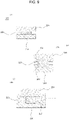
FIG. 9 is a cross-sectional view showing a pressure sensor according to a preferred embodiment (a), another embodiment (b), and still another embodiment (c). -
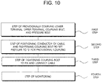
FIG. 10 is a flowchart schematically showing a method for measuring terminal connection or disconnection and pressure according to a preferred embodiment of the present disclosure. -
10 : base frame 12 : installation hole 20 : cable 100 : lower terminal 110 : first coupling hole 200 : pressure sensor 210 : lower insulation 212 : lower mounting recess 220 : sensor 230 : upper insulation 232 : upper mounting recess 300 : upper terminal 310 : body 312: second coupling hole 320 : bent part 330 : separation part 332 : fastening hole 340 : first reinforcing bead 350 : second reinforcing bead 400 : coupling bolt 500 : pressure bolt 600 : controller 700 : display - The present disclosure relates to a system for measuring a coupling force of a pair of terminals, namely, a
lower terminal 100 and anupper terminal 300, for fixing and connecting an electric wire, namely, acable 20, through apressure sensor 200 so as to easily determine a coupling state of thecable 20 fixed between thelower terminal 100 and theupper terminal 300 and to maintain a stable coupling state, specifically, keep the coupling force of thelower terminal 100 and theupper terminal 300 stable. More specifically, disclosed is a technology related to a system for measuring terminal connection or disconnection and pressure by using a pressure sensor and to a method for measuring terminal connection or disconnection and pressure, wherein when between thelower terminal 100 and theupper terminal 300 coupled to abase frame 10 of an electronic device through acoupling bolt 400, a conductor covered by thecable 20 is fixed by the compressive force of theupper terminal 300 and is electrically connected, apressure bolt 500 coupled to theupper terminal 300 by screw-type engagement applies pressure to thepressure sensor 200 provided at thelower terminal 100, so that the compressive force of theupper terminal 300, specifically, the clamping force of thecoupling bolt 400 causing the compressive force of theupper terminal 300 is easily determined through thepressure bolt 500 and thepressure sensor 200, thereby preventing a fire caused by Joule heating that may occur because thecoupling bolt 400 is loosened as time passes. - In order to achieve the present invention as described above, a system for measuring terminal connection or disconnection and pressure by using a pressure sensor includes: a
lower terminal 100 through which afirst coupling hole 110 is formed on a first side thereof, thefirst coupling hole 110 corresponding to aninstallation hole 12 formed in abase frame 10 of an electronic device; thepressure sensor 200 of which a lower part is coupled to an upper part of thelower terminal 100 on a second side thereof; anupper terminal 300 through which asecond coupling hole 312 is formed on a first side thereof and afastening hole 332 is formed on a second side thereof, thesecond coupling hole 312 corresponding to thefirst coupling hole 110 and thefastening hole 332 being at a position corresponding to thepressure sensor 200; acoupling bolt 400 coupled into theinstallation hole 12 of thebase frame 10 by screw-type engagement, passing through thesecond coupling hole 312 of theupper terminal 300 and thefirst coupling hole 110 of thelower terminal 100; and apressure bolt 500 coupled into thefastening hole 332 of theupper terminal 300 by screw-type engagement, and configured to apply pressure to thepressure sensor 200. - In addition, the present disclosure includes: a
controller 600 configured to receive pressure information measured from thepressure sensor 200; and adisplay 700 configured to receive the pressure information from thecontroller 600 and display the pressure information. - In addition, the
upper terminal 300 of the present disclosure includes: abody 310 through which thesecond coupling hole 312 corresponding to thefirst coupling hole 110 is formed; abent part 320 formed extending on a side of thebody 310 and formed in a shape bent upwards in a direction of the side; and aseparation part 330 formed extending on a side of thebent part 320 in a direction of the side, and provided with thefastening hole 332 that is formed at the position corresponding to thepressure sensor 200 and through theseparation part 330. - In addition, the
upper terminal 300 of the present disclosure includes: a first reinforcingbead 340 formed thereon between thebody 310 and thebent part 320; and a plurality of second reinforcingbeads 350 formed starting from a lower surface of thebent part 320 to a lower surface of theseparation part 330. - In addition, the
pressure sensor 200 of the present disclosure includes: alower insulation 210 of which a lower part is coupled to the upper part of thelower terminal 100 on the second side thereof; asensor 220 positioned on thelower insulation 210; and anupper insulation 230 coupled above thelower insulation 210 such that a lower surface of theupper insulation 230 is in contact with thesensor 220. - In addition, in the present disclosure, the
lower insulation 210 is provided with a lower mounting recess 212 in an upper surface thereof, into which a lower part of thesensor 220 is inserted, and theupper insulation 230 is provided with anupper mounting recess 232 in the lower surface thereof, into which an upper part of thesensor 220 is inserted. - In addition, in the present disclosure, the
lower insulation 210 is provided with a lower mounting recess 212 in an upper surface thereof, into which thesensor 220 is inserted, and theupper insulation 230 is coupled as a lower part thereof is inserted into thelower mounting recess 212. - In order to achieve the present invention as described above, a method for measuring terminal connection or disconnection and pressure by using the pressure sensor includes: a first step in which the
lower terminal 100 is positioned on thebase frame 10 of the electronic device, theupper terminal 300 is provisionally coupled above thelower terminal 100 by using thecoupling bolt 400, and thepressure bolt 500 is provisionally coupled to theupper terminal 300; after the first step, a second step in which a conductor of acable 20 is positioned between thelower terminal 100 and theupper terminal 300, thecoupling bolt 400 is tightened to cause theupper terminal 300 to be in contact with the conductor of thecable 20 such that pressure applied to the conductor of thecable 20 by clamping force of thecoupling bolt 400 is 0, and thepressure bolt 500 is tightened to cause a lower part of thepressure bolt 500 to be in contact with an upper part of thepressure sensor 200 such that pressure applied to thepressure sensor 200 is 0; and after the second step, a third step in which thecoupling bolt 400 is tightened to fix the conductor of thecable 20 between thelower terminal 100 and theupper terminal 300, wherein thecoupling bolt 400 is tightened such that pressure caused by thepressure bolt 500 measured by thepressure sensor 200 reaches a preset pressure. - Hereinafter, the present disclosure will be described in detail with reference to
FIGS. 1 to 10 showing embodiments of the present disclosure. - First, a pair of terminals, that is, a
lower terminal 100 and anupper terminal 300, of the present disclosure are coupled to abase frame 10 of an electronic device via acoupling bolt 400, which will be described later. Between thelower terminal 100 and theupper terminal 300, a conductor (not shown) of acable 20 of which a jacket is removed is located, and the conductor of the cable is fixed and is electrically connected by the compressive force of theupper terminal 300, that is, by the clamping force of thecoupling bolt 400, theupper terminal 300 being moved in the direction of thelower terminal 100 by thecoupling bolt 400. - That is, fundamentally, among methods of electrically connecting the
cable 20 by fixing the same, the present disclosure relates to a method of fixing the conductor of thecable 20 by compressive force with which theupper terminal 300 is compressed in the direction of thelower terminal 100 by thecoupling bolt 400. Herein, it is obvious that the clamping force of thecoupling bolt 400 causes compressive force between a terminal and another terminal, specifically, between theupper terminal 300 and thelower terminal 100. - In addition, the
base frame 10 of the electronic device mentioned in the present disclosure is provided inside the electronic device and has a space in which the cable is connected. At thebase frame 10, aninstallation hole 12 into which thecoupling bolt 400, which will be described later, is coupled by screw-type engagement is formed. - In addition, in the present disclosure, in general, a crimp terminal (not shown) is coupled to the conductor of the
cable 20 of which the jacket is stripped to be fixed and coupled to a pair of terminals, but the crimp terminal may not be coupled for quick operation, so it is obvious that the diameter or thickness of the conductor of thecable 20, which will be described later, may correspond to the thickness of the crimp terminal. - The
lower terminal 100, which is a main element for achieving the present disclosure, is
provided with afirst coupling hole 110 that is formed through thelower terminal 100 on a first side thereof. Thefirst coupling hole 110 corresponds to theinstallation hole 12 formed in thebase frame 10 of the electronic device. Thelower terminal 100 is made of a conductor to be electrically connected to the conductor of thecable 20. A thread is formed at the inner circumferential surface of thefirst coupling hole 110 such that thelower terminal 100 is fixed to thebase frame 10 by thecoupling bolt 400, which will be described later, being in contact with thebase frame 10. - In addition, the
lower terminal 100 of the present disclosure is formed extending in length to a second side thereof so that thepressure sensor 200, which will be described later, is provided on thelower terminal 100 on the second side thereof. A coupling hole (not shown) may be formed in the upper surface on the second side so that the lower part of thepressure sensor 200 is mounted therein and coupled thereto, or is coupled thereto by screw-type engagement. - The
pressure sensor 200, which is a main element for achieving the present disclosure, has
the lower part mounted on thelower terminal 100 on the second side thereof, or the lower part coupled and fixed thereto as described above. When thepressure bolt 500, which will be described later, is coupled into thefastening hole 332 of theupper terminal 300 by screw-type engagement and is tightened, the upper surface of thepressure sensor 200 is pressed being in contact with the lower surface of thepressure bolt 500, and the pressure generated by the clamping force of thepressure bolt 500 is measured. - In addition, the
pressure sensor 200 of the present disclosure transmits measured pressure information to thecontroller 600, which will be described later, and thecontroller 600 transmits the pressure information to thedisplay 700, which will be described later, or a user terminal (not shown) so that a user is capable of easily determining the measured pressure. - That is, in the system for measuring terminal connection or disconnection and pressure by using the pressure sensor according to the present disclosure, the pressure information measured by the
pressure sensor 200 is easily determined, so a user is capable of easily determining connection or disconnection between thecable 20 and the terminals. When it is determined that the connection is weakened, specifically, when it is determined that the pressure information is lower than preset pressure information, it is easy to perform maintenance, thereby preventing a fire caused by Joule heating. - Specifically, the
pressure sensor 200 of the present disclosure may include: alower insulation 210 of which the lower part is coupled to the upper part of thelower terminal 100 on the second side thereof; asensor 220 positioned on thelower insulation 210; and anupper insulation 230 coupled above thelower insulation 210 such that the lower surface of theupper insulation 230 is in contact with thesensor 220. - That is, regarding the
pressure sensor 200 of the present disclosure, as theupper insulation 230 is pressed by the clamping force of thepressure bolt 500, which will be described later, and thesensor 220 is thus pressed, thesensor 220 measures the pressure. Thelower insulation 210 insulates and supports thesensor 220, so that the pressure is more stably measured. Accordingly, it is easily determined connection or disconnection between thecable 20 and the terminals, specifically, whether the clamping force of thecoupling bolt 400, which will be described later, is stably formed. - Herein, regarding the detail in which the
upper insulation 230 is coupled to thelower insulation 210, it is obvious that theupper insulation 230 is coupled to thelower insulation 210 such that theupper insulation 230 is pressed by thepressure bolt 500, which will be described, and is movable downwards. - Describing the coupling configuration of the
lower insulation 210 and theupper insulation 230 in more detail, thelower insulation 210 includes alower mounting recess 212 in the upper surface thereof, into which the lower part of thesensor 220 is inserted. The lower part of thesensor 220 is inserted into thelower mounting recess 212 and the upper part protrudes. In the meantime, theupper insulation 230 includes anupper mounting recess 232 in the lower surface thereof, into which the upper part of thesensor 220 is inserted. The upper part of thesensor 220 inserted into theupper mounting recess 232 is pressed by theupper insulation 230 pressed by thepressure bolt 500, which will be described later, and the pressure is measured. - Describing another embodiment of the coupling configuration of the
lower insulation 210 and theupper insulation 230, thelower insulation 210 includes alower mounting recess 212 in the upper surface thereof, into which thesensor 220 is completely inserted. The lower part of theupper insulation 230 is inserted into thelower mounting recess 212 and is coupled. Accordingly, as theupper insulation 230 is pressed by thepressure bolt 500, which will be described later, thesensor 220 provided inside thelower mounting recess 212 of thelower insulation 210 is pressed and the pressure is measured. - Herein, regarding the
pressure sensor 200 of the present disclosure, it is obvious that theupper insulation 230 is coupled to thelower insulation 210 so as to be lifted up and down. In order to stably lift theupper insulation 230 up and down, a rail groove or a rail may be formed in thelower insulation 210. When the rail groove or the rail is formed in thelower insulation 210, a rail or a rail groove corresponding thereto may be formed in theupper insulation 230. - In connection with the above, since the upper surface of the
upper insulation 230 may be damaged by thepressure bolt 500 that is rotated being in contact with the lower surface of thepressure bolt 500, which will be described later, a contact plate (not shown) made of an insulation material having high durability may be further coupled to theupper insulation 230 or theupper insulation 230 may include the contact plate. - The
upper terminal 300, which is a main element for achieving the present disclosure, is
provided with asecond coupling hole 312 that is formed through theupper terminal 300 on a first side thereof and corresponds to thefirst coupling hole 110 of thelower terminal 100, and is also provided with afastening hole 332 that is formed through theupper terminal 300 on a second side thereof, at a position corresponding to the pressure sensor. When thecoupling bolt 400, which will be described later, is coupled to thebase frame 10 and thefirst coupling hole 110 described above by screw-type engagement, passing through thesecond coupling hole 312, the head of thecoupling bolt 400 presses the outside of thesecond coupling hole 312, so that theupper terminal 300 is moved downwards, and accordingly, connection force occurs at the conductor of thecable 20 positioned between thelower terminal 100 and theupper terminal 300. - In addition, after the connection force is generated at the conductor of the
cable 20 by theupper terminal 300 and thelower terminal 100 due to thecoupling bolt 400, thepressure bolt 500, which will be described later, is coupled into thefastening hole 332 by screw-type engagement, and the clamping force causes pressure to thepressure sensor 200 described above and the pressure is measured. - That is, as the
upper terminal 300 of the present disclosure is moved in the direction of thelower terminal 100 by thecoupling bolt 400, which will be described later, in another method, the conductor of thecable 20 positioned between thelower terminal 100 and theupper terminal 300 is pressed and thecable 20 is connected. Regarding the pressure measured by thepressure sensor 200, while the lower surface of theupper terminal 300 is in contact with the conductor of thecable 20 by tightening thecoupling bolt 400, that is, while the conductor of thecable 20 is fixed with the pressure of 0, thepressure bolt 500 is tightened and the lower surface of thepressure bolt 500 is in contact with the upper surface of thepressure sensor 200. When thepressure bolt 500 is tightened with the pressure of 0, thecoupling bolt 400 is tightened again so that the conductor of thecable 20 is firmly fixed. When thepressure sensor 200 measures the pressure caused by thepressure bolt 500, thecontroller 600, which will be described later, stores initial pressure information. - Furthermore, regarding pressure measurement using the
pressure sensor 200 in another method, while the connection force caused by the clamping force formed by thecoupling bolt 400 is stably formed, thepressure bolt 500, which will be described later, is coupled into thefastening hole 332 by screw-type engagement, thepressure sensor 200 is pressed by the clamping force, and thepressure sensor 200 measures the pressure. Thepressure bolt 500 is sufficiently tightened to form clamping force such that the clamping force is similar to the clamping force formed by thecoupling bolt 400 or a pressure preset in thecontroller 600, which will be described, is reached, and pressure information corresponding to an initial connection force is measured by thepressure sensor 200. - Herein, it is obvious that a thread is not formed at the inner circumferential surface of the
second coupling hole 312, so that thecoupling bolt 400 passes through and the head of thecoupling bolt 400 presses theupper terminal 300 downwards. A thread is formed at the inner circumferential surface of thefastening hole 332 such that thepressure bolt 500 is coupled by screw-type engagement. - Specifically, the
upper terminal 300 of the present disclosure may include: abody 310 in which thesecond coupling hole 312 corresponding to thefirst coupling hole 110 is formed through thebody 310; abent part 320 formed extending on a side of the body 310 (the second side of the upper terminal) and formed in a shape that is bent upwards in the direction of the second side of the upper terminal; and aseparation part 330 formed extending on a side of the bent part 320 (the second side of the upper terminal) in the direction of the second side of the upper terminal, and provided with thefastening hole 332 formed through theseparation part 330, at a position corresponding to thepressure sensor 200. - That is, regarding the
upper terminal 300 of the present disclosure, thebody 310 in which thesecond coupling hole 312 is formed is pressed downwards by thecoupling bolt 400, which will be described later, to connect the conductor of thecable 20 positioned between thelower terminal 100 and theupper terminal 300. Thebent part 320 allows theseparation part 330 to be sufficiently spaced apart from the upper surface of thelower terminal 100 on the second side, so that the pressure caused by the clamping force of thepressure bolt 500, which will be described later, is generated smoothly. - Herein, it is preferable that the
bent part 320 is formed in a shape that is bent upwards in the direction of the second side, namely, a curved shape or an arc shape. This is to ensure that the whole of theseparation part 330 is pressed downwards and the pressure caused by the clamping force of thepressure bolt 500 is generated smoothly. Because when the second side of theupper terminal 300, specifically, theseparation part 330, is pressed downwards by thepressure bolt 500, which will be described later, the second side of theupper terminal 300, specifically, only the second side of theseparation part 330, is pressed downwards by the clamping force caused by the screw-type engagement of thepressure bolt 500. - Furthermore, the
upper terminal 330 may further include a first reinforcingbead 340 that is formed at the upper surface between thebody 310 and thebent part 320 in order to prevent thebent part 320 from breaking from thebody 310 when clamping force is generated by thepressure bolt 500 as described above. - As the
pressure bolt 500 is coupled by screw-type engagement, when the lower part of thepressure bolt 500 comes into contact with the upper part of thepressure sensor 200, specifically, the upper surface of theupper insulation 230, the pressure caused by the clamping force is generated. Continuous occurrence of the clamping force may cause a phenomenon that thepressure bolt 500 is not allowed to be moved downwards, theseparation part 330 is moved upwards and thus, thebent part 320 bends upwards and may break. The first reinforcingbead 340 minimizes the phenomenon so that the pressure caused by the clamping force of thepressure bolt 500 is more stably formed. - In addition, the
upper terminal 300 of the present disclosure may include a plurality of second reinforcingbeads 350 formed starting from the lower surface of thebent part 320 to the lower surface of theseparation part 330. The second reinforcingbead 350 enables thebent part 320 and theseparation part 330 to bend together when clamping force is generated by thepressure bolt 500. Thus, theseparation part 330 is prevented from easily breaking from thebent part 320, and simultaneously, the pressure caused by thepressure bolt 500 is stably generated. - The
coupling bolt 400, which is a main element for achieving the present disclosure, is
coupled into theinstallation hole 12 of thebase frame 10 by screw-type engagement, passing through thesecond coupling hole 312 of theupper terminal 300 and thefirst coupling hole 110 of thelower terminal 100. By the clamping force caused by the screw-type engagement, theupper terminal 300 is pressed downwards, so that the conductor of thecable 20 positioned between thelower terminal 100 and theupper terminal 300 is connected and fixed. - Herein, although it has been described that a thread may be formed at the inner circumferential surface of the
first coupling hole 110, since thelower terminal 100 is also pressed together downwards by the conductor of thecable 20 positioned between thelower terminal 100 and theupper terminal 300, it is obvious that a thread does not need to be formed at the inner circumferential surface. In the case in which a thread is formed at the inner circumferential surface, it is preferable that a thread is formed at the inner circumferential surface so that thelower terminal 100 is prevented from moving freely. - That is, as described above, the
coupling bolt 400 of the present disclosure is coupled into theinstallation hole 12 of thebase frame 10 by screw-type engagement and thus presses theupper terminal 300 downwards, so that the conductor of thecable 20 positioned between thelower terminal 100 and theupper terminal 300 is pressed by theupper terminal 300 and fixed, thus causing connection force. - Herein, it is obvious that the
coupling bolt 400 of the present disclosure has different lengths in which screw-type engagement is made according to the diameter or thickness of the conductor of thecable 20. Thepressure bolt 500, which will be described later, also has different lengths in which screw-type engagement is made according to the diameter or thickness of the conductor of thecable 20. - The
pressure bolt 500, which is a main element for achieving the present disclosure, is
coupled into thefastening hole 332 of theupper terminal 300 by screw-type engagement to apply pressure to thepressure sensor 200. As thecoupling bolt 400 presses and fixes the conductor of thecable 20 to connect the same, thepressure sensor 200 is pressed, and thepressure sensor 200 measures the applied pressure of thepressure bolt 500 and provides pressure information to thecontroller 600, which will be described later. - Herein, as described above, the
pressure bolt 500 of the present disclosure may apply pressure to thepressure sensor 200 in another method. Thecoupling bolt 400 presses and fixes the conductor of thecable 20 to connect the same, and is coupled by screw-type engagement, and thepressure sensor 200 is thus pressed by the clamping force. Thepressure sensor 200 measures the applied pressure caused by the clamping force of thepressure bolt 500 and transmits pressure information to thecontroller 600. Thepressure bolt 500 is tightened until the measured pressure reaches a preset pressure. - That is, the
pressure bolt 500 of the present disclosure applies pressure to thepressure sensor 200 as much as an operator uses thecoupling bolt 400 to connect the conductor of thecable 20 between theupper terminal 300 and thelower terminal 100. Alternatively, after an operator uses thecoupling bolt 400 to connect the conductor of thecable 20 between theupper terminal 300 and thelower terminal 100, thepressure bolt 500 is coupled into thefastening hole 332 of theupper terminal 300 and applies pressure to thepressure sensor 200 as much as a preset pressure. - Describing additionally, it is preferable that after the conductor of the
cable 20 is connected between theupper terminal 300 and thelower terminal 100 by using thecoupling bolt 400, thepressure bolt 500 of the present disclosure is coupled into thefastening hole 332 of theupper terminal 300 and thepressure bolt 500 applies pressure to thepressure sensor 200 as much as a preset pressure. This is the latter case. This is because, when thepressure bolt 500 applies pressure, thepressure bolt 500 is rotated because of vibration and the pressure may not be applied as much as the preset pressure in the process of additionally tightening thecoupling bolt 400. - However, according to the above-described method of tightening the
pressure bolt 500 after connecting the conductor of thecable 20 between theupper terminal 300 and thelower terminal 100 by using thecoupling bolt 400, it is difficult to form the same pressure as the applied pressure depending on the thickness of the conductor of thecable 20 caused by thecoupling bolt 400. In practice, in order to measure the same pressure as the pressure applied to the conductor of thecable 20, provisional coupling is made to set the pressure between theupper terminal 300 and the conductor of thecable 20 and the pressure between thepressure bolt 500 and thepressure sensor 200 to 0, and then thecoupling bolt 400 is tightened again, and thepressure sensor 200 measures the pressure caused by the clamping force of thecoupling bolt 400, thereby determining the connection force of the conductor of thecable 20 more accurately. - In connection with the above, the system for measuring terminal connection or disconnection and pressure by using the pressure sensor according to the present disclosure may include the
controller 600 that receives measured pressure information from thepressure sensor 200, specifically, is connected to thesensor 220 and receives the measured pressure information from thesensor 200. - Describing additionally, after the pressure between the
upper terminal 300 and the conductor of thecable 20 and the pressure between thepressure bolt 500 and thepressure sensor 200 are set to 0, thecontroller 600 receives pressure information the same as the pressure of connecting the conductor of thecable 20 by tightening thecoupling bolt 400, from thepressure sensor 200. Alternatively, after the conductor of thecable 20 is connected by tightening thecoupling bolt 400, thepressure bolt 500 is tightened until the preset pressure is applied, and thecontroller 600 receives pressure information from thepressure sensor 200. - The
controller 600 transmits the received pressure information to thedisplay 700, which will be described later, or stores the preset pressure information therein. When the measured pressure, namely, the pressure information, is out of an error range of the initial pressure information or out of an error range of the preset pressure information, thecontroller 600 transmits warning information to thedisplay 700 or a user terminal so that the user or operator is capable of easily determining terminal connection or disconnection. - Herein, it is obvious that the
controller 600 includes a wireless communication part for transmitting the pressure information or warning information to a user terminal (e.g., a portable device). - That is, the system for measuring terminal connection or disconnection and pressure by using the pressure sensor according to the present disclosure may further include a user terminal, such as a portable device, etc., for receiving the pressure information or warning information from the
controller 600 and displaying the same to the user or operator. - In addition, the system for measuring terminal connection or disconnection and pressure by using the pressure sensor according to the present disclosure may include the
display 700 for receiving pressure information from thecontroller 600 and displaying the pressure information. - The
display 700 may receive the measured pressure information and preset stored pressure information from thecontroller 600 and may display the information selectively. When the measured pressure information is out of an error range of initially measured pressure information or preset pressure information, different lighting or color is displayed, whereby the user or operator is capable of easily determining terminal connection or disconnection. - Herein, the
controller 600 may be provided inside the electronic device, and thedisplay 700 may be provided at the outside of the electronic device or provided separately. In the case in which thedisplay 700 is separately provided, when necessary, the user or operator connects the display to thecontroller 600 and determines terminal connection or disconnection, that is, measured pressure information. - In the meantime, the system for measuring terminal connection or disconnection and pressure by using the pressure sensor according to the present disclosure may further include a position detection sensor (not shown) that is provided at the upper surface of the
upper terminal 300, measures the rotation amount of thecoupling bolt 400, and transmits measured rotation amount information to thecontroller 600. - The position detection sensor is provided on the first side or the second side at the upper surface of the
upper terminal 300, is connected to thecontroller 600, and generates rotation amount information of thecoupling bolt 400. Accordingly, thecontroller 600 calculates the pressure generated by one rotation of thecoupling bolt 400 and transmits applied pressure information to thedisplay 700 or the user terminal. After determining the applied pressure information, the operator or user easily rotates thecoupling bolt 400 as much as needed so as to apply pressure, thereby facilitating maintenance. - Herein, the upper part or the whole of the
upper insulation 230 may be made of a transparent material, and it is preferable that the above-described contact plate is made of a transparent material. - Hereinafter, described will be Embodiment 1 and Embodiment 2 of a method for measuring terminal connection or disconnection and pressure by using the system for measuring terminal connection or disconnection and pressure by using the pressure sensor described above.
- Embodiment 1 is a method of tightening the
pressure bolt 500 in advance so that the pressure corresponding to the clamping force caused by thecoupling bolt 400 is generated. - First, in a first step, the
lower terminal 100 is positioned on thebase frame 10 of the electronic device, theupper terminal 300 is provisionally coupled above thelower terminal 100 by using thecoupling bolt 400, and thepressure bolt 500 is provisionally coupled to theupper terminal 300. - In a second step after the first step, the conductor of the
cable 20 is positioned between thelower terminal 100 and theupper terminal 300, and thecoupling bolt 400 is tightened such that the pressure applied to the conductor of thecable 20 by the clamping force of thecoupling bolt 400 is 0, in other words, theupper terminal 300 is in contact with the conductor of thecable 20. In addition, thepressure bolt 500 is tightened to cause the lower part of thepressure bolt 500 to be in contact with the upper part of thepressure sensor 200 such that the pressure applied to thepressure sensor 200 is 0. - That is, the second step corresponds to a pressure measurement preparation step of setting the pressure between the
upper terminal 300 and the conductor of thecable 20 and the pressure between thepressure bolt 500 and thepressure sensor 200 to 0. - In a third step after the second step, the
coupling bolt 400 is tightened to fix the conductor of thecable 20 between thelower terminal 100 and theupper terminal 300 and connect the conductor of thecable 20, wherein thecoupling bolt 400 is tightened such that the pressure caused by thepressure bolt 500 measured by thepressure sensor 200 reaches a preset pressure. - That is, in the third step, the pressure corresponding to the clamping force caused by the
coupling bolt 400 is applied to thepressure sensor 200 by thepressure bolt 500, and the pressure of connecting the conductor of thecable 20 may be measured. - In a fourth step after the third step, terminal connection or disconnection, that is, measured pressure information from the
controller 600, is continuously monitored through thedisplay 700 or the user terminal, and thecoupling bolt 400 is tightened again when maintenance is required. - Embodiment 2 is a method of generating a similar pressure corresponding to the clamping force caused by the
coupling bolt 400, specifically, enabling thepressure sensor 200 to be pressed by thepressure bolt 500 with a preset pressure according to the diameter or thickness of the conductor of thecable 20. - First, in a first step, the
lower terminal 100 is positioned on thebase frame 10 of the electronic device to prepare for later coupling by thecoupling bolt 400. - In a second step after the first step, the
upper terminal 300 is positioned above thelower terminal 100, and thecoupling bolt 400 is first tightened and coupled into theinstallation hole 12 of thebase frame 10 by screw-type engagement passing through thefirst coupling hole 110 of thelower terminal 100 and thesecond coupling hole 312 of theupper terminal 300, so that thelower terminal 100 and theupper terminal 300 are provisionally coupled. - Herein, in the second step, the
upper terminal 300 is movable upwards and downwards by thecoupling bolt 400. - In a third step after the second step, the
upper terminal 300 is spaced apart from thelower terminal 100 and then the conductor of thecable 20 is positioned on one side between thelower terminal 100 and theupper terminal 300, and thecoupling bolt 400 is second tightened to fix the conductor of thecable 20 between thelower terminal 100 and theupper terminal 300. Herein, thecoupling bolt 400 is tightened and connected so that the conductor of thecable 20 is firmly fixed by theupper terminal 300 and thelower terminal 100. - In a fourth step, the
pressure bolt 500 is tightened and coupled into thefastening hole 332 of theupper terminal 300 by screw-type engagement, wherein thepressure bolt 500 is tightened and coupled by screw-type engagement while thedisplay 700 is checked until the preset pressure stored in thecontroller 600 is applied to thepressure sensor 200. While thecable 20 is connected by the clamping force of thecoupling bolt 400, thepressure bolt 500 is tightened until the preset pressure is applied, and the connection state of thecable 20 is determined. - In a fifth step after the fourth step, terminal connection or disconnection, that is, measured pressure information from the
controller 600, is continuously monitored through thedisplay 700 or the user terminal, and thecoupling bolt 400 is tightened again when maintenance is required. - In conclusion, according to the system for measuring terminal connection or disconnection and pressure by using the pressure sensor and the method for measuring terminal connection or disconnection and pressure according to the present disclosure, the conductor of the
cable 20 is connected by using thelower terminal 100, theupper terminal 300, and thecoupling bolt 400, and then thepressure bolt 500 and thepressure sensor 200 are used to easily determine the connected state of the conductor of thecable 20 and enable maintenance, thereby preventing a fire caused by Joule heating due to the loose connection between the conductor of thecable 20 and the terminals. - The present disclosure has been described with reference to the preferred embodiments, and the present disclosure is not limited to the embodiments, and through the embodiments, those skilled in the art to which the present disclosure pertains may make various modifications without departing from the scope of the present disclosure.
Claims (10)
- A system for measuring terminal connection or disconnection and pressure by using a pressure sensor, the system comprising:a lower terminal (100) through which a first coupling hole (110) is formed on a first side thereof, the first coupling hole (110) corresponding to an installation hole (12) formed in a base frame (10) of an electronic device;the pressure sensor (200) of which a lower part is coupled to an upper part of the lower terminal (100) on a second side thereof;an upper terminal (300) through which a second coupling hole (312) is formed on a first side thereof and a fastening hole (332) is formed on a second side thereof, the second coupling hole (312) corresponding to the first coupling hole (110) and the fastening hole (332) being at a position corresponding to the pressure sensor (200);a coupling bolt (400) coupled into the installation hole (12) of the base frame (10) by screw-type engagement, passing through the second coupling hole (312) of the upper terminal (300) and the first coupling hole (110) of the lower terminal (100); anda pressure bolt (500) coupled into the fastening hole (332) of the upper terminal (300) by screw-type engagement, and configured to apply pressure to the pressure sensor (200).
- The system of claim 1, further comprising a controller (600) configured to receive pressure information measured from the pressure sensor (200).
- The system of claim 2, further comprising a display (700) configured to receive the pressure information from the controller (600) and display the pressure information.
- The system of claim 1, wherein the upper terminal (300) comprises:a body (310) through which the second coupling hole (312) corresponding to the first coupling hole(110) is formed;a bent part (320) formed extending on a side of the body (310) and formed in a shape bent upwards in a direction of the side; anda separation part (330) formed extending on a side of the bent part (320) in a direction of the side, and provided with the fastening hole (332) that is formed at the position corresponding to the pressure sensor (200) and through the separation part (330).
- The system of claim 4, wherein the upper terminal (300) comprises a first reinforcing bead (340) formed thereon between the body (310) and the bent part (320).
- The system of claim 5, wherein the upper terminal (300) comprises a plurality of second reinforcing beads (350) formed starting from a lower surface of the bent part (320) to a lower surface of the separation part (330).
- The system of claim 1, wherein the pressure sensor (200) comprises:a lower insulation (210) of which a lower part is coupled to the upper part of the lower terminal (100) on the second side thereof; a sensor (220) positioned on the lower insulation (210); andan upper insulation (230) coupled above the lower insulation (210) such that a lower surface of the upper insulation (230) is in contact with the sensor (220).
- The system of claim 7, wherein the lower insulation (210) is provided with a lower mounting recess (212) in an upper surface thereof, into which a lower part of the sensor (220) is inserted, and
the upper insulation (230) is provided with an upper mounting recess (232) in the lower surface thereof, into which an upper part of the sensor (220) is inserted. - The system of claim 7, wherein the lower insulation (210) is provided with a lower mounting recess (212) in an upper surface thereof, into which the sensor (220) is inserted, and
the upper insulation (230) is coupled as a lower part thereof is inserted into the lower mounting recess (212). - A method for measuring terminal connection or disconnection and pressure by using the system for measuring terminal connection or disconnection and pressure by using the pressure sensor according to any one of claims 1 to 9, the method comprising:a first step in which the lower terminal (100) is positioned on the base frame (10) of the electronic device, the upper terminal (300) is provisionally coupled above the lower terminal (100) by using the coupling bolt (400), and the pressure bolt (500) is provisionally coupled to the upper terminal (300);after the first step, a second step in which a conductor of a cable (20) is positioned between the lower terminal (100) and the upper terminal (300), the coupling bolt (400) is tightened to cause the upper terminal (300) to be in contact with the conductor of the cable (20) such that pressure applied to the conductor of the cable (20) by clamping force of the coupling bolt (400) is 0, and the pressure bolt (500) is tightened to cause a lower part of the pressure bolt (500) to be in contact with an upper part of the pressure sensor (200) such that pressure applied to the pressure sensor (200) is 0; andafter the second step, a third step in which the coupling bolt (400) is tightened to fix the conductor of the cable (20) between the lower terminal (100) and the upper terminal (300), wherein the coupling bolt (400) is tightened such that pressure caused by the pressure bolt (500) measured by the pressure sensor (200) reaches a preset pressure.
Applications Claiming Priority (2)
| Application Number | Priority Date | Filing Date | Title |
|---|---|---|---|
| KR1020200156171A KR102335195B1 (en) | 2020-11-20 | 2020-11-20 | Terminal connection using pressure sensor and pressure measurement system and terminal connection and pressure measurement method |
| PCT/KR2021/012760 WO2022108078A1 (en) | 2020-11-20 | 2021-09-17 | System and method for measuring terminal connection or disconnection and pressure by using pressure sensor |
Publications (3)
| Publication Number | Publication Date |
|---|---|
| EP4080182A1 true EP4080182A1 (en) | 2022-10-26 |
| EP4080182A4 EP4080182A4 (en) | 2024-01-10 |
| EP4080182B1 EP4080182B1 (en) | 2025-03-05 |
Family
ID=78936306
Family Applications (1)
| Application Number | Title | Priority Date | Filing Date |
|---|---|---|---|
| EP21894851.1A Active EP4080182B1 (en) | 2020-11-20 | 2021-09-17 | System and method for measuring terminal connection or disconnection and pressure by using pressure sensor |
Country Status (3)
| Country | Link |
|---|---|
| EP (1) | EP4080182B1 (en) |
| KR (1) | KR102335195B1 (en) |
| WO (1) | WO2022108078A1 (en) |
Family Cites Families (8)
| Publication number | Priority date | Publication date | Assignee | Title |
|---|---|---|---|---|
| JPH0568073U (en) * | 1992-02-20 | 1993-09-10 | 日東工業株式会社 | Conductor connection device |
| JPH0694561A (en) * | 1992-09-11 | 1994-04-05 | Matsushita Electric Ind Co Ltd | Piezoelectric pressure sensor |
| KR19990034800A (en) | 1997-10-30 | 1999-05-15 | 양재신 | One-touch type wire terminal block |
| JP2005203144A (en) * | 2004-01-13 | 2005-07-28 | Furukawa Electric Co Ltd:The | Terminal crimping device |
| JP4699935B2 (en) * | 2006-04-26 | 2011-06-15 | 株式会社日立エンジニアリング・アンド・サービス | Flange fastening monitoring device |
| JP5851163B2 (en) * | 2011-09-07 | 2016-02-03 | 日本電産コパル電子株式会社 | Pressure sensor |
| KR101142893B1 (en) | 2011-10-13 | 2012-05-10 | 제이와이커스텀(주) | Electric wire terminal switchboard |
| JP6027670B1 (en) * | 2015-09-28 | 2016-11-16 | ベクトリックス株式会社 | Method for determining the fastening axial force of a tapping screw and its display device |
-
2020
- 2020-11-20 KR KR1020200156171A patent/KR102335195B1/en active Active
-
2021
- 2021-09-17 WO PCT/KR2021/012760 patent/WO2022108078A1/en not_active Ceased
- 2021-09-17 EP EP21894851.1A patent/EP4080182B1/en active Active
Also Published As
| Publication number | Publication date |
|---|---|
| EP4080182B1 (en) | 2025-03-05 |
| EP4080182A4 (en) | 2024-01-10 |
| KR102335195B1 (en) | 2021-12-06 |
| WO2022108078A1 (en) | 2022-05-27 |
Similar Documents
| Publication | Publication Date | Title |
|---|---|---|
| TWI449281B (en) | Electronic connector | |
| US20210273353A1 (en) | Terminal Board | |
| EP4080182B1 (en) | System and method for measuring terminal connection or disconnection and pressure by using pressure sensor | |
| JP4808674B2 (en) | SPD for power supply | |
| US20110001941A1 (en) | Lamp housing unit | |
| JP2001235527A (en) | Automatic wire connection | |
| JP2009139170A (en) | Fretting corrosion test equipment | |
| JP2021131949A (en) | Receptacle connector and manufacturing method thereof | |
| JP4601486B2 (en) | Busbar mounting structure | |
| JP4221095B2 (en) | Compact low pressure discharge lamp | |
| US11597065B2 (en) | Pressure measuring device for crimping tool | |
| JP2005106800A5 (en) | ||
| US20050136730A1 (en) | Electric terminal connector block and tooling ensuring terminal insertion | |
| JP2003303647A (en) | Contact for coaxial connector and coaxial connector having the same | |
| KR100823688B1 (en) | Cutting device and its control method | |
| JP2022189042A (en) | Watt-hour meter | |
| JP4698300B2 (en) | Connection structure and connection method between electrical connection member and electrical contact | |
| KR20070101543A (en) | Voltage measuring probe device | |
| KR102127255B1 (en) | Connector assembly for sensor of vehicle | |
| KR200477492Y1 (en) | Compression apparatus for terminal | |
| KR960005894Y1 (en) | Circuit breaker | |
| JPH0728706Y2 (en) | Conductive connection device | |
| JPH0741087Y2 (en) | Connection terminal device | |
| JPH04319269A (en) | Terminal block apparatus | |
| US1033498A (en) | Spark-plug tester. |
Legal Events
| Date | Code | Title | Description |
|---|---|---|---|
| STAA | Information on the status of an ep patent application or granted ep patent |
Free format text: STATUS: THE INTERNATIONAL PUBLICATION HAS BEEN MADE |
|
| PUAI | Public reference made under article 153(3) epc to a published international application that has entered the european phase |
Free format text: ORIGINAL CODE: 0009012 |
|
| STAA | Information on the status of an ep patent application or granted ep patent |
Free format text: STATUS: REQUEST FOR EXAMINATION WAS MADE |
|
| 17P | Request for examination filed |
Effective date: 20220722 |
|
| AK | Designated contracting states |
Kind code of ref document: A1 Designated state(s): AL AT BE BG CH CY CZ DE DK EE ES FI FR GB GR HR HU IE IS IT LI LT LU LV MC MK MT NL NO PL PT RO RS SE SI SK SM TR |
|
| REG | Reference to a national code |
Ref country code: DE Ref legal event code: R079 Free format text: PREVIOUS MAIN CLASS: G01L0003140000 Ipc: H01R0004300000 Ref country code: DE Ref legal event code: R079 Ref document number: 602021027335 Country of ref document: DE Free format text: PREVIOUS MAIN CLASS: G01L0003140000 Ipc: H01R0004300000 |
|
| A4 | Supplementary search report drawn up and despatched |
Effective date: 20231212 |
|
| RIC1 | Information provided on ipc code assigned before grant |
Ipc: G01L 1/04 20060101ALI20231206BHEP Ipc: H01R 4/30 20060101AFI20231206BHEP |
|
| DAV | Request for validation of the european patent (deleted) | ||
| DAX | Request for extension of the european patent (deleted) | ||
| GRAP | Despatch of communication of intention to grant a patent |
Free format text: ORIGINAL CODE: EPIDOSNIGR1 |
|
| STAA | Information on the status of an ep patent application or granted ep patent |
Free format text: STATUS: GRANT OF PATENT IS INTENDED |
|
| INTG | Intention to grant announced |
Effective date: 20240731 |
|
| GRAJ | Information related to disapproval of communication of intention to grant by the applicant or resumption of examination proceedings by the epo deleted |
Free format text: ORIGINAL CODE: EPIDOSDIGR1 |
|
| STAA | Information on the status of an ep patent application or granted ep patent |
Free format text: STATUS: REQUEST FOR EXAMINATION WAS MADE |
|
| GRAS | Grant fee paid |
Free format text: ORIGINAL CODE: EPIDOSNIGR3 |
|
| STAA | Information on the status of an ep patent application or granted ep patent |
Free format text: STATUS: GRANT OF PATENT IS INTENDED |
|
| GRAP | Despatch of communication of intention to grant a patent |
Free format text: ORIGINAL CODE: EPIDOSNIGR1 |
|
| INTC | Intention to grant announced (deleted) | ||
| INTG | Intention to grant announced |
Effective date: 20241127 |
|
| GRAA | (expected) grant |
Free format text: ORIGINAL CODE: 0009210 |
|
| STAA | Information on the status of an ep patent application or granted ep patent |
Free format text: STATUS: THE PATENT HAS BEEN GRANTED |
|
| AK | Designated contracting states |
Kind code of ref document: B1 Designated state(s): AL AT BE BG CH CY CZ DE DK EE ES FI FR GB GR HR HU IE IS IT LI LT LU LV MC MK MT NL NO PL PT RO RS SE SI SK SM TR |
|
| REG | Reference to a national code |
Ref country code: GB Ref legal event code: FG4D |
|
| REG | Reference to a national code |
Ref country code: CH Ref legal event code: EP |
|
| REG | Reference to a national code |
Ref country code: IE Ref legal event code: FG4D |
|
| REG | Reference to a national code |
Ref country code: DE Ref legal event code: R096 Ref document number: 602021027335 Country of ref document: DE |
|
| PG25 | Lapsed in a contracting state [announced via postgrant information from national office to epo] |
Ref country code: RS Free format text: LAPSE BECAUSE OF FAILURE TO SUBMIT A TRANSLATION OF THE DESCRIPTION OR TO PAY THE FEE WITHIN THE PRESCRIBED TIME-LIMIT Effective date: 20250605 |
|
| PG25 | Lapsed in a contracting state [announced via postgrant information from national office to epo] |
Ref country code: FI Free format text: LAPSE BECAUSE OF FAILURE TO SUBMIT A TRANSLATION OF THE DESCRIPTION OR TO PAY THE FEE WITHIN THE PRESCRIBED TIME-LIMIT Effective date: 20250305 |
|
| REG | Reference to a national code |
Ref country code: NL Ref legal event code: MP Effective date: 20250305 |
|
| PG25 | Lapsed in a contracting state [announced via postgrant information from national office to epo] |
Ref country code: ES Free format text: LAPSE BECAUSE OF FAILURE TO SUBMIT A TRANSLATION OF THE DESCRIPTION OR TO PAY THE FEE WITHIN THE PRESCRIBED TIME-LIMIT Effective date: 20250305 |
|
| REG | Reference to a national code |
Ref country code: LT Ref legal event code: MG9D |
|
| PG25 | Lapsed in a contracting state [announced via postgrant information from national office to epo] |
Ref country code: NO Free format text: LAPSE BECAUSE OF FAILURE TO SUBMIT A TRANSLATION OF THE DESCRIPTION OR TO PAY THE FEE WITHIN THE PRESCRIBED TIME-LIMIT Effective date: 20250605 |
|
| PG25 | Lapsed in a contracting state [announced via postgrant information from national office to epo] |
Ref country code: HR Free format text: LAPSE BECAUSE OF FAILURE TO SUBMIT A TRANSLATION OF THE DESCRIPTION OR TO PAY THE FEE WITHIN THE PRESCRIBED TIME-LIMIT Effective date: 20250305 |
|
| PG25 | Lapsed in a contracting state [announced via postgrant information from national office to epo] |
Ref country code: LV Free format text: LAPSE BECAUSE OF FAILURE TO SUBMIT A TRANSLATION OF THE DESCRIPTION OR TO PAY THE FEE WITHIN THE PRESCRIBED TIME-LIMIT Effective date: 20250305 |
|
| PG25 | Lapsed in a contracting state [announced via postgrant information from national office to epo] |
Ref country code: GR Free format text: LAPSE BECAUSE OF FAILURE TO SUBMIT A TRANSLATION OF THE DESCRIPTION OR TO PAY THE FEE WITHIN THE PRESCRIBED TIME-LIMIT Effective date: 20250606 Ref country code: BG Free format text: LAPSE BECAUSE OF FAILURE TO SUBMIT A TRANSLATION OF THE DESCRIPTION OR TO PAY THE FEE WITHIN THE PRESCRIBED TIME-LIMIT Effective date: 20250305 |
|
| REG | Reference to a national code |
Ref country code: AT Ref legal event code: MK05 Ref document number: 1773840 Country of ref document: AT Kind code of ref document: T Effective date: 20250305 |
|
| PG25 | Lapsed in a contracting state [announced via postgrant information from national office to epo] |
Ref country code: NL Free format text: LAPSE BECAUSE OF FAILURE TO SUBMIT A TRANSLATION OF THE DESCRIPTION OR TO PAY THE FEE WITHIN THE PRESCRIBED TIME-LIMIT Effective date: 20250305 |
|
| PG25 | Lapsed in a contracting state [announced via postgrant information from national office to epo] |
Ref country code: SE Free format text: LAPSE BECAUSE OF FAILURE TO SUBMIT A TRANSLATION OF THE DESCRIPTION OR TO PAY THE FEE WITHIN THE PRESCRIBED TIME-LIMIT Effective date: 20250305 |
|
| PG25 | Lapsed in a contracting state [announced via postgrant information from national office to epo] |
Ref country code: SM Free format text: LAPSE BECAUSE OF FAILURE TO SUBMIT A TRANSLATION OF THE DESCRIPTION OR TO PAY THE FEE WITHIN THE PRESCRIBED TIME-LIMIT Effective date: 20250305 |
|
| PG25 | Lapsed in a contracting state [announced via postgrant information from national office to epo] |
Ref country code: PT Free format text: LAPSE BECAUSE OF FAILURE TO SUBMIT A TRANSLATION OF THE DESCRIPTION OR TO PAY THE FEE WITHIN THE PRESCRIBED TIME-LIMIT Effective date: 20250707 |
|
| PGFP | Annual fee paid to national office [announced via postgrant information from national office to epo] |
Ref country code: DE Payment date: 20250702 Year of fee payment: 5 |
|
| PG25 | Lapsed in a contracting state [announced via postgrant information from national office to epo] |
Ref country code: PL Free format text: LAPSE BECAUSE OF FAILURE TO SUBMIT A TRANSLATION OF THE DESCRIPTION OR TO PAY THE FEE WITHIN THE PRESCRIBED TIME-LIMIT Effective date: 20250305 Ref country code: IT Free format text: LAPSE BECAUSE OF FAILURE TO SUBMIT A TRANSLATION OF THE DESCRIPTION OR TO PAY THE FEE WITHIN THE PRESCRIBED TIME-LIMIT Effective date: 20250305 |
|
| PG25 | Lapsed in a contracting state [announced via postgrant information from national office to epo] |
Ref country code: AT Free format text: LAPSE BECAUSE OF FAILURE TO SUBMIT A TRANSLATION OF THE DESCRIPTION OR TO PAY THE FEE WITHIN THE PRESCRIBED TIME-LIMIT Effective date: 20250305 |
|
| PG25 | Lapsed in a contracting state [announced via postgrant information from national office to epo] |
Ref country code: EE Free format text: LAPSE BECAUSE OF FAILURE TO SUBMIT A TRANSLATION OF THE DESCRIPTION OR TO PAY THE FEE WITHIN THE PRESCRIBED TIME-LIMIT Effective date: 20250305 Ref country code: CZ Free format text: LAPSE BECAUSE OF FAILURE TO SUBMIT A TRANSLATION OF THE DESCRIPTION OR TO PAY THE FEE WITHIN THE PRESCRIBED TIME-LIMIT Effective date: 20250305 |
|
| PG25 | Lapsed in a contracting state [announced via postgrant information from national office to epo] |
Ref country code: RO Free format text: LAPSE BECAUSE OF FAILURE TO SUBMIT A TRANSLATION OF THE DESCRIPTION OR TO PAY THE FEE WITHIN THE PRESCRIBED TIME-LIMIT Effective date: 20250305 |
|
| PG25 | Lapsed in a contracting state [announced via postgrant information from national office to epo] |
Ref country code: SK Free format text: LAPSE BECAUSE OF FAILURE TO SUBMIT A TRANSLATION OF THE DESCRIPTION OR TO PAY THE FEE WITHIN THE PRESCRIBED TIME-LIMIT Effective date: 20250305 |
|
| PG25 | Lapsed in a contracting state [announced via postgrant information from national office to epo] |
Ref country code: IS Free format text: LAPSE BECAUSE OF FAILURE TO SUBMIT A TRANSLATION OF THE DESCRIPTION OR TO PAY THE FEE WITHIN THE PRESCRIBED TIME-LIMIT Effective date: 20250705 |
|
| REG | Reference to a national code |
Ref country code: DE Ref legal event code: R097 Ref document number: 602021027335 Country of ref document: DE |
|
| PLBE | No opposition filed within time limit |
Free format text: ORIGINAL CODE: 0009261 |
|
| STAA | Information on the status of an ep patent application or granted ep patent |
Free format text: STATUS: NO OPPOSITION FILED WITHIN TIME LIMIT |
|
| PG25 | Lapsed in a contracting state [announced via postgrant information from national office to epo] |
Ref country code: DK Free format text: LAPSE BECAUSE OF FAILURE TO SUBMIT A TRANSLATION OF THE DESCRIPTION OR TO PAY THE FEE WITHIN THE PRESCRIBED TIME-LIMIT Effective date: 20250305 |
|
| REG | Reference to a national code |
Ref country code: CH Ref legal event code: L10 Free format text: ST27 STATUS EVENT CODE: U-0-0-L10-L00 (AS PROVIDED BY THE NATIONAL OFFICE) Effective date: 20260114 |
|
| 26N | No opposition filed |
Effective date: 20251208 |
|
| REG | Reference to a national code |
Ref country code: CH Ref legal event code: H13 Free format text: ST27 STATUS EVENT CODE: U-0-0-H10-H13 (AS PROVIDED BY THE NATIONAL OFFICE) Effective date: 20260504 |
|
| PG25 | Lapsed in a contracting state [announced via postgrant information from national office to epo] |
Ref country code: LU Free format text: LAPSE BECAUSE OF NON-PAYMENT OF DUE FEES Effective date: 20250917 |
|
| GBPC | Gb: european patent ceased through non-payment of renewal fee |
Effective date: 20250917 |
|
| REG | Reference to a national code |
Ref country code: BE Ref legal event code: MM Effective date: 20250930 |
|
| PG25 | Lapsed in a contracting state [announced via postgrant information from national office to epo] |
Ref country code: LT Free format text: LAPSE BECAUSE OF FAILURE TO SUBMIT A TRANSLATION OF THE DESCRIPTION OR TO PAY THE FEE WITHIN THE PRESCRIBED TIME-LIMIT Effective date: 20250305 |
|
| PG25 | Lapsed in a contracting state [announced via postgrant information from national office to epo] |
Ref country code: MC Free format text: LAPSE BECAUSE OF FAILURE TO SUBMIT A TRANSLATION OF THE DESCRIPTION OR TO PAY THE FEE WITHIN THE PRESCRIBED TIME-LIMIT Effective date: 20250305 |
|
| PG25 | Lapsed in a contracting state [announced via postgrant information from national office to epo] |
Ref country code: GB Free format text: LAPSE BECAUSE OF NON-PAYMENT OF DUE FEES Effective date: 20250917 |
|
| PG25 | Lapsed in a contracting state [announced via postgrant information from national office to epo] |
Ref country code: IE Free format text: LAPSE BECAUSE OF NON-PAYMENT OF DUE FEES Effective date: 20250917 Ref country code: CH Free format text: LAPSE BECAUSE OF NON-PAYMENT OF DUE FEES Effective date: 20250930 Ref country code: BE Free format text: LAPSE BECAUSE OF NON-PAYMENT OF DUE FEES Effective date: 20250930 |
|
| PG25 | Lapsed in a contracting state [announced via postgrant information from national office to epo] |
Ref country code: FR Free format text: LAPSE BECAUSE OF NON-PAYMENT OF DUE FEES Effective date: 20250930 |