EP4080174A1 - Wearable environmental sensor device - Google Patents
Wearable environmental sensor device Download PDFInfo
- Publication number
- EP4080174A1 EP4080174A1 EP19956801.5A EP19956801A EP4080174A1 EP 4080174 A1 EP4080174 A1 EP 4080174A1 EP 19956801 A EP19956801 A EP 19956801A EP 4080174 A1 EP4080174 A1 EP 4080174A1
- Authority
- EP
- European Patent Office
- Prior art keywords
- sensor
- environmental sensor
- substrate
- environmental
- temperature
- Prior art date
- Legal status (The legal status is an assumption and is not a legal conclusion. Google has not performed a legal analysis and makes no representation as to the accuracy of the status listed.)
- Granted
Links
Images




Classifications
-
- A—HUMAN NECESSITIES
- A61—MEDICAL OR VETERINARY SCIENCE; HYGIENE
- A61B—DIAGNOSIS; SURGERY; IDENTIFICATION
- A61B5/00—Measuring for diagnostic purposes; Identification of persons
- A61B5/24—Detecting, measuring or recording bioelectric or biomagnetic signals of the body or parts thereof
- A61B5/316—Modalities, i.e. specific diagnostic methods
- A61B5/318—Heart-related electrical modalities, e.g. electrocardiography [ECG]
- A61B5/332—Portable devices specially adapted therefor
-
- G—PHYSICS
- G01—MEASURING; TESTING
- G01K—MEASURING TEMPERATURE; MEASURING QUANTITY OF HEAT; THERMALLY-SENSITIVE ELEMENTS NOT OTHERWISE PROVIDED FOR
- G01K1/00—Details of thermometers not specially adapted for particular types of thermometer
- G01K1/08—Protective devices, e.g. casings
-
- G—PHYSICS
- G01—MEASURING; TESTING
- G01J—MEASUREMENT OF INTENSITY, VELOCITY, SPECTRAL CONTENT, POLARISATION, PHASE OR PULSE CHARACTERISTICS OF INFRARED, VISIBLE OR ULTRAVIOLET LIGHT; COLORIMETRY; RADIATION PYROMETRY
- G01J5/00—Radiation pyrometry, e.g. infrared or optical thermometry
- G01J5/02—Constructional details
- G01J5/0205—Mechanical elements; Supports for optical elements
-
- G—PHYSICS
- G01—MEASURING; TESTING
- G01J—MEASUREMENT OF INTENSITY, VELOCITY, SPECTRAL CONTENT, POLARISATION, PHASE OR PULSE CHARACTERISTICS OF INFRARED, VISIBLE OR ULTRAVIOLET LIGHT; COLORIMETRY; RADIATION PYROMETRY
- G01J5/00—Radiation pyrometry, e.g. infrared or optical thermometry
- G01J5/02—Constructional details
- G01J5/0265—Handheld, portable
-
- G—PHYSICS
- G01—MEASURING; TESTING
- G01J—MEASUREMENT OF INTENSITY, VELOCITY, SPECTRAL CONTENT, POLARISATION, PHASE OR PULSE CHARACTERISTICS OF INFRARED, VISIBLE OR ULTRAVIOLET LIGHT; COLORIMETRY; RADIATION PYROMETRY
- G01J5/00—Radiation pyrometry, e.g. infrared or optical thermometry
- G01J5/02—Constructional details
- G01J5/04—Casings
- G01J5/046—Materials; Selection of thermal materials
-
- G—PHYSICS
- G01—MEASURING; TESTING
- G01J—MEASUREMENT OF INTENSITY, VELOCITY, SPECTRAL CONTENT, POLARISATION, PHASE OR PULSE CHARACTERISTICS OF INFRARED, VISIBLE OR ULTRAVIOLET LIGHT; COLORIMETRY; RADIATION PYROMETRY
- G01J5/00—Radiation pyrometry, e.g. infrared or optical thermometry
- G01J5/02—Constructional details
- G01J5/04—Casings
- G01J5/048—Protective parts
-
- G—PHYSICS
- G01—MEASURING; TESTING
- G01J—MEASUREMENT OF INTENSITY, VELOCITY, SPECTRAL CONTENT, POLARISATION, PHASE OR PULSE CHARACTERISTICS OF INFRARED, VISIBLE OR ULTRAVIOLET LIGHT; COLORIMETRY; RADIATION PYROMETRY
- G01J5/00—Radiation pyrometry, e.g. infrared or optical thermometry
- G01J5/02—Constructional details
- G01J5/06—Arrangements for eliminating effects of disturbing radiation; Arrangements for compensating changes in sensitivity
-
- G—PHYSICS
- G01—MEASURING; TESTING
- G01J—MEASUREMENT OF INTENSITY, VELOCITY, SPECTRAL CONTENT, POLARISATION, PHASE OR PULSE CHARACTERISTICS OF INFRARED, VISIBLE OR ULTRAVIOLET LIGHT; COLORIMETRY; RADIATION PYROMETRY
- G01J5/00—Radiation pyrometry, e.g. infrared or optical thermometry
- G01J5/52—Radiation pyrometry, e.g. infrared or optical thermometry using comparison with reference sources, e.g. disappearing-filament pyrometer
- G01J5/53—Reference sources, e.g. standard lamps; Black bodies
-
- G—PHYSICS
- G01—MEASURING; TESTING
- G01K—MEASURING TEMPERATURE; MEASURING QUANTITY OF HEAT; THERMALLY-SENSITIVE ELEMENTS NOT OTHERWISE PROVIDED FOR
- G01K1/00—Details of thermometers not specially adapted for particular types of thermometer
- G01K1/02—Means for indicating or recording specially adapted for thermometers
- G01K1/024—Means for indicating or recording specially adapted for thermometers for remote indication
-
- G—PHYSICS
- G01—MEASURING; TESTING
- G01K—MEASURING TEMPERATURE; MEASURING QUANTITY OF HEAT; THERMALLY-SENSITIVE ELEMENTS NOT OTHERWISE PROVIDED FOR
- G01K1/00—Details of thermometers not specially adapted for particular types of thermometer
- G01K1/14—Supports; Fastening devices; Arrangements for mounting thermometers in particular locations
-
- G—PHYSICS
- G01—MEASURING; TESTING
- G01W—METEOROLOGY
- G01W1/00—Meteorology
- G01W1/02—Instruments for indicating weather conditions by measuring two or more variables, e.g. humidity, pressure, temperature, cloud cover or wind speed
-
- G—PHYSICS
- G01—MEASURING; TESTING
- G01W—METEOROLOGY
- G01W1/00—Meteorology
- G01W1/11—Weather houses or other ornaments for indicating humidity
-
- G—PHYSICS
- G01—MEASURING; TESTING
- G01W—METEOROLOGY
- G01W1/00—Meteorology
- G01W1/17—Catathermometers for measuring "cooling value" related either to weather conditions or to comfort of other human environment
-
- A—HUMAN NECESSITIES
- A61—MEDICAL OR VETERINARY SCIENCE; HYGIENE
- A61B—DIAGNOSIS; SURGERY; IDENTIFICATION
- A61B2560/00—Constructional details of operational features of apparatus; Accessories for medical measuring apparatus
- A61B2560/02—Operational features
- A61B2560/0242—Operational features adapted to measure environmental factors, e.g. temperature, pollution
-
- A—HUMAN NECESSITIES
- A61—MEDICAL OR VETERINARY SCIENCE; HYGIENE
- A61B—DIAGNOSIS; SURGERY; IDENTIFICATION
- A61B5/00—Measuring for diagnostic purposes; Identification of persons
- A61B5/103—Measuring devices for testing the shape, pattern, colour, size or movement of the body or parts thereof, for diagnostic purposes
- A61B5/11—Measuring movement of the entire body or parts thereof, e.g. head or hand tremor or mobility of a limb
-
- A—HUMAN NECESSITIES
- A61—MEDICAL OR VETERINARY SCIENCE; HYGIENE
- A61B—DIAGNOSIS; SURGERY; IDENTIFICATION
- A61B5/00—Measuring for diagnostic purposes; Identification of persons
- A61B5/24—Detecting, measuring or recording bioelectric or biomagnetic signals of the body or parts thereof
- A61B5/316—Modalities, i.e. specific diagnostic methods
- A61B5/318—Heart-related electrical modalities, e.g. electrocardiography [ECG]
-
- A—HUMAN NECESSITIES
- A61—MEDICAL OR VETERINARY SCIENCE; HYGIENE
- A61B—DIAGNOSIS; SURGERY; IDENTIFICATION
- A61B5/00—Measuring for diagnostic purposes; Identification of persons
- A61B5/68—Arrangements of detecting, measuring or recording means, e.g. sensors, in relation to patient
- A61B5/6801—Arrangements of detecting, measuring or recording means, e.g. sensors, in relation to patient specially adapted to be attached to or worn on the body surface
- A61B5/6802—Sensor mounted on worn items
- A61B5/6804—Garments; Clothes
Definitions
- the present invention relates to a wearable environmental sensor device for measuring environmental information regarding in the vicinity of a location where the device is worn, and in particular to a wearable environmental sensor device that is worn on clothing, a human body, or the like to measure information regarding the environment inside clothing of a wearer.
- heat index meters conventionally used to prevent heat stroke measure black-bulb temperature, wet-bulb temperature, and dry-bulb temperature to obtain a heat index, and a method is used in which the heat index is used as a guide of behavior; e.g., avoiding going out or doing strenuous work when the heat index is relatively high (see NPL 1).
- a conventional heat index meter generally consists of a relatively large device, and it is difficult to place the device in any given location.
- the heat index released by the Ministry of the Environment is a value that represents a wide area.
- the actual heat load received by each individual is greatly influenced by the local environment.
- the environment varies greatly depending on where each person is, such as outdoors or indoors, in the sun or in the shade, on the grass or on the concrete.
- the influence of radiation from the ground is greatly different between a tall adult and a short child.
- the environment of the human body also varies greatly depending on the clothing worn, the state of movement, the state of perspiration, and so on.
- a method of carrying and wearing an environmental sensor is conceivable to monitor the environment in a desired place, particularly in the vicinity of a human body, but conventional WBGT meters or environmental sensors are too large in size to wear and inconvenient to carry, and there may be restrictions on the location where the sensor is worn.
- a small wearable environmental sensor device has not been known that can be attached onto individual's clothing or to the inside thereof and measure the environment in the immediate vicinity of the individual's clothing or the environment within the clothing.
- An object of the present invention is to measure the environment in the vicinity of a human body or the like accurately, easily, and stably.
- a wearable environmental sensor device includes: an environmental sensor arranged on a wall surface of a housing including a sealed section, the wall being in contact with an environment; and a protective structure formed around the environmental sensor, wherein the protective structure includes a plurality of ventilating holes, a sensor surface of the environmental sensor is arranged to face an opening of at least one of the ventilating holes, and an attaching part for attaching the environmental sensor to the wall surface comes into contact only with an edge of a sensor substrate of the environmental sensor and with a portion of a back face of the sensor substrate.
- a wearable environmental sensor device (hereinafter referred to as an “environmental sensor device") 100 according to the first embodiment of the present invention will be described with reference to Figs. 1 to 5 .
- Fig. 1 shows external views of the environmental sensor device 100 according to the present embodiment.
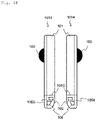
- Fig. 1A is an external view of a front side 1011 and a back side 1012 of the environmental sensor device 100.
- Fig. 1B is an external view of a right side face 1013 and a left side face 1014.
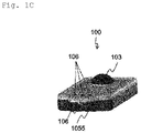
- Fig. 1C is a perspective view.
- the environmental sensor device 100 has, in a housing 101, a temperature and humidity sensor 102 capable of measuring air temperature and relative humidity, and has, on a front face 101A of the housing 101, a black-bulb temperature sensor 103 for measuring black-bulb temperature.
- a lid 108 for battery replacement is provided in a back face 101B of the housing 101.
- the environmental sensor device 100 includes a sealed section 104 and a protective structure (unsealed section) 105.
- the sealed section 104 is sealed, and the sealed section 104 and the protective structure (unsealed section) 105 are separated by a housing wall 101C within the housing 101.
- the size of the environmental sensor device 100 is about 50 mm in length, about 24 mm in width, and about 7 mm in thickness.
- the temperature and humidity sensor 102 is mounted on a substrate (hereinafter referred to as "sensor substrate") 1021, and the surface of the temperature and humidity sensor 102 on the side on which the temperature and humidity sensor 102 is mounted on the sensor substrate 1021 is referred to as a "sensor surface” 1022.
- the temperature and humidity sensor 102 is arranged within the protective structure (unsealed section) 105, and is covered by the protective structure (unsealed section) for protecting the temperature and humidity sensor 102.
- the protective structure (unsealed section) has a function of preventing the temperature and humidity sensor 102 from colliding with an external object and being damaged, and preventing a human finger or the like from coming into contact with the surface (sensor surface 1022) of the temperature and humidity sensor 102 and making the sensor surface (sensor surface 1022) dirty.
- the protective structure (unsealed section) 105 is provided with ventilating holes 106.
- the ventilating holes which have openings in a front face 1051, a back face 1052, a right side face 1053, a left side face 1054, and a lower end face 1055 of the protective structure (unsealed section) 105, penetrate so that each of all the openings is connected to the other openings.
- outside air favorably flows in through the ventilating holes, and thus the temperature and humidity sensor 102 can come into contact with the outside air and measure temperature and humidity of the surrounding air.
- the openings need only be provided in some of these faces, rather than all of the faces, and any configuration may be employed as long as outside air favorably flows in through the ventilating holes.
- the temperature and humidity sensor 102 is arranged such that the sensor surface 1022 faces the opening in the lower end face 1055. Accordingly, a structure in which the sensor surface 1022 is easily exposed to airflow is formed.
- the temperature and humidity sensor 102 is arranged such that the sensor surface 1022 faces the opening in the lower end face 1055, the sensor surface 1022 may face the opening in any face other than the lower end face 1055, and the temperature and humidity sensor 102 need only be arranged such that the sensor surface 1022 faces at least one of the openings.
- the protective structure 105 also includes the openings of the ventilating holes 106 that oppose the left and right side faces 1013 and 1014, and the temperature and humidity sensor 102 is arranged above upper ends of the openings of the ventilating holes 106 (on the sealed section side).
- a structure is formed in which changes in temperature and humidity due to ventilation can be perceived and that is not exposed to water droplets coming from sweat or the like. Accordingly, it is possible to suppress a degradation of measurement accuracy of the temperature and humidity sensor 102 due to water droplets being attached to the sensor surface 1022 and adverse effects such as a humidity value being observed higher than the actual humidity value.
- the housing 101 is lightweight since it is wearable. It is also desirable that the housing 101 has low heat conduction such that heat is not transferred between the black-bulb temperature sensor 103, the housing 101, and the temperature and humidity sensor 102. For this reason, it is desirable that the material of the black bulb and the housing 101 is synthetic resin such as plastic, except for a region where metal needs to be used.
- the black bulb is formed of a synthetic resin such as plastic for weight reduction, and is firmly bonded to the housing 101 by means of welding using ultrasound or the like, for example, The black bulb and the housing 101 are sealed by means of welding to form a dustproof and waterproof structure.
- the black bulb is matte black and has an average emissivity of 0.95.
- the black bulb is hollow inside, and a temperature sensor, such as a thermistor or a semiconductor temperature sensor, is inserted into the hollow portion to measure black-bulb temperature.
- the measured value may be corrected as required.
- the diameter of the black bulb is 10 mm, for example.
- Only the battery lid 108 for inserting a button battery is provided in the back face of the housing 101 of the environmental sensor device 100 according to the present embodiment, and the environmental sensor device 100 can be worn by putting it into a pocket of clothing while operating the environmental sensor device 100 using a commercially available button battery.
- a snap button, a clip, or the like may be provided on the back face of the housing 101 to attach the environmental sensor device 100 to clothing or the like.
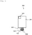
- Fig. 2 shows a mounting substrate 200 within the housing 101 of the environmental sensor device 100.
- the mounting substrate 200 includes a rigid substrate 201 on which a CPU (not shown) and an electronic circuit (not shown) for processing measurement data, and a wireless communication device (wireless communication chip) 203 for transmitting data to an external device are mounted, the sensor substrate 1021 on which the temperature and humidity sensor 102 is mounted, a flexible substrate 202, and a battery (not shown) for operating the temperature and humidity sensor 102.
- the rigid substrate 201 and the battery (not shown) for operating the temperature and humidity sensor 102 are arranged in the sealed section 104, and water, sweat, rain, or the like is prevented from entering from the outside.
- the sealing structure of the sealed section 104 may be constituted by a packing using an O ring or the like, and a screw or the like. If the housing 101 is formed of synthetic resin such as plastic, the sealing structure of the sealed section 104 may be formed by means of welding using ultrasound or the like, or may be formed of an adhesive.
- the temperature and humidity sensor 102 is a sensor for measuring air temperature and relative humidity in the vicinity, is constituted by a semiconductor chip, for example, and includes a temperature sensor in which the resistance varies depending on temperature and a humidity sensor that absorbs moisture of surrounding gas and in which the capacity and resistance vary.
- the temperature and humidity sensor 102 includes an AD conversion circuit, and the measured temperature and humidity are transmitted as digital data to the CPU in the sealed section 104.
- the sensor substrate 1021 of the temperature and humidity sensor 102 is entirely protected by a chemically inactive coating (coating agent) to form a dustproof and waterproof structure. Note that the temperature and humidity sensor 102 itself is also dustproof and waterproof.
- the temperature and humidity sensor 102 on the sensor substrate 1021 arranged in the protective structure (unsealed section) 105 and the CPU on the rigid substrate 201 arranged in the sealed section 104 are electrically connected to each other via the flexible substrate 202.
- the flexible substrate 202 is arranged between the sealed section 104 and the protective structure (unsealed section) 105 such that the sealing property of the sealed section 104 can be maintained by the packing using an O ring or the like, and the screw or the like, at the periphery of the housing wall 101C.
- these parts may alternatively be adhered to each other without gaps using an adhesion, in addition to the aforementioned packing using an O ring or the like, and the screw or the like, and thus dustproof and waterproof properties can be ensured.
- the environmental sensor device 100 has a configuration in which the temperature and humidity sensor 102 that requires contact with outside air is arranged outside the sealed section (i.e., within the protective structure (unsealed section) 105), the rigid substrate 201 on which the CPU, the electronic circuit, and so on for processing signals (digital data) obtained by the temperature and humidity sensor 102 are mounted is arranged in the sealed section 104 to ensure dustproof and waterproof properties, and the temperature and humidity sensor 102 within the protective structure (unsealed section) 105 and the rigid substrate 201 in the sealed section 104 are connected by the flexible substrate 202.
- This configuration enables the temperature and humidity sensor 102 to come into contact with outside air and detect temperature and humidity with high sensitivity, and makes it possible to stably process the detected information (digital data) using the electronic circuit arranged in a sealed environment with excellent dustproof and waterproof properties.
- Fig. 3 shows examples in which the environmental sensor device 100 is attached to outerwear and thus worn and used.
- the outerwear 302 has a pocket, and the housing 101 of the environmental sensor device 100 is inserted into the pocket with the black bulb facing outward.
- the environmental sensor device 100 may be worn at the chest position as in a wearing form 310, or may be worn at the back position as in a wearing form 320.
- a pocket it is desirable that the material of the pocket is a highly moisture-permeable material such as a mesh fabric, in order to improve the response to humidity.
- the environmental sensor device 100 it is possible to easily wear the environmental sensor device 100 at the same time as wearing clothing such as a T-shirt or a polo shirt, and measure environmental information such as temperature and humidity in the vicinity of a human body 301 without disturbing the wearer's movement.
- the environmental sensor device 100 may be attached via a snap button, or a structure such as a clip may be formed on the housing 101 of the environmental sensor device 100 to wear the device by clipping the device onto clothing.
- the environment in the vicinity of a human body can be measured by measuring the influence of solar radiation on the human body using the black-bulb temperature sensor 103, and measuring temperature inside clothing and humidity inside clothing using the temperature and humidity sensor 102.
- the environmental sensor device can also be attached to the outside of outerwear and used as an external environmental sensor device attached to the immediate outside of a human body.
- Figs. 4A , 4B , and 4C are diagrams illustrating the state where the temperature and humidity sensor 102 is attached to the housing 101 within the protective structure (unsealed section) 105.
- Fig. 4A is a perspective view of the substrate (sensor substrate) 1021 with the temperature and humidity sensor 102 mounted thereon, viewed from the back side.
- Fig. 4B is a perspective view of the sensor substrate 1021 viewed from the front side.
- Fig. 4C is a cross-sectional view of an area where the temperature and humidity sensor 102 is attached to the housing 101.
- the housing 101 has, on the front face 101A, a housing wall 101C that is in contact with the environment, and has attaching parts, namely L-shaped parts 401 and protruding parts 402 on an inner wall of the front face 101A.
- the sensor substrate 1021 on which the temperature and humidity sensor 102 is mounted is arranged while being sandwiched or attached between the L-shaped parts 401 and the protruding parts 402.
- the sensor substrate 1021 comes into contact with the L-shaped parts 401 at side faces, which are end faces of the sensor substrate 1021, and at both edges of the sensor substrate 1021.
- the sensor substrate 1021 comes into contact with leading ends of the protruding parts 402 at portions of a back face at both edges of the sensor substrate 1021.
- Attaching contact portions 403 are portions at which the aforementioned attaching parts abut against the sensor substrate 1021.
- the contact area between the sensor substrate 1021 and the attaching parts, namely the L-shaped parts 401 and the protruding parts 402 can be reduced, and the sensor substrate 1021 can be arranged at a position away from the housing 101.
- Air has thermal insulation that is about 7 times higher than that of ordinary plastic (synthetic resin), which is the material of the housing 101, and about 2.5 times higher than that of a thermal insulator. Accordingly, it is possible to realize higher thermal insulation than that of a thermal insulation structure formed by increasing the thickness of the housing 101 or inserting a thermal insulator.
- thermal insulation can be improved and the sensor substrate 1021 can be easily attached to the housing 101 by the structure in which the sensor substrate 1021 is sandwiched or inserted, at the edges thereof, between the L-shaped parts 401 and the protruding parts 402.
- a distance 404 between the back face of the sensor substrate 1021 and the housing 101 is determined by the shape of the protruding parts 402. Since a thermal insulator with a thickness of about 0.5 mm or more is effective in the thermal insulating effect, it is desirable that the distance 404 between the back face of the sensor substrate 1021 and the housing 101, i.e., the thickness of the air layer is 0.2 mm or more, considering that air has high thermal insulation that is about 2.5 times that of the thermal insulator. Further, considering the size of the environmental sensor device 100, it is desirable that the distance 404 between the back face of the sensor substrate 1021 and the housing 101 is 20 mm or less.
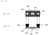
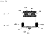
- Figs. 5A and 5B show modes in which the environmental sensor device 100 according to the present variations comes into contact with the protruding parts 402 via guides provided in the temperature and humidity sensor substrate 1021.
- Guide holes 501 and cutout portions 502 are provided as the guides.
- Fig. 5A 51 denotes an upper face of the temperature and humidity sensor substrate 1021, and 52 denotes a side face thereof.
- the guide holes 501 are provided in the sensor substrate 1021, and the protruding parts 402 are inserted into the sensor substrate 1021 via the guide holes 501.
- each protruding part 402 has a tapered structure that is thinner at a leading end thereof so as to be able to be easily inserted into the corresponding guide hole 501, any structure other than the tapered structure may be employed as long as the protruding part 402 can be inserted into the guide hole 501.
- the cross-sectional shape of the guide holes 501 and the protruding parts 402 is a circular shape
- the cross-sectional shape of the guide holes 501 and the protruding parts 402 may be any other shape, such as a square shape, a rectangular shape, a polygonal shape, or an elliptical shape, as long as the guide holes 501 and the protruding parts 402 have corresponding shapes and sizes, and the protruding parts 402 can be inserted into the guide holes 501.
- Fig. 5B 53 denotes an upper face of the temperature and humidity sensor substrate 1021, and 54 denotes a side face thereof.
- the cutout portions 502 are provided in the sensor substrate 1021, and the protruding parts 402 are fitted to the sensor substrate 1021 via the cutout portions 502.
- each cutout portion 502 is a semicircular shape
- the cross-sectional shape of each cutout portion 502 may be any other shape, such as a square shape, a rectangular shape, a polygonal shape, or a semi-elliptical shape, as long as the cutout portions 502 and the protruding parts 402 have corresponding shapes and sizes, and the protruding parts 402 can be fitted to the cutout portions 502.
- each protruding part 402 of the first embodiment comes into contact with the sensor substrate 1021 in a predetermined area.
- the outer circumferential portion of each protruding part 402 simply comes into contact with an end face of an inner wall of the corresponding guide, and it is therefore possible to reduce the contact area between each protruding part 402 and the sensor substrate 1021.
- the effect of facilitating positioning when the sensor substrate 1021 is attached to the housing 101 via the protruding parts 402 is also achieved.
- the sensor substrate 1021 may be arranged in the housing 101 without using the L-shaped parts 401 of the first embodiment, or the L-shaped parts 401 may also be used.
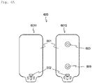
- Fig. 6A shows a front face 6011 and a back face 6012 of an environmental sensor device 600 according to the second embodiment of the present invention.
- the present embodiment has substantially the same configuration as the first embodiment, but is different in that a snap button is provided on the back face 6012 of the housing, and in terms of the configuration of the sensor.
- the environmental sensor device 600 is configured to be attached to a wear or a belt using a snap button 603 attached to the back face 6012 of the housing 601.
- the snap button 603 also functions as an electrode, and can be electrically connected to an electrode for bioelectric potential measurement that is formed in the wear or the belt by being fitted to this electrode to measure bioelectric potential such as electrocardiogram.
- the environmental sensor device 600 includes a rechargeable battery that is built in as an operating power source (not shown).
- Fig. 6B shows a mounting substrate 610 within the housing 601 of the environmental sensor device 600 according to the second embodiment of the present invention.
- the mounting substrate 610 includes a rigid substrate 611, a temperature and humidity sensor 612, a sensor substrate 6121, a flexible substrate 613, a wireless communication device (wireless communication chip) 614, a CPU (not shown), and a circuit board (not shown).
- the mounting substrate 610 has substantially the same configuration as the mounting substrate 200 used in the first embodiment of the present invention, but is different in terms of sensors mounted.
- the mounting substrate 610 includes an AFE (analog front end) 615 that serves as an electrocardiographic waveform sensor to measure and process waveforms, and an acceleration and angular velocity sensor (gyroscope sensor) 616. Accordingly, biological information can be measured at the same time as the environment (temperature and humidity) at the location where the environmental sensor device 600 is worn. Further, a black-bulb temperature sensor can also be provided.
- AFE analog front end
- Gyroscope sensor acceleration and angular velocity sensor
- the same effects as those of the first embodiment are achieved, and the environmental sensor device 600 can be easily attached to a wear or a belt and measure biological information at the same time as the environment (temperature and humidity) of the location where the environmental sensor device 600 is worn.
- the temperature and humidity sensor is used in the environmental sensor device according to the present invention, only a temperature sensor may be used, or only a humidity sensor may be used, and any sensor (hereinafter referred to as an “environmental sensor”) may be employed that comes into contact with the environment, such as outside air, to detect information regarding the environment, such as temperature and humidity.
- an environmental sensor any sensor (hereinafter referred to as an "environmental sensor”) may be employed that comes into contact with the environment, such as outside air, to detect information regarding the environment, such as temperature and humidity.
- the present invention relates to a wearable environmental sensor device to be worn on a human body or the like, and is applicable to measurement of the environment, such as temperature and humidity, in the vicinity of a human body or the like.
Landscapes
- Physics & Mathematics (AREA)
- General Physics & Mathematics (AREA)
- Environmental & Geological Engineering (AREA)
- Life Sciences & Earth Sciences (AREA)
- Spectroscopy & Molecular Physics (AREA)
- Engineering & Computer Science (AREA)
- Health & Medical Sciences (AREA)
- Atmospheric Sciences (AREA)
- Biodiversity & Conservation Biology (AREA)
- Ecology (AREA)
- Environmental Sciences (AREA)
- Heart & Thoracic Surgery (AREA)
- Public Health (AREA)
- Biomedical Technology (AREA)
- Biophysics (AREA)
- Medical Informatics (AREA)
- Molecular Biology (AREA)
- Surgery (AREA)
- Animal Behavior & Ethology (AREA)
- General Health & Medical Sciences (AREA)
- Pathology (AREA)
- Veterinary Medicine (AREA)
- Cardiology (AREA)
- Investigating Or Analyzing Materials By The Use Of Electric Means (AREA)
- Testing Or Calibration Of Command Recording Devices (AREA)
- Measuring Temperature Or Quantity Of Heat (AREA)
- Measuring And Recording Apparatus For Diagnosis (AREA)
- Measuring Fluid Pressure (AREA)
- Measuring Pulse, Heart Rate, Blood Pressure Or Blood Flow (AREA)
Abstract
Description
- The present invention relates to a wearable environmental sensor device for measuring environmental information regarding in the vicinity of a location where the device is worn, and in particular to a wearable environmental sensor device that is worn on clothing, a human body, or the like to measure information regarding the environment inside clothing of a wearer.
- It is important to monitor environmental information for physical condition management, such as prevention of heat stroke in hot weather. For example, heat index meters conventionally used to prevent heat stroke measure black-bulb temperature, wet-bulb temperature, and dry-bulb temperature to obtain a heat index, and a method is used in which the heat index is used as a guide of behavior; e.g., avoiding going out or doing strenuous work when the heat index is relatively high (see NPL 1).
- A conventional heat index meter generally consists of a relatively large device, and it is difficult to place the device in any given location. For example, the heat index released by the Ministry of the Environment is a value that represents a wide area.
- However, the actual heat load received by each individual is greatly influenced by the local environment. For example, the environment varies greatly depending on where each person is, such as outdoors or indoors, in the sun or in the shade, on the grass or on the concrete. In addition, even in the same location, the influence of radiation from the ground, for example, is greatly different between a tall adult and a short child. Moreover, the environment of the human body also varies greatly depending on the clothing worn, the state of movement, the state of perspiration, and so on.
- [NPL 1] JuYoun Kwon, Ken Parsons, Evaluation of the Wet Bulb Globe Temperature (WBGT) Index for Digital Fashion Application in Outdoor Environments, Journal_Ergon_Soc_Korea 36 (2017) 23-36.
- A method of carrying and wearing an environmental sensor is conceivable to monitor the environment in a desired place, particularly in the vicinity of a human body, but conventional WBGT meters or environmental sensors are too large in size to wear and inconvenient to carry, and there may be restrictions on the location where the sensor is worn. Moreover, a small wearable environmental sensor device has not been known that can be attached onto individual's clothing or to the inside thereof and measure the environment in the immediate vicinity of the individual's clothing or the environment within the clothing.
- In addition, since the space for arranging a sensor element is limited due to the miniaturization of the environmental sensor, thermal insulation between the sensor element and a housing cannot be ensured depending on the manner of attaching the sensor element, and there is a problem that heat transmitted from the housing to the sensor element makes it difficult to accurately measure the surrounding environment.
- There is also a problem that sweat or the like inside clothing is attached to the sensor surface, resulting in a high humidity value measured, for example.
- An object of the present invention is to measure the environment in the vicinity of a human body or the like accurately, easily, and stably.
- To solve the foregoing problems, a wearable environmental sensor device according to the present invention includes: an environmental sensor arranged on a wall surface of a housing including a sealed section, the wall being in contact with an environment; and a protective structure formed around the environmental sensor, wherein the protective structure includes a plurality of ventilating holes, a sensor surface of the environmental sensor is arranged to face an opening of at least one of the ventilating holes, and an attaching part for attaching the environmental sensor to the wall surface comes into contact only with an edge of a sensor substrate of the environmental sensor and with a portion of a back face of the sensor substrate.
- With the wearable environmental sensor device according to the present, temperature, humidity, and environmental information can be measured accurately, easily, and stably.
-
- [
Fig. 1A ]
Fig. 1A is an external view of front and back faces of a wearable environmental sensor device according to a first embodiment of the present invention. - [
Fig. 1B ]
Fig. 1B is an external view of side faces of the wearable environmental sensor device according to the first embodiment of the present invention. - [
Fig. 1C ]
Fig. 1C is a perspective view of the wearable environmental sensor device according to the first embodiment of the present invention. - [
Fig. 2 ]
Fig. 2 is a diagram showing a configuration of a mounting substrate of the wearable environmental sensor device according to the first embodiment of the present invention. - [
Fig. 3 ]
Fig. 3 is a diagram showing examples of wearing the wearable environmental sensor device according to the first embodiment of the present invention. - [
Fig. 4A ]
Fig. 4A is a perspective view showing the inside of a protective structure (unsealed section) of the wearable environmental sensor device according to the first embodiment of the present invention, viewed from the back side. - [
Fig. 4B ]
Fig. 4B is a perspective view showing the inside of a protective structure (unsealed section) of the wearable environmental sensor device according to the first embodiment of the present invention, viewed from the front side. - [
Fig. 4C ]
Fig. 4C is a cross-sectional view showing the inside of a protective structure (unsealed section) of the wearable environmental sensor device according to the first embodiment of the present invention. - [
Fig. 5A ]
Fig. 5A is a diagram showing contact between protruding parts and a sensor substrate having guide holes in a wearable environmental sensor device according to a variation of the first embodiment of the present invention. - [
Fig. 5B ]
Fig. 5B is a diagram showing contact between protruding parts and a sensor substrate having cutout portions in a wearable environmental sensor device according to a variation of the first embodiment of the present invention. - [
Fig. 6A ]
Fig. 6A is an external view of front and back faces of a wearable environmental sensor device according to a variation of a second embodiment of the present invention. - [
Fig. 6B ]
Fig. 6B is a diagram showing a configuration of a mounting substrate of the wearable environmental sensor device according to the second embodiment of the present invention. - Hereinafter, a wearable environmental sensor device (hereinafter referred to as an "environmental sensor device") 100 according to the first embodiment of the present invention will be described with reference to
Figs. 1 to 5 . -
Fig. 1 shows external views of theenvironmental sensor device 100 according to the present embodiment.Fig. 1A is an external view of afront side 1011 and aback side 1012 of theenvironmental sensor device 100.Fig. 1B is an external view of aright side face 1013 and aleft side face 1014.Fig. 1C is a perspective view. - The
environmental sensor device 100 has, in ahousing 101, a temperature andhumidity sensor 102 capable of measuring air temperature and relative humidity, and has, on afront face 101A of thehousing 101, a black-bulb temperature sensor 103 for measuring black-bulb temperature. Alid 108 for battery replacement is provided in aback face 101B of thehousing 101. - The
environmental sensor device 100 includes a sealed section 104 and a protective structure (unsealed section) 105. The sealed section 104 is sealed, and the sealed section 104 and the protective structure (unsealed section) 105 are separated by ahousing wall 101C within thehousing 101. - The size of the
environmental sensor device 100 is about 50 mm in length, about 24 mm in width, and about 7 mm in thickness. - The temperature and
humidity sensor 102 is mounted on a substrate (hereinafter referred to as "sensor substrate") 1021, and the surface of the temperature andhumidity sensor 102 on the side on which the temperature andhumidity sensor 102 is mounted on thesensor substrate 1021 is referred to as a "sensor surface" 1022. The temperature andhumidity sensor 102 is arranged within the protective structure (unsealed section) 105, and is covered by the protective structure (unsealed section) for protecting the temperature andhumidity sensor 102. The protective structure (unsealed section) has a function of preventing the temperature andhumidity sensor 102 from colliding with an external object and being damaged, and preventing a human finger or the like from coming into contact with the surface (sensor surface 1022) of the temperature andhumidity sensor 102 and making the sensor surface (sensor surface 1022) dirty. - The protective structure (unsealed section) 105 is provided with ventilating
holes 106. The ventilating holes, which have openings in afront face 1051, aback face 1052, aright side face 1053, aleft side face 1054, and alower end face 1055 of the protective structure (unsealed section) 105, penetrate so that each of all the openings is connected to the other openings. As a result, outside air favorably flows in through the ventilating holes, and thus the temperature andhumidity sensor 102 can come into contact with the outside air and measure temperature and humidity of the surrounding air. - Although a configuration in which each of all the openings are connected to the other openings has been described here, alternatively, some of the openings may be connected to the other openings, and any configuration may be employed as long as outside air favorably flows in through the ventilating holes.
- Although the description has been given of a configuration in which the openings are provided in the
front face 1051, theback face 1052, theright side face 1053, theleft side face 1054, and thelower end face 1055 of the protective structure (unsealed section), the openings need only be provided in some of these faces, rather than all of the faces, and any configuration may be employed as long as outside air favorably flows in through the ventilating holes. - The temperature and
humidity sensor 102 is arranged such that thesensor surface 1022 faces the opening in thelower end face 1055. Accordingly, a structure in which thesensor surface 1022 is easily exposed to airflow is formed. Here, although the temperature andhumidity sensor 102 is arranged such that thesensor surface 1022 faces the opening in thelower end face 1055, thesensor surface 1022 may face the opening in any face other than thelower end face 1055, and the temperature andhumidity sensor 102 need only be arranged such that thesensor surface 1022 faces at least one of the openings. - The
protective structure 105 also includes the openings of the ventilating holes 106 that oppose the left and right side faces 1013 and 1014, and the temperature andhumidity sensor 102 is arranged above upper ends of the openings of the ventilating holes 106 (on the sealed section side). Thus, a structure is formed in which changes in temperature and humidity due to ventilation can be perceived and that is not exposed to water droplets coming from sweat or the like. Accordingly, it is possible to suppress a degradation of measurement accuracy of the temperature andhumidity sensor 102 due to water droplets being attached to thesensor surface 1022 and adverse effects such as a humidity value being observed higher than the actual humidity value. - It is desirable that the
housing 101 is lightweight since it is wearable. It is also desirable that thehousing 101 has low heat conduction such that heat is not transferred between the black-bulb temperature sensor 103, thehousing 101, and the temperature andhumidity sensor 102. For this reason, it is desirable that the material of the black bulb and thehousing 101 is synthetic resin such as plastic, except for a region where metal needs to be used. - In the black-
bulb temperature sensor 103, the black bulb is formed of a synthetic resin such as plastic for weight reduction, and is firmly bonded to thehousing 101 by means of welding using ultrasound or the like, for example, The black bulb and thehousing 101 are sealed by means of welding to form a dustproof and waterproof structure. - It is desirable that the black bulb is matte black and has an average emissivity of 0.95.
- The black bulb is hollow inside, and a temperature sensor, such as a thermistor or a semiconductor temperature sensor, is inserted into the hollow portion to measure black-bulb temperature. The measured value may be corrected as required. In the present embodiment, the diameter of the black bulb is 10 mm, for example.
- Only the
battery lid 108 for inserting a button battery is provided in the back face of thehousing 101 of theenvironmental sensor device 100 according to the present embodiment, and theenvironmental sensor device 100 can be worn by putting it into a pocket of clothing while operating theenvironmental sensor device 100 using a commercially available button battery. - As another mode, for example, a snap button, a clip, or the like may be provided on the back face of the
housing 101 to attach theenvironmental sensor device 100 to clothing or the like. -
Fig. 2 shows a mountingsubstrate 200 within thehousing 101 of theenvironmental sensor device 100. The mountingsubstrate 200 includes arigid substrate 201 on which a CPU (not shown) and an electronic circuit (not shown) for processing measurement data, and a wireless communication device (wireless communication chip) 203 for transmitting data to an external device are mounted, thesensor substrate 1021 on which the temperature andhumidity sensor 102 is mounted, aflexible substrate 202, and a battery (not shown) for operating the temperature andhumidity sensor 102. Of these parts, therigid substrate 201 and the battery (not shown) for operating the temperature andhumidity sensor 102 are arranged in the sealed section 104, and water, sweat, rain, or the like is prevented from entering from the outside. - The sealing structure of the sealed section 104 may be constituted by a packing using an O ring or the like, and a screw or the like. If the
housing 101 is formed of synthetic resin such as plastic, the sealing structure of the sealed section 104 may be formed by means of welding using ultrasound or the like, or may be formed of an adhesive. - Meanwhile, the
sensor substrate 1021 on which the temperature andhumidity sensor 102 is mounted is arranged within the protective structure (unsealed section) 105. The temperature andhumidity sensor 102 is a sensor for measuring air temperature and relative humidity in the vicinity, is constituted by a semiconductor chip, for example, and includes a temperature sensor in which the resistance varies depending on temperature and a humidity sensor that absorbs moisture of surrounding gas and in which the capacity and resistance vary. - The temperature and
humidity sensor 102 includes an AD conversion circuit, and the measured temperature and humidity are transmitted as digital data to the CPU in the sealed section 104. Thesensor substrate 1021 of the temperature andhumidity sensor 102 is entirely protected by a chemically inactive coating (coating agent) to form a dustproof and waterproof structure. Note that the temperature andhumidity sensor 102 itself is also dustproof and waterproof. - The temperature and
humidity sensor 102 on thesensor substrate 1021 arranged in the protective structure (unsealed section) 105 and the CPU on therigid substrate 201 arranged in the sealed section 104 are electrically connected to each other via theflexible substrate 202. Theflexible substrate 202 is arranged between the sealed section 104 and the protective structure (unsealed section) 105 such that the sealing property of the sealed section 104 can be maintained by the packing using an O ring or the like, and the screw or the like, at the periphery of thehousing wall 101C. In the arrangement of theflexible substrate 202 at thehousing wall 101C between the sealed section 104 and the protective structure (unsealed section) 105, for example, these parts may alternatively be adhered to each other without gaps using an adhesion, in addition to the aforementioned packing using an O ring or the like, and the screw or the like, and thus dustproof and waterproof properties can be ensured. - As described above, the
environmental sensor device 100 according to the present embodiment has a configuration in which the temperature andhumidity sensor 102 that requires contact with outside air is arranged outside the sealed section (i.e., within the protective structure (unsealed section) 105), therigid substrate 201 on which the CPU, the electronic circuit, and so on for processing signals (digital data) obtained by the temperature andhumidity sensor 102 are mounted is arranged in the sealed section 104 to ensure dustproof and waterproof properties, and the temperature andhumidity sensor 102 within the protective structure (unsealed section) 105 and therigid substrate 201 in the sealed section 104 are connected by theflexible substrate 202. This configuration enables the temperature andhumidity sensor 102 to come into contact with outside air and detect temperature and humidity with high sensitivity, and makes it possible to stably process the detected information (digital data) using the electronic circuit arranged in a sealed environment with excellent dustproof and waterproof properties. -
Fig. 3 shows examples in which theenvironmental sensor device 100 is attached to outerwear and thus worn and used. Theouterwear 302 has a pocket, and thehousing 101 of theenvironmental sensor device 100 is inserted into the pocket with the black bulb facing outward. For example, theenvironmental sensor device 100 may be worn at the chest position as in a wearingform 310, or may be worn at the back position as in a wearingform 320. If a pocket is provided, it is desirable that the material of the pocket is a highly moisture-permeable material such as a mesh fabric, in order to improve the response to humidity. - According to the above mode, it is possible to easily wear the
environmental sensor device 100 at the same time as wearing clothing such as a T-shirt or a polo shirt, and measure environmental information such as temperature and humidity in the vicinity of ahuman body 301 without disturbing the wearer's movement. - It is also possible to easily remove the
environmental sensor device 100 when measurement is not performed, and wash the clothing. - As other attaching methods, the
environmental sensor device 100 may be attached via a snap button, or a structure such as a clip may be formed on thehousing 101 of theenvironmental sensor device 100 to wear the device by clipping the device onto clothing. - With the
environmental sensor device 100 according to the present embodiment, the environment in the vicinity of a human body can be measured by measuring the influence of solar radiation on the human body using the black-bulb temperature sensor 103, and measuring temperature inside clothing and humidity inside clothing using the temperature andhumidity sensor 102. - Although the present embodiment has described an example of measuring temperature and humidity inside clothing, the environmental sensor device can also be attached to the outside of outerwear and used as an external environmental sensor device attached to the immediate outside of a human body.
-
Figs. 4A ,4B , and4C are diagrams illustrating the state where the temperature andhumidity sensor 102 is attached to thehousing 101 within the protective structure (unsealed section) 105.Fig. 4A is a perspective view of the substrate (sensor substrate) 1021 with the temperature andhumidity sensor 102 mounted thereon, viewed from the back side.Fig. 4B is a perspective view of thesensor substrate 1021 viewed from the front side.Fig. 4C is a cross-sectional view of an area where the temperature andhumidity sensor 102 is attached to thehousing 101. - As shown in
Figs. 4A ,4B , and4C , thehousing 101 has, on thefront face 101A, ahousing wall 101C that is in contact with the environment, and has attaching parts, namely L-shapedparts 401 and protrudingparts 402 on an inner wall of thefront face 101A. Thesensor substrate 1021 on which the temperature andhumidity sensor 102 is mounted is arranged while being sandwiched or attached between the L-shapedparts 401 and the protrudingparts 402. As a result, thesensor substrate 1021 comes into contact with the L-shapedparts 401 at side faces, which are end faces of thesensor substrate 1021, and at both edges of thesensor substrate 1021. Further, thesensor substrate 1021 comes into contact with leading ends of the protrudingparts 402 at portions of a back face at both edges of thesensor substrate 1021. - Attaching
contact portions 403 are portions at which the aforementioned attaching parts abut against thesensor substrate 1021. - According to the above configuration, the contact area between the
sensor substrate 1021 and the attaching parts, namely the L-shapedparts 401 and the protrudingparts 402 can be reduced, and thesensor substrate 1021 can be arranged at a position away from thehousing 101. - Furthermore, since an air layer can be formed between the back face of the
sensor substrate 1021 and thehousing 101, it is possible to suppress heat conduction from thehousing 101 and accurately measure local temperature and humidity. Air has thermal insulation that is about 7 times higher than that of ordinary plastic (synthetic resin), which is the material of thehousing 101, and about 2.5 times higher than that of a thermal insulator. Accordingly, it is possible to realize higher thermal insulation than that of a thermal insulation structure formed by increasing the thickness of thehousing 101 or inserting a thermal insulator. - According to the present embodiment, thermal insulation can be improved and the
sensor substrate 1021 can be easily attached to thehousing 101 by the structure in which thesensor substrate 1021 is sandwiched or inserted, at the edges thereof, between the L-shapedparts 401 and the protrudingparts 402. - As mentioned above, the back face of the
sensor substrate 1021 comes into contact only with the protrudingparts 402, between both edges of thesensor substrate 1021 and thehousing 101. In this configuration, adistance 404 between the back face of thesensor substrate 1021 and thehousing 101 is determined by the shape of the protrudingparts 402. Since a thermal insulator with a thickness of about 0.5 mm or more is effective in the thermal insulating effect, it is desirable that thedistance 404 between the back face of thesensor substrate 1021 and thehousing 101, i.e., the thickness of the air layer is 0.2 mm or more, considering that air has high thermal insulation that is about 2.5 times that of the thermal insulator. Further, considering the size of theenvironmental sensor device 100, it is desirable that thedistance 404 between the back face of thesensor substrate 1021 and thehousing 101 is 20 mm or less. - Next, variations of the first embodiment will be described. These variations have substantially the same configuration as the first embodiment, but are different in the mode of contact between the temperature and
humidity sensor substrate 1021 and the protrudingparts 402 when the temperature andhumidity sensor substrate 1021 is attached to thehousing 101 in theenvironmental sensor device 100. -
Figs. 5A and5B show modes in which theenvironmental sensor device 100 according to the present variations comes into contact with the protrudingparts 402 via guides provided in the temperature andhumidity sensor substrate 1021. Guide holes 501 andcutout portions 502 are provided as the guides. - In
Fig. 5A , 51 denotes an upper face of the temperature andhumidity sensor substrate sensor substrate 1021, and the protrudingparts 402 are inserted into thesensor substrate 1021 via the guide holes 501. - Here, although each
protruding part 402 has a tapered structure that is thinner at a leading end thereof so as to be able to be easily inserted into thecorresponding guide hole 501, any structure other than the tapered structure may be employed as long as the protrudingpart 402 can be inserted into theguide hole 501. - Although the cross-sectional shape of the guide holes 501 and the protruding
parts 402 is a circular shape, the cross-sectional shape of the guide holes 501 and the protrudingparts 402 may be any other shape, such as a square shape, a rectangular shape, a polygonal shape, or an elliptical shape, as long as the guide holes 501 and the protrudingparts 402 have corresponding shapes and sizes, and the protrudingparts 402 can be inserted into the guide holes 501. - In
Fig. 5B , 53 denotes an upper face of the temperature andhumidity sensor substrate cutout portions 502 are provided in thesensor substrate 1021, and the protrudingparts 402 are fitted to thesensor substrate 1021 via thecutout portions 502. - Although the shape of the
cutout portions 502 is a semicircular shape, the cross-sectional shape of eachcutout portion 502 may be any other shape, such as a square shape, a rectangular shape, a polygonal shape, or a semi-elliptical shape, as long as thecutout portions 502 and the protrudingparts 402 have corresponding shapes and sizes, and the protrudingparts 402 can be fitted to thecutout portions 502. - An upper face at a leading end of each
protruding part 402 of the first embodiment comes into contact with thesensor substrate 1021 in a predetermined area. However, according to the present variation, the outer circumferential portion of eachprotruding part 402 simply comes into contact with an end face of an inner wall of the corresponding guide, and it is therefore possible to reduce the contact area between eachprotruding part 402 and thesensor substrate 1021. Furthermore, the effect of facilitating positioning when thesensor substrate 1021 is attached to thehousing 101 via the protrudingparts 402 is also achieved. - According to the variations of the present embodiment, the
sensor substrate 1021 may be arranged in thehousing 101 without using the L-shapedparts 401 of the first embodiment, or the L-shapedparts 401 may also be used. - Next, a wearable
environmental sensor device 600 according to the second embodiment of the present invention will be described. -
Fig. 6A shows afront face 6011 and aback face 6012 of anenvironmental sensor device 600 according to the second embodiment of the present invention. The present embodiment has substantially the same configuration as the first embodiment, but is different in that a snap button is provided on theback face 6012 of the housing, and in terms of the configuration of the sensor. - The
environmental sensor device 600 is configured to be attached to a wear or a belt using asnap button 603 attached to theback face 6012 of thehousing 601. - The
snap button 603 also functions as an electrode, and can be electrically connected to an electrode for bioelectric potential measurement that is formed in the wear or the belt by being fitted to this electrode to measure bioelectric potential such as electrocardiogram. - The
environmental sensor device 600 according to the present embodiment includes a rechargeable battery that is built in as an operating power source (not shown). -
Fig. 6B shows a mountingsubstrate 610 within thehousing 601 of theenvironmental sensor device 600 according to the second embodiment of the present invention. The mountingsubstrate 610 includes a rigid substrate 611, a temperature andhumidity sensor 612, asensor substrate 6121, aflexible substrate 613, a wireless communication device (wireless communication chip) 614, a CPU (not shown), and a circuit board (not shown). The mountingsubstrate 610 has substantially the same configuration as the mountingsubstrate 200 used in the first embodiment of the present invention, but is different in terms of sensors mounted. - The mounting
substrate 610 includes an AFE (analog front end) 615 that serves as an electrocardiographic waveform sensor to measure and process waveforms, and an acceleration and angular velocity sensor (gyroscope sensor) 616. Accordingly, biological information can be measured at the same time as the environment (temperature and humidity) at the location where theenvironmental sensor device 600 is worn. Further, a black-bulb temperature sensor can also be provided. - With the
environmental sensor device 600 according to the present embodiment, the same effects as those of the first embodiment are achieved, and theenvironmental sensor device 600 can be easily attached to a wear or a belt and measure biological information at the same time as the environment (temperature and humidity) of the location where theenvironmental sensor device 600 is worn. - Although the temperature and humidity sensor is used in the environmental sensor device according to the present invention, only a temperature sensor may be used, or only a humidity sensor may be used, and any sensor (hereinafter referred to as an "environmental sensor") may be employed that comes into contact with the environment, such as outside air, to detect information regarding the environment, such as temperature and humidity.
- The present invention relates to a wearable environmental sensor device to be worn on a human body or the like, and is applicable to measurement of the environment, such as temperature and humidity, in the vicinity of a human body or the like.
-
- 100
- Wearable environmental sensor device
- 101
- Housing
- 102
- Temperature and humidity sensor
- 1022
- Sensor surface
- 103
- Black-bulb temperature sensor
- 104
- Sealed section
- 105
- Protective structure (unsealed section)
- 106
- Ventilating hole
Claims (7)
- A wearable environmental sensor device comprising:an environmental sensor arranged on a wall surface of a housing including a sealed section, the wall being in contact with an environment; anda protective structure formed around the environmental sensor,wherein the protective structure includes a plurality of ventilating holes,a sensor surface of the environmental sensor is arranged to face an opening of at least one of the ventilating holes, andan attaching part for attaching the environmental sensor to the wall surface comes into contact only with an edge and a portion of a back face of a sensor substrate of the environmental sensor.
- The wearable environmental sensor device according to claim 1,
wherein the environmental sensor is a temperature sensor or a humidity sensor. - The wearable environmental sensor device according to claim 1 or 2,wherein the attaching part includes an L-shaped part and a protruding part,an inner wall of the L-shaped part comes into contact only with the edge of the sensor substrate of the environmental sensor, anda leading end of the protruding part comes into contact only with a portion of the back face of the sensor substrate of the environmental sensor.
- The wearable environmental sensor device according to claim 3,
wherein the sensor substrate of the environmental sensor includes a guide that comes into contact with the protruding part. - The wearable environmental sensor device according to claim 3 or 4, further comprisinga rigid substrate for mounting an electronic circuit, in the sealed section,wherein the rigid substrate and the sensor substrate of the environmental sensor arranged on the wall surface are connected to each other by a flexible substrate.
- The wearable environmental sensor device according to any one of claims 1 to 5, further comprising
a black-bulb temperature sensor, in the sealed section. - The wearable environmental sensor device according to claim 5, further comprising, on the rigid substrate:a wireless communication device; andat least one of an electrocardiographic waveform sensor or an acceleration and angular velocity sensor.
Applications Claiming Priority (1)
| Application Number | Priority Date | Filing Date | Title |
|---|---|---|---|
| PCT/JP2019/049951 WO2021124529A1 (en) | 2019-12-19 | 2019-12-19 | Wearable environmental sensor device |
Publications (3)
| Publication Number | Publication Date |
|---|---|
| EP4080174A1 true EP4080174A1 (en) | 2022-10-26 |
| EP4080174A4 EP4080174A4 (en) | 2023-08-23 |
| EP4080174B1 EP4080174B1 (en) | 2024-10-09 |
Family
ID=76477394
Family Applications (1)
| Application Number | Title | Priority Date | Filing Date |
|---|---|---|---|
| EP19956801.5A Active EP4080174B1 (en) | 2019-12-19 | 2019-12-19 | Wearable environmental sensor device |
Country Status (7)
| Country | Link |
|---|---|
| US (1) | US12527510B2 (en) |
| EP (1) | EP4080174B1 (en) |
| JP (1) | JP7338702B2 (en) |
| AU (1) | AU2019478702B2 (en) |
| CA (1) | CA3164945A1 (en) |
| ES (1) | ES2993818T3 (en) |
| WO (1) | WO2021124529A1 (en) |
Family Cites Families (27)
| Publication number | Priority date | Publication date | Assignee | Title |
|---|---|---|---|---|
| JPS52110664A (en) * | 1976-03-15 | 1977-09-16 | Seiko Instr & Electronics Ltd | Electronic clock |
| US4525770A (en) * | 1984-04-02 | 1985-06-25 | United Technologies Corporation | Clamping circuit board guides |
| US4687886A (en) * | 1984-05-01 | 1987-08-18 | The United States Of America As Represented By The Secretary Of The Army | CAM activated printed circuit board multicircuit electrical switch |
| US4593813A (en) * | 1985-04-08 | 1986-06-10 | Powel Stephen S | Protective container for assembled printed circuit boards |
| KR950003752Y1 (en) * | 1992-11-04 | 1995-05-13 | 김광호 | Board Fixing Device for Electric and Electronic Products |
| US6264187B1 (en) * | 1998-10-13 | 2001-07-24 | Galahad, Co. | Method and apparatus for self-conforming support system |
| US20020009119A1 (en) * | 2000-02-11 | 2002-01-24 | Matthew William T. | Environmental heat stress monitor |
| JP2002318216A (en) * | 2001-04-20 | 2002-10-31 | Ngk Spark Plug Co Ltd | Gas sensor |
| US20050001728A1 (en) * | 2003-06-27 | 2005-01-06 | Appelt Daren R. | Equipment and method for identifying, monitoring and evaluating equipment, environmental and physiological conditions |
| US20070025877A1 (en) * | 2003-06-03 | 2007-02-01 | Hansen Christian M | User interface for portable medical diagnostic apparatus and method of using the same |
| CA2560323C (en) * | 2004-03-22 | 2014-01-07 | Bodymedia, Inc. | Non-invasive temperature monitoring device |
| US8325030B2 (en) * | 2006-09-07 | 2012-12-04 | Lord Corporation | Heat stress, plant stress and plant health monitor system |
| WO2008087959A1 (en) * | 2007-01-17 | 2008-07-24 | Daikin Industries, Ltd. | Air conditioning control system |
| US8795172B2 (en) * | 2007-12-07 | 2014-08-05 | Sonitus Medical, Inc. | Systems and methods to provide two-way communications |
| GB2460430B (en) * | 2008-05-29 | 2012-02-15 | Gary Russell Howes | Wearable temperature sensor |
| WO2011094875A1 (en) * | 2010-02-05 | 2011-08-11 | Solianis Holding Ag | Wearable sensor device |
| US20120032380A1 (en) * | 2010-08-09 | 2012-02-09 | Valeri Riachentsev | PCB holder |
| KR102075960B1 (en) * | 2012-03-14 | 2020-02-11 | 제이에스알 가부시끼가이샤 | Photoresist composition, method for forming resist pattern, acid diffusion control agent and compound |
| JP2014044126A (en) * | 2012-08-27 | 2014-03-13 | Azbil Corp | Environmental measuring apparatus |
| US10149617B2 (en) * | 2013-03-15 | 2018-12-11 | i4c Innovations Inc. | Multiple sensors for monitoring health and wellness of an animal |
| US10617357B2 (en) * | 2014-08-24 | 2020-04-14 | Halo Wearables, Llc | Swappable wearable device |
| US10034609B2 (en) * | 2015-11-05 | 2018-07-31 | Nano And Advanced Materials Institute Limited | Temperature sensor for tracking body temperature based on printable nanomaterial thermistor |
| JP2019073810A (en) * | 2017-10-12 | 2019-05-16 | 京セラ株式会社 | helmet |
| BR112020012446A2 (en) * | 2017-10-18 | 2020-11-24 | Infrasonix Inc. | wearable health monitoring devices and methods of manufacturing and using them |
| US20230104773A1 (en) * | 2019-02-01 | 2023-04-06 | Invensense, Inc. | Using a hearable to generate a user health indicator based on user temperature |
| AU2019473195B2 (en) * | 2019-11-07 | 2023-12-07 | Ntt, Inc. | Wearable environment sensor device and monitoring system |
| JP2025110664A (en) | 2024-01-16 | 2025-07-29 | 株式会社ディスコ | Processing method of workpiece |
-
2019
- 2019-12-19 WO PCT/JP2019/049951 patent/WO2021124529A1/en not_active Ceased
- 2019-12-19 EP EP19956801.5A patent/EP4080174B1/en active Active
- 2019-12-19 CA CA3164945A patent/CA3164945A1/en active Pending
- 2019-12-19 JP JP2021565269A patent/JP7338702B2/en active Active
- 2019-12-19 US US17/785,654 patent/US12527510B2/en active Active
- 2019-12-19 AU AU2019478702A patent/AU2019478702B2/en active Active
- 2019-12-19 ES ES19956801T patent/ES2993818T3/en active Active
Also Published As
| Publication number | Publication date |
|---|---|
| AU2019478702B2 (en) | 2023-12-14 |
| EP4080174A4 (en) | 2023-08-23 |
| US12527510B2 (en) | 2026-01-20 |
| WO2021124529A1 (en) | 2021-06-24 |
| AU2019478702A1 (en) | 2022-07-07 |
| US20230059323A1 (en) | 2023-02-23 |
| CA3164945A1 (en) | 2021-06-24 |
| ES2993818T3 (en) | 2025-01-09 |
| EP4080174B1 (en) | 2024-10-09 |
| JPWO2021124529A1 (en) | 2021-06-24 |
| JP7338702B2 (en) | 2023-09-05 |
Similar Documents
| Publication | Publication Date | Title |
|---|---|---|
| US11957188B2 (en) | Wearable device, and sensor device | |
| KR102004604B1 (en) | Wearable device incorporating a device for measuring ambient temperature | |
| EP3357417A1 (en) | Contact-type sensor | |
| US11326960B2 (en) | Standoff temperature measurement for first responders | |
| EP4080174B1 (en) | Wearable environmental sensor device | |
| US12276552B2 (en) | Wearable environmental sensor device and monitoring system | |
| US20250068212A1 (en) | Wearable Sensor Device and Monitoring System | |
| JP2016206024A (en) | Wearable terminal | |
| JP7307619B2 (en) | Clothes with sensors, physical condition management systems, and physical condition management programs | |
| US20220397460A1 (en) | Wearable Environmental Sensor Device | |
| JPWO2019220908A1 (en) | Helmet | |
| CN112040696A (en) | Net device with electrostatic protection function | |
| US20240353271A1 (en) | Temperature measurement device | |
| JP2015212636A (en) | Radiation heat detection sensor | |
| CN112220126A (en) | Novel but gauze mask of real-time detection body temperature | |
| US20250375158A1 (en) | Search and rescue assistance hardware and remote monitoring platform |
Legal Events
| Date | Code | Title | Description |
|---|---|---|---|
| STAA | Information on the status of an ep patent application or granted ep patent |
Free format text: STATUS: THE INTERNATIONAL PUBLICATION HAS BEEN MADE |
|
| PUAI | Public reference made under article 153(3) epc to a published international application that has entered the european phase |
Free format text: ORIGINAL CODE: 0009012 |
|
| STAA | Information on the status of an ep patent application or granted ep patent |
Free format text: STATUS: REQUEST FOR EXAMINATION WAS MADE |
|
| 17P | Request for examination filed |
Effective date: 20220620 |
|
| AK | Designated contracting states |
Kind code of ref document: A1 Designated state(s): AL AT BE BG CH CY CZ DE DK EE ES FI FR GB GR HR HU IE IS IT LI LT LU LV MC MK MT NL NO PL PT RO RS SE SI SK SM TR |
|
| DAV | Request for validation of the european patent (deleted) | ||
| DAX | Request for extension of the european patent (deleted) | ||
| A4 | Supplementary search report drawn up and despatched |
Effective date: 20230724 |
|
| RIC1 | Information provided on ipc code assigned before grant |
Ipc: G01J 5/53 20220101ALI20230718BHEP Ipc: G01J 5/06 20220101ALI20230718BHEP Ipc: G01J 5/04 20060101ALI20230718BHEP Ipc: G01J 5/02 20220101ALI20230718BHEP Ipc: G01W 1/02 20060101ALI20230718BHEP Ipc: A61B 5/00 20060101ALI20230718BHEP Ipc: G01K 1/024 20210101ALI20230718BHEP Ipc: G01J 5/00 20220101ALI20230718BHEP Ipc: G01W 1/17 20060101ALI20230718BHEP Ipc: A61B 5/11 20060101ALI20230718BHEP Ipc: G01W 1/11 20060101ALI20230718BHEP Ipc: G01W 1/00 20060101ALI20230718BHEP Ipc: G01K 1/14 20210101ALI20230718BHEP Ipc: G01K 1/08 20210101ALI20230718BHEP Ipc: G01D 21/00 20060101AFI20230718BHEP |
|
| GRAP | Despatch of communication of intention to grant a patent |
Free format text: ORIGINAL CODE: EPIDOSNIGR1 |
|
| STAA | Information on the status of an ep patent application or granted ep patent |
Free format text: STATUS: GRANT OF PATENT IS INTENDED |
|
| INTG | Intention to grant announced |
Effective date: 20240425 |
|
| GRAS | Grant fee paid |
Free format text: ORIGINAL CODE: EPIDOSNIGR3 |
|
| GRAA | (expected) grant |
Free format text: ORIGINAL CODE: 0009210 |
|
| STAA | Information on the status of an ep patent application or granted ep patent |
Free format text: STATUS: THE PATENT HAS BEEN GRANTED |
|
| AK | Designated contracting states |
Kind code of ref document: B1 Designated state(s): AL AT BE BG CH CY CZ DE DK EE ES FI FR GB GR HR HU IE IS IT LI LT LU LV MC MK MT NL NO PL PT RO RS SE SI SK SM TR |
|
| REG | Reference to a national code |
Ref country code: CH Ref legal event code: EP |
|
| REG | Reference to a national code |
Ref country code: DE Ref legal event code: R096 Ref document number: 602019060365 Country of ref document: DE |
|
| REG | Reference to a national code |
Ref country code: IE Ref legal event code: FG4D |
|
| REG | Reference to a national code |
Ref country code: ES Ref legal event code: FG2A Ref document number: 2993818 Country of ref document: ES Kind code of ref document: T3 Effective date: 20250109 |
|
| REG | Reference to a national code |
Ref country code: LT Ref legal event code: MG9D |
|
| REG | Reference to a national code |
Ref country code: NL Ref legal event code: MP Effective date: 20241009 |
|
| REG | Reference to a national code |
Ref country code: AT Ref legal event code: MK05 Ref document number: 1731020 Country of ref document: AT Kind code of ref document: T Effective date: 20241009 |
|
| PG25 | Lapsed in a contracting state [announced via postgrant information from national office to epo] |
Ref country code: NL Free format text: LAPSE BECAUSE OF FAILURE TO SUBMIT A TRANSLATION OF THE DESCRIPTION OR TO PAY THE FEE WITHIN THE PRESCRIBED TIME-LIMIT Effective date: 20241009 |
|
| PG25 | Lapsed in a contracting state [announced via postgrant information from national office to epo] |
Ref country code: NL Free format text: LAPSE BECAUSE OF FAILURE TO SUBMIT A TRANSLATION OF THE DESCRIPTION OR TO PAY THE FEE WITHIN THE PRESCRIBED TIME-LIMIT Effective date: 20241009 |
|
| PG25 | Lapsed in a contracting state [announced via postgrant information from national office to epo] |
Ref country code: IS Free format text: LAPSE BECAUSE OF FAILURE TO SUBMIT A TRANSLATION OF THE DESCRIPTION OR TO PAY THE FEE WITHIN THE PRESCRIBED TIME-LIMIT Effective date: 20250209 Ref country code: HR Free format text: LAPSE BECAUSE OF FAILURE TO SUBMIT A TRANSLATION OF THE DESCRIPTION OR TO PAY THE FEE WITHIN THE PRESCRIBED TIME-LIMIT Effective date: 20241009 Ref country code: PT Free format text: LAPSE BECAUSE OF FAILURE TO SUBMIT A TRANSLATION OF THE DESCRIPTION OR TO PAY THE FEE WITHIN THE PRESCRIBED TIME-LIMIT Effective date: 20250210 |
|
| PG25 | Lapsed in a contracting state [announced via postgrant information from national office to epo] |
Ref country code: FI Free format text: LAPSE BECAUSE OF FAILURE TO SUBMIT A TRANSLATION OF THE DESCRIPTION OR TO PAY THE FEE WITHIN THE PRESCRIBED TIME-LIMIT Effective date: 20241009 |
|
| PG25 | Lapsed in a contracting state [announced via postgrant information from national office to epo] |
Ref country code: BG Free format text: LAPSE BECAUSE OF FAILURE TO SUBMIT A TRANSLATION OF THE DESCRIPTION OR TO PAY THE FEE WITHIN THE PRESCRIBED TIME-LIMIT Effective date: 20241009 |
|
| PG25 | Lapsed in a contracting state [announced via postgrant information from national office to epo] |
Ref country code: NO Free format text: LAPSE BECAUSE OF FAILURE TO SUBMIT A TRANSLATION OF THE DESCRIPTION OR TO PAY THE FEE WITHIN THE PRESCRIBED TIME-LIMIT Effective date: 20250109 |
|
| PG25 | Lapsed in a contracting state [announced via postgrant information from national office to epo] |
Ref country code: LV Free format text: LAPSE BECAUSE OF FAILURE TO SUBMIT A TRANSLATION OF THE DESCRIPTION OR TO PAY THE FEE WITHIN THE PRESCRIBED TIME-LIMIT Effective date: 20241009 Ref country code: AT Free format text: LAPSE BECAUSE OF FAILURE TO SUBMIT A TRANSLATION OF THE DESCRIPTION OR TO PAY THE FEE WITHIN THE PRESCRIBED TIME-LIMIT Effective date: 20241009 Ref country code: GR Free format text: LAPSE BECAUSE OF FAILURE TO SUBMIT A TRANSLATION OF THE DESCRIPTION OR TO PAY THE FEE WITHIN THE PRESCRIBED TIME-LIMIT Effective date: 20250110 |
|
| PG25 | Lapsed in a contracting state [announced via postgrant information from national office to epo] |
Ref country code: PL Free format text: LAPSE BECAUSE OF FAILURE TO SUBMIT A TRANSLATION OF THE DESCRIPTION OR TO PAY THE FEE WITHIN THE PRESCRIBED TIME-LIMIT Effective date: 20241009 |
|
| PG25 | Lapsed in a contracting state [announced via postgrant information from national office to epo] |
Ref country code: RS Free format text: LAPSE BECAUSE OF FAILURE TO SUBMIT A TRANSLATION OF THE DESCRIPTION OR TO PAY THE FEE WITHIN THE PRESCRIBED TIME-LIMIT Effective date: 20250109 |
|
| PG25 | Lapsed in a contracting state [announced via postgrant information from national office to epo] |
Ref country code: SM Free format text: LAPSE BECAUSE OF FAILURE TO SUBMIT A TRANSLATION OF THE DESCRIPTION OR TO PAY THE FEE WITHIN THE PRESCRIBED TIME-LIMIT Effective date: 20241009 |
|
| PG25 | Lapsed in a contracting state [announced via postgrant information from national office to epo] |
Ref country code: MC Free format text: LAPSE BECAUSE OF FAILURE TO SUBMIT A TRANSLATION OF THE DESCRIPTION OR TO PAY THE FEE WITHIN THE PRESCRIBED TIME-LIMIT Effective date: 20241009 |
|
| PG25 | Lapsed in a contracting state [announced via postgrant information from national office to epo] |
Ref country code: DK Free format text: LAPSE BECAUSE OF FAILURE TO SUBMIT A TRANSLATION OF THE DESCRIPTION OR TO PAY THE FEE WITHIN THE PRESCRIBED TIME-LIMIT Effective date: 20241009 |
|
| REG | Reference to a national code |
Ref country code: DE Ref legal event code: R097 Ref document number: 602019060365 Country of ref document: DE |
|
| PG25 | Lapsed in a contracting state [announced via postgrant information from national office to epo] |
Ref country code: EE Free format text: LAPSE BECAUSE OF FAILURE TO SUBMIT A TRANSLATION OF THE DESCRIPTION OR TO PAY THE FEE WITHIN THE PRESCRIBED TIME-LIMIT Effective date: 20241009 |
|
| PG25 | Lapsed in a contracting state [announced via postgrant information from national office to epo] |
Ref country code: RO Free format text: LAPSE BECAUSE OF FAILURE TO SUBMIT A TRANSLATION OF THE DESCRIPTION OR TO PAY THE FEE WITHIN THE PRESCRIBED TIME-LIMIT Effective date: 20241009 |
|
| PG25 | Lapsed in a contracting state [announced via postgrant information from national office to epo] |
Ref country code: SK Free format text: LAPSE BECAUSE OF FAILURE TO SUBMIT A TRANSLATION OF THE DESCRIPTION OR TO PAY THE FEE WITHIN THE PRESCRIBED TIME-LIMIT Effective date: 20241009 |
|
| PG25 | Lapsed in a contracting state [announced via postgrant information from national office to epo] |
Ref country code: CZ Free format text: LAPSE BECAUSE OF FAILURE TO SUBMIT A TRANSLATION OF THE DESCRIPTION OR TO PAY THE FEE WITHIN THE PRESCRIBED TIME-LIMIT Effective date: 20241009 |
|
| REG | Reference to a national code |
Ref country code: CH Ref legal event code: PL |
|
| PLBE | No opposition filed within time limit |
Free format text: ORIGINAL CODE: 0009261 |
|
| STAA | Information on the status of an ep patent application or granted ep patent |
Free format text: STATUS: NO OPPOSITION FILED WITHIN TIME LIMIT |
|
| PG25 | Lapsed in a contracting state [announced via postgrant information from national office to epo] |
Ref country code: LU Free format text: LAPSE BECAUSE OF NON-PAYMENT OF DUE FEES Effective date: 20241219 |
|
| PG25 | Lapsed in a contracting state [announced via postgrant information from national office to epo] |
Ref country code: SE Free format text: LAPSE BECAUSE OF FAILURE TO SUBMIT A TRANSLATION OF THE DESCRIPTION OR TO PAY THE FEE WITHIN THE PRESCRIBED TIME-LIMIT Effective date: 20241009 |
|
| 26N | No opposition filed |
Effective date: 20250710 |
|
| REG | Reference to a national code |
Ref country code: BE Ref legal event code: MM Effective date: 20241231 |
|
| PG25 | Lapsed in a contracting state [announced via postgrant information from national office to epo] |
Ref country code: BE Free format text: LAPSE BECAUSE OF NON-PAYMENT OF DUE FEES Effective date: 20241231 |
|
| PG25 | Lapsed in a contracting state [announced via postgrant information from national office to epo] |
Ref country code: CH Free format text: LAPSE BECAUSE OF NON-PAYMENT OF DUE FEES Effective date: 20241231 |
|
| PG25 | Lapsed in a contracting state [announced via postgrant information from national office to epo] |
Ref country code: IE Free format text: LAPSE BECAUSE OF NON-PAYMENT OF DUE FEES Effective date: 20241219 |
|
| PGFP | Annual fee paid to national office [announced via postgrant information from national office to epo] |
Ref country code: DE Payment date: 20251211 Year of fee payment: 7 |
|
| PGFP | Annual fee paid to national office [announced via postgrant information from national office to epo] |
Ref country code: GB Payment date: 20251219 Year of fee payment: 7 |
|
| PGFP | Annual fee paid to national office [announced via postgrant information from national office to epo] |
Ref country code: IT Payment date: 20251223 Year of fee payment: 7 |
|
| PGFP | Annual fee paid to national office [announced via postgrant information from national office to epo] |
Ref country code: FR Payment date: 20251229 Year of fee payment: 7 |
|
| REG | Reference to a national code |
Ref country code: DE Ref legal event code: R081 Ref document number: 602019060365 Country of ref document: DE Owner name: NTT, INC., JP Free format text: FORMER OWNER: NIPPON TELEGRAPH AND TELEPHONE CORPORATION, TOKYO, JP Ref country code: DE Ref legal event code: R082 Ref document number: 602019060365 Country of ref document: DE Representative=s name: DENNEMEYER & ASSOCIATES RECHTSANWALTSGESELLSCH, DE |
|
| PGFP | Annual fee paid to national office [announced via postgrant information from national office to epo] |
Ref country code: ES Payment date: 20260130 Year of fee payment: 7 |