EP4080171A1 - System for applying pre-strain to an optical sensor - Google Patents
System for applying pre-strain to an optical sensor Download PDFInfo
- Publication number
- EP4080171A1 EP4080171A1 EP22165830.5A EP22165830A EP4080171A1 EP 4080171 A1 EP4080171 A1 EP 4080171A1 EP 22165830 A EP22165830 A EP 22165830A EP 4080171 A1 EP4080171 A1 EP 4080171A1
- Authority
- EP
- European Patent Office
- Prior art keywords
- wall
- attachment point
- spring
- force
- base
- Prior art date
- Legal status (The legal status is an assumption and is not a legal conclusion. Google has not performed a legal analysis and makes no representation as to the accuracy of the status listed.)
- Ceased
Links
Images



Classifications
-
- G—PHYSICS
- G01—MEASURING; TESTING
- G01D—MEASURING NOT SPECIALLY ADAPTED FOR A SPECIFIC VARIABLE; ARRANGEMENTS FOR MEASURING TWO OR MORE VARIABLES NOT COVERED IN A SINGLE OTHER SUBCLASS; TARIFF METERING APPARATUS; MEASURING OR TESTING NOT OTHERWISE PROVIDED FOR
- G01D5/00—Mechanical means for transferring the output of a sensing member; Means for converting the output of a sensing member to another variable where the form or nature of the sensing member does not constrain the means for converting; Transducers not specially adapted for a specific variable
- G01D5/26—Mechanical means for transferring the output of a sensing member; Means for converting the output of a sensing member to another variable where the form or nature of the sensing member does not constrain the means for converting; Transducers not specially adapted for a specific variable characterised by optical transfer means, i.e. using infrared, visible, or ultraviolet light
- G01D5/32—Mechanical means for transferring the output of a sensing member; Means for converting the output of a sensing member to another variable where the form or nature of the sensing member does not constrain the means for converting; Transducers not specially adapted for a specific variable characterised by optical transfer means, i.e. using infrared, visible, or ultraviolet light with attenuation or whole or partial obturation of beams of light
- G01D5/34—Mechanical means for transferring the output of a sensing member; Means for converting the output of a sensing member to another variable where the form or nature of the sensing member does not constrain the means for converting; Transducers not specially adapted for a specific variable characterised by optical transfer means, i.e. using infrared, visible, or ultraviolet light with attenuation or whole or partial obturation of beams of light the beams of light being detected by photocells
- G01D5/353—Mechanical means for transferring the output of a sensing member; Means for converting the output of a sensing member to another variable where the form or nature of the sensing member does not constrain the means for converting; Transducers not specially adapted for a specific variable characterised by optical transfer means, i.e. using infrared, visible, or ultraviolet light with attenuation or whole or partial obturation of beams of light the beams of light being detected by photocells influencing the transmission properties of an optical fibre
- G01D5/3537—Optical fibre sensor using a particular arrangement of the optical fibre itself
- G01D5/35377—Means for amplifying or modifying the measured quantity
-
- G—PHYSICS
- G01—MEASURING; TESTING
- G01L—MEASURING FORCE, STRESS, TORQUE, WORK, MECHANICAL POWER, MECHANICAL EFFICIENCY, OR FLUID PRESSURE
- G01L1/00—Measuring force or stress, in general
- G01L1/24—Measuring force or stress, in general by measuring variations of optical properties of material when it is stressed, e.g. by photoelastic stress analysis using infrared, visible light, ultraviolet
- G01L1/242—Measuring force or stress, in general by measuring variations of optical properties of material when it is stressed, e.g. by photoelastic stress analysis using infrared, visible light, ultraviolet the material being an optical fibre
- G01L1/246—Measuring force or stress, in general by measuring variations of optical properties of material when it is stressed, e.g. by photoelastic stress analysis using infrared, visible light, ultraviolet the material being an optical fibre using integrated gratings, e.g. Bragg gratings
-
- G—PHYSICS
- G02—OPTICS
- G02B—OPTICAL ELEMENTS, SYSTEMS OR APPARATUS
- G02B6/00—Light guides; Structural details of arrangements comprising light guides and other optical elements, e.g. couplings
- G02B6/02—Optical fibres with cladding with or without a coating
- G02B6/02057—Optical fibres with cladding with or without a coating comprising gratings
- G02B6/02076—Refractive index modulation gratings, e.g. Bragg gratings
- G02B6/02195—Refractive index modulation gratings, e.g. Bragg gratings characterised by means for tuning the grating
- G02B6/022—Refractive index modulation gratings, e.g. Bragg gratings characterised by means for tuning the grating using mechanical stress, e.g. tuning by compression or elongation, special geometrical shapes such as "dog-bone" or taper
-
- G—PHYSICS
- G02—OPTICS
- G02B—OPTICAL ELEMENTS, SYSTEMS OR APPARATUS
- G02B6/00—Light guides; Structural details of arrangements comprising light guides and other optical elements, e.g. couplings
- G02B6/44—Mechanical structures for providing tensile strength and external protection for fibres, e.g. optical transmission cables
- G02B6/4401—Optical cables
- G02B6/4415—Cables for special applications
-
- G—PHYSICS
- G02—OPTICS
- G02B—OPTICAL ELEMENTS, SYSTEMS OR APPARATUS
- G02B6/00—Light guides; Structural details of arrangements comprising light guides and other optical elements, e.g. couplings
- G02B6/44—Mechanical structures for providing tensile strength and external protection for fibres, e.g. optical transmission cables
- G02B6/4439—Auxiliary devices
- G02B6/4457—Bobbins; Reels
- G02B6/4458—Coiled, e.g. extensible helix
-
- G—PHYSICS
- G02—OPTICS
- G02B—OPTICAL ELEMENTS, SYSTEMS OR APPARATUS
- G02B6/00—Light guides; Structural details of arrangements comprising light guides and other optical elements, e.g. couplings
- G02B6/46—Processes or apparatus adapted for installing or repairing optical fibres or optical cables
- G02B6/47—Installation in buildings
-
- G—PHYSICS
- G01—MEASURING; TESTING
- G01B—MEASURING LENGTH, THICKNESS OR SIMILAR LINEAR DIMENSIONS; MEASURING ANGLES; MEASURING AREAS; MEASURING IRREGULARITIES OF SURFACES OR CONTOURS
- G01B11/00—Measuring arrangements characterised by the use of optical techniques
- G01B11/16—Measuring arrangements characterised by the use of optical techniques for measuring the deformation in a solid, e.g. optical strain gauge
-
- G—PHYSICS
- G01—MEASURING; TESTING
- G01D—MEASURING NOT SPECIALLY ADAPTED FOR A SPECIFIC VARIABLE; ARRANGEMENTS FOR MEASURING TWO OR MORE VARIABLES NOT COVERED IN A SINGLE OTHER SUBCLASS; TARIFF METERING APPARATUS; MEASURING OR TESTING NOT OTHERWISE PROVIDED FOR
- G01D5/00—Mechanical means for transferring the output of a sensing member; Means for converting the output of a sensing member to another variable where the form or nature of the sensing member does not constrain the means for converting; Transducers not specially adapted for a specific variable
- G01D5/26—Mechanical means for transferring the output of a sensing member; Means for converting the output of a sensing member to another variable where the form or nature of the sensing member does not constrain the means for converting; Transducers not specially adapted for a specific variable characterised by optical transfer means, i.e. using infrared, visible, or ultraviolet light
- G01D5/32—Mechanical means for transferring the output of a sensing member; Means for converting the output of a sensing member to another variable where the form or nature of the sensing member does not constrain the means for converting; Transducers not specially adapted for a specific variable characterised by optical transfer means, i.e. using infrared, visible, or ultraviolet light with attenuation or whole or partial obturation of beams of light
- G01D5/34—Mechanical means for transferring the output of a sensing member; Means for converting the output of a sensing member to another variable where the form or nature of the sensing member does not constrain the means for converting; Transducers not specially adapted for a specific variable characterised by optical transfer means, i.e. using infrared, visible, or ultraviolet light with attenuation or whole or partial obturation of beams of light the beams of light being detected by photocells
- G01D5/353—Mechanical means for transferring the output of a sensing member; Means for converting the output of a sensing member to another variable where the form or nature of the sensing member does not constrain the means for converting; Transducers not specially adapted for a specific variable characterised by optical transfer means, i.e. using infrared, visible, or ultraviolet light with attenuation or whole or partial obturation of beams of light the beams of light being detected by photocells influencing the transmission properties of an optical fibre
- G01D5/35306—Mechanical means for transferring the output of a sensing member; Means for converting the output of a sensing member to another variable where the form or nature of the sensing member does not constrain the means for converting; Transducers not specially adapted for a specific variable characterised by optical transfer means, i.e. using infrared, visible, or ultraviolet light with attenuation or whole or partial obturation of beams of light the beams of light being detected by photocells influencing the transmission properties of an optical fibre using an interferometer arrangement
- G01D5/35309—Mechanical means for transferring the output of a sensing member; Means for converting the output of a sensing member to another variable where the form or nature of the sensing member does not constrain the means for converting; Transducers not specially adapted for a specific variable characterised by optical transfer means, i.e. using infrared, visible, or ultraviolet light with attenuation or whole or partial obturation of beams of light the beams of light being detected by photocells influencing the transmission properties of an optical fibre using an interferometer arrangement using multiple waves interferometer
- G01D5/35316—Mechanical means for transferring the output of a sensing member; Means for converting the output of a sensing member to another variable where the form or nature of the sensing member does not constrain the means for converting; Transducers not specially adapted for a specific variable characterised by optical transfer means, i.e. using infrared, visible, or ultraviolet light with attenuation or whole or partial obturation of beams of light the beams of light being detected by photocells influencing the transmission properties of an optical fibre using an interferometer arrangement using multiple waves interferometer using a Bragg gratings
-
- G—PHYSICS
- G02—OPTICS
- G02B—OPTICAL ELEMENTS, SYSTEMS OR APPARATUS
- G02B6/00—Light guides; Structural details of arrangements comprising light guides and other optical elements, e.g. couplings
- G02B6/10—Light guides; Structural details of arrangements comprising light guides and other optical elements, e.g. couplings of the optical waveguide type
- G02B6/12—Light guides; Structural details of arrangements comprising light guides and other optical elements, e.g. couplings of the optical waveguide type of the integrated circuit kind
- G02B2006/12133—Functions
- G02B2006/12138—Sensor
Definitions
- This application relates generally to techniques for structural health monitoring.
- the application also relates to components, devices, systems, and methods pertaining to such techniques.
- Fiber optic (FO) sensors can be used for detecting parameters such as strain, temperature, pressure, current, voltage, chemical composition, and vibration.
- FO sensors are attractive components because they are thin, lightweight, sensitive, robust to harsh environments, and immune to electromagnetic interference (EMI) and electrostatic discharge.
- FO sensors can be arranged to simultaneously measure multiple parameters distributed in space with high sensitivity in multiplexed configurations over long optical fiber cables.
- FBG fiber Bragg grating
- a FBG sensor is formed by a periodic modulation of the refractive index along a finite length (typically a few mm) of the core of an optical fiber.
- This pattern reflects a wavelength, called the Bragg wavelength, determined by the periodicity of the refractive index modulation and the baseline index of refraction the fiber.
- the Bragg wavelength is sensitive to external stimulus (strain and/or temperature, etc.) that changes the periodicity of the grating and/or the index of refraction of the fiber.
- FBG sensors rely on the detection of small wavelength changes in response to stimuli of interest.
- FO sensors can be attached to structures and operated to detect parameters, e.g., strain, temperature, vibration, related to the health of the structures.
- Embodiments described herein involve an apparatus, comprising a chassis having a base.
- a first wall extends substantially perpendicularly from the base at a first edge of the base.
- the first wall is configured to be a first attachment point for an optical cable comprising one or more optical sensors.
- An opposing second wall extends substantially perpendicularly from the base at a second edge of the base.
- a mobile attachment point is configured to be a second attachment point for the optical cable.
- a spring is coupled to the second wall and the mobile attachment point. The spring is configured to provide a specified force as the mobile attachment point moves.
- Embodiments involve an apparatus, comprising a first side configured to be a first attachment point for an optical cable comprising one or more optical sensors.
- An opposing second side is configured to be a second attachment point for the optical cable.
- a pivot point is coupled to the first side and the second side.
- a first clamp is coupled to the first wall and is configured to attach the optical fiber to the first wall.
- a second clamp is coupled to the second wall and is configured to attach the optical fiber to the second wall.
- a screw extends between the first side and the second side. Tightening the screw increases a tension of the optical fiber.
- Structural health monitoring is a large and growing field of study that aims to use sensors installed on assets, i.e., structures, to extract useful information about the health or condition of those structures.
- assets i.e., structures
- these assets are built with the purpose of supporting loads.
- the assets can include any structure that can be loaded with objects.
- the asset may include one or more of a road, a bridge, a runway, a port wharf, a cable structures, and a rail structure. While many embodiments described herein use the example of a bridge structure, it is to be understood that any of the methods and systems described herein can be applied to any type of structure that could benefit from structural health monitoring.
- Some embodiments disclosed herein involve apparatuses for attaching fiber optic (FO) sensors to structures.
- Fiber optic sensors can be deployed on various types of structures, e.g., bridges, roadways, railways, and electrical devices such as transformers, to monitor the structural health of the structures.
- the disclosed embodiments can facilitate mounting FO sensors to the structures in such a way that strain from the structures is transmitted to the sensors.
- the approaches discussed herein provide for attachment of FO sensors that is flexible enough to attach the FO sensors to a variety of different substrates, e.g. concrete, metal, and wood. Repeatability of the attachment is desired so that at least some or most of the FO sensors have the same pre-strain once attached.
- the disclosed attachment approaches can be simple and rapid to perform to facilitate the deployment of multiple FO sensors on a structure. Installing optical fibers on structures involves extensive fiber handling during the install. Optical fibers are fragile, and breaks and/or tangles cost time, which is detrimental e.g. because roads must be shut down to service a structure.
- Embodiments described herein are generally directed to installation of sensors on an asset that may be used to monitor the condition and/or health of the asset.
- the sensors may be optical sensors disposed on an optical fiber are optical sensors.
- the sensors may be fiber Bragg grating (FBG) strain sensors, Fabry Perot sensors, and/or other interferometric optical sensors.
- the sensors may include one or more of electrical and/or resistive sensors, mechanical sensors, and/or other types of strain gages.
- a combination of different types of sensors may be used.
- Many embodiments described herein use FBG sensors as an example, but the techniques described may be applicable to other types of sensors as well.
- Fiber optic sensors can simultaneously measure multiple parameters distributed in space with high sensitivity in multiplexed configurations over long FO cables.
- FBG fiber Bragg grating
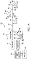
- FIG. 1A shows a wavelength multiplexed system 800 can use a compensated sensor array comprising multiple FBG sensors 821, 822, 823 disposed on a single optical fiber 811.
- the sensors 821 - 823 may be arranged to sense parameters including one or more of temperature, strain, and/or vibration, for example.
- input light is provided by the light source 810, which may comprise or be a light emitting diode (LED) or superluminescent laser diode (SLD), for example.
- LED light emitting diode
- SLD superluminescent laser diode
- the spectral characteristic (intensity vs. wavelength) of broadband light is shown by inset graph 891.
- the intensity is highest near the middle of the spectrum and falls off at the spectrum edges.
- the sensors 821, 822, 823 include compensation, e.g., one or more of different reflectivities and different attenuations, that decreases the difference in the intensity of the output signal light reflected by the sensors to compensate for the input light that is non-uniform in intensity, e.g., due to spectral non-uniformity of the light source and/or scattering losses in the optical fiber.
- the input light is transmitted via the fiber optic (FO) cable 811 to the first FBG sensor 821.
- the first FBG sensor 821 reflects a portion of the light in a first wavelength band having a central wavelength, ⁇ 1. Light having wavelengths other than within the first wavelength band is transmitted through the first FBG sensor 821 to the second FBG sensor 822.
- the spectral characteristic of the light transmitted to the second FBG sensor 822 is shown in inset graph 892 and exhibits a notch 881 at the first wavelength band centered at ⁇ 1 indicating that light in this wavelength band is reflected by the first sensor 821.
- the second FBG sensor 822 reflects a portion of the light in a second wavelength band having a central wavelength, ⁇ 2. Light that is not reflected by the second FBG sensor 822 is transmitted through the second FBG sensor 822 to the third FBG sensor 823.
- the spectral characteristic of the light transmitted to the third FBG sensor 823 is shown in inset graph 893 and includes notches 881, 882 centered at ⁇ 1 and ⁇ 2.
- the third FBG sensor 823 reflects a portion of the light in a third wavelength band having a central or peak wavelength, ⁇ 3. Light that is not reflected by the third FBG sensor 823 is transmitted through the third FBG sensor 823.
- the spectral characteristic of the light transmitted through the third FBG sensor 823 is shown in inset graph 894 and includes notches 881, 882, 883 centered at ⁇ 1, ⁇ 2, and ⁇ 3.
- Light in wavelength bands 861, 862, 863, having central wavelengths ⁇ 1, ⁇ 2 and ⁇ 3 is reflected by the first, second, or third FBG sensors 821, 822, 823, respectively, along the FO cables 811 and 811' to an the optical wavelength demultiplexer 850.
- Compensating input characteristics of sensors 821, 822, 823 cause the difference in the intensity peaks of the light 861, 862, 863 to be reduced when compared to the intensity peaks from an uncompensated sensor array.
- the sensor light 861, 862, 863 may be routed to a wavelength shift detector 855 that generates an electrical signal responsive to shifts in the central wavelengths ⁇ 1, ⁇ 2 and ⁇ 3 and/or wavelength bands of the sensor light.
- the wavelength shift detector 855 receives reflected light from each of the sensors and generates corresponding electrical signals in response to the shifts in the central wavelengths ⁇ 1, ⁇ 2 and ⁇ 3 or wavelength bands of the light reflected by the sensors 821 - 823.
- the analyzer 856 may compare the shifts to a characteristic base wavelength (a known wavelength) to determine whether changes in the values of the parameters sensed by the sensors 821 - 823 have occurred.
- the analyzer 856 may determine that the values of one or more of the sensed parameters have changed based on the wavelength shift analysis and may calculate a relative or absolute measurement of the change.
- the light source may scan through a wavelength range, emitting light in narrow wavelength bands to which the various sensors disposed on the FO cable are sensitive.
- the reflected light is sensed during a number of sensing periods that are timed relative to the emission of the narrowband light. For example, consider the scenario where sensors 1, 2, and 3 are disposed on a FO cable. Sensor 1 is sensitive to a wavelength band (WB1), sensor 2 is sensitive to wavelength band WB2, and sensor 3 is sensitive to WB3.
- the light source may be controlled to emit light having WB1 during time period 1 and sense reflected light during time period 1a that overlaps time period 1.
- the light source may emit light having WB2 during time period 2 and sense reflected light during time period 2a that overlaps time period 2.
- the light source may emit light having WB3 during time period 3 and sense reflected light during time period 3a that overlaps time period 3.
- each of the sensors may be interrogated during discrete time periods.
- a compensated sensor array as discussed herein may be useful to compensate for the intensity variation of the sources.
- FBGs may involve using a specific amount of pre-strain to work properly. Too little strain and the fiber 110 may not be in tension as shown in FIG. 1B , which may reduce sensitivity of the sensors 120. If too much strain is used as shown in FIG. 1C , reflectivity peaks may be outside the range of the read-out system (850, 855, 856).
- Embodiments herein describe systems for repeatably providing a specific pre-strain to work correctly during mounting of a potentially large number of FBG sensors.
- FIG. 1D shows an example of a correct amount of pre-strain. This mounting operation could be attaching fibers to an object, a structure, or a template.
- FIGS. 2A- 2D show an example system to apply a pre-strain to an optical fiber in accordance with embodiments described herein.
- a chassis 200 is shown having a base 210.
- a first wall 220 and a second wall 230 are arranged on the same plane and at opposite ends of the base 210. According to various embodiments, one or both of the first wall 220 and the second wall 230 are disposed substantially to extend substantially perpendicularly with respect to the base 210.
- One or both of the first wall and the second wall may include an attachment mechanism for detachably securing the optical fiber to the respective first and/or second wall.
- the attachment mechanism may include one or more of an adhesive mechanism, a magnetic mechanism, a vacuum mechanism, and a mechanical clamping mechanism.
- the second wall 230 is a fixed fiber attachment point.
- FIG. 2A shows an optical fiber 280 having a plurality of sensors 285.
- the optical fiber 280 is temporarily attached to the fixed fiber attachment point 230.
- a spring 290 is stretched to an extension that is within a specified force range between the first wall 220 and the second wall 230.
- the spring 290 is a flexure of the second wall 220.
- the spring 290 is connected to the fixed attachment point 230 and to a mobile fiber attachment point 295.
- the mobile attachment point is disposed between the first wall 220 and the second wall 230 and may be configured to move between the first wall 220 and the second wall 230.
- a low or substantially no friction mechanism 250 allows the mobile fiber attachment point 295 to move in a linear dimension with respect to the chassis 200 with low friction.
- FIG. 2C shows an optical fiber 280 attached to the mobile attachment point 295 with the optical fiber 280 in between the fixed attachment point 230 and the mobile attachment point 295.
- the mobile attachment point 295 is released as shown in FIG. 2D and the spring 290 exerts a restoring force that stretches the optical fiber 280 with a force substantially equal to the restoring force of the spring 290.
- the restoring force of the spring 290 may be proportional to the defection of the spring 290.
- the specific restoring force of the spring 290 is chosen based on the optical fiber type to provide the desired pre-strain in the optical fiber. According to various embodiments described herein, the restoring force is in a range of about 0.1 N to about 10 N. In some cases, the restoring force is about 1 N.
- One or both of the restoring force and the displacement of the second attachment point 295 is indicated by a dial, a display, and/or other type of indicator.
- the constant force is the value [e.g., in newtons] of the force provided by a constant force spring when it is extended within its constant force range.
- the constant force value depends the design of the spring.
- the constant force value depends on the material and/or the winding radius of the constant force spring.
- the specified force is the desired force to pre-strain the fiber by a desired amount.
- a CFS may be chosen that has a constant forced equal to the desired force.
- the force or extension need to be set precisely, using an indicator, for example For a CFS, so long as the extension is within the constant force range, it is known that the constant force is being substantially achieved. we are getting the constant force.
- FIG. 3 illustrates an example system that includes a bearing mechanism to provide the low or substantially no friction as the mobile attachment point is moved between the first wall and the second wall in accordance with embodiments described herein.
- the chassis 300 includes a base 310 and a first wall 360 and a second wall 320 that are arranged at opposite ends of the base 310.
- An optical fiber 350 having a plurality of sensors 355.
- the optical fiber 320 is temporarily attached to the first wall 360 that serves as a fixed fiber attachment point.
- a spring 330 is stretched to an extension that is within a specified force range between the first wall 360 and the second wall 320.
- the spring 330 is connected to the first wall 360 and to a mobile fiber attachment point 340.
- the mobile attachment point 340 is disposed between the first wall 360 and the second wall 320 and may be configured to move between the first wall 360 and the second wall 320.
- a bearing mechanism 390 allows the mobile fiber attachment point 340 to move in a linear dimension with respect to the chassis 300 with low friction.
- the spring is a constant force spring (CFS).
- CFS is a pre-tensioned metal strip where the restoring force tends to make the strip curl up.
- the restoring force of a CFS is substantially constant over a certain range of deflection.
- This type of spring is commonly used in tape measures and other retractable reels.
- the CFS provides a repeatable way to set the fiber pre-strain. Because the CFS applies the same force anywhere within its constant force range, the position of the attachment points is not critical. So long as the FBG is between the two fiber attachment points, the FBG will be under the same tension. This greatly relaxes the complexity of fiber handling during an install.
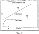
- FIG. 4 illustrates the load versus deflection for a constant force spring in accordance with embodiments described herein. As can be observed, as the helical extension 410 increases, the CFS provides a substantially constant force 420 after a deflection of IX.
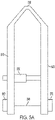
- FIGS. 5A and 5B show another example of a system to provide pre-strain to an optical fiber in accordance with embodiments described herein.
- FIG. 5A shows tweezers having fiber clamps 560, 570.
- the clamps 560 570 may be any type of removable clamp.
- the clamps may be one or more of an adhesive mechanism, a magnetic mechanism, a vacuum mechanism, and a mechanical clamping mechanism.
- a micrometer screw 530 is used to directly adjust the pre-strain of the optical fiber 540 that is stretched between a first side 510 and a second side 520.
- the first side 510 and the second side 520 are coupled via a pivot point 550.
- 5A and 5B may be configured to allow the optical fiber to be put in contact with an installation surface for subsequent bonding.
- a desired pre-strain is applied and after the fiber has been installed, the clamps 560, 570 can be released and the tool removed leaving the pre-strained fiber attached to the surface.
- a force or deflection sensor may be disposed between the micrometer screw 530 and the first side 510.
- the current pre-strain of the optical fiber 540 may be estimated based on the force sensed by the force sensor.
- Some embodiments may have an encoder to assist with setting the desired pre-strain. According to various embodiments, it may be difficult to get the desired pre-strain with the available screw.
- a reduction gear may make it easier for a user to get the desired pre-strain.
Landscapes
- Physics & Mathematics (AREA)
- General Physics & Mathematics (AREA)
- Optics & Photonics (AREA)
- Engineering & Computer Science (AREA)
- Civil Engineering (AREA)
- Structural Engineering (AREA)
- Optical Transform (AREA)
- Length Measuring Devices By Optical Means (AREA)
Abstract
Description
- This application relates generally to techniques for structural health monitoring. The application also relates to components, devices, systems, and methods pertaining to such techniques.
- Fiber optic (FO) sensors can be used for detecting parameters such as strain, temperature, pressure, current, voltage, chemical composition, and vibration. FO sensors are attractive components because they are thin, lightweight, sensitive, robust to harsh environments, and immune to electromagnetic interference (EMI) and electrostatic discharge. FO sensors can be arranged to simultaneously measure multiple parameters distributed in space with high sensitivity in multiplexed configurations over long optical fiber cables. One example of how this can be achieved is through fiber Bragg grating (FBG) sensors. A FBG sensor is formed by a periodic modulation of the refractive index along a finite length (typically a few mm) of the core of an optical fiber. This pattern reflects a wavelength, called the Bragg wavelength, determined by the periodicity of the refractive index modulation and the baseline index of refraction the fiber. The Bragg wavelength is sensitive to external stimulus (strain and/or temperature, etc.) that changes the periodicity of the grating and/or the index of refraction of the fiber. Thus, FBG sensors rely on the detection of small wavelength changes in response to stimuli of interest. In some implementations, FO sensors can be attached to structures and operated to detect parameters, e.g., strain, temperature, vibration, related to the health of the structures.
- Embodiments described herein involve an apparatus, comprising a chassis having a base. A first wall extends substantially perpendicularly from the base at a first edge of the base. The first wall is configured to be a first attachment point for an optical cable comprising one or more optical sensors. An opposing second wall extends substantially perpendicularly from the base at a second edge of the base. A mobile attachment point is configured to be a second attachment point for the optical cable. A spring is coupled to the second wall and the mobile attachment point. The spring is configured to provide a specified force as the mobile attachment point moves.
- Embodiments involve an apparatus, comprising a first side configured to be a first attachment point for an optical cable comprising one or more optical sensors. An opposing second side is configured to be a second attachment point for the optical cable. A pivot point is coupled to the first side and the second side. A first clamp is coupled to the first wall and is configured to attach the optical fiber to the first wall. A second clamp is coupled to the second wall and is configured to attach the optical fiber to the second wall. A screw extends between the first side and the second side. Tightening the screw increases a tension of the optical fiber.
- Throughout the specification reference is made to the appended drawings wherein:
-
FIG. 1A shows a wavelength multiplexed system can use a compensated sensor array comprising multiple FBG sensors disposed on a single optical fiber in accordance with embodiments described herein; -
FIG. 1B shows an optical fiber having too little pre-strain in accordance with embodiments described herein; -
FIG. 1C illustrates an optical fiber having to much pre-strain in accordance with embodiments described herein; -
FIG. 1D shows an optical fiber having a correct amount of pre-strain in accordance with embodiments described herein; -
FIGS. 2A- 2D show an example system to apply a pre-strain to an optical fiber in accordance with embodiments described herein; -
FIG. 3 illustrates an example system that includes a bearing mechanism to provide the low or substantially no friction as the mobile attachment point is moved between the first wall and the second wall in accordance with embodiments described herein; -
FIG. 4 illustrates the load versus deflection for a constant force spring in accordance with embodiments described herein; and -
FIGS. 5A and5B show another example of a system to provide pre-strain to an optical fiber comprising two sides and a pivot point in accordance with embodiments described herein. - The figures are not necessarily to scale. Like numbers used in the figures refer to like components. However, it will be understood that the use of a number to refer to a component in a given figure is not intended to limit the component in another figure labeled with the same number.
- Structural health monitoring is a large and growing field of study that aims to use sensors installed on assets, i.e., structures, to extract useful information about the health or condition of those structures. According to various embodiments described herein, these assets are built with the purpose of supporting loads. The assets can include any structure that can be loaded with objects. For example, the asset may include one or more of a road, a bridge, a runway, a port wharf, a cable structures, and a rail structure. While many embodiments described herein use the example of a bridge structure, it is to be understood that any of the methods and systems described herein can be applied to any type of structure that could benefit from structural health monitoring.
- Some embodiments disclosed herein involve apparatuses for attaching fiber optic (FO) sensors to structures. Fiber optic sensors can be deployed on various types of structures, e.g., bridges, roadways, railways, and electrical devices such as transformers, to monitor the structural health of the structures. The disclosed embodiments can facilitate mounting FO sensors to the structures in such a way that strain from the structures is transmitted to the sensors. The approaches discussed herein provide for attachment of FO sensors that is flexible enough to attach the FO sensors to a variety of different substrates, e.g. concrete, metal, and wood. Repeatability of the attachment is desired so that at least some or most of the FO sensors have the same pre-strain once attached. The disclosed attachment approaches can be simple and rapid to perform to facilitate the deployment of multiple FO sensors on a structure. Installing optical fibers on structures involves extensive fiber handling during the install. Optical fibers are fragile, and breaks and/or tangles cost time, which is detrimental e.g. because roads must be shut down to service a structure.
- Embodiments described herein are generally directed to installation of sensors on an asset that may be used to monitor the condition and/or health of the asset. The sensors may be optical sensors disposed on an optical fiber are optical sensors. For example, the sensors may be fiber Bragg grating (FBG) strain sensors, Fabry Perot sensors, and/or other interferometric optical sensors. In some cases, the sensors may include one or more of electrical and/or resistive sensors, mechanical sensors, and/or other types of strain gages. In some cases, a combination of different types of sensors may be used. Many embodiments described herein use FBG sensors as an example, but the techniques described may be applicable to other types of sensors as well.
- Fiber optic sensors can simultaneously measure multiple parameters distributed in space with high sensitivity in multiplexed configurations over long FO cables. One example of how this can be achieved is through fiber Bragg grating (FBG) sensors.
FIG. 1A shows a wavelength multiplexedsystem 800 can use a compensated sensor array comprisingmultiple FBG sensors optical fiber 811. The sensors 821 - 823 may be arranged to sense parameters including one or more of temperature, strain, and/or vibration, for example. As indicated inFIG. 1A , input light is provided by thelight source 810, which may comprise or be a light emitting diode (LED) or superluminescent laser diode (SLD), for example. The spectral characteristic (intensity vs. wavelength) of broadband light is shown byinset graph 891. The intensity is highest near the middle of the spectrum and falls off at the spectrum edges. Thesensors cable 811 to thefirst FBG sensor 821. Thefirst FBG sensor 821 reflects a portion of the light in a first wavelength band having a central wavelength, λ1. Light having wavelengths other than within the first wavelength band is transmitted through thefirst FBG sensor 821 to thesecond FBG sensor 822. The spectral characteristic of the light transmitted to thesecond FBG sensor 822 is shown ininset graph 892 and exhibits anotch 881 at the first wavelength band centered at λ1 indicating that light in this wavelength band is reflected by thefirst sensor 821. - The
second FBG sensor 822 reflects a portion of the light in a second wavelength band having a central wavelength, λ2. Light that is not reflected by thesecond FBG sensor 822 is transmitted through thesecond FBG sensor 822 to thethird FBG sensor 823. The spectral characteristic of the light transmitted to thethird FBG sensor 823 is shown ininset graph 893 and includesnotches - The
third FBG sensor 823 reflects a portion of the light in a third wavelength band having a central or peak wavelength, λ3. Light that is not reflected by thethird FBG sensor 823 is transmitted through thethird FBG sensor 823. The spectral characteristic of the light transmitted through thethird FBG sensor 823 is shown ininset graph 894 and includesnotches - Light in
wavelength bands third FBG sensors FO cables 811 and 811' to an theoptical wavelength demultiplexer 850. Compensating input characteristics ofsensors - From the
wavelength demultiplexer 850, thesensor light wavelength shift detector 855 that generates an electrical signal responsive to shifts in the central wavelengths λ1, λ2 and λ3 and/or wavelength bands of the sensor light. Thewavelength shift detector 855 receives reflected light from each of the sensors and generates corresponding electrical signals in response to the shifts in the central wavelengths λ1, λ2 and λ3 or wavelength bands of the light reflected by the sensors 821 - 823. Theanalyzer 856 may compare the shifts to a characteristic base wavelength (a known wavelength) to determine whether changes in the values of the parameters sensed by the sensors 821 - 823 have occurred. Theanalyzer 856 may determine that the values of one or more of the sensed parameters have changed based on the wavelength shift analysis and may calculate a relative or absolute measurement of the change. - In some cases, instead of emitting broadband light, the light source may scan through a wavelength range, emitting light in narrow wavelength bands to which the various sensors disposed on the FO cable are sensitive. The reflected light is sensed during a number of sensing periods that are timed relative to the emission of the narrowband light. For example, consider the scenario where sensors 1, 2, and 3 are disposed on a FO cable. Sensor 1 is sensitive to a wavelength band (WB1), sensor 2 is sensitive to wavelength band WB2, and sensor 3 is sensitive to WB3. The light source may be controlled to emit light having WB1 during time period 1 and sense reflected light during time period 1a that overlaps time period 1. Following time period 1a, the light source may emit light having WB2 during time period 2 and sense reflected light during time period 2a that overlaps time period 2. Following time period 2a, the light source may emit light having WB3 during time period 3 and sense reflected light during time period 3a that overlaps time period 3. Using this version of time domain multiplexing, each of the sensors may be interrogated during discrete time periods. When the intensity of the narrowband light sources varies, a compensated sensor array as discussed herein may be useful to compensate for the intensity variation of the sources.
- FBGs may involve using a specific amount of pre-strain to work properly. Too little strain and the
fiber 110 may not be in tension as shown inFIG. 1B , which may reduce sensitivity of thesensors 120. If too much strain is used as shown inFIG. 1C , reflectivity peaks may be outside the range of the read-out system (850, 855, 856). Embodiments herein describe systems for repeatably providing a specific pre-strain to work correctly during mounting of a potentially large number of FBG sensors.FIG. 1D shows an example of a correct amount of pre-strain. This mounting operation could be attaching fibers to an object, a structure, or a template. -
FIGS. 2A- 2D show an example system to apply a pre-strain to an optical fiber in accordance with embodiments described herein. Achassis 200 is shown having abase 210. Afirst wall 220 and asecond wall 230 are arranged on the same plane and at opposite ends of thebase 210. According to various embodiments, one or both of thefirst wall 220 and thesecond wall 230 are disposed substantially to extend substantially perpendicularly with respect to thebase 210. One or both of the first wall and the second wall may include an attachment mechanism for detachably securing the optical fiber to the respective first and/or second wall. The attachment mechanism may include one or more of an adhesive mechanism, a magnetic mechanism, a vacuum mechanism, and a mechanical clamping mechanism. - According to various embodiments described herein, the
second wall 230 is a fixed fiber attachment point.FIG. 2A shows anoptical fiber 280 having a plurality ofsensors 285. Theoptical fiber 280 is temporarily attached to the fixedfiber attachment point 230. InFIG. 2B , aspring 290 is stretched to an extension that is within a specified force range between thefirst wall 220 and thesecond wall 230. In some cases, thespring 290 is a flexure of thesecond wall 220. Thespring 290 is connected to the fixedattachment point 230 and to a mobile fiber attachment point 295. The mobile attachment point is disposed between thefirst wall 220 and thesecond wall 230 and may be configured to move between thefirst wall 220 and thesecond wall 230. A low or substantially nofriction mechanism 250 allows the mobile fiber attachment point 295 to move in a linear dimension with respect to thechassis 200 with low friction. -
FIG. 2C shows anoptical fiber 280 attached to the mobile attachment point 295 with theoptical fiber 280 in between the fixedattachment point 230 and the mobile attachment point 295. Finally, the mobile attachment point 295 is released as shown inFIG. 2D and thespring 290 exerts a restoring force that stretches theoptical fiber 280 with a force substantially equal to the restoring force of thespring 290. The restoring force of thespring 290 may be proportional to the defection of thespring 290. The specific restoring force of thespring 290 is chosen based on the optical fiber type to provide the desired pre-strain in the optical fiber. According to various embodiments described herein, the restoring force is in a range of about 0.1 N to about 10 N. In some cases, the restoring force is about 1 N. One or both of the restoring force and the displacement of the second attachment point 295 is indicated by a dial, a display, and/or other type of indicator. - The constant force is the value [e.g., in newtons] of the force provided by a constant force spring when it is extended within its constant force range. The constant force value depends the design of the spring. For example, the constant force value depends on the material and/or the winding radius of the constant force spring. The specified force is the desired force to pre-strain the fiber by a desired amount. For a pre-strain tool using a CFS, a CFS may be chosen that has a constant forced equal to the desired force.
- For a pre-strain tool using a Hooke's law spring, the force or extension need to be set precisely, using an indicator, for example For a CFS, so long as the extension is within the constant force range, it is known that the constant force is being substantially achieved. we are getting the constant force.
-
FIG. 3 illustrates an example system that includes a bearing mechanism to provide the low or substantially no friction as the mobile attachment point is moved between the first wall and the second wall in accordance with embodiments described herein. In this example, thechassis 300 includes abase 310 and afirst wall 360 and asecond wall 320 that are arranged at opposite ends of thebase 310. Anoptical fiber 350 having a plurality ofsensors 355. Theoptical fiber 320 is temporarily attached to thefirst wall 360 that serves as a fixed fiber attachment point. Aspring 330 is stretched to an extension that is within a specified force range between thefirst wall 360 and thesecond wall 320. Thespring 330 is connected to thefirst wall 360 and to a mobilefiber attachment point 340. Themobile attachment point 340 is disposed between thefirst wall 360 and thesecond wall 320 and may be configured to move between thefirst wall 360 and thesecond wall 320. Abearing mechanism 390 allows the mobilefiber attachment point 340 to move in a linear dimension with respect to thechassis 300 with low friction. - According to various embodiments, the spring is a constant force spring (CFS). A CFS is a pre-tensioned metal strip where the restoring force tends to make the strip curl up. The restoring force of a CFS is substantially constant over a certain range of deflection. This type of spring is commonly used in tape measures and other retractable reels. The CFS provides a repeatable way to set the fiber pre-strain. Because the CFS applies the same force anywhere within its constant force range, the position of the attachment points is not critical. So long as the FBG is between the two fiber attachment points, the FBG will be under the same tension. This greatly relaxes the complexity of fiber handling during an install.
FIG. 4 illustrates the load versus deflection for a constant force spring in accordance with embodiments described herein. As can be observed, as thehelical extension 410 increases, the CFS provides a substantiallyconstant force 420 after a deflection of IX. -
FIGS. 5A and5B show another example of a system to provide pre-strain to an optical fiber in accordance with embodiments described herein.FIG. 5A shows tweezers having fiber clamps 560, 570. Theclamps 560 570 may be any type of removable clamp. For example, the clamps may be one or more of an adhesive mechanism, a magnetic mechanism, a vacuum mechanism, and a mechanical clamping mechanism. Amicrometer screw 530 is used to directly adjust the pre-strain of theoptical fiber 540 that is stretched between afirst side 510 and asecond side 520. Thefirst side 510 and thesecond side 520 are coupled via apivot point 550. The tool ofFIGS. 5A and5B may be configured to allow the optical fiber to be put in contact with an installation surface for subsequent bonding. A desired pre-strain is applied and after the fiber has been installed, theclamps micrometer screw 530 and thefirst side 510. The current pre-strain of theoptical fiber 540 may be estimated based on the force sensed by the force sensor. Some embodiments may have an encoder to assist with setting the desired pre-strain. According to various embodiments, it may be difficult to get the desired pre-strain with the available screw. A reduction gear may make it easier for a user to get the desired pre-strain. - Unless otherwise indicated, all numbers expressing feature sizes, amounts, and physical properties used in the specification and claims are to be understood as being modified in all instances by the term "about." Accordingly, unless indicated to the contrary, the numerical parameters set forth in the foregoing specification and attached claims are approximations that can vary depending upon the desired properties sought to be obtained by those skilled in the art utilizing the teachings disclosed herein. The use of numerical ranges by endpoints includes all numbers within that range (e.g. 1 to 5 includes 1, 1.5, 2, 2.75, 3, 3.80, 4, and 5) and any range within that range.
- The various embodiments described above may be implemented using circuitry and/or software modules that interact to provide particular results. One of skill in the computing arts can readily implement such described functionality, either at a modular level or as a whole, using knowledge generally known in the art. For example, the flowcharts illustrated herein may be used to create computer-readable instructions/code for execution by a processor. Such instructions may be stored on a computer-readable medium and transferred to the processor for execution as is known in the art.
- The foregoing description of the example embodiments have been presented for the purposes of illustration and description. It is not intended to be exhaustive or to limit the inventive concepts to the precise form disclosed. Many modifications and variations are possible in light of the above teachings. Any or all features of the disclosed embodiments can be applied individually or in any combination, not meant to be limiting but purely illustrative. It is intended that the scope be limited by the claims appended herein and not with the detailed description.
Claims (15)
- An apparatus, comprising:
a chassis comprising:a base;a first wall extending substantially perpendicularly from the base at a first edge of the base, the first wall configured to be a first attachment point for an optical cable comprising one or more optical sensors;an opposing second wall extending substantially perpendicularly from the base at a second edge of the base;a mobile attachment point configured to be a second attachment point for the optical cable; anda spring coupled to the second wall and the mobile attachment point, the spring configured to provide a specified force as the mobile attachment point moves. - The apparatus of claim 1, wherein the one or more optical sensors comprise one or more fiber Bragg grating (FBG) sensors.
- The apparatus of claim 1, wherein the spring is a constant force spring that is configured to provide a constant force as the mobile attachment point moves between the first wall and the second wall, optionally wherein the constant force spring is configured to be stretched to a stretched extension that is within a constant force range.
- The apparatus of claim 3, wherein the constant force spring is configured to exert a restoring force that stretches the optical cable with a force substantially equal to the restoring force of the constant force spring when the mobile attachment point is released from the stretched extension.
- The apparatus of claim 4, wherein the restoring force may be chosen based on a type of optical cable to provide a desired pre-strain.
- The apparatus of claim 4, wherein the restoring force is in a range of about 0.1 N to about 10 N, optionally wherein the restoring force is about 1 N.
- The apparatus of claim 1, further comprising a bearing mechanism disposed on the base and configured to allow the mobile attachment point to move along the base.
- The apparatus of claim 1, wherein the first and second attachment points are reversible.
- The apparatus of claim 1, wherein at least one of the first point and the second attachment point comprises one or more of a magnetic attachment, clamp, adhesive, and a vacuum.
- The apparatus of claim 1, wherein the spring exerts a restoring force proportional to its deflection.
- The apparatus of claim 10, wherein the spring is a flexure of the second wall.
- The apparatus of claim 10, wherein the restoring force is indicated by a dial, display, or other indicator or wherein a displacement of the second attachment point is indicated by a dial, display, or other indicator.
- The apparatus of claim 10, wherein the restoring force is in a range of 0.1-10 N.
- The apparatus of claim 1, wherein the mobile attachment point is disposed between the first wall and the second wall and is configured to move between the first wall and the second wall; or wherein the mobile attachment point is disposed on the second wall.
- An apparatus, comprising:a first side configured to be a first attachment point for an optical cable comprising one or more optical sensors;an opposing second side configured to be a second attachment point for the optical cable;a pivot point coupled to the first side and the second side;a first clamp coupled to the first wall configured to attach the optical fiber to the first wall;a second clamp coupled to the second wall configured to attach the optical fiber to the second wall; anda screw extending between the first side and the second side, wherein tightening the screw increases a tension of the optical fiber;optionally further comprising a force sensor disposed between the screw and one or both of the first side and the second side.
Applications Claiming Priority (1)
| Application Number | Priority Date | Filing Date | Title |
|---|---|---|---|
| US17/235,101 US11668889B2 (en) | 2021-04-20 | 2021-04-20 | System for applying pre-strain to an optical sensor |
Publications (1)
| Publication Number | Publication Date |
|---|---|
| EP4080171A1 true EP4080171A1 (en) | 2022-10-26 |
Family
ID=81074150
Family Applications (1)
| Application Number | Title | Priority Date | Filing Date |
|---|---|---|---|
| EP22165830.5A Ceased EP4080171A1 (en) | 2021-04-20 | 2022-03-31 | System for applying pre-strain to an optical sensor |
Country Status (3)
| Country | Link |
|---|---|
| US (2) | US11668889B2 (en) |
| EP (1) | EP4080171A1 (en) |
| AU (1) | AU2022201808A1 (en) |
Families Citing this family (1)
| Publication number | Priority date | Publication date | Assignee | Title |
|---|---|---|---|---|
| US12704390B2 (en) * | 2022-12-09 | 2026-08-11 | Palo Alto Research Center Incorporated | Optical fiber sensing based on changes in laser emission wavelength |
Citations (2)
| Publication number | Priority date | Publication date | Assignee | Title |
|---|---|---|---|---|
| EP1816432A1 (en) * | 2006-02-06 | 2007-08-08 | Micron Optics, Inc. | Fiber optic strain gage |
| EP2247971B1 (en) * | 2008-02-26 | 2011-10-05 | FBGS International BVBA | Method and means for mounting a fibre Bragg grating on a surface |
Family Cites Families (46)
| Publication number | Priority date | Publication date | Assignee | Title |
|---|---|---|---|---|
| US2892013A (en) | 1955-05-25 | 1959-06-23 | Douglas Aircraft Co Inc | Bulkhead seal for wire bundles |
| JPS6319780A (en) | 1986-07-10 | 1988-01-27 | 矢崎総業株式会社 | Formation of covered layer at connection of wire |
| US5011252A (en) | 1986-11-14 | 1991-04-30 | The Commonwealth Of Australia | Fabrication of fibre optic components |
| FR2630419B1 (en) | 1988-04-20 | 1990-08-17 | Telecommunications Sa | REEL AND ROLLER-unwIND APPARATUS FOR FIBER OPTIC CABLE |
| AUPM547194A0 (en) * | 1994-05-06 | 1994-06-02 | University Of Sydney, The | Variable property light transmitting device |
| JP3301253B2 (en) | 1995-02-24 | 2002-07-15 | 日本電信電話株式会社 | Optical connector automatic assembly and inspection system |
| US5844667A (en) * | 1997-01-28 | 1998-12-01 | Cidra Corporation | Fiber optic pressure sensor with passive temperature compensation |
| JP3571936B2 (en) | 1997-11-11 | 2004-09-29 | 古河電気工業株式会社 | Pressure measuring device |
| US6101301A (en) * | 1998-04-17 | 2000-08-08 | Lucent Technologies Inc. | Temperature-compensated optical fiber gratings with fine wavelength tuning |
| FR2781714B1 (en) | 1998-07-29 | 2000-09-22 | Europ De Fabrications Ind Sefi | METHOD FOR MANUFACTURING A REMOTE CONTROL DEVICE INCLUDING A MOBILE CONTROL CABLE IN A SHEATH |
| US6449402B1 (en) * | 1999-11-19 | 2002-09-10 | Finisar Corporation | Method and apparatus for compensating an optical filter |
| DE10004384C2 (en) | 2000-02-02 | 2003-04-03 | Daimler Chrysler Ag | Arrangement and method for detecting strains and temperatures and their changes on a carrier, in particular one consisting of metal, plastic or ceramic carrier, applied topcoat |
| US6668105B2 (en) | 2000-07-27 | 2003-12-23 | Systems Planning & Analysis, Inc. | Fiber optic strain sensor |
| US6374015B1 (en) * | 2000-08-01 | 2002-04-16 | Rich Key Technologies Limited | Temperature-compensating device with tunable mechanism for optical fiber gratings |
| US6907164B2 (en) * | 2001-02-22 | 2005-06-14 | Teraxion, Inc. | Adjustable athermal package for optical fiber devices |
| JP4065749B2 (en) * | 2001-10-23 | 2008-03-26 | 株式会社フジクラ | Optical fiber cutting machine and optical fiber cutting method using the same |
| US6636667B2 (en) * | 2001-12-06 | 2003-10-21 | Oplink Communications Inc. | Tunable optical fiber grating package with low temperature dependency |
| TW545365U (en) | 2001-12-13 | 2003-08-01 | Ind Tech Res Inst | Handheld optical fiber cutting apparatus |
| US7400812B2 (en) | 2003-09-25 | 2008-07-15 | Nufern | Apparatus and methods for accommodating loops of optical fiber |
| JP4351937B2 (en) | 2004-03-17 | 2009-10-28 | 成田国際空港株式会社 | Road surface freezing detection sensor, road surface freezing detection sensor installation method and road surface freezing detection method |
| US7134219B2 (en) | 2004-05-21 | 2006-11-14 | The Regents Of The University Of California | Fiber optic gap gauge |
| BRPI0404129A (en) * | 2004-05-31 | 2006-01-17 | Petroleo Brasileiro Sa | Fiber optic ph sensor |
| US7315681B2 (en) | 2004-08-09 | 2008-01-01 | Anthony Kewitsch | Fiber optic rotary coupling and devices |
| US7856888B2 (en) | 2007-11-15 | 2010-12-28 | Micron Optics Inc. | Fiber optic strain gage and carrier |
| US20090162595A1 (en) | 2007-12-19 | 2009-06-25 | Chan Ko | Striped adhesive construction and method and die for making same |
| US8474742B2 (en) | 2009-07-30 | 2013-07-02 | Adc Telecommunications, Inc. | Spool for telecommunications cable and method |
| US9908742B2 (en) | 2012-04-30 | 2018-03-06 | Commscope Technologies Llc | Cable storage spool with center feed |
| CN102636838B (en) * | 2012-05-16 | 2013-09-11 | 杭州联光电子有限公司 | Package method and device for fiber bragg grating with adjustable central wavelength and adjustable temperature coefficient |
| CN104033457B (en) | 2013-03-06 | 2016-06-22 | 中国飞机强度研究所 | A kind of fiber Bragg grating sensor method of attaching |
| NL1040338C2 (en) * | 2013-08-16 | 2015-02-19 | Beethoven Marine Systems B V | Sensor for detecting pressure waves in a liquid. |
| NL1040505C2 (en) * | 2013-11-19 | 2015-05-26 | Beethoven Marine Systems B V | Sensor for detecting pressure waves in a fluid, provided with static pressure compensation. |
| CN104596437B (en) * | 2015-01-12 | 2018-01-12 | 武汉理工大学 | Hand-held paste tool and method for fiber grating surface strain measurement |
| EP3295185B1 (en) * | 2015-05-08 | 2019-07-10 | Fugro Technology B.V. | Optical sensor device, sensor apparatus, cable and method of manufacturing |
| US10495835B2 (en) | 2015-09-28 | 2019-12-03 | Commscope Technologies Llc | Fiber optic cable spool |
| CN105651319A (en) * | 2016-01-05 | 2016-06-08 | 武汉理工大学 | Packaging device for applying constant pre-stress on fiber grating sensor |
| JP6623490B2 (en) | 2016-02-12 | 2019-12-25 | Seiオプティフロンティア株式会社 | Optical fiber cutting equipment |
| CN206019592U (en) * | 2016-08-24 | 2017-03-15 | 成都阜特科技股份有限公司 | A kind of fiber-optic grating sensor pretensioning tool |
| EP3312556A1 (en) | 2016-10-23 | 2018-04-25 | Vrije Universiteit Brussel | Mechanical strain amplifying transducer |
| CN206486463U (en) | 2016-12-22 | 2017-09-12 | 3M创新有限公司 | Adhesive tape |
| JP6542834B2 (en) * | 2017-05-15 | 2019-07-10 | 株式会社フジクラ | Fiber cutter |
| US10295749B1 (en) | 2018-02-15 | 2019-05-21 | International Business Machines Corporation | Optical interconnect attach to photonic device with partitioning adhesive function |
| CN108508561A (en) | 2018-06-05 | 2018-09-07 | 华域视觉科技(上海)有限公司 | Optical fibre installation apparatus and car light assembly system |
| US10816747B2 (en) | 2019-03-11 | 2020-10-27 | Ofs Fitel, Llc | Installation of small form factor fibers at user premises |
| CN112217144A (en) | 2019-07-09 | 2021-01-12 | 武汉光卓科技有限公司 | Tensioning device for long-distance erection of optical fiber cables |
| JP7488273B2 (en) | 2019-09-17 | 2024-05-21 | 日東電工株式会社 | Sensor package and method for installing the sensor package |
| CN111812785B (en) | 2020-04-21 | 2022-12-09 | 贵州电网有限责任公司 | Fixing frame for standby tail fibers |
-
2021
- 2021-04-20 US US17/235,101 patent/US11668889B2/en active Active
-
2022
- 2022-03-16 AU AU2022201808A patent/AU2022201808A1/en active Pending
- 2022-03-31 EP EP22165830.5A patent/EP4080171A1/en not_active Ceased
-
2023
- 2023-04-25 US US18/138,929 patent/US12449282B2/en active Active
Patent Citations (2)
| Publication number | Priority date | Publication date | Assignee | Title |
|---|---|---|---|---|
| EP1816432A1 (en) * | 2006-02-06 | 2007-08-08 | Micron Optics, Inc. | Fiber optic strain gage |
| EP2247971B1 (en) * | 2008-02-26 | 2011-10-05 | FBGS International BVBA | Method and means for mounting a fibre Bragg grating on a surface |
Also Published As
| Publication number | Publication date |
|---|---|
| US20220334335A1 (en) | 2022-10-20 |
| US11668889B2 (en) | 2023-06-06 |
| US20230266554A1 (en) | 2023-08-24 |
| AU2022201808A1 (en) | 2022-11-03 |
| US12449282B2 (en) | 2025-10-21 |
Similar Documents
| Publication | Publication Date | Title |
|---|---|---|
| Todd et al. | A novel Bragg grating sensor interrogation system utilizing a scanning filter, a Mach-Zehnder interferometer and a 3× 3 coupler | |
| JP3519333B2 (en) | Optical fiber sensor | |
| US6396572B1 (en) | Apparatus for comparing tensile or compressive stresses imposed on different parts of optical fiber | |
| EP2989428B1 (en) | Fiber-grating sensors having longitudinal-strain-inducing jackets and sensor systems and structures including such sensors | |
| US7856888B2 (en) | Fiber optic strain gage and carrier | |
| JP7706379B2 (en) | Method and system for determining brake torque by detection performed by a photonic sensor at a fixed interface between a brake caliper body and the respective support | |
| US20020041722A1 (en) | Optical sensing device containing fiber bragg gratings | |
| CA2584376C (en) | Embeddable polarimetric fiber optic sensor and method for monitoring of structures | |
| Zhu et al. | Temperature-insensitive fiber Bragg grating accelerometer | |
| WO2008028138A2 (en) | Method and apparatus for high frequency optical sensor interrogation | |
| US12449282B2 (en) | System for applying pre-strain to an optical sensor | |
| US7050662B2 (en) | Fiber Bragg grating compression sensor system | |
| US6744035B2 (en) | Passive, temperature compensated techniques for tunable filter calibration in bragg-grating interrogation systems | |
| RU163305U1 (en) | FIBER OPTICAL DEFORMATION SENSOR (LONGITUDINAL TENSION / COMPRESSION) | |
| Zhang et al. | Experimental investigation on optical spectral deformation of embedded FBG sensors | |
| EP4080170B1 (en) | Smart cassette for installing optical fiber | |
| Sirkis | Optical fiber strain sensing in engineering mechanics | |
| US11619794B2 (en) | System for installing optical fiber | |
| Enciu et al. | Strain measurements using fiber Bragg grating sensors in structural health monitoring | |
| WO2025034652A2 (en) | Sensing device | |
| Ohn et al. | Phase-based Bragg intra-grating sensing of strain gradients | |
| Ou | Fiber Bragg Gratings Strain Sensors for Railway Applications | |
| Habel et al. | KALFOS-a validation facility for strain transfer characterization of surface-applied strain sensors | |
| Kersey et al. | Fiber Bragg grating based sensors with nonlinear strain transduction | |
| Mrad | Aircraft fiber optic structural health monitoring |
Legal Events
| Date | Code | Title | Description |
|---|---|---|---|
| PUAI | Public reference made under article 153(3) epc to a published international application that has entered the european phase |
Free format text: ORIGINAL CODE: 0009012 |
|
| STAA | Information on the status of an ep patent application or granted ep patent |
Free format text: STATUS: THE APPLICATION HAS BEEN PUBLISHED |
|
| AK | Designated contracting states |
Kind code of ref document: A1 Designated state(s): AL AT BE BG CH CY CZ DE DK EE ES FI FR GB GR HR HU IE IS IT LI LT LU LV MC MK MT NL NO PL PT RO RS SE SI SK SM TR |
|
| STAA | Information on the status of an ep patent application or granted ep patent |
Free format text: STATUS: REQUEST FOR EXAMINATION WAS MADE |
|
| 17P | Request for examination filed |
Effective date: 20230426 |
|
| RBV | Designated contracting states (corrected) |
Designated state(s): AL AT BE BG CH CY CZ DE DK EE ES FI FR GB GR HR HU IE IS IT LI LT LU LV MC MK MT NL NO PL PT RO RS SE SI SK SM TR |
|
| STAA | Information on the status of an ep patent application or granted ep patent |
Free format text: STATUS: EXAMINATION IS IN PROGRESS |
|
| 17Q | First examination report despatched |
Effective date: 20231011 |
|
| STAA | Information on the status of an ep patent application or granted ep patent |
Free format text: STATUS: THE APPLICATION HAS BEEN REFUSED |
|
| 18R | Application refused |
Effective date: 20250801 |