EP4080067B1 - Connector with gate - Google Patents
Connector with gate Download PDFInfo
- Publication number
- EP4080067B1 EP4080067B1 EP21200755.3A EP21200755A EP4080067B1 EP 4080067 B1 EP4080067 B1 EP 4080067B1 EP 21200755 A EP21200755 A EP 21200755A EP 4080067 B1 EP4080067 B1 EP 4080067B1
- Authority
- EP
- European Patent Office
- Prior art keywords
- connector
- screwgate
- tag
- ring
- finger
- Prior art date
- Legal status (The legal status is an assumption and is not a legal conclusion. Google has not performed a legal analysis and makes no representation as to the accuracy of the status listed.)
- Active
Links
Images

Classifications
-
- F—MECHANICAL ENGINEERING; LIGHTING; HEATING; WEAPONS; BLASTING
- F16—ENGINEERING ELEMENTS AND UNITS; GENERAL MEASURES FOR PRODUCING AND MAINTAINING EFFECTIVE FUNCTIONING OF MACHINES OR INSTALLATIONS; THERMAL INSULATION IN GENERAL
- F16B—DEVICES FOR FASTENING OR SECURING CONSTRUCTIONAL ELEMENTS OR MACHINE PARTS TOGETHER, e.g. NAILS, BOLTS, CIRCLIPS, CLAMPS, CLIPS OR WEDGES; JOINTS OR JOINTING
- F16B45/00—Hooks; Eyes
- F16B45/02—Hooks with pivoting or elastically bending closing member
- F16B45/023—Hooks with pivoting or elastically bending closing member the closing member pivoting about an axis perpendicular to the plane of the hook
-
- H—ELECTRICITY
- H05—ELECTRIC TECHNIQUES NOT OTHERWISE PROVIDED FOR
- H05K—PRINTED CIRCUITS; CASINGS OR CONSTRUCTIONAL DETAILS OF ELECTRIC APPARATUS; MANUFACTURE OF ASSEMBLAGES OF ELECTRICAL COMPONENTS
- H05K5/00—Casings, cabinets or drawers for electric apparatus
- H05K5/02—Details
- H05K5/0217—Mechanical details of casings
- H05K5/0221—Locks; Latches
-
- F—MECHANICAL ENGINEERING; LIGHTING; HEATING; WEAPONS; BLASTING
- F16—ENGINEERING ELEMENTS AND UNITS; GENERAL MEASURES FOR PRODUCING AND MAINTAINING EFFECTIVE FUNCTIONING OF MACHINES OR INSTALLATIONS; THERMAL INSULATION IN GENERAL
- F16B—DEVICES FOR FASTENING OR SECURING CONSTRUCTIONAL ELEMENTS OR MACHINE PARTS TOGETHER, e.g. NAILS, BOLTS, CIRCLIPS, CLAMPS, CLIPS OR WEDGES; JOINTS OR JOINTING
- F16B45/00—Hooks; Eyes
- F16B45/02—Hooks with pivoting or elastically bending closing member
- F16B45/027—Hooks with pivoting or elastically bending closing member and having position-locking means for the closing member
-
- G—PHYSICS
- G06—COMPUTING OR CALCULATING; COUNTING
- G06K—GRAPHICAL DATA READING; PRESENTATION OF DATA; RECORD CARRIERS; HANDLING RECORD CARRIERS
- G06K19/00—Record carriers for use with machines and with at least a part designed to carry digital markings
- G06K19/06—Record carriers for use with machines and with at least a part designed to carry digital markings characterised by the kind of the digital marking, e.g. shape, nature, code
- G06K19/067—Record carriers with conductive marks, printed circuits or semiconductor circuit elements, e.g. credit or identity cards also with resonating or responding marks without active components
- G06K19/07—Record carriers with conductive marks, printed circuits or semiconductor circuit elements, e.g. credit or identity cards also with resonating or responding marks without active components with integrated circuit chips
- G06K19/077—Constructional details, e.g. mounting of circuits in the carrier
- G06K19/07749—Constructional details, e.g. mounting of circuits in the carrier the record carrier being capable of non-contact communication, e.g. constructional details of the antenna of a non-contact smart card
- G06K19/07758—Constructional details, e.g. mounting of circuits in the carrier the record carrier being capable of non-contact communication, e.g. constructional details of the antenna of a non-contact smart card arrangements for adhering the record carrier to further objects or living beings, functioning as an identification tag
-
- F—MECHANICAL ENGINEERING; LIGHTING; HEATING; WEAPONS; BLASTING
- F16—ENGINEERING ELEMENTS AND UNITS; GENERAL MEASURES FOR PRODUCING AND MAINTAINING EFFECTIVE FUNCTIONING OF MACHINES OR INSTALLATIONS; THERMAL INSULATION IN GENERAL
- F16B—DEVICES FOR FASTENING OR SECURING CONSTRUCTIONAL ELEMENTS OR MACHINE PARTS TOGETHER, e.g. NAILS, BOLTS, CIRCLIPS, CLAMPS, CLIPS OR WEDGES; JOINTS OR JOINTING
- F16B2200/00—Constructional details of connections not covered for in other groups of this subclass
- F16B2200/95—Constructional details of connections not covered for in other groups of this subclass with markings, colours, indicators or the like
-
- F—MECHANICAL ENGINEERING; LIGHTING; HEATING; WEAPONS; BLASTING
- F16—ENGINEERING ELEMENTS AND UNITS; GENERAL MEASURES FOR PRODUCING AND MAINTAINING EFFECTIVE FUNCTIONING OF MACHINES OR INSTALLATIONS; THERMAL INSULATION IN GENERAL
- F16B—DEVICES FOR FASTENING OR SECURING CONSTRUCTIONAL ELEMENTS OR MACHINE PARTS TOGETHER, e.g. NAILS, BOLTS, CIRCLIPS, CLAMPS, CLIPS OR WEDGES; JOINTS OR JOINTING
- F16B45/00—Hooks; Eyes
- F16B45/02—Hooks with pivoting or elastically bending closing member
- F16B45/024—Hooks with pivoting or elastically bending closing member and having means biasing the closing member about the pivot
- F16B45/026—Hooks with pivoting or elastically bending closing member and having means biasing the closing member about the pivot and including a coil type spring
-
- F—MECHANICAL ENGINEERING; LIGHTING; HEATING; WEAPONS; BLASTING
- F16—ENGINEERING ELEMENTS AND UNITS; GENERAL MEASURES FOR PRODUCING AND MAINTAINING EFFECTIVE FUNCTIONING OF MACHINES OR INSTALLATIONS; THERMAL INSULATION IN GENERAL
- F16B—DEVICES FOR FASTENING OR SECURING CONSTRUCTIONAL ELEMENTS OR MACHINE PARTS TOGETHER, e.g. NAILS, BOLTS, CIRCLIPS, CLAMPS, CLIPS OR WEDGES; JOINTS OR JOINTING
- F16B45/00—Hooks; Eyes
- F16B45/02—Hooks with pivoting or elastically bending closing member
- F16B45/027—Hooks with pivoting or elastically bending closing member and having position-locking means for the closing member
- F16B45/028—Hooks with pivoting or elastically bending closing member and having position-locking means for the closing member the position-locking means being pivotally connected
Definitions
- the present invention relates to a connector of the type intended for the assembly of fall prevention and/or protection systems for works at height for persons, such as on construction sites, in maintenance operations at height, in technical rescue, and for the assembly of fall prevention and/or protection systems in mountaineering including climbing, in leisure time, such as in amusement parks with elevated paths.
- the connector is substantially a special metal hook or ring of varying shape and size, fitted with a spring element that ensures the closure of the hook itself, which, when closed, takes on the characteristics of a ring.
- the invention applies to all of these variants, but of particular interest here are connectors having an opening locking mechanism (commonly known as a "screwgate”), the latter being a bushing that can be arranged in a non-operational position in which it allows the connector to be opened by moving its elastically oscillating lever, and in a position in which it locks the lever while keeping the connector closed (usually the normal position and used to support forces).
- a screwgate opening locking mechanism
- the screwgate can be manually operated (e.g. by screw) or automatically operated by a spring (e.g. two- or three-movement snap closure); this system serves, once closed, to prevent an accidental opening of the connector lever. This is advantageous for the normal manoeuvres envisaged by the techniques of use, such as self-belaying during a stop and when manoeuvring a person up a wall or in any case in an exposed condition.
- a spring e.g. two- or three-movement snap closure
- the connectors are subject to precise technical standards regarding their mechanical properties, such as mechanical strengths, shapes and surface state, the information to be affixed, the requirements of the mechanisms.
- the climbing and mountaineering connectors are considered as personal protective equipment and are certified according to the relevant standards; in Europe the standards are harmonised with the European regulations and directives in force (e.g. EN 362 and EN 12275), while in the rest of the world the requirements vary locally and according to technical standards of the sector (e.g. ANSI/ASSP Z359 and CSA Z259 Fall Protection Code, NFPA 1983).
- the climbing and mountaineering connectors can also bear the international mark UIAA, the documentation for which is in the public domain: the latter provides for more restrictive constraints on manufacturers aimed at ensuring additional safety thanks to continuously updated information from users, associations, manufacturers, and laboratories all over the world, and not restricted to the European context.
- the minimum required breaking loads vary according to the intended use of the connector: along the longitudinal axis (i.e. in the same direction as the long side of the connector) with closed lever it can vary between 20 and 25 kN , while the longitudinal one with open lever between 5 and 7 kN, and the one in the transverse direction between 7 and 10 kN.
- the connectors with different breaking loads depending on the needs.
- connectors are generally stamped with the minimum necessary information that can be received on the limited available surface (e.g. longitudinal strength, reference technical standard for their determination, traceability information, mark of conformity to the target market), but this refers to the product under new conditions and therefore after a few years of use the properties of a connector may be reduced by the use that has been made thereof.
- the connectors can be interchanged or mixed up among people, so that while apparently similar, they may have different characteristics related to age, use, storage conditions, preventing the lean traceability in the supply chain required by the market regulations. It is also possible to re-use the connectors that have been sold and are destined for disposal because they do not comply with the prescribed checks.
- the technical problem underlying the invention is therefore that of making available a connector, i.e., a personal safety device typically made of metal material or in any case with high strength, which can be reliably associated with information relating to its identification and/or use, so as to achieve a better level of safety than similar known safety devices.
- radio-frequency electronic device e.g., of the so-called NFC type, an acronym for the term Near Field Communication
- RFID radio-frequency identification
- a connector according to claim 1 is provided.
- the radio-frequency device is applied on the screwgate of the connector, as this allows the positioning of the connector in a less stressed area and easily accessible for short distance communications.
- the radio-frequency device is arranged in a groove or recess of the connector screwgate, so that it is partially covered and protected from shocks, scratches and the like.
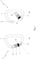
- the first figure shows a connector indicated as a whole with the reference numeral 1, in accordance with the invention.
- the connector 1 has a general substantially "D"-profile but could be configured differently, for example circular, oval, oblong and anything else known in the art.
- the connector comprises a lever finger 2, oscillating with respect to a fulcrum 3 located at one end 5a of the hook-shaped body 5 of the connector; the free end 2a of the oscillating finger 2 is intended to rest on the second end 5b of the hook-shaped body 5 of the connector 1, in the closed condition of the latter.
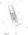
- the finger 2 oscillates in opposition to the elastic action of a spring 7 housed therein, which when at rest keeps the finger 2 in a closed condition ( fig. 3 ).
- a security screwgate 10 of the connector 1 which is also movable between an advanced condition for locking the finger 2 in the closed condition ( fig. 3 ), and a retracted position in which it allows the oscillations of the lever finger 2 (as in fig. 1 ).
- the screwgate 10 and the finger 2 are mutually coupled by means of an interlock and spring mechanism 8; the screwgate 10 is also preferably provided with an external knurling 13, which facilitates its grip with the phalanges of a user's fingers.
- the screwgate 10 and the finger 2 can be coupled by means of a thread.
- an element or tag 15 for radio-frequency proximity communications (e.g., NFC) is applied on the screwgate 10.
- NFC radio-frequency proximity communications
- proximity communication is a receiving/transmitting technology that provides wireless, contactless connectivity between a transmitter and a receiver, via short-range radio frequencies RF) (usually up to a maximum of 10 cm).
- RF radio frequencies
- the technology enables a two-way communication: when two apparatuses, circuits or devices (also called initiator and target ) are brought closer within a few centimetres (typically 4 cm), a peer-to-peer network is created between the two apparatuses and both can send and receive information.
- the technology usually operates at a frequency of 13.56 MHz and can reach a maximum data rate of 424 kbits/s.
- NFC can be implemented directly via an integrated circuit (chip), or via a special external card that is connected to the initiator device.
- the tag 15 is configured in the form of a ring 16 made of polymeric (e.g. polypropylene, ABS, polyethylene) or elastomeric material (e.g. silicone, polyurethane, rubber) or comprising an elastomeric matrix, so as to be resistant to external agents (water, dust, humidity, electrostaticity, etc.) and suitable for absorbing shocks or various stresses, protecting the electronic circuit(s) 17 embedded therein.
- the ring 16 has a thickness such that it is flush with the outer one of the adjacent parts of the screwgate 10, such as the knurling 13 and the tang 10a.
- annular groove 18 having a depth substantially equal to the radial thickness of the ring 16, so that the latter can be housed inside the groove 18.
- the presence of the tag 15 allows information to be exchanged with the electronic circuit 17 inside it; this information may be of various kinds, for example a unique code of the tag, a number, batch and/or date of manufacture, the owner of the connector 1, or even the number of times and/or the time of use and so on.
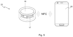
- the radio-frequency devices are capable of two-way communication with appropriate transceivers, today also consisting of mobile phones 20, as schematically shown in figure 5 .
- the data contained in the electronic circuit 17 of the tag 15 can therefore be read whenever desired, with a normal computer reader or even a portable device 20.
- the data can also be updated in the same way, i.e., via a transceiving apparatus, exploiting the two-way characteristic of the proximity communication.
- the positioning of the tag 15 on the screwgate 10 allows to limit the stresses to which it is subjected, since in the use of the connector the screwgate 10, being arranged on the closing finger 2, is not particularly stressed by the ropes, pulleys, descenders, harnesses or other tools, which are used with the connector to secure people in working or mountaineering manoeuvres.
Landscapes
- Engineering & Computer Science (AREA)
- General Engineering & Computer Science (AREA)
- Microelectronics & Electronic Packaging (AREA)
- Mechanical Engineering (AREA)
- Computer Hardware Design (AREA)
- Physics & Mathematics (AREA)
- General Physics & Mathematics (AREA)
- Theoretical Computer Science (AREA)
- Casings For Electric Apparatus (AREA)
- Details Of Connecting Devices For Male And Female Coupling (AREA)
- Mechanical Coupling Of Light Guides (AREA)
- Connector Housings Or Holding Contact Members (AREA)
Description
- The present invention relates to a connector of the type intended for the assembly of fall prevention and/or protection systems for works at height for persons, such as on construction sites, in maintenance operations at height, in technical rescue, and for the assembly of fall prevention and/or protection systems in mountaineering including climbing, in leisure time, such as in amusement parks with elevated paths.
- As is well known, the connector is substantially a special metal hook or ring of varying shape and size, fitted with a spring element that ensures the closure of the hook itself, which, when closed, takes on the characteristics of a ring.
- Generally used for hanging, suspending or preventing bodies from falling, it is particularly useful in mountaineering, where it is indispensable for manoeuvres that are to be performed on the wall, but also in all the numerous rescue, maintenance, construction, repair, cleaning and similar operations, which are carried out at height on buildings, in various civil and industrial buildings, including by airplanes or helicopters.
- Think of the maintenance and the cleaning of the facades of skyscrapers, but also of the interventions on wind turbines or on remote transmission antennas, of the rescue and salvaging operations in the mountains or by firefighters.
- Within these applications there is a wide variety of connectors, both in terms of shape, size and materials.
- The invention applies to all of these variants, but of particular interest here are connectors having an opening locking mechanism (commonly known as a "screwgate"), the latter being a bushing that can be arranged in a non-operational position in which it allows the connector to be opened by moving its elastically oscillating lever, and in a position in which it locks the lever while keeping the connector closed (usually the normal position and used to support forces).
- The screwgate can be manually operated (e.g. by screw) or automatically operated by a spring (e.g. two- or three-movement snap closure); this system serves, once closed, to prevent an accidental opening of the connector lever. This is advantageous for the normal manoeuvres envisaged by the techniques of use, such as self-belaying during a stop and when manoeuvring a person up a wall or in any case in an exposed condition.
- In fact, if the connector were positioned by turning the arm with the lever in contact with a surface (of the user, of other devices, of the structures, of the rock), movements could involuntarily open the lever, generating a situation of risk or even of fall of the user. The lever locked with screwgate allows to overcome this problem.
- The connectors are subject to precise technical standards regarding their mechanical properties, such as mechanical strengths, shapes and surface state, the information to be affixed, the requirements of the mechanisms.
- The climbing and mountaineering connectors, as well as those for occupational and civil use, are considered as personal protective equipment and are certified according to the relevant standards; in Europe the standards are harmonised with the European regulations and directives in force (e.g. EN 362 and EN 12275), while in the rest of the world the requirements vary locally and according to technical standards of the sector (e.g. ANSI/ASSP Z359 and CSA Z259 Fall Protection Code, NFPA 1983).
- The climbing and mountaineering connectors can also bear the international mark UIAA, the documentation for which is in the public domain: the latter provides for more restrictive constraints on manufacturers aimed at ensuring additional safety thanks to continuously updated information from users, associations, manufacturers, and laboratories all over the world, and not restricted to the European context.
- To help recognise the qualities required of such a tiny object, following the main strengths required according to the UIAA mountaineering regulation, the minimum required breaking loads vary according to the intended use of the connector: along the longitudinal axis (i.e. in the same direction as the long side of the connector) with closed lever it can vary between 20 and 25 kN, while the longitudinal one with open lever between 5 and 7 kN, and the one in the transverse direction between 7 and 10 kN. However, there are connectors with different breaking loads, depending on the needs.
- By global agreement there is therefore the need to continuously monitor the status of the connector, both during use and during storage. These aspects are also regulated by various regulations (EN 365 in Europe) which require the manufacturer to provide knowledge for the checks and the user to carry them out according to the information received.
- However, this and other important information relating to the characteristics of the connectors is not readily and immediately available to users.
- In fact, connectors are generally stamped with the minimum necessary information that can be received on the limited available surface (e.g. longitudinal strength, reference technical standard for their determination, traceability information, mark of conformity to the target market), but this refers to the product under new conditions and therefore after a few years of use the properties of a connector may be reduced by the use that has been made thereof.
- In addition, the connectors can be interchanged or mixed up among people, so that while apparently similar, they may have different characteristics related to age, use, storage conditions, preventing the lean traceability in the supply chain required by the market regulations. It is also possible to re-use the connectors that have been sold and are destined for disposal because they do not comply with the prescribed checks.
- There is therefore a general need for more comprehensive information on personal protective equipment such as the connectors that are of interest herein, in order to achieve a better level of safety and reliability than what is currently the case, also available to the users themselves, whether they are employed by large companies or private individuals.
- To meet this need, one could think of stamping this information on the metal of the connectors, but this alters their strength capacity, especially if carried out hot, and it is impossible to apply all the required information legibly.
- On the other hand, one could also think, as an alternative, of applying adhesive labels: however, in addition to not being reliable due to the fact that the labels can be written by anyone, they are however easily subject to damages or detachments due to shocks, scratches, water and other causes, which might make them illegible or useless. The labels can then be removed and applied to another connector and would often turn out to be larger than the connector itself.
- The technical problem underlying the invention is therefore that of making available a connector, i.e., a personal safety device typically made of metal material or in any case with high strength, which can be reliably associated with information relating to its identification and/or use, so as to achieve a better level of safety than similar known safety devices.
- The idea of solving this problem is to associate a radio-frequency electronic device (e.g., of the so-called NFC type, an acronym for the term Near Field Communication) with the connector, so as to allow the computerised recognition and to receive and transmit information in a secure manner via a signalling apparatus electromagnetically coupled with it. One prior art connector using radio-frequency identification (RFID) tagging is known from
EP 3 156 672 A1 - A connector according to
claim 1 is provided. The radio-frequency device is applied on the screwgate of the connector, as this allows the positioning of the connector in a less stressed area and easily accessible for short distance communications. - In addition, the radio-frequency device is arranged in a groove or recess of the connector screwgate, so that it is partially covered and protected from shocks, scratches and the like.
- These and other features of the invention are set forth more specifically in the claims appended to this description.
- These features, the effects resulting therefrom and the advantages achieved by the invention, will be more apparent from the description below of an example embodiment thereof, illustrated with reference to the attached figures provided by way of indication and not limitation, wherein:
-
Fig. 1 (a)-(b) shows a connector in accordance with the invention, in a closed and open condition, respectively; -
Fig. 2 shows the connector screwgate ofFig. 1 ; -
Fig. 3 is a partial sectional view of the connector screwgate infigure 1 ; -
Fig. 4 is an enlarged view of a detail inFig. 3 ; -
Fig. 5 is a diagram of another detail of the previous connector. - With reference to the drawings listed above, the first figure shows a connector indicated as a whole with the
reference numeral 1, in accordance with the invention. - The
connector 1 has a general substantially "D"-profile but could be configured differently, for example circular, oval, oblong and anything else known in the art. - The connector comprises a
lever finger 2, oscillating with respect to afulcrum 3 located at oneend 5a of the hook-shaped body 5 of the connector; thefree end 2a of the oscillatingfinger 2 is intended to rest on thesecond end 5b of the hook-shaped body 5 of theconnector 1, in the closed condition of the latter. - The
finger 2 oscillates in opposition to the elastic action of aspring 7 housed therein, which when at rest keeps thefinger 2 in a closed condition (fig. 3 ). - On the
finger 2 there is applied asecurity screwgate 10 of theconnector 1, which is also movable between an advanced condition for locking thefinger 2 in the closed condition (fig. 3 ), and a retracted position in which it allows the oscillations of the lever finger 2 (as infig. 1 ). - For this purpose, the
screwgate 10 and thefinger 2 are mutually coupled by means of an interlock andspring mechanism 8; thescrewgate 10 is also preferably provided with anexternal knurling 13, which facilitates its grip with the phalanges of a user's fingers. As an alternative to (or in combination with) thespring mechanism 8, thescrewgate 10 and thefinger 2 can be coupled by means of a thread. - In accordance with the invention, an element or
tag 15 for radio-frequency proximity communications (e.g., NFC) is applied on thescrewgate 10. - As is well known, proximity communication is a receiving/transmitting technology that provides wireless, contactless connectivity between a transmitter and a receiver, via short-range radio frequencies RF) (usually up to a maximum of 10 cm). For the sake of brevity, reference is made to the extensive technical and scientific literature on the subject, citing as one of the first examples of this type of device the one described in
US patent 4,384,288 . - The technology enables a two-way communication: when two apparatuses, circuits or devices (also called initiator and target) are brought closer within a few centimetres (typically 4 cm), a peer-to-peer network is created between the two apparatuses and both can send and receive information.
- The technology usually operates at a frequency of 13.56 MHz and can reach a maximum data rate of 424 kbits/s.
- NFC can be implemented directly via an integrated circuit (chip), or via a special external card that is connected to the initiator device.
- Preferably, in the
connector 1 thetag 15 is configured in the form of aring 16 made of polymeric (e.g. polypropylene, ABS, polyethylene) or elastomeric material (e.g. silicone, polyurethane, rubber) or comprising an elastomeric matrix, so as to be resistant to external agents (water, dust, humidity, electrostaticity, etc.) and suitable for absorbing shocks or various stresses, protecting the electronic circuit(s) 17 embedded therein. According to a preferred embodiment, thering 16 has a thickness such that it is flush with the outer one of the adjacent parts of thescrewgate 10, such as the knurling 13 and thetang 10a. - For this purpose, in the
screwgate 10 there is anannular groove 18 having a depth substantially equal to the radial thickness of thering 16, so that the latter can be housed inside thegroove 18. - From the foregoing, it is possible to understand how the
connector 1 solves the technical problem underlying the invention outlined above. - In fact, the presence of the
tag 15 allows information to be exchanged with theelectronic circuit 17 inside it; this information may be of various kinds, for example a unique code of the tag, a number, batch and/or date of manufacture, the owner of theconnector 1, or even the number of times and/or the time of use and so on. - As already explained, in fact, the radio-frequency devices are capable of two-way communication with appropriate transceivers, today also consisting of
mobile phones 20, as schematically shown infigure 5 . - The data contained in the
electronic circuit 17 of thetag 15 can therefore be read whenever desired, with a normal computer reader or even aportable device 20. - The data can also be updated in the same way, i.e., via a transceiving apparatus, exploiting the two-way characteristic of the proximity communication.
- Obviously, these functions can be increased and can be integrated with other solutions. For example, one might think of including among the data in the
tag 15 also those for linking to an Internet page or website or database, in order to expand the content and the amount of information that can be consulted. - In this case, when the
tag 15 on the connector is read with a mobile phone, the opening of a document or of an application on the Internet network is activated where the information can be consulted. - It should also be pointed out that the positioning of the
tag 15 on thescrewgate 10 allows to limit the stresses to which it is subjected, since in the use of the connector thescrewgate 10, being arranged on theclosing finger 2, is not particularly stressed by the ropes, pulleys, descenders, harnesses or other tools, which are used with the connector to secure people in working or mountaineering manoeuvres. - Any stresses on the
connector 1 caused by shocks, falls and the like are in no case transmitted to thering 16 arranged on thescrewgate 10 and nor to thefinger 2 or thebody 5 of the connector. - On the basis of these teachings, the persons skilled in the art will be able to develop or implement further functions and characteristics of the connector.
- For example, the use of RFID tags or other solutions equivalent to the proximity communication technology is believed to fall within the scope of this teaching.
Claims (4)
- Connector (2) comprising a hook-shaped body (5), a finger (2) connected to the hook-shaped body (5) and oscillating between a closed condition, in which it is engaged with one end (5b) of the body (5), and an open condition, in which it is separate from the same, in opposition to the elastic action of a spring (7), a screwgate (10) coupled with the oscillating finger (2) for locking the latter in the closed position, a proximity communication element or tag (15) associated with the screwgate (10),
characterized in that the proximity communication element or tag (15) is substantially configured as a ring (16), wherein the ring (16) is housed in an annular groove (18) formed inside or outside the screwgate (10), having a depth substantially equal to the radial thickness of the ring (16), so that the latter can be housed inside the groove (18). - Connector according to claim 1, wherein the proximity communication element or tag (15) is of the radio-frequency type, preferably Near Field Communication (NFC).
- Connector according to claims 1 or 2, wherein the element or tag (15) comprises an electronic circuit (17) integrated into or associated with a polymeric or elastomeric layer (16).
- Connector according to any of the preceding claims, wherein the ring (16) has a thickness such that it is flush with the outer one of the adjacent parts of the screwgate (10), such as the knurling (13) and the tang (10a).
Applications Claiming Priority (1)
| Application Number | Priority Date | Filing Date | Title |
|---|---|---|---|
| IT102021000010391A IT202100010391A1 (en) | 2021-04-23 | 2021-04-23 | CONNECTOR WITH FERRULE |
Publications (3)
| Publication Number | Publication Date |
|---|---|
| EP4080067A1 EP4080067A1 (en) | 2022-10-26 |
| EP4080067C0 EP4080067C0 (en) | 2024-09-04 |
| EP4080067B1 true EP4080067B1 (en) | 2024-09-04 |
Family
ID=76921161
Family Applications (1)
| Application Number | Title | Priority Date | Filing Date |
|---|---|---|---|
| EP21200755.3A Active EP4080067B1 (en) | 2021-04-23 | 2021-10-04 | Connector with gate |
Country Status (3)
| Country | Link |
|---|---|
| US (1) | US12526937B2 (en) |
| EP (1) | EP4080067B1 (en) |
| IT (1) | IT202100010391A1 (en) |
Cited By (1)
| Publication number | Priority date | Publication date | Assignee | Title |
|---|---|---|---|---|
| US12608580B1 (en) | 2025-04-16 | 2026-04-21 | Scannable NZ Limited | Grommet identifier tag |
Families Citing this family (1)
| Publication number | Priority date | Publication date | Assignee | Title |
|---|---|---|---|---|
| US11814175B1 (en) * | 2022-11-22 | 2023-11-14 | Autoflight (Kunshan) Co., Ltd. | Unmanned aerial vehicle (UAV) delivery structure |
Family Cites Families (12)
| Publication number | Priority date | Publication date | Assignee | Title |
|---|---|---|---|---|
| US4384288A (en) | 1980-12-31 | 1983-05-17 | Walton Charles A | Portable radio frequency emitting identifier |
| FR2731255B1 (en) * | 1995-03-02 | 1997-04-25 | Zedel | LOCKING RING CARABINER |
| US6912836B2 (en) * | 2003-12-01 | 2005-07-05 | Dong Guan Bright Yinhuey Lighting Co., Ltd. China | Hanging chain structure for pendent lamp |
| US20050246874A1 (en) * | 2004-05-10 | 2005-11-10 | Hsu Samuel W | Carabiner with improved gate structure |
| DE602007003900D1 (en) * | 2006-06-26 | 2010-02-04 | Tony Christianson | Snap snap hook |
| US8474112B2 (en) * | 2009-07-29 | 2013-07-02 | Rock Exotica Llc | Carabiners with multi mode locking sleeves, methods of manufacturing such carabiners, and methods of using such carabiners |
| FR2976638B1 (en) * | 2011-06-16 | 2013-07-05 | Wichard | SAFETY CARGO |
| US8621728B2 (en) * | 2011-08-09 | 2014-01-07 | Tony Christianson | Locking carabiner |
| TWM452269U (en) * | 2012-09-25 | 2013-05-01 | Neng-Yuan Ye | Safety hook structure |
| US9322428B2 (en) * | 2013-03-01 | 2016-04-26 | D B Industries, Llc | Locking carabiner |
| US9480866B2 (en) * | 2014-10-21 | 2016-11-01 | The Boeing Company | Line connector having a link detection system and method of making same |
| GB2545879B (en) * | 2015-10-16 | 2018-04-18 | Dmm Int Ltd | Identification of items |
-
2021
- 2021-04-23 IT IT102021000010391A patent/IT202100010391A1/en unknown
- 2021-10-04 EP EP21200755.3A patent/EP4080067B1/en active Active
- 2021-10-29 US US17/514,876 patent/US12526937B2/en active Active
Cited By (1)
| Publication number | Priority date | Publication date | Assignee | Title |
|---|---|---|---|---|
| US12608580B1 (en) | 2025-04-16 | 2026-04-21 | Scannable NZ Limited | Grommet identifier tag |
Also Published As
| Publication number | Publication date |
|---|---|
| US12526937B2 (en) | 2026-01-13 |
| EP4080067C0 (en) | 2024-09-04 |
| EP4080067A1 (en) | 2022-10-26 |
| IT202100010391A1 (en) | 2022-10-23 |
| US20220346254A1 (en) | 2022-10-27 |
Similar Documents
| Publication | Publication Date | Title |
|---|---|---|
| US12526937B2 (en) | Connector with gate | |
| AU2021200993B2 (en) | A wearable rfid system | |
| JP5822796B2 (en) | IC tag housing structure to hook for safety belt | |
| CN101796528B (en) | Retroreflection Limited Tags | |
| KR101308802B1 (en) | Method of controlling access to an area accessible by persons, particularly to a space closed by a door | |
| CN105243414A (en) | Wearable tag capable of wireless communications | |
| CA2553587C (en) | Method of controlling access to an area accessible by persons, particularly to a space closed by a door | |
| WO2005101977A3 (en) | Multi-factor security system with portable devices and security kernels | |
| CN107124197A (en) | A kind of mobile terminal Notification Method and system based on wearable device | |
| CN205541017U (en) | Wirelessly electronic lock of locking is locked and relieved | |
| CN102236817A (en) | RFID (Radio Frequency Identification) managing system for jailhouses | |
| CN108337018A (en) | Communication device and method for manufacturing the same | |
| HRP20050302A2 (en) | System for controlling and managing docking in a sea area | |
| KR100664370B1 (en) | Automatic identification of ship aboard personnel and safety management system | |
| AU2012299447B2 (en) | RFID remote antenna security system | |
| CN107563240B (en) | Wearable device integrated electronic tag data analysis method and system | |
| CN201331767Y (en) | Personnel identifying card based on RFID | |
| CN217061058U (en) | Electroless NFC lock | |
| CN204117218U (en) | For code translator and the finger ring of portable type carrier | |
| KR20160067422A (en) | Near Field Communication Touch-Pad | |
| CA2470611A1 (en) | Method and system for identification | |
| WO2024018325A1 (en) | Composite connector comprising deformable section with interruptible signal-transmissive pathway | |
| Area | Relocation of remote weather station | |
| KR20180103577A (en) | Rfid tag | |
| EP1605672B8 (en) | Enhanced security for voice mail passwords |
Legal Events
| Date | Code | Title | Description |
|---|---|---|---|
| PUAI | Public reference made under article 153(3) epc to a published international application that has entered the european phase |
Free format text: ORIGINAL CODE: 0009012 |
|
| STAA | Information on the status of an ep patent application or granted ep patent |
Free format text: STATUS: THE APPLICATION HAS BEEN PUBLISHED |
|
| AK | Designated contracting states |
Kind code of ref document: A1 Designated state(s): AL AT BE BG CH CY CZ DE DK EE ES FI FR GB GR HR HU IE IS IT LI LT LU LV MC MK MT NL NO PL PT RO RS SE SI SK SM TR |
|
| STAA | Information on the status of an ep patent application or granted ep patent |
Free format text: STATUS: REQUEST FOR EXAMINATION WAS MADE |
|
| 17P | Request for examination filed |
Effective date: 20230419 |
|
| RBV | Designated contracting states (corrected) |
Designated state(s): AL AT BE BG CH CY CZ DE DK EE ES FI FR GB GR HR HU IE IS IT LI LT LU LV MC MK MT NL NO PL PT RO RS SE SI SK SM TR |
|
| GRAP | Despatch of communication of intention to grant a patent |
Free format text: ORIGINAL CODE: EPIDOSNIGR1 |
|
| STAA | Information on the status of an ep patent application or granted ep patent |
Free format text: STATUS: GRANT OF PATENT IS INTENDED |
|
| RIC1 | Information provided on ipc code assigned before grant |
Ipc: F16B 45/02 20060101ALI20240321BHEP Ipc: F16B 1/00 20060101AFI20240321BHEP |
|
| INTG | Intention to grant announced |
Effective date: 20240416 |
|
| GRAS | Grant fee paid |
Free format text: ORIGINAL CODE: EPIDOSNIGR3 |
|
| GRAA | (expected) grant |
Free format text: ORIGINAL CODE: 0009210 |
|
| STAA | Information on the status of an ep patent application or granted ep patent |
Free format text: STATUS: THE PATENT HAS BEEN GRANTED |
|
| AK | Designated contracting states |
Kind code of ref document: B1 Designated state(s): AL AT BE BG CH CY CZ DE DK EE ES FI FR GB GR HR HU IE IS IT LI LT LU LV MC MK MT NL NO PL PT RO RS SE SI SK SM TR |
|
| REG | Reference to a national code |
Ref country code: GB Ref legal event code: FG4D |
|
| REG | Reference to a national code |
Ref country code: CH Ref legal event code: EP |
|
| REG | Reference to a national code |
Ref country code: IE Ref legal event code: FG4D |
|
| REG | Reference to a national code |
Ref country code: DE Ref legal event code: R096 Ref document number: 602021018230 Country of ref document: DE |
|
| U01 | Request for unitary effect filed |
Effective date: 20240920 |
|
| U07 | Unitary effect registered |
Designated state(s): AT BE BG DE DK EE FI FR IT LT LU LV MT NL PT RO SE SI Effective date: 20241030 |
|
| U20 | Renewal fee for the european patent with unitary effect paid |
Year of fee payment: 4 Effective date: 20241028 |
|
| PG25 | Lapsed in a contracting state [announced via postgrant information from national office to epo] |
Ref country code: NO Free format text: LAPSE BECAUSE OF FAILURE TO SUBMIT A TRANSLATION OF THE DESCRIPTION OR TO PAY THE FEE WITHIN THE PRESCRIBED TIME-LIMIT Effective date: 20241204 |
|
| PG25 | Lapsed in a contracting state [announced via postgrant information from national office to epo] |
Ref country code: GR Free format text: LAPSE BECAUSE OF FAILURE TO SUBMIT A TRANSLATION OF THE DESCRIPTION OR TO PAY THE FEE WITHIN THE PRESCRIBED TIME-LIMIT Effective date: 20241205 Ref country code: PL Free format text: LAPSE BECAUSE OF FAILURE TO SUBMIT A TRANSLATION OF THE DESCRIPTION OR TO PAY THE FEE WITHIN THE PRESCRIBED TIME-LIMIT Effective date: 20240904 |
|
| PG25 | Lapsed in a contracting state [announced via postgrant information from national office to epo] |
Ref country code: HR Free format text: LAPSE BECAUSE OF FAILURE TO SUBMIT A TRANSLATION OF THE DESCRIPTION OR TO PAY THE FEE WITHIN THE PRESCRIBED TIME-LIMIT Effective date: 20240904 |
|
| PG25 | Lapsed in a contracting state [announced via postgrant information from national office to epo] |
Ref country code: ES Free format text: LAPSE BECAUSE OF FAILURE TO SUBMIT A TRANSLATION OF THE DESCRIPTION OR TO PAY THE FEE WITHIN THE PRESCRIBED TIME-LIMIT Effective date: 20240904 Ref country code: RS Free format text: LAPSE BECAUSE OF FAILURE TO SUBMIT A TRANSLATION OF THE DESCRIPTION OR TO PAY THE FEE WITHIN THE PRESCRIBED TIME-LIMIT Effective date: 20241204 |
|
| PG25 | Lapsed in a contracting state [announced via postgrant information from national office to epo] |
Ref country code: RS Free format text: LAPSE BECAUSE OF FAILURE TO SUBMIT A TRANSLATION OF THE DESCRIPTION OR TO PAY THE FEE WITHIN THE PRESCRIBED TIME-LIMIT Effective date: 20241204 Ref country code: PL Free format text: LAPSE BECAUSE OF FAILURE TO SUBMIT A TRANSLATION OF THE DESCRIPTION OR TO PAY THE FEE WITHIN THE PRESCRIBED TIME-LIMIT Effective date: 20240904 Ref country code: NO Free format text: LAPSE BECAUSE OF FAILURE TO SUBMIT A TRANSLATION OF THE DESCRIPTION OR TO PAY THE FEE WITHIN THE PRESCRIBED TIME-LIMIT Effective date: 20241204 Ref country code: HR Free format text: LAPSE BECAUSE OF FAILURE TO SUBMIT A TRANSLATION OF THE DESCRIPTION OR TO PAY THE FEE WITHIN THE PRESCRIBED TIME-LIMIT Effective date: 20240904 Ref country code: GR Free format text: LAPSE BECAUSE OF FAILURE TO SUBMIT A TRANSLATION OF THE DESCRIPTION OR TO PAY THE FEE WITHIN THE PRESCRIBED TIME-LIMIT Effective date: 20241205 Ref country code: ES Free format text: LAPSE BECAUSE OF FAILURE TO SUBMIT A TRANSLATION OF THE DESCRIPTION OR TO PAY THE FEE WITHIN THE PRESCRIBED TIME-LIMIT Effective date: 20240904 |
|
| PG25 | Lapsed in a contracting state [announced via postgrant information from national office to epo] |
Ref country code: IS Free format text: LAPSE BECAUSE OF FAILURE TO SUBMIT A TRANSLATION OF THE DESCRIPTION OR TO PAY THE FEE WITHIN THE PRESCRIBED TIME-LIMIT Effective date: 20250104 |
|
| PG25 | Lapsed in a contracting state [announced via postgrant information from national office to epo] |
Ref country code: SM Free format text: LAPSE BECAUSE OF FAILURE TO SUBMIT A TRANSLATION OF THE DESCRIPTION OR TO PAY THE FEE WITHIN THE PRESCRIBED TIME-LIMIT Effective date: 20240904 |
|
| PG25 | Lapsed in a contracting state [announced via postgrant information from national office to epo] |
Ref country code: CZ Free format text: LAPSE BECAUSE OF FAILURE TO SUBMIT A TRANSLATION OF THE DESCRIPTION OR TO PAY THE FEE WITHIN THE PRESCRIBED TIME-LIMIT Effective date: 20240904 |
|
| PG25 | Lapsed in a contracting state [announced via postgrant information from national office to epo] |
Ref country code: SK Free format text: LAPSE BECAUSE OF FAILURE TO SUBMIT A TRANSLATION OF THE DESCRIPTION OR TO PAY THE FEE WITHIN THE PRESCRIBED TIME-LIMIT Effective date: 20240904 |
|
| REG | Reference to a national code |
Ref country code: CH Ref legal event code: PL |
|
| PG25 | Lapsed in a contracting state [announced via postgrant information from national office to epo] |
Ref country code: MC Free format text: LAPSE BECAUSE OF FAILURE TO SUBMIT A TRANSLATION OF THE DESCRIPTION OR TO PAY THE FEE WITHIN THE PRESCRIBED TIME-LIMIT Effective date: 20240904 |
|
| PLBE | No opposition filed within time limit |
Free format text: ORIGINAL CODE: 0009261 |
|
| STAA | Information on the status of an ep patent application or granted ep patent |
Free format text: STATUS: NO OPPOSITION FILED WITHIN TIME LIMIT |
|
| PG25 | Lapsed in a contracting state [announced via postgrant information from national office to epo] |
Ref country code: CH Free format text: LAPSE BECAUSE OF NON-PAYMENT OF DUE FEES Effective date: 20241031 |
|
| 26N | No opposition filed |
Effective date: 20250605 |
|
| PG25 | Lapsed in a contracting state [announced via postgrant information from national office to epo] |
Ref country code: IE Free format text: LAPSE BECAUSE OF NON-PAYMENT OF DUE FEES Effective date: 20241004 |
|
| U20 | Renewal fee for the european patent with unitary effect paid |
Year of fee payment: 5 Effective date: 20251010 |
|
| PG25 | Lapsed in a contracting state [announced via postgrant information from national office to epo] |
Ref country code: CY Free format text: LAPSE BECAUSE OF FAILURE TO SUBMIT A TRANSLATION OF THE DESCRIPTION OR TO PAY THE FEE WITHIN THE PRESCRIBED TIME-LIMIT; INVALID AB INITIO Effective date: 20211004 |
|
| PG25 | Lapsed in a contracting state [announced via postgrant information from national office to epo] |
Ref country code: HU Free format text: LAPSE BECAUSE OF FAILURE TO SUBMIT A TRANSLATION OF THE DESCRIPTION OR TO PAY THE FEE WITHIN THE PRESCRIBED TIME-LIMIT; INVALID AB INITIO Effective date: 20211004 |