EP4080020A1 - Internal combustion engine and straddled vehicle - Google Patents
Internal combustion engine and straddled vehicle Download PDFInfo
- Publication number
- EP4080020A1 EP4080020A1 EP21213407.6A EP21213407A EP4080020A1 EP 4080020 A1 EP4080020 A1 EP 4080020A1 EP 21213407 A EP21213407 A EP 21213407A EP 4080020 A1 EP4080020 A1 EP 4080020A1
- Authority
- EP
- European Patent Office
- Prior art keywords
- oil
- side wall
- internal combustion
- combustion engine
- vehicle
- Prior art date
- Legal status (The legal status is an assumption and is not a legal conclusion. Google has not performed a legal analysis and makes no representation as to the accuracy of the status listed.)
- Granted
Links
Images


Classifications
-
- F—MECHANICAL ENGINEERING; LIGHTING; HEATING; WEAPONS; BLASTING
- F01—MACHINES OR ENGINES IN GENERAL; ENGINE PLANTS IN GENERAL; STEAM ENGINES
- F01M—LUBRICATING OF MACHINES OR ENGINES IN GENERAL; LUBRICATING INTERNAL COMBUSTION ENGINES; CRANKCASE VENTILATING
- F01M1/00—Pressure lubrication
- F01M1/02—Pressure lubrication using lubricating pumps
-
- F—MECHANICAL ENGINEERING; LIGHTING; HEATING; WEAPONS; BLASTING
- F01—MACHINES OR ENGINES IN GENERAL; ENGINE PLANTS IN GENERAL; STEAM ENGINES
- F01M—LUBRICATING OF MACHINES OR ENGINES IN GENERAL; LUBRICATING INTERNAL COMBUSTION ENGINES; CRANKCASE VENTILATING
- F01M11/00—Component parts, details or accessories, not provided for in, or of interest apart from, groups F01M1/00 - F01M9/00
- F01M11/0004—Oilsumps
-
- F—MECHANICAL ENGINEERING; LIGHTING; HEATING; WEAPONS; BLASTING
- F01—MACHINES OR ENGINES IN GENERAL; ENGINE PLANTS IN GENERAL; STEAM ENGINES
- F01M—LUBRICATING OF MACHINES OR ENGINES IN GENERAL; LUBRICATING INTERNAL COMBUSTION ENGINES; CRANKCASE VENTILATING
- F01M11/00—Component parts, details or accessories, not provided for in, or of interest apart from, groups F01M1/00 - F01M9/00
- F01M11/02—Arrangements of lubricant conduits
-
- B—PERFORMING OPERATIONS; TRANSPORTING
- B62—LAND VEHICLES FOR TRAVELLING OTHERWISE THAN ON RAILS
- B62J—CYCLE SADDLES OR SEATS; AUXILIARY DEVICES OR ACCESSORIES SPECIALLY ADAPTED TO CYCLES AND NOT OTHERWISE PROVIDED FOR, e.g. ARTICLE CARRIERS OR CYCLE PROTECTORS
- B62J31/00—Installations of lubricating devices
-
- B—PERFORMING OPERATIONS; TRANSPORTING
- B62—LAND VEHICLES FOR TRAVELLING OTHERWISE THAN ON RAILS
- B62M—RIDER PROPULSION OF WHEELED VEHICLES OR SLEDGES; POWERED PROPULSION OF SLEDGES OR SINGLE-TRACK CYCLES; TRANSMISSIONS SPECIALLY ADAPTED FOR SUCH VEHICLES
- B62M7/00—Motorcycles characterised by position of motor or engine
-
- F—MECHANICAL ENGINEERING; LIGHTING; HEATING; WEAPONS; BLASTING
- F01—MACHINES OR ENGINES IN GENERAL; ENGINE PLANTS IN GENERAL; STEAM ENGINES
- F01M—LUBRICATING OF MACHINES OR ENGINES IN GENERAL; LUBRICATING INTERNAL COMBUSTION ENGINES; CRANKCASE VENTILATING
- F01M1/00—Pressure lubrication
- F01M1/12—Closed-circuit lubricating systems not provided for in groups F01M1/02 - F01M1/10
- F01M2001/123—Closed-circuit lubricating systems not provided for in groups F01M1/02 - F01M1/10 using two or more pumps
-
- F—MECHANICAL ENGINEERING; LIGHTING; HEATING; WEAPONS; BLASTING
- F01—MACHINES OR ENGINES IN GENERAL; ENGINE PLANTS IN GENERAL; STEAM ENGINES
- F01M—LUBRICATING OF MACHINES OR ENGINES IN GENERAL; LUBRICATING INTERNAL COMBUSTION ENGINES; CRANKCASE VENTILATING
- F01M1/00—Pressure lubrication
- F01M1/12—Closed-circuit lubricating systems not provided for in groups F01M1/02 - F01M1/10
- F01M2001/126—Dry-sumps
-
- F—MECHANICAL ENGINEERING; LIGHTING; HEATING; WEAPONS; BLASTING
- F01—MACHINES OR ENGINES IN GENERAL; ENGINE PLANTS IN GENERAL; STEAM ENGINES
- F01M—LUBRICATING OF MACHINES OR ENGINES IN GENERAL; LUBRICATING INTERNAL COMBUSTION ENGINES; CRANKCASE VENTILATING
- F01M11/00—Component parts, details or accessories, not provided for in, or of interest apart from, groups F01M1/00 - F01M9/00
- F01M11/0004—Oilsumps
- F01M2011/0037—Oilsumps with different oil compartments
-
- F—MECHANICAL ENGINEERING; LIGHTING; HEATING; WEAPONS; BLASTING
- F01—MACHINES OR ENGINES IN GENERAL; ENGINE PLANTS IN GENERAL; STEAM ENGINES
- F01M—LUBRICATING OF MACHINES OR ENGINES IN GENERAL; LUBRICATING INTERNAL COMBUSTION ENGINES; CRANKCASE VENTILATING
- F01M11/00—Component parts, details or accessories, not provided for in, or of interest apart from, groups F01M1/00 - F01M9/00
- F01M11/0004—Oilsumps
- F01M2011/0083—Dry sumps
-
- F—MECHANICAL ENGINEERING; LIGHTING; HEATING; WEAPONS; BLASTING
- F01—MACHINES OR ENGINES IN GENERAL; ENGINE PLANTS IN GENERAL; STEAM ENGINES
- F01M—LUBRICATING OF MACHINES OR ENGINES IN GENERAL; LUBRICATING INTERNAL COMBUSTION ENGINES; CRANKCASE VENTILATING
- F01M11/00—Component parts, details or accessories, not provided for in, or of interest apart from, groups F01M1/00 - F01M9/00
- F01M11/0004—Oilsumps
- F01M2011/0087—Sump being made of different parts
-
- F—MECHANICAL ENGINEERING; LIGHTING; HEATING; WEAPONS; BLASTING
- F01—MACHINES OR ENGINES IN GENERAL; ENGINE PLANTS IN GENERAL; STEAM ENGINES
- F01M—LUBRICATING OF MACHINES OR ENGINES IN GENERAL; LUBRICATING INTERNAL COMBUSTION ENGINES; CRANKCASE VENTILATING
- F01M11/00—Component parts, details or accessories, not provided for in, or of interest apart from, groups F01M1/00 - F01M9/00
- F01M2011/0095—Supplementary oil tank
-
- F—MECHANICAL ENGINEERING; LIGHTING; HEATING; WEAPONS; BLASTING
- F02—COMBUSTION ENGINES; HOT-GAS OR COMBUSTION-PRODUCT ENGINE PLANTS
- F02B—INTERNAL-COMBUSTION PISTON ENGINES; COMBUSTION ENGINES IN GENERAL
- F02B61/00—Adaptations of engines for driving vehicles or for driving propellers; Combinations of engines with gearing
- F02B61/02—Adaptations of engines for driving vehicles or for driving propellers; Combinations of engines with gearing for driving cycles
Definitions
- the present invention relates to an internal combustion engine and a straddled vehicle using dry-sump lubrication.
- An internal combustion engine that uses dry-sump lubrication includes an oil pan, an oil tank, a scavenge pump that pumps oil from the oil pan to the oil tank, and a feed pump that pumps oil from the oil tank to sliding parts of the internal combustion engine.
- the pump volume of the scavenge pump is normally set to be larger than the pump volume of the feed pump.
- the capacity of the scavenge pump is normally set to be larger than the capacity of the feed pump.
- Oil to be transferred from the scavenge pump is stored in the oil tank.
- the load on the scavenge pump becomes high.
- the oil tank is formed to be larger and is set so as not to become full.
- the oil tank is formed to be larger, it leads to an increase in the size of the internal combustion engine.
- An internal combustion engine disclosed herein includes: a case; a crank shaft rotatably supported on the case; a first side wall arranged inside the case to partition the inside of the case into a first chamber and a second chamber; an oil pan provided on a bottom portion of the first chamber to store oil therein; an oil tank formed in the second chamber; a scavenge pump having a first intake port that communicates with the oil pan and a discharge port that communicates with the oil tank; and a feed pump having a second intake port that communicates with the oil tank.
- An oil return hole that connects together the oil tank and the first chamber is formed in an upper portion of the first side wall.
- the oil tank can be made smaller.
- the internal combustion engine may include a guide rib protruding from the first side wall toward the first chamber.
- the guide rib may be formed so as to guide oil, which flows into the first chamber from the oil tank through the oil return hole, into the oil pan.
- the guide rib may include a first rib portion arranged upward relative to a lower end of the oil return hole, and a second rib portion arranged at or below a lower end of the oil return hole.
- the first rib portion and the second rib portion may extend downward.
- the first rib portion and the second rib portion it is possible to suppress scattering of oil, which has flown into the first chamber through the oil return hole. It is possible to smoothly guide oil from the oil return hole into the oil pan.
- the case and the guide rib may together define an oil path that connects together the oil return hole and the oil pan.
- oil which has flown into the first chamber through the oil return hole, is guided into the oil pan through the oil path defined.
- the internal combustion engine may include an intake path that has an inlet facing the oil pan and communicates with the first intake port of the scavenge pump.
- the crank shaft may include a crank web.
- a lower end of the guide rib may be located downward relative to the crank web and upward relative to the inlet of the intake path.
- the guide rib it is possible to suppress fluctuation of the oil surface of the oil pan. Moreover, with the guide rib, it is possible to preferably supply oil to the inlet of the intake path. Thus, the scavenge pump can stably suck in oil.
- the oil return hole may be located forward relative to an axis of the crank shaft.
- the guide rib may include a portion located forward relative to a front end of the oil pan and a portion located rearward relative to the front end of the oil pan.
- the oil return hole may be located upward relative to an axis of the crank shaft.
- the internal combustion engine may include a generator connected to an end portion of the crank shaft.
- the case may have an arc-shaped vertical wall located outward in a radial direction of the generator as viewed from an axis direction of the crank shaft.
- the vertical wall may partition a portion of the oil tank.
- the oil tank is arranged next to the generator.
- the case may include a crank case that rotatably supports the crank shaft.
- the first side wall may be provided in the crank case.
- the case may include a crank case cover having a second side wall arranged sideward of the first side wall.
- the internal combustion engine may include a partition side wall arranged between the first side wall of the crank case and the second side wall of the crank case cover.
- the oil tank may be formed between the first side wall and the partition side wall.
- An auxiliary tank may be formed between the second side wall and the partition side wall.
- An oil tank inlet that connects together the auxiliary tank and the oil tank may be formed between the first side wall and the second side wall.
- the discharge port of the scavenge pump may communicate with the oil tank via the auxiliary tank.
- the discharge port of the scavenge pump communicates with the oil tank via the auxiliary tank
- the flow velocity of oil transferred from the scavenge pump decreases in the auxiliary tank. This suppresses a rapid flow of oil into the oil tank. Gas-liquid separation is performed in the auxiliary tank. Therefore, it is possible to suppress mixing of bubbles in oil in the oil tank.
- the feed pump can more stably supply oil from the oil tank.
- the oil tank inlet may be formed upward of the partition side wall.
- the oil return hole may be formed upward relative to a lower end of an upper edge of the partition side wall.
- the auxiliary tank may be formed so that a flow path cross-sectional area of the auxiliary tank increases gradually in an upward direction.
- the first side wall, the second side wall and the partition side wall may be perpendicular to an axis of the crank shaft.
- a straddled vehicle disclosed herein includes the internal combustion engine.
- FIG. 1 is a right side view of a motorcycle 1, which is an example of a straddled vehicle.
- the motorcycle 1 includes a vehicle body frame 2, an internal combustion engine (hereinafter referred to as an engine) 10 supported on the vehicle body frame 2, a rear wheel 4 driven by the engine 10, a front wheel 5, a fuel tank 6, and a seat 7 in which the rider sits.
- an engine internal combustion engine
- front, rear, left, right, up and down refer to these directions as viewed from a virtual rider seated on a seat 7 while the motorcycle 1 is standing upright on a horizontal surface with no rider and no load thereon, unless specified otherwise.
- the term "forward" refers not only to the direction that extends in the front direction along the vehicle center line, as the vehicle is viewed from above, but also to directions that are inclined from that direction by an angle that is less than 90 degrees in the vehicle left-right direction.
- the term “rearward” refers not only to the direction that extends rearward along the vehicle center line, as the vehicle is viewed from above, but also to directions that are inclined from that direction by an angle that is less than 90 degrees in the vehicle left-right direction.
- the vehicle front-rear direction F-Re extends along the vehicle center line as the vehicle is viewed from above or viewed from the side.
- the term “leftward” refers not only to the direction that extends leftward vertical to the vehicle center line, as the vehicle is viewed from above, but also to directions that are inclined from that direction by an angle that is less than 90 degrees in the vehicle front-rear direction.
- the term “rightward” refers not only to the direction that extends rightward vertical to the vehicle center line, as the vehicle is viewed from above, but also to directions that are inclined from that direction by an angle that is less than 90 degrees in the vehicle front-rear direction.
- the vehicle left-right direction L-R extends in the vehicle width direction as the vehicle is viewed from above or viewed from the front or the rear and relates to the view direction of a rider sitting on the seat of the vehicle.
- the term “upward” refers not only to the vertically upward direction, as the vehicle is viewed from the side, but also to directions that are inclined from that direction by an angle that is less than 90 degrees in the vehicle front-rear direction.
- the term “downward” refers not only to the vertically downward direction, as the vehicle is viewed from the side, but also to directions that are inclined from that direction by an angle that is less than 90 degrees in the vehicle front-rear direction.
- the vehicle up-down direction U-D extends in the vertical direction of the vehicle as the vehicle is viewed from the side or viewed from the front or the rear.
- FIG. 2 is a front view of the engine 10.
- the engine 10 includes a crank case 11, a cylinder body 12 connected to the crank case 11, a cylinder head 13 connected to the cylinder body 12, and a cylinder head cover 14 connected to the cylinder head 13.
- the cylinder body 12 extends upward from the crank case 11.
- the cylinder head 13 extends upward from the cylinder body 12.
- the engine 10 includes a crank case cover 20 connected to the crank case 11.
- the crank case 11 and the crank case cover 20 together form a case 80.
- the crank case cover 20 is arranged sideward of the crank case 11.
- the crank case cover 20 is arranged leftward of the crank case 11.
- An intake port (not shown) and an exhaust port 15 are formed on the cylinder head 13.
- An exhaust pipe 16 is connected to the exhaust port 15.
- a silencer 17 is connected to a rear end portion of the exhaust pipe 16.
- FIG. 3 is a left side view of the crank case 11 and the crank case cover 20 of the engine 10.
- FIG. 4 is a left side view of the crank case 11.
- a gasket 24 is sandwiched between the crank case 11 and the crank case cover 20.
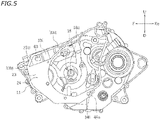
- FIG. 5 is a left side view of the gasket 24 and the crank case 11.
- FIG. 6 is a partial enlarged perspective view showing the inside of the engine 10, with the crank case cover 20 partially removed.
- the engine 10 includes the crank shaft 18.
- the crank shaft 18 is rotatably supported on the crank case 11.
- the crank shaft 18 extends leftward and rightward.
- a straight line 18c represents the axis of the crank shaft 18.
- the crank shaft 18 includes a crank web 18A.
- a generator 19 is connected to an end portion of the crank shaft 18.
- the generator 19 is connected to the left end portion of the crank shaft 18.
- the generator 19 is formed in a generally circular shape.
- the crank case 11 has a first side wall 21.
- the first side wall 21 is a wall that is perpendicular to an axis 18c of the crank shaft 18.
- the first side wall 21 extends in the up-down direction and the front-rear direction.
- FIG. 7 is a cross-sectional view showing an internal configuration of the engine 10 as viewed from the right side.
- a first chamber 31 is defined rightward of the first side wall 21.
- a second chamber 32 is defined leftward of the first side wall 21.
- the first side wall 21 is arranged inside the crank case 11.
- the first side wall 21 partitions the inside of the crank case 11 into the first chamber 31 and the second chamber 32.
- the crank case 11 has a bottom wall 26.
- the bottom wall 26 defines an oil pan 25 that stores lubricating oil (hereinafter referred to as oil).
- oil lubricating oil
- a straight line OL represents an example of the oil surface.
- the oil surface OL may be the oil surface when the motorcycle 1 is stopped standing upright on a horizontal surface and the engine 10 is stopped. Note however that the height of the oil surface OL varies depending on the amount of oil filled in the engine 10. The height of the oil surface OL varies also depending on the operation status of the engine 10.
- the oil pan 25 refers to a portion of the crank case 11 that is at or below the horizontal plane passing through the lowermost end of the crank web 18A. In FIG.
- a one-dot-chain line 25L represents the horizontal surface passing through the lowermost end of the crank web 18A.
- the oil pan 25 refers to a portion of the crank case 11 that is at or below the one-dot-chain line 25L.
- the crank web 18A is formed in a non-circular shape. The position of the lower end of the crank web 18A varies depending on the rotational position of the crank web 18A. The lowermost end of the crank web 18A refers to the lowest end of the lower end of the crank web 18A.
- the oil pan 25 is depressed downward.
- the oil pan 25 is provided on the bottom wall of the first chamber 31.
- the engine 10 is an internal combustion engine using dry-sump lubrication.
- the engine 10 includes a scavenge pump 40.
- the scavenge pump 40 includes an intake port 41 and a discharge port 42.
- the intake port 41 communicates with the oil pan 25 via an intake path 45.
- the intake path 45 includes an intake chamber 45A and a passageway 45B.
- An inlet 45i is formed on the intake chamber 45A. While there is no particular limitation on the position of the inlet 45i, the inlet 45i is herein formed at the front end of the intake chamber 45A.
- the inlet 45i serves as an inlet for the intake path 45.
- the inlet 45i has an opening facing toward the oil pan 25.
- the inlet 45i communicates between the oil pan 25 and the intake chamber 45A.
- the passageway 45B extends upward.
- An opening 45Bi that has an opening facing toward the intake chamber 45A is formed at the lower end of the passageway 45B.
- the scavenge pump 40 transfers oil toward an oil tank 33 to be described later.
- the discharge port 42 of the scavenge pump 40 communicates with the oil tank 33 via a discharge path 46.
- the discharge path 46 includes a passageway 46A extending downward, and a passageway 46B extending leftward from the passageway 46A.
- an outlet 46o of the discharge path 46 is formed on the first side wall 21. The outlet 46o has an opening facing leftward.
- the crank case cover 20 has a second side wall 22 arranged sideward of the first side wall 21.
- the second side wall 22 is arranged leftward of the first side wall 21.
- the second side wall 22 is perpendicular to the axis 18c of the crank shaft 18.
- the second side wall 22 extends in the up-down direction and the front-rear direction.
- the gasket 24 has a partition side wall 23 arranged between the first side wall 21 of the crank case 11 and the second side wall 22 of the crank case cover 20.
- the partition side wall 23 is arranged leftward of the first side wall 21.
- the partition side wall 23 is arranged rightward of the second side wall 22.
- the partition side wall 23 is perpendicular to the axis 18c of the crank shaft 18.
- the partition side wall 23 extends in the up-down direction and the front-rear direction.
- the oil tank 33 is defined between the first side wall 21 and the partition side wall 23.
- the crank case 11 has a front wall 11F, an upper wall 11U, a lower wall 11D and a rear wall 11B.
- the front wall 11F, the upper wall 11U, the lower wall 11D and the rear wall 11B extend leftward.
- An upper end 11 Ft of the front wall 11F and a front end 11Uf of the upper wall 11U are connected together.
- a lower end 11Fd of the front wall 11F and a front end 11Df of the lower wall 11D are connected together.
- An upper end 11Bt of the rear wall 11B and a rear end 11Ub of the upper wall 11U are connected together.
- a lower end 11Bd of the rear wall 11B and a rear end 11Db of the lower wall 11D are connected together.
- the front wall 11F, the upper wall 11U, the lower wall 11D and the rear wall 11B are connected into a loop.
- the oil tank 33 is defined by the first side wall 21, the partition side wall 23, the front wall 11F, the upper wall 11U, the lower wall 11D and the rear wall 11B.
- the oil tank 33 is formed in a front portion of the crank case 11.
- the rear wall 11B has an arc-shaped vertical wall 11 Br located outward in the radial direction of the generator 19, as viewed from the axis direction of the crank shaft 18.
- the vertical wall 11Br defines a part of the oil tank 33.
- the oil tank 33 is arranged next to the generator 19.
- the crank case cover 20 has a front wall 20F, an upper wall 20U, a lower wall 20D and a rear wall 20B corresponding to the front wall 11F, the upper wall 11U, the lower wall 11D and the rear wall 11B of the crank case 11, respectively.
- the front wall 20F, the upper wall 20U, the lower wall 20D and the rear wall 20B extend rightward.
- An upper end 20Ft of the front wall 20F and a front end 20Uf of the upper wall 20U are connected together.
- a lower end 20Fd of the front wall 20F and a front end 20Df of the lower wall 20D are connected together.
- the auxiliary tank 34 is defined by the second side wall 22, the partition side wall 23, the front wall 20F, the upper wall 20U, the lower wall 20D and the rear wall 20B.
- the auxiliary tank 34 is formed in a front portion of the crank case cover 20.
- the rear wall 20B has an arc-shaped vertical wall 20Br located outward in the radial direction of the generator 19, as viewed from the axis direction of the crank shaft 18.
- the vertical wall 20Br defines a part of the auxiliary tank 34.
- the auxiliary tank 34 is arranged next to the generator 19.
- an auxiliary tank inlet 34i is formed on the gasket 24.
- the auxiliary tank inlet 34i is a through hole formed in the gasket 24.
- the auxiliary tank inlet 34i overlaps with the outlet 46o of the discharge path 46 (see FIG. 4 ).
- the auxiliary tank inlet 34i is connected to the outlet 46o of the discharge path 46.
- the auxiliary tank inlet 34i has an opening facing leftward.
- the auxiliary tank inlet 34i is formed in a lower portion of the auxiliary tank 34.
- the auxiliary tank inlet 34i is formed in a rear portion of the auxiliary tank 34.
- an upper edge 23U of the partition side wall 23 is located downward relative to the upper wall 11U of the crank case 11 and the upper wall 20U of the crank case cover 20.
- An oil tank inlet 33i that connects together the auxiliary tank 34 and the oil tank 33 is formed upward of the partition side wall 23. Oil in the auxiliary tank 34 flows into the oil tank 33 by coming over the partition side wall 23.
- the opening area of the oil tank inlet 33i is relatively large. As shown in FIG. 5 , the opening area of the oil tank inlet 33i is larger than the opening area of the auxiliary tank inlet 34i.
- the oil tank inlet 33i is formed upward relative to the auxiliary tank inlet 34i. Oil in the auxiliary tank 34 flows upward toward the oil tank inlet 33i. As shown in FIG. 6 , in the upper half portion of the auxiliary tank 34, the interval in the front-rear direction between the front wall 20F and the rear wall 20B of the crank case cover 20 increases gradually in the upward direction.
- the auxiliary tank 34 is formed so that a flow path cross-sectional area A34 increases gradually in the upward direction.
- the auxiliary tank 34 is formed so that the flow path cross-sectional area A34 increases gradually toward the oil tank inlet 33i.
- an oil tank outlet 33o is formed on the crank case 11.
- the oil tank outlet 33o has an opening facing leftward.
- the oil tank outlet 33o is formed in a lower portion of the oil tank 33.
- the oil tank outlet 33o is formed in a rear portion of the oil tank 33.
- FIG. 8 is an oil circulation circuit diagram.
- the engine 10 includes a feed pump 50 for supplying oil to sliding parts 49 of the engine 10.
- the feed pump 50 includes an intake port 51 and a discharge port 52.
- the oil tank outlet 33o is connected to the intake port 51 of the feed pump 50 via an oil path 47.
- the discharge port 52 of the feed pump 50 communicates with the sliding parts 49 of the engine 10 via an oil path 48.
- an oil return hole 63 that connects together the oil tank 33 and the first chamber 31 is formed in an upper portion of the first side wall 21.
- an upper portion of the first side wall 21 refers to a portion of the first side wall 21 that is upward relative to the middle position thereof in the up-down direction.
- the first side wall 21 defines the right side of the oil tank 33.
- An upper portion of the first side wall 21 may be a portion of the oil tank 33 that is upward relative to the middle position thereof in the up-down direction.
- the oil return hole 63 may be formed at a position that is within 30% of the dimension in the up-down direction of the first side wall 21 from the upper end of the first side wall 21, or may be formed at a position that is within 20%.
- the oil return hole 63 may be formed at a position that is within 30% of the dimension in the up-down direction of the oil tank 33 from the upper end of the oil tank 33, or may be formed at a position that is within 20%.
- the oil return hole 63 is located upward relative to the axis 18c of the crank shaft 18.
- the oil return hole 63 is formed upward relative to a lower end 33id of the oil tank inlet 33i.
- the lower end 33id of the oil tank inlet 33i corresponds to the lower end of the upper edge 23U of the partition side wall 23.
- the oil return hole 63 is formed upward relative to the lower end of the upper edge 23U of the partition side wall 23.
- the oil return hole 63 is formed downward relative to an upper end 33it of the oil tank inlet 33i. Note however that there is no particular limitation on the position of the oil return hole 63 relative to the lower end 33id and the upper end 33it of the oil tank inlet 33i.
- the oil return hole 63 serves to return oil that flows over the oil tank 33 back into the first chamber 31. As indicated by an arrow B63 in FIG. 7 , oil having flown into the first chamber 31 from the oil return hole 63 falls down to be collected in the oil pan 25.
- the first side wall 21 is provided with a guide rib 65 protruding toward the first chamber 31.
- the guide rib 65 protrudes rightward from the first side wall 21.
- the guide rib 65 is formed so as to guide oil, which flows into the first chamber 31 from the oil return hole 63, into the oil pan 25.
- the guide rib 65 includes a first rib portion 65a arranged upward relative to a lower end 63d of the oil return hole 63, and a second rib portion 65b arranged at or below the lower end 63d of the oil return hole 63.
- the first rib portion 65a is arranged rearward of the oil return hole 63.
- the first rib portion 65a and the second rib portion 65b extend downward.
- the first rib portion 65a and the second rib portion 65b are connected together.
- the guide rib 65 includes a third rib portion 65c extending downward and rearward.
- the second rib portion 65b and the third rib portion 65c are connected together.
- the crank case 11 includes another side wall 28 located rightward of the first side wall 21.
- the guide rib 65 may extend from the first side wall 21 to the other side wall 28.
- the guide rib 65 may be connected to, or in contact with, the other side wall 28.
- the guide rib 65 may be spaced apart from the other side wall 28.
- the right end of the guide rib 65 may be located leftward relative to the other side wall 28.
- the oil pan 25 is formed of a portion of the bottom wall 26 of the crank case 11 that is depressed downward.
- a front end 25f of the oil pan 25 is located forward relative to the axis 18c of the crank shaft 18.
- a rear end 25b of the oil pan 25 is located rearward relative to the axis 18c of the crank shaft 18.
- the oil return hole 63 is formed forward relative to the axis 18c of the crank shaft 18.
- the guide rib 65 extends from a position forward relative to the axis 18c of the crank shaft 18 to a position rearward relative to the axis 18c of the crank shaft 18.
- the crank shaft 18 includes the crank web 18A.
- a lower end 65d of the guide rib 65 is located downward relative to the crank web 18A. Note that the crank web 18A moves following the rotation of the crank shaft 18. As used herein, "being located downward relative to the crank web 18A" means being located downward relative to the crank web 18A having moved to the most downward position.
- the lower end 65d of the guide rib 65 is located downward relative to the upper end of the oil pan 25.
- the lower end 65d of the guide rib 65 is arranged upward relative to the inlet 45i of the intake path 45.
- the lower end 65d of the guide rib 65 coincides with the rear end of the guide rib 65.
- the lower end 65d of the guide rib 65 is located rearward relative to the front end 25f of the oil pan 25.
- the lower end 65d of the guide rib 65 is located rearward relative to the foremost end of the crank web 18A.
- the lower end 65d of the guide rib 65 is located forward relative to the rear end 25b of the oil pan 25.
- the lower end 65d of the guide rib 65 is located forward relative to the rearmost end of the crank web 18A.
- the lower end 65d of the guide rib 65 is located forward relative to the intake chamber 45A.
- the lower end 65d of the guide rib 65 is located rearward relative to the middle position between the front end 25f of the oil pan 25 and the intake chamber 45A for the front-rear direction.
- upstream side refers to the side from which oil flows.
- Downstream side refers to the side toward which oil flows.
- the oil pan 25 stores oil therein. As indicated by an arrow in FIG. 8 , oil in the oil pan 25 is sucked into the scavenge pump 40 through the intake path 45. The scavenge pump 40 transfers oil to the auxiliary tank 34 through the discharge path 46. Oil, which has been transferred to the auxiliary tank 34, flows upward in the auxiliary tank 34 and flows into the oil tank 33 through the oil tank inlet 33i.
- oil is not directly transferred from the discharge path 46 to the oil tank 33.
- Oil is once transferred to the auxiliary tank 34, and then transferred to the oil tank 33.
- the flow path cross-sectional area of the auxiliary tank 34 is larger than the flow path cross-sectional area of the discharge path 46.
- the flow velocity of oil is relatively high in the discharge path 46, but it is relatively low in the auxiliary tank 34.
- the flow velocity of oil decreases. Therefore, oil slowly flows into the oil tank 33 from the auxiliary tank 34. This suppresses a rapid flow of oil into the oil tank 33. This suppresses mixing of bubbles in oil in the oil tank 33.
- the auxiliary tank 34 has a gas-liquid separation function. Even if bubbles are mixed in the oil transferred from the discharge path 46, oil and air are separated from each other in the auxiliary tank 34. Oil, from which air has been separated, flows into the oil tank 33. This suppresses mixing of bubbles in oil in the oil tank 33.
- Oil in the oil tank 33 is sucked into the feed pump 50 through the oil path 47.
- the feed pump 50 supplies oil to the sliding parts 49 of the engine 10 through the oil path 48. After lubricating the sliding parts 49, oil returns to the oil pan 25 to be stored in the oil pan 25.
- the oil return hole 63 is formed in the oil tank 33.
- oil in the oil tank 33 flows out through the oil return hole 63. Therefore, it is possible to avoid the oil tank 33 becoming full. This suppresses the load on the scavenge pump 40 from becoming high.
- oil, which has flown into the first chamber 31 from the oil tank 33 through the oil return hole 63, is guided to the oil pan 25 by the guide rib 65. This suppresses scattering of oil, which has flown over the oil tank 33, in the first chamber 31. Oil, which has flown over the oil tank 33, is smoothly guided into the oil pan 25.
- the oil return hole 63 is formed in an upper portion of the first side wall 21. If the amount of oil to be transferred from the scavenge pump 40 to the oil tank 33 increases temporarily, oil flows out from the oil tank 33 through the oil return hole 63. Therefore, there is no need to make the oil tank 33 larger in advance so as to avoid the oil tank 33 becoming full. According to the present embodiment, without making the oil tank 33 larger, it is possible to prevent a large load on the scavenge pump 40. Therefore, it is possible to make the oil tank 33 smaller.
- the guide rib 65 is provided for guiding oil, which flows into the first chamber 31 through the oil return hole 63, into the oil pan 25. Therefore, oil flowing over the oil tank 33 can be smoothly guided into the oil pan 25.
- the guide rib 65 includes the first rib portion 65a arranged upward relative to the lower end 63d of the oil return hole 63, and the second rib portion 65b arranged at or below the lower end 63d of the oil return hole 63.
- the first rib portion 65a and the second rib portion 65b extend downward.
- the front wall 11F and the lower wall 11D of the crank case 11 and the guide rib 65 together define the oil path 66 that connects together the oil return hole 63 and the oil pan 25.
- the oil path 66 it is possible to smoothly guide oil from the oil return hole 63 into the oil pan 25.
- the guide rib 65 extends to a relatively low position.
- the lower end 65d of the guide rib 65 is located downward relative to the crank web 18A and upward relative to the inlet 45i of the intake path 45. Since the lower end 65d is located at a relatively low position, it is possible to suppress fluctuation of the oil surface by the guide rib 65. It is possible to suppress fluctuation of the oil surface, irrespective of fluctuation of pressure caused by the piston (not shown) of the engine 10 moving up and down.
- oil in the oil pan 25 tends to move forward due to an inertial force.
- oil may possibly move temporarily forward from the oil pan 25, but that oil flows into the oil path 66.
- oil is unlikely to scatter upon sudden braking of the motorcycle 1.
- oil quickly returns from the oil path 66 into the oil pan 25. Since the lower end 65d of the guide rib 65 is located upward relative to the inlet 45i of the intake path 45, oil can be quickly supplied from the oil path 66 to the inlet 45i after sudden braking.
- the guide rib 65 extends from a position forward relative to the front end 25f of the oil pan 25 to a position rearward relative to the front end 25f of the oil pan 25.
- the rear end of the guide rib 65 (in the present embodiment, the rear end of the guide rib 65 coincides with the lower end 65d) is located rearward relative to the front end 25f of the oil pan 25.
- the guide rib 65 comes into contact with oil in the oil pan 25. Therefore, with the guide rib 65, it is possible to suppress fluctuation of the oil surface of the oil pan 25.
- the position of the oil return hole 63 is preferably a relatively high position.
- the oil return hole 63 is located upward relative to the axis 18c of the crank shaft 18.
- the oil return hole 63 is located upward relative to the lower end of the upper edge 23U of the partition side wall 23.
- the auxiliary tank 34 is provided upstream of the oil tank 33.
- the flow velocity of oil decreases in the auxiliary tank 34. This suppresses a rapid flow of oil into the oil tank 33. Gas-liquid separation is performed in the auxiliary tank 34. Therefore, it is possible to suppress mixing of bubbles in oil in the oil tank 33. It is possible to more stably supply oil to the sliding parts 49 from the feed pump 50.
- the auxiliary tank 34 is formed so that the flow path cross-sectional area A34 of the auxiliary tank 34 increases gradually in the upward direction.
- the auxiliary tank 34 is formed so that the flow path cross-sectional area A34 of the auxiliary tank 34 increases gradually toward the oil tank inlet 33i. Therefore, the flow velocity of oil decreases gradually in the upward direction.
- the flow velocity of oil decreases gradually toward the oil tank inlet 33i. This further suppresses a rapid flow of oil into the oil tank 33. It is possible to further suppress mixing of bubbles in oil in the oil tank 33.
- the front wall 11F of the crank case 11 defines a part of the oil tank 33.
- the front wall 20F of the crank case cover 20 defines a part of the auxiliary tank 34.
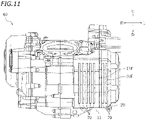
- cooling fins 70 may be provided on the front wall 11F of the crank case 11 and/or the front wall 20F of the crank case cover 20 as shown in FIG. 11 .
- the cooling fins 70 extend forward.
- the cooling fins 70 may extend upward and downward, or may extend leftward and rightward.
- the guide rib 65 may be absent as long as oil, which has flown over the oil tank 33 through the oil return hole 63, is collected into the oil pan 25.
- the first rib portion 65a of the guide rib 65 may be absent.
- the second rib portion 65b of the guide rib 65 may be absent.
- the position of the lower end 65d of the guide rib 65 may be at or above the lower end of the crank web 18A when the crank web 18A has moved to the most downward position.
- the position of the lower end 65d of the guide rib 65 may be at or below the upper end of the inlet 45i of the intake path 45.
- the rear end of the guide rib 65 may be located forward relative to the front end 25f of the oil pan 25.
- the position of the oil return hole 63 may be at or below the axis 18c of the crank shaft 18.
- the position of the oil return hole 63 may be at or below the lower end of the upper edge 23U of the partition side wall 23.
- the oil tank 33 does not need to be arranged next to the generator 19. There is no particular limitation on the position of the oil tank 33.
- the auxiliary tank 34 may be absent.
- the discharge path 46, through which oil discharged from the scavenge pump 40 flows, may be connected directly to the oil tank 33.
- the oil tank inlet 33i does not need to be formed upward of the partition side wall 23.
- the partition side wall 23 may extend upward to the upper wall 11U of the crank case 11 or the upper wall 20U of the crank case cover 20.
- the oil tank inlet 33i may run through the partition side wall 23 at a position downward relative to the upper end of the partition side wall 23.
- the flow path cross-sectional area A34 of the auxiliary tank 34 does not need to increase gradually in the upward direction.
- the flow path cross-sectional area A34 of the auxiliary tank 34 does not need to increase gradually toward the oil tank inlet 33i.
- the first side wall 21, the second side wall 22 and the partition side wall 23 do not need to extend perpendicular to the axis 18c of the crank shaft 18.
- a straddled vehicle refers to a vehicle that is straddled by the rider.
- the straddled vehicle is not limited to the motorcycle 1.
- the straddled vehicle may be an auto tricycle, an ATV (All Terrain Vehicle), or a snowmobile, for example.
Landscapes
- Engineering & Computer Science (AREA)
- Mechanical Engineering (AREA)
- General Engineering & Computer Science (AREA)
- Lubrication Details And Ventilation Of Internal Combustion Engines (AREA)
- Lubrication Of Internal Combustion Engines (AREA)
Abstract
Description
- The present invention relates to an internal combustion engine and a straddled vehicle using dry-sump lubrication.
- As disclosed in
JP H4-298618 A - When the amount of oil in the oil pan increases, the crank web of the crank shaft is immersed in oil, thereby increasing the rotational friction of the crank shaft. In order to prevent the amount of oil in the oil pan from becoming excessive, the pump volume of the scavenge pump is normally set to be larger than the pump volume of the feed pump. The capacity of the scavenge pump is normally set to be larger than the capacity of the feed pump.
- Oil to be transferred from the scavenge pump is stored in the oil tank. When the oil tank becomes full, the load on the scavenge pump becomes high. In order to prevent a large load on the scavenge pump, the oil tank is formed to be larger and is set so as not to become full.
- However, if the oil tank is formed to be larger, it leads to an increase in the size of the internal combustion engine.
- It is an object of the present invention to provide an internal combustion engine that can make oil tanks smaller for internal combustion engines using dry-sump lubrication. According to the present invention said object is solved by an internal combustion engine having the features of
independent claim 1. Preferred embodiments are laid down in the dependent claims. - An internal combustion engine disclosed herein includes: a case; a crank shaft rotatably supported on the case; a first side wall arranged inside the case to partition the inside of the case into a first chamber and a second chamber; an oil pan provided on a bottom portion of the first chamber to store oil therein; an oil tank formed in the second chamber; a scavenge pump having a first intake port that communicates with the oil pan and a discharge port that communicates with the oil tank; and a feed pump having a second intake port that communicates with the oil tank. An oil return hole that connects together the oil tank and the first chamber is formed in an upper portion of the first side wall.
- With the internal combustion engine described above, if the amount of oil stored in the oil tank increases, oil flows over through oil return hole into the first chamber to return to the oil pan. Without making the oil tank larger, it is possible to prevent the oil tank from becoming full. Without making the oil tank larger, it is possible to prevent a large load on the scavenge pump. Therefore, the oil tank can be made smaller.
- The internal combustion engine may include a guide rib protruding from the first side wall toward the first chamber. The guide rib may be formed so as to guide oil, which flows into the first chamber from the oil tank through the oil return hole, into the oil pan.
- Thus, it is possible to smoothly guide oil, which has flown over the oil tank, into the oil pan.
- The guide rib may include a first rib portion arranged upward relative to a lower end of the oil return hole, and a second rib portion arranged at or below a lower end of the oil return hole. The first rib portion and the second rib portion may extend downward.
- Thus, with the first rib portion and the second rib portion, it is possible to suppress scattering of oil, which has flown into the first chamber through the oil return hole. It is possible to smoothly guide oil from the oil return hole into the oil pan.
- The case and the guide rib may together define an oil path that connects together the oil return hole and the oil pan.
- Thus, oil, which has flown into the first chamber through the oil return hole, is guided into the oil pan through the oil path defined.
- The internal combustion engine may include an intake path that has an inlet facing the oil pan and communicates with the first intake port of the scavenge pump. The crank shaft may include a crank web. A lower end of the guide rib may be located downward relative to the crank web and upward relative to the inlet of the intake path.
- Thus, with the guide rib, it is possible to suppress fluctuation of the oil surface of the oil pan. Moreover, with the guide rib, it is possible to preferably supply oil to the inlet of the intake path. Thus, the scavenge pump can stably suck in oil.
- Where an axis direction of the crank shaft is assumed to be a left-right direction and a horizontal direction perpendicular to the axis direction of the crank shaft is assumed to be a front-rear direction, the oil return hole may be located forward relative to an axis of the crank shaft. The guide rib may include a portion located forward relative to a front end of the oil pan and a portion located rearward relative to the front end of the oil pan.
- Thus, with the guide rib, it is possible to preferably suppress fluctuation of the oil surface of the oil pan.
- There is no particular limitation on the position of the oil return hole in the up-down direction. The oil return hole may be located upward relative to an axis of the crank shaft.
- The internal combustion engine may include a generator connected to an end portion of the crank shaft. The case may have an arc-shaped vertical wall located outward in a radial direction of the generator as viewed from an axis direction of the crank shaft. The vertical wall may partition a portion of the oil tank.
- Thus, the oil tank is arranged next to the generator.
- The case may include a crank case that rotatably supports the crank shaft. The first side wall may be provided in the crank case. The case may include a crank case cover having a second side wall arranged sideward of the first side wall. The internal combustion engine may include a partition side wall arranged between the first side wall of the crank case and the second side wall of the crank case cover. The oil tank may be formed between the first side wall and the partition side wall. An auxiliary tank may be formed between the second side wall and the partition side wall. An oil tank inlet that connects together the auxiliary tank and the oil tank may be formed between the first side wall and the second side wall. The discharge port of the scavenge pump may communicate with the oil tank via the auxiliary tank.
- Thus, as the discharge port of the scavenge pump communicates with the oil tank via the auxiliary tank, the flow velocity of oil transferred from the scavenge pump decreases in the auxiliary tank. This suppresses a rapid flow of oil into the oil tank. Gas-liquid separation is performed in the auxiliary tank. Therefore, it is possible to suppress mixing of bubbles in oil in the oil tank. The feed pump can more stably supply oil from the oil tank.
- The oil tank inlet may be formed upward of the partition side wall.
- Thus, oil flows from the auxiliary tank into the oil tank by coming over the partition wall.
- The oil return hole may be formed upward relative to a lower end of an upper edge of the partition side wall.
- The auxiliary tank may be formed so that a flow path cross-sectional area of the auxiliary tank increases gradually in an upward direction.
- Thus, in the auxiliary tank, the flow velocity of oil decreases gradually in the upward direction. This suppresses a rapid flow of oil into the oil tank.
- The first side wall, the second side wall and the partition side wall may be perpendicular to an axis of the crank shaft.
- A straddled vehicle disclosed herein includes the internal combustion engine.
- According to the present invention, it is possible to make oil tanks smaller for internal combustion engines using dry-sump lubrication.
-
-
FIG. 1 is a right side view of a motorcycle according to one embodiment. -
FIG. 2 is a front view of an internal combustion engine. -
FIG. 3 is a left side view of a crank case and a crank case cover. -
FIG. 4 is a left side view of the crank case. -
FIG. 5 is a left side view of a gasket and the crank case. -
FIG. 6 is a partial enlarged perspective view showing the inside of the internal combustion engine, with the crank case cover partially removed. -
FIG. 7 is a cross-sectional view showing an internal configuration of the internal combustion engine as viewed from the right side. -
FIG. 8 is an oil circulation circuit diagram. -
FIG. 9 is a horizontal cross-sectional view showing an example of a configuration of a guide rib. -
FIG. 10 is a horizontal cross-sectional view showing an example of another configuration of a guide rib. -
FIG. 11 is a front view of a crank case and a crank case cover having cooling fins. - An embodiment will now be described with reference to the drawings.
FIG. 1 is a right side view of amotorcycle 1, which is an example of a straddled vehicle. Themotorcycle 1 includes a vehicle body frame 2, an internal combustion engine (hereinafter referred to as an engine) 10 supported on the vehicle body frame 2, a rear wheel 4 driven by theengine 10, afront wheel 5, afuel tank 6, and aseat 7 in which the rider sits. - The terms front, rear, left, right, up and down, as used in the description below, refer to these directions as viewed from a virtual rider seated on a
seat 7 while themotorcycle 1 is standing upright on a horizontal surface with no rider and no load thereon, unless specified otherwise. The designations F, Re, L, R, U and D, as used in the figures, refer to front, rear, left, right, up and down, respectively. The term "forward" refers not only to the direction that extends in the front direction along the vehicle center line, as the vehicle is viewed from above, but also to directions that are inclined from that direction by an angle that is less than 90 degrees in the vehicle left-right direction. Similarly, the term "rearward" refers not only to the direction that extends rearward along the vehicle center line, as the vehicle is viewed from above, but also to directions that are inclined from that direction by an angle that is less than 90 degrees in the vehicle left-right direction. The vehicle front-rear direction F-Re extends along the vehicle center line as the vehicle is viewed from above or viewed from the side. The term "leftward" refers not only to the direction that extends leftward vertical to the vehicle center line, as the vehicle is viewed from above, but also to directions that are inclined from that direction by an angle that is less than 90 degrees in the vehicle front-rear direction. The term "rightward" refers not only to the direction that extends rightward vertical to the vehicle center line, as the vehicle is viewed from above, but also to directions that are inclined from that direction by an angle that is less than 90 degrees in the vehicle front-rear direction. The vehicle left-right direction L-R extends in the vehicle width direction as the vehicle is viewed from above or viewed from the front or the rear and relates to the view direction of a rider sitting on the seat of the vehicle. The term "upward" refers not only to the vertically upward direction, as the vehicle is viewed from the side, but also to directions that are inclined from that direction by an angle that is less than 90 degrees in the vehicle front-rear direction. The term "downward" refers not only to the vertically downward direction, as the vehicle is viewed from the side, but also to directions that are inclined from that direction by an angle that is less than 90 degrees in the vehicle front-rear direction. The vehicle up-down direction U-D extends in the vertical direction of the vehicle as the vehicle is viewed from the side or viewed from the front or the rear. -
FIG. 2 is a front view of theengine 10. Theengine 10 includes a crankcase 11, acylinder body 12 connected to the crankcase 11, acylinder head 13 connected to thecylinder body 12, and acylinder head cover 14 connected to thecylinder head 13. Thecylinder body 12 extends upward from thecrank case 11. Thecylinder head 13 extends upward from thecylinder body 12. Theengine 10 includes a crank case cover 20 connected to the crankcase 11. The crankcase 11 and the crank case cover 20 together form acase 80. The crank case cover 20 is arranged sideward of thecrank case 11. Here, the crank case cover 20 is arranged leftward of thecrank case 11. - An intake port (not shown) and an
exhaust port 15 are formed on thecylinder head 13. Anexhaust pipe 16 is connected to theexhaust port 15. Asilencer 17 is connected to a rear end portion of theexhaust pipe 16. -
FIG. 3 is a left side view of thecrank case 11 and the crank case cover 20 of theengine 10.FIG. 4 is a left side view of thecrank case 11. Agasket 24 is sandwiched between thecrank case 11 and thecrank case cover 20.FIG. 5 is a left side view of thegasket 24 and the crankcase 11.FIG. 6 is a partial enlarged perspective view showing the inside of theengine 10, with the crank case cover 20 partially removed. - As shown in
FIG. 6 , theengine 10 includes thecrank shaft 18. Thecrank shaft 18 is rotatably supported on thecrank case 11. Thecrank shaft 18 extends leftward and rightward. Astraight line 18c represents the axis of thecrank shaft 18. As shown inFIG. 7 , thecrank shaft 18 includes acrank web 18A. - A
generator 19 is connected to an end portion of thecrank shaft 18. Thegenerator 19 is connected to the left end portion of thecrank shaft 18. As viewed from the axis direction of thecrank shaft 18, thegenerator 19 is formed in a generally circular shape. - As shown in
FIG. 4 , thecrank case 11 has afirst side wall 21. Thefirst side wall 21 is a wall that is perpendicular to anaxis 18c of thecrank shaft 18. Thefirst side wall 21 extends in the up-down direction and the front-rear direction.FIG. 7 is a cross-sectional view showing an internal configuration of theengine 10 as viewed from the right side. Afirst chamber 31 is defined rightward of thefirst side wall 21. As shown inFIG. 4 , asecond chamber 32 is defined leftward of thefirst side wall 21. Thefirst side wall 21 is arranged inside thecrank case 11. Thefirst side wall 21 partitions the inside of thecrank case 11 into thefirst chamber 31 and thesecond chamber 32. - As shown in
FIG. 7 , thecrank case 11 has abottom wall 26. Thebottom wall 26 defines anoil pan 25 that stores lubricating oil (hereinafter referred to as oil). InFIG. 7 , a straight line OL represents an example of the oil surface. For example, the oil surface OL may be the oil surface when themotorcycle 1 is stopped standing upright on a horizontal surface and theengine 10 is stopped. Note however that the height of the oil surface OL varies depending on the amount of oil filled in theengine 10. The height of the oil surface OL varies also depending on the operation status of theengine 10. As used herein, theoil pan 25 refers to a portion of thecrank case 11 that is at or below the horizontal plane passing through the lowermost end of thecrank web 18A. InFIG. 7 , a one-dot-chain line 25L represents the horizontal surface passing through the lowermost end of thecrank web 18A. InFIG. 7 , theoil pan 25 refers to a portion of thecrank case 11 that is at or below the one-dot-chain line 25L. Note that thecrank web 18A is formed in a non-circular shape. The position of the lower end of thecrank web 18A varies depending on the rotational position of thecrank web 18A. The lowermost end of thecrank web 18A refers to the lowest end of the lower end of thecrank web 18A. Theoil pan 25 is depressed downward. Theoil pan 25 is provided on the bottom wall of thefirst chamber 31. - The
engine 10 is an internal combustion engine using dry-sump lubrication. Theengine 10 includes ascavenge pump 40. Thescavenge pump 40 includes anintake port 41 and adischarge port 42. Theintake port 41 communicates with theoil pan 25 via anintake path 45. - The
intake path 45 includes anintake chamber 45A and apassageway 45B. Aninlet 45i is formed on theintake chamber 45A. While there is no particular limitation on the position of theinlet 45i, theinlet 45i is herein formed at the front end of theintake chamber 45A. Theinlet 45i serves as an inlet for theintake path 45. Theinlet 45i has an opening facing toward theoil pan 25. Theinlet 45i communicates between theoil pan 25 and theintake chamber 45A. Thepassageway 45B extends upward. An opening 45Bi that has an opening facing toward theintake chamber 45A is formed at the lower end of thepassageway 45B. - The
scavenge pump 40 transfers oil toward anoil tank 33 to be described later. Thedischarge port 42 of thescavenge pump 40 communicates with theoil tank 33 via adischarge path 46. In the present embodiment, thedischarge path 46 includes apassageway 46A extending downward, and apassageway 46B extending leftward from thepassageway 46A. As shown inFIG. 4 , an outlet 46o of thedischarge path 46 is formed on thefirst side wall 21. The outlet 46o has an opening facing leftward. - As shown in
FIG. 3 , the crank case cover 20 has asecond side wall 22 arranged sideward of thefirst side wall 21. Thesecond side wall 22 is arranged leftward of thefirst side wall 21. As with thefirst side wall 21, thesecond side wall 22 is perpendicular to theaxis 18c of thecrank shaft 18. Thesecond side wall 22 extends in the up-down direction and the front-rear direction. - As shown in
FIG. 5 , thegasket 24 has apartition side wall 23 arranged between thefirst side wall 21 of thecrank case 11 and thesecond side wall 22 of thecrank case cover 20. Thepartition side wall 23 is arranged leftward of thefirst side wall 21. Thepartition side wall 23 is arranged rightward of thesecond side wall 22. As with thefirst side wall 21, thepartition side wall 23 is perpendicular to theaxis 18c of thecrank shaft 18. Thepartition side wall 23 extends in the up-down direction and the front-rear direction. - The
oil tank 33 is defined between thefirst side wall 21 and thepartition side wall 23. As shown inFIG. 4 , thecrank case 11 has afront wall 11F, anupper wall 11U, alower wall 11D and arear wall 11B. Thefront wall 11F, theupper wall 11U, thelower wall 11D and therear wall 11B extend leftward. Anupper end 11 Ft of thefront wall 11F and a front end 11Uf of theupper wall 11U are connected together. A lower end 11Fd of thefront wall 11F and a front end 11Df of thelower wall 11D are connected together. An upper end 11Bt of therear wall 11B and a rear end 11Ub of theupper wall 11U are connected together. A lower end 11Bd of therear wall 11B and a rear end 11Db of thelower wall 11D are connected together. Thefront wall 11F, theupper wall 11U, thelower wall 11D and therear wall 11B are connected into a loop. Theoil tank 33 is defined by thefirst side wall 21, thepartition side wall 23, thefront wall 11F, theupper wall 11U, thelower wall 11D and therear wall 11B. Theoil tank 33 is formed in a front portion of thecrank case 11. Therear wall 11B has an arc-shapedvertical wall 11 Br located outward in the radial direction of thegenerator 19, as viewed from the axis direction of thecrank shaft 18. The vertical wall 11Br defines a part of theoil tank 33. Theoil tank 33 is arranged next to thegenerator 19. - An
auxiliary tank 34 is defined between thesecond side wall 22 and thepartition side wall 23. As shown inFIG. 6 , the crank case cover 20 has afront wall 20F, anupper wall 20U, alower wall 20D and arear wall 20B corresponding to thefront wall 11F, theupper wall 11U, thelower wall 11D and therear wall 11B of thecrank case 11, respectively. Thefront wall 20F, theupper wall 20U, thelower wall 20D and therear wall 20B extend rightward. An upper end 20Ft of thefront wall 20F and a front end 20Uf of theupper wall 20U are connected together. A lower end 20Fd of thefront wall 20F and a front end 20Df of thelower wall 20D are connected together. An upper end 20Bt of therear wall 20B and a rear end 20Ub of theupper wall 20U are connected together. A lower end 20Bd of therear wall 20B and a rear end 20Db of thelower wall 20D are connected together. Thefront wall 20F, theupper wall 20U, thelower wall 20D and therear wall 20B are connected into a loop. Theauxiliary tank 34 is defined by thesecond side wall 22, thepartition side wall 23, thefront wall 20F, theupper wall 20U, thelower wall 20D and therear wall 20B. Theauxiliary tank 34 is formed in a front portion of thecrank case cover 20. Therear wall 20B has an arc-shaped vertical wall 20Br located outward in the radial direction of thegenerator 19, as viewed from the axis direction of thecrank shaft 18. The vertical wall 20Br defines a part of theauxiliary tank 34. Theauxiliary tank 34 is arranged next to thegenerator 19. - As shown in
FIG. 5 , anauxiliary tank inlet 34i is formed on thegasket 24. Theauxiliary tank inlet 34i is a through hole formed in thegasket 24. Theauxiliary tank inlet 34i overlaps with the outlet 46o of the discharge path 46 (seeFIG. 4 ). Theauxiliary tank inlet 34i is connected to the outlet 46o of thedischarge path 46. Here, theauxiliary tank inlet 34i has an opening facing leftward. Theauxiliary tank inlet 34i is formed in a lower portion of theauxiliary tank 34. Theauxiliary tank inlet 34i is formed in a rear portion of theauxiliary tank 34. - As shown in
FIG. 6 , anupper edge 23U of thepartition side wall 23 is located downward relative to theupper wall 11U of thecrank case 11 and theupper wall 20U of thecrank case cover 20. Anoil tank inlet 33i that connects together theauxiliary tank 34 and theoil tank 33 is formed upward of thepartition side wall 23. Oil in theauxiliary tank 34 flows into theoil tank 33 by coming over thepartition side wall 23. The opening area of theoil tank inlet 33i is relatively large. As shown inFIG. 5 , the opening area of theoil tank inlet 33i is larger than the opening area of theauxiliary tank inlet 34i. - The
oil tank inlet 33i is formed upward relative to theauxiliary tank inlet 34i. Oil in theauxiliary tank 34 flows upward toward theoil tank inlet 33i. As shown inFIG. 6 , in the upper half portion of theauxiliary tank 34, the interval in the front-rear direction between thefront wall 20F and therear wall 20B of the crank case cover 20 increases gradually in the upward direction. Theauxiliary tank 34 is formed so that a flow path cross-sectional area A34 increases gradually in the upward direction. Theauxiliary tank 34 is formed so that the flow path cross-sectional area A34 increases gradually toward theoil tank inlet 33i. - As shown in
FIG. 4 , an oil tank outlet 33o is formed on thecrank case 11. The oil tank outlet 33o has an opening facing leftward. The oil tank outlet 33o is formed in a lower portion of theoil tank 33. The oil tank outlet 33o is formed in a rear portion of theoil tank 33. -
FIG. 8 is an oil circulation circuit diagram. Theengine 10 includes afeed pump 50 for supplying oil to slidingparts 49 of theengine 10. Thefeed pump 50 includes anintake port 51 and adischarge port 52. The oil tank outlet 33o is connected to theintake port 51 of thefeed pump 50 via anoil path 47. Thedischarge port 52 of thefeed pump 50 communicates with the slidingparts 49 of theengine 10 via anoil path 48. - As shown in
FIG. 4 , anoil return hole 63 that connects together theoil tank 33 and thefirst chamber 31 is formed in an upper portion of thefirst side wall 21. Note that an upper portion of thefirst side wall 21 refers to a portion of thefirst side wall 21 that is upward relative to the middle position thereof in the up-down direction. Thefirst side wall 21 defines the right side of theoil tank 33. An upper portion of thefirst side wall 21 may be a portion of theoil tank 33 that is upward relative to the middle position thereof in the up-down direction. Theoil return hole 63 may be formed at a position that is within 30% of the dimension in the up-down direction of thefirst side wall 21 from the upper end of thefirst side wall 21, or may be formed at a position that is within 20%. Theoil return hole 63 may be formed at a position that is within 30% of the dimension in the up-down direction of theoil tank 33 from the upper end of theoil tank 33, or may be formed at a position that is within 20%. Theoil return hole 63 is located upward relative to theaxis 18c of thecrank shaft 18. - As shown in
FIG. 5 , in the present embodiment, theoil return hole 63 is formed upward relative to a lower end 33id of theoil tank inlet 33i. Note that the lower end 33id of theoil tank inlet 33i corresponds to the lower end of theupper edge 23U of thepartition side wall 23. Theoil return hole 63 is formed upward relative to the lower end of theupper edge 23U of thepartition side wall 23. Theoil return hole 63 is formed downward relative to an upper end 33it of theoil tank inlet 33i. Note however that there is no particular limitation on the position of theoil return hole 63 relative to the lower end 33id and the upper end 33it of theoil tank inlet 33i. - The
oil return hole 63 serves to return oil that flows over theoil tank 33 back into thefirst chamber 31. As indicated by an arrow B63 inFIG. 7 , oil having flown into thefirst chamber 31 from theoil return hole 63 falls down to be collected in theoil pan 25. - The
first side wall 21 is provided with aguide rib 65 protruding toward thefirst chamber 31. Theguide rib 65 protrudes rightward from thefirst side wall 21. Theguide rib 65 is formed so as to guide oil, which flows into thefirst chamber 31 from theoil return hole 63, into theoil pan 25. Theguide rib 65 includes afirst rib portion 65a arranged upward relative to alower end 63d of theoil return hole 63, and asecond rib portion 65b arranged at or below thelower end 63d of theoil return hole 63. Thefirst rib portion 65a is arranged rearward of theoil return hole 63. Thefirst rib portion 65a and thesecond rib portion 65b extend downward. Thefirst rib portion 65a and thesecond rib portion 65b are connected together. Theguide rib 65 includes athird rib portion 65c extending downward and rearward. Thesecond rib portion 65b and thethird rib portion 65c are connected together. - The
front wall 11F and thelower wall 11D of thecrank case 11 and theguide rib 65 together define anoil path 66 that connects together theoil return hole 63 and theoil pan 25. As schematically shown inFIG. 9 , thecrank case 11 includes anotherside wall 28 located rightward of thefirst side wall 21. Theguide rib 65 may extend from thefirst side wall 21 to theother side wall 28. Theguide rib 65 may be connected to, or in contact with, theother side wall 28. As shown inFIG. 10 , theguide rib 65 may be spaced apart from theother side wall 28. The right end of theguide rib 65 may be located leftward relative to theother side wall 28. - As shown in
FIG. 7 , theoil pan 25 is formed of a portion of thebottom wall 26 of thecrank case 11 that is depressed downward. Afront end 25f of theoil pan 25 is located forward relative to theaxis 18c of thecrank shaft 18. Arear end 25b of theoil pan 25 is located rearward relative to theaxis 18c of thecrank shaft 18. Theoil return hole 63 is formed forward relative to theaxis 18c of thecrank shaft 18. Theguide rib 65 extends from a position forward relative to theaxis 18c of thecrank shaft 18 to a position rearward relative to theaxis 18c of thecrank shaft 18. - The
crank shaft 18 includes thecrank web 18A. Alower end 65d of theguide rib 65 is located downward relative to the crankweb 18A. Note that thecrank web 18A moves following the rotation of thecrank shaft 18. As used herein, "being located downward relative to the crankweb 18A" means being located downward relative to the crankweb 18A having moved to the most downward position. Thelower end 65d of theguide rib 65 is located downward relative to the upper end of theoil pan 25. Thelower end 65d of theguide rib 65 is arranged upward relative to theinlet 45i of theintake path 45. - In the present embodiment, the
lower end 65d of theguide rib 65 coincides with the rear end of theguide rib 65. Thelower end 65d of theguide rib 65 is located rearward relative to thefront end 25f of theoil pan 25. Thelower end 65d of theguide rib 65 is located rearward relative to the foremost end of thecrank web 18A. Thelower end 65d of theguide rib 65 is located forward relative to therear end 25b of theoil pan 25. Thelower end 65d of theguide rib 65 is located forward relative to the rearmost end of thecrank web 18A. Thelower end 65d of theguide rib 65 is located forward relative to theintake chamber 45A. Thelower end 65d of theguide rib 65 is located rearward relative to the middle position between thefront end 25f of theoil pan 25 and theintake chamber 45A for the front-rear direction. - The
engine 10 is configured as described above. Next, oil circulation in theengine 10 will be described. Note that in the following description, upstream side refers to the side from which oil flows. Downstream side refers to the side toward which oil flows. - The
oil pan 25 stores oil therein. As indicated by an arrow inFIG. 8 , oil in theoil pan 25 is sucked into thescavenge pump 40 through theintake path 45. Thescavenge pump 40 transfers oil to theauxiliary tank 34 through thedischarge path 46. Oil, which has been transferred to theauxiliary tank 34, flows upward in theauxiliary tank 34 and flows into theoil tank 33 through theoil tank inlet 33i. - In the present embodiment, oil is not directly transferred from the
discharge path 46 to theoil tank 33. Oil is once transferred to theauxiliary tank 34, and then transferred to theoil tank 33. The flow path cross-sectional area of theauxiliary tank 34 is larger than the flow path cross-sectional area of thedischarge path 46. The flow velocity of oil is relatively high in thedischarge path 46, but it is relatively low in theauxiliary tank 34. Before oil flows into theoil tank 33, the flow velocity of oil decreases. Therefore, oil slowly flows into theoil tank 33 from theauxiliary tank 34. This suppresses a rapid flow of oil into theoil tank 33. This suppresses mixing of bubbles in oil in theoil tank 33. - The
auxiliary tank 34 has a gas-liquid separation function. Even if bubbles are mixed in the oil transferred from thedischarge path 46, oil and air are separated from each other in theauxiliary tank 34. Oil, from which air has been separated, flows into theoil tank 33. This suppresses mixing of bubbles in oil in theoil tank 33. - Oil in the
oil tank 33 is sucked into thefeed pump 50 through theoil path 47. Thefeed pump 50 supplies oil to the slidingparts 49 of theengine 10 through theoil path 48. After lubricating the slidingparts 49, oil returns to theoil pan 25 to be stored in theoil pan 25. - Now, if the
oil tank 33 becomes full, the internal pressure of theoil tank 33 increases. In that case, there is a high load on thescavenge pump 40. According to the present embodiment, however, theoil return hole 63 is formed in theoil tank 33. When the amount of oil transferred to theoil tank 33 temporarily becomes large, oil in theoil tank 33 flows out through theoil return hole 63. Therefore, it is possible to avoid theoil tank 33 becoming full. This suppresses the load on thescavenge pump 40 from becoming high. - As shown in
FIG. 7 , oil, which has flown into thefirst chamber 31 from theoil tank 33 through theoil return hole 63, is guided to theoil pan 25 by theguide rib 65. This suppresses scattering of oil, which has flown over theoil tank 33, in thefirst chamber 31. Oil, which has flown over theoil tank 33, is smoothly guided into theoil pan 25. - Next, various advantageous effects realized by the
engine 10 according to the present embodiment will be described. - As described above, with the
engine 10 according to the present embodiment, theoil return hole 63 is formed in an upper portion of thefirst side wall 21. If the amount of oil to be transferred from thescavenge pump 40 to theoil tank 33 increases temporarily, oil flows out from theoil tank 33 through theoil return hole 63. Therefore, there is no need to make theoil tank 33 larger in advance so as to avoid theoil tank 33 becoming full. According to the present embodiment, without making theoil tank 33 larger, it is possible to prevent a large load on thescavenge pump 40. Therefore, it is possible to make theoil tank 33 smaller. - As shown in
FIG. 7 , according to the present embodiment, theguide rib 65 is provided for guiding oil, which flows into thefirst chamber 31 through theoil return hole 63, into theoil pan 25. Therefore, oil flowing over theoil tank 33 can be smoothly guided into theoil pan 25. - According to the present embodiment, the
guide rib 65 includes thefirst rib portion 65a arranged upward relative to thelower end 63d of theoil return hole 63, and thesecond rib portion 65b arranged at or below thelower end 63d of theoil return hole 63. Thefirst rib portion 65a and thesecond rib portion 65b extend downward. With thefirst rib portion 65a and thesecond rib portion 65b, it is possible to suppress scattering of oil, which has flown into thefirst chamber 31 through theoil return hole 63. Therefore, it is possible to smoothly guide oil from theoil return hole 63 into theoil pan 25. - According to the present embodiment, the
front wall 11F and thelower wall 11D of thecrank case 11 and theguide rib 65 together define theoil path 66 that connects together theoil return hole 63 and theoil pan 25. With theoil path 66, it is possible to smoothly guide oil from theoil return hole 63 into theoil pan 25. - According to the present embodiment, the
guide rib 65 extends to a relatively low position. Thelower end 65d of theguide rib 65 is located downward relative to the crankweb 18A and upward relative to theinlet 45i of theintake path 45. Since thelower end 65d is located at a relatively low position, it is possible to suppress fluctuation of the oil surface by theguide rib 65. It is possible to suppress fluctuation of the oil surface, irrespective of fluctuation of pressure caused by the piston (not shown) of theengine 10 moving up and down. When themotorcycle 1 decelerates, oil in theoil pan 25 tends to move forward due to an inertial force. According to the present embodiment, upon sudden braking of themotorcycle 1, oil may possibly move temporarily forward from theoil pan 25, but that oil flows into theoil path 66. Thus, oil is unlikely to scatter upon sudden braking of themotorcycle 1. After sudden braking of themotorcycle 1, oil quickly returns from theoil path 66 into theoil pan 25. Since thelower end 65d of theguide rib 65 is located upward relative to theinlet 45i of theintake path 45, oil can be quickly supplied from theoil path 66 to theinlet 45i after sudden braking. - According to the present embodiment, the
guide rib 65 extends from a position forward relative to thefront end 25f of theoil pan 25 to a position rearward relative to thefront end 25f of theoil pan 25. The rear end of the guide rib 65 (in the present embodiment, the rear end of theguide rib 65 coincides with thelower end 65d) is located rearward relative to thefront end 25f of theoil pan 25. Theguide rib 65 comes into contact with oil in theoil pan 25. Therefore, with theguide rib 65, it is possible to suppress fluctuation of the oil surface of theoil pan 25. - Although there is no particular limitation on the position of the
oil return hole 63, it is preferably a relatively high position. In the present embodiment, theoil return hole 63 is located upward relative to theaxis 18c of thecrank shaft 18. Theoil return hole 63 is located upward relative to the lower end of theupper edge 23U of thepartition side wall 23. By forming theoil return hole 63 at a relatively high position, it is possible to ensure a sufficient storing volume of theoil tank 33. - If oil rapidly flows into the
oil tank 33, bubbles may be mixed in oil flowing into theoil tank 33. According to the present embodiment, however, theauxiliary tank 34 is provided upstream of theoil tank 33. The flow velocity of oil decreases in theauxiliary tank 34. This suppresses a rapid flow of oil into theoil tank 33. Gas-liquid separation is performed in theauxiliary tank 34. Therefore, it is possible to suppress mixing of bubbles in oil in theoil tank 33. It is possible to more stably supply oil to the slidingparts 49 from thefeed pump 50. - According to the present embodiment, the
auxiliary tank 34 is formed so that the flow path cross-sectional area A34 of theauxiliary tank 34 increases gradually in the upward direction. Theauxiliary tank 34 is formed so that the flow path cross-sectional area A34 of theauxiliary tank 34 increases gradually toward theoil tank inlet 33i. Therefore, the flow velocity of oil decreases gradually in the upward direction. The flow velocity of oil decreases gradually toward theoil tank inlet 33i. This further suppresses a rapid flow of oil into theoil tank 33. It is possible to further suppress mixing of bubbles in oil in theoil tank 33. - According to the present embodiment, the
front wall 11F of thecrank case 11 defines a part of theoil tank 33. Thefront wall 20F of the crank case cover 20 defines a part of theauxiliary tank 34. When themotorcycle 1 runs, wind blows, coming from the front side, thefront wall 11F of thecrank case 11 and thefront wall 20F of thecrank case cover 20. Therefore, oil inside theoil tank 33 and theauxiliary tank 34 can be cooled by the wind generated while running. Moreover, oil being collected into theoil pan 25 from theoil return hole 63 can be cooled. - Note that in order to increase the cooling efficiency, cooling
fins 70 may be provided on thefront wall 11F of thecrank case 11 and/or thefront wall 20F of the crank case cover 20 as shown inFIG. 11 . The coolingfins 70 extend forward. The coolingfins 70 may extend upward and downward, or may extend leftward and rightward. There is no particular limitation on the shape, arrangement and number of the coolingfins 70. By providing the coolingfins 70 as described above, oil inside theoil tank 33 and/or theauxiliary tank 34 can be more efficiently cooled by the wind generated while themotorcycle 1 runs. Moreover, oil being collected into theoil pan 25 from theoil return hole 63 can be cooled more efficiently. - While one embodiment has been described above, the embodiment is merely an example. Various other embodiments are possible.
- The
guide rib 65 may be absent as long as oil, which has flown over theoil tank 33 through theoil return hole 63, is collected into theoil pan 25. - The
first rib portion 65a of theguide rib 65 may be absent. Thesecond rib portion 65b of theguide rib 65 may be absent. - There is no particular limitation on the position of the
lower end 65d of theguide rib 65. The position of thelower end 65d of theguide rib 65 may be at or above the lower end of thecrank web 18A when thecrank web 18A has moved to the most downward position. The position of thelower end 65d of theguide rib 65 may be at or below the upper end of theinlet 45i of theintake path 45. - There is no particular limitation on the size in the up-down direction and the size in the front-rear direction of the
guide rib 65. The rear end of theguide rib 65 may be located forward relative to thefront end 25f of theoil pan 25. - The position of the
oil return hole 63 may be at or below theaxis 18c of thecrank shaft 18. The position of theoil return hole 63 may be at or below the lower end of theupper edge 23U of thepartition side wall 23. - The
oil tank 33 does not need to be arranged next to thegenerator 19. There is no particular limitation on the position of theoil tank 33. - The
auxiliary tank 34 may be absent. Thedischarge path 46, through which oil discharged from thescavenge pump 40 flows, may be connected directly to theoil tank 33. - The
oil tank inlet 33i does not need to be formed upward of thepartition side wall 23. Thepartition side wall 23 may extend upward to theupper wall 11U of thecrank case 11 or theupper wall 20U of thecrank case cover 20. Theoil tank inlet 33i may run through thepartition side wall 23 at a position downward relative to the upper end of thepartition side wall 23. - The flow path cross-sectional area A34 of the
auxiliary tank 34 does not need to increase gradually in the upward direction. The flow path cross-sectional area A34 of theauxiliary tank 34 does not need to increase gradually toward theoil tank inlet 33i. - The
first side wall 21, thesecond side wall 22 and thepartition side wall 23 do not need to extend perpendicular to theaxis 18c of thecrank shaft 18. - A straddled vehicle refers to a vehicle that is straddled by the rider. The straddled vehicle is not limited to the
motorcycle 1. The straddled vehicle may be an auto tricycle, an ATV (All Terrain Vehicle), or a snowmobile, for example. - 1: Motorcycle (straddled vehicle), 10: Internal combustion engine, 11: Crank case, 11Br: Vertical wall, 18: Crank shaft, 18A: Crank web, 18c: Axis of crank shaft, 19: Generator, 20: Crank case cover, 21: First side wall, 22: Second side wall, 23: Partition side wall, 25: Oil pan, 31: First chamber, 32: Second chamber, 33: Oil tank, 33i: Oil tank inlet, 34: Auxiliary tank, 40: Scavenge pump, 41: Intake port (first intake port), 42: Discharge port, 45: Intake path, 45i: Inlet, 50: Feed pump, 51: Intake port (second intake port), 60: Case, 63: Oil return hole, 65: Guide rib, 65a: First rib portion, 65b: Second rib portion, 66: Oil path
Claims (14)
- An internal combustion engine (10) configured to be arranged within a straddled vehicle, the internal combustion engine (10) comprising:a case (60);a crank shaft (18) rotatably supported on the case (60);a first side wall (21) arranged inside the case (60) to partition the inside of the case (60) into a first chamber (31) and a second chamber (32);an oil pan (25) provided on a bottom portion of the first chamber (31) to store oil therein;an oil tank (33) formed in the second chamber (32);a scavenge pump (40) having a first intake port (41) that communicates with the oil pan (25) and a discharge port (42) that communicates with the oil tank (33); anda feed pump (50) having a second intake port (51) that communicates with the oil tank (33),wherein an oil return hole (63) that connects together the oil tank (33) and the first chamber (31) is formed in an upper portion of the first side wall (21) with regard to an vehicle up-down direction (U-D).
- The internal combustion engine (10) according to claim 1, wherein:the internal combustion engine (10) includes a guide rib (65) protruding from the first side wall (21) toward the first chamber (31); andthe guide rib (65) is formed so as to guide oil, which flows into the first chamber (31) from the oil tank (33) through the oil return hole (63), into the oil pan (25).
- The internal combustion engine (10) according to claim 2, wherein:the guide rib (65) includes a first rib portion (65a) arranged upward relative to a lower end (63d) of the oil return hole (63) with regard to the vehicle up-down direction (U-D),and a second rib portion (65b) arranged at or below a lower end (63d) of the oil return hole (63) with regard to the vehicle up-down direction (U-D); andthe first rib portion (65a) and the second rib portion (65b) extend downward with regard to the vehicle up-down direction (U-D).
- The internal combustion engine (10) according to claim 2 or 3, wherein the case (60) and the guide rib (65) together define an oil path (66) that connects together the oil return hole (63) and the oil pan (25).
- The internal combustion engine (10) according to any one of claims 2 to 4, wherein:the internal combustion engine (10) includes an intake path (45) that has an inlet (45i) facing the oil pan (25) and communicates with the first intake port (41) of the scavenge pump (40);the crank shaft (18) includes a crank web (18A); anda lower end (65d) of the guide rib (65) is located downward relative to the crank web (18A) and upward relative to the inlet (45i) of the intake path (45) with regard to the vehicle up-down direction (U-D).
- The internal combustion engine (10) according to any one of claims 2 to 5, wherein:where an axis direction of the crank shaft (18) is assumed to be a left-right direction with regard to a vehicle left-right direction (L-R) and a horizontal direction perpendicular to the axis direction of the crank shaft (18) is assumed to be a front-rear direction with regard to a vehicle front-rear direction (F-Re),the oil return hole (63) is located forward relative to an axis (18c) of the crank shaft (18) with regard to the front-rear direction; andthe guide rib (65) includes a portion located forward relative to a front end (25f) of the oil pan (25) and a portion located rearward relative to the front end (25f) of the oil pan (25) with regard to the front-rear direction.
- The internal combustion engine (10) according to any one of claims 1 to 6, wherein the oil return hole (63) is located upward relative to an axis (18c) of the crank shaft (18) with regard to the vehicle up-down direction (U-D).
- The internal combustion engine (10) according to claim 7, wherein:the internal combustion engine (10) includes a generator (19) connected to an end portion of the crank shaft (18);the case (60) has an arc-shaped vertical wall (11Br) located outward in a radial direction of the generator (19) as viewed from an axis direction of the crank shaft (18);andthe vertical wall (11Br) partitions a portion of the oil tank (33).
- The internal combustion engine (10) according to claim 7 or 8, wherein:the case (60) includes a crank case (11) that rotatably supports the crank shaft (18);the first side wall (21) is provided in the crank case (11);the case (60) includes a crank case cover (20) having a second side wall (22) arranged sideward of the first side wall (21) with regard to a vehicle left-right direction (L-R);the internal combustion engine (10) includes a partition side wall (23) arranged between the first side wall (21) of the crank case (11) and the second side wall (22) of the crank case cover (20);the oil tank (33) is formed between the first side wall (21) and the partition side wall (23);an auxiliary tank (34) is formed between the second side wall (22) and the partition side wall (23);an oil tank inlet (33i) that connects together the auxiliary tank (34) and the oil tank (33) is formed between the first side wall (21) and the second side wall (22); andthe discharge port (42) of the scavenge pump (40) communicates with the oil tank (33) via the auxiliary tank (34).
- The internal combustion engine (10) according to claim 9, wherein the oil tank inlet (33i) is formed upward of the partition side wall (23) with regard to the vehicle up-down direction (U-D).
- The internal combustion engine (10) according to claim 9 or 10, wherein the oil return hole (63) is formed upward relative to a lower end of an upper edge (23U) of the partition side wall (23) with regard to the vehicle up-down direction (U-D).
- The internal combustion engine (10) according to any one of claims 9 to 11, wherein the auxiliary tank (34) is formed so that a flow path cross-sectional area (A34) of the auxiliary tank (34) increases gradually in an upward direction with regard to the vehicle up-down direction (U-D).
- The internal combustion engine (10) according to any one of claims 9 to 12, wherein the first side wall (21), the second side wall (22) and the partition side wall (23) are perpendicular to an axis (18c) of the crank shaft (18).
- A straddled vehicle (1) comprising an internal combustion engine (10) according to any one of claims 1 to 13.
Applications Claiming Priority (1)
| Application Number | Priority Date | Filing Date | Title |
|---|---|---|---|
| JP2021073043A JP2022167315A (en) | 2021-04-23 | 2021-04-23 | Internal combustion engine and saddle-riding type vehicle |
Publications (2)
| Publication Number | Publication Date |
|---|---|
| EP4080020A1 true EP4080020A1 (en) | 2022-10-26 |
| EP4080020B1 EP4080020B1 (en) | 2024-02-14 |
Family
ID=78828191
Family Applications (1)
| Application Number | Title | Priority Date | Filing Date |
|---|---|---|---|
| EP21213407.6A Active EP4080020B1 (en) | 2021-04-23 | 2021-12-09 | Internal combustion engine and straddled vehicle |
Country Status (2)
| Country | Link |
|---|---|
| EP (1) | EP4080020B1 (en) |
| JP (1) | JP2022167315A (en) |
Citations (5)
| Publication number | Priority date | Publication date | Assignee | Title |
|---|---|---|---|---|
| JPH04298618A (en) | 1991-03-27 | 1992-10-22 | Honda Motor Co Ltd | Oil tank structure of dry sump lubricated internal combustion engine |
| US6318333B1 (en) * | 1999-09-03 | 2001-11-20 | Honda Giken Kogyo Kabushiki Kaisha | Accessory arrangement structure for internal combustion engine |
| US20020003064A1 (en) * | 2000-05-11 | 2002-01-10 | Katsuhiko Ito | Lubricating system for internal combustion engine |
| US20040108166A1 (en) * | 2002-09-18 | 2004-06-10 | Katsuhiko Ito | Lubricating system for internal combustion engine |
| US20130333980A1 (en) * | 2012-06-14 | 2013-12-19 | Honda Motor Co., Ltd | Lubricating device for power unit |
-
2021
- 2021-04-23 JP JP2021073043A patent/JP2022167315A/en active Pending
- 2021-12-09 EP EP21213407.6A patent/EP4080020B1/en active Active
Patent Citations (5)
| Publication number | Priority date | Publication date | Assignee | Title |
|---|---|---|---|---|
| JPH04298618A (en) | 1991-03-27 | 1992-10-22 | Honda Motor Co Ltd | Oil tank structure of dry sump lubricated internal combustion engine |
| US6318333B1 (en) * | 1999-09-03 | 2001-11-20 | Honda Giken Kogyo Kabushiki Kaisha | Accessory arrangement structure for internal combustion engine |
| US20020003064A1 (en) * | 2000-05-11 | 2002-01-10 | Katsuhiko Ito | Lubricating system for internal combustion engine |
| US20040108166A1 (en) * | 2002-09-18 | 2004-06-10 | Katsuhiko Ito | Lubricating system for internal combustion engine |
| US20130333980A1 (en) * | 2012-06-14 | 2013-12-19 | Honda Motor Co., Ltd | Lubricating device for power unit |
Also Published As
| Publication number | Publication date |
|---|---|
| EP4080020B1 (en) | 2024-02-14 |
| JP2022167315A (en) | 2022-11-04 |
Similar Documents
| Publication | Publication Date | Title |
|---|---|---|
| US6527087B2 (en) | Lubricating system for internal combustion engine | |
| EP1258424B1 (en) | Vehicle, especially snowmobile, with an engine and and oil tank | |
| CN102865123B (en) | Ventilation structure of engine for motorcycle | |
| EP4080021B1 (en) | Internal combustion engine and straddled vehicle | |
| CA3067563C (en) | Straddled vehicle | |
| US7717233B2 (en) | Oil tank for engine-driven vehicle | |
| EP4080020B1 (en) | Internal combustion engine and straddled vehicle | |
| EP1959168A2 (en) | Vehicle | |
| JP2024004965A (en) | Internal combustion engines and saddle-type vehicles | |
| EP3321480B1 (en) | Straddled vehicle | |
| EP2295833A1 (en) | Engine unit, and a two-wheeled motor vehicle having the same | |
| CN117027997A (en) | Crankcase ventilation devices and vehicles | |
| JP6642233B2 (en) | Saddle-type vehicle | |
| JPWO2020111188A1 (en) | Saddle-riding vehicle | |
| JP4211778B2 (en) | Motorcycle fuel supply system | |
| JPH1181972A (en) | Dry sump engine | |
| CN100547232C (en) | Crankcase and motorcycle including the crankcase | |
| JP2019052605A (en) | Internal combustion engine | |
| US20190085740A1 (en) | Internal combustion engine | |
| JP2010151084A (en) | Breather structure for engine | |
| JP2007113565A (en) | Breather equipment for motorcycles | |
| JP7518480B2 (en) | engine | |
| EP1655215A1 (en) | Fuel tank of motorcycle and motorcycle | |
| JPH11141400A (en) | Oil storage structure of 4-cycle engine | |
| EP4406819A1 (en) | Straddled vehicle |
Legal Events
| Date | Code | Title | Description |
|---|---|---|---|
| PUAI | Public reference made under article 153(3) epc to a published international application that has entered the european phase |
Free format text: ORIGINAL CODE: 0009012 |
|
| STAA | Information on the status of an ep patent application or granted ep patent |
Free format text: STATUS: THE APPLICATION HAS BEEN PUBLISHED |
|
| AK | Designated contracting states |
Kind code of ref document: A1 Designated state(s): AL AT BE BG CH CY CZ DE DK EE ES FI FR GB GR HR HU IE IS IT LI LT LU LV MC MK MT NL NO PL PT RO RS SE SI SK SM TR |
|
| STAA | Information on the status of an ep patent application or granted ep patent |
Free format text: STATUS: REQUEST FOR EXAMINATION WAS MADE |
|
| 17P | Request for examination filed |
Effective date: 20221102 |
|
| RBV | Designated contracting states (corrected) |
Designated state(s): AL AT BE BG CH CY CZ DE DK EE ES FI FR GB GR HR HU IE IS IT LI LT LU LV MC MK MT NL NO PL PT RO RS SE SI SK SM TR |
|
| P01 | Opt-out of the competence of the unified patent court (upc) registered |
Effective date: 20230527 |
|
| GRAP | Despatch of communication of intention to grant a patent |
Free format text: ORIGINAL CODE: EPIDOSNIGR1 |
|
| STAA | Information on the status of an ep patent application or granted ep patent |
Free format text: STATUS: GRANT OF PATENT IS INTENDED |
|
| INTG | Intention to grant announced |
Effective date: 20231113 |
|
| GRAS | Grant fee paid |
Free format text: ORIGINAL CODE: EPIDOSNIGR3 |
|
| GRAA | (expected) grant |
Free format text: ORIGINAL CODE: 0009210 |
|
| STAA | Information on the status of an ep patent application or granted ep patent |
Free format text: STATUS: THE PATENT HAS BEEN GRANTED |
|
| AK | Designated contracting states |
Kind code of ref document: B1 Designated state(s): AL AT BE BG CH CY CZ DE DK EE ES FI FR GB GR HR HU IE IS IT LI LT LU LV MC MK MT NL NO PL PT RO RS SE SI SK SM TR |
|
| REG | Reference to a national code |
Ref country code: GB Ref legal event code: FG4D |
|
| REG | Reference to a national code |
Ref country code: CH Ref legal event code: EP |
|
| REG | Reference to a national code |
Ref country code: DE Ref legal event code: R096 Ref document number: 602021009367 Country of ref document: DE |
|
| REG | Reference to a national code |
Ref country code: IE Ref legal event code: FG4D |
|
| REG | Reference to a national code |
Ref country code: LT Ref legal event code: MG9D |
|
| REG | Reference to a national code |
Ref country code: NL Ref legal event code: MP Effective date: 20240214 |
|
| PG25 | Lapsed in a contracting state [announced via postgrant information from national office to epo] |
Ref country code: IS Free format text: LAPSE BECAUSE OF FAILURE TO SUBMIT A TRANSLATION OF THE DESCRIPTION OR TO PAY THE FEE WITHIN THE PRESCRIBED TIME-LIMIT Effective date: 20240614 |
|
| PG25 | Lapsed in a contracting state [announced via postgrant information from national office to epo] |
Ref country code: LT Free format text: LAPSE BECAUSE OF FAILURE TO SUBMIT A TRANSLATION OF THE DESCRIPTION OR TO PAY THE FEE WITHIN THE PRESCRIBED TIME-LIMIT Effective date: 20240214 |
|
| PG25 | Lapsed in a contracting state [announced via postgrant information from national office to epo] |
Ref country code: GR Free format text: LAPSE BECAUSE OF FAILURE TO SUBMIT A TRANSLATION OF THE DESCRIPTION OR TO PAY THE FEE WITHIN THE PRESCRIBED TIME-LIMIT Effective date: 20240515 |
|
| REG | Reference to a national code |
Ref country code: AT Ref legal event code: MK05 Ref document number: 1657171 Country of ref document: AT Kind code of ref document: T Effective date: 20240214 |
|
| PG25 | Lapsed in a contracting state [announced via postgrant information from national office to epo] |
Ref country code: HR Free format text: LAPSE BECAUSE OF FAILURE TO SUBMIT A TRANSLATION OF THE DESCRIPTION OR TO PAY THE FEE WITHIN THE PRESCRIBED TIME-LIMIT Effective date: 20240214 Ref country code: RS Free format text: LAPSE BECAUSE OF FAILURE TO SUBMIT A TRANSLATION OF THE DESCRIPTION OR TO PAY THE FEE WITHIN THE PRESCRIBED TIME-LIMIT Effective date: 20240514 Ref country code: NL Free format text: LAPSE BECAUSE OF FAILURE TO SUBMIT A TRANSLATION OF THE DESCRIPTION OR TO PAY THE FEE WITHIN THE PRESCRIBED TIME-LIMIT Effective date: 20240214 |
|
| PG25 | Lapsed in a contracting state [announced via postgrant information from national office to epo] |
Ref country code: ES Free format text: LAPSE BECAUSE OF FAILURE TO SUBMIT A TRANSLATION OF THE DESCRIPTION OR TO PAY THE FEE WITHIN THE PRESCRIBED TIME-LIMIT Effective date: 20240214 |
|
| PG25 | Lapsed in a contracting state [announced via postgrant information from national office to epo] |
Ref country code: AT Free format text: LAPSE BECAUSE OF FAILURE TO SUBMIT A TRANSLATION OF THE DESCRIPTION OR TO PAY THE FEE WITHIN THE PRESCRIBED TIME-LIMIT Effective date: 20240214 |
|
| PG25 | Lapsed in a contracting state [announced via postgrant information from national office to epo] |
Ref country code: RS Free format text: LAPSE BECAUSE OF FAILURE TO SUBMIT A TRANSLATION OF THE DESCRIPTION OR TO PAY THE FEE WITHIN THE PRESCRIBED TIME-LIMIT Effective date: 20240514 Ref country code: NO Free format text: LAPSE BECAUSE OF FAILURE TO SUBMIT A TRANSLATION OF THE DESCRIPTION OR TO PAY THE FEE WITHIN THE PRESCRIBED TIME-LIMIT Effective date: 20240514 Ref country code: NL Free format text: LAPSE BECAUSE OF FAILURE TO SUBMIT A TRANSLATION OF THE DESCRIPTION OR TO PAY THE FEE WITHIN THE PRESCRIBED TIME-LIMIT Effective date: 20240214 Ref country code: LT Free format text: LAPSE BECAUSE OF FAILURE TO SUBMIT A TRANSLATION OF THE DESCRIPTION OR TO PAY THE FEE WITHIN THE PRESCRIBED TIME-LIMIT Effective date: 20240214 Ref country code: IS Free format text: LAPSE BECAUSE OF FAILURE TO SUBMIT A TRANSLATION OF THE DESCRIPTION OR TO PAY THE FEE WITHIN THE PRESCRIBED TIME-LIMIT Effective date: 20240614 Ref country code: HR Free format text: LAPSE BECAUSE OF FAILURE TO SUBMIT A TRANSLATION OF THE DESCRIPTION OR TO PAY THE FEE WITHIN THE PRESCRIBED TIME-LIMIT Effective date: 20240214 Ref country code: GR Free format text: LAPSE BECAUSE OF FAILURE TO SUBMIT A TRANSLATION OF THE DESCRIPTION OR TO PAY THE FEE WITHIN THE PRESCRIBED TIME-LIMIT Effective date: 20240515 Ref country code: FI Free format text: LAPSE BECAUSE OF FAILURE TO SUBMIT A TRANSLATION OF THE DESCRIPTION OR TO PAY THE FEE WITHIN THE PRESCRIBED TIME-LIMIT Effective date: 20240214 Ref country code: ES Free format text: LAPSE BECAUSE OF FAILURE TO SUBMIT A TRANSLATION OF THE DESCRIPTION OR TO PAY THE FEE WITHIN THE PRESCRIBED TIME-LIMIT Effective date: 20240214 Ref country code: BG Free format text: LAPSE BECAUSE OF FAILURE TO SUBMIT A TRANSLATION OF THE DESCRIPTION OR TO PAY THE FEE WITHIN THE PRESCRIBED TIME-LIMIT Effective date: 20240214 Ref country code: AT Free format text: LAPSE BECAUSE OF FAILURE TO SUBMIT A TRANSLATION OF THE DESCRIPTION OR TO PAY THE FEE WITHIN THE PRESCRIBED TIME-LIMIT Effective date: 20240214 |
|
| PG25 | Lapsed in a contracting state [announced via postgrant information from national office to epo] |
Ref country code: PL Free format text: LAPSE BECAUSE OF FAILURE TO SUBMIT A TRANSLATION OF THE DESCRIPTION OR TO PAY THE FEE WITHIN THE PRESCRIBED TIME-LIMIT Effective date: 20240214 Ref country code: PT Free format text: LAPSE BECAUSE OF FAILURE TO SUBMIT A TRANSLATION OF THE DESCRIPTION OR TO PAY THE FEE WITHIN THE PRESCRIBED TIME-LIMIT Effective date: 20240614 |
|
| PG25 | Lapsed in a contracting state [announced via postgrant information from national office to epo] |
Ref country code: SE Free format text: LAPSE BECAUSE OF FAILURE TO SUBMIT A TRANSLATION OF THE DESCRIPTION OR TO PAY THE FEE WITHIN THE PRESCRIBED TIME-LIMIT Effective date: 20240214 Ref country code: PT Free format text: LAPSE BECAUSE OF FAILURE TO SUBMIT A TRANSLATION OF THE DESCRIPTION OR TO PAY THE FEE WITHIN THE PRESCRIBED TIME-LIMIT Effective date: 20240614 Ref country code: PL Free format text: LAPSE BECAUSE OF FAILURE TO SUBMIT A TRANSLATION OF THE DESCRIPTION OR TO PAY THE FEE WITHIN THE PRESCRIBED TIME-LIMIT Effective date: 20240214 Ref country code: LV Free format text: LAPSE BECAUSE OF FAILURE TO SUBMIT A TRANSLATION OF THE DESCRIPTION OR TO PAY THE FEE WITHIN THE PRESCRIBED TIME-LIMIT Effective date: 20240214 |
|
| PG25 | Lapsed in a contracting state [announced via postgrant information from national office to epo] |
Ref country code: DK Free format text: LAPSE BECAUSE OF FAILURE TO SUBMIT A TRANSLATION OF THE DESCRIPTION OR TO PAY THE FEE WITHIN THE PRESCRIBED TIME-LIMIT Effective date: 20240214 |
|
| PG25 | Lapsed in a contracting state [announced via postgrant information from national office to epo] |
Ref country code: SM Free format text: LAPSE BECAUSE OF FAILURE TO SUBMIT A TRANSLATION OF THE DESCRIPTION OR TO PAY THE FEE WITHIN THE PRESCRIBED TIME-LIMIT Effective date: 20240214 |
|
| PG25 | Lapsed in a contracting state [announced via postgrant information from national office to epo] |
Ref country code: EE Free format text: LAPSE BECAUSE OF FAILURE TO SUBMIT A TRANSLATION OF THE DESCRIPTION OR TO PAY THE FEE WITHIN THE PRESCRIBED TIME-LIMIT Effective date: 20240214 Ref country code: CZ Free format text: LAPSE BECAUSE OF FAILURE TO SUBMIT A TRANSLATION OF THE DESCRIPTION OR TO PAY THE FEE WITHIN THE PRESCRIBED TIME-LIMIT Effective date: 20240214 |
|
| PG25 | Lapsed in a contracting state [announced via postgrant information from national office to epo] |
Ref country code: SK Free format text: LAPSE BECAUSE OF FAILURE TO SUBMIT A TRANSLATION OF THE DESCRIPTION OR TO PAY THE FEE WITHIN THE PRESCRIBED TIME-LIMIT Effective date: 20240214 |
|
| PG25 | Lapsed in a contracting state [announced via postgrant information from national office to epo] |
Ref country code: SM Free format text: LAPSE BECAUSE OF FAILURE TO SUBMIT A TRANSLATION OF THE DESCRIPTION OR TO PAY THE FEE WITHIN THE PRESCRIBED TIME-LIMIT Effective date: 20240214 Ref country code: SK Free format text: LAPSE BECAUSE OF FAILURE TO SUBMIT A TRANSLATION OF THE DESCRIPTION OR TO PAY THE FEE WITHIN THE PRESCRIBED TIME-LIMIT Effective date: 20240214 Ref country code: RO Free format text: LAPSE BECAUSE OF FAILURE TO SUBMIT A TRANSLATION OF THE DESCRIPTION OR TO PAY THE FEE WITHIN THE PRESCRIBED TIME-LIMIT Effective date: 20240214 Ref country code: EE Free format text: LAPSE BECAUSE OF FAILURE TO SUBMIT A TRANSLATION OF THE DESCRIPTION OR TO PAY THE FEE WITHIN THE PRESCRIBED TIME-LIMIT Effective date: 20240214 Ref country code: DK Free format text: LAPSE BECAUSE OF FAILURE TO SUBMIT A TRANSLATION OF THE DESCRIPTION OR TO PAY THE FEE WITHIN THE PRESCRIBED TIME-LIMIT Effective date: 20240214 Ref country code: CZ Free format text: LAPSE BECAUSE OF FAILURE TO SUBMIT A TRANSLATION OF THE DESCRIPTION OR TO PAY THE FEE WITHIN THE PRESCRIBED TIME-LIMIT Effective date: 20240214 |
|
| REG | Reference to a national code |
Ref country code: DE Ref legal event code: R097 Ref document number: 602021009367 Country of ref document: DE |
|
| PLBE | No opposition filed within time limit |
Free format text: ORIGINAL CODE: 0009261 |
|
| STAA | Information on the status of an ep patent application or granted ep patent |
Free format text: STATUS: NO OPPOSITION FILED WITHIN TIME LIMIT |
|
| 26N | No opposition filed |
Effective date: 20241115 |
|
| PG25 | Lapsed in a contracting state [announced via postgrant information from national office to epo] |
Ref country code: SI Free format text: LAPSE BECAUSE OF FAILURE TO SUBMIT A TRANSLATION OF THE DESCRIPTION OR TO PAY THE FEE WITHIN THE PRESCRIBED TIME-LIMIT Effective date: 20240214 |
|
| PG25 | Lapsed in a contracting state [announced via postgrant information from national office to epo] |
Ref country code: MC Free format text: LAPSE BECAUSE OF FAILURE TO SUBMIT A TRANSLATION OF THE DESCRIPTION OR TO PAY THE FEE WITHIN THE PRESCRIBED TIME-LIMIT Effective date: 20240214 |
|
| REG | Reference to a national code |
Ref country code: CH Ref legal event code: PL |
|
| PG25 | Lapsed in a contracting state [announced via postgrant information from national office to epo] |
Ref country code: LU Free format text: LAPSE BECAUSE OF NON-PAYMENT OF DUE FEES Effective date: 20241209 |
|
| REG | Reference to a national code |
Ref country code: BE Ref legal event code: MM Effective date: 20241231 |
|
| PG25 | Lapsed in a contracting state [announced via postgrant information from national office to epo] |
Ref country code: BE Free format text: LAPSE BECAUSE OF NON-PAYMENT OF DUE FEES Effective date: 20241231 |
|
| PG25 | Lapsed in a contracting state [announced via postgrant information from national office to epo] |
Ref country code: CH Free format text: LAPSE BECAUSE OF NON-PAYMENT OF DUE FEES Effective date: 20241231 |
|
| PG25 | Lapsed in a contracting state [announced via postgrant information from national office to epo] |
Ref country code: IE Free format text: LAPSE BECAUSE OF NON-PAYMENT OF DUE FEES Effective date: 20241209 |
|
| PGFP | Annual fee paid to national office [announced via postgrant information from national office to epo] |
Ref country code: DE Payment date: 20251211 Year of fee payment: 5 |
|
| PGFP | Annual fee paid to national office [announced via postgrant information from national office to epo] |
Ref country code: IT Payment date: 20251223 Year of fee payment: 5 |
|
| PGFP | Annual fee paid to national office [announced via postgrant information from national office to epo] |
Ref country code: FR Payment date: 20251229 Year of fee payment: 5 |