EP4079632A1 - Leading edge high lift architecture - Google Patents
Leading edge high lift architecture Download PDFInfo
- Publication number
- EP4079632A1 EP4079632A1 EP21275045.9A EP21275045A EP4079632A1 EP 4079632 A1 EP4079632 A1 EP 4079632A1 EP 21275045 A EP21275045 A EP 21275045A EP 4079632 A1 EP4079632 A1 EP 4079632A1
- Authority
- EP
- European Patent Office
- Prior art keywords
- rga
- shared
- movable
- movable surface
- high lift
- Prior art date
- Legal status (The legal status is an assumption and is not a legal conclusion. Google has not performed a legal analysis and makes no representation as to the accuracy of the status listed.)
- Granted
Links
Images
Classifications
-
- B—PERFORMING OPERATIONS; TRANSPORTING
- B64—AIRCRAFT; AVIATION; COSMONAUTICS
- B64C—AEROPLANES; HELICOPTERS
- B64C13/00—Control systems or transmitting systems for actuating flying-control surfaces, lift-increasing flaps, air brakes, or spoilers
- B64C13/24—Transmitting means
- B64C13/26—Transmitting means without power amplification or where power amplification is irrelevant
- B64C13/28—Transmitting means without power amplification or where power amplification is irrelevant mechanical
- B64C13/34—Transmitting means without power amplification or where power amplification is irrelevant mechanical using toothed gearing
-
- B—PERFORMING OPERATIONS; TRANSPORTING
- B64—AIRCRAFT; AVIATION; COSMONAUTICS
- B64C—AEROPLANES; HELICOPTERS
- B64C9/00—Adjustable control surfaces or members, e.g. rudders
- B64C9/14—Adjustable control surfaces or members, e.g. rudders forming slots
- B64C9/22—Adjustable control surfaces or members, e.g. rudders forming slots at the front of the wing
- B64C9/24—Adjustable control surfaces or members, e.g. rudders forming slots at the front of the wing by single flap
Definitions
- actuators which may be used in a variety of applications such as in leading edge high lift architectures for aircraft wings.
- High lift systems or devices are components or mechanisms that are positioned in or on an aircraft wing to increase the amount of lift that is produced by the wing in flight.
- the device may be a fixed component, however, in other systems the device may be a movable device that is employed when required. Examples of commonly known high lift devices include wing flaps and slats.
- the high lift system may comprise two rotary gear actuators (RGA) per surface, each RGA provided at an end of the movable surface.
- a new type of rotary geared actuator is described herein for actuating movement of a first movable surface and a second movable surface.
- the RGA comprises: an input shaft configured to receive torque in use, and an output shaft comprising means configured to communicate with and move both said first surface and said second surface in use.
- the means configured to communicate with and move both of said first movable surface and said second movable surface may comprises a spline.
- said spline may be configured to communicate with a first drive pinion of said first movable surface and further configured to communicate with a second drive pinion of said second surface.
- the output shaft may be connected to the input shaft via a high ratio gear reduction within the RGA.
- a high lift system for an aircraft wing is also described herein comprising the RGA described above, the RGA being defined as a first shared RGA that is positioned relative to said first and second movable surfaces, such that each of said first and second surfaces shares, and is actuated by, said first shared RGA.
- the high lift system may further comprise a plurality of said shared RGAs positioned relative to a plurality of said movable surfaces, such that each of said plurality of movable surfaces shares, and is actuated by at least one of said shared RGAs.
- the movable surfaces may be positioned in a row and adjacent to each other and said shared RGAs are positioned between said adjacent movable surfaces.
- the high lift system may further comprise a non-shared RGA and a movable surface that is positioned at an end of the row of plurality of adjacent movable surfaces may be actuated at its first end by said non-shared RGA and at its second end by one of said shared RGAs.
- a high lift system for an aircraft wing may also comprise the shared RGA as described herein that is shared by said first movable surface and said second movable surface.
- the system may further comprise a first, non-shared RGA connectable to said first movable surface, the first movable surface being a surface of said aircraft wing, and said first shared RGA being connectable to both said first movable surface and said second movable surface, said second movable surface being a surface of said aircraft wing, and a second shared RGA connectable to said second movable surface; wherein said first non-shared RGA and said first shared RGA are configured to actuate said first movable surface; and wherein said first shared RGA and said second shared RGA are configured to actuate said second movable surface.
- the second shared RGA may be connectable to a third movable surface of said aircraft wing and the system may further comprise a third shared RGA connectable to said third movable surface of said aircraft wing and said second shared RGA and said third shared RGA may be configured to actuate said third movable surface.
- the third shared RGA may be connectable to a fourth movable surface of said aircraft wing and the system may further comprise a second non-shared RGA connectable to said fourth movable surface of said aircraft wing and said fourth RGA and said fifth RGA may be configured to actuate said fourth movable surface.
- FIG. 1 A known leading edge high lift system is shown in figure 1 .
- the system is configured to move four leading edge surfaces, 10, which in this case are Slats.
- the movable surfaces 10 are positioned along the leading edge of the wing and are positioned laterally adjacent to each other along the leading edge so that each extends away from the aircraft fuselage and in the direction of the outermost tip of the wing.
- Each individual movable surface 10 is connected to, and actuated by, two separate and individual rotary gear actuators (RGAs) 11, with a first RGA 11 being provided at a first, end of the movable surface 10 and a second RGA 11 being provided at the opposite, second end of the movable surface 10.
- RGAs rotary gear actuators
- each movable surface 10 is moved via actuation of the first and second RGAs 11 associated with that surface 10. Since each surface 10 utilises two RGAs 11, for an aircraft wherein four movable surfaces 10 are provided on a wing, sixteen RGAs are needed in total in order to actuate the movable surfaces 10 provided on the wings of the aircraft.
- FIG 3 depicts a conventional RGA such as that which may be used in conjunction with the example of figure 1 , by which an output shaft communicates with a pinion drive or alternative connection to the moving surface.
- the RGA shown in this figure may be used in a slat actuator arrangement for a conventional high lift architecture.
- the RGA comprises an input shaft 131 and an output shaft 132.
- the through shaft 135 is connected to the RGA input shaft 131 and communicates with transmission shafting that extends to the input shaft of the next RGA.
- the new High Lift Systems 200, 300 described herein aim to close the gap between cost and price of known High Lift Systems by providing an actuator that can be used in such a system to thereby simplify and provide a cost effective overall system.
- the new type of dual-use actuator described herein could also be used in other systems, wherein
- the wing may comprise a plurality of, (i.e. at least two) movable surfaces 210A-D.
- the wing may comprise a plurality of, (i.e. at least two) movable surfaces 210A-D.
- four movable surfaces 210A-C are provided on each wing.
- a greater or lesser number of movable surfaces 210A-D may be provided on each wing and the system of this example 200 is not limited to only four.
- the plurality of movable surfaces 210A-D are provided on the leading edge of the aircraft wing.
- the leading edge of the aircraft wing extends outward from the main fuselage of the aircraft and ends at the wing tip.
- the movable surfaces 210A-D are therefore provided so as to be positioned along this leading edge so that they are consecutively adjacent to each other along the leading edge in the same way as shown in figure 1 .
- This system could also be used with other movable surface configurations and is not limited to only this configuration. For example, the system could be used in a position that is not at the leading edge.
- first movable surface 210A which is positioned adjacent to a second movable surface 210B as shown in figure 2 .
- a first, standard, or non-shared RGA 211a (such as that shown in figure 3 ) may be provided at a first end of the first movable surface 210a and a first new type, or shared RGA 211b (i.e. such as that shown in figure 4 ) is provided at the second, opposite end of the first movable surface 210a.
- This first shared RGA 211b is called herein a shared RGA because, in contrast to the example shown in figure 3 , the first shared RGA 211b is also connectable/connected to the adjacent, or second movable surface 210B and is configured to be shared by both the first and second movable surfaces so that in use it not only actuates movement of the first movable surface 210A but also activates movement of the second movable surface 210B.
- a second shared RGA 211c may also be provided.
- This second shared RGA 211c is configured not only to actuate and move the second movable surface 210B but is also connected to the adjacent third movable surface 210C and is further configured to activate the third movable surface 210C as well as the second movable surface 210B.
- This second shared RGA 211c is therefore shared by the second movable surface 210B and the third movable surface 210C.
- the third movable surface 210C is also positioned adjacent to a fourth movable surface 210D and a third shared RGA 211d is positioned relative to the third 210C and fourth movable surfaces 210D such that the third shared RGA 211d is connected to both the third 210C and fourth 210D movable surfaces and is configured to actuate both of these movable surfaces 210C, 210D.
- This third shared RGA 211c is therefore shared by the third movable surface 210C and the fourth movable surface 210D.
- a second, conventional, or non-shared RGA 211e (e.g. similar to that shown in figure 3 ) may be provided at the second, most outermost end of the fourth movable surface 210D, which actuates only that fourth movable surface 210D as it is the last movable surface in the row.
- FIG 4 depicts the features of the shared RGAs as described above with reference to figure 2 .
- This is described as being a slat actuator arrangement that may be used in high lift architectures such as that shown in figure 2 .
- the RGA 210 comprises an input shaft 231 and an output shaft 232.
- the input shaft typically receives torque from a transmission shaft.
- the output shaft is connected to the input shaft via a high ratio gear reduction within the RGA.
- the output shaft 232 of this shared RGA comprises means for connecting not just to one movable surface, but two movable surfaces. This is achieved due to the output shaft comprising a spline or other suitable connection that mutually communicates with a first surface drive pinion 233 (which in use typically interacts with a rack that is connected directly to the first surface) and further comprises a second surface drive pinion 234 which in use typically interacts with a rack that is connected directly to the second surface. This can also be achieved in other ways, and the examples described herein are not limited to this.
- the though shaft 235 is connected to the RGA input shaft 231 and communicates with transmission shafting that extends to the input shaft of the next RGA.
Landscapes
- Engineering & Computer Science (AREA)
- Mechanical Engineering (AREA)
- Aviation & Aerospace Engineering (AREA)
- Automation & Control Theory (AREA)
- Transmission Devices (AREA)
- Retarders (AREA)
Abstract
Description
- The examples described herein relate to actuators which may be used in a variety of applications such as in leading edge high lift architectures for aircraft wings.
- High lift systems or devices are components or mechanisms that are positioned in or on an aircraft wing to increase the amount of lift that is produced by the wing in flight. In some systems the device may be a fixed component, however, in other systems the device may be a movable device that is employed when required. Examples of commonly known high lift devices include wing flaps and slats.
- In known systems, wherein a plurality of movable leading edge surfaces are provided on a wing, the high lift system may comprise two rotary gear actuators (RGA) per surface, each RGA provided at an end of the movable surface.
- A new type of rotary geared actuator (RGA) is described herein for actuating movement of a first movable surface and a second movable surface. The RGA comprises: an input shaft configured to receive torque in use, and an output shaft comprising means configured to communicate with and move both said first surface and said second surface in use.
- The means configured to communicate with and move both of said first movable surface and said second movable surface may comprises a spline.
- In use, said spline may be configured to communicate with a first drive pinion of said first movable surface and further configured to communicate with a second drive pinion of said second surface.
- The output shaft may be connected to the input shaft via a high ratio gear reduction within the RGA.
- A high lift system for an aircraft wing is also described herein comprising the RGA described above, the RGA being defined as a first shared RGA that is positioned relative to said first and second movable surfaces, such that each of said first and second surfaces shares, and is actuated by, said first shared RGA.
- The high lift system may further comprise a plurality of said shared RGAs positioned relative to a plurality of said movable surfaces, such that each of said plurality of movable surfaces shares, and is actuated by at least one of said shared RGAs.
- In some examples the movable surfaces may be positioned in a row and adjacent to each other and said shared RGAs are positioned between said adjacent movable surfaces.
- The high lift system may further comprise a non-shared RGA and a movable surface that is positioned at an end of the row of plurality of adjacent movable surfaces may be actuated at its first end by said non-shared RGA and at its second end by one of said shared RGAs.
- A high lift system for an aircraft wing may also comprise the shared RGA as described herein that is shared by said first movable surface and said second movable surface.
- The system may further comprise a first, non-shared RGA connectable to said first movable surface, the first movable surface being a surface of said aircraft wing, and
said first shared RGA being connectable to both said first movable surface and said second movable surface, said second movable surface being a surface of said aircraft wing, and a second shared RGA connectable to said second movable surface; wherein said first non-shared RGA and said first shared RGA are configured to actuate said first movable surface; and wherein said first shared RGA and said second shared RGA are configured to actuate said second movable surface. - In some examples, the second shared RGA may be connectable to a third movable surface of said aircraft wing and the system may further comprise a third shared RGA connectable to said third movable surface of said aircraft wing and said second shared RGA and said third shared RGA may be configured to actuate said third movable surface.
- In some examples, the third shared RGA may be connectable to a fourth movable surface of said aircraft wing and the system may further comprise a second non-shared RGA connectable to said fourth movable surface of said aircraft wing and said fourth RGA and said fifth RGA may be configured to actuate said fourth movable surface.
-
-
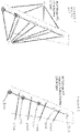
Figure 1 shows an aircraft wing containing a known leading edge high lift system. -
Figure 2 shows a first example of a new type of leading edge high lift system present in an aircraft wing. -
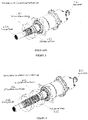
Figure 3 depicts a conventional RGA such as that which may be used in conjunction with the example offigure 1 , by which an output shaft communicates with a pinion or alternative connection to the moving surface. -
Figure 4 depicts a new RGA such as that which may be used in conjunction with the example offigure 2 , by which an output shaft communicates with two separate pinions or alternative connections to two moving surfaces. - A known leading edge high lift system is shown in
figure 1 . As is shown in this figure, the system is configured to move four leading edge surfaces, 10, which in this case are Slats. Themovable surfaces 10 are positioned along the leading edge of the wing and are positioned laterally adjacent to each other along the leading edge so that each extends away from the aircraft fuselage and in the direction of the outermost tip of the wing. - Each individual
movable surface 10 is connected to, and actuated by, two separate and individual rotary gear actuators (RGAs) 11, with afirst RGA 11 being provided at a first, end of themovable surface 10 and asecond RGA 11 being provided at the opposite, second end of themovable surface 10. In use, when the high lift system is activated, eachmovable surface 10 is moved via actuation of the first andsecond RGAs 11 associated with thatsurface 10. Since eachsurface 10 utilises twoRGAs 11, for an aircraft wherein fourmovable surfaces 10 are provided on a wing, sixteen RGAs are needed in total in order to actuate themovable surfaces 10 provided on the wings of the aircraft. -
Figure 3 depicts a conventional RGA such as that which may be used in conjunction with the example offigure 1 , by which an output shaft communicates with a pinion drive or alternative connection to the moving surface. The RGA shown in this figure may be used in a slat actuator arrangement for a conventional high lift architecture. As can be seen in the figure, the RGA comprises aninput shaft 131 and anoutput shaft 132. Around the surface of theoutput shaft 132 there is provided a single surface drive pinion 133 which in use typically interacts with a rack that is connected directly to the surface. - The
through shaft 135 is connected to theRGA input shaft 131 and communicates with transmission shafting that extends to the input shaft of the next RGA. - The new High Lift Systems 200, 300 described herein aim to close the gap between cost and price of known High Lift Systems by providing an actuator that can be used in such a system to thereby simplify and provide a cost effective overall system. The new type of dual-use actuator described herein could also be used in other systems, wherein
- A new type of high lift system 200 is shown in
figure 2 . As can be seen in this figure, the wing may comprise a plurality of, (i.e. at least two)movable surfaces 210A-D. In the example shown infigure 2 , fourmovable surfaces 210A-C are provided on each wing. In other examples a greater or lesser number ofmovable surfaces 210A-D may be provided on each wing and the system of this example 200 is not limited to only four. The plurality ofmovable surfaces 210A-D are provided on the leading edge of the aircraft wing. As is known in the art, the leading edge of the aircraft wing extends outward from the main fuselage of the aircraft and ends at the wing tip. Themovable surfaces 210A-D are therefore provided so as to be positioned along this leading edge so that they are consecutively adjacent to each other along the leading edge in the same way as shown infigure 1 . This system could also be used with other movable surface configurations and is not limited to only this configuration. For example, the system could be used in a position that is not at the leading edge. - In this example, there is a first
movable surface 210A which is positioned adjacent to a secondmovable surface 210B as shown infigure 2 . A first, standard, or non-shared RGA 211a (such as that shown infigure 3 ) may be provided at a first end of the first movable surface 210a and a first new type, or shared RGA 211b (i.e. such as that shown infigure 4 ) is provided at the second, opposite end of the first movable surface 210a. This first shared RGA 211b is called herein a shared RGA because, in contrast to the example shown infigure 3 , the first shared RGA 211b is also connectable/connected to the adjacent, or secondmovable surface 210B and is configured to be shared by both the first and second movable surfaces so that in use it not only actuates movement of the firstmovable surface 210A but also activates movement of the secondmovable surface 210B. - At the opposite, or second end of the second
movable surface 210B, a second shared RGA 211c may also be provided. This second shared RGA 211c is configured not only to actuate and move the secondmovable surface 210B but is also connected to the adjacent thirdmovable surface 210C and is further configured to activate the thirdmovable surface 210C as well as the secondmovable surface 210B. This second shared RGA 211c is therefore shared by the secondmovable surface 210B and the thirdmovable surface 210C. - The third
movable surface 210C is also positioned adjacent to a fourthmovable surface 210D and a third shared RGA 211d is positioned relative to the third 210C and fourthmovable surfaces 210D such that the third shared RGA 211d is connected to both the third 210C and fourth 210D movable surfaces and is configured to actuate both of thesemovable surfaces movable surface 210C and the fourthmovable surface 210D. - Since the fourth
movable surface 210D is the outermost movable surface, a second, conventional, or non-shared RGA 211e (e.g. similar to that shown infigure 3 ) may be provided at the second, most outermost end of the fourthmovable surface 210D, which actuates only that fourthmovable surface 210D as it is the last movable surface in the row. - In this example, since two adjacent movable surfaces are mutually actuated using the same, shared RGA, this high lift system only requires a total of five RGAs in order to actuate four movable surfaces. Therefore, for a single aircraft, which has eight movable surfaces, only ten RGAs are needed. This is greatly reduced in comparison to the known example of
figure 1 wherein sixteen are required for the same number of movable surfaces. -
Figure 4 depicts the features of the shared RGAs as described above with reference tofigure 2 . This is described as being a slat actuator arrangement that may be used in high lift architectures such as that shown infigure 2 . As can be seen in this figure, the RGA 210 comprises aninput shaft 231 and anoutput shaft 232. The input shaft typically receives torque from a transmission shaft. The output shaft is connected to the input shaft via a high ratio gear reduction within the RGA. - The
output shaft 232 of this shared RGA comprises means for connecting not just to one movable surface, but two movable surfaces. This is achieved due to the output shaft comprising a spline or other suitable connection that mutually communicates with a first surface drive pinion 233 (which in use typically interacts with a rack that is connected directly to the first surface) and further comprises a secondsurface drive pinion 234 which in use typically interacts with a rack that is connected directly to the second surface. This can also be achieved in other ways, and the examples described herein are not limited to this. - In use, the though
shaft 235 is connected to theRGA input shaft 231 and communicates with transmission shafting that extends to the input shaft of the next RGA.
Claims (12)
- A rotary geared actuator "RGA" (211b) for actuating movement of a first movable surface (210A) and a second movable surface (210B); the RGA (211b) comprising:an input shaft (231) configured to receive torque in use, andan output shaft (232) comprising means configured to communicate with and move both said first surface (210A) and said second surface (210B) in use.
- The shared RGA of claim 1 wherein said means configured to communicate with and move both of said first movable surface (210A) and said second movable surface (210B) comprises a spline.
- The actuator of claim 2 wherein, in use, said spline is configured to communicate with a first drive pinion of said first movable surface (210A) and further configured to communicate with a second drive pinion of said second surface (210B).
- The RGA of any preceding claim wherein the output shaft (232) is connected to the input shaft (231) via a high ratio gear reduction within the RGA (211b).
- A high lift system (200) for an aircraft wing comprising
said RGA (211b) of any preceding claim, said RGA being a first shared RGA (211b) that is positioned relative to said first and second movable surfaces, such that each of said first and second surfaces shares, and is actuated by, said first shared RGA (211b). - The high lift system of claim 5 further comprising
a plurality of said shared RGAs (211a) positioned relative to a plurality of said movable surfaces, such that each of said plurality of movable surfaces shares, and is actuated by at least one of said shared RGAs (211a). - The high lift system of claim 6 wherein said movable surfaces are positioned in a row and adjacent to each other and said shared RGAs (211a) are positioned between said adjacent movable surfaces.
- The high lift system of claim 7 further comprising a non-shared RGA and wherein a movable surface that is positioned at an end of the row of plurality of adjacent movable surfaces is actuated at its first end by said non-shared RGA and at its second end by one of said shared RGAs.
- A high lift system (200) for an aircraft wing comprising
the RGA of any of claims 1 to 4, wherein said RGA comprises a first shared RGA that is shared by said first movable surface and said second movable surface. - The high lift system of claim 9 further comprising
a first, non-shared RGA (211a) connectable to said first movable surface (210A), the first movable surface being a surface of said aircraft wing, and
said first shared RGA (211b) being connectable to both said first movable surface (210A) and said second movable surface (210B), said second movable surface being a surface of said aircraft wing, and
a second shared RGA (211c) connectable to said second movable surface (210B);
wherein said first non-shared RGA (211a) and said first shared RGA (211b) are configured to actuate said first movable surface (210A);
and wherein said first shared RGA (211b) and said second shared RGA (211c) are configured to actuate said second movable surface (210B). - The system of claim 10
said second shared RGA (211c) being connectable to a third movable surface (210C)
of said aircraft wing and further comprising
a third shared RGA (211d) connectable to said third movable surface (210C) of said aircraft wing and
wherein said second shared RGA (211c) and said third shared RGA (211d) are configured to actuate said third movable surface (210a). - The system of claim 11
said third shared RGA (211d) being connectable to a fourth movable surface (210D) of said aircraft wing and further comprising
a second non-shared RGA (211e) connectable to said fourth movable surface (210D) of said aircraft wing and
wherein said fourth RGA (211d) and said fifth RGA (211e) are configured to actuate said fourth movable surface (210D).
Priority Applications (4)
| Application Number | Priority Date | Filing Date | Title |
|---|---|---|---|
| EP21275045.9A EP4079632B1 (en) | 2021-04-21 | 2021-04-21 | Leading edge high lift architecture |
| CA3151693A CA3151693A1 (en) | 2021-04-21 | 2022-03-08 | Actuator for leading edge high lift architecture |
| BR102022006755-4A BR102022006755A2 (en) | 2021-04-21 | 2022-04-07 | ROTATING GEAR ACTUATOR, E, HIGH ELEVATION SYSTEM |
| US17/720,552 US12534189B2 (en) | 2021-04-21 | 2022-04-14 | Shared actuator for leading edge high lift architecture |
Applications Claiming Priority (1)
| Application Number | Priority Date | Filing Date | Title |
|---|---|---|---|
| EP21275045.9A EP4079632B1 (en) | 2021-04-21 | 2021-04-21 | Leading edge high lift architecture |
Publications (2)
| Publication Number | Publication Date |
|---|---|
| EP4079632A1 true EP4079632A1 (en) | 2022-10-26 |
| EP4079632B1 EP4079632B1 (en) | 2025-08-20 |
Family
ID=75639828
Family Applications (1)
| Application Number | Title | Priority Date | Filing Date |
|---|---|---|---|
| EP21275045.9A Active EP4079632B1 (en) | 2021-04-21 | 2021-04-21 | Leading edge high lift architecture |
Country Status (4)
| Country | Link |
|---|---|
| US (1) | US12534189B2 (en) |
| EP (1) | EP4079632B1 (en) |
| BR (1) | BR102022006755A2 (en) |
| CA (1) | CA3151693A1 (en) |
Citations (3)
| Publication number | Priority date | Publication date | Assignee | Title |
|---|---|---|---|---|
| US4399970A (en) * | 1980-11-13 | 1983-08-23 | The Boeing Company | Wing leading edge slat |
| US4838503A (en) * | 1987-05-13 | 1989-06-13 | British Aerospace Plc | Mechanism for supporting and extending a high lift device for aircraft wings |
| EP2336023A2 (en) * | 2009-12-15 | 2011-06-22 | Hamilton Sundstrand Corporation | Feedback torque limiter |
Family Cites Families (6)
| Publication number | Priority date | Publication date | Assignee | Title |
|---|---|---|---|---|
| US4779822A (en) | 1986-05-23 | 1988-10-25 | Sundstrand Corporation | Actuator system |
| US4979700A (en) * | 1988-10-28 | 1990-12-25 | Curtiss Wright Flight Systems, Inc. | Rotary actuator for leading edge flap of aircraft |
| FR2727477A1 (en) | 1994-11-28 | 1996-05-31 | Aerospatiale | CONICAL ROTARY CYLINDER AND ITS APPLICATION TO THE CONTROL OF AN AIRCRAFT GOVERNOR |
| US10875630B2 (en) | 2016-06-21 | 2020-12-29 | Airbus Canada Limited Partnership | Gust loading management |
| US10538310B2 (en) | 2016-06-29 | 2020-01-21 | Parker-Hannifin Corporation | Near synchronous distributed hydraulic motor driven actuation system |
| US11060566B2 (en) * | 2018-01-19 | 2021-07-13 | The Boeing Company | Apparatus and methods for rigging a torque tube assembly in an aircraft |
-
2021
- 2021-04-21 EP EP21275045.9A patent/EP4079632B1/en active Active
-
2022
- 2022-03-08 CA CA3151693A patent/CA3151693A1/en active Pending
- 2022-04-07 BR BR102022006755-4A patent/BR102022006755A2/en unknown
- 2022-04-14 US US17/720,552 patent/US12534189B2/en active Active
Patent Citations (3)
| Publication number | Priority date | Publication date | Assignee | Title |
|---|---|---|---|---|
| US4399970A (en) * | 1980-11-13 | 1983-08-23 | The Boeing Company | Wing leading edge slat |
| US4838503A (en) * | 1987-05-13 | 1989-06-13 | British Aerospace Plc | Mechanism for supporting and extending a high lift device for aircraft wings |
| EP2336023A2 (en) * | 2009-12-15 | 2011-06-22 | Hamilton Sundstrand Corporation | Feedback torque limiter |
Also Published As
| Publication number | Publication date |
|---|---|
| EP4079632B1 (en) | 2025-08-20 |
| US12534189B2 (en) | 2026-01-27 |
| CA3151693A1 (en) | 2022-10-21 |
| US20220340263A1 (en) | 2022-10-27 |
| BR102022006755A2 (en) | 2022-10-25 |
Similar Documents
| Publication | Publication Date | Title |
|---|---|---|
| US10538310B2 (en) | Near synchronous distributed hydraulic motor driven actuation system | |
| EP1846291B1 (en) | Dual motor dual concentric valve | |
| US4688744A (en) | Jam tolerant rotary actuation system | |
| US8746614B2 (en) | System for actuating at least one positioning flap of an aircraft and a method for monitoring the system | |
| US10215246B2 (en) | Integrated torque limiter/no-back device | |
| US9327824B2 (en) | Adjustment of wings for variable camber for optimum take-off and landing | |
| EP3656663B1 (en) | Aircraft steering system including electromechanical actuator | |
| US20080079381A1 (en) | Motor balanced active user interface assembly | |
| US20120090311A1 (en) | Actuating system for a movable aircraft engine nacelle element, such as a thrust reverser cover | |
| US9809301B2 (en) | Actuator for controlling a flight control surface | |
| CN102094907A (en) | Feedback torque limiter | |
| US12071222B2 (en) | Flight control device and method for increased rigging precision | |
| EP4079632B1 (en) | Leading edge high lift architecture | |
| US10037040B2 (en) | Stability and control augmentation system | |
| US10703463B2 (en) | Easy-to-mount actuator | |
| US9809326B2 (en) | Method for adjusting the play in a high-lift system of an aircraft | |
| US20220228647A1 (en) | Thin wing multi slice rga on leading edge | |
| GB2112967A (en) | Hydraulic valve control and feedback utilizing a harmonic drive differential | |
| US11939042B2 (en) | Control surface actuation synchronization system | |
| US12208881B2 (en) | Rotary actuation for thin wing applications | |
| CN112623193A (en) | Aircraft control surface trimmer control system with control effect follow-up compensation | |
| US11858616B2 (en) | Panel actuation assembly | |
| CN111038693B (en) | Mechanical control system of multi-rotor aircraft | |
| EP0287832A2 (en) | Flight control system for aircraft |
Legal Events
| Date | Code | Title | Description |
|---|---|---|---|
| PUAI | Public reference made under article 153(3) epc to a published international application that has entered the european phase |
Free format text: ORIGINAL CODE: 0009012 |
|
| STAA | Information on the status of an ep patent application or granted ep patent |
Free format text: STATUS: THE APPLICATION HAS BEEN PUBLISHED |
|
| AK | Designated contracting states |
Kind code of ref document: A1 Designated state(s): AL AT BE BG CH CY CZ DE DK EE ES FI FR GB GR HR HU IE IS IT LI LT LU LV MC MK MT NL NO PL PT RO RS SE SI SK SM TR |
|
| STAA | Information on the status of an ep patent application or granted ep patent |
Free format text: STATUS: REQUEST FOR EXAMINATION WAS MADE |
|
| 17P | Request for examination filed |
Effective date: 20230426 |
|
| RBV | Designated contracting states (corrected) |
Designated state(s): AL AT BE BG CH CY CZ DE DK EE ES FI FR GB GR HR HU IE IS IT LI LT LU LV MC MK MT NL NO PL PT RO RS SE SI SK SM TR |
|
| STAA | Information on the status of an ep patent application or granted ep patent |
Free format text: STATUS: EXAMINATION IS IN PROGRESS |
|
| 17Q | First examination report despatched |
Effective date: 20240227 |
|
| GRAP | Despatch of communication of intention to grant a patent |
Free format text: ORIGINAL CODE: EPIDOSNIGR1 |
|
| STAA | Information on the status of an ep patent application or granted ep patent |
Free format text: STATUS: GRANT OF PATENT IS INTENDED |
|
| INTG | Intention to grant announced |
Effective date: 20250321 |
|
| GRAS | Grant fee paid |
Free format text: ORIGINAL CODE: EPIDOSNIGR3 |
|
| GRAA | (expected) grant |
Free format text: ORIGINAL CODE: 0009210 |
|
| STAA | Information on the status of an ep patent application or granted ep patent |
Free format text: STATUS: THE PATENT HAS BEEN GRANTED |
|
| AK | Designated contracting states |
Kind code of ref document: B1 Designated state(s): AL AT BE BG CH CY CZ DE DK EE ES FI FR GB GR HR HU IE IS IT LI LT LU LV MC MK MT NL NO PL PT RO RS SE SI SK SM TR |
|
| REG | Reference to a national code |
Ref country code: GB Ref legal event code: FG4D |
|
| REG | Reference to a national code |
Ref country code: CH Ref legal event code: EP |
|
| REG | Reference to a national code |
Ref country code: IE Ref legal event code: FG4D |
|
| REG | Reference to a national code |
Ref country code: DE Ref legal event code: R096 Ref document number: 602021036565 Country of ref document: DE |
|
| REG | Reference to a national code |
Ref country code: NL Ref legal event code: MP Effective date: 20250820 |
|
| PG25 | Lapsed in a contracting state [announced via postgrant information from national office to epo] |
Ref country code: IS Free format text: LAPSE BECAUSE OF FAILURE TO SUBMIT A TRANSLATION OF THE DESCRIPTION OR TO PAY THE FEE WITHIN THE PRESCRIBED TIME-LIMIT Effective date: 20251220 |
|
| PG25 | Lapsed in a contracting state [announced via postgrant information from national office to epo] |
Ref country code: NO Free format text: LAPSE BECAUSE OF FAILURE TO SUBMIT A TRANSLATION OF THE DESCRIPTION OR TO PAY THE FEE WITHIN THE PRESCRIBED TIME-LIMIT Effective date: 20251120 |
|
| REG | Reference to a national code |
Ref country code: LT Ref legal event code: MG9D |
|
| PG25 | Lapsed in a contracting state [announced via postgrant information from national office to epo] |
Ref country code: PT Free format text: LAPSE BECAUSE OF FAILURE TO SUBMIT A TRANSLATION OF THE DESCRIPTION OR TO PAY THE FEE WITHIN THE PRESCRIBED TIME-LIMIT Effective date: 20251222 |
|
| PG25 | Lapsed in a contracting state [announced via postgrant information from national office to epo] |
Ref country code: FI Free format text: LAPSE BECAUSE OF FAILURE TO SUBMIT A TRANSLATION OF THE DESCRIPTION OR TO PAY THE FEE WITHIN THE PRESCRIBED TIME-LIMIT Effective date: 20250820 |
|
| PG25 | Lapsed in a contracting state [announced via postgrant information from national office to epo] |
Ref country code: HR Free format text: LAPSE BECAUSE OF FAILURE TO SUBMIT A TRANSLATION OF THE DESCRIPTION OR TO PAY THE FEE WITHIN THE PRESCRIBED TIME-LIMIT Effective date: 20250820 Ref country code: NL Free format text: LAPSE BECAUSE OF FAILURE TO SUBMIT A TRANSLATION OF THE DESCRIPTION OR TO PAY THE FEE WITHIN THE PRESCRIBED TIME-LIMIT Effective date: 20250820 |
|
| PG25 | Lapsed in a contracting state [announced via postgrant information from national office to epo] |
Ref country code: GR Free format text: LAPSE BECAUSE OF FAILURE TO SUBMIT A TRANSLATION OF THE DESCRIPTION OR TO PAY THE FEE WITHIN THE PRESCRIBED TIME-LIMIT Effective date: 20251121 |
|
| PG25 | Lapsed in a contracting state [announced via postgrant information from national office to epo] |
Ref country code: SE Free format text: LAPSE BECAUSE OF FAILURE TO SUBMIT A TRANSLATION OF THE DESCRIPTION OR TO PAY THE FEE WITHIN THE PRESCRIBED TIME-LIMIT Effective date: 20250820 |
|
| PG25 | Lapsed in a contracting state [announced via postgrant information from national office to epo] |
Ref country code: LV Free format text: LAPSE BECAUSE OF FAILURE TO SUBMIT A TRANSLATION OF THE DESCRIPTION OR TO PAY THE FEE WITHIN THE PRESCRIBED TIME-LIMIT Effective date: 20250820 |
|
| PG25 | Lapsed in a contracting state [announced via postgrant information from national office to epo] |
Ref country code: PL Free format text: LAPSE BECAUSE OF FAILURE TO SUBMIT A TRANSLATION OF THE DESCRIPTION OR TO PAY THE FEE WITHIN THE PRESCRIBED TIME-LIMIT Effective date: 20250820 Ref country code: BG Free format text: LAPSE BECAUSE OF FAILURE TO SUBMIT A TRANSLATION OF THE DESCRIPTION OR TO PAY THE FEE WITHIN THE PRESCRIBED TIME-LIMIT Effective date: 20250820 |
|
| PG25 | Lapsed in a contracting state [announced via postgrant information from national office to epo] |
Ref country code: RS Free format text: LAPSE BECAUSE OF FAILURE TO SUBMIT A TRANSLATION OF THE DESCRIPTION OR TO PAY THE FEE WITHIN THE PRESCRIBED TIME-LIMIT Effective date: 20251120 |
|
| PG25 | Lapsed in a contracting state [announced via postgrant information from national office to epo] |
Ref country code: ES Free format text: LAPSE BECAUSE OF FAILURE TO SUBMIT A TRANSLATION OF THE DESCRIPTION OR TO PAY THE FEE WITHIN THE PRESCRIBED TIME-LIMIT Effective date: 20250820 |
|
| REG | Reference to a national code |
Ref country code: AT Ref legal event code: MK05 Ref document number: 1827080 Country of ref document: AT Kind code of ref document: T Effective date: 20250820 |
|
| PG25 | Lapsed in a contracting state [announced via postgrant information from national office to epo] |
Ref country code: SM Free format text: LAPSE BECAUSE OF FAILURE TO SUBMIT A TRANSLATION OF THE DESCRIPTION OR TO PAY THE FEE WITHIN THE PRESCRIBED TIME-LIMIT Effective date: 20250820 |
|
| PGFP | Annual fee paid to national office [announced via postgrant information from national office to epo] |
Ref country code: GB Payment date: 20260327 Year of fee payment: 6 |
|
| PG25 | Lapsed in a contracting state [announced via postgrant information from national office to epo] |
Ref country code: DK Free format text: LAPSE BECAUSE OF FAILURE TO SUBMIT A TRANSLATION OF THE DESCRIPTION OR TO PAY THE FEE WITHIN THE PRESCRIBED TIME-LIMIT Effective date: 20250820 |
|
| PG25 | Lapsed in a contracting state [announced via postgrant information from national office to epo] |
Ref country code: AT Free format text: LAPSE BECAUSE OF FAILURE TO SUBMIT A TRANSLATION OF THE DESCRIPTION OR TO PAY THE FEE WITHIN THE PRESCRIBED TIME-LIMIT Effective date: 20250820 |
|
| PG25 | Lapsed in a contracting state [announced via postgrant information from national office to epo] |
Ref country code: IT Free format text: LAPSE BECAUSE OF FAILURE TO SUBMIT A TRANSLATION OF THE DESCRIPTION OR TO PAY THE FEE WITHIN THE PRESCRIBED TIME-LIMIT Effective date: 20250820 |
|
| PG25 | Lapsed in a contracting state [announced via postgrant information from national office to epo] |
Ref country code: CZ Free format text: LAPSE BECAUSE OF FAILURE TO SUBMIT A TRANSLATION OF THE DESCRIPTION OR TO PAY THE FEE WITHIN THE PRESCRIBED TIME-LIMIT Effective date: 20250820 |
|
| PG25 | Lapsed in a contracting state [announced via postgrant information from national office to epo] |
Ref country code: SK Free format text: LAPSE BECAUSE OF FAILURE TO SUBMIT A TRANSLATION OF THE DESCRIPTION OR TO PAY THE FEE WITHIN THE PRESCRIBED TIME-LIMIT Effective date: 20250820 Ref country code: EE Free format text: LAPSE BECAUSE OF FAILURE TO SUBMIT A TRANSLATION OF THE DESCRIPTION OR TO PAY THE FEE WITHIN THE PRESCRIBED TIME-LIMIT Effective date: 20250820 |