EP4079628A1 - Acoustic redirection systems and methods for urban air mobility vehicles - Google Patents
Acoustic redirection systems and methods for urban air mobility vehicles Download PDFInfo
- Publication number
- EP4079628A1 EP4079628A1 EP22169738.6A EP22169738A EP4079628A1 EP 4079628 A1 EP4079628 A1 EP 4079628A1 EP 22169738 A EP22169738 A EP 22169738A EP 4079628 A1 EP4079628 A1 EP 4079628A1
- Authority
- EP
- European Patent Office
- Prior art keywords
- shield
- rotor
- uam
- vehicle
- acoustic
- Prior art date
- Legal status (The legal status is an assumption and is not a legal conclusion. Google has not performed a legal analysis and makes no representation as to the accuracy of the status listed.)
- Granted
Links
Images



Classifications
-
- B—PERFORMING OPERATIONS; TRANSPORTING
- B64—AIRCRAFT; AVIATION; COSMONAUTICS
- B64C—AEROPLANES; HELICOPTERS
- B64C11/00—Propellers, e.g. of ducted type; Features common to propellers and rotors for rotorcraft
- B64C11/001—Shrouded propellers
-
- B—PERFORMING OPERATIONS; TRANSPORTING
- B64—AIRCRAFT; AVIATION; COSMONAUTICS
- B64C—AEROPLANES; HELICOPTERS
- B64C27/00—Rotorcraft; Rotors peculiar thereto
- B64C27/20—Rotorcraft characterised by having shrouded rotors, e.g. flying platforms
-
- B—PERFORMING OPERATIONS; TRANSPORTING
- B64—AIRCRAFT; AVIATION; COSMONAUTICS
- B64U—UNMANNED AERIAL VEHICLES [UAV]; EQUIPMENT THEREFOR
- B64U30/00—Means for producing lift; Empennages; Arrangements thereof
- B64U30/20—Rotors; Rotor supports
- B64U30/26—Ducted or shrouded rotors
-
- B—PERFORMING OPERATIONS; TRANSPORTING
- B64—AIRCRAFT; AVIATION; COSMONAUTICS
- B64U—UNMANNED AERIAL VEHICLES [UAV]; EQUIPMENT THEREFOR
- B64U10/00—Type of UAV
- B64U10/10—Rotorcrafts
- B64U10/13—Flying platforms
- B64U10/14—Flying platforms with four distinct rotor axes, e.g. quadcopters
Definitions
- the present disclosure (invention) relates to acoustic redirection systems and methods, and more specifically, to acoustic redirection systems and methods for Urban Air Mobility (UAM) vehicles.
- UAM Urban Air Mobility
- UAM Urban Air Mobility
- Air Taxis Air Taxis
- an acoustic system for an Urban Air Mobility (UAM) vehicle comprising: a first shield configured to be disposed around a rotor of the UAM vehicle, the first shield having an annular shape, the first shield configured to be disposed radially outward from a blade tip of a rotary blade, the first shield configured to redirect sound waves from a substantially radial direction to a second direction, the second direction being orthogonal to the radial direction.
- UAM Urban Air Mobility
- the first shield comprises a radially inner surface having a concave shape.
- the first shield may comprise an upper angled wall and a lower angled wall, a first inner surface of the upper angled wall configured to form a first acute angle with a strut, a second inner surface of the lower angled wall configured to form a second acute angle with the strut.
- the acoustic system may further comprise the rotor.
- the acoustic system may further comprise a central hub, the rotor configured to rotate around the central hub, the first shield spaced apart radially from the central hub.
- the acoustic system may further comprise a second shield configured to be disposed around a second rotor and a third shield configured to be disposed around a third rotor, the second shield and the third shield in accordance with the first shield.
- the acoustic system may further comprise a fourth shield configured to be disposed around a fourth rotor, the fourth shield in accordance with the first shield.
- a rotor system for an Urban Air Mobility (UAM) vehicle comprising: a central hub; a drive shaft operably coupled to the central hub; at least two rotary blades extending radially outward from the drive shaft; and a shield spaced apart radially outward from the at least two rotary blades, the shield being annular in shape, the shield configured to redirect sound waves from a substantially radial direction to a second direction, the second direction being orthogonal to the substantially radial direction.
- UAM Urban Air Mobility
- the shield comprises a radially inner surface having a concave shape.
- the rotor system may further comprise at least two struts extending from the central hub radially outward to the shield.
- the shield may comprise an upper angled surface and a lower angled surface, the upper angled surface forming a first acute angle with the at least two struts, the lower angled surface forming a second acute angle with the at least two struts.
- the rotor system may form a portion of a propulsion system for the UAM vehicle.
- the shield may comprise a thermoplastic material.
- the UAM vehicle comprises: an airframe defining a cabin; and a propulsion system comprising a plurality of rotor systems, each rotor system including: a central hub; a drive shaft operably coupled to the central hub; at least two rotary blades configured to rotate about the central hub; and a shield having an acoustic redirection system, the shield having an annular shape.
- the shield of each rotor system is spaced apart radially from a blade tip of a rotary blade in the at least two rotary blades.
- the acoustic redirection system of each rotor system is configured to redirect sound waves from a substantially radial direction to a second direction, the second direction being substantially orthogonal to the substantially radial direction.
- the shield of each rotor system may comprise a radially inner surface having a concave shape.
- the rotor system may further comprise at least two struts extending from the central hub radially outward to the shield.
- the shield of each rotor system may comprise an upper angled wall and a lower angled wall, a first internal surface of the upper angled wall forming a first acute angle with the at least two struts, a second internal surface of the lower angled wall forming a second acute angle with the at least two struts.
- the UAM vehicle may further comprise a plurality of support arms, each support arm configured to structurally support a corresponding rotor system in the plurality of rotor systems.
- any of the method or process descriptions may be executed in any order and are not necessarily limited to the order presented.
- any reference to singular includes plural embodiments, and any reference to more than one component or step may include a singular embodiment or step.
- any reference to tacked, attached, fixed, coupled, connected or the like may include permanent, removable, temporary, partial, full and/or any other possible attachment option.
- any reference to without contact (or similar phrases) may also include reduced contact or minimal contact.
- Surface shading lines may be used throughout the figures to denote different parts but not necessarily to denote the same or different materials.
- a perspective view of an Urban Air Mobility (UAM) vehicle 10 may include an airframe 12 defining a cabin 14, landing skids 16, and a propulsion system 18. Although illustrated as including landing skids 16, any type of landing gear is within the scope of this disclosure.
- the propulsion system 18 includes a plurality of rotor systems 20. Although illustrated as including four rotor systems 20, any number of rotor systems is within the scope of this disclosure.
- each rotor system in the plurality of rotor systems 20 may be configured for a fixed angle of attack (i.e., including a rotor configured to maintain a same plane relative to the airframe 12) or configured for a variable angle of attack (i.e., including a rotor configured to operate in variable planes relative to the airframe 12).
- each rotor system in the plurality of rotor systems 20 may be moveable over any number of degrees of freedom.
- each rotor system in the plurality of rotor systems 20 may be configured to vary pitch, roll, and/or yaw of a respective rotor in the plurality of rotor system 20.
- the UAM vehicle 10 may further comprise a support arm 22 for each rotor system in the plurality of rotor system 20.
- a first rotor system 21 in the plurality of rotor systems 20 includes a support arm 22 extending outward from the airframe 12 to a shield 110 of an acoustic redirection system 100.
- the support arm 22 extends outward in a horizontal direction (e.g., parallel to a ground surface when UAM vehicle 10 is on the ground surface +/- 30 degrees). Although described herein as being +/- 30 degrees from a ground surface, the present disclosure is not limited in this regard. For example, one skilled in the art may recognize various angles for a support arm 22 and still be within the scope of this disclosure.
- the support arm 22 may couple a rotor system (e.g., first rotor system 21) to the airframe 12, in accordance with various embodiments.
- the UAM vehicle 10 further comprises an acoustic redirection system for each rotor system in the plurality of rotor system 20.
- UAM vehicle 10 includes the acoustic redirection system 100 for the first rotor system 21.
- the acoustic redirection system 100 includes a shield 110 disposed radially outward from a rotor 120 of first rotor system 21.
- the shield 110 is annular in shape and configured to surround the rotor in the radially outward direction.
- the acoustic redirection system 100 is configured to re-direct sound radiation (i.e., in a direction orthogonal to the radial direction) below and above the UAM vehicle 10.
- Below refers to a direction towards a ground surface when the UAM vehicle 10 is on a ground surface (e.g., when skids 16 are in contact with the ground surface).
- “Above” as defined herein refers to a direction away from a ground surface when the UAM vehicle 10 is on the ground surface.
- the acoustic redirection system 100 is configured to re-direct sound waves, in accordance with various embodiments. In various embodiments, by utilizing acoustic redirection system 100 as described herein, the UAM vehicle 10 may limit noise to a vertical direction.
- the UAM vehicle 10 may be configured to take off and land vertically over a community airport or the like, and the acoustic redirection system 100 is configured to ensure the noise of the rotor 120 is limited to the airport, in accordance with various embodiments.
- the acoustic redirection system 100 includes the shield 110 disposed radially outward of the rotor 120.
- the rotor 120 includes a drive shaft 122 and rotary blades 124 and a hub 126. Any number of rotary blades 124 is within the scope of this disclosure.
- the drive shaft 122 and the rotary blades 124 are configured to rotate about the hub 126 to generate lift and/or thrust to propel UAM vehicle 10 from FIG. 1 , in accordance with various embodiments.
- the acoustic redirection system 100 further comprises at least two struts 130 coupling the hub 126 to the shield 110.
- the at least two struts 130 provide structural support for the rotor 120, in accordance with various embodiments.
- the shield 110 is annular in shape and extends axially from a first end 113 to a second end 115.
- the shield 110 is spaced apart from rotary blades in a radial direction by a distance D1.
- the distance D1 is sized and configured to limit any impact on lift generated by the rotor 120.
- shield 110 is sized and configured for acoustic redirection while limiting an impact to aerodynamics of the first rotor system 21, in accordance with various embodiments.
- the shield 110 includes a radially inner surface 112 and a radially outer surface 114.
- the radially inner surface 112 defines a concave surface 116
- the radially outer surface 114 defines a convex surface 118.
- the shield 110 is configured to redirect sound waves from a substantially radial direction to a substantially vertical direction. "Substantially,” as referred to herein is +/- 30° relative to the direction specified, in accordance with various embodiments. By redirecting sound waves from a radial direction to a substantially vertical direction an area effected by noise from the UAM vehicle 10 from FIG. 1 may be significantly reduced, in accordance with various embodiments.
- the UAM vehicle 10 may have community airports (i.e., pickup and drop off locations for the UAM vehicle 10 from FIG. 1 ).
- the UAM vehicle 10 may take off vertically to a predetermined height above the airport prior to traveling to a destination. During the time from take off until the predetermined height, sound may be directed in an upward direction via the shield 110 and a downward direction via the shield 110. Since the community airport may be below the UAM vehicle 10 from FIG. 1 during the take off event, only the community airport may here the noise. Thus, a surrounding community may experience little to no sound from the propulsion system 18 of the UAM vehicle 10 due to the shield 110 of the acoustic redirection system 100, in accordance with various embodiments.
- the acoustic redirection system 200 may comprise a shield 210 comprising angled walls (i.e., upper wall 212 and lower wall 214).
- An internal surface of the angled walls 212, 214 may form an acute angle with the at least two struts 130, in accordance with various embodiments.
- the angled walls 212, 214 of the shield 210 may be configured to redirect sound waves from the rotor 120, during operation of the UAM vehicle 10 from FIG.
- the at least two struts 130 may be coupled to a vertex 213 of angled walls 212, 214.
- the at least two struts 130 may be coupled to a lower wall 314 directly with the upper wall 312 being disposed above (i.e., in a positive z-direction defined by axis of rotation for rotor 120) from an intersection 313 between lower wall 312 and the at least two struts 130.
- angled walls of an acoustic redirection system 300, 400 may form a perpendicular angle (e.g., angled walls 312, 314 of acoustic redirection system 300 of FIG. 4 ) or an obtuse angle (e.g., angled walls 412, 414 of acoustic redirection system 400 of FIG.
- the acoustic redirection systems 300, 400 are configured to redirect a majority of the sound waves in a positive Z-direction (i.e., in a forward direction as defined by the rotor 120).
- a decibel level below and outward from the UAM vehicle 10 from FIG. 1 may be significantly reduced relative to a UAM vehicle without acoustic redirection systems 300, 400.
- a cross-sectional view of an acoustic system 500 is illustrated, in accordance with various embodiments.
- the acoustic system 500 is in accordance with acoustic redirection system 200 and further comprising an acoustic absorption system 501.
- the acoustic absorption system 501 is configured to at least partially absorb sound waves from the rotor 120, in accordance with various embodiments.
- the acoustic absorption system 501 comprises a shield 510 including acoustic liners 512, 514 coupled to the angled walls 212, 214 respectively.
- the acoustic liners 512, 514 may each comprise a perforated screen, a backskin and a honeycomb core disposed between the backskin and the perforated screen, in accordance with various embodiments.
- the backskin may be adjacent to the angled walls 212, 214 and the perforated screen may be disposed radially inward toward the hub of rotor 120.
- the shields 110, 210, 310, 410, 510 from FIGs. 2 and 3 are light weight components configured to reduce noise propagation from the propulsion system 18 from FIG. 1 in a radial direction.
- shields 110, 210, 310, 410, 510 may be non-structural components (i.e., shields 110, 210 may not support rotor 120 in a structural manner).
- the shields 110, 210, 310, 410, 510 may be made of a thermoplastic material such as polycarbonate, acrylic, polystyrene, high-density polyethylene, or the like.
- 1-6 may provide cost and weight benefits, in addition to noise reduction benefits for UAM vehicle 10 from FIG. 1 .
- typical UAM vehicles have open ended rotors, which propagate sound radially. When a typical UAM vehicle is flying at a low altitude, the sound propagating radially may impact a community.
- the sound waves may be redirected, at least partially in a vertical direction (i.e., in a direction of travel defined by rotor 120) and/or managed to reduce noise within a particular radius of a UAM vehicle 10 from FIG. 1 .
- references to "various embodiments”, “one embodiment”, “an embodiment”, “an example embodiment”, etc. indicate that the embodiment described may include a particular feature, structure, or characteristic, but every embodiment may not necessarily include the particular feature, structure, or characteristic. Moreover, such phrases are not necessarily referring to the same embodiment. Further, when a particular feature, structure, or characteristic is described in connection with an embodiment, it is submitted that it is within the knowledge of one skilled in the art to affect such feature, structure, or characteristic in connection with other embodiments whether or not explicitly described. After reading the description, it will be apparent to one skilled in the relevant art(s) how to implement the disclosure in alternative embodiments.
Landscapes
- Engineering & Computer Science (AREA)
- Aviation & Aerospace Engineering (AREA)
- Mechanical Engineering (AREA)
- Soundproofing, Sound Blocking, And Sound Damping (AREA)
- Physics & Mathematics (AREA)
- Acoustics & Sound (AREA)
- Multimedia (AREA)
- Body Structure For Vehicles (AREA)
Abstract
Description
- The present disclosure (invention) relates to acoustic redirection systems and methods, and more specifically, to acoustic redirection systems and methods for Urban Air Mobility (UAM) vehicles.
- Urban Air Mobility (UAM) vehicles, or Air Taxis, is a fast developing technology forecasted to operate in major U.S. cities in 2030. UAM vehicles may be much quieter relative to helicopters. Due to still being in preliminary development, various obstacles to wide adoption of UAM vehicles still remain.
- According to an aspect of the present invention, there is provided an acoustic system for an Urban Air Mobility (UAM) vehicle. The acoustic system comprises: a first shield configured to be disposed around a rotor of the UAM vehicle, the first shield having an annular shape, the first shield configured to be disposed radially outward from a blade tip of a rotary blade, the first shield configured to redirect sound waves from a substantially radial direction to a second direction, the second direction being orthogonal to the radial direction.
- In various embodiments, the first shield comprises a radially inner surface having a concave shape. The first shield may comprise an upper angled wall and a lower angled wall, a first inner surface of the upper angled wall configured to form a first acute angle with a strut, a second inner surface of the lower angled wall configured to form a second acute angle with the strut. The acoustic system may further comprise the rotor. The acoustic system may further comprise a central hub, the rotor configured to rotate around the central hub, the first shield spaced apart radially from the central hub. The acoustic system may further comprise a second shield configured to be disposed around a second rotor and a third shield configured to be disposed around a third rotor, the second shield and the third shield in accordance with the first shield. The acoustic system may further comprise a fourth shield configured to be disposed around a fourth rotor, the fourth shield in accordance with the first shield.
- According to another aspect of the present invention, there is provided a rotor system for an Urban Air Mobility (UAM) vehicle. The rotor system comprises: a central hub; a drive shaft operably coupled to the central hub; at least two rotary blades extending radially outward from the drive shaft; and a shield spaced apart radially outward from the at least two rotary blades, the shield being annular in shape, the shield configured to redirect sound waves from a substantially radial direction to a second direction, the second direction being orthogonal to the substantially radial direction.
- In various embodiments, the shield comprises a radially inner surface having a concave shape. The rotor system may further comprise at least two struts extending from the central hub radially outward to the shield. The shield may comprise an upper angled surface and a lower angled surface, the upper angled surface forming a first acute angle with the at least two struts, the lower angled surface forming a second acute angle with the at least two struts. The rotor system may form a portion of a propulsion system for the UAM vehicle. The shield may comprise a thermoplastic material.
- According to another aspect of the present invention, there is an Urban Air Mobility (UAM) vehicle. The UAM vehicle comprises: an airframe defining a cabin; and a propulsion system comprising a plurality of rotor systems, each rotor system including: a central hub; a drive shaft operably coupled to the central hub; at least two rotary blades configured to rotate about the central hub; and a shield having an acoustic redirection system, the shield having an annular shape.
- In various embodiments, the shield of each rotor system is spaced apart radially from a blade tip of a rotary blade in the at least two rotary blades. The acoustic redirection system of each rotor system is configured to redirect sound waves from a substantially radial direction to a second direction, the second direction being substantially orthogonal to the substantially radial direction. The shield of each rotor system may comprise a radially inner surface having a concave shape. The rotor system may further comprise at least two struts extending from the central hub radially outward to the shield. The shield of each rotor system may comprise an upper angled wall and a lower angled wall, a first internal surface of the upper angled wall forming a first acute angle with the at least two struts, a second internal surface of the lower angled wall forming a second acute angle with the at least two struts. The UAM vehicle may further comprise a plurality of support arms, each support arm configured to structurally support a corresponding rotor system in the plurality of rotor systems.
- The foregoing features and elements may be combined in various combinations without exclusivity, unless expressly indicated otherwise. These features and elements as well as the operation thereof will become more apparent in light of the following description and the accompanying drawings. It should be understood, however, the following description and drawings are intended to be exemplary in nature and non-limiting.
- The subject matter of the present invention is particularly pointed out and distinctly claimed in the concluding portion of the specification. A more complete understanding of the present invention, however, may best be obtained by referring to the detailed description and claims when considered in connection with the following illustrative figures. In the following figures, like reference numbers refer to similar elements and steps throughout the figures.
-
FIG. 1 illustrates a perspective view of an Urban Air Mobility vehicle, in accordance with various embodiments; -
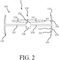
FIG. 2 illustrates a cross sectional view of an acoustic system for a UAM vehicle, in accordance with various embodiments; -
FIG. 3 illustrates a cross sectional view of an acoustic system for a UAM vehicle, in accordance with various embodiments -
FIG. 4 illustrates a cross sectional view of an acoustic system for a UAM vehicle, in accordance with various embodiments -
FIG. 5 illustrates a cross sectional view of an acoustic system for a UAM vehicle, in accordance with various embodiments -
FIG. 6 illustrates a cross sectional view of an acoustic system for a UAM vehicle, in accordance with various embodiments. - The detailed description of exemplary embodiments herein makes reference to the accompanying drawings, which show exemplary embodiments by way of illustration. While these exemplary embodiments are described in sufficient detail to enable those skilled in the art to practice the disclosures, it should be understood that other embodiments may be realized and that logical changes and adaptations in design and construction may be made in accordance with this disclosure and the teachings herein. Thus, the detailed description herein is presented for purposes of illustration only and not of limitation.
- The scope of the disclosure is defined by the appended claims and their legal equivalents rather than by merely the examples described. For example, the steps recited in any of the method or process descriptions may be executed in any order and are not necessarily limited to the order presented. Furthermore, any reference to singular includes plural embodiments, and any reference to more than one component or step may include a singular embodiment or step. Also, any reference to tacked, attached, fixed, coupled, connected or the like may include permanent, removable, temporary, partial, full and/or any other possible attachment option. Additionally, any reference to without contact (or similar phrases) may also include reduced contact or minimal contact. Surface shading lines may be used throughout the figures to denote different parts but not necessarily to denote the same or different materials.
- Referring now to
FIG. 1 , a perspective view of an Urban Air Mobility (UAM)vehicle 10 may include anairframe 12 defining acabin 14,landing skids 16, and apropulsion system 18. Although illustrated as includinglanding skids 16, any type of landing gear is within the scope of this disclosure. In various embodiments, thepropulsion system 18 includes a plurality ofrotor systems 20. Although illustrated as including fourrotor systems 20, any number of rotor systems is within the scope of this disclosure. - In various embodiments, each rotor system in the plurality of
rotor systems 20 may be configured for a fixed angle of attack (i.e., including a rotor configured to maintain a same plane relative to the airframe 12) or configured for a variable angle of attack (i.e., including a rotor configured to operate in variable planes relative to the airframe 12). In this regard, each rotor system in the plurality ofrotor systems 20 may be moveable over any number of degrees of freedom. For example, each rotor system in the plurality ofrotor systems 20 may be configured to vary pitch, roll, and/or yaw of a respective rotor in the plurality ofrotor system 20. - In various embodiments, the
UAM vehicle 10 may further comprise asupport arm 22 for each rotor system in the plurality ofrotor system 20. For example, afirst rotor system 21 in the plurality ofrotor systems 20 includes asupport arm 22 extending outward from theairframe 12 to ashield 110 of anacoustic redirection system 100. In various embodiments, thesupport arm 22 extends outward in a horizontal direction (e.g., parallel to a ground surface when UAMvehicle 10 is on the ground surface +/- 30 degrees). Although described herein as being +/- 30 degrees from a ground surface, the present disclosure is not limited in this regard. For example, one skilled in the art may recognize various angles for asupport arm 22 and still be within the scope of this disclosure. Thesupport arm 22 may couple a rotor system (e.g., first rotor system 21) to theairframe 12, in accordance with various embodiments. - In various embodiments, the
UAM vehicle 10 further comprises an acoustic redirection system for each rotor system in the plurality ofrotor system 20. For example,UAM vehicle 10 includes theacoustic redirection system 100 for thefirst rotor system 21. Theacoustic redirection system 100 includes ashield 110 disposed radially outward from arotor 120 offirst rotor system 21. Theshield 110 is annular in shape and configured to surround the rotor in the radially outward direction. In various embodiments, theacoustic redirection system 100 is configured to re-direct sound radiation (i.e., in a direction orthogonal to the radial direction) below and above theUAM vehicle 10. "Below" as defined herein refers to a direction towards a ground surface when theUAM vehicle 10 is on a ground surface (e.g., when skids 16 are in contact with the ground surface). "Above" as defined herein refers to a direction away from a ground surface when theUAM vehicle 10 is on the ground surface. In this regard, theacoustic redirection system 100 is configured to re-direct sound waves, in accordance with various embodiments. In various embodiments, by utilizingacoustic redirection system 100 as described herein, theUAM vehicle 10 may limit noise to a vertical direction. In this regard, theUAM vehicle 10 may be configured to take off and land vertically over a community airport or the like, and theacoustic redirection system 100 is configured to ensure the noise of therotor 120 is limited to the airport, in accordance with various embodiments. - Referring now to
FIG. 2 , a cross-section view of anacoustic redirection system 100 for theUAM vehicle 10 fromFIG. 1 is illustrated, in accordance with various embodiments. In various embodiments, theacoustic redirection system 100 includes theshield 110 disposed radially outward of therotor 120. Therotor 120 includes adrive shaft 122 androtary blades 124 and ahub 126. Any number ofrotary blades 124 is within the scope of this disclosure. Thedrive shaft 122 and therotary blades 124 are configured to rotate about thehub 126 to generate lift and/or thrust to propelUAM vehicle 10 fromFIG. 1 , in accordance with various embodiments. In various embodiments, theacoustic redirection system 100 further comprises at least twostruts 130 coupling thehub 126 to theshield 110. The at least twostruts 130 provide structural support for therotor 120, in accordance with various embodiments. - In various embodiments, the
shield 110 is annular in shape and extends axially from afirst end 113 to asecond end 115. Theshield 110 is spaced apart from rotary blades in a radial direction by a distance D1. In various embodiments, the distance D1 is sized and configured to limit any impact on lift generated by therotor 120. In this regard,shield 110 is sized and configured for acoustic redirection while limiting an impact to aerodynamics of thefirst rotor system 21, in accordance with various embodiments. - In various embodiments, the
shield 110 includes a radiallyinner surface 112 and a radiallyouter surface 114. In various embodiments, the radiallyinner surface 112 defines aconcave surface 116, and the radiallyouter surface 114 defines aconvex surface 118. In various embodiments, theshield 110 is configured to redirect sound waves from a substantially radial direction to a substantially vertical direction. "Substantially," as referred to herein is +/- 30° relative to the direction specified, in accordance with various embodiments. By redirecting sound waves from a radial direction to a substantially vertical direction an area effected by noise from theUAM vehicle 10 fromFIG. 1 may be significantly reduced, in accordance with various embodiments. For example, theUAM vehicle 10 may have community airports (i.e., pickup and drop off locations for theUAM vehicle 10 fromFIG. 1 ). In this regard, theUAM vehicle 10 may take off vertically to a predetermined height above the airport prior to traveling to a destination. During the time from take off until the predetermined height, sound may be directed in an upward direction via theshield 110 and a downward direction via theshield 110. Since the community airport may be below theUAM vehicle 10 fromFIG. 1 during the take off event, only the community airport may here the noise. Thus, a surrounding community may experience little to no sound from thepropulsion system 18 of theUAM vehicle 10 due to theshield 110 of theacoustic redirection system 100, in accordance with various embodiments. - Referring now to
FIG. 3 , a cross-section view of anacoustic redirection system 200 for theUAM vehicle 10 fromFIG. 1 is illustrated, in accordance with various embodiments. In various embodiments, theacoustic redirection system 200 may comprise ashield 210 comprising angled walls (i.e.,upper wall 212 and lower wall 214). An internal surface of theangled walls struts 130, in accordance with various embodiments. In this regard, theangled walls shield 210 may be configured to redirect sound waves from therotor 120, during operation of theUAM vehicle 10 fromFIG. 1 , from a substantially radial direction to a substantially vertical direction similar to theconcave surface 116 ofshield 110 fromFIG. 2 , in accordance with various embodiments. In various embodiments, the at least twostruts 130 may be coupled to avertex 213 of angledwalls - In various embodiments, with brief reference to
FIG. 4 , the at least twostruts 130 may be coupled to alower wall 314 directly with theupper wall 312 being disposed above (i.e., in a positive z-direction defined by axis of rotation for rotor 120) from anintersection 313 betweenlower wall 312 and the at least two struts 130. In various embodiments, angled walls of anacoustic redirection system walls acoustic redirection system 300 ofFIG. 4 ) or an obtuse angle (e.g., angledwalls acoustic redirection system 400 ofFIG. 5 ). In various embodiments, theacoustic redirection systems UAM vehicle 10 fromFIG. 1 may be significantly reduced relative to a UAM vehicle withoutacoustic redirection systems - Referring now to
FIG. 6 , a cross-sectional view of anacoustic system 500 is illustrated, in accordance with various embodiments. In various embodiments, theacoustic system 500 is in accordance withacoustic redirection system 200 and further comprising anacoustic absorption system 501. Theacoustic absorption system 501 is configured to at least partially absorb sound waves from therotor 120, in accordance with various embodiments. - In various embodiments, the
acoustic absorption system 501 comprises ashield 510 includingacoustic liners angled walls acoustic liners angled walls rotor 120. - In various embodiments, the
shields FIGs. 2 and3 are light weight components configured to reduce noise propagation from thepropulsion system 18 fromFIG. 1 in a radial direction. For example, shields 110, 210, 310, 410, 510 may be non-structural components (i.e., shields 110, 210 may not supportrotor 120 in a structural manner). Theshields acoustic redirection system acoustic system 500 fromFIG. 1-6 may provide cost and weight benefits, in addition to noise reduction benefits forUAM vehicle 10 fromFIG. 1 . For example, typical UAM vehicles have open ended rotors, which propagate sound radially. When a typical UAM vehicle is flying at a low altitude, the sound propagating radially may impact a community. Thus, by surrounding therotor 120 withshield UAM vehicle 10 fromFIG. 1 . - Benefits, other advantages, and solutions to problems have been described herein with regard(s) to specific embodiments. Furthermore, the connecting lines shown in the various figures contained herein are intended to represent exemplary functional relationships and/or physical couplings between the various elements. It should be noted that many alternative or additional functional relationships or physical connections may be present in a practical system. However, the benefits, advantages, solutions to problems, and any elements that may cause any benefit, advantage, or solution to occur or become more pronounced are not to be construed as critical, required, or essential features or elements of the disclosures. The scope of the disclosures is accordingly to be limited by nothing other than the appended claims and their legal equivalents, in which reference to an element in the singular is not intended to mean "one and only one" unless explicitly so stated, but rather "one or more." Moreover, where a phrase similar to "at least one of A, B, or C" is used in the claims, it is intended that the phrase be interpreted to mean that A alone may be present in an embodiment, B alone may be present in an embodiment, C alone may be present in an embodiment, or that any combination of the elements A, B and C may be present in a single embodiment; for example, A and B, A and C, B and C, or A and B and C.
- Systems, methods and apparatus are provided herein. In the detailed description herein, references to "various embodiments", "one embodiment", "an embodiment", "an example embodiment", etc., indicate that the embodiment described may include a particular feature, structure, or characteristic, but every embodiment may not necessarily include the particular feature, structure, or characteristic. Moreover, such phrases are not necessarily referring to the same embodiment. Further, when a particular feature, structure, or characteristic is described in connection with an embodiment, it is submitted that it is within the knowledge of one skilled in the art to affect such feature, structure, or characteristic in connection with other embodiments whether or not explicitly described. After reading the description, it will be apparent to one skilled in the relevant art(s) how to implement the disclosure in alternative embodiments.
- Furthermore, no element, component, or method step in the present disclosure is intended to be dedicated to the public regardless of whether the element, component, or method step is explicitly recited in the claims. As used herein, the terms "comprises", "comprising", or any other variation thereof, are intended to cover a non-exclusive inclusion, such that a process, method, article, or apparatus that comprises a list of elements does not include only those elements but may include other elements not expressly listed or inherent to such process, method, article, or apparatus.
Claims (15)
- An acoustic system (100; 200; 300; 400; 500) for an Urban Air Mobility (UAM) vehicle (10), the acoustic system (100; 200; 300; 400; 500) comprising:
a first shield (110; 210; 310; 410; 510) configured to be disposed around a rotor (120) of the UAM vehicle (10), the first shield (110; 210; 310; 410; 510) having an annular shape, the first shield (110; 210; 310; 410; 510) configured to be disposed radially outward from a blade tip of a rotary blade (124), the first shield (110; 210; 310; 410; 510) configured to redirect sound waves from a substantially radial direction to a second direction, the second direction being orthogonal to the radial direction. - The acoustic system (100) of claim 1, wherein the first shield (110) comprises a radially inner surface (116) having a concave shape.
- The acoustic system (200; 500) of claim 1, wherein the first shield (210; 510) comprises an upper angled wall (212) and a lower angled wall (214), a first inner surface of the upper angled wall (212) configured to form a first acute angle with a strut (130), a second inner surface of the lower angled wall (214) configured to form a second acute angle with the strut (130).
- The acoustic system (100; 200; 300; 400; 500) of any preceding claim, further comprising:the rotor (120); and, optionally,a central hub (126), the rotor (120) configured to rotate around the central hub (126), the first shield (110; 210; 310; 410; 510) spaced apart radially from the central hub (126).
- The acoustic system (100; 200; 300; 400; 500) of any preceding claim, further comprising:a second shield configured to be disposed around a second rotor and a third shield configured to be disposed around a third rotor, the second shield and the third shield in accordance with the first shield (110; 210; 310; 410; 510); and, optionally,a fourth shield configured to be disposed around a fourth rotor, the fourth shield in accordance with the first shield (110; 210; 310; 410; 510).
- A rotor system (21) for an Urban Air Mobility (UAM) vehicle (10), the rotor system (20) comprising:a central hub (126);a drive shaft (122) operably coupled to the central hub (126);at least two rotary blades (124) extending radially outward from the drive shaft (122); anda shield (110; 210; 310; 410; 510) spaced apart radially outward from the at least two rotary blades (124), the shield (110; 210; 310; 410; 510) being annular in shape, the shield (110; 210; 310; 410; 510) configured to redirect sound waves from a substantially radial direction to a second direction, the second direction being orthogonal to the substantially radial direction.
- The rotor system (21) of claim 6, wherein:the rotor system (21) forms a portion of a propulsion system (18) for the UAM vehicle (10); and/orthe shield (110; 210; 310; 410; 510) comprises a thermoplastic material.
- The rotor system (21) of claim 6 or 7, wherein the shield (110) comprises a radially inner surface (116) having a concave shape.
- An Urban Air Mobility (UAM) vehicle (10), comprising:an airframe (12) defining a cabin (14); anda propulsion system (18) comprising a plurality of rotor systems (20), each rotor system (21) including:a central hub (126);a drive shaft (122) operably coupled to the central hub (126);at least two rotary blades (124) configured to rotate about the central hub (126); anda shield (110; 210; 310; 410; 510) having an acoustic redirection system (100; 200; 300; 400; 500), the shield (110; 210; 310; 410; 510) having an annular shape.
- The UAM vehicle (10) of claim 9, wherein the shield (110; 210; 310; 410; 510) of each rotor system (21) is spaced apart radially from a blade tip of a rotary blade (124) in the at least two rotary blades (124).
- The UAM vehicle of claim 9 or 10, wherein the acoustic redirection system (100; 200; 300; 400; 500) of each rotor system (21) is configured to redirect sound waves from a substantially radial direction to a second direction, the second direction being substantially orthogonal to the substantially radial direction.
- The rotor system (21) of claim 6 or 7, or the UAM vehicle (10) of any of claims 9 to 11, wherein the or each rotor system (21) further comprises at least two struts (130) extending from the central hub (126) radially outward to the shield (110; 210; 310; 410; 510).
- The rotor system (21) of claim 6, 7, or 12, or the UAM vehicle (10) of any of claims 9 to 12, wherein the shield (110; 210; 310; 410; 510) of the or each rotor system (21) comprises a radially inner surface (116) having a concave shape.
- The rotor system (21) or UAM vehicle (10) of claim 12, wherein the shield (210; 510) of the or each rotor system (21) comprises an upper angled wall (212) and a lower angled wall (214), a first internal surface of the upper angled wall (212) forming a first acute angle with the at least two struts (130), a second internal surface of the lower angled wall (214) forming a second acute angle with the at least two struts (130).
- The UAM vehicle (10) of any of claims 9 to 14, further comprising a plurality of support arms (22), each support arm (22) configured to structurally support a corresponding rotor system (21) in the plurality of rotor systems (20).
Applications Claiming Priority (1)
| Application Number | Priority Date | Filing Date | Title |
|---|---|---|---|
| US17/239,061 US11801934B2 (en) | 2021-04-23 | 2021-04-23 | Acoustic redirection systems and methods for urban air mobility vehicles |
Publications (2)
| Publication Number | Publication Date |
|---|---|
| EP4079628A1 true EP4079628A1 (en) | 2022-10-26 |
| EP4079628B1 EP4079628B1 (en) | 2024-08-28 |
Family
ID=81386469
Family Applications (1)
| Application Number | Title | Priority Date | Filing Date |
|---|---|---|---|
| EP22169738.6A Active EP4079628B1 (en) | 2021-04-23 | 2022-04-25 | Acoustic redirection systems and methods for urban air mobility vehicles |
Country Status (2)
| Country | Link |
|---|---|
| US (1) | US11801934B2 (en) |
| EP (1) | EP4079628B1 (en) |
Families Citing this family (1)
| Publication number | Priority date | Publication date | Assignee | Title |
|---|---|---|---|---|
| US11834162B2 (en) * | 2021-04-23 | 2023-12-05 | Rohr, Inc. | Acoustic systems and methods for urban air mobility vehicles |
Citations (4)
| Publication number | Priority date | Publication date | Assignee | Title |
|---|---|---|---|---|
| KR101790281B1 (en) * | 2016-08-04 | 2017-10-26 | 한국과학기술원 | Ducted fan having acoustic liner under variable RPM and design method thereof |
| US20180305004A1 (en) * | 2015-05-25 | 2018-10-25 | Dotterel Technologies Limited | A shroud for an aircraft |
| CN109533286A (en) * | 2018-10-31 | 2019-03-29 | 顺丰科技有限公司 | Ducted Fan Outer Duct and UAV |
| US10460717B2 (en) * | 2015-12-18 | 2019-10-29 | Amazon Technologies, Inc. | Carbon nanotube transducers on propeller blades for sound control |
Family Cites Families (11)
| Publication number | Priority date | Publication date | Assignee | Title |
|---|---|---|---|---|
| DE1756879A1 (en) * | 1968-07-26 | 1970-10-01 | Karl Jaeger | Flying disc |
| US4955962A (en) * | 1989-02-02 | 1990-09-11 | Christian Mell | Remote controlled flying saucer |
| US7410123B2 (en) * | 2000-05-15 | 2008-08-12 | Nunnally William C | Aircraft and hybrid with magnetic airfoil suspension and drive |
| US20030213869A1 (en) * | 2002-05-16 | 2003-11-20 | Scott Mark Winfield | Translational propulsion system for a hybrid vehicle |
| US7658217B2 (en) * | 2006-12-28 | 2010-02-09 | United Technologies Corporation | High temperature lamination tool |
| US10766615B1 (en) * | 2015-03-10 | 2020-09-08 | Lindsay O'Brien Quarrie | Hover airlift logistics operations guided expeditionary autonomous scalable and modular VTOL platform |
| CN105966601B (en) * | 2016-06-14 | 2018-01-30 | 西北工业大学 | A kind of ducted fan lip air bag and its flow separation control method |
| US10040548B2 (en) | 2016-06-28 | 2018-08-07 | Saeid A. ALZAHRANI | Multi-mode aerial vehicle |
| US11208207B2 (en) * | 2016-10-31 | 2021-12-28 | Textron Innovations Inc. | Vertical takeoff and landing (VTOL) aircraft |
| EP3354559B1 (en) * | 2017-01-26 | 2019-04-03 | AIRBUS HELICOPTERS DEUTSCHLAND GmbH | A thrust producing unit with at least two rotor assemblies and a shrouding |
| CN107600399A (en) * | 2017-08-08 | 2018-01-19 | 芜湖通全科技有限公司 | A kind of multi-rotor unmanned aerial vehicle accurately delivered for express delivery terminal |
-
2021
- 2021-04-23 US US17/239,061 patent/US11801934B2/en active Active
-
2022
- 2022-04-25 EP EP22169738.6A patent/EP4079628B1/en active Active
Patent Citations (4)
| Publication number | Priority date | Publication date | Assignee | Title |
|---|---|---|---|---|
| US20180305004A1 (en) * | 2015-05-25 | 2018-10-25 | Dotterel Technologies Limited | A shroud for an aircraft |
| US10460717B2 (en) * | 2015-12-18 | 2019-10-29 | Amazon Technologies, Inc. | Carbon nanotube transducers on propeller blades for sound control |
| KR101790281B1 (en) * | 2016-08-04 | 2017-10-26 | 한국과학기술원 | Ducted fan having acoustic liner under variable RPM and design method thereof |
| CN109533286A (en) * | 2018-10-31 | 2019-03-29 | 顺丰科技有限公司 | Ducted Fan Outer Duct and UAV |
Also Published As
| Publication number | Publication date |
|---|---|
| US11801934B2 (en) | 2023-10-31 |
| EP4079628B1 (en) | 2024-08-28 |
| US20220340271A1 (en) | 2022-10-27 |
Similar Documents
| Publication | Publication Date | Title |
|---|---|---|
| US20180354613A1 (en) | Aerial vehicle | |
| JP6214851B2 (en) | Method and apparatus for aircraft noise reduction | |
| US10210856B1 (en) | Noise control system for a ducted rotor assembly | |
| US4486146A (en) | Aircraft propulsion means | |
| CN1062226C (en) | Counter-torque device with rotor and flow-straight ening stator, both of which are ducted, and inclined flow-straightening vanes | |
| KR20200028375A (en) | A thrust producing unit with at least two rotor assemblies and a shrouding | |
| US8128376B2 (en) | High performance outboard section for rotor blades | |
| KR20190087446A (en) | VTOL aircraft using rotors to simulate the dynamics of rigid wings | |
| CN108502151A (en) | Unit is generated at least two rotor assemblies and the thrust of protective case | |
| EP4079628B1 (en) | Acoustic redirection systems and methods for urban air mobility vehicles | |
| KR101790281B1 (en) | Ducted fan having acoustic liner under variable RPM and design method thereof | |
| US11492094B2 (en) | Aircraft fuselage configurations for upward deflection of AFT fuselage | |
| KR20220029575A (en) | Vertical take-off and landing aircraft using a fixed forward tilted rotor to simulate rigid wing aerodynamics | |
| KR20170048451A (en) | Carbon fiber motor rotor integrating propeller mount | |
| US10024236B2 (en) | Acoustically optimized air inlet | |
| EP4079634A1 (en) | Acoustic systems and methods for urban air mobility vehicles | |
| EP4368503B1 (en) | Rotorcraft | |
| CN105715313B (en) | Propeller for a turbomachine, aircraft part and aircraft | |
| CN114348240A (en) | Ducted propellers for aircraft and aircraft | |
| CN110077585A (en) | The cover for interacting at least one rotor assemblies | |
| US20200307773A1 (en) | Tiltrotor controls shield | |
| US12195166B2 (en) | Method for manufacturing propulsion unit having rim foil, and propulsion unit and flying vehicle manufactured by the same | |
| WO2024094948A1 (en) | Aeronautical thruster with improved aeroacoustics | |
| KR20190013691A (en) | An aircraft rotor blade sleeve having protrusions in the rear zone, and a rotor provided with such a sleeve | |
| US11148795B1 (en) | Radial airfoil and lift disc |
Legal Events
| Date | Code | Title | Description |
|---|---|---|---|
| PUAI | Public reference made under article 153(3) epc to a published international application that has entered the european phase |
Free format text: ORIGINAL CODE: 0009012 |
|
| STAA | Information on the status of an ep patent application or granted ep patent |
Free format text: STATUS: THE APPLICATION HAS BEEN PUBLISHED |
|
| AK | Designated contracting states |
Kind code of ref document: A1 Designated state(s): AL AT BE BG CH CY CZ DE DK EE ES FI FR GB GR HR HU IE IS IT LI LT LU LV MC MK MT NL NO PL PT RO RS SE SI SK SM TR |
|
| STAA | Information on the status of an ep patent application or granted ep patent |
Free format text: STATUS: REQUEST FOR EXAMINATION WAS MADE |
|
| 17P | Request for examination filed |
Effective date: 20230425 |
|
| RBV | Designated contracting states (corrected) |
Designated state(s): AL AT BE BG CH CY CZ DE DK EE ES FI FR GB GR HR HU IE IS IT LI LT LU LV MC MK MT NL NO PL PT RO RS SE SI SK SM TR |
|
| REG | Reference to a national code |
Ref country code: DE Ref legal event code: R079 Free format text: PREVIOUS MAIN CLASS: B64C0011000000 Ipc: B64U0030260000 Ref document number: 602022005591 Country of ref document: DE |
|
| GRAP | Despatch of communication of intention to grant a patent |
Free format text: ORIGINAL CODE: EPIDOSNIGR1 |
|
| STAA | Information on the status of an ep patent application or granted ep patent |
Free format text: STATUS: GRANT OF PATENT IS INTENDED |
|
| RIC1 | Information provided on ipc code assigned before grant |
Ipc: B64C 27/20 20060101ALI20240229BHEP Ipc: B64C 27/08 20060101ALI20240229BHEP Ipc: B64C 11/00 20060101ALI20240229BHEP Ipc: B64U 30/26 20230101AFI20240229BHEP |
|
| INTG | Intention to grant announced |
Effective date: 20240325 |
|
| GRAS | Grant fee paid |
Free format text: ORIGINAL CODE: EPIDOSNIGR3 |
|
| GRAA | (expected) grant |
Free format text: ORIGINAL CODE: 0009210 |
|
| STAA | Information on the status of an ep patent application or granted ep patent |
Free format text: STATUS: THE PATENT HAS BEEN GRANTED |
|
| AK | Designated contracting states |
Kind code of ref document: B1 Designated state(s): AL AT BE BG CH CY CZ DE DK EE ES FI FR GB GR HR HU IE IS IT LI LT LU LV MC MK MT NL NO PL PT RO RS SE SI SK SM TR |
|
| REG | Reference to a national code |
Ref country code: CH Ref legal event code: EP |
|
| REG | Reference to a national code |
Ref country code: DE Ref legal event code: R096 Ref document number: 602022005591 Country of ref document: DE |
|
| REG | Reference to a national code |
Ref country code: IE Ref legal event code: FG4D |
|
| REG | Reference to a national code |
Ref country code: LT Ref legal event code: MG9D |
|
| PG25 | Lapsed in a contracting state [announced via postgrant information from national office to epo] |
Ref country code: NO Free format text: LAPSE BECAUSE OF FAILURE TO SUBMIT A TRANSLATION OF THE DESCRIPTION OR TO PAY THE FEE WITHIN THE PRESCRIBED TIME-LIMIT Effective date: 20241128 |
|
| REG | Reference to a national code |
Ref country code: AT Ref legal event code: MK05 Ref document number: 1717723 Country of ref document: AT Kind code of ref document: T Effective date: 20240828 |
|
| PG25 | Lapsed in a contracting state [announced via postgrant information from national office to epo] |
Ref country code: FI Free format text: LAPSE BECAUSE OF FAILURE TO SUBMIT A TRANSLATION OF THE DESCRIPTION OR TO PAY THE FEE WITHIN THE PRESCRIBED TIME-LIMIT Effective date: 20240828 Ref country code: NL Free format text: LAPSE BECAUSE OF FAILURE TO SUBMIT A TRANSLATION OF THE DESCRIPTION OR TO PAY THE FEE WITHIN THE PRESCRIBED TIME-LIMIT Effective date: 20240828 Ref country code: PL Free format text: LAPSE BECAUSE OF FAILURE TO SUBMIT A TRANSLATION OF THE DESCRIPTION OR TO PAY THE FEE WITHIN THE PRESCRIBED TIME-LIMIT Effective date: 20240828 Ref country code: GR Free format text: LAPSE BECAUSE OF FAILURE TO SUBMIT A TRANSLATION OF THE DESCRIPTION OR TO PAY THE FEE WITHIN THE PRESCRIBED TIME-LIMIT Effective date: 20241129 Ref country code: PT Free format text: LAPSE BECAUSE OF FAILURE TO SUBMIT A TRANSLATION OF THE DESCRIPTION OR TO PAY THE FEE WITHIN THE PRESCRIBED TIME-LIMIT Effective date: 20241230 |
|
| PG25 | Lapsed in a contracting state [announced via postgrant information from national office to epo] |
Ref country code: BG Free format text: LAPSE BECAUSE OF FAILURE TO SUBMIT A TRANSLATION OF THE DESCRIPTION OR TO PAY THE FEE WITHIN THE PRESCRIBED TIME-LIMIT Effective date: 20240828 |
|
| PG25 | Lapsed in a contracting state [announced via postgrant information from national office to epo] |
Ref country code: LV Free format text: LAPSE BECAUSE OF FAILURE TO SUBMIT A TRANSLATION OF THE DESCRIPTION OR TO PAY THE FEE WITHIN THE PRESCRIBED TIME-LIMIT Effective date: 20240828 |
|
| REG | Reference to a national code |
Ref country code: NL Ref legal event code: MP Effective date: 20240828 |
|
| PG25 | Lapsed in a contracting state [announced via postgrant information from national office to epo] |
Ref country code: AT Free format text: LAPSE BECAUSE OF FAILURE TO SUBMIT A TRANSLATION OF THE DESCRIPTION OR TO PAY THE FEE WITHIN THE PRESCRIBED TIME-LIMIT Effective date: 20240828 Ref country code: IS Free format text: LAPSE BECAUSE OF FAILURE TO SUBMIT A TRANSLATION OF THE DESCRIPTION OR TO PAY THE FEE WITHIN THE PRESCRIBED TIME-LIMIT Effective date: 20241228 |
|
| PG25 | Lapsed in a contracting state [announced via postgrant information from national office to epo] |
Ref country code: HR Free format text: LAPSE BECAUSE OF FAILURE TO SUBMIT A TRANSLATION OF THE DESCRIPTION OR TO PAY THE FEE WITHIN THE PRESCRIBED TIME-LIMIT Effective date: 20240828 |
|
| PG25 | Lapsed in a contracting state [announced via postgrant information from national office to epo] |
Ref country code: RS Free format text: LAPSE BECAUSE OF FAILURE TO SUBMIT A TRANSLATION OF THE DESCRIPTION OR TO PAY THE FEE WITHIN THE PRESCRIBED TIME-LIMIT Effective date: 20241128 Ref country code: ES Free format text: LAPSE BECAUSE OF FAILURE TO SUBMIT A TRANSLATION OF THE DESCRIPTION OR TO PAY THE FEE WITHIN THE PRESCRIBED TIME-LIMIT Effective date: 20240828 |
|
| PG25 | Lapsed in a contracting state [announced via postgrant information from national office to epo] |
Ref country code: RS Free format text: LAPSE BECAUSE OF FAILURE TO SUBMIT A TRANSLATION OF THE DESCRIPTION OR TO PAY THE FEE WITHIN THE PRESCRIBED TIME-LIMIT Effective date: 20241128 Ref country code: PT Free format text: LAPSE BECAUSE OF FAILURE TO SUBMIT A TRANSLATION OF THE DESCRIPTION OR TO PAY THE FEE WITHIN THE PRESCRIBED TIME-LIMIT Effective date: 20241230 Ref country code: PL Free format text: LAPSE BECAUSE OF FAILURE TO SUBMIT A TRANSLATION OF THE DESCRIPTION OR TO PAY THE FEE WITHIN THE PRESCRIBED TIME-LIMIT Effective date: 20240828 Ref country code: NO Free format text: LAPSE BECAUSE OF FAILURE TO SUBMIT A TRANSLATION OF THE DESCRIPTION OR TO PAY THE FEE WITHIN THE PRESCRIBED TIME-LIMIT Effective date: 20241128 Ref country code: NL Free format text: LAPSE BECAUSE OF FAILURE TO SUBMIT A TRANSLATION OF THE DESCRIPTION OR TO PAY THE FEE WITHIN THE PRESCRIBED TIME-LIMIT Effective date: 20240828 Ref country code: LV Free format text: LAPSE BECAUSE OF FAILURE TO SUBMIT A TRANSLATION OF THE DESCRIPTION OR TO PAY THE FEE WITHIN THE PRESCRIBED TIME-LIMIT Effective date: 20240828 Ref country code: IS Free format text: LAPSE BECAUSE OF FAILURE TO SUBMIT A TRANSLATION OF THE DESCRIPTION OR TO PAY THE FEE WITHIN THE PRESCRIBED TIME-LIMIT Effective date: 20241228 Ref country code: HR Free format text: LAPSE BECAUSE OF FAILURE TO SUBMIT A TRANSLATION OF THE DESCRIPTION OR TO PAY THE FEE WITHIN THE PRESCRIBED TIME-LIMIT Effective date: 20240828 Ref country code: GR Free format text: LAPSE BECAUSE OF FAILURE TO SUBMIT A TRANSLATION OF THE DESCRIPTION OR TO PAY THE FEE WITHIN THE PRESCRIBED TIME-LIMIT Effective date: 20241129 Ref country code: FI Free format text: LAPSE BECAUSE OF FAILURE TO SUBMIT A TRANSLATION OF THE DESCRIPTION OR TO PAY THE FEE WITHIN THE PRESCRIBED TIME-LIMIT Effective date: 20240828 Ref country code: ES Free format text: LAPSE BECAUSE OF FAILURE TO SUBMIT A TRANSLATION OF THE DESCRIPTION OR TO PAY THE FEE WITHIN THE PRESCRIBED TIME-LIMIT Effective date: 20240828 Ref country code: BG Free format text: LAPSE BECAUSE OF FAILURE TO SUBMIT A TRANSLATION OF THE DESCRIPTION OR TO PAY THE FEE WITHIN THE PRESCRIBED TIME-LIMIT Effective date: 20240828 Ref country code: AT Free format text: LAPSE BECAUSE OF FAILURE TO SUBMIT A TRANSLATION OF THE DESCRIPTION OR TO PAY THE FEE WITHIN THE PRESCRIBED TIME-LIMIT Effective date: 20240828 |
|
| PG25 | Lapsed in a contracting state [announced via postgrant information from national office to epo] |
Ref country code: DK Free format text: LAPSE BECAUSE OF FAILURE TO SUBMIT A TRANSLATION OF THE DESCRIPTION OR TO PAY THE FEE WITHIN THE PRESCRIBED TIME-LIMIT Effective date: 20240828 Ref country code: SM Free format text: LAPSE BECAUSE OF FAILURE TO SUBMIT A TRANSLATION OF THE DESCRIPTION OR TO PAY THE FEE WITHIN THE PRESCRIBED TIME-LIMIT Effective date: 20240828 Ref country code: RO Free format text: LAPSE BECAUSE OF FAILURE TO SUBMIT A TRANSLATION OF THE DESCRIPTION OR TO PAY THE FEE WITHIN THE PRESCRIBED TIME-LIMIT Effective date: 20240828 |
|
| PG25 | Lapsed in a contracting state [announced via postgrant information from national office to epo] |
Ref country code: EE Free format text: LAPSE BECAUSE OF FAILURE TO SUBMIT A TRANSLATION OF THE DESCRIPTION OR TO PAY THE FEE WITHIN THE PRESCRIBED TIME-LIMIT Effective date: 20240828 |
|
| PG25 | Lapsed in a contracting state [announced via postgrant information from national office to epo] |
Ref country code: CZ Free format text: LAPSE BECAUSE OF FAILURE TO SUBMIT A TRANSLATION OF THE DESCRIPTION OR TO PAY THE FEE WITHIN THE PRESCRIBED TIME-LIMIT Effective date: 20240828 |
|
| PG25 | Lapsed in a contracting state [announced via postgrant information from national office to epo] |
Ref country code: SK Free format text: LAPSE BECAUSE OF FAILURE TO SUBMIT A TRANSLATION OF THE DESCRIPTION OR TO PAY THE FEE WITHIN THE PRESCRIBED TIME-LIMIT Effective date: 20240828 Ref country code: IT Free format text: LAPSE BECAUSE OF FAILURE TO SUBMIT A TRANSLATION OF THE DESCRIPTION OR TO PAY THE FEE WITHIN THE PRESCRIBED TIME-LIMIT Effective date: 20240828 |
|
| REG | Reference to a national code |
Ref country code: DE Ref legal event code: R097 Ref document number: 602022005591 Country of ref document: DE |
|
| PLBE | No opposition filed within time limit |
Free format text: ORIGINAL CODE: 0009261 |
|
| STAA | Information on the status of an ep patent application or granted ep patent |
Free format text: STATUS: NO OPPOSITION FILED WITHIN TIME LIMIT |
|
| PGFP | Annual fee paid to national office [announced via postgrant information from national office to epo] |
Ref country code: DE Payment date: 20250319 Year of fee payment: 4 |
|
| 26N | No opposition filed |
Effective date: 20250530 |
|
| PG25 | Lapsed in a contracting state [announced via postgrant information from national office to epo] |
Ref country code: SE Free format text: LAPSE BECAUSE OF FAILURE TO SUBMIT A TRANSLATION OF THE DESCRIPTION OR TO PAY THE FEE WITHIN THE PRESCRIBED TIME-LIMIT Effective date: 20240828 |
|
| REG | Reference to a national code |
Ref country code: CH Ref legal event code: H13 Free format text: ST27 STATUS EVENT CODE: U-0-0-H10-H13 (AS PROVIDED BY THE NATIONAL OFFICE) Effective date: 20251125 |
|
| PG25 | Lapsed in a contracting state [announced via postgrant information from national office to epo] |
Ref country code: LU Free format text: LAPSE BECAUSE OF NON-PAYMENT OF DUE FEES Effective date: 20250425 |
|
| PG25 | Lapsed in a contracting state [announced via postgrant information from national office to epo] |
Ref country code: MC Free format text: LAPSE BECAUSE OF FAILURE TO SUBMIT A TRANSLATION OF THE DESCRIPTION OR TO PAY THE FEE WITHIN THE PRESCRIBED TIME-LIMIT Effective date: 20240828 |
|
| REG | Reference to a national code |
Ref country code: BE Ref legal event code: MM Effective date: 20250430 |
|
| PG25 | Lapsed in a contracting state [announced via postgrant information from national office to epo] |
Ref country code: BE Free format text: LAPSE BECAUSE OF NON-PAYMENT OF DUE FEES Effective date: 20250430 |
|
| PG25 | Lapsed in a contracting state [announced via postgrant information from national office to epo] |
Ref country code: CH Free format text: LAPSE BECAUSE OF NON-PAYMENT OF DUE FEES Effective date: 20250430 |
|
| PGFP | Annual fee paid to national office [announced via postgrant information from national office to epo] |
Ref country code: GB Payment date: 20260319 Year of fee payment: 5 |
|
| PG25 | Lapsed in a contracting state [announced via postgrant information from national office to epo] |
Ref country code: IE Free format text: LAPSE BECAUSE OF NON-PAYMENT OF DUE FEES Effective date: 20250425 |
|
| PGFP | Annual fee paid to national office [announced via postgrant information from national office to epo] |
Ref country code: FR Payment date: 20260320 Year of fee payment: 5 |