EP4079608B1 - Vehicle body structure, reinforcing member, and method for manufacturing reinforcing member - Google Patents
Vehicle body structure, reinforcing member, and method for manufacturing reinforcing member Download PDFInfo
- Publication number
- EP4079608B1 EP4079608B1 EP20901331.7A EP20901331A EP4079608B1 EP 4079608 B1 EP4079608 B1 EP 4079608B1 EP 20901331 A EP20901331 A EP 20901331A EP 4079608 B1 EP4079608 B1 EP 4079608B1
- Authority
- EP
- European Patent Office
- Prior art keywords
- roof side
- vehicle body
- side rail
- reinforcement member
- body structure
- Prior art date
- Legal status (The legal status is an assumption and is not a legal conclusion. Google has not performed a legal analysis and makes no representation as to the accuracy of the status listed.)
- Active
Links
Images


Classifications
-
- B—PERFORMING OPERATIONS; TRANSPORTING
- B62—LAND VEHICLES FOR TRAVELLING OTHERWISE THAN ON RAILS
- B62D—MOTOR VEHICLES; TRAILERS
- B62D21/00—Understructures, i.e. chassis frame on which a vehicle body may be mounted
- B62D21/15—Understructures, i.e. chassis frame on which a vehicle body may be mounted having impact absorbing means, e.g. a frame designed to permanently or temporarily change shape or dimension upon impact with another body
-
- B—PERFORMING OPERATIONS; TRANSPORTING
- B62—LAND VEHICLES FOR TRAVELLING OTHERWISE THAN ON RAILS
- B62D—MOTOR VEHICLES; TRAILERS
- B62D25/00—Superstructure or monocoque structure sub-units; Parts or details thereof not otherwise provided for
- B62D25/02—Side panels
-
- B—PERFORMING OPERATIONS; TRANSPORTING
- B62—LAND VEHICLES FOR TRAVELLING OTHERWISE THAN ON RAILS
- B62D—MOTOR VEHICLES; TRAILERS
- B62D25/00—Superstructure or monocoque structure sub-units; Parts or details thereof not otherwise provided for
- B62D25/04—Door pillars ; windshield pillars
-
- B—PERFORMING OPERATIONS; TRANSPORTING
- B62—LAND VEHICLES FOR TRAVELLING OTHERWISE THAN ON RAILS
- B62D—MOTOR VEHICLES; TRAILERS
- B62D25/00—Superstructure or monocoque structure sub-units; Parts or details thereof not otherwise provided for
- B62D25/06—Fixed roofs
-
- B—PERFORMING OPERATIONS; TRANSPORTING
- B62—LAND VEHICLES FOR TRAVELLING OTHERWISE THAN ON RAILS
- B62D—MOTOR VEHICLES; TRAILERS
- B62D27/00—Connections between superstructure or understructure sub-units
- B62D27/02—Connections between superstructure or understructure sub-units rigid
- B62D27/023—Assembly of structural joints
-
- B—PERFORMING OPERATIONS; TRANSPORTING
- B60—VEHICLES IN GENERAL
- B60Y—INDEXING SCHEME RELATING TO ASPECTS CROSS-CUTTING VEHICLE TECHNOLOGY
- B60Y2306/00—Other features of vehicle sub-units
- B60Y2306/01—Reducing damages in case of crash, e.g. by improving battery protection
-
- B—PERFORMING OPERATIONS; TRANSPORTING
- B60—VEHICLES IN GENERAL
- B60Y—INDEXING SCHEME RELATING TO ASPECTS CROSS-CUTTING VEHICLE TECHNOLOGY
- B60Y2410/00—Constructional features of vehicle sub-units
- B60Y2410/12—Production or manufacturing of vehicle parts
- B60Y2410/124—Welded parts
Definitions
- the present invention relates to a vehicle body structure, a reinforcement member, and a reinforcement member manufacturing method.
- an automotive vehicle such as a sedan type or a wagon type which includes a roof side rail forming a part of a frame of a vehicle body.
- examples of the automotive vehicle include an automotive vehicle further including a reinforcement member that reinforces a roof side rail (refer to, for example, PTL 1).
- PTL 1 a pipe-shaped reinforcement member illustrated in Fig. 3 of PTL 1 and a reinforcement member illustrated in Fig. 7 of PTL 1 are disclosed as the reinforcement member.
- the pipe-shaped reinforcement member that is the former reinforcement member is configured as one hollow member having a ring-shaped cross-sectional shape. For example, when an automotive vehicle receives an impact from the side, such a hollow member is easily bent together with the roof side rail, which is a concern.
- the latter reinforcement member is configured as a hollow member formed in a tubular shape by joining two plate-shaped members. Since such a hollow member is formed by joining the two plate-shaped members, the reinforcement strength of such a hollow member is more decreased than the one hollow member.
Landscapes
- Engineering & Computer Science (AREA)
- Chemical & Material Sciences (AREA)
- Combustion & Propulsion (AREA)
- Transportation (AREA)
- Mechanical Engineering (AREA)
- Body Structure For Vehicles (AREA)
- Fittings On The Vehicle Exterior For Carrying Loads, And Devices For Holding Or Mounting Articles (AREA)
Description
- The present invention relates to a vehicle body structure, a reinforcement member, and a reinforcement member manufacturing method.
- In the related art, an automotive vehicle such as a sedan type or a wagon type has been known which includes a roof side rail forming a part of a frame of a vehicle body. In addition, examples of the automotive vehicle include an automotive vehicle further including a reinforcement member that reinforces a roof side rail (refer to, for example, PTL 1). In
PTL 1, a pipe-shaped reinforcement member illustrated inFig. 3 ofPTL 1 and a reinforcement member illustrated inFig. 7 ofPTL 1 are disclosed as the reinforcement member. - [PTL 1]
Japanese Unexamined Patent Publication No. 2003-118635 JP 2003-054446 (A claim 1. - The pipe-shaped reinforcement member that is the former reinforcement member is configured as one hollow member having a ring-shaped cross-sectional shape. For example, when an automotive vehicle receives an impact from the side, such a hollow member is easily bent together with the roof side rail, which is a concern.
- In addition, the latter reinforcement member is configured as a hollow member formed in a tubular shape by joining two plate-shaped members. Since such a hollow member is formed by joining the two plate-shaped members, the reinforcement strength of such a hollow member is more decreased than the one hollow member.
- As described above, both the reinforcement members are insufficient to reinforce the roof side rail.
- An object of the present invention is to provide a vehicle body structure, a reinforcement member, and a reinforcement member manufacturing method capable of sufficiently reinforcing a roof side rail, with a simple configuration.
- According to one aspect of the present invention, there is provided a vehicle body structure including: a roof side rail member used as one of support members of a vehicle body; and a reinforcement member disposed along a longitudinal direction of the roof side rail member to reinforce the roof side rail member. The reinforcement member is a processed product formed by shaping a tubular body, and includes a flange portion that protrudes on an outer peripheral portion and that is formed in the longitudinal direction of the roof side rail member. The flange portion is joined to the roof side rail member at a location other than locations where the roof side rail member is joined to other members different from the reinforcement member.
- In addition, according to one aspect of the present invention, there is provided a vehicle body structure including: a roof side rail member used as one of support members of a vehicle body; and a reinforcement member disposed along a longitudinal direction of the roof side rail member to reinforce the roof side rail member. The reinforcement member is a processed product formed by shaping a tubular body, and includes a flange portion that protrudes on an outer peripheral portion and that is formed in the longitudinal direction of the roof side rail member. The flange portion is joined to the roof side rail member.
- According to one aspect of the present invention, there is provided a reinforcement member that is disposed along a longitudinal direction of a roof side rail member used as one of support members of a vehicle body, to reinforce the roof side rail member. The reinforcement member is a processed product formed by shaping a tubular body, and includes a flange portion that protrudes on an outer peripheral portion and that is formed in the longitudinal direction of the roof side rail member. The flange portion is joined to the roof side rail member at a location other than locations where the roof side rail member is joined to other members different from the reinforcement member.
- According to one aspect of the present invention, there is provided a method for manufacturing the reinforcement member of the present invention, the method including shaping a tubular body having a circular cross-sectional shape and serving as a base material of the reinforcement member by applying a force to the tubular body from an outside and an inside, to form a pipe portion having a non-circular cross-sectional shape and a flange portion protruding from an outer peripheral side of the pipe portion.
- According to the present invention, with a simple configuration in which the reinforcement member including the flange portion is joined to the roof side rail at the flange portion, the mechanical strength at the flange portion is increased, and thus it is possible to sufficiently reinforce the roof side rail.
-
-
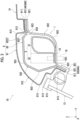
Fig. 1 is a plan view of a vehicle including a vehicle body structure (first embodiment) of the present invention. -
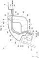
Fig. 2 is a view seen from a direction of arrow A inFig. 1 . -
Fig. 3 is a longitudinal sectional view taken along line B-B inFig. 2 . -
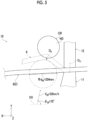
Fig. 4 is a plan view illustrating a state where an occupant protection test in the event of a pole side collision is performed on the vehicle illustrated inFig. 1 . -
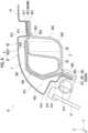
Fig. 5 is a plan view illustrating a state where an occupant protection test in the event of a pole side collision is performed on a vehicle in the related art. -
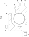
Fig. 6 is a view illustrating, in order, a process of manufacturing a reinforcement member provided in the vehicle body structure (first embodiment) of the present invention (cross-sectional view illustrating a die open state). -
Fig. 7 is a view illustrating, in order, the process of manufacturing the reinforcement member provided in the vehicle body structure (first embodiment) of the present invention (cross-sectional view illustrating a die clamped state). -
Fig. 8 is a cross-sectional view of a vehicle including a vehicle body structure (second embodiment) of the present invention. -
Fig. 9 is a cross-sectional view of a vehicle including a vehicle body structure (third embodiment) of the present invention. -
Fig. 10 is a cross-sectional view of a vehicle including a vehicle body structure (fourth embodiment) of the present invention. - Hereinafter, a vehicle body structure, a reinforcement member, and a reinforcement member manufacturing method of the present invention will be described in detail based on exemplary embodiments illustrated in the accompanying drawings.
-
Fig. 1 is a plan view of a vehicle including a vehicle body structure (first embodiment) of the present invention.Fig. 2 is a view seen from a direction of arrow A inFig. 1 .Fig. 3 is a longitudinal sectional view taken along line B-B inFig. 2 .Fig. 4 is a plan view illustrating a state where an occupant protection test in the event of a pole side collision is performed on the vehicle illustrated inFig. 1 .Fig. 5 is a plan view illustrating a state where an occupant protection test in the event of a pole side collision is performed on a vehicle in the related art.Fig. 6 is a view illustrating, in order, a process of manufacturing a reinforcement member provided in the vehicle body structure (first embodiment) of the present invention (cross-sectional view illustrating a die open state).Fig. 7 is a view illustrating, in order, the process of manufacturing the reinforcement member provided in the vehicle body structure (first embodiment) of the present invention (cross-sectional view illustrating a die clamped state). Incidentally, hereinafter, for convenience of description, a total length direction of an automotive vehicle is an X-axis direction, a vehicle width direction of the automotive vehicle is a Y-axis direction, and a vehicle height width direction of the automotive vehicle is a Z-axis direction. - As illustrated in
Figs. 1 and2 , anautomotive vehicle 10 includes a plurality of support members forming frames of a vehicle body, and the support member includes tworoof side rails 9, two center pillars (B pillars) 11, and oneroof reinforcement 12. - The
roof side rails 9 are beam members that are disposed on both left and right sides of theautomotive vehicle 10, respectively. - The
center pillars 11 are pillar members that are disposed at central portions on both the left and right sides of theautomotive vehicle 10, respectively. Thecenter pillar 11 is joined to theroof side rail 9. The joining method is not particularly limited, and for example, a welding method can be used. - The
roof reinforcement 12 is a beam member that is disposed across an upper portion of theautomotive vehicle 10 between the tworoof side rails 9. Theroof reinforcement 12 is also joined to theroof side rail 9. The joining method is not particularly limited, and for example, the same method as the method for joining thecenter pillar 11 and theroof side rail 9 can be used. - Incidentally, each of the
roof side rail 9, thecenter pillar 11, and theroof reinforcement 12 is made of, for example, a metal material such as aluminum. - In addition, in the present embodiment, a wagon-type automotive vehicle will be described as one example of the
automotive vehicle 10, but theautomotive vehicle 10 is not limited to the wagon-type automotive vehicle, and may be, for example, a sedan-type automotive vehicle, a truck, or the like. In addition, the present invention is also applicable to other vehicle bodies of theautomotive vehicle 10. - As illustrated in
Fig. 3 , theroof side rail 9 includes a side outer 91, a roof side inner 92, and a roof side outer 93, and is configured as a hollow body in which these members are joined to each other. - The side outer 91 is a member forming an outermost exterior of the
automotive vehicle 10. The side outer 91 is configured as a long plate member, and edge portions located on both sides in a width direction of the side outer 91 arejoints 911. Acentral portion 912 of the side outer 91 in the width direction, namely, thecentral portion 912 that is a portion between thejoints 911 includes adeformed portion 913 that is curved or bent and plastically deformed into a desired shape at a plurality of locations. In addition, the cross-sectional shape of thecentral portion 912 has a shape bulging toward the outside of theautomotive vehicle 10 as a whole. - The roof side inner 92 is a member forming an interior of the
automotive vehicle 10. The roof side inner 92 is also configured as a long plate member, and edge portions located on both sides in a width direction of the roof side inner 92 arejoints 921. Acentral portion 922 of the roof side inner 92 in the width direction, namely, thecentral portion 922 that is a portion between thejoints 921 includes adeformed portion 923 that is curved or bent and plastically deformed into a desired shape at a plurality of locations. In addition, the cross-sectional shape of thecentral portion 922 has a shape bulging toward the inside of theautomotive vehicle 10 as a whole. - The roof side outer 93 is a member located between the side outer 91 and the roof side inner 92. The roof side outer 93 is also configured as a long plate member, and edge portions located on both sides in a width direction of the roof side outer 93 are joint 931. A
central portion 932 of the roof side outer 93 in the width direction, namely, thecentral portion 932 that is a portion between thejoints 931 includes adeformed portion 933 that is curved or bent and plastically deformed into a desired shape at a plurality of locations. In addition, the cross-sectional shape of thecentral portion 932 has a shape bulging toward the outside of theautomotive vehicle 10 as a whole. - In the
roof side rail 9, thejoints 911 of the side outer 91, the joint 921 of the roof side inner 92, and the joint 931 of the roof side outer 93 are joined together in an overlapped state. The joining method is not particularly limited, for example, a welding method can be used, and particularly, it is preferable that spot welding is used. The plate members, namely, the joint 911, the joint 921, and the joint 931 can be quickly and easily joined together by using spot welding. Hereinafter, a portion in which the joint 911, the joint 921, and the joint 931 are collectively joined together is referred to as a "joint portion 94". - In the
roof side rail 9, onejoint portion 94A of twojoint portions 94 is located on adoor 13 side, and the otherjoint portion 94B is located on aroof panel 14 side. In addition, thejoint portion 94B is joined to a lower side (back side) of aroof panel 14. Spot welding can also be used as the joining method. - As illustrated in
Fig. 3 , areinforcement member 3 that reinforces theroof side rail 9 is disposed inside theroof side rail 9. Thereinforcement member 3 forms avehicle body structure 1, together with a roofside rail member 2 used as a part of theroof side rail 9. Hereinafter, thevehicle body structure 1 will be described. - The
vehicle body structure 1 includes the roofside rail member 2 and thereinforcement member 3 joined to the roofside rail member 2. - In the present embodiment, the roof
side rail member 2 to which thereinforcement member 3 is joined is the roof side inner 92 of the side outer 91, the roof side inner 92, and the roof side outer 93. Then, the roof side inner 92 is reinforced and has improved mechanical strength against external force by joining thereinforcement member 3 to the roof side inner 92. Particularly, when theautomotive vehicle 10 receives a collision from the side, the roof side rail 9 (roof side inner 92) is desired to have resistance against the impact of the collision. Therefore, thereinforcement member 3 has a function of improving the impact resistance of theroof side rail 9. - When the impact resistance of the
roof side rail 9 is evaluated, "an occupant protection test in the event of a pole side collision (hereinafter, simply referred to as an "occupant protection test")" set forth in Regulation No. 135 based on the AGREEMENT CONCERNING THE ADOPTION OF UNIFORM TECHNICAL PRESCRIPTIONS FOR WHEELED VEHICLES, EQUIPMENT AND PARTS is performed. As illustrated inFig. 4 , in the occupant protection test, for example, in the case of theautomotive vehicle 10 having a vehicle width of 1.5 m or less, a pole (impactor) 20 imitating a utility pole or the like collides toward a position where a head HD of an occupant CR riding on a front side of theautomotive vehicle 10 is assumed to be located. A collision angle θ20 at this time is 75° with respect to an axis OX parallel to the X-axis direction. A collision speed V20 is 32 km/h. In addition, a diameter ϕd20 of thepole 20 is 254 mm. - As illustrated in
Figs. 3 and4 , thereinforcement member 3 has a tubular shape, and is disposed along a longitudinal direction of the roof side inner 92 (roof side rail member 2) . As will be described later, thereinforcement member 3 is a shaped body, namely, a processed product that is formed by shaping one tubular body having a circular cross-sectional shape and serving as a base material 3' of thereinforcement member 3. Accordingly, the mechanical strength of thereinforcement member 3 itself is higher than that when thereinforcement member 3 is configured as, for example, a joined body in which a plurality of members are joined together. - Then, the
reinforcement member 3 that is a processed product from the base material 3' includes a pipe portion (ring-shaped portion) 31 having a non-circular cross-sectional ring shape, and aflange portion 32 protruding from an outer peripheral side of thepipe portion 31. - The
pipe portion 31 has a higher occupancy ratio (volume ratio) in thereinforcement member 3 than theflange portion 32. - The
flange portion 32 is a protruding piece that protrudes on an outer peripheral portion of thereinforcement member 3 and that is formed in a plate shape over the total length of thereinforcement member 3 along the longitudinal direction of the roof side inner 92. Theflange portion 32 is an overlap portion in which the base material 3' is crushed and parts of pipe walls of the base material 3' overlap each other. In addition, a protruding direction of theflange portion 32 faces an outer side surface of theautomotive vehicle 10, namely, a negative side in the Y-axis direction opposite to a collision direction of thepole 20. - The
flange portion 32 is joined to the roof side inner 92. The joining location is a location other than the joint 921 at which the roof side inner 92 (roof side rail member 2) is collectively joined to other members different from thereinforcement member 3, namely, to the side outer 91 and to the roof side outer 93, and is thecentral portion 922 in the present embodiment. - In addition, the
flange portion 32 is joined to the roofside rail member 2 by welding. Then, for example, spot welding can be used for the welding. Accordingly, before the roof side inner 92 and thereinforcement member 3 are assembled as a part of theautomotive vehicle 10, thecentral portion 922 of the roof side inner 92 and theflange portion 32 of thereinforcement member 3 can be quickly and easily joined together by applying a voltage to thecentral portion 922 of the roof side inner 92 and theflange portion 32 of thereinforcement member 3 that are sandwiched between apositive electrode 15 and a negative electrode 16 used for spot welding (refer to thepositive electrode 15 and the negative electrode 16 illustrated by two-dot chain lines inFig. 3 ). Incidentally, since thecentral portion 922 and theflange portion 32 form a laminated body of plate-shaped portions, spot welding can be performed thereon. - A comparison will be made between a case where the occupant protection test is performed on the roof side rail 9 (roof side inner 92) to which the
reinforcement member 3 configured as described above is joined (refer toFig. 4 ) and a case where the occupant protection test is performed on theroof side rail 9 in which thereinforcement member 3 is omitted (refer toFig. 5 ) . - As illustrated in
Fig. 4 , in the former case of the occupant protection test, a predetermined range AR9 that is linear along the longitudinal direction in theroof side rail 9 enters the inside of theautomotive vehicle 10 with a collision point O9 at the moment of collision of thepole 20 as an intermediate point, but the entering of theroof side rail 9 to the head HD of the occupant CR is prevented (state of theroof side rail 9 after the collision is illustrated by two-dot chain lines). Accordingly, the head HD of the occupant CR is protected. - On the other hand, as illustrated in
Fig. 5 , in the latter case of the occupant protection test, theroof side rail 9 is bent at the collision point O9, enters the inside of theautomotive vehicle 10, and reaches the head HD of the occupant CR (state of theroof side rail 9 after the collision is indicated by two-dot chain lines). - As described above, the
reinforcement member 3 is a member that prevents or suppresses unintentional bending of the roof side rail 9 (roof side rail member 2) to the inside of theautomotive vehicle 10 when the occupant protection test is performed. Accordingly, the head HD of the occupant CR can be protected in the event of a collision. Therefore, with a simple configuration in which thereinforcement member 3 including theflange portion 32 is joined to theroof side rail 9, theroof side rail 9 can be sufficiently reinforced, and thus the collision safety performance of theautomotive vehicle 10 is enhanced. - In addition, the
flange portion 32 is joined to the roof side inner 92 at a location other than locations where the roof side inner 92 (roof side rail member 2) is joined to other members different from thereinforcement member 3, namely, to the side outer 91 and to the roof side outer 93. Accordingly, the protruding direction of theflange portion 32 having a plate shape can face the outer side surface of theautomotive vehicle 10, namely, the negative side in the Y-axis direction opposite to the collision direction of thepole 20. Then, it is very difficult to bend theflange portion 32 having a plate shape at the collision point O9 in the width direction. Accordingly, the mechanical strength of thereinforcement member 3 is further improved, and it is possible to sufficiently prevent or suppress unintentional bending of theroof side rail 9 to the inside of theautomotive vehicle 10 in the event of a collision. - In addition, since the
flange portion 32 is jointed only to the roof side inner 92, spot welding can be used for the joining. In this case, spot welding is facilitated, and the state of joining between theflange portion 32 and the roof side inner 92 after welding can be firmly maintained for a long period of time. - As illustrated in
Fig. 4 , a part of thereinforcement member 3 overlaps an extension line O11 of thecenter pillar 11. Accordingly, it is possible to prevent theroof side rail 9 from being bent inward at theroof reinforcement 12 in the event of a collision (refer to theroof side rail 9 after the collision illustrated by two-dot chain lines inFig. 5 ), thereby contributing to the protection of the head HD of the occupant CR. Incidentally, the extension line O11 also overlaps theroof reinforcement 12. - In addition, a total length of the
reinforcement member 3 is shorter than a total length of the roof side inner 92 (roof side rail member 2). Accordingly, a portion that is desired to be reinforced in the roof side inner 92 can be intensively (preferentially) reinforced without excess or deficiency. - As described above, the
reinforcement member 3 is disposed inside theroof side rail 9. On the other hand, as an example where thereinforcement member 3 is disposed outside theroof side rail 9, when thereinforcement member 3 is disposed on an outer side of theautomotive vehicle 10, thereinforcement member 3 stands out and impairs the appearance of theautomotive vehicle 10, which is a concern. In addition, as another example where thereinforcement member 3 is disposed outside theroof side rail 9, when thereinforcement member 3 is disposed inside the automotive vehicle 10 (inside the vehicle), a comfort zone of theautomotive vehicle 10 becomes narrow, and the comfortability inside the vehicle is impaired, which is a concern. However, since thereinforcement member 3 is disposed inside theroof side rail 9, it is possible to prevent the appearance of theautomotive vehicle 10 from being impaired, or the comfortability from being impaired. - Incidentally, the
reinforcement member 3 is made of, for example, a metal material such as an Fe-C alloy. - Next, a method for manufacturing the
reinforcement member 3 will be described. In this manufacturing method, a shaping device 8 is used. - As illustrated in
Figs. 6 and7 , the shaping device 8 includes anupper die 81, alower die 82, agas supply unit 83, aheating unit 84, a coolingunit 85, adrive unit 86, and acontrol unit 87. - The
lower die 82 is fixed, and theupper die 81 is supported so as to be able to approach and separate from thelower die 82. As illustrated inFig. 6 , in the die open state of theupper die 81 and thelower die 82, the base material 3' can be disposed between theupper die 81 and thelower die 82. In addition, as illustrated inFig. 7 , in the die clamped state, theupper die 81 and thelower die 82 can define afirst cavity 88 forming thepipe portion 31 and asecond cavity 89 forming theflange portion 32. - The
gas supply unit 83 supplies high-pressure air into the base material 3'. Accordingly, the base material 3' can be prevented from excessively being crushed in the die clamped state. The configuration of thegas supply unit 83 is not particularly limited, and can be configured to include, for example, a compressor. - The
heating unit 84 heats the base material 3'. The configuration of theheating unit 84 is not particularly limited, and can be configured to include, for example, two electrodes that are electrically connected to the base material 3', and a voltage application unit that applies a voltage between the electrodes. Accordingly, the base material 3' can be softened by setting the base material 3' to an energized state and by heating the base material 3'. - The cooling
unit 85 rapidly cools the reinforcement member 3 (base material 3'). The configuration of the coolingunit 85 is not particularly limited, and can be configured to include, for example, a flow path which is provided in each of theupper die 81 and thelower die 82 and through which a refrigerant passes. Then, when the refrigerant passes through the flow paths, thereinforcement member 3 can be rapidly cooled on each of theupper die 81 and thelower die 82. Incidentally, the refrigerant may be either a liquid or a gas. - The
drive unit 86 enables theupper die 81 to approach and separate from thelower die 82 by moving theupper die 81. Accordingly, it is possible to switch between the die open state and the die clamped state. The configuration of thedrive unit 86 is not particularly limited, and can be configured to include, for example, a motor, a ball screw connected to the motor, and a linear guide connected to the ball screw. - The
control unit 87 controls operation of thegas supply unit 83, theheating unit 84, the coolingunit 85, and thedrive unit 86. The configuration of thecontrol unit 87 is not particularly limited, and can be configured to include, for example, a central processing unit (CPU) and various memories. - The shaping device 8 operates as follows.
- First, as illustrated in
Fig. 6 , theupper die 81 and thelower die 82 are set to the die open state, and the base material 3' is disposed between theupper die 81 and thelower die 82. - Next, the
heating unit 84 is operated in the die open state. Accordingly, the base material 3' can be softened. - Next, the
upper die 81 is approached to thelower die 82. This state does not reach the die clamped state illustrated inFig. 7 , and is a state where a gap is formed between theupper die 81 and thelower die 82. Then, thegas supply unit 83 is operated to perform primary blowing. Accordingly, a part of the base material 3' bulges and enters the gap between theupper die 81 and thelower die 82. - Next, in the die clamped state illustrated in
Fig. 7 , thegas supply unit 83 is operated to perform secondary blowing. Accordingly, the base material 3' can be deformed according to the shape of thereinforcement member 3, namely, thereinforcement member 3 including thepipe portion 31 and theflange portion 32 is formed. - Next, the cooling
unit 85 is operated to rapidly cool thereinforcement member 3. Accordingly, in thereinforcement member 3, austenite is transformed into martensite. - Next, the die open state is set again, and the
reinforcement member 3 is taken out. Thereafter, thereinforcement member 3 can be cut to a desired length and joined to the roofside rail member 2. -
Fig. 8 is a cross-sectional view of a vehicle including a vehicle body structure (second embodiment) of the present invention. - Hereinafter, a second embodiment of a vehicle body structure, a reinforcement member, and a reinforcement member manufacturing method of the present invention will be described with reference to the drawing, but the differences from the above-described embodiment will be mainly described, and a description of the same items will be omitted.
- The present embodiment is the same as the first embodiment except that a mating side to which the
reinforcement member 3 is joined is different. - As illustrated in
Fig. 8 , in thevehicle body structure 1 of the present embodiment, the roofside rail member 2 to which thereinforcement member 3 is joined is the roof side outer 93 of the side outer 91, the roof side inner 92, and the roof side outer 93. In this case, theflange portion 32 of thereinforcement member 3 is joined to thecentral portion 932 of the roof side outer 93. - In addition, the
reinforcement member 3 has a posture different from that of thereinforcement member 3 in the first embodiment, and is disposed upside down. Then, a protruding direction of theflange portion 32 of thereinforcement member 3 faces a positive side in the Y-axis direction. Accordingly, similarly to the first embodiment, it is very difficult to bend theflange portion 32 in the width direction, and thus the mechanical strength of thereinforcement member 3 is further improved, and it is possible to sufficiently prevent or suppress unintentional bending of theroof side rail 9 to the inside of theautomotive vehicle 10 in the event of a collision. Thevehicle body structure 1 described above has a configuration that is effective when thereinforcement member 3 is desired to be joined to the roof side outer 93. -
Fig. 9 is a cross-sectional view of a vehicle including a vehicle body structure (third embodiment) of the present invention. - Hereinafter, a third embodiment of a vehicle body structure, a reinforcement member, and a reinforcement member manufacturing method of the present invention will be described with reference to the drawing, but the differences from the above-described embodiment will be mainly described, and a description of the same items will be omitted.
- The present embodiment is the same as the first embodiment except that the configuration (shape) of the
reinforcement member 3 is different. - As illustrated in
Fig. 9 , in the present embodiment, thereinforcement member 3 includes twoflange portions 32. Theflange portions 32 are disposed on both sides of thepipe portion 31 via thepipe portion 31. - In addition, a protruding direction of one
flange portion 32A of the twoflange portions 32 faces the negative side in the Y-axis direction, and a protruding direction of theother flange portion 32B faces an upper side (positive side in the Z-axis direction). - Since the
reinforcement member 3 configured as described above includes the twoflange portions 32, the mechanical strength is more increased than thereinforcement member 3 of the first embodiment. Accordingly, the impact resistance of theroof side rail 9 can be further improved. -
Fig. 10 is a cross-sectional view of a vehicle including a vehicle body structure (fourth embodiment) of the present invention. - Hereinafter, a fourth embodiment of a vehicle body structure, a reinforcement member, and a reinforcement member manufacturing method of the present invention will be described with reference to the drawing, but the differences from the above-described embodiment will be mainly described, and a description of the same items will be omitted.
- The present embodiment is the same as the third embodiment except that a mating side to which the
reinforcement member 3 is joined is different. - As illustrated in
Fig. 10 , in thevehicle body structure 1 of the present embodiment, the roofside rail member 2 to which thereinforcement member 3 is joined is the roof side outer 93. - In addition, the
reinforcement member 3 has a posture different from that of thereinforcement member 3 of the third embodiment, and is disposed upside down. Then, the protruding direction of theflange portion 32A of thereinforcement member 3 faces the positive side in the Y-axis direction, and the protruding direction of theflange portion 32B faces a lower side (negative side in the Z-axis direction). - The
vehicle body structure 1 described above has a configuration that is effective when thereinforcement member 3 is desired to be joined to the roof side outer 93. - The vehicle body structure, the reinforcement member, and the reinforcement member manufacturing method of the present invention have been described above based on each of the illustrated embodiments, but the present invention is not limited thereto. In addition, each part forming the vehicle body structure or the reinforcement member can be replaced with any configuration capable of exhibiting the same function. In addition, any component may be added.
- In addition, the vehicle body structure, the reinforcement member, and the reinforcement member manufacturing method of the present invention may be a combination of any two or more configurations (features) in the above embodiments.
- In addition, the roof
side rail member 2 to which thereinforcement member 3 is joined is the roof side inner 92 in the first and third embodiments, and is the roof side outer 93 in the second and fourth embodiments, but is not limited thereto, and the side outer 91 may be used. - In addition, the
reinforcement member 3 is disposed inside theroof side rail 9, but is not limited thereto, and may be disposed outside theroof side rail 9. - In addition, the thickness of the
flange portion 32 can be appropriately adjusted by the shaping device 8. Accordingly, the joining location of theflange portion 32 can be, for example, between the roof side inner 92 and the roof side outer 93. -
- 10
- Automotive vehicle
- 1
- Vehicle body structure
- 2
- Roof side rail member
- 3
- Reinforcement member
- 3'
- Base material
- 31
- Pipe portion (ring-shaped portion)
- 32, 32A, 32B
- Flange portion
- 8
- Shaping device
- 81
- Upper die
- 82
- Lower die
- 83
- Gas supply unit
- 84
- Heating unit
- 85
- Cooling unit
- 86
- Drive unit
- 87
- Control unit
- 88
- First cavity
- 89
- Second cavity
- 9
- Roof side rail
- 91
- Side outer
- 911
- Joint
- 912
- Central portion
- 913
- Deformed portion
- 92
- Roof side Inner
- 921
- Joint
- 922
- Central portion
- 923
- Deformed portion
- 93
- Roof side outer
- 931
- Joint
- 932
- Central portion
- 933
- Deformed portion
- 94, 94A, 94B
- Joint portion
- 11
- Center pillar (B pillar)
- 12
- Roof reinforcement
- 13
- Door
- 14
- Roof panel
- 15
- Positive electrode
- 16
- Negative electrode
- 20
- Pole (impactor)
- AR9
- Range
- CR
- Occupant
- ϕd20
- Diameter
- HD
- Head
- OX
- Axis
- O9
- Collision point
- O11
- Extension line
- V20
- Collision speed
- θ20
- Collision angle
Claims (10)
- A vehicle body structure (1) comprising:a roof side rail member (2) used as one of support members of a vehicle body (10); anda reinforcement member (3) disposed along a longitudinal direction of the roof side rail member (2) to reinforce the roof side rail member (2),characterized in thatthe reinforcement member (3) is a processed product formed by shaping a tubular body, and includes a flange portion (32, 32A, 32B) that protrudes on an outer peripheral portion and that is formed in the longitudinal direction of the roof side rail member (2),the flange portion (32, 32A, 32B) is an overlap portion in which a base material (3') of the reinforcement member (3) is crushed and parts of pipe walls of the base material (3') overlap each other, andthe flange portion (32, 32A, 32B) is joined to the roof side rail member (2).
- The vehicle body structure (1) according to claim 1,wherein the vehicle body (10) includes a roof side rail (9) configured as a hollow body including a side outer (91) forming an outermost exterior of the vehicle body (10), a roof side inner (92) forming an interior of the vehicle body (10), and a roof side outer (93) located between the side outer (91) and the roof side inner (92), andthe roof side rail member (2) is one of the side outer (91), the roof side inner (92), and the roof side outer (93).
- The vehicle body structure (1) according to claim 1 or 2,
wherein the flange portion (32, 32A, 32B) faces an outer side surface of the vehicle body (10). - The vehicle body structure (1) according to any one of claims 1 to 3,wherein the roof side rail member (2) is joined to a pillar member (11) that is one of the support members, anda part of the reinforcement member (3) overlaps an extension line of the pillar member (11).
- The vehicle body structure (1) according to claim 4,
wherein a total length of the reinforcement member (3) is shorter than a total length of the roof side rail member (2) . - The vehicle body structure (1) according to any one of claims 1 to 5,
wherein the reinforcement member (3) prevents or suppresses bending of the roof side rail member (2) to an inside of the vehicle body (10) when an occupant protection test set forth in Regulation No. 135 of an AGREEMENT CONCERNING THE ADOPTION OF UNIFORM TECHNICAL PRESCRIPTIONS FOR WHEELED VEHICLES, EQUIPMENT AND PARTS in an event of a pole side collision is performed. - The vehicle body structure (1) according to any one of claims 1 to 6,
wherein the flange portion (32, 32A, 32B) is joined to the roof side rail member (2) by welding. - The vehicle body structure (1) according to claim 7,
wherein the welding is spot welding. - The vehicle body structure (1) according to claim 1,
wherein the flange portion (32, 32A, 32B) is joined to the roof side rail member (2) at a location other than locations where the roof side rail member (2) is joined to other members different from the reinforcement member (3). - A method for manufacturing the reinforcement member (3) according to claim 1, the method comprising:
shaping a tubular body having a circular cross-sectional shape and serving as the base material (3') of the reinforcement member (3) by applying a force to the tubular body from an outside and an inside, to form a pipe portion (31) having a non-circular cross-sectional shape and a flange portion (32, 32A, 32B) protruding from an outer peripheral side of the pipe portion (31).
Applications Claiming Priority (2)
| Application Number | Priority Date | Filing Date | Title |
|---|---|---|---|
| JP2019226632A JP7384655B2 (en) | 2019-12-16 | 2019-12-16 | Vehicle body structure, reinforcing member, and method for manufacturing reinforcing member |
| PCT/JP2020/045850 WO2021125015A1 (en) | 2019-12-16 | 2020-12-09 | Vehicle body structure, reinforcing member, and method for manufacturing reinforcing member |
Publications (3)
| Publication Number | Publication Date |
|---|---|
| EP4079608A1 EP4079608A1 (en) | 2022-10-26 |
| EP4079608A4 EP4079608A4 (en) | 2023-02-08 |
| EP4079608B1 true EP4079608B1 (en) | 2025-04-02 |
Family
ID=76431999
Family Applications (1)
| Application Number | Title | Priority Date | Filing Date |
|---|---|---|---|
| EP20901331.7A Active EP4079608B1 (en) | 2019-12-16 | 2020-12-09 | Vehicle body structure, reinforcing member, and method for manufacturing reinforcing member |
Country Status (8)
| Country | Link |
|---|---|
| US (1) | US11919573B2 (en) |
| EP (1) | EP4079608B1 (en) |
| JP (1) | JP7384655B2 (en) |
| KR (1) | KR102891095B1 (en) |
| CN (1) | CN114466782B (en) |
| CA (1) | CA3156485C (en) |
| ES (1) | ES3028107T3 (en) |
| WO (1) | WO2021125015A1 (en) |
Families Citing this family (2)
| Publication number | Priority date | Publication date | Assignee | Title |
|---|---|---|---|---|
| DE102022211491A1 (en) * | 2022-10-28 | 2024-05-08 | Volkswagen Aktiengesellschaft | Trailer, trailer assembly and motor vehicle |
| WO2024187109A2 (en) * | 2023-03-09 | 2024-09-12 | Magna International Inc. | B-pillarless body side structure for a vehicle |
Family Cites Families (27)
| Publication number | Priority date | Publication date | Assignee | Title |
|---|---|---|---|---|
| US4045075A (en) * | 1975-12-18 | 1977-08-30 | Pulver Donald W | Automobile body frame and envelope construction |
| JPS59206272A (en) * | 1983-05-07 | 1984-11-22 | 本田技研工業株式会社 | Structural material |
| AU618374B2 (en) * | 1988-06-30 | 1991-12-19 | General Motors-Holden's Automotive Limited | Vehicle body and method of manufacture |
| NO165284C (en) * | 1988-09-09 | 1991-01-23 | Norsk Hydro As | PROCEDURE FOR MANUFACTURING THE BODY FRAME AND THE BODY FRAME. |
| US5070717A (en) * | 1991-01-22 | 1991-12-10 | General Motors Corporation | Method of forming a tubular member with flange |
| JP2890979B2 (en) * | 1992-06-22 | 1999-05-17 | 日産自動車株式会社 | Coupling structure of body frame members |
| BR9714374A (en) * | 1996-12-03 | 2000-03-21 | Elpatronic Ag | Process for manufacturing a profiled part |
| JP3489495B2 (en) * | 1998-07-22 | 2004-01-19 | トヨタ自動車株式会社 | Impact energy absorbing structure on the upper part of the vehicle |
| JP3498614B2 (en) * | 1999-01-29 | 2004-02-16 | マツダ株式会社 | Vehicle body structure |
| JP3972521B2 (en) * | 1999-06-30 | 2007-09-05 | いすゞ自動車株式会社 | Vehicle pillar structure |
| JP4368022B2 (en) * | 2000-01-21 | 2009-11-18 | 富士重工業株式会社 | Body member joining structure and joining method |
| JP4617562B2 (en) * | 2000-11-06 | 2011-01-26 | マツダ株式会社 | Upper body structure of the vehicle |
| JP3830401B2 (en) * | 2001-06-04 | 2006-10-04 | 株式会社丸順 | Structure around the vehicle door opening |
| JP4033658B2 (en) * | 2001-10-10 | 2008-01-16 | アスカ株式会社 | Body structure |
| JP3832381B2 (en) * | 2002-05-01 | 2006-10-11 | 日産自動車株式会社 | Preliminary molded product and hollow molded product hydraulic forming method and automobile body structure member |
| US6739166B1 (en) * | 2002-12-17 | 2004-05-25 | General Motors Corporation | Method of forming tubular member with flange |
| DE10350145B4 (en) * | 2003-10-28 | 2006-04-13 | Daimlerchrysler Ag | Generation of hydroformed components with flange |
| JP4736905B2 (en) * | 2006-03-31 | 2011-07-27 | トヨタ自動車株式会社 | Vehicle center pillar reinforcement structure |
| DE102006014962A1 (en) * | 2006-03-31 | 2007-10-04 | Dr.Ing.H.C. F. Porsche Ag | Sill reinforcement element for a vehicle body |
| US7543883B2 (en) * | 2006-10-11 | 2009-06-09 | Ford Global Technologies, Llc | Roof rail with integrally formed pinched flanges |
| US8409725B2 (en) * | 2007-03-28 | 2013-04-02 | Kobe Steel, Ltd. | Structural member of different materials |
| EP2305539B1 (en) * | 2008-07-04 | 2013-05-15 | Honda Motor Co., Ltd. | Front pillar for automobile |
| US8662567B2 (en) * | 2009-02-02 | 2014-03-04 | Vari-Form, Inc. | Vehicle roof support pillar assembly |
| KR101637774B1 (en) * | 2014-12-11 | 2016-07-08 | 현대자동차주식회사 | A front pillar with integral flanges |
| US9187135B1 (en) * | 2015-01-09 | 2015-11-17 | Nissan North America, Inc. | Vehicle body structure |
| JP2016159813A (en) * | 2015-03-03 | 2016-09-05 | トヨタ自動車株式会社 | Vehicle skeleton structure |
| JP6969429B2 (en) * | 2018-02-20 | 2021-11-24 | トヨタ自動車株式会社 | Vehicle side structure |
-
2019
- 2019-12-16 JP JP2019226632A patent/JP7384655B2/en active Active
-
2020
- 2020-12-09 EP EP20901331.7A patent/EP4079608B1/en active Active
- 2020-12-09 CN CN202080065579.3A patent/CN114466782B/en active Active
- 2020-12-09 CA CA3156485A patent/CA3156485C/en active Active
- 2020-12-09 KR KR1020227008337A patent/KR102891095B1/en active Active
- 2020-12-09 WO PCT/JP2020/045850 patent/WO2021125015A1/en not_active Ceased
- 2020-12-09 ES ES20901331T patent/ES3028107T3/en active Active
-
2022
- 2022-05-27 US US17/827,248 patent/US11919573B2/en active Active
Also Published As
| Publication number | Publication date |
|---|---|
| WO2021125015A1 (en) | 2021-06-24 |
| KR20220110474A (en) | 2022-08-08 |
| CA3156485C (en) | 2025-06-17 |
| CA3156485A1 (en) | 2021-06-24 |
| KR102891095B1 (en) | 2025-11-24 |
| JP2021094968A (en) | 2021-06-24 |
| CN114466782A (en) | 2022-05-10 |
| US20220289296A1 (en) | 2022-09-15 |
| CN114466782B (en) | 2025-02-18 |
| EP4079608A4 (en) | 2023-02-08 |
| EP4079608A1 (en) | 2022-10-26 |
| JP7384655B2 (en) | 2023-11-21 |
| US11919573B2 (en) | 2024-03-05 |
| ES3028107T3 (en) | 2025-06-18 |
Similar Documents
| Publication | Publication Date | Title |
|---|---|---|
| US20230234645A1 (en) | Body side structural frame of a vehicle | |
| US8276954B2 (en) | Bumper system | |
| KR20160021045A (en) | Structural component and method for manufacturing a structural component | |
| US7331626B2 (en) | Vehicle body structure reinforced against side impact | |
| JP4119362B2 (en) | Method and apparatus for manufacturing automotive beams | |
| US20140232138A1 (en) | Vehicle body side portion structure | |
| US9180759B2 (en) | Impact beam | |
| US11919573B2 (en) | Vehicle body structure, reinforcement member, and reinforcement member manufacturing method | |
| EP4396042A1 (en) | Multi-tubular beam with forged weld seam | |
| CN108290610B (en) | Structural beam with cover plate and method of manufacture | |
| US12319215B2 (en) | Vehicle structure | |
| CN108367785B (en) | Hardened UHSS structural beam with stiffeners and method of manufacture | |
| CN120457069A (en) | Integral roof ring for vehicle frame | |
| US20140062132A1 (en) | Impact Beam | |
| US10967713B2 (en) | Vehicle side door | |
| JP7350610B2 (en) | Vehicle bumper, bumper member, and method for manufacturing bumper member | |
| JP2015071365A (en) | Reinforcement structure for side door for automobile |
Legal Events
| Date | Code | Title | Description |
|---|---|---|---|
| STAA | Information on the status of an ep patent application or granted ep patent |
Free format text: STATUS: THE INTERNATIONAL PUBLICATION HAS BEEN MADE |
|
| PUAI | Public reference made under article 153(3) epc to a published international application that has entered the european phase |
Free format text: ORIGINAL CODE: 0009012 |
|
| STAA | Information on the status of an ep patent application or granted ep patent |
Free format text: STATUS: REQUEST FOR EXAMINATION WAS MADE |
|
| 17P | Request for examination filed |
Effective date: 20220324 |
|
| AK | Designated contracting states |
Kind code of ref document: A1 Designated state(s): AL AT BE BG CH CY CZ DE DK EE ES FI FR GB GR HR HU IE IS IT LI LT LU LV MC MK MT NL NO PL PT RO RS SE SI SK SM TR |
|
| STAA | Information on the status of an ep patent application or granted ep patent |
Free format text: STATUS: EXAMINATION IS IN PROGRESS |
|
| A4 | Supplementary search report drawn up and despatched |
Effective date: 20230112 |
|
| RIC1 | Information provided on ipc code assigned before grant |
Ipc: B62D 25/06 19680901ALI20230105BHEP Ipc: B62D 25/04 19680901AFI20230105BHEP |
|
| 17Q | First examination report despatched |
Effective date: 20230126 |
|
| DAV | Request for validation of the european patent (deleted) | ||
| DAX | Request for extension of the european patent (deleted) | ||
| GRAP | Despatch of communication of intention to grant a patent |
Free format text: ORIGINAL CODE: EPIDOSNIGR1 |
|
| STAA | Information on the status of an ep patent application or granted ep patent |
Free format text: STATUS: GRANT OF PATENT IS INTENDED |
|
| INTG | Intention to grant announced |
Effective date: 20241021 |
|
| GRAS | Grant fee paid |
Free format text: ORIGINAL CODE: EPIDOSNIGR3 |
|
| GRAA | (expected) grant |
Free format text: ORIGINAL CODE: 0009210 |
|
| STAA | Information on the status of an ep patent application or granted ep patent |
Free format text: STATUS: THE PATENT HAS BEEN GRANTED |
|
| AK | Designated contracting states |
Kind code of ref document: B1 Designated state(s): AL AT BE BG CH CY CZ DE DK EE ES FI FR GB GR HR HU IE IS IT LI LT LU LV MC MK MT NL NO PL PT RO RS SE SI SK SM TR |
|
| REG | Reference to a national code |
Ref country code: GB Ref legal event code: FG4D |
|
| REG | Reference to a national code |
Ref country code: CH Ref legal event code: EP |
|
| REG | Reference to a national code |
Ref country code: DE Ref legal event code: R096 Ref document number: 602020048914 Country of ref document: DE |
|
| REG | Reference to a national code |
Ref country code: IE Ref legal event code: FG4D |
|
| REG | Reference to a national code |
Ref country code: ES Ref legal event code: FG2A Ref document number: 3028107 Country of ref document: ES Kind code of ref document: T3 Effective date: 20250618 |
|
| REG | Reference to a national code |
Ref country code: NL Ref legal event code: MP Effective date: 20250402 |
|
| PG25 | Lapsed in a contracting state [announced via postgrant information from national office to epo] |
Ref country code: NL Free format text: LAPSE BECAUSE OF FAILURE TO SUBMIT A TRANSLATION OF THE DESCRIPTION OR TO PAY THE FEE WITHIN THE PRESCRIBED TIME-LIMIT Effective date: 20250402 |
|
| REG | Reference to a national code |
Ref country code: AT Ref legal event code: MK05 Ref document number: 1781064 Country of ref document: AT Kind code of ref document: T Effective date: 20250402 |
|
| PG25 | Lapsed in a contracting state [announced via postgrant information from national office to epo] |
Ref country code: FI Free format text: LAPSE BECAUSE OF FAILURE TO SUBMIT A TRANSLATION OF THE DESCRIPTION OR TO PAY THE FEE WITHIN THE PRESCRIBED TIME-LIMIT Effective date: 20250402 Ref country code: PT Free format text: LAPSE BECAUSE OF FAILURE TO SUBMIT A TRANSLATION OF THE DESCRIPTION OR TO PAY THE FEE WITHIN THE PRESCRIBED TIME-LIMIT Effective date: 20250804 |
|
| REG | Reference to a national code |
Ref country code: LT Ref legal event code: MG9D |
|
| PG25 | Lapsed in a contracting state [announced via postgrant information from national office to epo] |
Ref country code: NO Free format text: LAPSE BECAUSE OF FAILURE TO SUBMIT A TRANSLATION OF THE DESCRIPTION OR TO PAY THE FEE WITHIN THE PRESCRIBED TIME-LIMIT Effective date: 20250702 Ref country code: GR Free format text: LAPSE BECAUSE OF FAILURE TO SUBMIT A TRANSLATION OF THE DESCRIPTION OR TO PAY THE FEE WITHIN THE PRESCRIBED TIME-LIMIT Effective date: 20250703 |
|
| PG25 | Lapsed in a contracting state [announced via postgrant information from national office to epo] |
Ref country code: PL Free format text: LAPSE BECAUSE OF FAILURE TO SUBMIT A TRANSLATION OF THE DESCRIPTION OR TO PAY THE FEE WITHIN THE PRESCRIBED TIME-LIMIT Effective date: 20250402 |
|
| PG25 | Lapsed in a contracting state [announced via postgrant information from national office to epo] |
Ref country code: BG Free format text: LAPSE BECAUSE OF FAILURE TO SUBMIT A TRANSLATION OF THE DESCRIPTION OR TO PAY THE FEE WITHIN THE PRESCRIBED TIME-LIMIT Effective date: 20250402 |
|
| PG25 | Lapsed in a contracting state [announced via postgrant information from national office to epo] |
Ref country code: HR Free format text: LAPSE BECAUSE OF FAILURE TO SUBMIT A TRANSLATION OF THE DESCRIPTION OR TO PAY THE FEE WITHIN THE PRESCRIBED TIME-LIMIT Effective date: 20250402 |
|
| PG25 | Lapsed in a contracting state [announced via postgrant information from national office to epo] |
Ref country code: AT Free format text: LAPSE BECAUSE OF FAILURE TO SUBMIT A TRANSLATION OF THE DESCRIPTION OR TO PAY THE FEE WITHIN THE PRESCRIBED TIME-LIMIT Effective date: 20250402 |
|
| PG25 | Lapsed in a contracting state [announced via postgrant information from national office to epo] |
Ref country code: RS Free format text: LAPSE BECAUSE OF FAILURE TO SUBMIT A TRANSLATION OF THE DESCRIPTION OR TO PAY THE FEE WITHIN THE PRESCRIBED TIME-LIMIT Effective date: 20250702 |
|
| PG25 | Lapsed in a contracting state [announced via postgrant information from national office to epo] |
Ref country code: IS Free format text: LAPSE BECAUSE OF FAILURE TO SUBMIT A TRANSLATION OF THE DESCRIPTION OR TO PAY THE FEE WITHIN THE PRESCRIBED TIME-LIMIT Effective date: 20250802 |
|
| PG25 | Lapsed in a contracting state [announced via postgrant information from national office to epo] |
Ref country code: LV Free format text: LAPSE BECAUSE OF FAILURE TO SUBMIT A TRANSLATION OF THE DESCRIPTION OR TO PAY THE FEE WITHIN THE PRESCRIBED TIME-LIMIT Effective date: 20250402 |
|
| REG | Reference to a national code |
Ref country code: DE Ref legal event code: R097 Ref document number: 602020048914 Country of ref document: DE |
|
| PGFP | Annual fee paid to national office [announced via postgrant information from national office to epo] |
Ref country code: DE Payment date: 20251028 Year of fee payment: 6 |
|
| PGFP | Annual fee paid to national office [announced via postgrant information from national office to epo] |
Ref country code: GB Payment date: 20251030 Year of fee payment: 6 |
|
| PG25 | Lapsed in a contracting state [announced via postgrant information from national office to epo] |
Ref country code: DK Free format text: LAPSE BECAUSE OF FAILURE TO SUBMIT A TRANSLATION OF THE DESCRIPTION OR TO PAY THE FEE WITHIN THE PRESCRIBED TIME-LIMIT Effective date: 20250402 Ref country code: SM Free format text: LAPSE BECAUSE OF FAILURE TO SUBMIT A TRANSLATION OF THE DESCRIPTION OR TO PAY THE FEE WITHIN THE PRESCRIBED TIME-LIMIT Effective date: 20250402 |
|
| PG25 | Lapsed in a contracting state [announced via postgrant information from national office to epo] |
Ref country code: CZ Free format text: LAPSE BECAUSE OF FAILURE TO SUBMIT A TRANSLATION OF THE DESCRIPTION OR TO PAY THE FEE WITHIN THE PRESCRIBED TIME-LIMIT Effective date: 20250402 |
|
| PG25 | Lapsed in a contracting state [announced via postgrant information from national office to epo] |
Ref country code: EE Free format text: LAPSE BECAUSE OF FAILURE TO SUBMIT A TRANSLATION OF THE DESCRIPTION OR TO PAY THE FEE WITHIN THE PRESCRIBED TIME-LIMIT Effective date: 20250402 |
|
| PG25 | Lapsed in a contracting state [announced via postgrant information from national office to epo] |
Ref country code: SK Free format text: LAPSE BECAUSE OF FAILURE TO SUBMIT A TRANSLATION OF THE DESCRIPTION OR TO PAY THE FEE WITHIN THE PRESCRIBED TIME-LIMIT Effective date: 20250402 |
|
| PG25 | Lapsed in a contracting state [announced via postgrant information from national office to epo] |
Ref country code: IT Free format text: LAPSE BECAUSE OF FAILURE TO SUBMIT A TRANSLATION OF THE DESCRIPTION OR TO PAY THE FEE WITHIN THE PRESCRIBED TIME-LIMIT Effective date: 20250402 |
|
| PLBE | No opposition filed within time limit |
Free format text: ORIGINAL CODE: 0009261 |
|
| STAA | Information on the status of an ep patent application or granted ep patent |
Free format text: STATUS: NO OPPOSITION FILED WITHIN TIME LIMIT |
|
| PG25 | Lapsed in a contracting state [announced via postgrant information from national office to epo] |
Ref country code: RO Free format text: LAPSE BECAUSE OF FAILURE TO SUBMIT A TRANSLATION OF THE DESCRIPTION OR TO PAY THE FEE WITHIN THE PRESCRIBED TIME-LIMIT Effective date: 20250402 |
|
| REG | Reference to a national code |
Ref country code: CH Ref legal event code: L10 Free format text: ST27 STATUS EVENT CODE: U-0-0-L10-L00 (AS PROVIDED BY THE NATIONAL OFFICE) Effective date: 20260211 |
|
| 26N | No opposition filed |
Effective date: 20260105 |
|
| PGFP | Annual fee paid to national office [announced via postgrant information from national office to epo] |
Ref country code: ES Payment date: 20260108 Year of fee payment: 6 |