EP4079549A1 - A method for controlling a refrigeration system of a vehicle - Google Patents
A method for controlling a refrigeration system of a vehicle Download PDFInfo
- Publication number
- EP4079549A1 EP4079549A1 EP21169690.1A EP21169690A EP4079549A1 EP 4079549 A1 EP4079549 A1 EP 4079549A1 EP 21169690 A EP21169690 A EP 21169690A EP 4079549 A1 EP4079549 A1 EP 4079549A1
- Authority
- EP
- European Patent Office
- Prior art keywords
- expansion valve
- temperature
- refrigerant
- evaporator
- secondary fluid
- Prior art date
- Legal status (The legal status is an assumption and is not a legal conclusion. Google has not performed a legal analysis and makes no representation as to the accuracy of the status listed.)
- Granted
Links
Images
Classifications
-
- B—PERFORMING OPERATIONS; TRANSPORTING
- B60—VEHICLES IN GENERAL
- B60H—ARRANGEMENTS OF HEATING, COOLING, VENTILATING OR OTHER AIR-TREATING DEVICES SPECIALLY ADAPTED FOR PASSENGER OR GOODS SPACES OF VEHICLES
- B60H1/00—Heating, cooling or ventilating devices
- B60H1/32—Cooling devices
- B60H1/3204—Cooling devices using compression
- B60H1/323—Cooling devices using compression characterised by comprising auxiliary or multiple systems, e.g. plurality of evaporators, or by involving auxiliary cooling devices
-
- B—PERFORMING OPERATIONS; TRANSPORTING
- B60—VEHICLES IN GENERAL
- B60H—ARRANGEMENTS OF HEATING, COOLING, VENTILATING OR OTHER AIR-TREATING DEVICES SPECIALLY ADAPTED FOR PASSENGER OR GOODS SPACES OF VEHICLES
- B60H1/00—Heating, cooling or ventilating devices
- B60H1/32—Cooling devices
- B60H1/3204—Cooling devices using compression
- B60H1/3205—Control means therefor
- B60H1/3207—Control means therefor for minimizing the humidity of the air
-
- B—PERFORMING OPERATIONS; TRANSPORTING
- B60—VEHICLES IN GENERAL
- B60H—ARRANGEMENTS OF HEATING, COOLING, VENTILATING OR OTHER AIR-TREATING DEVICES SPECIALLY ADAPTED FOR PASSENGER OR GOODS SPACES OF VEHICLES
- B60H1/00—Heating, cooling or ventilating devices
- B60H1/32—Cooling devices
- B60H1/3204—Cooling devices using compression
- B60H1/3205—Control means therefor
- B60H1/3211—Control means therefor for increasing the efficiency of a vehicle refrigeration cycle
-
- B—PERFORMING OPERATIONS; TRANSPORTING
- B60—VEHICLES IN GENERAL
- B60H—ARRANGEMENTS OF HEATING, COOLING, VENTILATING OR OTHER AIR-TREATING DEVICES SPECIALLY ADAPTED FOR PASSENGER OR GOODS SPACES OF VEHICLES
- B60H1/00—Heating, cooling or ventilating devices
- B60H1/32—Cooling devices
- B60H1/3204—Cooling devices using compression
- B60H1/3228—Cooling devices using compression characterised by refrigerant circuit configurations
- B60H1/32281—Cooling devices using compression characterised by refrigerant circuit configurations comprising a single secondary circuit, e.g. at evaporator or condenser side
-
- F—MECHANICAL ENGINEERING; LIGHTING; HEATING; WEAPONS; BLASTING
- F25—REFRIGERATION OR COOLING; COMBINED HEATING AND REFRIGERATION SYSTEMS; HEAT PUMP SYSTEMS; MANUFACTURE OR STORAGE OF ICE; LIQUEFACTION SOLIDIFICATION OF GASES
- F25B—REFRIGERATION MACHINES, PLANTS OR SYSTEMS; COMBINED HEATING AND REFRIGERATION SYSTEMS; HEAT PUMP SYSTEMS
- F25B49/00—Arrangement or mounting of control or safety devices
- F25B49/02—Arrangement or mounting of control or safety devices for compression type machines, plants or systems
-
- F—MECHANICAL ENGINEERING; LIGHTING; HEATING; WEAPONS; BLASTING
- F25—REFRIGERATION OR COOLING; COMBINED HEATING AND REFRIGERATION SYSTEMS; HEAT PUMP SYSTEMS; MANUFACTURE OR STORAGE OF ICE; LIQUEFACTION SOLIDIFICATION OF GASES
- F25B—REFRIGERATION MACHINES, PLANTS OR SYSTEMS; COMBINED HEATING AND REFRIGERATION SYSTEMS; HEAT PUMP SYSTEMS
- F25B5/00—Compression machines, plants or systems, with several evaporator circuits, e.g. for varying refrigerating capacity
- F25B5/02—Compression machines, plants or systems, with several evaporator circuits, e.g. for varying refrigerating capacity arranged in parallel
-
- B—PERFORMING OPERATIONS; TRANSPORTING
- B60—VEHICLES IN GENERAL
- B60H—ARRANGEMENTS OF HEATING, COOLING, VENTILATING OR OTHER AIR-TREATING DEVICES SPECIALLY ADAPTED FOR PASSENGER OR GOODS SPACES OF VEHICLES
- B60H1/00—Heating, cooling or ventilating devices
- B60H1/00271—HVAC devices specially adapted for particular vehicle parts or components and being connected to the vehicle HVAC unit
- B60H1/00278—HVAC devices specially adapted for particular vehicle parts or components and being connected to the vehicle HVAC unit for the battery
-
- B—PERFORMING OPERATIONS; TRANSPORTING
- B60—VEHICLES IN GENERAL
- B60H—ARRANGEMENTS OF HEATING, COOLING, VENTILATING OR OTHER AIR-TREATING DEVICES SPECIALLY ADAPTED FOR PASSENGER OR GOODS SPACES OF VEHICLES
- B60H1/00—Heating, cooling or ventilating devices
- B60H1/32—Cooling devices
- B60H2001/3236—Cooling devices information from a variable is obtained
- B60H2001/3248—Cooling devices information from a variable is obtained related to pressure
- B60H2001/325—Cooling devices information from a variable is obtained related to pressure of the refrigerant at a compressing unit
-
- B—PERFORMING OPERATIONS; TRANSPORTING
- B60—VEHICLES IN GENERAL
- B60H—ARRANGEMENTS OF HEATING, COOLING, VENTILATING OR OTHER AIR-TREATING DEVICES SPECIALLY ADAPTED FOR PASSENGER OR GOODS SPACES OF VEHICLES
- B60H1/00—Heating, cooling or ventilating devices
- B60H1/32—Cooling devices
- B60H2001/3236—Cooling devices information from a variable is obtained
- B60H2001/3248—Cooling devices information from a variable is obtained related to pressure
- B60H2001/3252—Cooling devices information from a variable is obtained related to pressure of the refrigerant at an evaporating unit
-
- B—PERFORMING OPERATIONS; TRANSPORTING
- B60—VEHICLES IN GENERAL
- B60H—ARRANGEMENTS OF HEATING, COOLING, VENTILATING OR OTHER AIR-TREATING DEVICES SPECIALLY ADAPTED FOR PASSENGER OR GOODS SPACES OF VEHICLES
- B60H1/00—Heating, cooling or ventilating devices
- B60H1/32—Cooling devices
- B60H2001/3236—Cooling devices information from a variable is obtained
- B60H2001/3255—Cooling devices information from a variable is obtained related to temperature
- B60H2001/3257—Cooling devices information from a variable is obtained related to temperature of the refrigerant at a compressing unit
-
- B—PERFORMING OPERATIONS; TRANSPORTING
- B60—VEHICLES IN GENERAL
- B60H—ARRANGEMENTS OF HEATING, COOLING, VENTILATING OR OTHER AIR-TREATING DEVICES SPECIALLY ADAPTED FOR PASSENGER OR GOODS SPACES OF VEHICLES
- B60H1/00—Heating, cooling or ventilating devices
- B60H1/32—Cooling devices
- B60H2001/3236—Cooling devices information from a variable is obtained
- B60H2001/3255—Cooling devices information from a variable is obtained related to temperature
- B60H2001/3263—Cooling devices information from a variable is obtained related to temperature of the refrigerant at an evaporating unit
-
- B—PERFORMING OPERATIONS; TRANSPORTING
- B60—VEHICLES IN GENERAL
- B60H—ARRANGEMENTS OF HEATING, COOLING, VENTILATING OR OTHER AIR-TREATING DEVICES SPECIALLY ADAPTED FOR PASSENGER OR GOODS SPACES OF VEHICLES
- B60H1/00—Heating, cooling or ventilating devices
- B60H1/32—Cooling devices
- B60H2001/3269—Cooling devices output of a control signal
- B60H2001/3285—Cooling devices output of a control signal related to an expansion unit
-
- F—MECHANICAL ENGINEERING; LIGHTING; HEATING; WEAPONS; BLASTING
- F25—REFRIGERATION OR COOLING; COMBINED HEATING AND REFRIGERATION SYSTEMS; HEAT PUMP SYSTEMS; MANUFACTURE OR STORAGE OF ICE; LIQUEFACTION SOLIDIFICATION OF GASES
- F25B—REFRIGERATION MACHINES, PLANTS OR SYSTEMS; COMBINED HEATING AND REFRIGERATION SYSTEMS; HEAT PUMP SYSTEMS
- F25B2600/00—Control issues
- F25B2600/25—Control of valves
- F25B2600/2513—Expansion valves
-
- F—MECHANICAL ENGINEERING; LIGHTING; HEATING; WEAPONS; BLASTING
- F25—REFRIGERATION OR COOLING; COMBINED HEATING AND REFRIGERATION SYSTEMS; HEAT PUMP SYSTEMS; MANUFACTURE OR STORAGE OF ICE; LIQUEFACTION SOLIDIFICATION OF GASES
- F25B—REFRIGERATION MACHINES, PLANTS OR SYSTEMS; COMBINED HEATING AND REFRIGERATION SYSTEMS; HEAT PUMP SYSTEMS
- F25B2700/00—Sensing or detecting of parameters; Sensors therefor
- F25B2700/21—Temperatures
- F25B2700/2115—Temperatures of a compressor or the drive means therefor
- F25B2700/21151—Temperatures of a compressor or the drive means therefor at the suction side of the compressor
-
- F—MECHANICAL ENGINEERING; LIGHTING; HEATING; WEAPONS; BLASTING
- F25—REFRIGERATION OR COOLING; COMBINED HEATING AND REFRIGERATION SYSTEMS; HEAT PUMP SYSTEMS; MANUFACTURE OR STORAGE OF ICE; LIQUEFACTION SOLIDIFICATION OF GASES
- F25B—REFRIGERATION MACHINES, PLANTS OR SYSTEMS; COMBINED HEATING AND REFRIGERATION SYSTEMS; HEAT PUMP SYSTEMS
- F25B2700/00—Sensing or detecting of parameters; Sensors therefor
- F25B2700/21—Temperatures
- F25B2700/2117—Temperatures of an evaporator
- F25B2700/21171—Temperatures of an evaporator of the fluid cooled by the evaporator
Definitions
- the invention relates to a method and a control unit for controlling a refrigeration system of a vehicle.
- Electric vehicles and plug-in hybrid electric vehicles often have a refrigeration system with two evaporators connected in parallel to a compressor. Such a system is used for a HVAC function and cooling of batteries and motor.
- An objective of the invention is to provide a method for controlling a refrigeration system of a vehicle, by which method the superheat level of the refrigerant can be ensured at the same time as the desired cooling power distribution between two evaporators of the system can be achieved.
- the objective is achieved by a method for controlling a refrigeration system of a vehicle, where the refrigeration system comprises a circuit containing a refrigerant, a compressor, and a first evaporator and a second evaporator which are connected in parallel to the compressor, and a first expansion valve arranged upstream the first evaporator, which first expansion valve regulates the pressure drop of the refrigerant before the first evaporator, and a second expansion valve arranged upstream the second evaporator, which second expansion valve regulates the pressure drop of the refrigerant before the second evaporator, and a condenser arranged downstream the compressor between the compressor and the first and second expansion valves, where the method comprises controlling a total opening of the first expansion valve and the second expansion valve, based on a temperature and a pressure of the refrigerant, which refrigerant temperature and refrigerant pressure are measured downstream the first and second evaporators at a position between the first and second evaporators and the compressor.
- the invention is based on the insight that by such a method, the issues of ensuring the requisite superheat level of the refrigerant and achieving the desired cooling power distribution between the evaporators can be separated.
- a target superheat level at the outlet of each evaporator is not required, and there is no need of temperature sensors for measuring the temperature of the refrigerant at each outlet of the evaporators.
- the method comprises controlling the total opening of the first expansion valve and the second expansion valve, based on a superheat control error being a difference between a superheat value which is a function of the refrigerant temperature and the refrigerant pressure, and a superheat target value.
- a superheat control error being a difference between a superheat value which is a function of the refrigerant temperature and the refrigerant pressure, and a superheat target value.
- the method comprises controlling an opening of the first expansion valve, based on a temperature of a first secondary fluid measured when the first secondary fluid has passed the first evaporator and a temperature of a second secondary fluid measured when the second secondary fluid has passed the second evaporator.
- a liquid coolant such as water can be used as one of the first secondary fluid and the second secondary fluid.
- Air or a further liquid coolant can be used as the other of the first secondary fluid and the second secondary fluid.
- heat from the batteries and/or the electric motor, and from the cabin of the vehicle can be transferred to the first evaporator and the second evaporator, respectively.
- the method comprises controlling the opening of the first expansion valve, based on a first temperature control error being a difference between the temperature of the first secondary fluid and a target temperature, and a second temperature control error being a difference between the temperature of the second secondary fluid and a target temperature, and preferably based on a difference between the first temperature control error and the second temperature control error.
- the method comprises controlling an opening of the second expansion valve to be the remaining fraction of the total opening of the first expansion valve and the second expansion valve after being reduced by the fraction assigned to be the opening of the first expansion valve.
- the invention also relates to a control unit for controlling a refrigeration system of a vehicle.
- the advantages of the control unit are similar to the advantages already discussed hereinabove with reference to the different embodiments of the method.
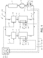
- Fig. 1 is a schematical illustration of a refrigeration system 1 for a vehicle.
- the refrigeration system 1 comprises a circuit 2 containing a refrigerant, a compressor 3, and a first evaporator 4 and a second evaporator 5 which are connected in parallel to the compressor 3.
- the circuit 2 has a main circuit 6, a first subcircuit 7 for the first evaporator 4 and a second subcircuit 8 for the second evaporator 5.
- the compressor 3 is arranged in the main circuit 6 for compressing the refrigerant or working fluid circulating in the circuit 2 of the refrigeration system 1.
- the compressor 3 can be driven by an electric motor (not shown).
- the refrigeration system 1 further comprises a first expansion valve 9 arranged upstream the first evaporator 4 in the first subcircuit 7 and a second expansion valve 10 arranged upstream the second evaporator 5 in the second subcircuit 8.
- the first expansion valve 9 is arranged to regulate a pressure drop of the refrigerant before the first evaporator 4 and the second expansion valve 10 is arranged to regulate a pressure drop of the refrigerant before the second evaporator 5.
- the first and second expansion valves 9, 10 are used for controlling the distribution of the refrigerant flow between the first evaporator 4 and the second evaporator 5. In other words; the flow of the refrigerant in the main circuit 6 is divided into a first flow passing through the first subcircuit 7 and a second flow passing through the second subcircuit 8.
- a condenser 11 is suitably arranged in the main circuit 6 downstream the compressor 3 between the compressor 3 and the first and second expansion valves 9, 10. In operation, heat can be transferred from the surrounding to the refrigerant at the first and second evaporators 4, 5, and heat can be transferred from the refrigerant to the surrounding at the condenser 11.
- the operating principle of the refrigeration system 1 can be as follows.
- the refrigerant being in gaseous state is pressurized and circulated through the system by the compressor 3.
- the flow of refrigerant in the main circuit 6 is controlled by the operation of the compressor 3.
- After passing the compressor 3 the hot and highly pressurized refrigerant is cooled in the condenser 11 until the refrigerant condenses into a highpressure liquid having a lower temperature.
- a first part of the condensed refrigerant passes through the first expansion valve 9, and the remaining part of the condensed refrigerant passes through the second expansion valve 10.
- the low-pressure refrigerant in the first subcircuit 7 then enters the first evaporator 4, where the refrigerant absorbs heat and is evaporated
- the low-pressure refrigerant in the second subcircuit 8 then enters the second evaporator 5, where the refrigerant absorbs heat and is evaporated. Thereafter, the partial flows of refrigerant returns to the main circuit 6 and the compressor 3, and the cycle is repeated.
- the circulating direction of the refrigerant (to which the expressions upstream and downstream refer) in the circuit 2 is indicated by arrows 12.
- the first and second evaporators 4, 5 work as heat exchangers. Heat is transferred to the refrigerant from a first secondary fluid 13 when passing the first evaporator 4, and heat is transferred to the refrigerant from a second secondary fluid 14 when passing the second evaporator 5.
- a liquid coolant such as water can be used as one of the first secondary fluid and the second secondary fluid.
- the first secondary fluid 13 can be water.
- Air or a further liquid coolant can be used as the other of the first secondary fluid and the second secondary fluid.
- the second secondary fluid 14 can be air.
- heat from an electric motor, batteries or any other component and/or from a cabin of the vehicle that needs to be cooled can be transferred to the first evaporator 4 and the second evaporator 5 by means of the first and second secondary fluids 13, 14.
- the condenser 11 can transfer heat to the surrounding air and/or the cabin and/or to any other component of the vehicle that needs to be heated.
- the heat from the condenser 11 can be transferred from the refrigerant to air or to another working fluid.
- Fig. 1 shows a control unit 15 for controlling the refrigeration system 1.
- the control unit 15 is configured to control a total opening of the first expansion valve 9 and the second expansion valve 10, based on a temperature T m and a pressure p m of the refrigerant which refrigerant temperature and refrigerant pressure are measured downstream the first and second evaporators 4, 5 at a position between the first and second evaporators 4, 5 and the compressor 3 in the main circuit 6.
- the refrigerant temperature T m and the refrigerant pressure p m can be measured at any position between a point 16, where the first subcircuit 7 and the second subcircuit 8 merge into the main circuit 6, and the compressor inlet 17, the refrigerant temperature T m and the refrigerant pressure p m are suitably measured close to the compressor inlet 17.
- a temperature sensor 18 and a pressure sensor 19, respectively, can be used for measuring the refrigerant temperature T m and the refrigerant pressure p m .
- Signals 20, 21 from the temperature sensor 18 and the pressure sensor 19 are transmitted to the control unit 15.
- control unit 15 is configured to control the total opening of the first expansion valve 9 and the second expansion valve 10, based on a superheat control error ⁇ SH being a difference between a superheat value SH which is a function of the refrigerant temperature T m and the refrigerant pressure p m , and a superheat target value SH target .
- control signals 22, 23 are transmitted from the control unit 15 for controlling the opening of the first expansion valve 9 and the opening of the second expansion valve 10.
- the total opening of the first expansion valve 9 and the second expansion valve 10 is the sum of the opening degree of the first expansion valve 9 and the opening degree of the second expansion valve 10.
- the degree of opening of the individual expansion valves 9, 10 can be controlled based on the desired cooling power distribution between the first evaporator 4 and the second evaporator 5.
- control unit 15 is configured to control an opening of the first expansion valve 9, based on a temperature T1 of the first secondary fluid 13 measured when the first secondary fluid 13 has passed the first evaporator 4 and a temperature T2 of the second secondary fluid 14 measured when the second secondary fluid has passed the second evaporator 5.
- the first secondary fluid temperature T1 and the second secondary fluid temperature T2 can be measured by temperature sensors 24, 25, preferably at the outlets of the first and second evaporators. Signals 26, 27 from the temperature sensors 24, 25 are transmitted to the control unit 15.
- the control unit 15 is suitably configured to control the opening of the first expansion valve 9, based on a first temperature control error ⁇ T1 being a difference between the temperature T1 of the first secondary fluid and a target temperature T1 target , and a second temperature control error ⁇ T2 being a difference between the temperature T2 of the second secondary fluid and a target temperature T2 target , and preferably the control unit 15 is configured to control the opening of the first expansion valve 9, based on a difference between the first temperature control error ⁇ T1 and the second temperature control error ⁇ T2.
- control unit 15 can be configured to control an opening of the second expansion valve 10 to be the remaining fraction of the total opening of the first expansion valve 9 and the second expansion valve 10 after being reduced by the fraction assigned to be the opening of the first expansion valve 9.
- the control unit 15 may comprise one or more microprocessors and/or one or more memory devices or any other components for executing computer programs or receiving and/or sending control signals for providing the control function. Particularly, the control unit is preferably provided with a computer program comprising program code means for performing all steps of any embodiment of the method described herein.
- the control unit can be a separate component or be integrated in another controller.
- the control unit can be arranged to control other components of the refrigeration system. For example, the control unit is suitably arranged to control the compressor.
- the control unit 15 may comprise one or more controllers of the type P, PI or PID or combinations thereof.
- the control unit 15 can comprise a first PID controller 28 for controlling the total opening of the first expansion valve and the second expansion valve, based on the superheat control error ⁇ SH, and a second PID controller 29 for controlling the opening of the first expansion valve, based on the difference between the first temperature control error ⁇ T1 and the second temperature control error ⁇ T2.
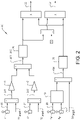
- Fig. 2 shows a control diagram 30 of the control unit 15 for controlling the refrigeration system 1.
- the method comprises controlling the total opening of the first expansion valve and the second expansion valve, based on the temperature T m and the pressure p m of the refrigerant which refrigerant temperature and refrigerant pressure are measured downstream the first and second evaporators at a position between the first and second evaporators and the compressor.
- the method further comprises controlling the total opening of the first expansion valve and the second expansion valve, based on the superheat control error ⁇ SH being the difference between the superheat value SH which is a function of the refrigerant temperature T m and the refrigerant pressure p m , and the superheat target value SH target .
- the first PID controller 28 of the control unit 15 is used for controlling the total opening of the first expansion valve and the second expansion valve.
- the method further comprises controlling the opening of the first expansion valve, based on the temperature T1 of the first secondary fluid measured when the first secondary fluid has passed the first evaporator and the temperature T2 of the second secondary fluid measured when the second secondary fluid has passed the second evaporator.
- the method comprises controlling the opening of the first expansion valve, based on the first temperature control error ⁇ T1 being the difference between the temperature T1 of the first secondary fluid and the target temperature T1 target , and the second temperature control error ⁇ T2 being the difference between the temperature T2 of the second secondary fluid and the target temperature T2 target .
- the method further comprises controlling the opening of the first expansion valve, based on the difference between the first temperature control error ⁇ T1 and the second temperature control error ⁇ T2.
- the second PID controller 29 of the control unit 15 is used for controlling the opening of the first expansion valve.
- the first temperature error ⁇ T1 and the second temperature error ⁇ T2 can be modified by scaling factors K1 and K2 for achieving the system behaviour that is desired.
- the method further comprises controlling the opening of the second expansion valve to be the remaining fraction of the total opening of the first expansion valve and the second expansion valve after being reduced by the fraction assigned to be the opening of the first expansion valve.
Landscapes
- Engineering & Computer Science (AREA)
- Physics & Mathematics (AREA)
- Thermal Sciences (AREA)
- Mechanical Engineering (AREA)
- General Engineering & Computer Science (AREA)
- Air-Conditioning For Vehicles (AREA)
Abstract
Description
- The invention relates to a method and a control unit for controlling a refrigeration system of a vehicle.
- Electric vehicles and plug-in hybrid electric vehicles often have a refrigeration system with two evaporators connected in parallel to a compressor. Such a system is used for a HVAC function and cooling of batteries and motor.
- Depending on various need of cooling and the flows of secondary fluids that are available, different cooling power distributions between the evaporators are desired. At the same time, the requisite superheat level of the refrigerant flowing to the inlet of the compressor has to be ensured.
- An objective of the invention is to provide a method for controlling a refrigeration system of a vehicle, by which method the superheat level of the refrigerant can be ensured at the same time as the desired cooling power distribution between two evaporators of the system can be achieved.
- The objective is achieved by a method for controlling a refrigeration system of a vehicle, where the refrigeration system comprises a circuit containing a refrigerant, a compressor, and a first evaporator and a second evaporator which are connected in parallel to the compressor, and a first expansion valve arranged upstream the first evaporator, which first expansion valve regulates the pressure drop of the refrigerant before the first evaporator, and a second expansion valve arranged upstream the second evaporator, which second expansion valve regulates the pressure drop of the refrigerant before the second evaporator, and a condenser arranged downstream the compressor between the compressor and the first and second expansion valves, where the method comprises controlling a total opening of the first expansion valve and the second expansion valve, based on a temperature and a pressure of the refrigerant, which refrigerant temperature and refrigerant pressure are measured downstream the first and second evaporators at a position between the first and second evaporators and the compressor.
- The invention is based on the insight that by such a method, the issues of ensuring the requisite superheat level of the refrigerant and achieving the desired cooling power distribution between the evaporators can be separated. A target superheat level at the outlet of each evaporator is not required, and there is no need of temperature sensors for measuring the temperature of the refrigerant at each outlet of the evaporators.
- According to one embodiment, the method comprises controlling the total opening of the first expansion valve and the second expansion valve, based on a superheat control error being a difference between a superheat value which is a function of the refrigerant temperature and the refrigerant pressure, and a superheat target value. Hereby, the target superheat can be achieved, further reducing the risk of liquid refrigerant entering the compressor.
- According to a further embodiment, the method comprises controlling an opening of the first expansion valve, based on a temperature of a first secondary fluid measured when the first secondary fluid has passed the first evaporator and a temperature of a second secondary fluid measured when the second secondary fluid has passed the second evaporator. Hereby, the number of sensors used in the system is minimized.
- A liquid coolant such as water can be used as one of the first secondary fluid and the second secondary fluid. Air or a further liquid coolant can be used as the other of the first secondary fluid and the second secondary fluid. For example, heat from the batteries and/or the electric motor, and from the cabin of the vehicle, can be transferred to the first evaporator and the second evaporator, respectively.
- According to a further embodiment, the method comprises controlling the opening of the first expansion valve, based on a first temperature control error being a difference between the temperature of the first secondary fluid and a target temperature, and a second temperature control error being a difference between the temperature of the second secondary fluid and a target temperature, and preferably based on a difference between the first temperature control error and the second temperature control error. Hereby, it is ensured that the fraction assigned to the first evaporator of the refrigeration system's total cooling power can be adapted to the relationship between the need of cooling of the first secondary fluid and that of the second secondary fluid.
- According to a further embodiment, the method comprises controlling an opening of the second expansion valve to be the remaining fraction of the total opening of the first expansion valve and the second expansion valve after being reduced by the fraction assigned to be the opening of the first expansion valve. Hereby, it is ensured that the control unit distributing the refrigeration system's total cooling power between the first and second evaporators is not affecting the total opening area of the first and the second expansion valve.
- The invention also relates to a control unit for controlling a refrigeration system of a vehicle. The advantages of the control unit are similar to the advantages already discussed hereinabove with reference to the different embodiments of the method.
- Further advantages and advantageous features of the invention are disclosed in the following description and in the claims.
- With reference to the appended drawings, below follows a more detailed description of embodiments of the invention cited as examples.
- In the drawings:
-
Fig. 1 shows a refrigeration system for a vehicle, and -
Fig. 2 is a control diagram of a control unit for controlling the refrigeration system. -
Fig. 1 is a schematical illustration of arefrigeration system 1 for a vehicle. Therefrigeration system 1 comprises acircuit 2 containing a refrigerant, a compressor 3, and afirst evaporator 4 and asecond evaporator 5 which are connected in parallel to the compressor 3. Thecircuit 2 has amain circuit 6, afirst subcircuit 7 for thefirst evaporator 4 and asecond subcircuit 8 for thesecond evaporator 5. The compressor 3 is arranged in themain circuit 6 for compressing the refrigerant or working fluid circulating in thecircuit 2 of therefrigeration system 1. The compressor 3 can be driven by an electric motor (not shown). - The
refrigeration system 1 further comprises afirst expansion valve 9 arranged upstream thefirst evaporator 4 in thefirst subcircuit 7 and asecond expansion valve 10 arranged upstream thesecond evaporator 5 in thesecond subcircuit 8. Thefirst expansion valve 9 is arranged to regulate a pressure drop of the refrigerant before thefirst evaporator 4 and thesecond expansion valve 10 is arranged to regulate a pressure drop of the refrigerant before thesecond evaporator 5. In addition to lowering the pressure of the refrigerant, the first andsecond expansion valves first evaporator 4 and thesecond evaporator 5. In other words; the flow of the refrigerant in themain circuit 6 is divided into a first flow passing through thefirst subcircuit 7 and a second flow passing through thesecond subcircuit 8. - Further, a
condenser 11 is suitably arranged in themain circuit 6 downstream the compressor 3 between the compressor 3 and the first andsecond expansion valves second evaporators condenser 11. - The operating principle of the
refrigeration system 1 can be as follows. The refrigerant being in gaseous state is pressurized and circulated through the system by the compressor 3. The flow of refrigerant in themain circuit 6 is controlled by the operation of the compressor 3. After passing the compressor 3 the hot and highly pressurized refrigerant is cooled in thecondenser 11 until the refrigerant condenses into a highpressure liquid having a lower temperature. - A first part of the condensed refrigerant passes through the
first expansion valve 9, and the remaining part of the condensed refrigerant passes through thesecond expansion valve 10. The low-pressure refrigerant in thefirst subcircuit 7 then enters thefirst evaporator 4, where the refrigerant absorbs heat and is evaporated, and the low-pressure refrigerant in thesecond subcircuit 8 then enters thesecond evaporator 5, where the refrigerant absorbs heat and is evaporated. Thereafter, the partial flows of refrigerant returns to themain circuit 6 and the compressor 3, and the cycle is repeated. The circulating direction of the refrigerant (to which the expressions upstream and downstream refer) in thecircuit 2 is indicated byarrows 12. - As schematically illustrated in
Fig. 1 , the first andsecond evaporators secondary fluid 13 when passing thefirst evaporator 4, and heat is transferred to the refrigerant from a secondsecondary fluid 14 when passing thesecond evaporator 5. - When the
refrigeration system 1 is applied on a vehicle, a liquid coolant such as water can be used as one of the first secondary fluid and the second secondary fluid. For example, the firstsecondary fluid 13 can be water. Air or a further liquid coolant can be used as the other of the first secondary fluid and the second secondary fluid. For example, the secondsecondary fluid 14 can be air. - Further, heat from an electric motor, batteries or any other component and/or from a cabin of the vehicle that needs to be cooled, can be transferred to the
first evaporator 4 and thesecond evaporator 5 by means of the first and secondsecondary fluids condenser 11 can transfer heat to the surrounding air and/or the cabin and/or to any other component of the vehicle that needs to be heated. The heat from thecondenser 11 can be transferred from the refrigerant to air or to another working fluid. -
Fig. 1 shows a control unit 15 for controlling therefrigeration system 1. The control unit 15 is configured to control a total opening of thefirst expansion valve 9 and thesecond expansion valve 10, based on a temperature Tm and a pressure pm of the refrigerant which refrigerant temperature and refrigerant pressure are measured downstream the first andsecond evaporators second evaporators main circuit 6. Although the refrigerant temperature Tm and the refrigerant pressure pm can be measured at any position between apoint 16, where thefirst subcircuit 7 and thesecond subcircuit 8 merge into themain circuit 6, and thecompressor inlet 17, the refrigerant temperature Tm and the refrigerant pressure pm are suitably measured close to thecompressor inlet 17. - For measuring the refrigerant temperature Tm and the refrigerant pressure pm, a
temperature sensor 18 and apressure sensor 19, respectively, can be used.Signals temperature sensor 18 and thepressure sensor 19 are transmitted to the control unit 15. - In the example embodiment illustrated, the control unit 15 is configured to control the total opening of the
first expansion valve 9 and thesecond expansion valve 10, based on a superheat control error ΔSH being a difference between a superheat value SH which is a function of the refrigerant temperature Tm and the refrigerant pressure pm, and a superheat target value SHtarget. As illustrated inFig. 1 , control signals 22, 23 are transmitted from the control unit 15 for controlling the opening of thefirst expansion valve 9 and the opening of thesecond expansion valve 10. - The total opening of the
first expansion valve 9 and thesecond expansion valve 10, is the sum of the opening degree of thefirst expansion valve 9 and the opening degree of thesecond expansion valve 10. The degree of opening of theindividual expansion valves first evaporator 4 and thesecond evaporator 5. - In the example embodiment illustrated, the control unit 15 is configured to control an opening of the
first expansion valve 9, based on a temperature T1 of the firstsecondary fluid 13 measured when the firstsecondary fluid 13 has passed thefirst evaporator 4 and a temperature T2 of the secondsecondary fluid 14 measured when the second secondary fluid has passed thesecond evaporator 5. - The first secondary fluid temperature T1 and the second secondary fluid temperature T2 can be measured by
temperature sensors Signals temperature sensors - The control unit 15 is suitably configured to control the opening of the
first expansion valve 9, based on a first temperature control error ΔT1 being a difference between the temperature T1 of the first secondary fluid and a target temperature T1target, and a second temperature control error ΔT2 being a difference between the temperature T2 of the second secondary fluid and a target temperature T2target, and preferably the control unit 15 is configured to control the opening of thefirst expansion valve 9, based on a difference between the first temperature control error ΔT1 and the second temperature control error ΔT2. - Further, the control unit 15 can be configured to control an opening of the
second expansion valve 10 to be the remaining fraction of the total opening of thefirst expansion valve 9 and thesecond expansion valve 10 after being reduced by the fraction assigned to be the opening of thefirst expansion valve 9. - The control unit 15 may comprise one or more microprocessors and/or one or more memory devices or any other components for executing computer programs or receiving and/or sending control signals for providing the control function. Particularly, the control unit is preferably provided with a computer program comprising program code means for performing all steps of any embodiment of the method described herein. The control unit can be a separate component or be integrated in another controller. The control unit can be arranged to control other components of the refrigeration system. For example, the control unit is suitably arranged to control the compressor.
- The control unit 15 may comprise one or more controllers of the type P, PI or PID or combinations thereof. For example, the control unit 15 can comprise a
first PID controller 28 for controlling the total opening of the first expansion valve and the second expansion valve, based on the superheat control error ΔSH, and asecond PID controller 29 for controlling the opening of the first expansion valve, based on the difference between the first temperature control error ΔT1 and the second temperature control error ΔT2. -
Fig. 2 shows a control diagram 30 of the control unit 15 for controlling therefrigeration system 1. Reference is made to the control diagram 30 inFig. 2 (and to therefrigeration system 1 inFig. 1 ), for illustrating an example embodiment of the method. The method comprises controlling the total opening of the first expansion valve and the second expansion valve, based on the temperature Tm and the pressure pm of the refrigerant which refrigerant temperature and refrigerant pressure are measured downstream the first and second evaporators at a position between the first and second evaporators and the compressor. - The method further comprises controlling the total opening of the first expansion valve and the second expansion valve, based on the superheat control error ΔSH being the difference between the superheat value SH which is a function of the refrigerant temperature Tm and the refrigerant pressure pm, and the superheat target value SHtarget. The
first PID controller 28 of the control unit 15 is used for controlling the total opening of the first expansion valve and the second expansion valve. - In the illustrated example embodiment, the method further comprises controlling the opening of the first expansion valve, based on the temperature T1 of the first secondary fluid measured when the first secondary fluid has passed the first evaporator and the temperature T2 of the second secondary fluid measured when the second secondary fluid has passed the second evaporator.
- The method comprises controlling the opening of the first expansion valve, based on the first temperature control error ΔT1 being the difference between the temperature T1 of the first secondary fluid and the target temperature T1target, and the second temperature control error ΔT2 being the difference between the temperature T2 of the second secondary fluid and the target temperature T2target. The method further comprises controlling the opening of the first expansion valve, based on the difference between the first temperature control error ΔT1 and the second temperature control error ΔT2. The
second PID controller 29 of the control unit 15 is used for controlling the opening of the first expansion valve. - The first temperature error ΔT1 and the second temperature error ΔT2 can be modified by scaling factors K1 and K2 for achieving the system behaviour that is desired.
- The method further comprises controlling the opening of the second expansion valve to be the remaining fraction of the total opening of the first expansion valve and the second expansion valve after being reduced by the fraction assigned to be the opening of the first expansion valve.
- It is to be understood that the present invention is not limited to the embodiments described above and illustrated in the drawings; rather, the skilled person will recognize that many changes and modifications may be made within the scope of the appended claims.
Claims (15)
- A method for controlling a refrigeration system (1) of a vehicle, the refrigeration system comprising a circuit (2) containing a refrigerant, a compressor (3), and a first evaporator (4) and a second evaporator (5) which are connected in parallel to the compressor, and a first expansion valve (9) arranged upstream the first evaporator, which first expansion valve regulates a pressure drop of the refrigerant before the first evaporator, and a second expansion valve (10) arranged upstream the second evaporator, which second expansion valve regulates a pressure drop of the refrigerant before the second evaporator, and a condenser (11) arranged downstream the compressor (3) between the compressor and the first and second expansion valves, characterized by controlling a total opening of the first expansion valve (9) and the second expansion valve (10), based on a temperature (Tm) and a pressure (pm) of the refrigerant which refrigerant temperature and refrigerant pressure are measured downstream the first and second evaporators at a position between the first and second evaporators and the compressor.
- A method according to claim 1, characterized by controlling the total opening of the first expansion valve (9) and the second expansion valve (10), based on a superheat control error (ΔSH) being a difference between a superheat value (SH) which is a function of the refrigerant temperature (Tm) and the refrigerant pressure (pm), and a superheat target value (SHtarget).
- A method according to claim 1 or 2, characterized by controlling an opening of the first expansion valve (9), based on a temperature (T1) of a first secondary fluid (13) measured when the first secondary fluid has passed the first evaporator (4) and a temperature (T2) of a second secondary fluid (14) measured when the second secondary fluid has passed the second evaporator (5).
- A method according to claim 3, characterized by controlling the opening of the first expansion valve (9), based on a first temperature control error (ΔT1) being a difference between the temperature (T1) of the first secondary fluid and a target temperature (T1target), and a second temperature control error (ΔT2) being a difference between the temperature (T2) of the second secondary fluid and a target temperature (T2target).
- A method according to claim 4, characterized by controlling the opening of the first expansion valve (9), based on a difference between the first temperature control error (ΔT1) and the second temperature control error (ΔT2).
- A method according to any of claims 3-5, characterized by controlling an opening of the second expansion valve (10) to be the remaining fraction of the total opening of the first expansion valve (9) and the second expansion valve (10) after being reduced by the fraction assigned to be the opening of the first expansion valve (9).
- A method according to any of claims 3-6, characterized by using a liquid coolant as one of the first secondary fluid (13) and the second secondary fluid (14).
- A method according to claim 7, characterized by using air or a further liquid coolant as the other of the first secondary fluid (13) and the second secondary fluid (14).
- A control unit (15) for controlling a refrigeration system (1) of a vehicle, the refrigeration system comprising a circuit (2) containing a refrigerant, a compressor (3), and a first evaporator (4) and a second evaporator (5) which are connected in parallel to the compressor (3), and a first expansion valve (9) arranged upstream the first evaporator, which first expansion valve regulates a pressure drop of the refrigerant before the first evaporator, and a second expansion valve (10) arranged upstream the second evaporator, which second expansion valve regulates a pressure drop of the refrigerant before the second evaporator, and a condenser (11) arranged downstream the compressor (3) between the compressor and the first and second expansion valves, characterized in that the control unit (15) is configured to control a total opening of the first expansion valve (9) and the second expansion valve (10), based on a temperature (Tm) and a pressure (pm) of the refrigerant which refrigerant temperature and refrigerant pressure are measured downstream the first and second evaporators at a position between the first and second evaporators and the compressor.
- A control unit according to claim 9, characterized in that the control unit (15) is configured to control the total opening of the first expansion valve (9) and the second expansion valve (10), based on a superheat control error (ΔSH) being a difference between a superheat value (SH) which is a function of the refrigerant temperature (Tm) and the refrigerant pressure (pm), and a superheat target value (SHtarget).
- A control unit according to claim 9 or 10, characterized in that the control unit (15) is configured to control an opening of the first expansion valve (9), based on a temperature (T1) of a first secondary fluid (13) measured when the first secondary fluid has passed the first evaporator (4) and a temperature (T2) of a second secondary fluid (14) measured when the second secondary fluid has passed the second evaporator (5).
- A control unit according to claim 11, characterized in that the control unit (15) is configured to control the opening of the first expansion valve (9), based on a first temperature control error (ΔT1) being a difference between the temperature (T1) of the first secondary fluid (13) and a target temperature (T1target), and a second temperature control error (ΔT2) being a difference between the temperature (T2) of the second secondary fluid (14) and a target temperature (T2target).
- A control unit according to claim 12, characterized in that the control unit (15) is configured to control the opening of the first expansion valve (9), based on a difference between the first temperature control error (ΔT1) and the second temperature control error (ΔT2).
- A control unit according to any of claims 11-13, characterized in that the control unit (15) is configured to control an opening of the second expansion valve (10) to be the remaining fraction of the total opening of the first expansion valve (9) and the second expansion valve (10) after being reduced by the fraction assigned to be the opening of the first expansion valve (9).
- A computer program comprising program code means for performing a method according to any of claims 1-8.
Priority Applications (4)
| Application Number | Priority Date | Filing Date | Title |
|---|---|---|---|
| EP21169690.1A EP4079549B1 (en) | 2021-04-21 | 2021-04-21 | A method for controlling a refrigeration system of a vehicle |
| PCT/CN2022/086602 WO2022222824A1 (en) | 2021-04-21 | 2022-04-13 | A method for controlling a refrigeration system of a vehicle |
| CN202280027436.2A CN117157204A (en) | 2021-04-21 | 2022-04-13 | Method for controlling a refrigeration system of a vehicle |
| US18/375,603 US12589631B2 (en) | 2021-04-21 | 2023-10-02 | Method for controlling a refrigeration system of a vehicle |
Applications Claiming Priority (1)
| Application Number | Priority Date | Filing Date | Title |
|---|---|---|---|
| EP21169690.1A EP4079549B1 (en) | 2021-04-21 | 2021-04-21 | A method for controlling a refrigeration system of a vehicle |
Publications (2)
| Publication Number | Publication Date |
|---|---|
| EP4079549A1 true EP4079549A1 (en) | 2022-10-26 |
| EP4079549B1 EP4079549B1 (en) | 2024-04-24 |
Family
ID=75639680
Family Applications (1)
| Application Number | Title | Priority Date | Filing Date |
|---|---|---|---|
| EP21169690.1A Active EP4079549B1 (en) | 2021-04-21 | 2021-04-21 | A method for controlling a refrigeration system of a vehicle |
Country Status (4)
| Country | Link |
|---|---|
| US (1) | US12589631B2 (en) |
| EP (1) | EP4079549B1 (en) |
| CN (1) | CN117157204A (en) |
| WO (1) | WO2022222824A1 (en) |
Families Citing this family (1)
| Publication number | Priority date | Publication date | Assignee | Title |
|---|---|---|---|---|
| US20250340100A1 (en) * | 2024-05-06 | 2025-11-06 | Rivian Ip Holdings, Llc | Dynamic heat pump control for electric vehicles |
Citations (3)
| Publication number | Priority date | Publication date | Assignee | Title |
|---|---|---|---|---|
| WO1991003691A1 (en) * | 1989-09-01 | 1991-03-21 | Sundstrand Corporation, Inc. | Vapor cycle system with multiple evaporator load control and superheat control |
| EP2075516A2 (en) * | 2007-12-27 | 2009-07-01 | Mitsubishi Heavy Industries, Ltd. | Refrigeration unit for land transportation and operation control method of refrigeration unit for land transportation |
| DE102017208231A1 (en) * | 2017-05-16 | 2018-11-22 | Audi Ag | Vehicle refrigeration system with a refrigerant circuit |
Family Cites Families (18)
| Publication number | Priority date | Publication date | Assignee | Title |
|---|---|---|---|---|
| DE3743285A1 (en) * | 1987-12-19 | 1989-06-29 | Sueddeutsche Kuehler Behr | DEVICE FOR CONTROLLING THE EXPANSION VALVE OF THE REFRIGERATION DEVICE IN A MOTOR VEHICLE AIR CONDITIONING |
| JPH10157449A (en) * | 1996-11-28 | 1998-06-16 | Denso Corp | Refrigeration cycle device |
| US20060254308A1 (en) * | 2005-05-16 | 2006-11-16 | Denso Corporation | Ejector cycle device |
| JP2007176302A (en) * | 2005-12-27 | 2007-07-12 | Calsonic Kansei Corp | Air-conditioner for vehicle |
| US7874166B2 (en) * | 2006-02-14 | 2011-01-25 | Allen-Vanguard Technologies Inc. | Cooling and climate conditioning system for a vehicle |
| JP4779928B2 (en) * | 2006-10-27 | 2011-09-28 | 株式会社デンソー | Ejector refrigeration cycle |
| KR100927072B1 (en) | 2009-01-29 | 2009-11-13 | 정석권 | Superheat degree and capacity control device of variable speed refrigeration system |
| KR101266435B1 (en) | 2010-08-26 | 2013-05-22 | 한라비스테온공조 주식회사 | Air conditioning system automotive vehicles |
| JP5944154B2 (en) * | 2011-12-09 | 2016-07-05 | サンデンホールディングス株式会社 | Air conditioner for vehicles |
| JP5799924B2 (en) | 2012-09-25 | 2015-10-28 | 株式会社デンソー | Refrigeration cycle equipment |
| US9780422B2 (en) | 2015-05-20 | 2017-10-03 | Ford Global Technologies, Llc | Cabin and battery cooling control for electrified vehicles |
| DE102017214356A1 (en) | 2017-08-17 | 2019-02-21 | Volkswagen Aktiengesellschaft | Air conditioning device for a motor vehicle and method for its operation |
| EP3549799B1 (en) * | 2018-04-04 | 2020-08-19 | Ningbo Geely Automobile Research & Development Co., Ltd. | A vehicle thermal management system |
| CN109094324B (en) * | 2018-07-17 | 2021-09-14 | 蔚来(安徽)控股有限公司 | Automobile, air conditioning system and control method thereof |
| CN111497550B (en) * | 2019-01-31 | 2022-03-18 | 广汽埃安新能源汽车有限公司 | A kind of automobile temperature control device and its control method |
| CN110715466A (en) * | 2019-09-27 | 2020-01-21 | 同济大学 | A multi-connected air conditioning system and its control method |
| CN111146512B (en) * | 2019-12-09 | 2020-09-01 | 清华大学 | Electric vehicle thermal safety management system and method with compound jetting device |
| CN111288676B (en) * | 2020-02-14 | 2021-11-02 | 特灵空调系统(中国)有限公司 | chiller |
-
2021
- 2021-04-21 EP EP21169690.1A patent/EP4079549B1/en active Active
-
2022
- 2022-04-13 CN CN202280027436.2A patent/CN117157204A/en active Pending
- 2022-04-13 WO PCT/CN2022/086602 patent/WO2022222824A1/en not_active Ceased
-
2023
- 2023-10-02 US US18/375,603 patent/US12589631B2/en active Active
Patent Citations (3)
| Publication number | Priority date | Publication date | Assignee | Title |
|---|---|---|---|---|
| WO1991003691A1 (en) * | 1989-09-01 | 1991-03-21 | Sundstrand Corporation, Inc. | Vapor cycle system with multiple evaporator load control and superheat control |
| EP2075516A2 (en) * | 2007-12-27 | 2009-07-01 | Mitsubishi Heavy Industries, Ltd. | Refrigeration unit for land transportation and operation control method of refrigeration unit for land transportation |
| DE102017208231A1 (en) * | 2017-05-16 | 2018-11-22 | Audi Ag | Vehicle refrigeration system with a refrigerant circuit |
Also Published As
| Publication number | Publication date |
|---|---|
| EP4079549B1 (en) | 2024-04-24 |
| US20240034125A1 (en) | 2024-02-01 |
| WO2022222824A1 (en) | 2022-10-27 |
| US12589631B2 (en) | 2026-03-31 |
| CN117157204A (en) | 2023-12-01 |
Similar Documents
| Publication | Publication Date | Title |
|---|---|---|
| EP3699514B1 (en) | Systems and methods for controlling a refrigeration system | |
| CN106196495B (en) | Control device and control method of multi-split air conditioner and multi-split air conditioner | |
| JP7559715B2 (en) | Refrigerant circuit system and control method thereof | |
| US10401068B2 (en) | Air cooled chiller with heat recovery | |
| WO2018039254A1 (en) | Systems and methods for controlling a refrigeration system | |
| CN108076653B (en) | Liquid temperature adjusting device and temperature control system | |
| EP3159630B1 (en) | Air conditioner | |
| CN107747832B (en) | An electric vehicle heat pump air conditioning system and its control method | |
| EP3228951A1 (en) | Refrigeration cycle apparatus | |
| US5150582A (en) | Multiple air conditioning apparatus | |
| KR102893109B1 (en) | Air conditioning apparatus | |
| US12589631B2 (en) | Method for controlling a refrigeration system of a vehicle | |
| CN108116183A (en) | A kind of control method of heat management system | |
| EP3332182B1 (en) | Chiller plant | |
| EP3715735B1 (en) | Air conditioning apparatus | |
| US20230400213A1 (en) | Low charge chiller and free cooling | |
| WO2024250179A1 (en) | Super-high temperature heat pump | |
| CN114074584B (en) | Thermal management system | |
| CN110726196B (en) | Cold liquid integrated system of air conditioner | |
| EP3765800B1 (en) | Condenser architecture with multiple segments | |
| EP2137467A1 (en) | Multi-unit air conditioning system and controlling method for the same | |
| CN101644502B (en) | Refrigerating circuit and method for operating same | |
| WO2024201658A1 (en) | Refrigeration cycle device |
Legal Events
| Date | Code | Title | Description |
|---|---|---|---|
| PUAI | Public reference made under article 153(3) epc to a published international application that has entered the european phase |
Free format text: ORIGINAL CODE: 0009012 |
|
| STAA | Information on the status of an ep patent application or granted ep patent |
Free format text: STATUS: REQUEST FOR EXAMINATION WAS MADE |
|
| 17P | Request for examination filed |
Effective date: 20210421 |
|
| AK | Designated contracting states |
Kind code of ref document: A1 Designated state(s): AL AT BE BG CH CY CZ DE DK EE ES FI FR GB GR HR HU IE IS IT LI LT LU LV MC MK MT NL NO PL PT RO RS SE SI SK SM TR |
|
| GRAP | Despatch of communication of intention to grant a patent |
Free format text: ORIGINAL CODE: EPIDOSNIGR1 |
|
| STAA | Information on the status of an ep patent application or granted ep patent |
Free format text: STATUS: GRANT OF PATENT IS INTENDED |
|
| RIC1 | Information provided on ipc code assigned before grant |
Ipc: F25B 49/02 20060101ALI20231019BHEP Ipc: F25B 5/02 20060101ALI20231019BHEP Ipc: B60H 1/32 20060101AFI20231019BHEP |
|
| INTG | Intention to grant announced |
Effective date: 20231122 |
|
| GRAS | Grant fee paid |
Free format text: ORIGINAL CODE: EPIDOSNIGR3 |
|
| GRAA | (expected) grant |
Free format text: ORIGINAL CODE: 0009210 |
|
| STAA | Information on the status of an ep patent application or granted ep patent |
Free format text: STATUS: THE PATENT HAS BEEN GRANTED |
|
| AK | Designated contracting states |
Kind code of ref document: B1 Designated state(s): AL AT BE BG CH CY CZ DE DK EE ES FI FR GB GR HR HU IE IS IT LI LT LU LV MC MK MT NL NO PL PT RO RS SE SI SK SM TR |
|
| REG | Reference to a national code |
Ref country code: GB Ref legal event code: FG4D |
|
| REG | Reference to a national code |
Ref country code: CH Ref legal event code: EP |
|
| REG | Reference to a national code |
Ref country code: DE Ref legal event code: R096 Ref document number: 602021012124 Country of ref document: DE |
|
| REG | Reference to a national code |
Ref country code: IE Ref legal event code: FG4D |
|
| REG | Reference to a national code |
Ref country code: LT Ref legal event code: MG9D |
|
| REG | Reference to a national code |
Ref country code: NL Ref legal event code: MP Effective date: 20240424 |
|
| REG | Reference to a national code |
Ref country code: AT Ref legal event code: MK05 Ref document number: 1679224 Country of ref document: AT Kind code of ref document: T Effective date: 20240424 |
|
| PG25 | Lapsed in a contracting state [announced via postgrant information from national office to epo] |
Ref country code: NL Free format text: LAPSE BECAUSE OF FAILURE TO SUBMIT A TRANSLATION OF THE DESCRIPTION OR TO PAY THE FEE WITHIN THE PRESCRIBED TIME-LIMIT Effective date: 20240424 |
|
| PG25 | Lapsed in a contracting state [announced via postgrant information from national office to epo] |
Ref country code: NL Free format text: LAPSE BECAUSE OF FAILURE TO SUBMIT A TRANSLATION OF THE DESCRIPTION OR TO PAY THE FEE WITHIN THE PRESCRIBED TIME-LIMIT Effective date: 20240424 |
|
| PG25 | Lapsed in a contracting state [announced via postgrant information from national office to epo] |
Ref country code: IS Free format text: LAPSE BECAUSE OF FAILURE TO SUBMIT A TRANSLATION OF THE DESCRIPTION OR TO PAY THE FEE WITHIN THE PRESCRIBED TIME-LIMIT Effective date: 20240824 |
|
| PG25 | Lapsed in a contracting state [announced via postgrant information from national office to epo] |
Ref country code: BG Free format text: LAPSE BECAUSE OF FAILURE TO SUBMIT A TRANSLATION OF THE DESCRIPTION OR TO PAY THE FEE WITHIN THE PRESCRIBED TIME-LIMIT Effective date: 20240424 |
|
| PG25 | Lapsed in a contracting state [announced via postgrant information from national office to epo] |
Ref country code: HR Free format text: LAPSE BECAUSE OF FAILURE TO SUBMIT A TRANSLATION OF THE DESCRIPTION OR TO PAY THE FEE WITHIN THE PRESCRIBED TIME-LIMIT Effective date: 20240424 Ref country code: FI Free format text: LAPSE BECAUSE OF FAILURE TO SUBMIT A TRANSLATION OF THE DESCRIPTION OR TO PAY THE FEE WITHIN THE PRESCRIBED TIME-LIMIT Effective date: 20240424 |
|
| PG25 | Lapsed in a contracting state [announced via postgrant information from national office to epo] |
Ref country code: GR Free format text: LAPSE BECAUSE OF FAILURE TO SUBMIT A TRANSLATION OF THE DESCRIPTION OR TO PAY THE FEE WITHIN THE PRESCRIBED TIME-LIMIT Effective date: 20240725 |
|
| PG25 | Lapsed in a contracting state [announced via postgrant information from national office to epo] |
Ref country code: PT Free format text: LAPSE BECAUSE OF FAILURE TO SUBMIT A TRANSLATION OF THE DESCRIPTION OR TO PAY THE FEE WITHIN THE PRESCRIBED TIME-LIMIT Effective date: 20240826 |
|
| PG25 | Lapsed in a contracting state [announced via postgrant information from national office to epo] |
Ref country code: ES Free format text: LAPSE BECAUSE OF FAILURE TO SUBMIT A TRANSLATION OF THE DESCRIPTION OR TO PAY THE FEE WITHIN THE PRESCRIBED TIME-LIMIT Effective date: 20240424 |
|
| PG25 | Lapsed in a contracting state [announced via postgrant information from national office to epo] |
Ref country code: AT Free format text: LAPSE BECAUSE OF FAILURE TO SUBMIT A TRANSLATION OF THE DESCRIPTION OR TO PAY THE FEE WITHIN THE PRESCRIBED TIME-LIMIT Effective date: 20240424 |
|
| PG25 | Lapsed in a contracting state [announced via postgrant information from national office to epo] |
Ref country code: PL Free format text: LAPSE BECAUSE OF FAILURE TO SUBMIT A TRANSLATION OF THE DESCRIPTION OR TO PAY THE FEE WITHIN THE PRESCRIBED TIME-LIMIT Effective date: 20240424 |
|
| PG25 | Lapsed in a contracting state [announced via postgrant information from national office to epo] |
Ref country code: LV Free format text: LAPSE BECAUSE OF FAILURE TO SUBMIT A TRANSLATION OF THE DESCRIPTION OR TO PAY THE FEE WITHIN THE PRESCRIBED TIME-LIMIT Effective date: 20240424 |
|
| PG25 | Lapsed in a contracting state [announced via postgrant information from national office to epo] |
Ref country code: PT Free format text: LAPSE BECAUSE OF FAILURE TO SUBMIT A TRANSLATION OF THE DESCRIPTION OR TO PAY THE FEE WITHIN THE PRESCRIBED TIME-LIMIT Effective date: 20240826 Ref country code: PL Free format text: LAPSE BECAUSE OF FAILURE TO SUBMIT A TRANSLATION OF THE DESCRIPTION OR TO PAY THE FEE WITHIN THE PRESCRIBED TIME-LIMIT Effective date: 20240424 Ref country code: NO Free format text: LAPSE BECAUSE OF FAILURE TO SUBMIT A TRANSLATION OF THE DESCRIPTION OR TO PAY THE FEE WITHIN THE PRESCRIBED TIME-LIMIT Effective date: 20240724 Ref country code: LV Free format text: LAPSE BECAUSE OF FAILURE TO SUBMIT A TRANSLATION OF THE DESCRIPTION OR TO PAY THE FEE WITHIN THE PRESCRIBED TIME-LIMIT Effective date: 20240424 Ref country code: IS Free format text: LAPSE BECAUSE OF FAILURE TO SUBMIT A TRANSLATION OF THE DESCRIPTION OR TO PAY THE FEE WITHIN THE PRESCRIBED TIME-LIMIT Effective date: 20240824 Ref country code: HR Free format text: LAPSE BECAUSE OF FAILURE TO SUBMIT A TRANSLATION OF THE DESCRIPTION OR TO PAY THE FEE WITHIN THE PRESCRIBED TIME-LIMIT Effective date: 20240424 Ref country code: GR Free format text: LAPSE BECAUSE OF FAILURE TO SUBMIT A TRANSLATION OF THE DESCRIPTION OR TO PAY THE FEE WITHIN THE PRESCRIBED TIME-LIMIT Effective date: 20240725 Ref country code: FI Free format text: LAPSE BECAUSE OF FAILURE TO SUBMIT A TRANSLATION OF THE DESCRIPTION OR TO PAY THE FEE WITHIN THE PRESCRIBED TIME-LIMIT Effective date: 20240424 Ref country code: ES Free format text: LAPSE BECAUSE OF FAILURE TO SUBMIT A TRANSLATION OF THE DESCRIPTION OR TO PAY THE FEE WITHIN THE PRESCRIBED TIME-LIMIT Effective date: 20240424 Ref country code: BG Free format text: LAPSE BECAUSE OF FAILURE TO SUBMIT A TRANSLATION OF THE DESCRIPTION OR TO PAY THE FEE WITHIN THE PRESCRIBED TIME-LIMIT Effective date: 20240424 Ref country code: AT Free format text: LAPSE BECAUSE OF FAILURE TO SUBMIT A TRANSLATION OF THE DESCRIPTION OR TO PAY THE FEE WITHIN THE PRESCRIBED TIME-LIMIT Effective date: 20240424 Ref country code: RS Free format text: LAPSE BECAUSE OF FAILURE TO SUBMIT A TRANSLATION OF THE DESCRIPTION OR TO PAY THE FEE WITHIN THE PRESCRIBED TIME-LIMIT Effective date: 20240724 |
|
| PG25 | Lapsed in a contracting state [announced via postgrant information from national office to epo] |
Ref country code: DK Free format text: LAPSE BECAUSE OF FAILURE TO SUBMIT A TRANSLATION OF THE DESCRIPTION OR TO PAY THE FEE WITHIN THE PRESCRIBED TIME-LIMIT Effective date: 20240424 |
|
| PG25 | Lapsed in a contracting state [announced via postgrant information from national office to epo] |
Ref country code: EE Free format text: LAPSE BECAUSE OF FAILURE TO SUBMIT A TRANSLATION OF THE DESCRIPTION OR TO PAY THE FEE WITHIN THE PRESCRIBED TIME-LIMIT Effective date: 20240424 |
|
| PG25 | Lapsed in a contracting state [announced via postgrant information from national office to epo] |
Ref country code: CZ Free format text: LAPSE BECAUSE OF FAILURE TO SUBMIT A TRANSLATION OF THE DESCRIPTION OR TO PAY THE FEE WITHIN THE PRESCRIBED TIME-LIMIT Effective date: 20240424 |
|
| PG25 | Lapsed in a contracting state [announced via postgrant information from national office to epo] |
Ref country code: SK Free format text: LAPSE BECAUSE OF FAILURE TO SUBMIT A TRANSLATION OF THE DESCRIPTION OR TO PAY THE FEE WITHIN THE PRESCRIBED TIME-LIMIT Effective date: 20240424 Ref country code: RO Free format text: LAPSE BECAUSE OF FAILURE TO SUBMIT A TRANSLATION OF THE DESCRIPTION OR TO PAY THE FEE WITHIN THE PRESCRIBED TIME-LIMIT Effective date: 20240424 |
|
| REG | Reference to a national code |
Ref country code: DE Ref legal event code: R097 Ref document number: 602021012124 Country of ref document: DE |
|
| PG25 | Lapsed in a contracting state [announced via postgrant information from national office to epo] |
Ref country code: SM Free format text: LAPSE BECAUSE OF FAILURE TO SUBMIT A TRANSLATION OF THE DESCRIPTION OR TO PAY THE FEE WITHIN THE PRESCRIBED TIME-LIMIT Effective date: 20240424 |
|
| PG25 | Lapsed in a contracting state [announced via postgrant information from national office to epo] |
Ref country code: SM Free format text: LAPSE BECAUSE OF FAILURE TO SUBMIT A TRANSLATION OF THE DESCRIPTION OR TO PAY THE FEE WITHIN THE PRESCRIBED TIME-LIMIT Effective date: 20240424 Ref country code: SK Free format text: LAPSE BECAUSE OF FAILURE TO SUBMIT A TRANSLATION OF THE DESCRIPTION OR TO PAY THE FEE WITHIN THE PRESCRIBED TIME-LIMIT Effective date: 20240424 Ref country code: RO Free format text: LAPSE BECAUSE OF FAILURE TO SUBMIT A TRANSLATION OF THE DESCRIPTION OR TO PAY THE FEE WITHIN THE PRESCRIBED TIME-LIMIT Effective date: 20240424 Ref country code: EE Free format text: LAPSE BECAUSE OF FAILURE TO SUBMIT A TRANSLATION OF THE DESCRIPTION OR TO PAY THE FEE WITHIN THE PRESCRIBED TIME-LIMIT Effective date: 20240424 Ref country code: DK Free format text: LAPSE BECAUSE OF FAILURE TO SUBMIT A TRANSLATION OF THE DESCRIPTION OR TO PAY THE FEE WITHIN THE PRESCRIBED TIME-LIMIT Effective date: 20240424 Ref country code: CZ Free format text: LAPSE BECAUSE OF FAILURE TO SUBMIT A TRANSLATION OF THE DESCRIPTION OR TO PAY THE FEE WITHIN THE PRESCRIBED TIME-LIMIT Effective date: 20240424 |
|
| PLBE | No opposition filed within time limit |
Free format text: ORIGINAL CODE: 0009261 |
|
| STAA | Information on the status of an ep patent application or granted ep patent |
Free format text: STATUS: NO OPPOSITION FILED WITHIN TIME LIMIT |
|
| 26N | No opposition filed |
Effective date: 20250127 |
|
| PG25 | Lapsed in a contracting state [announced via postgrant information from national office to epo] |
Ref country code: SI Free format text: LAPSE BECAUSE OF FAILURE TO SUBMIT A TRANSLATION OF THE DESCRIPTION OR TO PAY THE FEE WITHIN THE PRESCRIBED TIME-LIMIT Effective date: 20240424 |
|
| PGFP | Annual fee paid to national office [announced via postgrant information from national office to epo] |
Ref country code: DE Payment date: 20250305 Year of fee payment: 5 |
|
| PG25 | Lapsed in a contracting state [announced via postgrant information from national office to epo] |
Ref country code: SE Free format text: LAPSE BECAUSE OF FAILURE TO SUBMIT A TRANSLATION OF THE DESCRIPTION OR TO PAY THE FEE WITHIN THE PRESCRIBED TIME-LIMIT Effective date: 20240424 |
|
| REG | Reference to a national code |
Ref country code: CH Ref legal event code: H13 Free format text: ST27 STATUS EVENT CODE: U-0-0-H10-H13 (AS PROVIDED BY THE NATIONAL OFFICE) Effective date: 20251125 |
|
| PG25 | Lapsed in a contracting state [announced via postgrant information from national office to epo] |
Ref country code: LU Free format text: LAPSE BECAUSE OF NON-PAYMENT OF DUE FEES Effective date: 20250421 |
|
| PG25 | Lapsed in a contracting state [announced via postgrant information from national office to epo] |
Ref country code: MC Free format text: LAPSE BECAUSE OF FAILURE TO SUBMIT A TRANSLATION OF THE DESCRIPTION OR TO PAY THE FEE WITHIN THE PRESCRIBED TIME-LIMIT Effective date: 20240424 |
|
| REG | Reference to a national code |
Ref country code: BE Ref legal event code: MM Effective date: 20250430 |
|
| PG25 | Lapsed in a contracting state [announced via postgrant information from national office to epo] |
Ref country code: BE Free format text: LAPSE BECAUSE OF NON-PAYMENT OF DUE FEES Effective date: 20250430 |
|
| PG25 | Lapsed in a contracting state [announced via postgrant information from national office to epo] |
Ref country code: CH Free format text: LAPSE BECAUSE OF NON-PAYMENT OF DUE FEES Effective date: 20250430 |
|
| PG25 | Lapsed in a contracting state [announced via postgrant information from national office to epo] |
Ref country code: IT Free format text: LAPSE BECAUSE OF FAILURE TO SUBMIT A TRANSLATION OF THE DESCRIPTION OR TO PAY THE FEE WITHIN THE PRESCRIBED TIME-LIMIT Effective date: 20240424 |
|
| PGFP | Annual fee paid to national office [announced via postgrant information from national office to epo] |
Ref country code: GB Payment date: 20260203 Year of fee payment: 6 |
|
| PG25 | Lapsed in a contracting state [announced via postgrant information from national office to epo] |
Ref country code: IE Free format text: LAPSE BECAUSE OF NON-PAYMENT OF DUE FEES Effective date: 20250421 |
|
| PGFP | Annual fee paid to national office [announced via postgrant information from national office to epo] |
Ref country code: FR Payment date: 20260202 Year of fee payment: 6 |