EP4079338A1 - Ion generator, fan coil unit and air conditioning system - Google Patents
Ion generator, fan coil unit and air conditioning system Download PDFInfo
- Publication number
- EP4079338A1 EP4079338A1 EP22168874.0A EP22168874A EP4079338A1 EP 4079338 A1 EP4079338 A1 EP 4079338A1 EP 22168874 A EP22168874 A EP 22168874A EP 4079338 A1 EP4079338 A1 EP 4079338A1
- Authority
- EP
- European Patent Office
- Prior art keywords
- plate
- ion generator
- negative plate
- negative
- positive
- Prior art date
- Legal status (The legal status is an assumption and is not a legal conclusion. Google has not performed a legal analysis and makes no representation as to the accuracy of the status listed.)
- Granted
Links
Images
Classifications
-
- A—HUMAN NECESSITIES
- A61—MEDICAL OR VETERINARY SCIENCE; HYGIENE
- A61L—METHODS OR APPARATUS FOR STERILISING MATERIALS OR OBJECTS IN GENERAL; DISINFECTION, STERILISATION OR DEODORISATION OF AIR; CHEMICAL ASPECTS OF BANDAGES, DRESSINGS, ABSORBENT PADS OR SURGICAL ARTICLES; MATERIALS FOR BANDAGES, DRESSINGS, ABSORBENT PADS OR SURGICAL ARTICLES
- A61L9/00—Disinfection, sterilisation or deodorisation of air
- A61L9/16—Disinfection, sterilisation or deodorisation of air using physical phenomena
- A61L9/22—Ionisation
-
- F—MECHANICAL ENGINEERING; LIGHTING; HEATING; WEAPONS; BLASTING
- F24—HEATING; RANGES; VENTILATING
- F24F—AIR-CONDITIONING; AIR-HUMIDIFICATION; VENTILATION; USE OF AIR CURRENTS FOR SCREENING
- F24F8/00—Treatment, e.g. purification, of air supplied to human living or working spaces otherwise than by heating, cooling, humidifying or drying
- F24F8/30—Treatment, e.g. purification, of air supplied to human living or working spaces otherwise than by heating, cooling, humidifying or drying by ionisation
-
- H—ELECTRICITY
- H01—ELECTRIC ELEMENTS
- H01T—SPARK GAPS; OVERVOLTAGE ARRESTERS USING SPARK GAPS; SPARKING PLUGS; CORONA DEVICES; GENERATING IONS TO BE INTRODUCED INTO NON-ENCLOSED GASES
- H01T23/00—Apparatus for generating ions to be introduced into non-enclosed gases, e.g. into the atmosphere
-
- F—MECHANICAL ENGINEERING; LIGHTING; HEATING; WEAPONS; BLASTING
- F24—HEATING; RANGES; VENTILATING
- F24F—AIR-CONDITIONING; AIR-HUMIDIFICATION; VENTILATION; USE OF AIR CURRENTS FOR SCREENING
- F24F1/00—Room units for air-conditioning, e.g. separate or self-contained units or units receiving primary air from a central station
- F24F1/0007—Indoor units, e.g. fan coil units
- F24F1/0071—Indoor units, e.g. fan coil units with means for purifying supplied air
- F24F1/0076—Indoor units, e.g. fan coil units with means for purifying supplied air by electric means, e.g. ionisers or electrostatic separators
-
- F—MECHANICAL ENGINEERING; LIGHTING; HEATING; WEAPONS; BLASTING
- F24—HEATING; RANGES; VENTILATING
- F24F—AIR-CONDITIONING; AIR-HUMIDIFICATION; VENTILATION; USE OF AIR CURRENTS FOR SCREENING
- F24F11/00—Control or safety arrangements
- F24F11/88—Electrical aspects, e.g. circuits
-
- H—ELECTRICITY
- H01—ELECTRIC ELEMENTS
- H01J—ELECTRIC DISCHARGE TUBES OR DISCHARGE LAMPS
- H01J37/00—Discharge tubes with provision for introducing objects or material to be exposed to the discharge, e.g. for the purpose of examination or processing thereof
- H01J37/02—Details
- H01J37/04—Arrangements of electrodes and associated parts for generating or controlling the discharge, e.g. electron-optical arrangement or ion-optical arrangement
- H01J37/08—Ion sources; Ion guns
-
- H—ELECTRICITY
- H01—ELECTRIC ELEMENTS
- H01T—SPARK GAPS; OVERVOLTAGE ARRESTERS USING SPARK GAPS; SPARKING PLUGS; CORONA DEVICES; GENERATING IONS TO BE INTRODUCED INTO NON-ENCLOSED GASES
- H01T19/00—Devices providing for corona discharge
-
- A—HUMAN NECESSITIES
- A61—MEDICAL OR VETERINARY SCIENCE; HYGIENE
- A61L—METHODS OR APPARATUS FOR STERILISING MATERIALS OR OBJECTS IN GENERAL; DISINFECTION, STERILISATION OR DEODORISATION OF AIR; CHEMICAL ASPECTS OF BANDAGES, DRESSINGS, ABSORBENT PADS OR SURGICAL ARTICLES; MATERIALS FOR BANDAGES, DRESSINGS, ABSORBENT PADS OR SURGICAL ARTICLES
- A61L2209/00—Aspects relating to disinfection, sterilisation or deodorisation of air
- A61L2209/10—Apparatus features
- A61L2209/16—Connections to a HVAC unit
-
- B—PERFORMING OPERATIONS; TRANSPORTING
- B03—SEPARATION OF SOLID MATERIALS USING LIQUIDS OR USING PNEUMATIC TABLES OR JIGS; MAGNETIC OR ELECTROSTATIC SEPARATION OF SOLID MATERIALS FROM SOLID MATERIALS OR FLUIDS; SEPARATION BY HIGH-VOLTAGE ELECTRIC FIELDS
- B03C—MAGNETIC OR ELECTROSTATIC SEPARATION OF SOLID MATERIALS FROM SOLID MATERIALS OR FLUIDS; SEPARATION BY HIGH-VOLTAGE ELECTRIC FIELDS
- B03C2201/00—Details of magnetic or electrostatic separation
- B03C2201/10—Ionising electrode with two or more serrated ends or sides
-
- B—PERFORMING OPERATIONS; TRANSPORTING
- B03—SEPARATION OF SOLID MATERIALS USING LIQUIDS OR USING PNEUMATIC TABLES OR JIGS; MAGNETIC OR ELECTROSTATIC SEPARATION OF SOLID MATERIALS FROM SOLID MATERIALS OR FLUIDS; SEPARATION BY HIGH-VOLTAGE ELECTRIC FIELDS
- B03C—MAGNETIC OR ELECTROSTATIC SEPARATION OF SOLID MATERIALS FROM SOLID MATERIALS OR FLUIDS; SEPARATION BY HIGH-VOLTAGE ELECTRIC FIELDS
- B03C3/00—Separating dispersed particles from gases or vapour, e.g. air, by electrostatic effect
- B03C3/34—Constructional details or accessories or operation thereof
- B03C3/38—Particle charging or ionising stations, e.g. using electric discharge, radioactive radiation or flames
-
- B—PERFORMING OPERATIONS; TRANSPORTING
- B03—SEPARATION OF SOLID MATERIALS USING LIQUIDS OR USING PNEUMATIC TABLES OR JIGS; MAGNETIC OR ELECTROSTATIC SEPARATION OF SOLID MATERIALS FROM SOLID MATERIALS OR FLUIDS; SEPARATION BY HIGH-VOLTAGE ELECTRIC FIELDS
- B03C—MAGNETIC OR ELECTROSTATIC SEPARATION OF SOLID MATERIALS FROM SOLID MATERIALS OR FLUIDS; SEPARATION BY HIGH-VOLTAGE ELECTRIC FIELDS
- B03C3/00—Separating dispersed particles from gases or vapour, e.g. air, by electrostatic effect
- B03C3/34—Constructional details or accessories or operation thereof
- B03C3/40—Electrode constructions
- B03C3/41—Ionising-electrodes
-
- B—PERFORMING OPERATIONS; TRANSPORTING
- B03—SEPARATION OF SOLID MATERIALS USING LIQUIDS OR USING PNEUMATIC TABLES OR JIGS; MAGNETIC OR ELECTROSTATIC SEPARATION OF SOLID MATERIALS FROM SOLID MATERIALS OR FLUIDS; SEPARATION BY HIGH-VOLTAGE ELECTRIC FIELDS
- B03C—MAGNETIC OR ELECTROSTATIC SEPARATION OF SOLID MATERIALS FROM SOLID MATERIALS OR FLUIDS; SEPARATION BY HIGH-VOLTAGE ELECTRIC FIELDS
- B03C3/00—Separating dispersed particles from gases or vapour, e.g. air, by electrostatic effect
- B03C3/34—Constructional details or accessories or operation thereof
- B03C3/40—Electrode constructions
- B03C3/60—Use of special materials other than liquids
-
- H—ELECTRICITY
- H01—ELECTRIC ELEMENTS
- H01J—ELECTRIC DISCHARGE TUBES OR DISCHARGE LAMPS
- H01J2237/00—Discharge tubes exposing object to beam, e.g. for analysis treatment, etching, imaging
- H01J2237/20—Positioning, supporting, modifying or maintaining the physical state of objects being observed or treated
- H01J2237/208—Elements or methods for movement independent of sample stage for influencing or moving or contacting or transferring the sample or parts thereof, e.g. prober needles or transfer needles in FIB/SEM systems
-
- Y—GENERAL TAGGING OF NEW TECHNOLOGICAL DEVELOPMENTS; GENERAL TAGGING OF CROSS-SECTIONAL TECHNOLOGIES SPANNING OVER SEVERAL SECTIONS OF THE IPC; TECHNICAL SUBJECTS COVERED BY FORMER USPC CROSS-REFERENCE ART COLLECTIONS [XRACs] AND DIGESTS
- Y02—TECHNOLOGIES OR APPLICATIONS FOR MITIGATION OR ADAPTATION AGAINST CLIMATE CHANGE
- Y02A—TECHNOLOGIES FOR ADAPTATION TO CLIMATE CHANGE
- Y02A50/00—TECHNOLOGIES FOR ADAPTATION TO CLIMATE CHANGE in human health protection, e.g. against extreme weather
- Y02A50/20—Air quality improvement or preservation, e.g. vehicle emission control or emission reduction by using catalytic converters
Definitions
- the present invention relates to the field of air circulation systems, in particular to an ion generator for an air conditioning system and an air conditioning system.
- Negative ions have negative charges, which can absorb dusts and other substances in the air, making them gather and fall, thereby purifying the air.
- Plasmas can function to sterilize the air and removing odors in the air.
- common air purification devices generally provide one of plasmas and negative ions.
- the objective of the present invention is to solve or at least alleviate the problems existing in the prior art.
- an ion generator for an air circulation system which comprises:
- the ground plate, the negative plate and the positive plate are arranged in parallel to each other.
- the two ends of the ground plate, the negative plate and the positive plate are respectively connected to a first mounting bracket and a second mounting bracket, and the power module is arranged in the first mounting bracket or the second mounting bracket.
- the carbon fiber brushes of the negative plate and the positive plate are gathered into bundles by carbon fiber brush protective covers.
- the ground plate is made of a metal material, with openings provided thereon at corresponding positions to the plurality of plasma needles.
- the positions of the plurality of plasma needles on the first side of the negative plate correspond to the positions of the plurality of carbon fiber brushes on the second side of the negative plate.
- the plurality of plasma needles on the first side of the negative plate are evenly arranged at equal intervals and/or the plurality of carbon fiber brushes on the second side of the negative plate are evenly arranged at equal intervals.
- the power module is configured to apply a voltage to the negative plate which is greater than the voltage applied to the positive plate, and optionally, the power module applies a voltage to the negative plate which is 1.5 to 2.5 times the voltage applied to the positive plate.
- a fan coil unit provided with the ion generator according to the first aspect of the present invention wherein, in the fan coil unit, the fan coil unit comprises a middle plate, a motor mounted on the middle plate, volute(s) located on at least one side of the motor, and fan(s) located in the at least one volute(s) driven by the motor, wherein, holes are provided on the middle plate, the ion generator is mounted on the upper side of the motor mounting position on the middle plate, and the generated ions are added into the return air flow passing through the holes.
- an air conditioning system which comprises the fan coil unit according to the second aspect of the present invention.
- the ion generator according to the embodiments of the present invention can simultaneously generate plasmas, negative ions and positive and negative ions, has a simple structure, and is highly integrated.
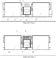
- FIG. 1 is a rear view of a fan coil unit according to an embodiment, i.e., a view from the inner side of a middle plate 3 of a fan coil unit.
- the fan coil unit according to the embodiment may comprise a motor 1 provided in the middle, the motor 1 being mounted, for example, on the middle plate 3.
- Output shafts 11, 12 of the motor 1 can be respectively connected to fans (not shown) located in fan volutes 21, 22 on both sides of the motor, thereby driving the fans in the volutes 21, 22 to rotate, so as to send the air out of the plane defined by the middle plate 3 and sends it into the room.
- the volutes 21, 22 may be, for example, centrifugal fan volutes, cross-flow fan volutes, or volutes of other types of fans.
- the fan coil unit according to the embodiment of the present invention is further provided with a plurality of holes 31 on the middle plate 3, such as in a position above the motor 1 or other suitable positions. Since the air in the area on the inner side of the middle plate 3 corresponding to the plurality of holes 31 may be partially drawn away by the fans, this area will form a negative pressure and thus draw some air from the room on the outer side of the middle plate 3. As shown in FIG.
- the ion generator 4 may be mounted to be aligned with the plurality of holes 31, whereby the ion generator 4 may add plasmas, positive and negative ions, and negative ions into the return air through the plurality of holes 31.
- a part of the return air may be drawn by the fans and thus participates in the indoor air circulation, and the other part of return air returns to the room through other passages, such as returning to the room through the plurality of holes 31.
- plasmas, negative ions, and positive and negative ions may function to purify the air, deodorize, and/or sterilize.
- the ion generator according to the respective embodiments is described herein in connection with an air circulation system, particularly a fan coil of an air conditioning system, in alternative embodiments, however, the ion generator according to the embodiment may be applied to other air circulation systems, such as fresh air systems, air purifiers, and the like.
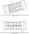
- FIGS. 3 and 4 An ion generator according to an embodiment of the present invention will be introduced with continued reference to FIGS. 3 and 4 , which comprises: a power module 100; a negative plate 5 connected to the power module 100, wherein the negative plate 5 has a first side 51 and a second side 52; a ground plate 6 spaced apart from the first side 51 of the negative plate 5, wherein the first side 51 of the negative plate 5 comprises a plurality of plasma needles 53 extending toward the ground plate 6 but being not in contact with (spaced apart from) the ground plate 6; a positive plate 7 spaced apart from the second side 52 of the negative plate 5, wherein the positive plate 7 is connected to the power module 100 and has a polarity opposite to that of the negative plate 5, and the respective sides of the negative plate 5 and the positive plate 7 that are facing toward each other are respectively provided with a plurality of carbon fiber brushes 54, 74 at corresponding positions.
- the plurality of carbon fiber brushes 54 on the negative plate 5 may carry a negative high voltage supplied by the power module 100
- the plurality of carbon fiber brushes 74 on the positive plate 7 may carry a positive high voltage supplied by the power module 100.
- the negative plate 5 and the positive plate 7 may be printed circuit boards on which copper wires are provided to conduct the power voltage to the positions of the carbon fiber brushes and the plasma needles.
- the power module 100 may be connected to a conventional power source, such as a 220v power source, which is then converted into a high voltage that is applied to the positive plate 7 and the negative plate 5.
- the negative plate 5 may have a voltage greater than that of the positive plate 7, e.g., the voltage of the negative plate 5 is 1.5 to 2.5 times the voltage of the positive plate 7.
- the positive plate 7 may have a voltage of positive 5 kV
- the negative plate 5 may have a voltage of negative 10 kV, that is, the voltage of the negative plate 5 is twice the voltage of the positive plate 7.
- both negative ions and positive and negative ions are generated between the positive plate 7 and the negative plate 5.
- the ion generator according to the embodiment of the present invention can simultaneously generate positive and negative ions, negative ions and plasmas.
- the plasma generator and the positive and negative ion generator according to the embodiment of the present invention share the same negative plate 5, which improves the integration of the device and makes the device exceptionally compact, so that it can be mounted in a narrow space on the back side of the middle plate 3.
- the ground plate 6, the negative plate 5 and the positive plate 7 may be arranged parallel to each other.
- the distance between the negative plate 5 and the ground plate 6 is equivalent to the distance between the negative plate 5 and the positive plate 7.
- both the distances are 40 mm or, as another example, the distance between the negative plate 5 and the ground plate 6 and the distance between the negative plate 5 and the positive plate 7 are both within the range of 30mm-50mm.
- the ion generator 4 further comprises a first mounting bracket 8 and a second mounting bracket 9 connected to the two ends of the ground plate 6, the negative plate 5 and the positive plate 7, and the power module 100 can be arranged in the first mounting bracket 8 or the second mounting bracket 9.
- the power module 100 is arranged in the second mounting bracket 9 and is enclosed by the housing of the second mounting bracket 9.
- the first mounting bracket 8 and the second mounting bracket 9 are provided with mounting holes 81, 91, so as to fix them to the middle plate 3 by means of bolts.
- the carbon fiber brushes 54, 74 of the negative plate 5 and the positive plate 7 are gathered into bundles by carbon fiber brush protective covers 55, 75, which can be attached to the negative plate 5 and the positive plate 7.
- the carbon fiber brushes 54, 74 on the negative plate 5 and the positive plate 7 are spaced apart by an appropriate distance, thereby generating negative ions and positive and negative ions therebetween.
- the ground plate 6 may be provided with openings 61 corresponding to the positions of the plurality of plasma needles 53, thereby generating plasmas.
- the ground plate 6 may, for example, be made of stainless steel, such as S50C.
- the positions of the plurality of plasma needles 53 on the first side 51 of the negative plate 5 correspond to the positions of the plurality of carbon fiber brushes 54 on the second side 52 of the negative plate 5. Since the negative plate 5 is a printed circuit board, arranging the plasma needles 53 and the carbon fiber brushes 54 on the two sides of the negative plate 5 in corresponding positions can simplify the design and manufacture of the printed circuit board. In some embodiments, the plurality of plasma needles 53 on the first side 51 of the negative plate 5 and/or the plurality of carbon fiber brushes 54 on the second side 52 of the negative plate 5 are evenly arranged at equal intervals, so that plasmas, negative ions and positive and negative ions can be more evenly generated.
- the present invention also aims to protect a fan coil unit comprising the ion generator according to the respective embodiments.
- the fan coil unit comprises a middle plate 3 with a plurality of holes 31 provided thereon, a motor 1 arranged on the back side of the middle plate 3, volutes 21, 22 arranged on at least one side or both sides of the motor 1, and fan(s) located in at least one volute(s) driven by the motor 1 through the motor shafts 11, 12.
- the ion generator 4 is arranged on the back side of the middle plate 3 and is in alignment with the plurality of holes 31, thereby adding the generated ions into the return air flow through the holes.
- the present invention further aims to protect an air conditioning system comprising the fan coil unit according to the respective embodiments.
Landscapes
- Engineering & Computer Science (AREA)
- Chemical & Material Sciences (AREA)
- General Engineering & Computer Science (AREA)
- Combustion & Propulsion (AREA)
- Mechanical Engineering (AREA)
- Health & Medical Sciences (AREA)
- Analytical Chemistry (AREA)
- Physics & Mathematics (AREA)
- Plasma & Fusion (AREA)
- Epidemiology (AREA)
- Life Sciences & Earth Sciences (AREA)
- Animal Behavior & Ethology (AREA)
- General Health & Medical Sciences (AREA)
- Public Health (AREA)
- Veterinary Medicine (AREA)
- Disinfection, Sterilisation Or Deodorisation Of Air (AREA)
Abstract
Description
- The present invention relates to the field of air circulation systems, in particular to an ion generator for an air conditioning system and an air conditioning system.
- Negative ions have negative charges, which can absorb dusts and other substances in the air, making them gather and fall, thereby purifying the air. Plasmas can function to sterilize the air and removing odors in the air. At present, common air purification devices generally provide one of plasmas and negative ions.
- The objective of the present invention is to solve or at least alleviate the problems existing in the prior art.
- According to a first aspect of the present invention, an ion generator for an air circulation system is provided, which comprises:
- a power module;
- a negative plate connected to the power module;
- a ground plate spaced apart from a first side of the negative plate, wherein the first side of the negative plate comprises a plurality of plasma needles extending toward the ground plate; and
- a positive plate spaced apart from a second side of the negative plate, wherein the positive plate is connected to the power module and has a polarity opposite to that of the negative plate, and the respective sides of the negative plate and the positive plate that are facing toward each other are respectively provided with a plurality of carbon fiber brushes at corresponding positions.
- Optionally, in the ion generator, the ground plate, the negative plate and the positive plate are arranged in parallel to each other.
- Optionally, in the ion generator, the two ends of the ground plate, the negative plate and the positive plate are respectively connected to a first mounting bracket and a second mounting bracket, and the power module is arranged in the first mounting bracket or the second mounting bracket.
- Optionally, in the ion generator, the carbon fiber brushes of the negative plate and the positive plate are gathered into bundles by carbon fiber brush protective covers.
- Optionally, in the ion generator, the ground plate is made of a metal material, with openings provided thereon at corresponding positions to the plurality of plasma needles.
- Optionally, in the ion generator, the positions of the plurality of plasma needles on the first side of the negative plate correspond to the positions of the plurality of carbon fiber brushes on the second side of the negative plate.
- Optionally, in the ion generator, the plurality of plasma needles on the first side of the negative plate are evenly arranged at equal intervals and/or the plurality of carbon fiber brushes on the second side of the negative plate are evenly arranged at equal intervals.
- Optionally, in the ion generator, the power module is configured to apply a voltage to the negative plate which is greater than the voltage applied to the positive plate, and optionally, the power module applies a voltage to the negative plate which is 1.5 to 2.5 times the voltage applied to the positive plate.
- According to a second aspect of the present invention, a fan coil unit provided with the ion generator according to the first aspect of the present invention is provided, wherein, in the fan coil unit, the fan coil unit comprises a middle plate, a motor mounted on the middle plate, volute(s) located on at least one side of the motor, and fan(s) located in the at least one volute(s) driven by the motor, wherein, holes are provided on the middle plate, the ion generator is mounted on the upper side of the motor mounting position on the middle plate, and the generated ions are added into the return air flow passing through the holes.
- According to a third aspect of the present invention, an air conditioning system is provided, which comprises the fan coil unit according to the second aspect of the present invention.
- The ion generator according to the embodiments of the present invention can simultaneously generate plasmas, negative ions and positive and negative ions, has a simple structure, and is highly integrated.
- With reference to the accompanying drawings, the disclosure of the present invention will become easier to understand. Those skilled in the art would easily understand that these drawings are for the purpose of illustration, and are not intended to limit the protection scope of the present invention. In addition, in the figures, similar numerals are used to denote similar components, wherein:
-
FIG. 1 is a rear view of a fan coil unit according to an embodiment of the present invention; -
FIG. 2 is a rear view of a fan coil unit comprising an ion generator according to an embodiment of the present invention; -
FIG. 3 is a perspective view of an ion generator according to an embodiment of the present invention; and -
FIG. 4 is a side view of an ion generator according to an embodiment of the present invention. -
FIG. 1 is a rear view of a fan coil unit according to an embodiment, i.e., a view from the inner side of amiddle plate 3 of a fan coil unit. The fan coil unit according to the embodiment may comprise amotor 1 provided in the middle, themotor 1 being mounted, for example, on themiddle plate 3.Output shafts motor 1 can be respectively connected to fans (not shown) located infan volutes volutes middle plate 3 and sends it into the room. Thevolutes volutes motor 1, in other embodiments, however, it should be understood that there may only be a volute and a fan on one side of themotor 1. In addition to the conventional return air grille, the fan coil unit according to the embodiment of the present invention is further provided with a plurality ofholes 31 on themiddle plate 3, such as in a position above themotor 1 or other suitable positions. Since the air in the area on the inner side of themiddle plate 3 corresponding to the plurality ofholes 31 may be partially drawn away by the fans, this area will form a negative pressure and thus draw some air from the room on the outer side of themiddle plate 3. As shown inFIG. 2 , the ion generator 4 according to the embodiment of the present invention may be mounted to be aligned with the plurality ofholes 31, whereby the ion generator 4 may add plasmas, positive and negative ions, and negative ions into the return air through the plurality ofholes 31. A part of the return air may be drawn by the fans and thus participates in the indoor air circulation, and the other part of return air returns to the room through other passages, such as returning to the room through the plurality ofholes 31. As mentioned, plasmas, negative ions, and positive and negative ions may function to purify the air, deodorize, and/or sterilize. It should be understood that although the ion generator according to the respective embodiments is described herein in connection with an air circulation system, particularly a fan coil of an air conditioning system, in alternative embodiments, however, the ion generator according to the embodiment may be applied to other air circulation systems, such as fresh air systems, air purifiers, and the like. - An ion generator according to an embodiment of the present invention will be introduced with continued reference to
FIGS. 3 and 4 , which comprises: apower module 100; a negative plate 5 connected to thepower module 100, wherein the negative plate 5 has afirst side 51 and asecond side 52; aground plate 6 spaced apart from thefirst side 51 of the negative plate 5, wherein thefirst side 51 of the negative plate 5 comprises a plurality ofplasma needles 53 extending toward theground plate 6 but being not in contact with (spaced apart from) theground plate 6; apositive plate 7 spaced apart from thesecond side 52 of the negative plate 5, wherein thepositive plate 7 is connected to thepower module 100 and has a polarity opposite to that of the negative plate 5, and the respective sides of the negative plate 5 and thepositive plate 7 that are facing toward each other are respectively provided with a plurality ofcarbon fiber brushes carbon fiber brushes 54 on the negative plate 5 may carry a negative high voltage supplied by thepower module 100, and the plurality ofcarbon fiber brushes 74 on thepositive plate 7 may carry a positive high voltage supplied by thepower module 100. The negative plate 5 and thepositive plate 7 may be printed circuit boards on which copper wires are provided to conduct the power voltage to the positions of the carbon fiber brushes and the plasma needles. Thepower module 100 may be connected to a conventional power source, such as a 220v power source, which is then converted into a high voltage that is applied to thepositive plate 7 and the negative plate 5. In order to generate both negative ions and positive and negative ions, the negative plate 5 may have a voltage greater than that of thepositive plate 7, e.g., the voltage of the negative plate 5 is 1.5 to 2.5 times the voltage of thepositive plate 7. In some embodiments, thepositive plate 7 may have a voltage of positive 5 kV, and the negative plate 5 may have a voltage of negative 10 kV, that is, the voltage of the negative plate 5 is twice the voltage of thepositive plate 7. At this time, both negative ions and positive and negative ions are generated between thepositive plate 7 and the negative plate 5. The ion generator according to the embodiment of the present invention can simultaneously generate positive and negative ions, negative ions and plasmas. In addition, in the ion generator, the plasma generator and the positive and negative ion generator according to the embodiment of the present invention share the same negative plate 5, which improves the integration of the device and makes the device exceptionally compact, so that it can be mounted in a narrow space on the back side of themiddle plate 3. - In some embodiments, as is more clearly shown in
FIG. 4 , theground plate 6, the negative plate 5 and thepositive plate 7 may be arranged parallel to each other. In some embodiments, the distance between the negative plate 5 and theground plate 6 is equivalent to the distance between the negative plate 5 and thepositive plate 7. For example, both the distances are 40 mm or, as another example, the distance between the negative plate 5 and theground plate 6 and the distance between the negative plate 5 and thepositive plate 7 are both within the range of 30mm-50mm. In some embodiments, the ion generator 4 further comprises afirst mounting bracket 8 and asecond mounting bracket 9 connected to the two ends of theground plate 6, the negative plate 5 and thepositive plate 7, and thepower module 100 can be arranged in thefirst mounting bracket 8 or thesecond mounting bracket 9. For example, as shown inFIG. 4 , in the embodiment, thepower module 100 is arranged in thesecond mounting bracket 9 and is enclosed by the housing of thesecond mounting bracket 9. In some embodiments, thefirst mounting bracket 8 and thesecond mounting bracket 9 are provided withmounting holes 81, 91, so as to fix them to themiddle plate 3 by means of bolts. - In some embodiments, the
carbon fiber brushes positive plate 7 are gathered into bundles by carbon fiber brushprotective covers positive plate 7. As shown in the figures, thecarbon fiber brushes positive plate 7 are spaced apart by an appropriate distance, thereby generating negative ions and positive and negative ions therebetween. As is more clearly shown inFIG. 3 , theground plate 6 may be provided withopenings 61 corresponding to the positions of the plurality ofplasma needles 53, thereby generating plasmas. Theground plate 6 may, for example, be made of stainless steel, such as S50C. - In some embodiments, the positions of the plurality of
plasma needles 53 on thefirst side 51 of the negative plate 5 correspond to the positions of the plurality ofcarbon fiber brushes 54 on thesecond side 52 of the negative plate 5. Since the negative plate 5 is a printed circuit board, arranging theplasma needles 53 and thecarbon fiber brushes 54 on the two sides of the negative plate 5 in corresponding positions can simplify the design and manufacture of the printed circuit board. In some embodiments, the plurality ofplasma needles 53 on thefirst side 51 of the negative plate 5 and/or the plurality ofcarbon fiber brushes 54 on thesecond side 52 of the negative plate 5 are evenly arranged at equal intervals, so that plasmas, negative ions and positive and negative ions can be more evenly generated. - According to some aspects, the present invention also aims to protect a fan coil unit comprising the ion generator according to the respective embodiments. The fan coil unit comprises a
middle plate 3 with a plurality ofholes 31 provided thereon, amotor 1 arranged on the back side of themiddle plate 3,volutes motor 1, and fan(s) located in at least one volute(s) driven by themotor 1 through themotor shafts middle plate 3 and is in alignment with the plurality ofholes 31, thereby adding the generated ions into the return air flow through the holes. - According to some aspects, the present invention further aims to protect an air conditioning system comprising the fan coil unit according to the respective embodiments.
- The specific embodiments described above are merely intended to describe the principles of the present invention more clearly, wherein various components are clearly shown or described to facilitate the understanding of the principles of the present invention. Those skilled in the art may, without departing from the scope of the present invention, make various modifications or changes to the present invention. Therefore, it should be understood that these modifications or changes should be included within the scope of patent protection of the present invention.
Claims (10)
- An ion generator for an air circulation system, comprising:a power module;a negative plate connected to the power module;a ground plate spaced apart from a first side of the negative plate, wherein the first side of the negative plate comprises a plurality of plasma needles extending toward the ground plate; anda positive plate spaced apart from a second side of the negative plate, wherein the positive plate is connected to the power module and has a polarity opposite to that of the negative plate, and the respective sides of the negative plate and the positive plate that are facing toward each other are respectively provided with a plurality of carbon fiber brushes at corresponding positions.
- The ion generator according to claim 1, wherein the ground plate, the negative plate and the positive plate are arranged parallel to each other.
- The ion generator according to claim 1 or 2, wherein two ends of the ground plate, the negative plate and the positive plate are respectively connected to a first mounting bracket and a second mounting bracket, and the power module is arranged in the first mounting bracket or the second mounting bracket.
- The ion generator according to claim 1, 2 or 3, wherein the carbon fiber brushes of the negative plate and the positive plate are gathered into bundles by carbon fiber brush protective covers.
- The ion generator according to any preceding claim, wherein the ground plate is made of a metal material, with openings provided thereon at corresponding positions to the plurality of plasma needles.
- The ion generator according to any preceding claim, wherein the positions of the plurality of plasma needles on the first side of the negative plate correspond to the positions of the plurality of carbon fiber brushes on the second side of the negative plate.
- The ion generator according to any preceding claim, wherein the plurality of plasma needles on the first side of the negative plate are evenly arranged at equal intervals and/or the plurality of carbon fiber brushes on the second side of the negative plate are evenly arranged at equal intervals.
- The ion generator according to any preceding claim, wherein the power module is configured to apply a voltage to the negative plate which is greater than a voltage applied to the positive plate, and optionally, the power module applies a voltage to the negative plate which is 1.5 to 2.5 times the voltage applied to the positive plate.
- A fan coil unit, wherein the fan coil unit is provided with the ion generator according to any of claims 1-8, and the fan coil unit comprises a middle plate, a motor mounted on the middle plate, a volute on at least one side of the motor, and a fan located in the at least one volute driven by the motor, wherein, holes are provided on the middle plate, the ion generator is mounted on an upper side of the motor mounting position on the middle plate, and generated ions are added into an return air flow passing through the holes.
- An air conditioning system, wherein the air conditioning system comprises the fan coil unit according to claim 9.
Applications Claiming Priority (1)
| Application Number | Priority Date | Filing Date | Title |
|---|---|---|---|
| CN202110418645.7A CN115224590B (en) | 2021-04-19 | 2021-04-19 | Ion generator, fan coil unit and air conditioning system |
Publications (2)
| Publication Number | Publication Date |
|---|---|
| EP4079338A1 true EP4079338A1 (en) | 2022-10-26 |
| EP4079338B1 EP4079338B1 (en) | 2024-01-31 |
Family
ID=81326477
Family Applications (1)
| Application Number | Title | Priority Date | Filing Date |
|---|---|---|---|
| EP22168874.0A Active EP4079338B1 (en) | 2021-04-19 | 2022-04-19 | Ion generator, fan coil unit and air conditioning system |
Country Status (3)
| Country | Link |
|---|---|
| US (1) | US12516835B2 (en) |
| EP (1) | EP4079338B1 (en) |
| CN (1) | CN115224590B (en) |
Citations (1)
| Publication number | Priority date | Publication date | Assignee | Title |
|---|---|---|---|---|
| CN2324679Y (en) * | 1998-03-06 | 1999-06-16 | 王谦道 | Round hole needle shape three-electrode positive and negative double electrical field generator |
Family Cites Families (7)
| Publication number | Priority date | Publication date | Assignee | Title |
|---|---|---|---|---|
| CN201049089Y (en) * | 2007-06-08 | 2008-04-23 | 毛林贵 | Positive-negative ion generator |
| EP2744522B1 (en) * | 2011-08-16 | 2017-05-03 | Jimmy Bak | A liquid filled light distributor and a method of use |
| WO2013065206A1 (en) * | 2011-11-02 | 2013-05-10 | 三菱電機株式会社 | Device and method for trapping and inactivating micro-organisms and viruses |
| CN105650006A (en) * | 2012-04-03 | 2016-06-08 | 夏普株式会社 | Remote controller holding structure and ion delivery device and electrical apparatus incorporating the same |
| KR101936632B1 (en) * | 2012-07-05 | 2019-01-09 | 엘지전자 주식회사 | Air Conditioner |
| KR102199381B1 (en) * | 2013-12-05 | 2021-01-06 | 엘지전자 주식회사 | Air cleaner for air conditioner |
| CN107426910A (en) * | 2017-07-28 | 2017-12-01 | 北京睿昱达科技有限公司 | Glow-discharge plasma generator and ion wind air purifier |
-
2021
- 2021-04-19 CN CN202110418645.7A patent/CN115224590B/en active Active
-
2022
- 2022-04-18 US US17/722,685 patent/US12516835B2/en active Active
- 2022-04-19 EP EP22168874.0A patent/EP4079338B1/en active Active
Patent Citations (1)
| Publication number | Priority date | Publication date | Assignee | Title |
|---|---|---|---|---|
| CN2324679Y (en) * | 1998-03-06 | 1999-06-16 | 王谦道 | Round hole needle shape three-electrode positive and negative double electrical field generator |
Also Published As
| Publication number | Publication date |
|---|---|
| US12516835B2 (en) | 2026-01-06 |
| CN115224590B (en) | 2026-04-28 |
| US20220333804A1 (en) | 2022-10-20 |
| CN115224590A (en) | 2022-10-21 |
| EP4079338B1 (en) | 2024-01-31 |
Similar Documents
| Publication | Publication Date | Title |
|---|---|---|
| US10383970B2 (en) | Ion generator mounting device | |
| KR20150034596A (en) | Air exchange device | |
| EP4123231B1 (en) | Fresh air module and air conditioner | |
| EP4079338A1 (en) | Ion generator, fan coil unit and air conditioning system | |
| CN216976978U (en) | Indoor unit of air conditioner | |
| US20060005705A1 (en) | Electro-optical air sterilizer with ionizer | |
| US9067473B2 (en) | Fan arrangement | |
| CN212746712U (en) | Air conditioner indoor unit and air conditioner | |
| CN212732577U (en) | Smoke hood type oil smoke purification all-in-one machine | |
| CN114322100B (en) | Indoor unit of air conditioner and air conditioner | |
| CN211623767U (en) | Fan with purification function | |
| WO2024111049A1 (en) | Air purifier and air-conditioning device | |
| CN216011054U (en) | Air conditioner indoor unit and air conditioner | |
| CN223939603U (en) | Return air type plasma sterilizing device for air purification | |
| CN215637470U (en) | Bath heater | |
| CN108023279B (en) | Ion generator and air purifier | |
| CN220366509U (en) | Air treatment module and air conditioner | |
| CN222393041U (en) | Combined air conditioner | |
| CN223840582U (en) | Ion generating device and air conditioner with same | |
| CN220379909U (en) | Air treatment module and air conditioner | |
| CN222617086U (en) | Combined air conditioner | |
| CN217445724U (en) | Case and electrical equipment | |
| CN223345532U (en) | Air conditioner and air handling equipment for air conditioner | |
| CN217235789U (en) | Indoor unit of air conditioner | |
| CN215765635U (en) | Air purification and disinfection device |
Legal Events
| Date | Code | Title | Description |
|---|---|---|---|
| PUAI | Public reference made under article 153(3) epc to a published international application that has entered the european phase |
Free format text: ORIGINAL CODE: 0009012 |
|
| STAA | Information on the status of an ep patent application or granted ep patent |
Free format text: STATUS: THE APPLICATION HAS BEEN PUBLISHED |
|
| AK | Designated contracting states |
Kind code of ref document: A1 Designated state(s): AL AT BE BG CH CY CZ DE DK EE ES FI FR GB GR HR HU IE IS IT LI LT LU LV MC MK MT NL NO PL PT RO RS SE SI SK SM TR |
|
| STAA | Information on the status of an ep patent application or granted ep patent |
Free format text: STATUS: REQUEST FOR EXAMINATION WAS MADE |
|
| 17P | Request for examination filed |
Effective date: 20230412 |
|
| RBV | Designated contracting states (corrected) |
Designated state(s): AL AT BE BG CH CY CZ DE DK EE ES FI FR GB GR HR HU IE IS IT LI LT LU LV MC MK MT NL NO PL PT RO RS SE SI SK SM TR |
|
| GRAP | Despatch of communication of intention to grant a patent |
Free format text: ORIGINAL CODE: EPIDOSNIGR1 |
|
| STAA | Information on the status of an ep patent application or granted ep patent |
Free format text: STATUS: GRANT OF PATENT IS INTENDED |
|
| INTG | Intention to grant announced |
Effective date: 20230911 |
|
| GRAS | Grant fee paid |
Free format text: ORIGINAL CODE: EPIDOSNIGR3 |
|
| GRAA | (expected) grant |
Free format text: ORIGINAL CODE: 0009210 |
|
| STAA | Information on the status of an ep patent application or granted ep patent |
Free format text: STATUS: THE PATENT HAS BEEN GRANTED |
|
| AK | Designated contracting states |
Kind code of ref document: B1 Designated state(s): AL AT BE BG CH CY CZ DE DK EE ES FI FR GB GR HR HU IE IS IT LI LT LU LV MC MK MT NL NO PL PT RO RS SE SI SK SM TR |
|
| REG | Reference to a national code |
Ref country code: GB Ref legal event code: FG4D Ref country code: CH Ref legal event code: EP |
|
| REG | Reference to a national code |
Ref country code: DE Ref legal event code: R096 Ref document number: 602022001740 Country of ref document: DE |
|
| REG | Reference to a national code |
Ref country code: NL Ref legal event code: FP |
|
| REG | Reference to a national code |
Ref country code: IE Ref legal event code: FG4D |
|
| REG | Reference to a national code |
Ref country code: LT Ref legal event code: MG9D |
|
| PG25 | Lapsed in a contracting state [announced via postgrant information from national office to epo] |
Ref country code: IS Free format text: LAPSE BECAUSE OF FAILURE TO SUBMIT A TRANSLATION OF THE DESCRIPTION OR TO PAY THE FEE WITHIN THE PRESCRIBED TIME-LIMIT Effective date: 20240531 |
|
| PG25 | Lapsed in a contracting state [announced via postgrant information from national office to epo] |
Ref country code: LT Free format text: LAPSE BECAUSE OF FAILURE TO SUBMIT A TRANSLATION OF THE DESCRIPTION OR TO PAY THE FEE WITHIN THE PRESCRIBED TIME-LIMIT Effective date: 20240131 |
|
| PG25 | Lapsed in a contracting state [announced via postgrant information from national office to epo] |
Ref country code: GR Free format text: LAPSE BECAUSE OF FAILURE TO SUBMIT A TRANSLATION OF THE DESCRIPTION OR TO PAY THE FEE WITHIN THE PRESCRIBED TIME-LIMIT Effective date: 20240501 |
|
| REG | Reference to a national code |
Ref country code: AT Ref legal event code: MK05 Ref document number: 1653416 Country of ref document: AT Kind code of ref document: T Effective date: 20240131 |
|
| PG25 | Lapsed in a contracting state [announced via postgrant information from national office to epo] |
Ref country code: HR Free format text: LAPSE BECAUSE OF FAILURE TO SUBMIT A TRANSLATION OF THE DESCRIPTION OR TO PAY THE FEE WITHIN THE PRESCRIBED TIME-LIMIT Effective date: 20240131 Ref country code: RS Free format text: LAPSE BECAUSE OF FAILURE TO SUBMIT A TRANSLATION OF THE DESCRIPTION OR TO PAY THE FEE WITHIN THE PRESCRIBED TIME-LIMIT Effective date: 20240430 |
|
| PG25 | Lapsed in a contracting state [announced via postgrant information from national office to epo] |
Ref country code: ES Free format text: LAPSE BECAUSE OF FAILURE TO SUBMIT A TRANSLATION OF THE DESCRIPTION OR TO PAY THE FEE WITHIN THE PRESCRIBED TIME-LIMIT Effective date: 20240131 |
|
| PG25 | Lapsed in a contracting state [announced via postgrant information from national office to epo] |
Ref country code: AT Free format text: LAPSE BECAUSE OF FAILURE TO SUBMIT A TRANSLATION OF THE DESCRIPTION OR TO PAY THE FEE WITHIN THE PRESCRIBED TIME-LIMIT Effective date: 20240131 |
|
| PG25 | Lapsed in a contracting state [announced via postgrant information from national office to epo] |
Ref country code: RS Free format text: LAPSE BECAUSE OF FAILURE TO SUBMIT A TRANSLATION OF THE DESCRIPTION OR TO PAY THE FEE WITHIN THE PRESCRIBED TIME-LIMIT Effective date: 20240430 Ref country code: NO Free format text: LAPSE BECAUSE OF FAILURE TO SUBMIT A TRANSLATION OF THE DESCRIPTION OR TO PAY THE FEE WITHIN THE PRESCRIBED TIME-LIMIT Effective date: 20240430 Ref country code: LT Free format text: LAPSE BECAUSE OF FAILURE TO SUBMIT A TRANSLATION OF THE DESCRIPTION OR TO PAY THE FEE WITHIN THE PRESCRIBED TIME-LIMIT Effective date: 20240131 Ref country code: IS Free format text: LAPSE BECAUSE OF FAILURE TO SUBMIT A TRANSLATION OF THE DESCRIPTION OR TO PAY THE FEE WITHIN THE PRESCRIBED TIME-LIMIT Effective date: 20240531 Ref country code: HR Free format text: LAPSE BECAUSE OF FAILURE TO SUBMIT A TRANSLATION OF THE DESCRIPTION OR TO PAY THE FEE WITHIN THE PRESCRIBED TIME-LIMIT Effective date: 20240131 Ref country code: GR Free format text: LAPSE BECAUSE OF FAILURE TO SUBMIT A TRANSLATION OF THE DESCRIPTION OR TO PAY THE FEE WITHIN THE PRESCRIBED TIME-LIMIT Effective date: 20240501 Ref country code: FI Free format text: LAPSE BECAUSE OF FAILURE TO SUBMIT A TRANSLATION OF THE DESCRIPTION OR TO PAY THE FEE WITHIN THE PRESCRIBED TIME-LIMIT Effective date: 20240131 Ref country code: ES Free format text: LAPSE BECAUSE OF FAILURE TO SUBMIT A TRANSLATION OF THE DESCRIPTION OR TO PAY THE FEE WITHIN THE PRESCRIBED TIME-LIMIT Effective date: 20240131 Ref country code: BG Free format text: LAPSE BECAUSE OF FAILURE TO SUBMIT A TRANSLATION OF THE DESCRIPTION OR TO PAY THE FEE WITHIN THE PRESCRIBED TIME-LIMIT Effective date: 20240131 Ref country code: AT Free format text: LAPSE BECAUSE OF FAILURE TO SUBMIT A TRANSLATION OF THE DESCRIPTION OR TO PAY THE FEE WITHIN THE PRESCRIBED TIME-LIMIT Effective date: 20240131 |
|
| PG25 | Lapsed in a contracting state [announced via postgrant information from national office to epo] |
Ref country code: PL Free format text: LAPSE BECAUSE OF FAILURE TO SUBMIT A TRANSLATION OF THE DESCRIPTION OR TO PAY THE FEE WITHIN THE PRESCRIBED TIME-LIMIT Effective date: 20240131 Ref country code: PT Free format text: LAPSE BECAUSE OF FAILURE TO SUBMIT A TRANSLATION OF THE DESCRIPTION OR TO PAY THE FEE WITHIN THE PRESCRIBED TIME-LIMIT Effective date: 20240531 |
|
| PG25 | Lapsed in a contracting state [announced via postgrant information from national office to epo] |
Ref country code: SE Free format text: LAPSE BECAUSE OF FAILURE TO SUBMIT A TRANSLATION OF THE DESCRIPTION OR TO PAY THE FEE WITHIN THE PRESCRIBED TIME-LIMIT Effective date: 20240131 Ref country code: PT Free format text: LAPSE BECAUSE OF FAILURE TO SUBMIT A TRANSLATION OF THE DESCRIPTION OR TO PAY THE FEE WITHIN THE PRESCRIBED TIME-LIMIT Effective date: 20240531 Ref country code: PL Free format text: LAPSE BECAUSE OF FAILURE TO SUBMIT A TRANSLATION OF THE DESCRIPTION OR TO PAY THE FEE WITHIN THE PRESCRIBED TIME-LIMIT Effective date: 20240131 Ref country code: LV Free format text: LAPSE BECAUSE OF FAILURE TO SUBMIT A TRANSLATION OF THE DESCRIPTION OR TO PAY THE FEE WITHIN THE PRESCRIBED TIME-LIMIT Effective date: 20240131 |
|
| PG25 | Lapsed in a contracting state [announced via postgrant information from national office to epo] |
Ref country code: DK Free format text: LAPSE BECAUSE OF FAILURE TO SUBMIT A TRANSLATION OF THE DESCRIPTION OR TO PAY THE FEE WITHIN THE PRESCRIBED TIME-LIMIT Effective date: 20240131 |
|
| PG25 | Lapsed in a contracting state [announced via postgrant information from national office to epo] |
Ref country code: SM Free format text: LAPSE BECAUSE OF FAILURE TO SUBMIT A TRANSLATION OF THE DESCRIPTION OR TO PAY THE FEE WITHIN THE PRESCRIBED TIME-LIMIT Effective date: 20240131 |
|
| PG25 | Lapsed in a contracting state [announced via postgrant information from national office to epo] |
Ref country code: EE Free format text: LAPSE BECAUSE OF FAILURE TO SUBMIT A TRANSLATION OF THE DESCRIPTION OR TO PAY THE FEE WITHIN THE PRESCRIBED TIME-LIMIT Effective date: 20240131 Ref country code: CZ Free format text: LAPSE BECAUSE OF FAILURE TO SUBMIT A TRANSLATION OF THE DESCRIPTION OR TO PAY THE FEE WITHIN THE PRESCRIBED TIME-LIMIT Effective date: 20240131 |
|
| PG25 | Lapsed in a contracting state [announced via postgrant information from national office to epo] |
Ref country code: SK Free format text: LAPSE BECAUSE OF FAILURE TO SUBMIT A TRANSLATION OF THE DESCRIPTION OR TO PAY THE FEE WITHIN THE PRESCRIBED TIME-LIMIT Effective date: 20240131 |
|
| PG25 | Lapsed in a contracting state [announced via postgrant information from national office to epo] |
Ref country code: SM Free format text: LAPSE BECAUSE OF FAILURE TO SUBMIT A TRANSLATION OF THE DESCRIPTION OR TO PAY THE FEE WITHIN THE PRESCRIBED TIME-LIMIT Effective date: 20240131 Ref country code: SK Free format text: LAPSE BECAUSE OF FAILURE TO SUBMIT A TRANSLATION OF THE DESCRIPTION OR TO PAY THE FEE WITHIN THE PRESCRIBED TIME-LIMIT Effective date: 20240131 Ref country code: RO Free format text: LAPSE BECAUSE OF FAILURE TO SUBMIT A TRANSLATION OF THE DESCRIPTION OR TO PAY THE FEE WITHIN THE PRESCRIBED TIME-LIMIT Effective date: 20240131 Ref country code: EE Free format text: LAPSE BECAUSE OF FAILURE TO SUBMIT A TRANSLATION OF THE DESCRIPTION OR TO PAY THE FEE WITHIN THE PRESCRIBED TIME-LIMIT Effective date: 20240131 Ref country code: DK Free format text: LAPSE BECAUSE OF FAILURE TO SUBMIT A TRANSLATION OF THE DESCRIPTION OR TO PAY THE FEE WITHIN THE PRESCRIBED TIME-LIMIT Effective date: 20240131 Ref country code: CZ Free format text: LAPSE BECAUSE OF FAILURE TO SUBMIT A TRANSLATION OF THE DESCRIPTION OR TO PAY THE FEE WITHIN THE PRESCRIBED TIME-LIMIT Effective date: 20240131 |
|
| REG | Reference to a national code |
Ref country code: DE Ref legal event code: R097 Ref document number: 602022001740 Country of ref document: DE |
|
| PG25 | Lapsed in a contracting state [announced via postgrant information from national office to epo] |
Ref country code: MC Free format text: LAPSE BECAUSE OF FAILURE TO SUBMIT A TRANSLATION OF THE DESCRIPTION OR TO PAY THE FEE WITHIN THE PRESCRIBED TIME-LIMIT Effective date: 20240131 |
|
| PG25 | Lapsed in a contracting state [announced via postgrant information from national office to epo] |
Ref country code: MC Free format text: LAPSE BECAUSE OF FAILURE TO SUBMIT A TRANSLATION OF THE DESCRIPTION OR TO PAY THE FEE WITHIN THE PRESCRIBED TIME-LIMIT Effective date: 20240131 |
|
| PG25 | Lapsed in a contracting state [announced via postgrant information from national office to epo] |
Ref country code: IT Free format text: LAPSE BECAUSE OF FAILURE TO SUBMIT A TRANSLATION OF THE DESCRIPTION OR TO PAY THE FEE WITHIN THE PRESCRIBED TIME-LIMIT Effective date: 20240131 |
|
| PLBE | No opposition filed within time limit |
Free format text: ORIGINAL CODE: 0009261 |
|
| STAA | Information on the status of an ep patent application or granted ep patent |
Free format text: STATUS: NO OPPOSITION FILED WITHIN TIME LIMIT |
|
| PG25 | Lapsed in a contracting state [announced via postgrant information from national office to epo] |
Ref country code: LU Free format text: LAPSE BECAUSE OF NON-PAYMENT OF DUE FEES Effective date: 20240419 |
|
| REG | Reference to a national code |
Ref country code: BE Ref legal event code: MM Effective date: 20240430 |
|
| PG25 | Lapsed in a contracting state [announced via postgrant information from national office to epo] |
Ref country code: LU Free format text: LAPSE BECAUSE OF NON-PAYMENT OF DUE FEES Effective date: 20240419 Ref country code: IT Free format text: LAPSE BECAUSE OF FAILURE TO SUBMIT A TRANSLATION OF THE DESCRIPTION OR TO PAY THE FEE WITHIN THE PRESCRIBED TIME-LIMIT Effective date: 20240131 |
|
| 26N | No opposition filed |
Effective date: 20241101 |
|
| PG25 | Lapsed in a contracting state [announced via postgrant information from national office to epo] |
Ref country code: BE Free format text: LAPSE BECAUSE OF NON-PAYMENT OF DUE FEES Effective date: 20240430 |
|
| PG25 | Lapsed in a contracting state [announced via postgrant information from national office to epo] |
Ref country code: BE Free format text: LAPSE BECAUSE OF NON-PAYMENT OF DUE FEES Effective date: 20240430 |
|
| PG25 | Lapsed in a contracting state [announced via postgrant information from national office to epo] |
Ref country code: IE Free format text: LAPSE BECAUSE OF NON-PAYMENT OF DUE FEES Effective date: 20240419 |
|
| PG25 | Lapsed in a contracting state [announced via postgrant information from national office to epo] |
Ref country code: SI Free format text: LAPSE BECAUSE OF FAILURE TO SUBMIT A TRANSLATION OF THE DESCRIPTION OR TO PAY THE FEE WITHIN THE PRESCRIBED TIME-LIMIT Effective date: 20240131 |
|
| PGFP | Annual fee paid to national office [announced via postgrant information from national office to epo] |
Ref country code: DE Payment date: 20250319 Year of fee payment: 4 |
|
| PG25 | Lapsed in a contracting state [announced via postgrant information from national office to epo] |
Ref country code: CY Free format text: LAPSE BECAUSE OF FAILURE TO SUBMIT A TRANSLATION OF THE DESCRIPTION OR TO PAY THE FEE WITHIN THE PRESCRIBED TIME-LIMIT; INVALID AB INITIO Effective date: 20220419 |
|
| PG25 | Lapsed in a contracting state [announced via postgrant information from national office to epo] |
Ref country code: HU Free format text: LAPSE BECAUSE OF FAILURE TO SUBMIT A TRANSLATION OF THE DESCRIPTION OR TO PAY THE FEE WITHIN THE PRESCRIBED TIME-LIMIT; INVALID AB INITIO Effective date: 20220419 |
|
| REG | Reference to a national code |
Ref country code: CH Ref legal event code: H13 Free format text: ST27 STATUS EVENT CODE: U-0-0-H10-H13 (AS PROVIDED BY THE NATIONAL OFFICE) Effective date: 20251125 |
|
| REG | Reference to a national code |
Ref country code: NL Ref legal event code: MM Effective date: 20250501 |
|
| PG25 | Lapsed in a contracting state [announced via postgrant information from national office to epo] |
Ref country code: NL Free format text: LAPSE BECAUSE OF NON-PAYMENT OF DUE FEES Effective date: 20250501 |
|
| PG25 | Lapsed in a contracting state [announced via postgrant information from national office to epo] |
Ref country code: CH Free format text: LAPSE BECAUSE OF NON-PAYMENT OF DUE FEES Effective date: 20250430 |
|
| PGFP | Annual fee paid to national office [announced via postgrant information from national office to epo] |
Ref country code: GB Payment date: 20260319 Year of fee payment: 5 |
|
| PGFP | Annual fee paid to national office [announced via postgrant information from national office to epo] |
Ref country code: FR Payment date: 20260320 Year of fee payment: 5 |