EP4079124A1 - Work machine - Google Patents
Work machine Download PDFInfo
- Publication number
- EP4079124A1 EP4079124A1 EP20901104.8A EP20901104A EP4079124A1 EP 4079124 A1 EP4079124 A1 EP 4079124A1 EP 20901104 A EP20901104 A EP 20901104A EP 4079124 A1 EP4079124 A1 EP 4079124A1
- Authority
- EP
- European Patent Office
- Prior art keywords
- work
- threshold
- machine body
- selection
- setting unit
- Prior art date
- Legal status (The legal status is an assumption and is not a legal conclusion. Google has not performed a legal analysis and makes no representation as to the accuracy of the status listed.)
- Granted
Links
Images





Classifications
-
- G—PHYSICS
- G05—CONTROLLING; REGULATING
- G05D—SYSTEMS FOR CONTROLLING OR REGULATING NON-ELECTRIC VARIABLES
- G05D1/00—Control of position, course, altitude or attitude of land, water, air or space vehicles, e.g. using automatic pilots
- G05D1/02—Control of position or course in two dimensions
- G05D1/021—Control of position or course in two dimensions specially adapted to land vehicles
- G05D1/0276—Control of position or course in two dimensions specially adapted to land vehicles using signals provided by a source external to the vehicle
- G05D1/0278—Control of position or course in two dimensions specially adapted to land vehicles using signals provided by a source external to the vehicle using satellite positioning signals, e.g. GPS
-
- A—HUMAN NECESSITIES
- A01—AGRICULTURE; FORESTRY; ANIMAL HUSBANDRY; HUNTING; TRAPPING; FISHING
- A01B—SOIL WORKING IN AGRICULTURE OR FORESTRY; PARTS, DETAILS, OR ACCESSORIES OF AGRICULTURAL MACHINES OR IMPLEMENTS, IN GENERAL
- A01B69/00—Steering of agricultural machines or implements; Guiding agricultural machines or implements on a desired track
- A01B69/003—Steering or guiding of machines or implements pushed or pulled by or mounted on agricultural vehicles such as tractors, e.g. by lateral shifting of the towing connection
- A01B69/004—Steering or guiding of machines or implements pushed or pulled by or mounted on agricultural vehicles such as tractors, e.g. by lateral shifting of the towing connection automatic
-
- A—HUMAN NECESSITIES
- A01—AGRICULTURE; FORESTRY; ANIMAL HUSBANDRY; HUNTING; TRAPPING; FISHING
- A01B—SOIL WORKING IN AGRICULTURE OR FORESTRY; PARTS, DETAILS, OR ACCESSORIES OF AGRICULTURAL MACHINES OR IMPLEMENTS, IN GENERAL
- A01B69/00—Steering of agricultural machines or implements; Guiding agricultural machines or implements on a desired track
- A01B69/007—Steering or guiding of agricultural vehicles, e.g. steering of the tractor to keep the plough in the furrow
- A01B69/008—Steering or guiding of agricultural vehicles, e.g. steering of the tractor to keep the plough in the furrow automatic
-
- G—PHYSICS
- G05—CONTROLLING; REGULATING
- G05D—SYSTEMS FOR CONTROLLING OR REGULATING NON-ELECTRIC VARIABLES
- G05D1/00—Control of position, course, altitude or attitude of land, water, air or space vehicles, e.g. using automatic pilots
- G05D1/02—Control of position or course in two dimensions
- G05D1/021—Control of position or course in two dimensions specially adapted to land vehicles
- G05D1/0212—Control of position or course in two dimensions specially adapted to land vehicles with means for defining a desired trajectory
- G05D1/0219—Control of position or course in two dimensions specially adapted to land vehicles with means for defining a desired trajectory ensuring the processing of the whole working surface
-
- G—PHYSICS
- G05—CONTROLLING; REGULATING
- G05D—SYSTEMS FOR CONTROLLING OR REGULATING NON-ELECTRIC VARIABLES
- G05D1/00—Control of position, course, altitude or attitude of land, water, air or space vehicles, e.g. using automatic pilots
- G05D1/02—Control of position or course in two dimensions
- G05D1/021—Control of position or course in two dimensions specially adapted to land vehicles
- G05D1/0268—Control of position or course in two dimensions specially adapted to land vehicles using internal positioning means
- G05D1/027—Control of position or course in two dimensions specially adapted to land vehicles using internal positioning means comprising intertial navigation means, e.g. azimuth detector
-
- G—PHYSICS
- G05—CONTROLLING; REGULATING
- G05D—SYSTEMS FOR CONTROLLING OR REGULATING NON-ELECTRIC VARIABLES
- G05D1/00—Control of position, course, altitude or attitude of land, water, air or space vehicles, e.g. using automatic pilots
- G05D1/60—Intended control result
- G05D1/648—Performing a task within a working area or space, e.g. cleaning
-
- B—PERFORMING OPERATIONS; TRANSPORTING
- B62—LAND VEHICLES FOR TRAVELLING OTHERWISE THAN ON RAILS
- B62D—MOTOR VEHICLES; TRAILERS
- B62D49/00—Tractors
- B62D49/06—Tractors adapted for multi-purpose use
Definitions
- the present invention relates to a working machine which travels according to a planned travel route.
- a working machine disclosed in Patent document 1 includes a machine body capable of traveling, a working device mounted on the machine body, a position detecting device to detect the position of a machine body, and a control device to control the machine body on the basis of the position of the machine body detected by the position detecting device and a planned travel route.
- Patent document 1 Japanese Unexamined Patent Application Publication No. 2019-126280
- Patent document 1 The working machine of Patent document 1 is capable of traveling along a planned travel route.
- control device performs control so that the deviation between the machine body and the planned travel route is eliminated both in the case where travel accuracy is required given the type of work done by the working device and in the case where the travel accuracy is not required given the type of the work. Therefore, work efficiency may decrease in the case of work for which accuracy is not required.
- the present invention was made in order to solve such an issue of the conventional technique, and an object thereof is to provide a working machine that is capable of efficiently traveling according to work accuracy.
- a working machine includes a machine body capable of traveling, a position detecting device to detect a position of the machine body, and a control device to control the machine body on the basis of the position of the machine body detected by the position detecting device and a planned travel route, wherein the planned travel route includes a straight section on which the machine body travels straight, and the control device includes a threshold setting unit to set a threshold according to work, and causes the machine body to perform a recovery movement such as to make a deviation between the position of the machine body detected by the position detecting device and the planned travel route less than the threshold when the machine body is at a start point of the straight section or is about to enter the start point of the straight section.
- the working machine further includes at least one selection member via which the work is capable of being selected, wherein the threshold setting unit sets the threshold according to the work selected via the at least one selection member.
- the threshold setting unit sets first threshold as the threshold upon selection of the first work via the at least one selection member, and a second threshold as the threshold upon selection of the second work via the at least one selection member, the second threshold being greater than the first threshold.
- the first work includes spreading work done by a spreader and the second work includes work against a ground done by a ground implement.
- the first work includes seeding work done by a seeder
- the second work includes fertilization work done by a fertilizer spreader and/or stubble cultivation performed by a stubble cultivator.
- the working machine further includes an input device capable of receiving input of accuracy of the work, wherein the threshold setting unit sets the threshold according to the work and corrects the threshold according to the accuracy of the work inputted into the input device.
- the recovery movement is a movement in which the machine body makes a three-point turn.
- the above-described working machine is capable of efficiently traveling according to work accuracy.
- the working machine 1 includes a working device 2 to do work, and is, for example, an agricultural machine such as a tractor, a combine, or a rice transplanter.
- the present embodiment is discussed based on the assumption that the working vehicle 1 is a tractor.
- the working machine 1 includes a machine body (travel vehicle) 3 capable of traveling, a prime mover 4, a transmission 5, and the working device 2.
- the machine body 3 is provided with an operator's seat 10.
- the front of the working machine 1 (as indicated by arrow A1 in FIG. 8 ) as seen from an operator seated on the operator's seat 10 is "front", the rear of the working machine 1 (as indicated by arrow A2 in FIG.
- the machine body 3 includes a traveling device 7.
- the traveling device 7 includes wheels which rotate (front wheel(s) 7F and rear wheel(s) 7R).
- the front wheels 7F may be tire-shaped wheels and may be crawler-shaped wheels.
- the rear wheels 7R also may be tire-shaped wheels and may be crawler-shaped wheels.
- the prime mover 4 is a diesel engine, an electric motor, and/or the like.
- the transmission 5 is capable of changing driving forces for the traveling device 7 by changing speed stages and switching the traveling state of the traveling device 7 between forward and rearward traveling states.
- the transmission 5 is a continuously variable transmission, in particular, a hydraulic mechanical transmission (HMT).
- the machine body 3 includes an output shaft (PTO shaft) 6 which transmits power from the prime mover 4.
- the output shaft 6 projects rearward from the rear of the machine body 3.
- the machine body 3 has a raising/lowering device 8 to which the working device 2 can be detachably attached and which is capable of raising and lowering the working device 2.
- the machine body 3 is provided with, at the rear thereof, the raising/lowering device 8 composed of a three-point linkage or the like. This makes it possible to link the working device 2 to the machine body 3. By linking the working device 2 to the raising/lowering device 8, it is possible to allow the machine body 3 to tow the working device 2.
- the working device 2 is mounted on the machine body 3 via, for example, the raising/lowering device 8.
- the working device 2 is a digger for digging potatoes and/or carrots, a spreader such as a fertilizer spreader (fertilizing device) for spreading fertilizer or an agricultural chemical spreader for spreading agricultural chemicals, a seeder for seeding on an agricultural field, a harvester for harvesting, a digger for mowing grass or the like, a tedder for tedding grass or the like, a rake for raking grass or the like, a baler for baling grass or the like, a ground implement which does work against an agricultural field, or the like.
- the ground implement encompasses a stubble cultivator for stubble cultivation, a harrow for puddling, a cultivator (rotary cultivator) for cultivating work, and the like.
- the working machine 1 includes a steering unit 11.
- the steering unit 11 includes a steering wheel 11a, a rotation shaft (steering shaft) 11b which rotates as the steering wheel 11a rotates, and an assist mechanism (power steering mechanism) 11c to assist steering performed using the steering wheel 11a.
- the assist mechanism 11c includes a hydraulic pump 12, a control valve 13 supplied with hydraulic fluid discharged from the hydraulic pump 12, and a steering cylinder 14 which is caused to function by the control valve 13.
- the control valve 13 is a solenoid valve which functions according to a control signal.
- the control valve 13 is, for example, a three-way switching valve which achieves multi-position switching by movement of a spool or the like. The positions of the control valve 13 can also be switched by steering by the rotation shaft 11b.
- the steering cylinder 14 is connected to arms (knuckle arms) 15 which change the orientation of the front wheels 7F.
- the steering wheel 11a upon operation of the steering wheel 11a, the position and the degree of opening of the control valve 13 change according to the steering wheel 11a, and the steering cylinder 14 extends or retracts leftward or rightward according to the position and the degree of opening of the control valve 13, making it possible to change the steering direction of the front wheels 7F.
- the foregoing steering unit 11 is an example, and the foregoing configuration does not imply limitation.
- the raising/lowering device 8 includes lift arms 8a, lower links 8b, a top link 8c, lift rods 8d, and lift cylinders 8e, and is capable of raising and lowering the working device 2.
- a front end of each lift arm 8a is supported on an upper rear portion of a case (transmission case) housing the transmission 5 such that the lift arm 8a is swingable up and down.
- the lift arm 8a is driven by a corresponding lift cylinder 8e to swing (raised or lowered).
- the lift cylinder 8e is composed of a hydraulic cylinder.
- the lift cylinder 8e is connected to the hydraulic pump12 via the control valve 16.
- the control valve 16 is a solenoid valve or the like to cause the lift cylinder 8e to extend and retract.
- each lower link 8b is supported on a lower rear portion of the transmission 5 such that the lower link 8b is swingable up and down.
- a front end of the top link 8c is supported, at a position higher than the lower link 8b, on a rear portion of the transmission 5 such that the top link 8c is swingable up and down.
- Each lift rod 8d connects a corresponding lift arm 8a and a corresponding lower link 8b.
- the working device 2 is linked to rear portions of the lower links 8b and the top link 8c.
- the raising/lowering device 8 is capable of switching between a non-working position in which the working device 2 is in a raised position and a working position in which the working device 2 is in a lowered position, and the working device 2 swings up or down (raised or lowered) about front portions of the lower links 8b.
- the working machine 1 includes a display device 30.
- the display device 30 includes a display unit 31 composed of a liquid crystal panel, a touchscreen, or some other panel, and a storage device 32.
- the display unit 31 is configured to display not only information to assist the working machine 1 in traveling but also various types of information regarding the working machine 1.
- the storage device 32 is a nonvolatile memory and/or the like, and stores, for example, information to be displayed on the display unit 31.
- the display device 30 is connected to apparatus(es) of the working machine 1 communicably in a wired or wireless manner.
- the working machine 1 is capable of performing automatic travel according to a predetermined planned travel route L and raising and lowering the working device 2 via the raising/lowering device 8.
- the working machine 1 includes a position detecting device 50.
- the position detecting device 50 is a device to detect the position of the machine body 3.
- the position detecting device 50 is, for example, a positioning device.
- the position detecting device 50 is capable of detecting the position thereof (measured position information including latitude and longitude) by a satellite positioning system (positioning satellites G) such as D-GPS, GPS, GLONASS, BeiDou, Galileo, and/or Michibiki.
- a satellite positioning system positioning satellites G
- the position detecting device 50 receives satellite signals (positions of positioning satellites G, time of transmission, correction information, and/or the like) from the positioning satellites G, and detects the position (e.g., latitude and longitude) of the working machine 1 (machine body 3), i.e., a machine body position W1, on the basis of the satellite signals.
- the position detecting device 50 includes a receiver 51 and an inertial measurement unit (IMU) 52.
- the receiver 51 is a device which includes an antenna and/or the like and which receives satellite signals from the positioning satellites G, and is attached to the machine body 3 independently of the inertial measurement unit 52.
- the receiver 51 is attached to an upper portion of a cabin (protection mechanism) 9 provided on the machine body 3.
- a cabin (protection mechanism) 9 provided on the machine body 3.
- the location at which the receiver 51 is attached is not limited to that described above, and may be a central portion of a hood. In the case where a ROPS is provided on the machine body 3, the receiver 51 may be attached to an upper portion of the ROPS.
- the inertial measurement unit 52 includes an acceleration sensor to detect the acceleration ⁇ of the machine body 3, a gyroscope sensor to detect the angular velocity of the machine body 3, and/or the like.
- the inertial measurement unit 52 is provided on the machine body 3, for example, below the operator's seat 10, and is capable of detecting the roll angle, pitch angle, yaw angle, and/or the like of the machine body 3.
- the position detecting device 50 in the present embodiment is a position detecting device 50 that detects the position of the machine body 3 on the basis of satellite signals
- the position detecting device 50 is not limited to the configuration as described above, provided that the position detecting device 50 is capable of detecting the position of the machine body 3.
- the position detecting device 50 may be one that detects the position of the machine body 3 on the basis of the acceleration ⁇ detected by the inertial measurement unit 52 and prescribed position information.
- the working machine 1 includes a control device 60 and a storage unit 62.
- the control device 60 is a device to control a traveling system of the working machine 1, control a working system of the working machine 1, and/or the like.
- the storage unit 62 is a nonvolatile memory and/or the like, and stores various types of information regarding control by the control device 60.
- the steering unit 11 includes an auto-steerer 17.
- the auto-steerer 17 is a mechanism to perform automatic steering of the machine body 3, and automatically steers the machine body 3 on the basis of a planned travel route L and a machine body position W1 detected by the position detecting device 50.
- the auto-steerer 17 includes a steering motor 17a and a gear mechanism 17b.
- the steering motor 17a is a motor whose direction of rotation, speed of rotation, angle of rotation, and/or the like can be controlled on the basis of the machine body position W1.
- the gear mechanism 17b includes a gear which is provided on the rotation shaft 11b and which rotates together with the rotation shaft 11b, and a gear which is provided on the rotation shaft 11b of the steering motor 17a and which rotates together with the rotation shaft 11b.
- the rotation shaft 11b of the steering motor 17a rotates
- the rotation shaft 11b automatically rotates (pivots) via the gear mechanism 17b, making it possible to change the steering direction of the front wheels 7F so that the machine body position W1 matches the planned travel route L.
- the control device 60 includes an automatic travel control unit 60a to control the machine body 3 on the basis of the machine body position W1 detected by the position detecting device 50 and the planned travel route L, that is, control the automatic travel of the working machine 1.
- the automatic travel control unit 60a is composed of electrical/electronic circuit(s) in the control device 60, program(s) stored in a CPU and/or the like in the control device 60, and/or the like.
- the automatic travel control unit 60a is capable of controlling the speed stage of the transmission 5, the rotation speed of the prime mover 4, the auto-steerer 17, and the like, and controls the automatic travel of the machine body 3 on the basis of the machine body position W1 detected by the position detecting device 50 and the planned travel route L.
- the automatic travel control unit 60a controls, after the start of automatic travel, the steering motor 17a so that the machine body 3 travels along the planned travel route L.
- the automatic travel control unit 60a after the start of automatic travel, automatically changes the speed stage of the transmission 5, the rotation speed of the prime mover 4, and/or the like to control the vehicle speed (travel speed) of the working machine 1.
- the planned travel route L includes a plurality of straight sections L1 on which the machine body 3 travels straight.
- the planned travel route L also includes connecting section(s) L2 each of which connects an end point Lb of one of the plurality of straight sections L1 and a start point La of another of the plurality of straight sections L1.
- the connecting sections L2 are turn sections on which the machine body 3 turns.
- the automatic travel control unit 60a after the start of automatic travel, performs control so that different travel speeds are used in the straight sections L1 and the turn sections L2, respectively. For example, in the straight sections L1, the automatic travel control unit 60a sets the travel speed to a speed v1.
- the automatic travel control unit 60a sets the travel speed to a speed v2 that is lower than the speed v1 (v2 is greater than v1).
- v2 is greater than v1
- any of the straight sections L1 may be divided into a plurality of segments and the automatic travel control unit 60a may set different travel speeds in the respective segments.
- the control of the travel speed is not limited to the above-described configuration.
- the automatic travel control unit 60a controls the raising/lowering device 8 to be in different positions in the straight sections L1 and the turn sections L2, respectively.
- the automatic travel control unit 60a sets the raising/lowering device 8 to be in a working position.
- the automatic travel control unit 60a sets the raising/lowering device 8 to be in a non-working position.
- the automatic travel control unit 60a performs control so that the machine body 3 travels along the planned travel route L. That is, if the deviation between the machine body 3 and the planned travel route L is less than a predetermined set value, the automatic travel control unit 60a maintains the angle of rotation of the rotation shaft 11b. If the deviation between the machine body 3 and the planned travel route L is equal to or greater than the set value, the automatic travel control unit 60a causes the rotation shaft 11b to rotate so that the deviation is zero.
- the automatic travel control unit 60a maintains the angle of rotation of the rotation shaft 11b.
- the automatic travel control unit 60a causes the rotation shaft 11b to rotate so that the working machine 1 is steered right.
- the automatic travel control unit 60a causes the rotation shaft 11b to rotate so that the working machine 1 is steered left.
- the automatic travel control unit 60a may, in the case where the direction of the planned travel route L and the travel direction of the working machine 1 (machine body 3) (machine body heading direction) F1 differ from each other, i.e., in the case where an angle (deviation in direction) ⁇ g of the machine body heading direction F1 to the planned travel route L is equal to or greater than a set value, set the angle of steering so that the angle ⁇ g is zero (the machine body heading direction F1 matches the direction of the planned travel route L).
- the automatic travel control unit 60a may set the final angle of steering for the automatic travel on the basis of an angle of steering determined based on the deviation (deviation in position) and an angle of steering determined based on directions (deviation in direction).
- Settings of the angle of steering in automatic travel in the above-described embodiment are examples, and do not imply any limitation.
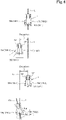
- the automatic travel control unit 60a causes the machine body 3 to perform a recovery movement such as to make the deviation between the position of the machine body 3 (machine body position) W1 detected by the position detecting device 50 and the planned travel route L less than a predetermined threshold when the machine body 3 is at a start point La of a straight section L1 or is about to enter the start point La of the straight section L1.
- the automatic travel control unit 60a causes the machine body 3 to travel rearward and forward to make a three-point turn (hereinafter referred to as a three-point-turn movement) to make the deviation less than the threshold at a position short of the start point La of the straight section L1 or at the start point La.
- the automatic travel control unit 60a causes the machine body 3 to perform a three-point-turn movement so that the angle ⁇ g is zero (the machine body heading direction F1 matches the direction of the planned travel route L).
- the automatic travel control unit 60a sets the angle of steering so that the deviation in direction ⁇ g approaches zero and switches the transmission 5 to rearward travel to cause the machine body 3 to travel a predetermined distance rearward (short rearward travel).
- the automatic travel control unit 60a sets the angle of steering so that the deviation in direction ⁇ g further approaches zero, and, as illustrated in the lower part of FIG. 5A , switches the transmission 5 to forward travel and causes the machine body 3 to travel a predetermined distance forward to move to the position short of the start point La of the straight section L1 or to the start point La (short forward travel).
- the automatic travel control unit 60a repeats the short rearward travel and the short forward travel until the deviation in direction ⁇ g from the straight section L1 is less than the threshold.
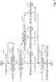
- the automatic travel control unit 60a determines, on the basis of the machine body position W1 and the planned travel route L, whether or not the machine body position W1 detected by the position detecting device 50 during automatic travel is located at a position short of a start point La of a straight section L1 or at the start point La (S1). If the automatic travel control unit 60a determines that the machine body position W1 is located at a position short of a start point La of a straight section L1 or at the start point La (Yes in S 1), the automatic travel control unit 60a determines whether or not the deviation in direction ⁇ g is equal to or greater than a threshold (S2).
- the automatic travel control unit 60a determines that the deviation in direction ⁇ g is equal to or greater than a threshold (Yes in S2), the automatic travel control unit 60a sets the angle of steering so that the deviation in direction ⁇ g approaches zero (S3), and switches the transmission 5 to rearward travel to cause the machine body 3 to travel a predetermined distance rearward (S4, short rearward travel). After causing the machine body 3 to travel a predetermined distance rearward (S4), the automatic travel control unit 60a sets the angle of steering so that the deviation in direction ⁇ g further approaches zero (S5), and switches the transmission 5 to forward travel and causes the machine body 3 to travel a predetermined distance forward to move to the position short of the start point La of the straight section L1 or to the start point La (S6, short forward travel).
- the flow proceeds to S2, and the automatic travel control unit 60a determines whether or not the deviation in direction ⁇ g is equal to or greater than the threshold (S2).
- the automatic travel control unit 60a repeats the short rearward travel and the short forward travel until the deviation in direction ⁇ g from the straight section L1 becomes less than the threshold.
- the automatic travel control unit 60a determines that the deviation in direction ⁇ g is less than the threshold (No in S2), the automatic travel control unit 60a ends the three-point-turn movement.
- the automatic travel control unit 60a may control the three-point-turn movement as follows: in the case where the deviation in position between the machine body position W1 and the planned travel route L at a position short of the start point La or at the start point La is equal to or greater than a threshold, the automatic travel control unit 60a sets the angle of steering so that the deviation in position is zero (the machine body heading direction F1 matches the direction of the planned travel route L).
- the automatic travel control unit 60a may control the three-point-turn movement by setting the angle of steering for automatic travel on the basis of an angle of steering determined on the basis of the deviation in position and an angle of steering determined on the basis of the deviation in direction.
- the three-point-turn movement (recovery movement) in automatic travel in the above-described embodiment is an example, and does not imply any limitation.
- the control device 60 includes a threshold setting unit 60b to set a threshold for the three-point-turn movement according to work.
- the work is, for example, work that can be done by the working device 2 linked to the raising/lowering device 8.
- the threshold setting unit 60b is composed of electrical/electronic circuit(s), program(s) stored in a CPU and/or the like, and/or the like.
- the threshold setting unit 60b is composed of electrical/electronic circuit(s) of the control device 60, program(s) stored in a CPU and/or the like of the control device 60, and/or the like in the present embodiment, the threshold setting unit 60b may be composed of electrical/electronic circuit(s) of some other apparatus other than the control device 60 such as the display device 30, program(s) stored in a CPU and/or the like of the apparatus, and/or the like.
- the working machine 1 includes selection member(s) 40 via which work can be selected.
- the threshold setting unit 60b sets a threshold according to the work selected via any of the selection member(s) 40.
- Work that can be selected via the selection member(s) 40 is, for example, work that can be done by the working device 2 linked to the raising/lowering device 8.
- work that can be selected via the selection member(s) 40 is, for example, work that can be done by the working device 2 linked to the raising/lowering device 8 in the present embodiment, the work that can be selected via the selection member(s) 40 is not limited to the work that can be done by the working device 2 linked to the raising/lowering device 8. As illustrated in FIG.
- the selection member(s) 40 is/are piece(s) of first graphics 40 displayed on the display unit 31, and an operator can select work by performing the operation to select any of the selection member(s) 40.
- the selection member(s) 40 is/are displayed on a selection screen M1 of the display unit 31.
- the display unit 31 displays the selection screen M1 upon a predetermined operation on the display device 30, and the selection screen M1 displays a plurality of selection members 40 corresponding to types of work.
- the selection members 40 indicate, as the types of work, work content (work categories) corresponding to working devices 2.
- the selection screen M1 also displays a first confirmation button 41 via which the selection of any of the selection members 40 is confirmed.
- selection members 40 need only make it possible to select work.
- the selection of work may be performed by selecting a working device instead of selecting work content (work category), and the method of the selection is not limited to the method as described above.
- the selection members 40 may be operation actuators (operation switches) which are provided on the display device 30 or the like and which are operable.
- the selection members 40 may be selection members 40 displayed on a PC or a mobile terminal such as a smartphone connected in a wireless or wired manner to the working machine 1.
- the selection members 40 are associated with the types of work, and the selection members 40 input operation information into the control device 60.
- the types of work that can be selected via the selection members 40 include first work and second work for which less work accuracy (accuracy of work) is required than for the first work.
- working devices 2 that can be selected via the selection members 40 include third work for which less work accuracy is required than for the first work but more work accuracy is required than for the second work, in addition to the first work and the second work.
- the first work to the third work correspond to one or more types of work content or one or more working devices.
- the first work includes seeding work done by a seeder
- the second work includes fertilization work done by a fertilizer spreader and/or stubble cultivation done by a stubble cultivator.
- the third work is, for example, cultivating work, which is work other than at least the seeding work, the fertilization work, and the stubble cultivation, and work for which less work accuracy is required than for the seeding work but more work accuracy is required than for the fertilization work and the stubble cultivation.
- the selection members 40 (pieces of first graphics 40) displayed on the selection screen M1 of the display unit 31 include a first selection item 40a, a second selection item 40b, a third selection item 40c, and a fourth selection item 40d.
- the first selection item 40a corresponds to the seeding work which is the first work, and displays "seeding" which is the name corresponding to the seeding work.
- the second selection item 40b corresponds to the fertilization work which is the second work, and displays "fertilization” which is the name corresponding to the fertilization work.
- the third selection item 40c corresponds to stubble cultivation which is the second work, and displays the "stubble cultivation” which is the name corresponding to the stubble cultivation.
- the fourth selection item 40d corresponds to the cultivating work which is the third work, and displays "cultivation" which is the name corresponding to the cultivating work.
- the types of work that can be selected via the selection members 40 need only include at least first work and second work for which less work accuracy is required than for the first work, and the types of work that can be selected via the selection members 40 are not limited to the above-described types, and the categories thereof are not limited to the above-described categories.
- the first work may include spreading work done by a spreader
- the second work may include work to be done against the ground done by a ground implement.
- the first work is seeding work done by a seeder, agricultural chemical spreading done by an agricultural chemical spreader, or the like which is a type of spreading work
- the second work is stubble cultivation and cultivating work and/or the like.
- the threshold setting unit 60b acquires a threshold from the storage device 32 on the basis of the operation of any of the selection members 40, and sets the acquired threshold as a threshold for the three-point-turn movement.
- the thresholds include a first threshold (e.g., 1 degree) corresponding to the first work and a second threshold (for example, 3 degrees) which corresponds to the second work and which is greater than the first threshold (the second threshold > the first threshold).
- the storage device 32 stores operation on each selection member 40, i.e., each type of work, and a threshold such that the work and the threshold are associated with each other, and stores the first threshold and the second threshold.
- the thresholds include, in addition to the first threshold and the second threshold, a third threshold (e.g., 2 degrees) which differs from the first threshold and the second threshold and which corresponds to the third work.
- the third threshold is greater than the first threshold and is less than the second threshold (first threshold ⁇ third threshold ⁇ second threshold).
- the storage device 32 stores the first threshold, the second threshold, and the third threshold such that the first work is associated with the first threshold, the second work is associated with the second threshold, and the third work is associated with the third threshold.
- the threshold setting unit 60b acquires the first threshold from the storage device 32 and sets the first threshold as a threshold for the three-point-turn movement.
- operation information of the second selection item 40b or the third selection item 40c is inputted into the threshold setting unit 60b from the display device 30, and the threshold setting unit 60b acquires the second threshold from the storage device 32 and sets the second threshold as a threshold for the three-point-turn movement.
- operation information of the third selection item 40c is inputted into the threshold setting unit 60b from the display device 30, and the threshold setting unit 60b acquires the third threshold from the storage device 32 and sets the third threshold as a threshold for the three-point-turn movement.
- the thresholds need only include values corresponding to types of work that can be selected via the selection members 40, and the values are not limited to the first threshold and the second threshold.
- the thresholds may include the foregoing third threshold.
- the thresholds include a fourth threshold in addition to the first to third thresholds.
- the working machine 1 may include an input device 30 capable of receiving input of work accuracy, and the threshold setting unit 60b may correct a threshold according to the work accuracy inputted into the input device 30.
- the input device 30 is a device which is connected to the threshold setting unit 60b (control device 60) communicably in a wired or wireless manner and which is capable of receiving input of work accuracy.
- the input device 30 is the display device 30, and work accuracy can be inputted by selecting any of pieces of second graphics 45 displayed on the display unit 31.
- the input device 30 is not limited to the display device 30, and the input device 30 may be an operation actuator which is provided on the working machine 1 and which is operable or a PC or a mobile terminal such as a smartphone communicably connected to the working machine 1 in a wireless or wired manner.
- the input device 30 does not imply any limitation.
- the input device 30 displays, on the display unit 31, the pieces of second graphics 45 which correspond to work accuracies and which are selectable and operable. Upon operation of any of the pieces of second graphics 45, a corresponding work accuracy is inputted into the threshold setting unit 60b.
- the pieces of second graphics 45 are displayed on an input screen M2 of the display unit 31.
- the display unit 31 displays the input screen M2 upon operation to select one of the selection members 40 on the selection screen M1, and the plurality of pieces of second graphics 45 corresponding to work accuracies are displayed on the input screen M2.
- the input screen M2 displays a second confirmation button 46 via which the input of a work accuracy is confirmed.
- the pieces of second graphics 45 indicate work accuracies corresponding to the first to third thresholds.
- the display device 30 includes, for example, a first input item 45a with "high accuracy” corresponding to the first threshold, a second input item 45b with “high efficiency” corresponding to the second threshold, and a third input item 45c with "normal” corresponding to the third threshold.
- the input screen M2 displays the pieces of second graphics 45 such that a piece of second graphics 45 corresponding to the threshold (one of the first to third thresholds) set by the threshold setting unit 60b is preselected.
- the second confirmation button 46 Upon operation of the second confirmation button 46 by an operator, the selection of the selected piece of second graphics 45 is confirmed.
- the input screen M2 displays the first input item 45a corresponding to the first threshold in a preselected manner.
- the input screen M2 displays the second input item 45b corresponding to the second threshold in a preselected manner.
- the input screen M2 displays the third input item 45c corresponding to the third threshold in a preselected manner.
- the input device 30 inputs the work accuracy into the threshold setting unit 60b on the basis of the operation to select the selected piece of second graphics 45.
- the storage device 32 stores work accuracies inputted from the input device 30 and thresholds such that the work accuracies are associated with the thresholds.
- the threshold setting unit 60b acquires a threshold from the storage device 32 on the basis of the work accuracy inputted from the input device 30, and corrects the acquired threshold as a threshold for the three-point-turn movement.
- a work accuracy corresponding to the first input item 45a is inputted from the input device 30 into the threshold setting unit 60b, and the threshold setting unit 60b acquires the first threshold from the storage device 32 and corrects the first threshold as a threshold for the three-point-turn movement.
- a work accuracy corresponding to the second input item 45b or the third input item 45c is inputted from the input device 30 into the threshold setting unit 60b, and the threshold setting unit 60b acquires the second threshold from the storage device 32 and corrects the second threshold as a threshold for the three-point-turn movement.
- a work accuracy corresponding to the fourth input item is inputted from the input device 30 into the threshold setting unit 60b, and the threshold setting unit 60b acquires the third threshold from the storage device 32 and corrects the third threshold as a threshold for the three-point-turn movement.
- the threshold setting unit 60b need only correct a threshold on the basis of the work accuracy inputted from the input device 30, that the thresholds to be corrected are not limited to the first to third thresholds and may be different values, and that a method of correction is not limited to that described above.
- the threshold setting unit 60b may correct a threshold by multiplying a threshold acquired from the storage device 32 on the basis of the operation of one of the selection members 40 by a predetermined correction value ⁇ based on the work accuracy inputted from the input device 30.
- the correction value ⁇ for the second input item 45b (high accuracy) is 0.8
- the correction value ⁇ for the second input item 45b (high efficiency) is 1.2
- the correction value ⁇ for the third input item 45c (normal) is 1.0
- the correction values ⁇ are stored in the storage device 32 such that the correction values ⁇ are associated with the work accuracies inputted from the input device 30.
- the values of the correction values ⁇ are mere examples, and not limited to the values described above.
- the threshold setting unit 60b sets a threshold for the three-point-turn movement.
- the display unit 31 displays the selection screen M1 (S11).
- the threshold setting unit 60b determines whether or not any of the selection members 40 has been operated and the first confirmation button 41 has been operated (S12).
- the threshold setting unit 60b determines that a selection member 40 has been operated and the first confirmation button 41 has been operated (Yes in S12), and determines whether or not the operated selection member 40 is a selection member 40 corresponding to the second work (S13).
- the threshold setting unit 60b determines whether or not the operated selection member 40 is the second selection item 40b corresponding to fertilization work or the third selection item 40c corresponding to stubble cultivation.
- the threshold setting unit 60b determines that the operated selection member 40 is a selection member 40 corresponding to the second work (the second selection item 40b or the third selection item 40c) (Yes in S13)
- the threshold setting unit 60b acquires the second threshold corresponding to the second work from the storage device 32 and sets the acquired second threshold as a threshold for the three-point-turn movement (S14).
- the display unit 31 displays the input screen M2 in which the piece of second graphics 45 corresponding to the second threshold (second input item 45b) is displayed in a preselected manner (S15). Once the display unit 31 has displayed the input screen M2 (S15), the threshold setting unit 60b determines whether or not the second confirmation button 46 has been operated (S16).
- the threshold setting unit 60b acquires, from the storage device 32, a threshold corresponding to the piece of second graphics 45 corresponding to the work accuracy inputted into the input device (display device 30), i.e., a threshold corresponding to the piece of second graphics 45 selected by operation, and corrects the acquired threshold as a threshold for the three-point-turn movement (S17).
- the threshold setting unit 60b determines whether or not the operated selection member 40 is a selection member 40 corresponding to the first work (S18). Specifically, the threshold setting unit 60b determines whether or not the operated selection member 40 is the first selection item 40a corresponding to seeding work.
- the threshold setting unit 60b determines that the operated selection member 40 is the selection member 40 corresponding to the first work (first selection item 40a) (Yes in S18), the threshold setting unit 60b acquires the first threshold corresponding to the first work from the storage device 32, and sets the acquired first threshold as a threshold for the three-point-turn movement (S19).
- the display unit 31 displays the input screen M2 in which the piece of second graphics 45 corresponding to the first threshold (first input item 45a) is displayed in a preselected manner (S20). Once the display unit 31 has displayed the input screen M2 (S20), the flow proceeds to S16, and the threshold setting unit 60b determines whether or not the second confirmation button 46 has been operated (S16).
- the threshold setting unit 60b determines that the operated selection member 40 is not the selection member 40 corresponding to the first work (not the first selection item 40a) (No in S18), that is, if the operated selection member 40 is a selection member 40 corresponding to the third work (fourth selection item 40d), the threshold setting unit 60b acquires the third threshold corresponding to the third work from the storage device 32, and sets the acquired third threshold as a threshold for the three-point-turn movement (S21).
- the display unit 31 displays the input screen M2 in which the piece of second graphics 45 corresponding to the third threshold (third input item 45c) is displayed in a preselected manner (S22). Once the display unit 31 has displayed the input screen M2 (S22), the flow proceeds to S16, and the threshold setting unit 60b determines whether or not the second confirmation button 46 has been operated (S16).
- a working machine 1 as has been described includes a machine body 3 capable of traveling, a position detecting device 50 to detect a machine body position W1, and a control device 60 to control the machine body 3 on the basis of the machine body position W1 detected by the position detecting device 50 and a planned travel route L, wherein the planned travel route L includes a plurality of straight sections L1 on which the machine body 3 travels straight, and the control device 60 includes a threshold setting unit 60b to set a threshold according to work, and causes the machine body 3 to perform a recovery movement such as to make a deviation between the machine body position W1 detected by the position detecting device 50 and the planned travel route L less than the threshold when the machine body 3 is at a start point La of any of the straight sections L1 or is about to enter the start point La of the straight section L1.
- the threshold setting unit 60b sets a threshold for each work done by the working machine 1. This makes it possible for the working machine 1 to adjust work efficiency and work accuracy according to the content, category, or the like of work.
- the working machine 1 further includes at least one selection member 40 via which the work is capable of being selected, wherein the threshold setting unit 60b sets the threshold according to the work selected via the at least one selection member 40.
- the threshold setting unit 60b sets a first threshold as the threshold upon selection of the first work via the at least one selection member 40; and a second threshold as the threshold upon selection of the second work via the at least one selection member 40, the second threshold being greater than the first threshold.
- the first work includes spreading work done by a spreader
- the second work includes work against a ground done by a ground implement.
- the first work includes seeding work done by a seeder
- the second work includes fertilization work done by a fertilizer spreader and/or stubble cultivation performed by a stubble cultivator.
- the working machine 1 further includes an input device 30 capable of receiving input of accuracy of the work, wherein the threshold setting unit 60b sets the threshold according to the work and corrects the threshold according to the accuracy of the work inputted into the input device 30.
- This configuration makes it possible to correct (change) the threshold as needed in addition to the working device 2, and possible to improve convenience.
- the recovery movement is a movement in which the machine body 3 makes a three-point turn.
- the three-point-turn movement of the machine body 3 may result in, for example, a decrease in work efficiency and large consumption of a power source such as fuel or battery of the machine body 3.
- the working machine 1 performs automatic travel according to the planned travel route L in the foregoing embodiment, the working machine 1 may be configured such that automatic steering is performed without performing control of travel speed according to the planned travel route L.
Landscapes
- Engineering & Computer Science (AREA)
- Radar, Positioning & Navigation (AREA)
- Remote Sensing (AREA)
- Life Sciences & Earth Sciences (AREA)
- Automation & Control Theory (AREA)
- General Physics & Mathematics (AREA)
- Physics & Mathematics (AREA)
- Aviation & Aerospace Engineering (AREA)
- Mechanical Engineering (AREA)
- Soil Sciences (AREA)
- Environmental Sciences (AREA)
- Guiding Agricultural Machines (AREA)
- Control Of Position, Course, Altitude, Or Attitude Of Moving Bodies (AREA)
- Lifting Devices For Agricultural Implements (AREA)
Abstract
Description
- The present invention relates to a working machine which travels according to a planned travel route.
- Conventionally, a working machine disclosed in
Patent document 1 includes a machine body capable of traveling, a working device mounted on the machine body, a position detecting device to detect the position of a machine body, and a control device to control the machine body on the basis of the position of the machine body detected by the position detecting device and a planned travel route. - [Patent document 1]
Japanese Unexamined Patent Application Publication No. 2019-126280 - The working machine of
Patent document 1 is capable of traveling along a planned travel route. - However, the control device performs control so that the deviation between the machine body and the planned travel route is eliminated both in the case where travel accuracy is required given the type of work done by the working device and in the case where the travel accuracy is not required given the type of the work. Therefore, work efficiency may decrease in the case of work for which accuracy is not required.
- The present invention was made in order to solve such an issue of the conventional technique, and an object thereof is to provide a working machine that is capable of efficiently traveling according to work accuracy.
- A working machine according to an aspect of the present invention includes a machine body capable of traveling, a position detecting device to detect a position of the machine body, and a control device to control the machine body on the basis of the position of the machine body detected by the position detecting device and a planned travel route, wherein the planned travel route includes a straight section on which the machine body travels straight, and the control device includes a threshold setting unit to set a threshold according to work, and causes the machine body to perform a recovery movement such as to make a deviation between the position of the machine body detected by the position detecting device and the planned travel route less than the threshold when the machine body is at a start point of the straight section or is about to enter the start point of the straight section.
- The working machine further includes at least one selection member via which the work is capable of being selected, wherein the threshold setting unit sets the threshold according to the work selected via the at least one selection member.
- First work and second work for which less work accuracy is required than for the first work are capable of being selected via the at least one selection member, the threshold setting unit sets first threshold as the threshold upon selection of the first work via the at least one selection member, and a second threshold as the threshold upon selection of the second work via the at least one selection member, the second threshold being greater than the first threshold.
- The first work includes spreading work done by a spreader and the second work includes work against a ground done by a ground implement.
- The first work includes seeding work done by a seeder, and the second work includes fertilization work done by a fertilizer spreader and/or stubble cultivation performed by a stubble cultivator.
- The working machine further includes an input device capable of receiving input of accuracy of the work, wherein the threshold setting unit sets the threshold according to the work and corrects the threshold according to the accuracy of the work inputted into the input device.
- The recovery movement is a movement in which the machine body makes a three-point turn.
- The above-described working machine is capable of efficiently traveling according to work accuracy.
-
-
FIG. 1 is a block diagram of a working machine. -
FIG. 2 illustrates a raising/lowering device. -
FIG. 3 illustrates how the working machine performs automatic travel. -
FIG. 4 illustrates automatic travel. -
FIG. 5A illustrates a three-point-turn movement of the working machine. -
FIG. 5B is a chart showing a flow of the three-point-turn movement of the working machine. -
FIG. 6A illustrates an example of a selection screen displayed on a display unit. -
FIG. 6B illustrates an example of an accuracy selection screen displayed on the display unit. -
FIG. 7 is a chart showing a flow in which a threshold setting unit sets a threshold. -
FIG. 8 is a general side view of the working machine. - The following description discusses an embodiment of the present invention with reference to drawings.
- First, a working
machine 1 is discussed. The workingmachine 1 includes a workingdevice 2 to do work, and is, for example, an agricultural machine such as a tractor, a combine, or a rice transplanter. The present embodiment is discussed based on the assumption that theworking vehicle 1 is a tractor. As illustrated inFIG. 8 , theworking machine 1 includes a machine body (travel vehicle) 3 capable of traveling, aprime mover 4, atransmission 5, and theworking device 2. Themachine body 3 is provided with an operator'sseat 10. In the following description, the front of the working machine 1 (as indicated by arrow A1 inFIG. 8 ) as seen from an operator seated on the operator'sseat 10 is "front", the rear of the working machine 1 (as indicated by arrow A2 inFIG. 8 ) as seen from the operator is "rear", the left side of the working machine 1 (near side inFIG. 8 ) as seen from the operator is "left", and the right side of the working machine 1 (far side inFIG. 8 ) as seen from the operator is "right". - The
machine body 3 includes atraveling device 7. Thetraveling device 7 includes wheels which rotate (front wheel(s) 7F and rear wheel(s) 7R). Thefront wheels 7F may be tire-shaped wheels and may be crawler-shaped wheels. Therear wheels 7R also may be tire-shaped wheels and may be crawler-shaped wheels. - The
prime mover 4 is a diesel engine, an electric motor, and/or the like. Thetransmission 5 is capable of changing driving forces for thetraveling device 7 by changing speed stages and switching the traveling state of the travelingdevice 7 between forward and rearward traveling states. In the present embodiment, thetransmission 5 is a continuously variable transmission, in particular, a hydraulic mechanical transmission (HMT). Themachine body 3 includes an output shaft (PTO shaft) 6 which transmits power from theprime mover 4. Theoutput shaft 6 projects rearward from the rear of themachine body 3. - Furthermore, as illustrated in
FIG. 8 , themachine body 3 has a raising/loweringdevice 8 to which theworking device 2 can be detachably attached and which is capable of raising and lowering theworking device 2. Specifically, themachine body 3 is provided with, at the rear thereof, the raising/loweringdevice 8 composed of a three-point linkage or the like. This makes it possible to link theworking device 2 to themachine body 3. By linking theworking device 2 to the raising/loweringdevice 8, it is possible to allow themachine body 3 to tow theworking device 2. - The
working device 2 is mounted on themachine body 3 via, for example, the raising/loweringdevice 8. The workingdevice 2 is a digger for digging potatoes and/or carrots, a spreader such as a fertilizer spreader (fertilizing device) for spreading fertilizer or an agricultural chemical spreader for spreading agricultural chemicals, a seeder for seeding on an agricultural field, a harvester for harvesting, a digger for mowing grass or the like, a tedder for tedding grass or the like, a rake for raking grass or the like, a baler for baling grass or the like, a ground implement which does work against an agricultural field, or the like. The ground implement encompasses a stubble cultivator for stubble cultivation, a harrow for puddling, a cultivator (rotary cultivator) for cultivating work, and the like. - As illustrated in
FIG. 1 , theworking machine 1 includes asteering unit 11. Thesteering unit 11 includes asteering wheel 11a, a rotation shaft (steering shaft) 11b which rotates as thesteering wheel 11a rotates, and an assist mechanism (power steering mechanism) 11c to assist steering performed using thesteering wheel 11a. Theassist mechanism 11c includes ahydraulic pump 12, acontrol valve 13 supplied with hydraulic fluid discharged from thehydraulic pump 12, and asteering cylinder 14 which is caused to function by thecontrol valve 13. Thecontrol valve 13 is a solenoid valve which functions according to a control signal. Thecontrol valve 13 is, for example, a three-way switching valve which achieves multi-position switching by movement of a spool or the like. The positions of thecontrol valve 13 can also be switched by steering by therotation shaft 11b. Thesteering cylinder 14 is connected to arms (knuckle arms) 15 which change the orientation of thefront wheels 7F. - Therefore, upon operation of the
steering wheel 11a, the position and the degree of opening of thecontrol valve 13 change according to thesteering wheel 11a, and thesteering cylinder 14 extends or retracts leftward or rightward according to the position and the degree of opening of thecontrol valve 13, making it possible to change the steering direction of thefront wheels 7F. Note that the foregoingsteering unit 11 is an example, and the foregoing configuration does not imply limitation. - The raising/lowering
device 8 is described in detail. As illustrated inFIG. 2 , the raising/loweringdevice 8 includes liftarms 8a,lower links 8b, atop link 8c,lift rods 8d, and liftcylinders 8e, and is capable of raising and lowering the workingdevice 2. As illustrated inFIG. 1 , a front end of eachlift arm 8a is supported on an upper rear portion of a case (transmission case) housing thetransmission 5 such that thelift arm 8a is swingable up and down. Thelift arm 8a is driven by acorresponding lift cylinder 8e to swing (raised or lowered). Thelift cylinder 8e is composed of a hydraulic cylinder. Thelift cylinder 8e is connected to the hydraulic pump12 via thecontrol valve 16. Thecontrol valve 16 is a solenoid valve or the like to cause thelift cylinder 8e to extend and retract. - As illustrated in
FIG. 1 , a front end of eachlower link 8b is supported on a lower rear portion of thetransmission 5 such that thelower link 8b is swingable up and down. A front end of thetop link 8c is supported, at a position higher than thelower link 8b, on a rear portion of thetransmission 5 such that thetop link 8c is swingable up and down. Eachlift rod 8d connects acorresponding lift arm 8a and a correspondinglower link 8b. The workingdevice 2 is linked to rear portions of thelower links 8b and thetop link 8c. When thelift cylinders 8e are driven (extend or retract), thelift arms 8a ascend or descend, and thelower links 8b connected to thelift arms 8a via thelift rods 8d also ascend or descend. With this, the raising/loweringdevice 8 is capable of switching between a non-working position in which the workingdevice 2 is in a raised position and a working position in which the workingdevice 2 is in a lowered position, and the workingdevice 2 swings up or down (raised or lowered) about front portions of thelower links 8b. - As illustrated in
FIG. 1 , the workingmachine 1 includes adisplay device 30. Thedisplay device 30 includes adisplay unit 31 composed of a liquid crystal panel, a touchscreen, or some other panel, and astorage device 32. Thedisplay unit 31 is configured to display not only information to assist the workingmachine 1 in traveling but also various types of information regarding the workingmachine 1. Thestorage device 32 is a nonvolatile memory and/or the like, and stores, for example, information to be displayed on thedisplay unit 31. Furthermore, thedisplay device 30 is connected to apparatus(es) of the workingmachine 1 communicably in a wired or wireless manner. - As illustrated in
FIG. 3 , the workingmachine 1 is capable of performing automatic travel according to a predetermined planned travel route L and raising and lowering the workingdevice 2 via the raising/loweringdevice 8. - As illustrated in
FIG. 1 , the workingmachine 1 includes aposition detecting device 50. Theposition detecting device 50 is a device to detect the position of themachine body 3. In the present embodiment, theposition detecting device 50 is, for example, a positioning device. Theposition detecting device 50 is capable of detecting the position thereof (measured position information including latitude and longitude) by a satellite positioning system (positioning satellites G) such as D-GPS, GPS, GLONASS, BeiDou, Galileo, and/or Michibiki. Specifically, theposition detecting device 50 receives satellite signals (positions of positioning satellites G, time of transmission, correction information, and/or the like) from the positioning satellites G, and detects the position (e.g., latitude and longitude) of the working machine 1 (machine body 3), i.e., a machine body position W1, on the basis of the satellite signals. As illustrated inFIG. 1 , theposition detecting device 50 includes areceiver 51 and an inertial measurement unit (IMU) 52. Thereceiver 51 is a device which includes an antenna and/or the like and which receives satellite signals from the positioning satellites G, and is attached to themachine body 3 independently of theinertial measurement unit 52. In the present embodiment, thereceiver 51 is attached to an upper portion of a cabin (protection mechanism) 9 provided on themachine body 3. Note that the location at which thereceiver 51 is attached is not limited to that described above, and may be a central portion of a hood. In the case where a ROPS is provided on themachine body 3, thereceiver 51 may be attached to an upper portion of the ROPS. - The
inertial measurement unit 52 includes an acceleration sensor to detect the acceleration α of themachine body 3, a gyroscope sensor to detect the angular velocity of themachine body 3, and/or the like. Theinertial measurement unit 52 is provided on themachine body 3, for example, below the operator'sseat 10, and is capable of detecting the roll angle, pitch angle, yaw angle, and/or the like of themachine body 3. - Note that, although the
position detecting device 50 in the present embodiment is aposition detecting device 50 that detects the position of themachine body 3 on the basis of satellite signals, theposition detecting device 50 is not limited to the configuration as described above, provided that theposition detecting device 50 is capable of detecting the position of themachine body 3. Theposition detecting device 50 may be one that detects the position of themachine body 3 on the basis of the acceleration α detected by theinertial measurement unit 52 and prescribed position information. - As illustrated in
FIG. 1 , the workingmachine 1 includes acontrol device 60 and a storage unit 62. Thecontrol device 60 is a device to control a traveling system of the workingmachine 1, control a working system of the workingmachine 1, and/or the like. The storage unit 62 is a nonvolatile memory and/or the like, and stores various types of information regarding control by thecontrol device 60. - As illustrated in
FIG. 1 , thesteering unit 11 includes an auto-steerer 17. The auto-steerer 17 is a mechanism to perform automatic steering of themachine body 3, and automatically steers themachine body 3 on the basis of a planned travel route L and a machine body position W1 detected by theposition detecting device 50. The auto-steerer 17 includes a steering motor 17a and agear mechanism 17b. The steering motor 17a is a motor whose direction of rotation, speed of rotation, angle of rotation, and/or the like can be controlled on the basis of the machine body position W1. Thegear mechanism 17b includes a gear which is provided on therotation shaft 11b and which rotates together with therotation shaft 11b, and a gear which is provided on therotation shaft 11b of the steering motor 17a and which rotates together with therotation shaft 11b. As therotation shaft 11b of the steering motor 17a rotates, therotation shaft 11b automatically rotates (pivots) via thegear mechanism 17b, making it possible to change the steering direction of thefront wheels 7F so that the machine body position W1 matches the planned travel route L. - As illustrated in
FIG. 1 , thecontrol device 60 includes an automatictravel control unit 60a to control themachine body 3 on the basis of the machine body position W1 detected by theposition detecting device 50 and the planned travel route L, that is, control the automatic travel of the workingmachine 1. The automatictravel control unit 60a is composed of electrical/electronic circuit(s) in thecontrol device 60, program(s) stored in a CPU and/or the like in thecontrol device 60, and/or the like. The automatictravel control unit 60a is capable of controlling the speed stage of thetransmission 5, the rotation speed of theprime mover 4, the auto-steerer 17, and the like, and controls the automatic travel of themachine body 3 on the basis of the machine body position W1 detected by theposition detecting device 50 and the planned travel route L. - The automatic
travel control unit 60a controls, after the start of automatic travel, the steering motor 17a so that themachine body 3 travels along the planned travel route L. The automatictravel control unit 60a, after the start of automatic travel, automatically changes the speed stage of thetransmission 5, the rotation speed of theprime mover 4, and/or the like to control the vehicle speed (travel speed) of the workingmachine 1. - As illustrated in
FIG. 3 , the planned travel route L includes a plurality of straight sections L1 on which themachine body 3 travels straight. The planned travel route L also includes connecting section(s) L2 each of which connects an end point Lb of one of the plurality of straight sections L1 and a start point La of another of the plurality of straight sections L1. In the present embodiment, the connecting sections L2 are turn sections on which themachine body 3 turns. The automatictravel control unit 60a, after the start of automatic travel, performs control so that different travel speeds are used in the straight sections L1 and the turn sections L2, respectively. For example, in the straight sections L1, the automatictravel control unit 60a sets the travel speed to a speed v1. On the other hand, in the turn sections L2, the automatictravel control unit 60a sets the travel speed to a speed v2 that is lower than the speed v1 (v2 is greater than v1). Note that any of the straight sections L1 may be divided into a plurality of segments and the automatictravel control unit 60a may set different travel speeds in the respective segments. The control of the travel speed is not limited to the above-described configuration. - Furthermore, the automatic
travel control unit 60a, after the start of automatic travel, controls the raising/loweringdevice 8 to be in different positions in the straight sections L1 and the turn sections L2, respectively. For example, in the straight sections L1, the automatictravel control unit 60a sets the raising/loweringdevice 8 to be in a working position. On the other hand, in the turn sections L2, the automatictravel control unit 60a sets the raising/loweringdevice 8 to be in a non-working position. - As illustrated in
FIG. 4 , under the conditions in which the workingmachine 1 is performing automatic travel, the automatictravel control unit 60a performs control so that themachine body 3 travels along the planned travel route L. That is, if the deviation between themachine body 3 and the planned travel route L is less than a predetermined set value, the automatictravel control unit 60a maintains the angle of rotation of therotation shaft 11b. If the deviation between themachine body 3 and the planned travel route L is equal to or greater than the set value, the automatictravel control unit 60a causes therotation shaft 11b to rotate so that the deviation is zero. - Specifically, if the deviation (deviation in position) between the machine body position W1 and the planned travel route L is less than a predetermined set value, the automatic
travel control unit 60a maintains the angle of rotation of therotation shaft 11b. On the contrary, if the deviation in position between the machine body position W1 and the planned travel route L is equal to or greater than the set value and the workingmachine 1 is positioned leftward of the planned travel route L, the automatictravel control unit 60a causes therotation shaft 11b to rotate so that the workingmachine 1 is steered right. If the deviation in position between the machine body position W1 and the planned travel route L is equal to or greater than the set value and the workingmachine 1 is positioned rightward of the planned travel route L, the automatictravel control unit 60a causes therotation shaft 11b to rotate so that the workingmachine 1 is steered left. - Note that, although the angle of steering by the
steering unit 11 is changed on the basis of the deviation in position between the machine body position W1 and the planned travel route L in the above embodiment, the automatictravel control unit 60a may, in the case where the direction of the planned travel route L and the travel direction of the working machine 1 (machine body 3) (machine body heading direction) F1 differ from each other, i.e., in the case where an angle (deviation in direction) θg of the machine body heading direction F1 to the planned travel route L is equal to or greater than a set value, set the angle of steering so that the angle θg is zero (the machine body heading direction F1 matches the direction of the planned travel route L). The automatictravel control unit 60a may set the final angle of steering for the automatic travel on the basis of an angle of steering determined based on the deviation (deviation in position) and an angle of steering determined based on directions (deviation in direction). Settings of the angle of steering in automatic travel in the above-described embodiment are examples, and do not imply any limitation. - As illustrated in
FIG. 5A , the automatictravel control unit 60a causes themachine body 3 to perform a recovery movement such as to make the deviation between the position of the machine body 3 (machine body position) W1 detected by theposition detecting device 50 and the planned travel route L less than a predetermined threshold when themachine body 3 is at a start point La of a straight section L1 or is about to enter the start point La of the straight section L1. Specifically, the automatictravel control unit 60a causes themachine body 3 to travel rearward and forward to make a three-point turn (hereinafter referred to as a three-point-turn movement) to make the deviation less than the threshold at a position short of the start point La of the straight section L1 or at the start point La. In the present embodiment, if the angle (deviation in direction) θg of the machine body heading direction F1 to the straight section L1 is equal to or greater than the threshold, the automatictravel control unit 60a causes themachine body 3 to perform a three-point-turn movement so that the angle θg is zero (the machine body heading direction F1 matches the direction of the planned travel route L). - Specifically, when the machine body position W1 is located at a position short of the start point La of the straight section L1 or located at the start point La and the deviation in direction θg is equal to or greater than a threshold, as illustrated in the middle part of
FIG. 5A , the automatictravel control unit 60a sets the angle of steering so that the deviation in direction θg approaches zero and switches thetransmission 5 to rearward travel to cause themachine body 3 to travel a predetermined distance rearward (short rearward travel). - Furthermore, after causing the
machine body 3 to travel a predetermined distance rearward, the automatictravel control unit 60a sets the angle of steering so that the deviation in direction θg further approaches zero, and, as illustrated in the lower part ofFIG. 5A , switches thetransmission 5 to forward travel and causes themachine body 3 to travel a predetermined distance forward to move to the position short of the start point La of the straight section L1 or to the start point La (short forward travel). The automatictravel control unit 60a repeats the short rearward travel and the short forward travel until the deviation in direction θg from the straight section L1 is less than the threshold. - A flow of the three-point-turn movement of the
machine body 3 caused by the automatictravel control unit 60a is discussed. As shown inFIG. 5B , the automatictravel control unit 60a determines, on the basis of the machine body position W1 and the planned travel route L, whether or not the machine body position W1 detected by theposition detecting device 50 during automatic travel is located at a position short of a start point La of a straight section L1 or at the start point La (S1). If the automatictravel control unit 60a determines that the machine body position W1 is located at a position short of a start point La of a straight section L1 or at the start point La (Yes in S 1), the automatictravel control unit 60a determines whether or not the deviation in direction θg is equal to or greater than a threshold (S2). If the automatictravel control unit 60a determines that the deviation in direction θg is equal to or greater than a threshold (Yes in S2), the automatictravel control unit 60a sets the angle of steering so that the deviation in direction θg approaches zero (S3), and switches thetransmission 5 to rearward travel to cause themachine body 3 to travel a predetermined distance rearward (S4, short rearward travel). After causing themachine body 3 to travel a predetermined distance rearward (S4), the automatictravel control unit 60a sets the angle of steering so that the deviation in direction θg further approaches zero (S5), and switches thetransmission 5 to forward travel and causes themachine body 3 to travel a predetermined distance forward to move to the position short of the start point La of the straight section L1 or to the start point La (S6, short forward travel). - After the automatic
travel control unit 60a has caused themachine body 3 to travel a predetermined distance rearward (S4), the flow proceeds to S2, and the automatictravel control unit 60a determines whether or not the deviation in direction θg is equal to or greater than the threshold (S2). Thus, the automatictravel control unit 60a repeats the short rearward travel and the short forward travel until the deviation in direction θg from the straight section L1 becomes less than the threshold. - If the automatic
travel control unit 60a determines that the deviation in direction θg is less than the threshold (No in S2), the automatictravel control unit 60a ends the three-point-turn movement. - Note that, although the working
machine 1 performs the three-point-turn movement on the basis of the angle (deviation in direction) θg of the machine body headingdirection F 1 to the planned travel route L in the above-described embodiment, the method for the three-point-turn movement is not limited to that described above. The automatictravel control unit 60a may control the three-point-turn movement as follows: in the case where the deviation in position between the machine body position W1 and the planned travel route L at a position short of the start point La or at the start point La is equal to or greater than a threshold, the automatictravel control unit 60a sets the angle of steering so that the deviation in position is zero (the machine body heading direction F1 matches the direction of the planned travel route L). The automatictravel control unit 60a may control the three-point-turn movement by setting the angle of steering for automatic travel on the basis of an angle of steering determined on the basis of the deviation in position and an angle of steering determined on the basis of the deviation in direction. The three-point-turn movement (recovery movement) in automatic travel in the above-described embodiment is an example, and does not imply any limitation. - As illustrated in
FIG. 1 , thecontrol device 60 includes athreshold setting unit 60b to set a threshold for the three-point-turn movement according to work. The work is, for example, work that can be done by the workingdevice 2 linked to the raising/loweringdevice 8. Thethreshold setting unit 60b is composed of electrical/electronic circuit(s), program(s) stored in a CPU and/or the like, and/or the like. Note that, although thethreshold setting unit 60b is composed of electrical/electronic circuit(s) of thecontrol device 60, program(s) stored in a CPU and/or the like of thecontrol device 60, and/or the like in the present embodiment, thethreshold setting unit 60b may be composed of electrical/electronic circuit(s) of some other apparatus other than thecontrol device 60 such as thedisplay device 30, program(s) stored in a CPU and/or the like of the apparatus, and/or the like. - The working
machine 1 includes selection member(s) 40 via which work can be selected. Thethreshold setting unit 60b sets a threshold according to the work selected via any of the selection member(s) 40. Work that can be selected via the selection member(s) 40 is, for example, work that can be done by the workingdevice 2 linked to the raising/loweringdevice 8. Note that, although work that can be selected via the selection member(s) 40 is, for example, work that can be done by the workingdevice 2 linked to the raising/loweringdevice 8 in the present embodiment, the work that can be selected via the selection member(s) 40 is not limited to the work that can be done by the workingdevice 2 linked to the raising/loweringdevice 8. As illustrated inFIG. 6A , in the present embodiment, the selection member(s) 40 is/are piece(s) offirst graphics 40 displayed on thedisplay unit 31, and an operator can select work by performing the operation to select any of the selection member(s) 40. The selection member(s) 40 is/are displayed on a selection screen M1 of thedisplay unit 31. Thedisplay unit 31 displays the selection screen M1 upon a predetermined operation on thedisplay device 30, and the selection screen M1 displays a plurality ofselection members 40 corresponding to types of work. In the present embodiment, theselection members 40 indicate, as the types of work, work content (work categories) corresponding to workingdevices 2. The selection screen M1 also displays afirst confirmation button 41 via which the selection of any of theselection members 40 is confirmed. - Note that the
selection members 40 need only make it possible to select work. The selection of work may be performed by selecting a working device instead of selecting work content (work category), and the method of the selection is not limited to the method as described above. - In the case where the
display device 30 is not an operable touchscreen or the like, theselection members 40 may be operation actuators (operation switches) which are provided on thedisplay device 30 or the like and which are operable. Theselection members 40 may beselection members 40 displayed on a PC or a mobile terminal such as a smartphone connected in a wireless or wired manner to the workingmachine 1. The above-described configuration does not imply any limitation. - At least two types of work can be selected via the
selection members 40. Theselection members 40 are associated with the types of work, and theselection members 40 input operation information into thecontrol device 60. The types of work that can be selected via theselection members 40 include first work and second work for which less work accuracy (accuracy of work) is required than for the first work. In the present embodiment, workingdevices 2 that can be selected via theselection members 40 include third work for which less work accuracy is required than for the first work but more work accuracy is required than for the second work, in addition to the first work and the second work. The first work to the third work correspond to one or more types of work content or one or more working devices. - For example, the first work includes seeding work done by a seeder, and the second work includes fertilization work done by a fertilizer spreader and/or stubble cultivation done by a stubble cultivator. Furthermore, the third work is, for example, cultivating work, which is work other than at least the seeding work, the fertilization work, and the stubble cultivation, and work for which less work accuracy is required than for the seeding work but more work accuracy is required than for the fertilization work and the stubble cultivation. In such a case, the selection members 40 (pieces of first graphics 40) displayed on the selection screen M1 of the
display unit 31 include afirst selection item 40a, asecond selection item 40b, athird selection item 40c, and afourth selection item 40d. Thefirst selection item 40a corresponds to the seeding work which is the first work, and displays "seeding" which is the name corresponding to the seeding work. Thesecond selection item 40b corresponds to the fertilization work which is the second work, and displays "fertilization" which is the name corresponding to the fertilization work. Thethird selection item 40c corresponds to stubble cultivation which is the second work, and displays the "stubble cultivation" which is the name corresponding to the stubble cultivation. Thefourth selection item 40d corresponds to the cultivating work which is the third work, and displays "cultivation" which is the name corresponding to the cultivating work. - Note that the types of work that can be selected via the
selection members 40 need only include at least first work and second work for which less work accuracy is required than for the first work, and the types of work that can be selected via theselection members 40 are not limited to the above-described types, and the categories thereof are not limited to the above-described categories. For example, the first work may include spreading work done by a spreader, and the second work may include work to be done against the ground done by a ground implement. In such a case, for example, the first work is seeding work done by a seeder, agricultural chemical spreading done by an agricultural chemical spreader, or the like which is a type of spreading work, and the second work is stubble cultivation and cultivating work and/or the like. - The
threshold setting unit 60b acquires a threshold from thestorage device 32 on the basis of the operation of any of theselection members 40, and sets the acquired threshold as a threshold for the three-point-turn movement. There are at least two thresholds having different values, which are set so as to correspond to the respective types of work. Specifically, the thresholds include a first threshold (e.g., 1 degree) corresponding to the first work and a second threshold (for example, 3 degrees) which corresponds to the second work and which is greater than the first threshold (the second threshold > the first threshold). Thestorage device 32 stores operation on eachselection member 40, i.e., each type of work, and a threshold such that the work and the threshold are associated with each other, and stores the first threshold and the second threshold. - In the present embodiment, the thresholds include, in addition to the first threshold and the second threshold, a third threshold (e.g., 2 degrees) which differs from the first threshold and the second threshold and which corresponds to the third work. The third threshold is greater than the first threshold and is less than the second threshold (first threshold < third threshold < second threshold). The
storage device 32 stores the first threshold, the second threshold, and the third threshold such that the first work is associated with the first threshold, the second work is associated with the second threshold, and the third work is associated with the third threshold. - Upon operation of the
first confirmation button 41 with thefirst selection item 40a selected on the selection screen M1, information about operation of (operation information of) thefirst selection item 40a is inputted into thethreshold setting unit 60b from thedisplay device 30, and thethreshold setting unit 60b acquires the first threshold from thestorage device 32 and sets the first threshold as a threshold for the three-point-turn movement. Upon operation of thefirst confirmation button 41 with thesecond selection item 40b or thethird selection item 40c selected on the selection screen M1, operation information of thesecond selection item 40b or thethird selection item 40c is inputted into thethreshold setting unit 60b from thedisplay device 30, and thethreshold setting unit 60b acquires the second threshold from thestorage device 32 and sets the second threshold as a threshold for the three-point-turn movement. Upon operation of thefirst confirmation button 41 with thethird selection item 40c selected on the selection screen M1, operation information of thethird selection item 40c is inputted into thethreshold setting unit 60b from thedisplay device 30, and thethreshold setting unit 60b acquires the third threshold from thestorage device 32 and sets the third threshold as a threshold for the three-point-turn movement. - Note that the thresholds need only include values corresponding to types of work that can be selected via the
selection members 40, and the values are not limited to the first threshold and the second threshold. The thresholds may include the foregoing third threshold. In the case where workingdevices 2 that can be selected via theselection members 40 include forth work in addition to the first work to the third work, the thresholds include a fourth threshold in addition to the first to third thresholds. - Furthermore, the working
machine 1 may include aninput device 30 capable of receiving input of work accuracy, and thethreshold setting unit 60b may correct a threshold according to the work accuracy inputted into theinput device 30. Theinput device 30 is a device which is connected to thethreshold setting unit 60b (control device 60) communicably in a wired or wireless manner and which is capable of receiving input of work accuracy. In the present embodiment, theinput device 30 is thedisplay device 30, and work accuracy can be inputted by selecting any of pieces of second graphics 45 displayed on thedisplay unit 31. Note that theinput device 30 is not limited to thedisplay device 30, and theinput device 30 may be an operation actuator which is provided on the workingmachine 1 and which is operable or a PC or a mobile terminal such as a smartphone communicably connected to the workingmachine 1 in a wireless or wired manner. The foregoing configuration does not imply any limitation. - As illustrated in
FIG. 6B , the input device 30 (display device 30) displays, on thedisplay unit 31, the pieces of second graphics 45 which correspond to work accuracies and which are selectable and operable. Upon operation of any of the pieces of second graphics 45, a corresponding work accuracy is inputted into thethreshold setting unit 60b. The pieces of second graphics 45 are displayed on an input screen M2 of thedisplay unit 31. Thedisplay unit 31 displays the input screen M2 upon operation to select one of theselection members 40 on the selection screen M1, and the plurality of pieces of second graphics 45 corresponding to work accuracies are displayed on the input screen M2. Furthermore, the input screen M2 displays asecond confirmation button 46 via which the input of a work accuracy is confirmed. - In the present embodiment, the pieces of second graphics 45 indicate work accuracies corresponding to the first to third thresholds. The
display device 30 includes, for example, afirst input item 45a with "high accuracy" corresponding to the first threshold, a second input item 45b with "high efficiency" corresponding to the second threshold, and athird input item 45c with "normal" corresponding to the third threshold. The input screen M2 displays the pieces of second graphics 45 such that a piece of second graphics 45 corresponding to the threshold (one of the first to third thresholds) set by thethreshold setting unit 60b is preselected. Upon operation of thesecond confirmation button 46 by an operator, the selection of the selected piece of second graphics 45 is confirmed. - For example, in the case where the
first selection item 40a is selected on the selection screen M1 and the threshold set by thethreshold setting unit 60b is the first threshold, the input screen M2 displays thefirst input item 45a corresponding to the first threshold in a preselected manner. In the case where thesecond selection item 40b or thethird selection item 40c is selected on the selection screen M1 and the threshold set by thethreshold setting unit 60b is the second threshold, the input screen M2 displays the second input item 45b corresponding to the second threshold in a preselected manner. In the case where thefourth selection item 40d is selected on the selection screen M1 and the threshold set by thethreshold setting unit 60b is the third threshold, the input screen M2 displays thethird input item 45c corresponding to the third threshold in a preselected manner. Theinput device 30 inputs the work accuracy into thethreshold setting unit 60b on the basis of the operation to select the selected piece of second graphics 45. - The
storage device 32 stores work accuracies inputted from theinput device 30 and thresholds such that the work accuracies are associated with the thresholds. Thethreshold setting unit 60b acquires a threshold from thestorage device 32 on the basis of the work accuracy inputted from theinput device 30, and corrects the acquired threshold as a threshold for the three-point-turn movement. - Thus, upon operation of the
second confirmation button 46 with thefirst input item 45a selected on the input screen M2, a work accuracy corresponding to thefirst input item 45a is inputted from theinput device 30 into thethreshold setting unit 60b, and thethreshold setting unit 60b acquires the first threshold from thestorage device 32 and corrects the first threshold as a threshold for the three-point-turn movement. Upon operation of thesecond confirmation button 46 with the second input item 45b or thethird input item 45c selected on the input screen M2, a work accuracy corresponding to the second input item 45b or thethird input item 45c is inputted from theinput device 30 into thethreshold setting unit 60b, and thethreshold setting unit 60b acquires the second threshold from thestorage device 32 and corrects the second threshold as a threshold for the three-point-turn movement. Upon operation of thesecond confirmation button 46 with the fourth input item selected on the input screen M2, a work accuracy corresponding to the fourth input item is inputted from theinput device 30 into thethreshold setting unit 60b, and thethreshold setting unit 60b acquires the third threshold from thestorage device 32 and corrects the third threshold as a threshold for the three-point-turn movement. - Note that the
threshold setting unit 60b need only correct a threshold on the basis of the work accuracy inputted from theinput device 30, that the thresholds to be corrected are not limited to the first to third thresholds and may be different values, and that a method of correction is not limited to that described above. For example, thethreshold setting unit 60b may correct a threshold by multiplying a threshold acquired from thestorage device 32 on the basis of the operation of one of theselection members 40 by a predetermined correction value α based on the work accuracy inputted from theinput device 30. In such a case, for example, the correction value α for the second input item 45b (high accuracy) is 0.8, the correction value α for the second input item 45b (high efficiency) is 1.2, and the correction value α for thethird input item 45c (normal) is 1.0, and the correction values α are stored in thestorage device 32 such that the correction values α are associated with the work accuracies inputted from theinput device 30. Note that the values of the correction values α are mere examples, and not limited to the values described above. - The following description discusses a flow in which the
threshold setting unit 60b sets a threshold for the three-point-turn movement. As shown inFIG. 7 , first, upon a predetermined operation on thedisplay device 30 by an operator, thedisplay unit 31 displays the selection screen M1 (S11). When thedisplay unit 31 has displayed the selection screen M1, thethreshold setting unit 60b determines whether or not any of theselection members 40 has been operated and thefirst confirmation button 41 has been operated (S12). When the operator has operated any of theselection members 40 and has operated thefirst confirmation button 41, thethreshold setting unit 60b determines that aselection member 40 has been operated and thefirst confirmation button 41 has been operated (Yes in S12), and determines whether or not the operatedselection member 40 is aselection member 40 corresponding to the second work (S13). Specifically, thethreshold setting unit 60b determines whether or not the operatedselection member 40 is thesecond selection item 40b corresponding to fertilization work or thethird selection item 40c corresponding to stubble cultivation. - As shown in
FIG. 7 , if thethreshold setting unit 60b determines that the operatedselection member 40 is aselection member 40 corresponding to the second work (thesecond selection item 40b or thethird selection item 40c) (Yes in S13), thethreshold setting unit 60b acquires the second threshold corresponding to the second work from thestorage device 32 and sets the acquired second threshold as a threshold for the three-point-turn movement (S14). - As shown in
FIG. 7 , once thethreshold setting unit 60b has set the second threshold as a threshold for the three-point-turn movement (S14), thedisplay unit 31 displays the input screen M2 in which the piece of second graphics 45 corresponding to the second threshold (second input item 45b) is displayed in a preselected manner (S15). Once thedisplay unit 31 has displayed the input screen M2 (S15), thethreshold setting unit 60b determines whether or not thesecond confirmation button 46 has been operated (S16). Once the operator has operated a piece of second graphics 45 and has operated the second confirmation button 46 (Yes in S16), thethreshold setting unit 60b acquires, from thestorage device 32, a threshold corresponding to the piece of second graphics 45 corresponding to the work accuracy inputted into the input device (display device 30), i.e., a threshold corresponding to the piece of second graphics 45 selected by operation, and corrects the acquired threshold as a threshold for the three-point-turn movement (S17). - As shown in
FIG. 7 , if thethreshold setting unit 60b determines that the operatedselection member 40 is not theselection member 40 corresponding to the second work (not thesecond selection item 40b or thethird selection item 40c) (No in S13), thethreshold setting unit 60b determines whether or not the operatedselection member 40 is aselection member 40 corresponding to the first work (S18). Specifically, thethreshold setting unit 60b determines whether or not the operatedselection member 40 is thefirst selection item 40a corresponding to seeding work. - As shown in
FIG. 7 , if thethreshold setting unit 60b determines that the operatedselection member 40 is theselection member 40 corresponding to the first work (first selection item 40a) (Yes in S18), thethreshold setting unit 60b acquires the first threshold corresponding to the first work from thestorage device 32, and sets the acquired first threshold as a threshold for the three-point-turn movement (S19). - As shown in
FIG. 7 , once thethreshold setting unit 60b has set the first threshold as a threshold for the three-point-turn movement (S19), thedisplay unit 31 displays the input screen M2 in which the piece of second graphics 45 corresponding to the first threshold (first input item 45a) is displayed in a preselected manner (S20). Once thedisplay unit 31 has displayed the input screen M2 (S20), the flow proceeds to S16, and thethreshold setting unit 60b determines whether or not thesecond confirmation button 46 has been operated (S16). - As shown in
FIG. 7 , if thethreshold setting unit 60b determines that the operatedselection member 40 is not theselection member 40 corresponding to the first work (not thefirst selection item 40a) (No in S18), that is, if the operatedselection member 40 is aselection member 40 corresponding to the third work (fourth selection item 40d), thethreshold setting unit 60b acquires the third threshold corresponding to the third work from thestorage device 32, and sets the acquired third threshold as a threshold for the three-point-turn movement (S21). - As shown in
FIG. 7 , once thethreshold setting unit 60b has set the third threshold as a threshold for the three-point-turn movement (S21), thedisplay unit 31 displays the input screen M2 in which the piece of second graphics 45 corresponding to the third threshold (third input item 45c) is displayed in a preselected manner (S22). Once thedisplay unit 31 has displayed the input screen M2 (S22), the flow proceeds to S16, and thethreshold setting unit 60b determines whether or not thesecond confirmation button 46 has been operated (S16). - A working
machine 1 as has been described includes amachine body 3 capable of traveling, aposition detecting device 50 to detect a machine body position W1, and acontrol device 60 to control themachine body 3 on the basis of the machine body position W1 detected by theposition detecting device 50 and a planned travel route L, wherein the planned travel route L includes a plurality of straight sections L1 on which themachine body 3 travels straight, and thecontrol device 60 includes athreshold setting unit 60b to set a threshold according to work, and causes themachine body 3 to perform a recovery movement such as to make a deviation between the machine body position W1 detected by theposition detecting device 50 and the planned travel route L less than the threshold when themachine body 3 is at a start point La of any of the straight sections L1 or is about to enter the start point La of the straight section L1. With this configuration, thethreshold setting unit 60b sets a threshold for each work done by the workingmachine 1. This makes it possible for the workingmachine 1 to adjust work efficiency and work accuracy according to the content, category, or the like of work. - The working
machine 1 further includes at least oneselection member 40 via which the work is capable of being selected, wherein thethreshold setting unit 60b sets the threshold according to the work selected via the at least oneselection member 40. With this configuration, an operator can select desired work by operating theselection member 40, making it possible to easily adjust work efficiency and work accuracy according to work. - First work and second work for which less work accuracy is required than for the first work are capable of being selected via the at least one
selection member 40, thethreshold setting unit 60b sets a first threshold as the threshold upon selection of the first work via the at least oneselection member 40; and a second threshold as the threshold upon selection of the second work via the at least oneselection member 40, the second threshold being greater than the first threshold. With this configuration, it is possible to perform work efficiently by setting a threshold to a large value when work does not require accuracy to thereby reduce the number of times themachine body 3 performs the recovery movement. - The first work includes spreading work done by a spreader, and the second work includes work against a ground done by a ground implement. With this configuration, high accuracy can be maintained by setting the threshold to a small value in the case of work in which higher priority is placed on work accuracy than on work efficiency (e.g., spreading work such as seeding work) compared to work against the ground such as stubble cultivation work.
- The first work includes seeding work done by a seeder, and the second work includes fertilization work done by a fertilizer spreader and/or stubble cultivation performed by a stubble cultivator. With this configuration, high accuracy can be maintained by setting the threshold to a small value in the case of work in which higher priority is placed on work accuracy than on work efficiency (e.g., seeding work) compared to fertilization work and stubble cultivation work.
- The working
machine 1 further includes aninput device 30 capable of receiving input of accuracy of the work, wherein thethreshold setting unit 60b sets the threshold according to the work and corrects the threshold according to the accuracy of the work inputted into theinput device 30. This configuration makes it possible to correct (change) the threshold as needed in addition to the workingdevice 2, and possible to improve convenience. - The recovery movement is a movement in which the
machine body 3 makes a three-point turn. The three-point-turn movement of themachine body 3 may result in, for example, a decrease in work efficiency and large consumption of a power source such as fuel or battery of themachine body 3. With the above configuration, setting the threshold on the basis of the workingdevice 2 makes it possible to further improve work efficiency and achieve energy saving. - While the present invention have been described above, it is to be understood that the embodiments disclosed herein are considered as examples in all aspects and are not considered as limitations. The scope of the present invention is to be determined not by the foregoing description but by the claims, and is intended to include all variations and modifications within the scope of the claims and their equivalents. For example, although the working
machine 1 performs automatic travel according to the planned travel route L in the foregoing embodiment, the workingmachine 1 may be configured such that automatic steering is performed without performing control of travel speed according to the planned travel route L. -
- 1 Working machine (tractor)
- 3 Machine body
- 30 Display device (input device)
- 40 Selection member (first graphics)
- 50 Position detecting device
- 60 Control device
- 60b Threshold setting unit
- L Planned travel route
- L1 Straight section
- La Start point
- W1 Machine body position
Claims (7)
- A working machine comprising:a machine body capable of traveling;a position detecting device to detect a position of the machine body; anda control device to control the machine body on the basis of the position of the machine body detected by the position detecting device and a planned travel route, whereinthe planned travel route includes a straight section on which the machine body travels straight, andthe control device includes a threshold setting unit to set a threshold according to work, and causes the machine body to perform a recovery movement such as to make a deviation between the position of the machine body detected by the position detecting device and the planned travel route less than the threshold when the machine body is at a start point of the straight section or is about to enter the start point of the straight section.
- The working machine according to claim 1, further comprising at least one selection member via which the work is capable of being selected, wherein
the threshold setting unit sets the threshold according to the work selected via the at least one selection member. - The working machine according to claim 2, wherein:first work and second work for which less work accuracy is required than for the first work are capable of being selected via the at least one selection member;the threshold setting unit sets:a first threshold as the threshold upon selection of the first work via the at least one selection member; anda second threshold as the threshold upon selection of the second work via the at least one selection member, the second threshold being greater than the first threshold.
- The working machine according to claim 3, wherein:the first work includes spreading work done by a spreader andthe second work includes work against a ground done by a ground implement.
- The working machine according to claim 3, wherein:the first work includes seeding work done by a seeder; andthe second work includes fertilization work done by a fertilizer spreader and/or stubble cultivation performed by a stubble cultivator.
- The working machine according to any one of claims 1 to 5, further comprising an input device capable of receiving input of accuracy of the work, wherein
the threshold setting unit sets the threshold according to the work and corrects the threshold according to the accuracy of the work inputted into the input device. - The working machine according to any one of claims 1 to 6, wherein the recovery movement is a movement in which the machine body makes a three-point turn.
Applications Claiming Priority (2)
| Application Number | Priority Date | Filing Date | Title |
|---|---|---|---|
| JP2019228665A JP7330878B2 (en) | 2019-12-18 | 2019-12-18 | work machine |
| PCT/JP2020/046377 WO2021125099A1 (en) | 2019-12-18 | 2020-12-11 | Work machine |
Publications (3)
| Publication Number | Publication Date |
|---|---|
| EP4079124A1 true EP4079124A1 (en) | 2022-10-26 |
| EP4079124A4 EP4079124A4 (en) | 2023-11-29 |
| EP4079124B1 EP4079124B1 (en) | 2025-05-07 |
Family
ID=76429709
Family Applications (1)
| Application Number | Title | Priority Date | Filing Date |
|---|---|---|---|
| EP20901104.8A Active EP4079124B1 (en) | 2019-12-18 | 2020-12-11 | Work machine |
Country Status (4)
| Country | Link |
|---|---|
| US (1) | US12127493B2 (en) |
| EP (1) | EP4079124B1 (en) |
| JP (1) | JP7330878B2 (en) |
| WO (1) | WO2021125099A1 (en) |
Families Citing this family (2)
| Publication number | Priority date | Publication date | Assignee | Title |
|---|---|---|---|---|
| DE102020109013A1 (en) * | 2020-04-01 | 2021-10-07 | Horsch Leeb Application Systems Gmbh | Method for planning the lane of several agricultural machines |
| JP2024116593A (en) * | 2023-02-16 | 2024-08-28 | ヤンマーホールディングス株式会社 | Automatic steering method, automatic steering system, and automatic steering program |
Family Cites Families (8)
| Publication number | Priority date | Publication date | Assignee | Title |
|---|---|---|---|---|
| FR2520185A1 (en) * | 1982-01-22 | 1983-07-29 | Preciculture | DEVICE FOR AUTOMATICALLY GUIDING THE MOVEMENT OF A VEHICLE, IN PARTICULAR AN ALL-TERRAIN VEHICLE |
| US5187662A (en) * | 1990-01-24 | 1993-02-16 | Honda Giken Kogyo Kabushiki Kaisha | Steering control system for moving vehicle |
| JP5669998B1 (en) | 2014-07-04 | 2015-02-18 | マミヤ・オーピー・ネクオス株式会社 | Work machine, device for generating travel route of work machine, method, program, recording medium recording program, travel control device for work machine |
| WO2017092904A1 (en) * | 2015-12-03 | 2017-06-08 | Graf Plessen Mogens Max Sophus Edzard | Path planning for area coverage |
| JP2017060524A (en) | 2016-12-21 | 2017-03-30 | ジオサーフ株式会社 | Field guidance system and field guidance method as well as software and storage medium with software stored therein |
| JP6766006B2 (en) | 2017-04-26 | 2020-10-07 | 株式会社クボタ | Automatic steering system |
| US10627824B2 (en) * | 2017-06-27 | 2020-04-21 | Deere & Company | Automatic ground speed control system for a work vehicle |
| JP7085103B2 (en) | 2018-01-23 | 2022-06-16 | 株式会社クボタ | Work vehicle |
-
2019
- 2019-12-18 JP JP2019228665A patent/JP7330878B2/en active Active
-
2020
- 2020-12-11 EP EP20901104.8A patent/EP4079124B1/en active Active
- 2020-12-11 WO PCT/JP2020/046377 patent/WO2021125099A1/en not_active Ceased
-
2022
- 2022-05-17 US US17/746,118 patent/US12127493B2/en active Active
Also Published As
| Publication number | Publication date |
|---|---|
| WO2021125099A1 (en) | 2021-06-24 |
| EP4079124B1 (en) | 2025-05-07 |
| JP7330878B2 (en) | 2023-08-22 |
| JP2021093981A (en) | 2021-06-24 |
| US12127493B2 (en) | 2024-10-29 |
| US20220272889A1 (en) | 2022-09-01 |
| EP4079124A4 (en) | 2023-11-29 |
Similar Documents
| Publication | Publication Date | Title |
|---|---|---|
| AU2020409148B2 (en) | Work machine | |
| EP3822148B1 (en) | Work vehicle | |
| EP4406395A1 (en) | Travel assistance system for agricultural machine | |
| US12369508B2 (en) | Travel line creation system for agricultural machine | |
| AU2020413920B2 (en) | Work vehicle | |
| EP4026415B1 (en) | Work vehicle and work assistance apparatus for work vehicle | |
| US12127493B2 (en) | Working machine | |
| EP3903550A1 (en) | Work vehicle | |
| EP3811750B1 (en) | Work vehicle | |
| EP4275467A1 (en) | Travel assistance system for agricultural machine | |
| JP7144362B2 (en) | work vehicle | |
| US20240196779A1 (en) | Working machine | |
| US20240244988A1 (en) | Working machine | |
| JP7793759B2 (en) | Agricultural work support system, agricultural machinery, agricultural work support device, and method for creating driving routes for agricultural machinery | |
| JP7735222B2 (en) | Management System | |
| JP7106419B2 (en) | work vehicle | |
| JP2020000021A (en) | Work vehicle | |
| JP2023097952A (en) | Agricultural machinery, farm work support system | |
| US12356879B2 (en) | Support system for working vehicle | |
| EP4581916A1 (en) | Work assistance device, working machine, and work assisting method | |
| JP2020054317A (en) | Work vehicle | |
| EP4699423A1 (en) | Working vehicle |
Legal Events
| Date | Code | Title | Description |
|---|---|---|---|
| STAA | Information on the status of an ep patent application or granted ep patent |
Free format text: STATUS: THE INTERNATIONAL PUBLICATION HAS BEEN MADE |
|
| PUAI | Public reference made under article 153(3) epc to a published international application that has entered the european phase |
Free format text: ORIGINAL CODE: 0009012 |
|
| STAA | Information on the status of an ep patent application or granted ep patent |
Free format text: STATUS: REQUEST FOR EXAMINATION WAS MADE |
|
| 17P | Request for examination filed |
Effective date: 20220428 |
|
| AK | Designated contracting states |
Kind code of ref document: A1 Designated state(s): AL AT BE BG CH CY CZ DE DK EE ES FI FR GB GR HR HU IE IS IT LI LT LU LV MC MK MT NL NO PL PT RO RS SE SI SK SM TR |
|
| DAV | Request for validation of the european patent (deleted) | ||
| DAX | Request for extension of the european patent (deleted) | ||
| REG | Reference to a national code |
Ref country code: DE Ref legal event code: R079 Ref document number: 602020051084 Country of ref document: DE Free format text: PREVIOUS MAIN CLASS: A01B0069000000 Ipc: G05D0001020000 |
|
| A4 | Supplementary search report drawn up and despatched |
Effective date: 20231027 |
|
| RIC1 | Information provided on ipc code assigned before grant |
Ipc: A01B 69/04 20060101ALI20231023BHEP Ipc: G05D 1/02 20200101AFI20231023BHEP |
|
| STAA | Information on the status of an ep patent application or granted ep patent |
Free format text: STATUS: EXAMINATION IS IN PROGRESS |
|
| 17Q | First examination report despatched |
Effective date: 20240610 |
|
| REG | Reference to a national code |
Free format text: PREVIOUS MAIN CLASS: G05D0001020000 Ipc: G05D0001000000 Ref country code: DE Ref legal event code: R079 Ref document number: 602020051084 Country of ref document: DE |
|
| GRAP | Despatch of communication of intention to grant a patent |
Free format text: ORIGINAL CODE: EPIDOSNIGR1 |
|
| STAA | Information on the status of an ep patent application or granted ep patent |
Free format text: STATUS: GRANT OF PATENT IS INTENDED |
|
| RIC1 | Information provided on ipc code assigned before grant |
Ipc: A01B 69/04 20060101ALI20241127BHEP Ipc: G05D 1/00 20060101AFI20241127BHEP |
|
| INTG | Intention to grant announced |
Effective date: 20241223 |
|
| GRAS | Grant fee paid |
Free format text: ORIGINAL CODE: EPIDOSNIGR3 |
|
| GRAA | (expected) grant |
Free format text: ORIGINAL CODE: 0009210 |
|
| STAA | Information on the status of an ep patent application or granted ep patent |
Free format text: STATUS: THE PATENT HAS BEEN GRANTED |
|
| AK | Designated contracting states |
Kind code of ref document: B1 Designated state(s): AL AT BE BG CH CY CZ DE DK EE ES FI FR GB GR HR HU IE IS IT LI LT LU LV MC MK MT NL NO PL PT RO RS SE SI SK SM TR |
|
| REG | Reference to a national code |
Ref country code: GB Ref legal event code: FG4D |
|
| REG | Reference to a national code |
Ref country code: CH Ref legal event code: EP |
|
| REG | Reference to a national code |
Ref country code: DE Ref legal event code: R096 Ref document number: 602020051084 Country of ref document: DE |
|
| REG | Reference to a national code |
Ref country code: IE Ref legal event code: FG4D |
|
| REG | Reference to a national code |
Ref country code: NL Ref legal event code: MP Effective date: 20250507 |
|
| PG25 | Lapsed in a contracting state [announced via postgrant information from national office to epo] |
Ref country code: FI Free format text: LAPSE BECAUSE OF FAILURE TO SUBMIT A TRANSLATION OF THE DESCRIPTION OR TO PAY THE FEE WITHIN THE PRESCRIBED TIME-LIMIT Effective date: 20250507 Ref country code: ES Free format text: LAPSE BECAUSE OF FAILURE TO SUBMIT A TRANSLATION OF THE DESCRIPTION OR TO PAY THE FEE WITHIN THE PRESCRIBED TIME-LIMIT Effective date: 20250507 Ref country code: PT Free format text: LAPSE BECAUSE OF FAILURE TO SUBMIT A TRANSLATION OF THE DESCRIPTION OR TO PAY THE FEE WITHIN THE PRESCRIBED TIME-LIMIT Effective date: 20250908 |
|
| REG | Reference to a national code |
Ref country code: LT Ref legal event code: MG9D |
|
| PG25 | Lapsed in a contracting state [announced via postgrant information from national office to epo] |
Ref country code: NO Free format text: LAPSE BECAUSE OF FAILURE TO SUBMIT A TRANSLATION OF THE DESCRIPTION OR TO PAY THE FEE WITHIN THE PRESCRIBED TIME-LIMIT Effective date: 20250807 Ref country code: GR Free format text: LAPSE BECAUSE OF FAILURE TO SUBMIT A TRANSLATION OF THE DESCRIPTION OR TO PAY THE FEE WITHIN THE PRESCRIBED TIME-LIMIT Effective date: 20250808 |
|
| PG25 | Lapsed in a contracting state [announced via postgrant information from national office to epo] |
Ref country code: NL Free format text: LAPSE BECAUSE OF FAILURE TO SUBMIT A TRANSLATION OF THE DESCRIPTION OR TO PAY THE FEE WITHIN THE PRESCRIBED TIME-LIMIT Effective date: 20250507 Ref country code: PL Free format text: LAPSE BECAUSE OF FAILURE TO SUBMIT A TRANSLATION OF THE DESCRIPTION OR TO PAY THE FEE WITHIN THE PRESCRIBED TIME-LIMIT Effective date: 20250507 |
|
| REG | Reference to a national code |
Ref country code: AT Ref legal event code: MK05 Ref document number: 1793158 Country of ref document: AT Kind code of ref document: T Effective date: 20250507 |
|
| PG25 | Lapsed in a contracting state [announced via postgrant information from national office to epo] |
Ref country code: BG Free format text: LAPSE BECAUSE OF FAILURE TO SUBMIT A TRANSLATION OF THE DESCRIPTION OR TO PAY THE FEE WITHIN THE PRESCRIBED TIME-LIMIT Effective date: 20250507 |
|
| PG25 | Lapsed in a contracting state [announced via postgrant information from national office to epo] |
Ref country code: HR Free format text: LAPSE BECAUSE OF FAILURE TO SUBMIT A TRANSLATION OF THE DESCRIPTION OR TO PAY THE FEE WITHIN THE PRESCRIBED TIME-LIMIT Effective date: 20250507 |
|
| PG25 | Lapsed in a contracting state [announced via postgrant information from national office to epo] |
Ref country code: AT Free format text: LAPSE BECAUSE OF FAILURE TO SUBMIT A TRANSLATION OF THE DESCRIPTION OR TO PAY THE FEE WITHIN THE PRESCRIBED TIME-LIMIT Effective date: 20250507 |
|
| PG25 | Lapsed in a contracting state [announced via postgrant information from national office to epo] |
Ref country code: RS Free format text: LAPSE BECAUSE OF FAILURE TO SUBMIT A TRANSLATION OF THE DESCRIPTION OR TO PAY THE FEE WITHIN THE PRESCRIBED TIME-LIMIT Effective date: 20250807 |
|
| PG25 | Lapsed in a contracting state [announced via postgrant information from national office to epo] |
Ref country code: IS Free format text: LAPSE BECAUSE OF FAILURE TO SUBMIT A TRANSLATION OF THE DESCRIPTION OR TO PAY THE FEE WITHIN THE PRESCRIBED TIME-LIMIT Effective date: 20250907 |
|
| PG25 | Lapsed in a contracting state [announced via postgrant information from national office to epo] |
Ref country code: LV Free format text: LAPSE BECAUSE OF FAILURE TO SUBMIT A TRANSLATION OF THE DESCRIPTION OR TO PAY THE FEE WITHIN THE PRESCRIBED TIME-LIMIT Effective date: 20250507 |
|
| PGFP | Annual fee paid to national office [announced via postgrant information from national office to epo] |
Ref country code: DE Payment date: 20251028 Year of fee payment: 6 |
|
| PG25 | Lapsed in a contracting state [announced via postgrant information from national office to epo] |
Ref country code: DK Free format text: LAPSE BECAUSE OF FAILURE TO SUBMIT A TRANSLATION OF THE DESCRIPTION OR TO PAY THE FEE WITHIN THE PRESCRIBED TIME-LIMIT Effective date: 20250507 Ref country code: SM Free format text: LAPSE BECAUSE OF FAILURE TO SUBMIT A TRANSLATION OF THE DESCRIPTION OR TO PAY THE FEE WITHIN THE PRESCRIBED TIME-LIMIT Effective date: 20250507 |
|
| PGFP | Annual fee paid to national office [announced via postgrant information from national office to epo] |
Ref country code: FR Payment date: 20251110 Year of fee payment: 6 |
|
| PG25 | Lapsed in a contracting state [announced via postgrant information from national office to epo] |
Ref country code: CZ Free format text: LAPSE BECAUSE OF FAILURE TO SUBMIT A TRANSLATION OF THE DESCRIPTION OR TO PAY THE FEE WITHIN THE PRESCRIBED TIME-LIMIT Effective date: 20250507 |
|
| PG25 | Lapsed in a contracting state [announced via postgrant information from national office to epo] |
Ref country code: EE Free format text: LAPSE BECAUSE OF FAILURE TO SUBMIT A TRANSLATION OF THE DESCRIPTION OR TO PAY THE FEE WITHIN THE PRESCRIBED TIME-LIMIT Effective date: 20250507 |
|
| PG25 | Lapsed in a contracting state [announced via postgrant information from national office to epo] |
Ref country code: SK Free format text: LAPSE BECAUSE OF FAILURE TO SUBMIT A TRANSLATION OF THE DESCRIPTION OR TO PAY THE FEE WITHIN THE PRESCRIBED TIME-LIMIT Effective date: 20250507 |
|
| PG25 | Lapsed in a contracting state [announced via postgrant information from national office to epo] |
Ref country code: IT Free format text: LAPSE BECAUSE OF FAILURE TO SUBMIT A TRANSLATION OF THE DESCRIPTION OR TO PAY THE FEE WITHIN THE PRESCRIBED TIME-LIMIT Effective date: 20250507 |
|
| PG25 | Lapsed in a contracting state [announced via postgrant information from national office to epo] |
Ref country code: RO Free format text: LAPSE BECAUSE OF FAILURE TO SUBMIT A TRANSLATION OF THE DESCRIPTION OR TO PAY THE FEE WITHIN THE PRESCRIBED TIME-LIMIT Effective date: 20250507 |
|
| REG | Reference to a national code |
Ref country code: DE Ref legal event code: R097 Ref document number: 602020051084 Country of ref document: DE |
|
| PLBE | No opposition filed within time limit |
Free format text: ORIGINAL CODE: 0009261 |
|
| STAA | Information on the status of an ep patent application or granted ep patent |
Free format text: STATUS: NO OPPOSITION FILED WITHIN TIME LIMIT |
|
| REG | Reference to a national code |
Ref country code: CH Ref legal event code: L10 Free format text: ST27 STATUS EVENT CODE: U-0-0-L10-L00 (AS PROVIDED BY THE NATIONAL OFFICE) Effective date: 20260318 |
|
| 26N | No opposition filed |
Effective date: 20260210 |