EP4077021B1 - Method for predicting an electric load imparted on each battery unit in an electric energy storage system - Google Patents
Method for predicting an electric load imparted on each battery unit in an electric energy storage system Download PDFInfo
- Publication number
- EP4077021B1 EP4077021B1 EP20732626.5A EP20732626A EP4077021B1 EP 4077021 B1 EP4077021 B1 EP 4077021B1 EP 20732626 A EP20732626 A EP 20732626A EP 4077021 B1 EP4077021 B1 EP 4077021B1
- Authority
- EP
- European Patent Office
- Prior art keywords
- battery
- energy storage
- storage system
- battery unit
- electric energy
- Prior art date
- Legal status (The legal status is an assumption and is not a legal conclusion. Google has not performed a legal analysis and makes no representation as to the accuracy of the status listed.)
- Active
Links
Images



Classifications
-
- B—PERFORMING OPERATIONS; TRANSPORTING
- B60—VEHICLES IN GENERAL
- B60L—PROPULSION OF ELECTRICALLY-PROPELLED VEHICLES; SUPPLYING ELECTRIC POWER FOR AUXILIARY EQUIPMENT OF ELECTRICALLY-PROPELLED VEHICLES; ELECTRODYNAMIC BRAKE SYSTEMS FOR VEHICLES IN GENERAL; MAGNETIC SUSPENSION OR LEVITATION FOR VEHICLES; MONITORING OPERATING VARIABLES OF ELECTRICALLY-PROPELLED VEHICLES; ELECTRIC SAFETY DEVICES FOR ELECTRICALLY-PROPELLED VEHICLES
- B60L3/00—Electric devices on electrically-propelled vehicles for safety purposes; Monitoring operating variables, e.g. speed, deceleration or energy consumption
- B60L3/12—Recording operating variables ; Monitoring of operating variables
-
- B—PERFORMING OPERATIONS; TRANSPORTING
- B60—VEHICLES IN GENERAL
- B60L—PROPULSION OF ELECTRICALLY-PROPELLED VEHICLES; SUPPLYING ELECTRIC POWER FOR AUXILIARY EQUIPMENT OF ELECTRICALLY-PROPELLED VEHICLES; ELECTRODYNAMIC BRAKE SYSTEMS FOR VEHICLES IN GENERAL; MAGNETIC SUSPENSION OR LEVITATION FOR VEHICLES; MONITORING OPERATING VARIABLES OF ELECTRICALLY-PROPELLED VEHICLES; ELECTRIC SAFETY DEVICES FOR ELECTRICALLY-PROPELLED VEHICLES
- B60L3/00—Electric devices on electrically-propelled vehicles for safety purposes; Monitoring operating variables, e.g. speed, deceleration or energy consumption
- B60L3/0023—Detecting, eliminating, remedying or compensating for drive train abnormalities, e.g. failures within the drive train
- B60L3/0046—Detecting, eliminating, remedying or compensating for drive train abnormalities, e.g. failures within the drive train relating to electric energy storage systems, e.g. batteries or capacitors
-
- B—PERFORMING OPERATIONS; TRANSPORTING
- B60—VEHICLES IN GENERAL
- B60L—PROPULSION OF ELECTRICALLY-PROPELLED VEHICLES; SUPPLYING ELECTRIC POWER FOR AUXILIARY EQUIPMENT OF ELECTRICALLY-PROPELLED VEHICLES; ELECTRODYNAMIC BRAKE SYSTEMS FOR VEHICLES IN GENERAL; MAGNETIC SUSPENSION OR LEVITATION FOR VEHICLES; MONITORING OPERATING VARIABLES OF ELECTRICALLY-PROPELLED VEHICLES; ELECTRIC SAFETY DEVICES FOR ELECTRICALLY-PROPELLED VEHICLES
- B60L58/00—Methods or circuit arrangements for monitoring or controlling batteries or fuel cells, specially adapted for electric vehicles
- B60L58/10—Methods or circuit arrangements for monitoring or controlling batteries or fuel cells, specially adapted for electric vehicles for monitoring or controlling batteries
-
- B—PERFORMING OPERATIONS; TRANSPORTING
- B60—VEHICLES IN GENERAL
- B60L—PROPULSION OF ELECTRICALLY-PROPELLED VEHICLES; SUPPLYING ELECTRIC POWER FOR AUXILIARY EQUIPMENT OF ELECTRICALLY-PROPELLED VEHICLES; ELECTRODYNAMIC BRAKE SYSTEMS FOR VEHICLES IN GENERAL; MAGNETIC SUSPENSION OR LEVITATION FOR VEHICLES; MONITORING OPERATING VARIABLES OF ELECTRICALLY-PROPELLED VEHICLES; ELECTRIC SAFETY DEVICES FOR ELECTRICALLY-PROPELLED VEHICLES
- B60L58/00—Methods or circuit arrangements for monitoring or controlling batteries or fuel cells, specially adapted for electric vehicles
- B60L58/10—Methods or circuit arrangements for monitoring or controlling batteries or fuel cells, specially adapted for electric vehicles for monitoring or controlling batteries
- B60L58/12—Methods or circuit arrangements for monitoring or controlling batteries or fuel cells, specially adapted for electric vehicles for monitoring or controlling batteries responding to state of charge [SoC]
-
- B—PERFORMING OPERATIONS; TRANSPORTING
- B60—VEHICLES IN GENERAL
- B60L—PROPULSION OF ELECTRICALLY-PROPELLED VEHICLES; SUPPLYING ELECTRIC POWER FOR AUXILIARY EQUIPMENT OF ELECTRICALLY-PROPELLED VEHICLES; ELECTRODYNAMIC BRAKE SYSTEMS FOR VEHICLES IN GENERAL; MAGNETIC SUSPENSION OR LEVITATION FOR VEHICLES; MONITORING OPERATING VARIABLES OF ELECTRICALLY-PROPELLED VEHICLES; ELECTRIC SAFETY DEVICES FOR ELECTRICALLY-PROPELLED VEHICLES
- B60L58/00—Methods or circuit arrangements for monitoring or controlling batteries or fuel cells, specially adapted for electric vehicles
- B60L58/10—Methods or circuit arrangements for monitoring or controlling batteries or fuel cells, specially adapted for electric vehicles for monitoring or controlling batteries
- B60L58/12—Methods or circuit arrangements for monitoring or controlling batteries or fuel cells, specially adapted for electric vehicles for monitoring or controlling batteries responding to state of charge [SoC]
- B60L58/14—Preventing excessive discharging
-
- B—PERFORMING OPERATIONS; TRANSPORTING
- B60—VEHICLES IN GENERAL
- B60L—PROPULSION OF ELECTRICALLY-PROPELLED VEHICLES; SUPPLYING ELECTRIC POWER FOR AUXILIARY EQUIPMENT OF ELECTRICALLY-PROPELLED VEHICLES; ELECTRODYNAMIC BRAKE SYSTEMS FOR VEHICLES IN GENERAL; MAGNETIC SUSPENSION OR LEVITATION FOR VEHICLES; MONITORING OPERATING VARIABLES OF ELECTRICALLY-PROPELLED VEHICLES; ELECTRIC SAFETY DEVICES FOR ELECTRICALLY-PROPELLED VEHICLES
- B60L58/00—Methods or circuit arrangements for monitoring or controlling batteries or fuel cells, specially adapted for electric vehicles
- B60L58/10—Methods or circuit arrangements for monitoring or controlling batteries or fuel cells, specially adapted for electric vehicles for monitoring or controlling batteries
- B60L58/12—Methods or circuit arrangements for monitoring or controlling batteries or fuel cells, specially adapted for electric vehicles for monitoring or controlling batteries responding to state of charge [SoC]
- B60L58/15—Preventing overcharging
-
- B—PERFORMING OPERATIONS; TRANSPORTING
- B60—VEHICLES IN GENERAL
- B60L—PROPULSION OF ELECTRICALLY-PROPELLED VEHICLES; SUPPLYING ELECTRIC POWER FOR AUXILIARY EQUIPMENT OF ELECTRICALLY-PROPELLED VEHICLES; ELECTRODYNAMIC BRAKE SYSTEMS FOR VEHICLES IN GENERAL; MAGNETIC SUSPENSION OR LEVITATION FOR VEHICLES; MONITORING OPERATING VARIABLES OF ELECTRICALLY-PROPELLED VEHICLES; ELECTRIC SAFETY DEVICES FOR ELECTRICALLY-PROPELLED VEHICLES
- B60L58/00—Methods or circuit arrangements for monitoring or controlling batteries or fuel cells, specially adapted for electric vehicles
- B60L58/10—Methods or circuit arrangements for monitoring or controlling batteries or fuel cells, specially adapted for electric vehicles for monitoring or controlling batteries
- B60L58/16—Methods or circuit arrangements for monitoring or controlling batteries or fuel cells, specially adapted for electric vehicles for monitoring or controlling batteries responding to battery ageing, e.g. to the number of charging cycles or the state of health [SoH]
-
- B—PERFORMING OPERATIONS; TRANSPORTING
- B60—VEHICLES IN GENERAL
- B60L—PROPULSION OF ELECTRICALLY-PROPELLED VEHICLES; SUPPLYING ELECTRIC POWER FOR AUXILIARY EQUIPMENT OF ELECTRICALLY-PROPELLED VEHICLES; ELECTRODYNAMIC BRAKE SYSTEMS FOR VEHICLES IN GENERAL; MAGNETIC SUSPENSION OR LEVITATION FOR VEHICLES; MONITORING OPERATING VARIABLES OF ELECTRICALLY-PROPELLED VEHICLES; ELECTRIC SAFETY DEVICES FOR ELECTRICALLY-PROPELLED VEHICLES
- B60L58/00—Methods or circuit arrangements for monitoring or controlling batteries or fuel cells, specially adapted for electric vehicles
- B60L58/10—Methods or circuit arrangements for monitoring or controlling batteries or fuel cells, specially adapted for electric vehicles for monitoring or controlling batteries
- B60L58/18—Methods or circuit arrangements for monitoring or controlling batteries or fuel cells, specially adapted for electric vehicles for monitoring or controlling batteries of two or more battery modules
- B60L58/21—Methods or circuit arrangements for monitoring or controlling batteries or fuel cells, specially adapted for electric vehicles for monitoring or controlling batteries of two or more battery modules having the same nominal voltage
-
- B—PERFORMING OPERATIONS; TRANSPORTING
- B60—VEHICLES IN GENERAL
- B60L—PROPULSION OF ELECTRICALLY-PROPELLED VEHICLES; SUPPLYING ELECTRIC POWER FOR AUXILIARY EQUIPMENT OF ELECTRICALLY-PROPELLED VEHICLES; ELECTRODYNAMIC BRAKE SYSTEMS FOR VEHICLES IN GENERAL; MAGNETIC SUSPENSION OR LEVITATION FOR VEHICLES; MONITORING OPERATING VARIABLES OF ELECTRICALLY-PROPELLED VEHICLES; ELECTRIC SAFETY DEVICES FOR ELECTRICALLY-PROPELLED VEHICLES
- B60L58/00—Methods or circuit arrangements for monitoring or controlling batteries or fuel cells, specially adapted for electric vehicles
- B60L58/10—Methods or circuit arrangements for monitoring or controlling batteries or fuel cells, specially adapted for electric vehicles for monitoring or controlling batteries
- B60L58/18—Methods or circuit arrangements for monitoring or controlling batteries or fuel cells, specially adapted for electric vehicles for monitoring or controlling batteries of two or more battery modules
- B60L58/22—Balancing the charge of battery modules
-
- G—PHYSICS
- G01—MEASURING; TESTING
- G01R—MEASURING ELECTRIC VARIABLES; MEASURING MAGNETIC VARIABLES
- G01R31/00—Arrangements for testing electric properties; Arrangements for locating electric faults; Arrangements for electrical testing characterised by what is being tested not provided for elsewhere
- G01R31/36—Arrangements for testing, measuring or monitoring the electrical condition of accumulators or electric batteries, e.g. capacity or state of charge [SoC]
- G01R31/367—Software therefor, e.g. for battery testing using modelling or look-up tables
-
- G—PHYSICS
- G01—MEASURING; TESTING
- G01R—MEASURING ELECTRIC VARIABLES; MEASURING MAGNETIC VARIABLES
- G01R31/00—Arrangements for testing electric properties; Arrangements for locating electric faults; Arrangements for electrical testing characterised by what is being tested not provided for elsewhere
- G01R31/36—Arrangements for testing, measuring or monitoring the electrical condition of accumulators or electric batteries, e.g. capacity or state of charge [SoC]
- G01R31/382—Arrangements for monitoring battery or accumulator variables, e.g. SoC
-
- G—PHYSICS
- G01—MEASURING; TESTING
- G01R—MEASURING ELECTRIC VARIABLES; MEASURING MAGNETIC VARIABLES
- G01R31/00—Arrangements for testing electric properties; Arrangements for locating electric faults; Arrangements for electrical testing characterised by what is being tested not provided for elsewhere
- G01R31/36—Arrangements for testing, measuring or monitoring the electrical condition of accumulators or electric batteries, e.g. capacity or state of charge [SoC]
- G01R31/382—Arrangements for monitoring battery or accumulator variables, e.g. SoC
- G01R31/3835—Arrangements for monitoring battery or accumulator variables, e.g. SoC involving only voltage measurements
-
- G—PHYSICS
- G01—MEASURING; TESTING
- G01R—MEASURING ELECTRIC VARIABLES; MEASURING MAGNETIC VARIABLES
- G01R31/00—Arrangements for testing electric properties; Arrangements for locating electric faults; Arrangements for electrical testing characterised by what is being tested not provided for elsewhere
- G01R31/36—Arrangements for testing, measuring or monitoring the electrical condition of accumulators or electric batteries, e.g. capacity or state of charge [SoC]
- G01R31/389—Measuring internal impedance, internal conductance or related variables
-
- H—ELECTRICITY
- H01—ELECTRIC ELEMENTS
- H01M—PROCESSES OR MEANS, e.g. BATTERIES, FOR THE DIRECT CONVERSION OF CHEMICAL ENERGY INTO ELECTRICAL ENERGY
- H01M10/00—Secondary cells; Manufacture thereof
- H01M10/42—Methods or arrangements for servicing or maintenance of secondary cells or secondary half-cells
- H01M10/425—Structural combination with electronic components, e.g. electronic circuits integrated to the outside of the casing
-
- H—ELECTRICITY
- H01—ELECTRIC ELEMENTS
- H01M—PROCESSES OR MEANS, e.g. BATTERIES, FOR THE DIRECT CONVERSION OF CHEMICAL ENERGY INTO ELECTRICAL ENERGY
- H01M10/00—Secondary cells; Manufacture thereof
- H01M10/42—Methods or arrangements for servicing or maintenance of secondary cells or secondary half-cells
- H01M10/48—Accumulators combined with arrangements for measuring, testing or indicating the condition of cells, e.g. the level or density of the electrolyte
- H01M10/482—Accumulators combined with arrangements for measuring, testing or indicating the condition of cells, e.g. the level or density of the electrolyte for several batteries or cells simultaneously or sequentially
-
- H—ELECTRICITY
- H02—GENERATION; CONVERSION OR DISTRIBUTION OF ELECTRIC POWER
- H02J—ELECTRIC POWER NETWORKS; CIRCUIT ARRANGEMENTS OR SYSTEMS FOR SUPPLYING OR DISTRIBUTING ELECTRIC POWER; SYSTEMS FOR STORING ELECTRIC ENERGY
- H02J7/00—Circuit arrangements for charging or discharging batteries or for supplying loads from batteries
- H02J7/80—Circuit arrangements for charging or discharging batteries or for supplying loads from batteries including monitoring or indicating arrangements
- H02J7/82—Control of state of charge [SOC]
-
- H—ELECTRICITY
- H02—GENERATION; CONVERSION OR DISTRIBUTION OF ELECTRIC POWER
- H02J—ELECTRIC POWER NETWORKS; CIRCUIT ARRANGEMENTS OR SYSTEMS FOR SUPPLYING OR DISTRIBUTING ELECTRIC POWER; SYSTEMS FOR STORING ELECTRIC ENERGY
- H02J7/00—Circuit arrangements for charging or discharging batteries or for supplying loads from batteries
- H02J7/855—Circuit arrangements for charging or discharging batteries or for supplying loads from batteries with circuits adapted for supplying loads from the battery
-
- B—PERFORMING OPERATIONS; TRANSPORTING
- B60—VEHICLES IN GENERAL
- B60L—PROPULSION OF ELECTRICALLY-PROPELLED VEHICLES; SUPPLYING ELECTRIC POWER FOR AUXILIARY EQUIPMENT OF ELECTRICALLY-PROPELLED VEHICLES; ELECTRODYNAMIC BRAKE SYSTEMS FOR VEHICLES IN GENERAL; MAGNETIC SUSPENSION OR LEVITATION FOR VEHICLES; MONITORING OPERATING VARIABLES OF ELECTRICALLY-PROPELLED VEHICLES; ELECTRIC SAFETY DEVICES FOR ELECTRICALLY-PROPELLED VEHICLES
- B60L2240/00—Control parameters of input or output; Target parameters
- B60L2240/40—Drive Train control parameters
- B60L2240/54—Drive Train control parameters related to batteries
- B60L2240/545—Temperature
-
- B—PERFORMING OPERATIONS; TRANSPORTING
- B60—VEHICLES IN GENERAL
- B60L—PROPULSION OF ELECTRICALLY-PROPELLED VEHICLES; SUPPLYING ELECTRIC POWER FOR AUXILIARY EQUIPMENT OF ELECTRICALLY-PROPELLED VEHICLES; ELECTRODYNAMIC BRAKE SYSTEMS FOR VEHICLES IN GENERAL; MAGNETIC SUSPENSION OR LEVITATION FOR VEHICLES; MONITORING OPERATING VARIABLES OF ELECTRICALLY-PROPELLED VEHICLES; ELECTRIC SAFETY DEVICES FOR ELECTRICALLY-PROPELLED VEHICLES
- B60L2240/00—Control parameters of input or output; Target parameters
- B60L2240/40—Drive Train control parameters
- B60L2240/54—Drive Train control parameters related to batteries
- B60L2240/547—Voltage
-
- B—PERFORMING OPERATIONS; TRANSPORTING
- B60—VEHICLES IN GENERAL
- B60L—PROPULSION OF ELECTRICALLY-PROPELLED VEHICLES; SUPPLYING ELECTRIC POWER FOR AUXILIARY EQUIPMENT OF ELECTRICALLY-PROPELLED VEHICLES; ELECTRODYNAMIC BRAKE SYSTEMS FOR VEHICLES IN GENERAL; MAGNETIC SUSPENSION OR LEVITATION FOR VEHICLES; MONITORING OPERATING VARIABLES OF ELECTRICALLY-PROPELLED VEHICLES; ELECTRIC SAFETY DEVICES FOR ELECTRICALLY-PROPELLED VEHICLES
- B60L2240/00—Control parameters of input or output; Target parameters
- B60L2240/40—Drive Train control parameters
- B60L2240/54—Drive Train control parameters related to batteries
- B60L2240/549—Current
-
- B—PERFORMING OPERATIONS; TRANSPORTING
- B60—VEHICLES IN GENERAL
- B60L—PROPULSION OF ELECTRICALLY-PROPELLED VEHICLES; SUPPLYING ELECTRIC POWER FOR AUXILIARY EQUIPMENT OF ELECTRICALLY-PROPELLED VEHICLES; ELECTRODYNAMIC BRAKE SYSTEMS FOR VEHICLES IN GENERAL; MAGNETIC SUSPENSION OR LEVITATION FOR VEHICLES; MONITORING OPERATING VARIABLES OF ELECTRICALLY-PROPELLED VEHICLES; ELECTRIC SAFETY DEVICES FOR ELECTRICALLY-PROPELLED VEHICLES
- B60L2260/00—Operating Modes
- B60L2260/40—Control modes
- B60L2260/44—Control modes by parameter estimation
-
- H—ELECTRICITY
- H01—ELECTRIC ELEMENTS
- H01M—PROCESSES OR MEANS, e.g. BATTERIES, FOR THE DIRECT CONVERSION OF CHEMICAL ENERGY INTO ELECTRICAL ENERGY
- H01M10/00—Secondary cells; Manufacture thereof
- H01M10/42—Methods or arrangements for servicing or maintenance of secondary cells or secondary half-cells
- H01M10/425—Structural combination with electronic components, e.g. electronic circuits integrated to the outside of the casing
- H01M2010/4271—Battery management systems including electronic circuits, e.g. control of current or voltage to keep battery in healthy state, cell balancing
-
- H—ELECTRICITY
- H01—ELECTRIC ELEMENTS
- H01M—PROCESSES OR MEANS, e.g. BATTERIES, FOR THE DIRECT CONVERSION OF CHEMICAL ENERGY INTO ELECTRICAL ENERGY
- H01M2220/00—Batteries for particular applications
- H01M2220/20—Batteries in motive systems, e.g. vehicle, ship, plane
-
- Y—GENERAL TAGGING OF NEW TECHNOLOGICAL DEVELOPMENTS; GENERAL TAGGING OF CROSS-SECTIONAL TECHNOLOGIES SPANNING OVER SEVERAL SECTIONS OF THE IPC; TECHNICAL SUBJECTS COVERED BY FORMER USPC CROSS-REFERENCE ART COLLECTIONS [XRACs] AND DIGESTS
- Y02—TECHNOLOGIES OR APPLICATIONS FOR MITIGATION OR ADAPTATION AGAINST CLIMATE CHANGE
- Y02E—REDUCTION OF GREENHOUSE GAS [GHG] EMISSIONS, RELATED TO ENERGY GENERATION, TRANSMISSION OR DISTRIBUTION
- Y02E60/00—Enabling technologies; Technologies with a potential or indirect contribution to GHG emissions mitigation
- Y02E60/10—Energy storage using batteries
Definitions
- the present disclosure relates to a method for determining an electric load to be imparted on an electric energy storage system. Furthermore, the present disclosure relates to a method for controlling the loading of an electric energy storage system. The present disclosure also relates to a computer program as well as to a computer readable medium. Further, the present disclosure relates to a battery management system for an electric energy storage system.
- Energy storage systems are frequently used in a wide variety of applications and fields of technology.
- energy storage systems may be used for propulsion of a vehicle as well as for providing electrical energy to various systems of a vehicle.
- energy storage systems may be used in stationary energy storage applications, for instance in so called smart grid and power back-up applications.
- a solution can be provided where two or more battery modules/battery packs of the energy storage system are connected in parallel to each other.
- the individual battery modules can be easily connected to, or disconnected from, each other.
- an increased total power capability is provided in comparison to using only a single battery module/battery pack.
- the battery modules need to be in approximately the same physical state for optimal energy usage. It is however a common scenario that the battery modules/battery packs are not in the same physical state. For example, if the parallel connected battery modules are differently aged, i.e. one of the battery modules has been recently replaced by a new and unused battery module, there will most likely be a difference in power capability between the differently aged battery modules. For instance, the older and weaker battery module may have a complicated dynamic interaction with the new and more powerful battery module and may thus pull down the total available power of this joint system as compared to their individual sum. In short, the maximum available power of the energy storage system will be limited by the weakest link in the system, i.e. the oldest battery module.
- OCV open-circuit-voltage
- Another example is that if one of the battery modules has a higher temperature than the other battery modules of the same energy storage system, the resistance of the battery module having elevated temperature will most likely be lower than the resistance of the battery modules having lower temperature. In such a situation, there is a risk that the warmer battery module will receive a charge current exceeding its threshold.
- Another problem with energy storage systems having parallel connected battery modules is that different battery packs may be placed in different locations of the vehicle, and may thus require high-voltage cables of different lengths, thereby introducing large differences in resistances.
- EP 3 011 655 A typical approach to solve the above-mentioned problem is disclosed in EP 3 011 655 , and is based on utilization of the battery units based on constraints dictated by a weakest link in the network, i.e. by the battery pack having the lowest state-of-power.
- the method of EP 3 011 655 uses a substantially conservative approach where the lowest maximum power capability of one of the battery packs is multiplied by the total number of battery packs in order to get the total power capability of the ESS. By using this worst case scenario some of the battery packs may not be fully used i.e. may not deliver/receive power according to their maximum discharge/charge power ability.
- US 2018/134160 A1 relates to a traction energy storage system including multiple electrical energy stores and a system controller.
- Each of the energy stores includes one or more cell modules electrically connected via busbars, an energy store high-voltage interface connectable to the busbars and an energy store controller controlling the cell modules.
- Each of the cell modules comprises multiple storage cells and a cell module controller.
- Each of the cell module controllers is configured to output measured values relating to the storage cells in the respective cell module to the energy store controller.
- Each of the energy store controllers is configured to take the measured values obtained as a basis for generating signals having electrical characteristic quantities of the respective energy store and at least one limit value for a current through the energy store high-voltage interface of the respective energy store.
- US 2014/372053 A1 relates to method for a battery pack controller of an electrified vehicle, the battery pack controller including one or more processors, includes identifying N battery cells of a battery pack that includes M battery cells, the N battery cells being weakest battery cells of the battery pack, wherein N is an integer greater than zero and less than M.
- the method includes determining one or more first parameters for each of the N battery cells, each of the one or more first parameters indicating a parameter for a specific battery cell.
- the method includes estimating one or more second parameters for the battery pack based on the one or more first parameters for each of the N battery cells, each of the one or more second parameters indicating a parameter for the battery pack.
- the method also includes outputting the one or more second parameters for the battery pack.
- an object of a first aspect of the present disclosure is to provide a method implying an appropriate use of an electric energy storage system.
- a first aspect of the present disclosure relates to a method according to claim 1.
- Information indicative of the imparted load on each battery unit in the electric energy storage system may be used for a plurality of purposes as will be elaborated on hereinbelow.
- the method according to the first aspect of the present disclosure comprises predicting the imparted load on each battery unit in the electric energy storage system by employing a multi-battery model that takes into account the electric interaction, preferably the electrical dynamic interaction, between the battery units of the electric energy storage system.
- Taking the electric interaction into account may further enhance the accuracy when predicting the loads imparted on the battery units.
- the imparted load comprises two addends: a first addend indicative of differences in the internal ohmic resistance values amongst the battery units of the electric energy storage system and a second addend indicative of differences in the open circuit voltage values amongst the battery units of the electric energy storage system.
- the first addend for a certain battery unit of the electric energy storage system comprises a first addend factor multiplied by the electric load level, the first addend factor comprising a numerator and a denominator in accordance with the following:
- the second addend for a certain battery unit is proportional to the sum of a set of summands, the number of the summands corresponding to the number of battery units minus one, and each summand is associated to a specific battery unit being different from the certain battery unit and the summand being calculated in accordance with the following:
- each one of the summand is divided by a denominator, the denominator comprising the sum of a set of products, the number of the products corresponding to the number of battery units in the electric energy storage system and each product being assigned to an individual battery unit of the electric energy storage system, wherein a product for a certain battery unit is obtained by multiplying internal ohmic resistance values of all battery units in the electric energy storage system except for the individual battery unit.
- the battery parameter set further comprises one, more or all of the following values for each battery unit in the electric energy storage system: a state-of-charge value indicative of the state-of-charge of the battery unit, a state-of-health value indicative of the state-of-health of the battery unit and an internal impedance value indicative of the internal impedance of the battery unit.
- the electric energy storage system has a set of connective resistances comprising a connective resistance between each adjacent pair of battery units in the electric energy storage system and/or a connective resistance between each battery unit and a reference point in the electric energy storage system.
- the method further comprises also using the set of connective resistances for determining an imparted load on each battery unit in the electric energy storage system.
- the method of claim 1 further comprises a method for evaluating the impact that an electric load level will have on an electric energy storage system comprising at least two battery units electrically connected in parallel to each other.
- the method comprises:
- the first aspect of the present disclosure relates to a method for determining an electric load to be imparted on an electric energy storage system comprising at least two battery units electrically connected in parallel to each other.
- the method comprises employing a correction process comprising the following correction steps:
- the method of the first aspect of the present disclosure implies that a suitable load level, preferably a load level with a maximum load amount, may be determined for the electric energy storage system without necessarily jeopardizing the health as well as the safety of any one of the battery units.
- the correction process is an iterative process that repeats the correction steps above until a stopping criterion has been reached.
- the stopping criterion comprises that a smallest battery offset value, being the difference between the battery load and the state-of-power value for a battery unit, among the battery units, is within a predetermined threshold range, preferably the predetermined threshold range is zero.
- a second aspect of the present disclosure relates to a method for controlling the loading of an electric energy storage system comprising at least two battery units electrically connected in parallel to each other, the method comprising determining the electric load to be imparted on an electric energy storage system using the method according to the first aspect of the present disclosure, and imparting the thus determined electric load on the energy storage system.
- the state-of-power value is indicative of the maximum amount of electric current, alternatively electric power, that the battery unit can deliver or receive at a constant load level during the predetermined future time range without violating electro-thermal limits of said battery unit.
- the electric load is indicative of electric current, alternatively electric power.
- a third aspect of the present disclosure relates to a computer program comprising program code means for performing the steps of any one of first to sixth aspects of the present disclosure when the program is run on a computer.
- An fourth aspect of the present disclosure relates to a computer readable medium carrying a computer program comprising program means for performing the steps of any one of first to sixth aspects of the present disclosure when the program means is run on a computer.
- An fifth aspect of the present disclosure relates to a battery management system for an electric energy storage system comprising at least two battery units electrically connected in parallel to each other, the battery management system being adapted to predict an electric load imparted on each battery unit in the electric energy storage system by:
- the battery management system may be configured for determining an electric load to be imparted on an electric energy storage system according to the first aspect of the present disclosure and/or for controlling the loading of an electric energy storage system according to the second aspect of the present disclosure.
- Fig. 1 illustrates a simplified perspective view of a vehicle in the form of a bus 10 according to an embodiment of the present disclosure.
- the Fig. 1 embodiment of the vehicle 10 is of the plug-in hybrid type which is equipped with an internal combustion engine 12 and an electric machine 14 which are connected to each other via a clutch 16 and wherein both the internal combustion engine 12 and the electrical machine 14 can be used to drive the bus 10.
- the vehicle 10 may be an electrical vehicle not comprising an internal combustion engine for the propulsion of the vehicle.
- the present disclosure is described with reference to a vehicle in the form of a bus, it can be used for virtually any type of system for storing electric energy.
- Fig. 1 further illustrates that the vehicle 1 comprises an electric energy storage system 18 which for instance may be adapted to power the electrical machine 14 and/or other electrical components (not shown) of the vehicle 10.
- the electric energy storage system 18 may be charged via an overhead wire 20 and a pantograph 22. However, it is also contemplated that the electric energy storage system 18 may be charged using other means (not shown in Fig. 1 ).
- the electric energy storage system 18 may be charged with electric power and/or electric power may be discharged from the electric energy storage system 18.
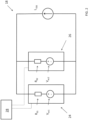
- Fig. 2 schematically illustrates an embodiment of the electric energy storage system 18.
- the Fig. 2 electric energy storage system 18 may be used for powering a vehicle, such as the Fig. 1 vehicle 10.
- embodiments of the electric energy storage system 18 according to the present disclosure may be used for any application delivering and/or requiring electric power.
- embodiments of the electric energy storage system 18 may be used in a stationary energy storage application (not shown) as well like in smart grid, back-up power, charger support or the like.
- the electric energy storage system 18 comprises at least two battery units 24, 26 electrically connected in parallel to each other.
- the Fig. 2 embodiment of the electric energy storage system 18 contains only two battery units, it is envisage that other embodiments may comprise more than two battery units (not shown).
- a set of battery unit specific battery values is associated with each one of the battery units 24, 26.
- Such battery unit specific battery values include at least an internal ohmic resistance value R 01 , R 02 indicative of the internal ohmic resistance of the battery unit 24, 26 and an open circuit voltage value V 0c1 , V oc2 indicative of the open circuit voltage of the battery unit 24, 26.
- R 0i an internal ohmic resistance value for a battery unit i
- V oci an open circuit voltage value for a battery unit i
- the battery units according to the present disclosure may be same or different, and may for instance be of lithium-ion or sodium-ion type.
- a sodium-ion battery typically includes any type of sodium iron battery or sodium ferrite battery.
- Fig. 2 further illustrates that the electric energy storage system 18 may further comprise a battery management system 28.
- the battery management system 28 may be adapted to receive information from the electric energy storage system 18.
- the battery management system 28 may be adapted to receive information indicative of the one or more parameters indicating the status of each battery unit 24, 26, for instance at a certain time instant.
- embodiments of the electric energy storage system 18 may comprise individual battery management units (not shown in Fig. 2 ) for each battery unit 24, 26.
- an individual battery management unit may receive and process one or more parameters indicating the status of each battery unit 24, 26 and forward information to an electric energy storage system corresponding to e.g. an electric energy storage system control unit (not shown).
- the system may be adapted to carry out one or more embodiments of the methods according to any one of the aspects according to the present disclosure.
- Example embodiments are presented hereinbelow. In order to keep the description brief, the below description generally uses a method as an example for presenting various features of the present disclosure. However, it should be noted that the description of the method should be equally applicable to the battery management system 28 and vice versa.
- a first aspect of the present disclosure relates to a method for predicting an electric load L i imparted on each battery unit i in an electric energy storage system 18 comprising at least two battery units 24, 26 electrically connected in parallel to each other.
- the method comprises:
- the imparted load may comprise two addends A i1 , A i2 , viz a first A i1 and a second addend A i2 .
- the first addend A i1 may be indicative of differences in the internal ohmic resistance values amongst the battery units of the electric energy storage system.
- the differences in the internal ohmic resistance values may also be referred to as a resistance imbalance between the battery units 24, 26 of the electric energy storage system 18.
- the second addend A i2 may be indicative of differences in the open circuit voltage values amongst the battery units of the electric energy storage system.
- the first addend A i1 for a certain battery unit of the electric energy storage system may comprise a first addend factor multiplied by the electric load level L ess .
- the first addend factor comprises a numerator and a denominator ⁇ in accordance with the following:
- the first addend A 11 for the first battery unit 1 in the set may be formulated in accordance with the following:
- the second addend A i2 for a certain battery unit is proportional to the sum of a set of summands.
- the number of the summands corresponds to the number of battery units minus one, and each summand is associated to a specific battery unit being different from the certain battery unit and the summand being calculated in accordance with the following:
- index i indicates the certain battery unit and index k indicates the specific battery unit.
- each one of the summand may be divided by a denominator ⁇ , which denominator has been presented hereinabove.
- the second addend A 12 for the first battery unit 1 in the set may be formulated in accordance with the following:
- the loads L i , L ESS have been expressed as electric currents I i , I ESS .
- the loads L i , L ESS may be expressed as electric powers P i , P ESS .
- the load L i of a battery unit i may also be determined taking one or more additional parameters into account.
- additional parameter(s) may be related to each individual battery unit 24, 26 of the electric energy storage system 18 and/or to the electric interaction, preferably the electrical dynamic interaction, between the battery units 24, 26 of the electric energy storage system 18.
- the electrical connection resistance between battery units may be considered.
- the battery parameter set further comprises one, more or all of the following values for each battery unit 24, 26 in the electric energy storage system: a state-of-charge value SoC i indicative of the state-of-charge of the battery unit, a state-of-health value SoH i indicative of the state-of-health of the battery unit and an internal impedance value Z i indicative of the internal impedance of the battery unit.
- the method according to the first aspect of the present disclosure comprises predicting the imparted load on each battery unit 24, 26 in the electric energy storage system by employing a multi-battery model that takes into account the electric interaction, preferably the electrical dynamic interaction, between the battery units 24, 26 of the electric energy storage system 18.
- the electric energy storage system has a set of connective resistances R ci-1,i comprising a connective resistance between each adjacent pair of battery units in the electric energy storage system 18 and/or a connective resistance R ci between each battery unit and a reference point in the electric energy storage system 18.
- a connective resistance between each adjacent pair of battery units in the electric energy storage system 18 may be related to a so called daisy-chain configuration of the battery units.
- a connective resistance R ci between each battery unit and a reference point in the electric energy storage system 18 may generally be attributed to a so called star configuration of the battery units.
- the method according to the present disclosure is intended to cover each one or a combination of the daisy-chain and star configurations.
- the method further comprises also using the set of connective resistances R ci-1,i for determining an imparted load on each battery unit in the electric energy storage system.
- Each individual battery unit (i) may be modelled by equivalent circuit as shown in Fig. 3 may be regarded as having the following main elements:
- a 1 i t 1 ⁇ 1 i t
- U heat,i ( t ) I i ⁇ ( V oci - V i ) is the total heat generation in the battery
- T fi is the coolant temperature
- a ti and b ti are thermal constants that depend on heat capacity, thermal resistance, and heat transfer properties of coolant.
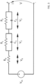
- FIG. 4 An example of a parallel configuration of battery modules is presented in Fig. 4 .
- Fig. 4 illustrates that the electric energy storage system 18 disclosed therein comprises a set of connective resistances R ci-1,i comprising a connective resistance between each adjacent pair of battery units i-1,i in the electric energy storage system.
- the system matrix A I , the input matrix B I , the output matrix C I and the feedthrough matrix D I are nonlinear functions of system parameters ( R 0 i , R 1 i , R 2 i , C 1 i , C 2 i , Q i ,R ci -1 ,i , R ci ) and system electro-thermal and ageing states ( SoC i , T i , SoQ i ,SoR i ). Note that as compared to a single battery model, the open circuit voltage of each battery unit has been included as an additional state in order to derive a complete model for parallel multi-battery systems.
- the state-space model is a vector-valued linear differential equation in the time domain (by virtue of the time derivative ⁇ ) and such a differential equation may be solved using a standard method, such as the backward Euler method.
- ⁇ is a parameter of the accumulated resistance.
- ⁇ V oc 1 ⁇ T 1 and ⁇ V oc 2 ⁇ T 2 are the jacobians of the open circuit voltage V OCi of a battery unit with respect to the battery unit's temperature T i .
- Such jacobians are treated as parameters in the model and may for instance be stored in look-up tables in a computer memory.
- the load - here exemplified as the electric current - imparted on each one of the battery units may be determined using internal ohmic resistance values R 0i and open circuit voltage value V oci for each battery unit as well as the connective resistances relating to the position of each battery in the electric energy storage system 18.
- the connective resistance R c12 between the battery units - generally used for a daisy-chain configuration of battery units - has been employed.
- the above equations could easily be modified so as to also, or instead, include a connective resistance R c1 , R c2 between each battery unit and a reference point in the electric energy storage system 18 - which connective resistance generally is employed for a so called star configuration of battery units.
- a connective resistance R c01 between the first battery unit and the load L ESS (exemplified as I ESS above) but such a connective resistance R c01 may be omitted in the above equations. This is since the connective resistance R c01 will form a common resistance in the path of each one of the battery units and may thus not have any influence of the load distribution among the battery units.
- Eq. 12 represents a linear differential equation in the time domain (by virtue of the time derivative ⁇ ) and such a differential equation may be solved using standard approaches, such as the backward Euler method. Such standard approaches may be used for any number of battery units in the electric energy storage system 18.
- the thus determined electric loads L i may be used for a plurality of purposes.
- the second aspect of the present disclosure relates to one such use.
- the second aspect of the present disclosure relates to a method for evaluating the impact that an electric load level will have on an electric energy storage system 18 comprising at least two battery units 24, 26 electrically connected in parallel to each other.
- the method comprises:
- the method according to the second aspect of the present disclosure determines a state-of-power value SOPi, SOPi(k) for each battery unit 24, 26 in the electric energy storage system 18. Such a determination may be performed in a plurality of different ways.
- a supplier of battery unit may provide information indicative of the battery unit state-of-power value SOP i .
- the battery unit state-of-power value SOP i may be determined before adding the battery unit to an electric energy storage system 18, for instance using a test procedure or the like.
- the state-of-power value SOP i for each battery unit 24, 26 may be determined using individual battery management units (not shown in Fig. 2 ) as have been discussed above. Alternatively, the state-of-power value SOP i for each battery unit 24, 26 may be determined using a central system, such as the battery management system 28 in Fig. 2 .
- the battery unit state-of-power value SOP i may be set to be constant over a certain time period.
- the battery unit state-of-power value SOP i may be set to be time dependent and may thus be denoted as SOP i (k) for instance.
- the battery unit state-of-power value SOP i may be determined using a single battery model as will be discussed hereinbelow.
- the battery unit state-of-power value SOP i may simply be equated to the maximum current that can be imparted on the battery unit.
- a single battery model may comprise the previously mentioned open circuit voltage V oci , the previously mentioned internal resistance R 0i , a minimum voltage limit V i min and a maximum voltage limit V i max .
- the above parameters may be static value or values that are assumed to be constant for a certain time range, such as the predetermined future time range discussed above.
- a single battery model also may comprise additional terms, e.g. one or more RC pairs as shown in Fig. 3 for modelling dynamic concentration and activation polarizations inside battery cells as has also been mentioned above.
- V oci the open circuit voltage V oci can be modelled so as to be dependent on the state of charge SoC i of the battery unit.
- the state of charge SoC i may be a time dependent parameter.
- the internal resistance R 0i may also be dependent on whether electric current is charged to or discharged from the battery unit.
- the battery unit may comprise a charging internal resistance R 0i,charge , as well as a discharging internal resistance R 0i,discharge .
- a charging internal resistance R 0i,charge as well as a discharging internal resistance R 0i,discharge .
- the maximum current for a battery unit may be determined in a plurality of different ways. Purely by way of example, the maximum current may be determined in a test environment.
- the maximum current may be determined using an optimization procedure taking e.g. the electro-thermal dynamics, the state of charge limits, and voltage limits of the battery unit into account.
- the state-of-power may be determined by solving the maximization problem in Eq. 19 hereinbelow using the boundary conditions (i.e., electro-thermal constraints) as presented in Eq. 20 to Eq. 27 for a predetermined future time range ⁇ t.
- the current limits i.e. I i,minAbs and I i,maxAbs , respectively may relate to absolute maximum current safety limits according to e.g. manufacturer datasheet which should not be exceeded in order to ensure that hazardous events are avoided.
- the method according to the second aspect of the present disclosure determines whether or not the battery load L i exceeds the state-of-power value SOP i , SOP i (k) for each battery unit 24, 26.
- the battery load L i and the state-of-power value SOP i , SOP i (k) are preferably expressed as the same entity, e.g. in terms of electric power or electric current.
- the predicted battery current may be expressed as I i and the state-of-power value may be expressed as I i max and the above-mentioned determination - viz whether or not the battery load Li exceeds the state-of-power value SOPi, SOPi(k) for each battery unit 24, 26 - may be expressed a determining whether or not the below condition is met for the battery unit: I i ⁇ I i max
- a battery unit may be associated with two state-of-power values: a charge state-of-power value SOP i,charge and a discharge state-of-power value SOP i,discharge .
- SOP i charge state-of-power value
- SOP i (k) discharge state-of-power value
- the method according to the second aspect of the present disclosure may for instance be used in a method according to a third aspect of the present disclosure.
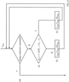
- An embodiment of the method according to the third aspect of the present disclosure is presented hereinbelow with reference to Fig. 5 .
- Fig. 5 illustrates a method for determining an electric load L ESS to be imparted on an electric energy storage system 18 comprising at least two battery units 24, 26 electrically connected in parallel to each other.
- the method may for instance use a starting value for the electric load L ESS .
- a starting value may be set to zero.
- the starting value L' ESS for the electric load L ESS may be selected using e.g. an heuristic approach.
- a starting value L' ESS may be set as the sum of the state-of-power value SOP i , SOP i (k) for each battery unit 24, 26 in the electric energy storage system 18.
- the method comprises employing a correction process comprising the following correction steps: S1 Evaluating the impact that an electric load level L ESS will have on the electric energy storage system 18 using the method according to the second aspect of the present disclosure.
- the method according to the third aspect of the present disclosure obtains information whether or not the battery load L i - which is the predicted battery load L i for the electric load level L ESS - exceeds the state-of-power value SOP i , SOP i (k) for each battery unit 24, 26.
- SOP i (k) for at least one of the battery units 24, 26, reducing the electric load level L ESS .
- the electric load level L ESS may be reduced by a predetermined value ⁇ L ESS .
- the predetermined value ⁇ L ESS may for example be determined based on the level of violation or offset between L i and SOP i .
- the electric load level L ESS may be reduced by a predetermined value ⁇ L ESS .
- the method as illustrated in Fig. 5 corrects the electric load L ESS in dependence on whether or not any state-of-power value SOP i , SOP i (k) is exceeded.
- the correction procedure in Fig. 5 may be performed a plurality of times.
- the correction process according to the third aspect of the present disclosure and exemplified in Fig. 5 may be an iterative process that repeats the correction steps above until a stopping criterion has been reached.
- Fig. 6 illustrating an embodiment of the method according to the third aspect of the present disclosure which comprises a step S4 that evaluates whether or not a stopping criterion has been reached.
- the correction process as outlined hereinabove with reference to steps S1 - S3, see also Fig. 6 , is terminated.
- the stopping criterion may be formulated in a plurality of different ways.
- the stopping criterion may comprise that a smallest battery offset value, being the difference between the battery load and the state-of-power value for a battery unit, among the battery units 24 26, is within a predetermined threshold range, preferably the predetermined threshold range is zero.
- the predetermined threshold range as discussed hereinabove may be regarded as a tolerance for the equality expressed in Eq. 30 such that the stopping criterion need not require that a battery load L i must equal the state-of-power value SOP i , SOP i (k).
- the above-mentioned predetermined threshold range may be expressed as a fraction of the state-of-power value SOP i , SOP i (k) for the battery unit concerned. Consequently, the stopping criterion may be formulated as
- ⁇ may be selected to be in the range of 0.001 - 0.05, preferably within the range of 0.001 - 0.01.
- a fourth aspect of the present disclosure relates to a method for determining an electric load L ESS to be imparted on an electric energy storage system 18 comprising at least two battery units 24, 26 electrically connected in parallel to each other.
- the method according to the fourth aspect of the present disclosure employs the method for evaluating the impact that an electric load level L ESS will have on an electric energy storage system according to the second aspect of the present disclosure and comprises determining the largest electric load L ESS that can be imparted on an electric energy storage system 18 without the battery load exceeding the state-of-power value SOP i , SOP i (k) for any battery unit in the electric energy storage system.
- the optimization problem in Eq. 31 may be adapted to a charging condition or a discharging condition.
- Each one of the method embodiments presented hereinabove comprises predicting an imparted load on each battery unit 24, 26 in an electric energy storage system 18.
- a fifth aspect of the present disclosure relates to a method for determining an electric load L ESS to be imparted on an electric energy storage system 18 comprising at least two battery units 24, 26 electrically connected in parallel to each other.
- the battery parameter set comprising at least the following values for each battery unit in the electric energy storage system: an internal ohmic resistance value R 0i indicative of the internal ohmic resistance of the battery unit and an open circuit voltage value V oci indicative of the open circuit voltage of the battery unit.
- the determination of the state-of-power value SOP i , SOP i (k) has also been presented hereinabove and is thus not repeated here.
- the battery unit measure BUM i may be determined in accordance with the following: BUM i ⁇ R 0 i ⁇ SOP i + V oci
- Eq. 49 may be formulated in accordance with the following: BUM i ⁇ R 0 i ⁇ I i , charging max + V oci
- the method according to the fifth aspect of the present disclosure further comprises: among the battery units i in the electric energy storage system 18, determining the smallest magnitude of the battery unit measure BUM min in order to arrive at an electric load measure indicative of the electric load to be imparted on an electric energy storage system.
- BUM min min i ⁇ 1 , ⁇ , n BUM i
- the smallest magnitude of the battery unit measure BUM min may be used directly in a procedure for determining an electric load L ESS to be imparted on an electric energy storage system 18 comprising at least two battery units 24, 26.
- embodiments of the fifth aspect of the present disclosure may use the above procedure for identifying the battery unit i being associated with the smallest magnitude of the battery unit measure BUM min and on the basis thereof determine the electric load L ESS .
- the method according to the fifth aspect of the present disclosure may further comprise multiplying the smallest unit magnitude measure by the sum of the inverse of the internal ohmic resistance value R 0i for each battery unit i in the electric energy storage system 18. Moreover, the method according to the fifth aspect of the present disclosure may further comprise subtracting the ratio between the open circuit voltage V oci and the internal ohmic resistance R 0i for each battery unit i in the electric energy storage system 18 from the electric load measure BUM i .
- Embodiments of the method of the fifth aspect of the present disclosure may comprise only one of the above modifications - viz multiplying the smallest unit magnitude measure by the sum of the inverse of the internal ohmic resistance value R 0i for each battery unit i as well as subtracting the ratio between the open circuit voltage V oci and the internal ohmic resistance R 0i for each battery unit i - to the electric load measure BUM i .
- the current I is used as an example of the state-of-power value SOP i , SOP i (k) for a charging condition and a discharging condition, respectively.
- a sixth aspect of the present disclosure relates to a method for controlling the loading of an electric energy storage system 18 comprising at least two battery units 24 ,26 electrically connected in parallel to each other.
- the method comprises determining the electric load to be imparted on an electric energy storage system using the method according to any one of the third to fifth aspects of the present disclosure, and imparting the thus determined electric load L ESS on the energy storage system 18, e.g. by charging or discharging the energy storage system 18.
- the state-of-power value SOP i , SOP i (k) may be indicative of the maximum amount of electric current I, alternatively electric power P, that the battery unit i can deliver or receive at a constant load level during the predetermined future time range without violating electro-thermal limits of said battery unit i .
- the electric load L ESS may be indicative of electric current I ESS , alternatively electric power P ESS .
Landscapes
- Engineering & Computer Science (AREA)
- Power Engineering (AREA)
- Life Sciences & Earth Sciences (AREA)
- Sustainable Development (AREA)
- Sustainable Energy (AREA)
- Transportation (AREA)
- Mechanical Engineering (AREA)
- Physics & Mathematics (AREA)
- General Physics & Mathematics (AREA)
- Manufacturing & Machinery (AREA)
- Chemical & Material Sciences (AREA)
- Chemical Kinetics & Catalysis (AREA)
- Electrochemistry (AREA)
- General Chemical & Material Sciences (AREA)
- Microelectronics & Electronic Packaging (AREA)
- Secondary Cells (AREA)
- Charge And Discharge Circuits For Batteries Or The Like (AREA)
- Electric Propulsion And Braking For Vehicles (AREA)
Description
- The present disclosure relates to a method for determining an electric load to be imparted on an electric energy storage system. Furthermore, the present disclosure relates to a method for controlling the loading of an electric energy storage system. The present disclosure also relates to a computer program as well as to a computer readable medium. Further, the present disclosure relates to a battery management system for an electric energy storage system.
- Energy storage systems are frequently used in a wide variety of applications and fields of technology. In the automotive industry, energy storage systems may be used for propulsion of a vehicle as well as for providing electrical energy to various systems of a vehicle. As another non-limiting example, energy storage systems may be used in stationary energy storage applications, for instance in so called smart grid and power back-up applications.
- In order to increase the power capability of the energy storage system, a solution can be provided where two or more battery modules/battery packs of the energy storage system are connected in parallel to each other. Hereby, the individual battery modules can be easily connected to, or disconnected from, each other. Also, an increased total power capability is provided in comparison to using only a single battery module/battery pack.
- However, a problem with energy storage systems having battery modules connected in parallel is that the battery modules need to be in approximately the same physical state for optimal energy usage. It is however a common scenario that the battery modules/battery packs are not in the same physical state. For example, if the parallel connected battery modules are differently aged, i.e. one of the battery modules has been recently replaced by a new and unused battery module, there will most likely be a difference in power capability between the differently aged battery modules. For instance, the older and weaker battery module may have a complicated dynamic interaction with the new and more powerful battery module and may thus pull down the total available power of this joint system as compared to their individual sum. In short, the maximum available power of the energy storage system will be limited by the weakest link in the system, i.e. the oldest battery module.
- Also, care should be taken when mixing battery modules/packs of different generation/types of in an energy storage system, since their characteristics, such as internal resistance, open-circuit-voltage (OCV), capacity, etcetera, may be significantly different from each other. Another example is that if one of the battery modules has a higher temperature than the other battery modules of the same energy storage system, the resistance of the battery module having elevated temperature will most likely be lower than the resistance of the battery modules having lower temperature. In such a situation, there is a risk that the warmer battery module will receive a charge current exceeding its threshold.
- Another problem with energy storage systems having parallel connected battery modules is that different battery packs may be placed in different locations of the vehicle, and may thus require high-voltage cables of different lengths, thereby introducing large differences in resistances.
- A typical approach to solve the above-mentioned problem is disclosed in
EP 3 011 655EP 3 011 655 - According to its abstract,
US 2018/134160 A1 relates to a traction energy storage system including multiple electrical energy stores and a system controller. Each of the energy stores includes one or more cell modules electrically connected via busbars, an energy store high-voltage interface connectable to the busbars and an energy store controller controlling the cell modules. Each of the cell modules comprises multiple storage cells and a cell module controller. Each of the cell module controllers is configured to output measured values relating to the storage cells in the respective cell module to the energy store controller. Each of the energy store controllers is configured to take the measured values obtained as a basis for generating signals having electrical characteristic quantities of the respective energy store and at least one limit value for a current through the energy store high-voltage interface of the respective energy store. - According to its abstract,
US 2014/372053 A1 relates to method for a battery pack controller of an electrified vehicle, the battery pack controller including one or more processors, includes identifying N battery cells of a battery pack that includes M battery cells, the N battery cells being weakest battery cells of the battery pack, wherein N is an integer greater than zero and less than M. The method includes determining one or more first parameters for each of the N battery cells, each of the one or more first parameters indicating a parameter for a specific battery cell. The method includes estimating one or more second parameters for the battery pack based on the one or more first parameters for each of the N battery cells, each of the one or more second parameters indicating a parameter for the battery pack. The method also includes outputting the one or more second parameters for the battery pack. - There is hence a need for improved controlling of charge and discharge capability for energy storage systems having battery units connected in parallel.
- In view of the above, an object of a first aspect of the present disclosure is to provide a method implying an appropriate use of an electric energy storage system.
- As such, a first aspect of the present disclosure relates to a method according to
claim 1. - Thus, by virtue of the above method, it is possible to predict the influence that a total electric energy storage system load may have on each battery unit in an electric energy storage system. Moreover, since the above method takes at least each battery unit's internal ohmic resistance and open circuit voltage into account, such influence may be determined with an appropriate level of accuracy.
- Information indicative of the imparted load on each battery unit in the electric energy storage system may be used for a plurality of purposes as will be elaborated on hereinbelow.
- Optionally, the method according to the first aspect of the present disclosure comprises predicting the imparted load on each battery unit in the electric energy storage system by employing a multi-battery model that takes into account the electric interaction, preferably the electrical dynamic interaction, between the battery units of the electric energy storage system.
- Taking the electric interaction into account may further enhance the accuracy when predicting the loads imparted on the battery units.
- Optionally, the imparted load comprises two addends: a first addend indicative of differences in the internal ohmic resistance values amongst the battery units of the electric energy storage system and a second addend indicative of differences in the open circuit voltage values amongst the battery units of the electric energy storage system.
- Optionally, the first addend for a certain battery unit of the electric energy storage system comprises a first addend factor multiplied by the electric load level, the first addend factor comprising a numerator and a denominator in accordance with the following:
- for the certain battery unit, the numerator comprising the product of the internal ohmic resistance values of every battery unit in the electric energy storage system except for the certain battery unit, and
- the denominator comprises the sum of a set of products, the number of the products corresponding to the number of battery units in the electric energy storage system and each product being assigned to an individual battery unit of the electric energy storage system, wherein a product for a certain battery unit is obtained by multiplying internal ohmic resistance values of all battery units in the electric energy storage system except for the individual battery unit.
- Optionally, the second addend for a certain battery unit is proportional to the sum of a set of summands, the number of the summands corresponding to the number of battery units minus one, and each summand is associated to a specific battery unit being different from the certain battery unit and the summand being calculated in accordance with the following:
- for each battery unit in the electric energy storage system which is not the certain battery unit: calculating the difference in the open circuit voltage values between the battery unit and the certain battery unit and multiplying that difference by the product of the internal ohmic resistance value of each one of the battery units in the electric energy storage system, except for the certain battery unit and the specific battery unit and adding that value to the summand.
- Optionally, each one of the summand is divided by a denominator, the denominator comprising the sum of a set of products, the number of the products corresponding to the number of battery units in the electric energy storage system and each product being assigned to an individual battery unit of the electric energy storage system, wherein a product for a certain battery unit is obtained by multiplying internal ohmic resistance values of all battery units in the electric energy storage system except for the individual battery unit.
- Optionally, the battery parameter set further comprises one, more or all of the following values for each battery unit in the electric energy storage system: a state-of-charge value indicative of the state-of-charge of the battery unit, a state-of-health value indicative of the state-of-health of the battery unit and an internal impedance value indicative of the internal impedance of the battery unit.
- Optionally, the electric energy storage system has a set of connective resistances comprising a connective resistance between each adjacent pair of battery units in the electric energy storage system and/or a connective resistance between each battery unit and a reference point in the electric energy storage system. The method further comprises also using the set of connective resistances for determining an imparted load on each battery unit in the electric energy storage system.
- The method of
claim 1 further comprises a method for evaluating the impact that an electric load level will have on an electric energy storage system comprising at least two battery units electrically connected in parallel to each other. The method comprises: - for each battery unit in the electric energy storage system, determining a state-of-power value, the state-of-power value being indicative of the maximum amount of electric load that the battery unit can deliver or receive at a constant load level during a predetermined future time range without violating electro-thermal limits of the battery unit,
- on the basis of the electric load level, predicting the electric load imparted on each battery unit in an electric energy storage system according to the method of the first aspect of the present disclosure, and
- for each battery unit in the electric energy storage system, determining whether or not the battery load exceeds the state-of-power value.
- As has been intimated above, the first aspect
of the present disclosure relates to a method for determining an electric load to be imparted on an electric energy storage system comprising at least two battery units electrically connected in parallel to each other. The method comprises employing a correction process comprising the following correction steps: - evaluating the impact that an electric load level will have on the electric energy storage system using the method according to the second aspect of the present disclosure,
- in response to the determination that the battery load exceeds the state-of-power value for at least one of the battery units, reducing the electric load level, and
- in response to the determination that the battery load is lower than the state-of-power value for each one of the battery units, increasing the electric load level,
- The method of the first aspect of the present disclosure implies that a suitable load level, preferably a load level with a maximum load amount, may be determined for the electric energy storage system without necessarily jeopardizing the health as well as the safety of any one of the battery units.
- Optionally, the correction process is an iterative process that repeats the correction steps above until a stopping criterion has been reached.
- Optionally, the stopping criterion comprises that a smallest battery offset value, being the difference between the battery load and the state-of-power value for a battery unit, among the battery units, is within a predetermined threshold range, preferably the predetermined threshold range is zero.
- A second aspect of the present disclosure relates to a method for controlling the loading of an electric energy storage system comprising at least two battery units electrically connected in parallel to each other, the method comprising determining the electric load to be imparted on an electric energy storage system using the method according to the first aspect of the present disclosure, and imparting the thus determined electric load on the energy storage system.
- Optionally, the state-of-power value is indicative of the maximum amount of electric current, alternatively electric power, that the battery unit can deliver or receive at a constant load level during the predetermined future time range without violating electro-thermal limits of said battery unit.
- Optionally, the electric load is indicative of electric current, alternatively electric power.
- A third aspect of the present disclosure relates to a computer program comprising program code means for performing the steps of any one of first to sixth aspects of the present disclosure when the program is run on a computer.
- An fourth aspect of the present disclosure relates to a computer readable medium carrying a computer program comprising program means for performing the steps of any one of first to sixth aspects of the present disclosure when the program means is run on a computer.
- An fifth aspect of the present disclosure relates to a battery management system for an electric energy storage system comprising at least two battery units electrically connected in parallel to each other, the battery management system being adapted to predict an electric load imparted on each battery unit in the electric energy storage system by:
- establishing a battery parameter set, the battery parameter set comprising at least the following values for each battery unit in the electric energy storage system: an internal ohmic resistance value indicative of the internal ohmic resistance of the battery unit and an open circuit voltage value indicative of the open circuit voltage of the battery unit,
- using an electric load level indicative of a total electric energy storage system load, and
- using the electric load level and the battery parameter set for predicting the imparted load on each battery unit in the electric energy storage system.
- Purely by way of example, the battery management system may be configured for determining an electric load to be imparted on an electric energy storage system according to the first aspect of the present disclosure and/or for controlling the loading of an electric energy storage system according to the second aspect of the present disclosure.
- The above, as well as additional objects, features and advantages of the present disclosure, will be better understood through the following illustrative and non-limiting detailed description of exemplary embodiments of the present disclosure, wherein:
-
Fig. 1 schematically illustrates a hybrid vehicle in the form of a bus, in which the present disclosure can be used, -
Fig. 2 schematically illustrates an embodiment of an electric energy storage system, and -
Fig. 3 schematically illustrates a single battery model, -
Fig. 4 schematically illustrates a multi-battery model, -
Fig. 5 illustrates a flowchart for an embodiment of a method according to a third aspect of the present disclosure, and -
Fig. 6 illustrates a flowchart for another embodiment of a method according to a third aspect of the present disclosure. - With reference to the appended drawings, below follows a more detailed description of embodiments of the disclosure cited as examples.
- The present disclosure will now be described more fully hereinafter with reference to the accompanying drawings, in which exemplary embodiments of the present disclosure are shown. The disclosure may, however, be embodied in many different forms and should not be construed as limited to the embodiments set forth herein; rather, these embodiments are provided for thoroughness and completeness. The skilled person will recognize that many changes and modifications may be made within the scope of the appended claims.
- Similar reference characters refer to similar elements throughout the description.
-
Fig. 1 illustrates a simplified perspective view of a vehicle in the form of abus 10 according to an embodiment of the present disclosure. In fact, theFig. 1 embodiment of thevehicle 10 is of the plug-in hybrid type which is equipped with aninternal combustion engine 12 and anelectric machine 14 which are connected to each other via a clutch 16 and wherein both theinternal combustion engine 12 and theelectrical machine 14 can be used to drive thebus 10. It is also contemplated that thevehicle 10 may be an electrical vehicle not comprising an internal combustion engine for the propulsion of the vehicle. Even though the present disclosure is described with reference to a vehicle in the form of a bus, it can be used for virtually any type of system for storing electric energy.Fig. 1 further illustrates that thevehicle 1 comprises an electricenergy storage system 18 which for instance may be adapted to power theelectrical machine 14 and/or other electrical components (not shown) of thevehicle 10. - Purely by way of example, and as indicated in
Fig. 1 , the electricenergy storage system 18 may be charged via anoverhead wire 20 and apantograph 22. However, it is also contemplated that the electricenergy storage system 18 may be charged using other means (not shown inFig. 1 ). - As may be realized from the above, the electric
energy storage system 18 may be charged with electric power and/or electric power may be discharged from the electricenergy storage system 18. -
Fig. 2 schematically illustrates an embodiment of the electricenergy storage system 18. Purely by way of example, theFig. 2 electricenergy storage system 18 may be used for powering a vehicle, such as theFig. 1 vehicle 10. However, embodiments of the electricenergy storage system 18 according to the present disclosure may be used for any application delivering and/or requiring electric power. Purely by way of example, embodiments of the electricenergy storage system 18 may be used in a stationary energy storage application (not shown) as well like in smart grid, back-up power, charger support or the like. - As may be gleaned from
Fig. 2 , the electricenergy storage system 18 comprises at least twobattery units Fig. 2 embodiment of the electricenergy storage system 18 contains only two battery units, it is envisage that other embodiments may comprise more than two battery units (not shown). - Moreover, as indicated in
Fig. 2 , a set of battery unit specific battery values is associated with each one of thebattery units battery unit battery unit - The battery units according to the present disclosure may be same or different, and may for instance be of lithium-ion or sodium-ion type. A sodium-ion battery typically includes any type of sodium iron battery or sodium ferrite battery.
-
Fig. 2 further illustrates that the electricenergy storage system 18 may further comprise abattery management system 28. Purely by way of example, and as exemplified inFig. 2 , thebattery management system 28 may be adapted to receive information from the electricenergy storage system 18. Purely by way of example, thebattery management system 28 may be adapted to receive information indicative of the one or more parameters indicating the status of eachbattery unit - Instead of, or in addition to, the above-mentioned
battery management system 28, embodiments of the electricenergy storage system 18 may comprise individual battery management units (not shown inFig. 2 ) for eachbattery unit battery unit - Irrespective of the configuration of the
battery management system 28, the system may be adapted to carry out one or more embodiments of the methods according to any one of the aspects according to the present disclosure. Example embodiments are presented hereinbelow. In order to keep the description brief, the below description generally uses a method as an example for presenting various features of the present disclosure. However, it should be noted that the description of the method should be equally applicable to thebattery management system 28 and vice versa. - As such, a first aspect of the present disclosure relates to a method for predicting an electric load Li imparted on each battery unit i in an electric
energy storage system 18 comprising at least twobattery units - establishing a battery parameter set, the battery parameter set comprising at least the following values for each battery unit in the electric energy storage system: an internal ohmic resistance value R0i indicative of the internal ohmic resistance of the battery unit and an open circuit voltage value Voci indicative of the open circuit voltage of the battery unit,
- using an electric load level LESS indicative of a total electric energy storage system load, and
- using the electric load level LESS and the battery parameter set for predicting the imparted load Li on each battery unit in the electric energy storage system.
- Purely by way of example, the imparted load may comprise two addends Ai1, Ai2, viz a first Ai1 and a second addend Ai2. The first addend Ai1 may be indicative of differences in the internal ohmic resistance values amongst the battery units of the electric energy storage system. The differences in the internal ohmic resistance values may also be referred to as a resistance imbalance between the
battery units energy storage system 18. Moreover, the second addend Ai2 may be indicative of differences in the open circuit voltage values amongst the battery units of the electric energy storage system. - As a non-limiting example, the first addend Ai1 for a certain battery unit of the electric energy storage system may comprise a first addend factor multiplied by the electric load level Less. The first addend factor comprises a numerator and a denominator θ in accordance with the following:
- for the certain battery unit, the numerator comprising the product of the internal ohmic resistance values of every battery unit in the electric energy storage system except for the certain battery unit, and
- the denominator θ comprises the sum of a set of products, the number of the products corresponding to the number of battery units in the electric energy storage system and each product being assigned to an individual battery unit of the electric energy storage system, wherein a product for a certain battery unit is obtained by multiplying internal ohmic resistance values of all battery units in the electric energy storage system except for the individual battery unit.
- For a set of
n battery units 1, ... , n in a electricenergy storage system 18, the first addend Ai1 for a battery unit i in the set may be formulated in accordance with the following:

- For a set of n battery units only containing three battery units, using Eq. 1 and Eq. 2, the first addend A11 for the
first battery unit 1 in the set may be formulated in accordance with the following:

- Moreover, the second addend Ai2 for a certain battery unit is proportional to the sum of a set of summands. The number of the summands corresponds to the number of battery units minus one, and each summand is associated to a specific battery unit being different from the certain battery unit and the summand being calculated in accordance with the following:
- for each battery unit in the electric energy storage system which is not the certain battery unit: calculating the difference in the open circuit voltage values between the battery unit and the certain battery unit and multiplying that difference by the product of the internal ohmic resistance value of each one of the battery units in the electric energy storage system, except for the certain battery unit and the specific battery unit and adding that value to the summand.
- The above approach is presented hereinbelow wherein index i indicates the certain battery unit and index k indicates the specific battery unit.

- Moreover, each one of the summand may be divided by a denominator θ, which denominator has been presented hereinabove. As such, the second addend Ai2 may be formulated in accordance with the following:


- For a set of n battery units only containing three battery units, using Eq. 6 and Eq. 7, the second addend A12 for the
first battery unit 1 in the set may be formulated in accordance with the following:

- Combining Eq. 1, Eq. 6 and Eq. 7 results in the following expression for the load Li of a battery unit i:


- In the above examples, the loads Li, LESS have been expressed as electric currents Ii, IESS. However, it is also envisaged that the loads Li, LESS may be expressed as electric powers Pi, PESS.
- The load Li of a battery unit i may also be determined taking one or more additional parameters into account. Purely by way of example, such additional parameter(s) may be related to each
individual battery unit energy storage system 18 and/or to the electric interaction, preferably the electrical dynamic interaction, between thebattery units energy storage system 18. As another non-limiting example, the electrical connection resistance between battery units may be considered. - Purely by way of example, the battery parameter set further comprises one, more or all of the following values for each
battery unit - Instead of, or in addition to, the above parameters, the method according to the first aspect of the present disclosure comprises predicting the imparted load on each
battery unit battery units energy storage system 18. Purely by way of example, the electric energy storage system has a set of connective resistances Rci-1,i comprising a connective resistance between each adjacent pair of battery units in the electricenergy storage system 18 and/or a connective resistance Rci between each battery unit and a reference point in the electricenergy storage system 18. - Generally, a connective resistance between each adjacent pair of battery units in the electric
energy storage system 18 may be related to a so called daisy-chain configuration of the battery units. Moreover, a connective resistance Rci between each battery unit and a reference point in the electricenergy storage system 18 may generally be attributed to a so called star configuration of the battery units. The method according to the present disclosure is intended to cover each one or a combination of the daisy-chain and star configurations. - As a non-limiting example, the method further comprises also using the set of connective resistances Rci-1,i for determining an imparted load on each battery unit in the electric energy storage system.
- The above alternatives are presented using example embodiments hereinbelow.
- Each individual battery unit (i) may be modelled by equivalent circuit as shown in
Fig. 3 may be regarded as having the following main elements: - the previously mentioned internal ohmic resistance R 0i that may be regarded as a nonlinear function of state-of-charge SoCi and temperature Ti, of the battery unit i,
- a fast dynamic activation polarization modelled by RC pair R 1i and C 1i which are nonlinear functions of state-of-charge SoCi and temperature Ti, and input load Li, e.g. input current Ii,, of the battery unit i,
- a slow dynamic concentration polarization modelled by RC pair R 2i and C 2i which are nonlinear functions of state-of-charge SoCi and temperature Ti, and input current Ii, of the battery unit i,
- the previously mentioned open circuit voltage VOCi that may be regarded as a nonlinear function of state-of-charge SoCi and temperature Ti, of the battery unit i,
- The electro-thermal dynamics of any individual battery unit (i) within the electric
energy storage system 18 can be represented on the following standard continuous-time state-space form:




Voci (t) = focv (SoC(t)) gives open-circuit voltage as a function of battery SoC. - Note that


- An example of a parallel configuration of battery modules is presented in
Fig. 4 . -
Fig. 4 illustrates that the electricenergy storage system 18 disclosed therein comprises a set of connective resistances Rci-1,i comprising a connective resistance between each adjacent pair of battery units i-1,i in the electric energy storage system. Such a connection resistance may be formulated as:
- Following Kirchhoff's laws, constraints imposed by the parallel connections may be formulated as:


- Now mainly using single battery model for each battery unit and exploiting parallel connection constraints among them as given above, a complete state-space model of a parallel
multi-battery system 18 may be formulated in accordance with the following:

- In Eq. 12, x = [x 1 ··· xn ] T which is the full state vector of the complete electric
energy storage system 18 wherein xi = [V 1 i V 2 i VOCi SoCi Ti ] T is the state of each battery unit i. The output of the system is represented by y = [I 1 ··· In ] T where Ii is the output current of each battery unit i. The control input of the state-space model is given by u = [IESS U h,1 ··· U h,1] T wherein IESS is the total (e.g. total demanded) input current and Uh,l is the total heat generated inside a battery unit i. It should be noted that IESS may be regarded as an implementation of the total (e.g. total demanded) input load LESS. - The system matrix AI, the input matrix BI, the output matrix CI and the feedthrough matrix DI are nonlinear functions of system parameters (R 0 i, R 1 i, R 2 i, C 1 i, C 2 i, Qi,R ci-1 ,i, Rci ) and system electro-thermal and ageing states (SoCi, Ti, SoQi,SoRi ). Note that as compared to a single battery model, the open circuit voltage of each battery unit has been included as an additional state in order to derive a complete model for parallel multi-battery systems.
- As may be realized from Eq. 12 hereinabove, the state-space model is a vector-valued linear differential equation in the time domain (by virtue of the time derivative ẋ ) and such a differential equation may be solved using a standard method, such as the backward Euler method.
- In order to exemplify the above equations, the full matrices for n=2 are presented hereinbelow. The full state vector x for an electric
energy storage system 18 with two battery units is given by:


- The system matrix AI comprises submatrices in accordance with the following:


- As such, Ω is a parameter of the accumulated resistance. Note that
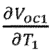

- Again with reference to Eq. 12, the input matrix BI may be formulated as:
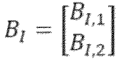

- The output matrix is given by:


- As may be gleaned from the above, various system parameters, including battery impedances, capacities, cable connection resistances, temperatures etcetera enter into this model through the above matrices. This enables prediction of load, e.g. power or current, split between batteries with an appropriately high accuracy under given operating conditions.
- It should also be noted that the above equations may be simplified by dropping all states related to internal polarizations and temperature from the above-mentioned model such that each element in the above-mentioned matrices AI, BI, CI and DI relating to internal polarizations and temperature is set to zero. Using such an approach for the matrices discussed hereinabove for the above example, viz a system with two battery units such that n=2, the following equations are obtained for the electric currents for each one of the battery units:


- As may be gleaned from the above, the load - here exemplified as the electric current - imparted on each one of the battery units may be determined using internal ohmic resistance values R0i and open circuit voltage value Voci for each battery unit as well as the connective resistances relating to the position of each battery in the electric
energy storage system 18. In the above equations, the connective resistance Rc12 between the battery units - generally used for a daisy-chain configuration of battery units - has been employed. However, the above equations could easily be modified so as to also, or instead, include a connective resistance Rc1, Rc2 between each battery unit and a reference point in the electric energy storage system 18 - which connective resistance generally is employed for a so called star configuration of battery units. For the sake of completeness, it should be noted that there may be a connective resistance Rc01 between the first battery unit and the load LESS (exemplified as IESS above) but such a connective resistance Rc01 may be omitted in the above equations. This is since the connective resistance Rc01 will form a common resistance in the path of each one of the battery units and may thus not have any influence of the load distribution among the battery units. - Moreover, the equation presented hereinabove using the internal ohmic resistance values R0i, the open circuit voltage value Voci and the connective resistances could easily be expanded to any number n of battery units.
- Furthermore, as has been intimated above, Eq. 12 represents a linear differential equation in the time domain (by virtue of the time derivative ẋ) and such a differential equation may be solved using standard approaches, such as the backward Euler method. Such standard approaches may be used for any number of battery units in the electric
energy storage system 18. - Irrespective of how the electric load Li - exemplified by Ii in the above presentation - imparted on each
battery unit energy storage system 18 is predicted, e.g. using Eq. 10 and Eq. 11 or Eq. 12, the thus determined electric loads Li may be used for a plurality of purposes. - The second aspect of the present disclosure relates to one such use.
- As such, the second aspect of the present disclosure relates to a method for evaluating the impact that an electric load level will have on an electric
energy storage system 18 comprising at least twobattery units - The method comprises:
- for each
battery unit energy storage system 18, determining a state-of-power value SOPi, SOPi(k), the state-of-power value being indicative of the maximum amount of electric load that the battery unit can deliver or receive at a constant load level during a predetermined future time range without violating electro-thermal limits of the battery unit, - on the basis of the electric load level LESS, predicting the electric load Li imparted on each battery unit i in an electric energy storage system according to the method of the first aspect of the present disclosure, e.g. using Eq. 10 and Eq. 11 or Eq. 12 hereinabove, and
- for each battery unit i in the electric energy storage system, determining whether or not the battery load exceeds the state-of-power value SOPi, SOPi(k).
- As may be realized from the above, the method according to the second aspect of the present disclosure determines a state-of-power value SOPi, SOPi(k) for each
battery unit energy storage system 18. Such a determination may be performed in a plurality of different ways. As a non-limiting example, a supplier of battery unit may provide information indicative of the battery unit state-of-power value SOPi. As another non-limiting example, the battery unit state-of-power value SOPi may be determined before adding the battery unit to an electricenergy storage system 18, for instance using a test procedure or the like. - With reference to
Fig. 2 , the state-of-power value SOPi for eachbattery unit Fig. 2 ) as have been discussed above. Alternatively, the state-of-power value SOPi for eachbattery unit battery management system 28 inFig. 2 . - Purely by way of example, the battery unit state-of-power value SOPi may be set to be constant over a certain time period. As another non-limiting example, the battery unit state-of-power value SOPi may be set to be time dependent and may thus be denoted as SOPi(k) for instance.
- As other non-limiting examples, the battery unit state-of-power value SOPi may be determined using a single battery model as will be discussed hereinbelow.
- As a first example, the battery unit state-of-power value SOPi may simply be equated to the maximum current that can be imparted on the battery unit. As such, the battery unit state-of-power value SOPi may be expressed in accordance with the following:

- It should be noted that the maximum current may be different depending on whether electric current is charged to or discharged from the battery unit. As such, a battery unit may be associated with two state-of-power values: a charge state-of-power value SOPi,charge and a discharge state-of-power value SOPi,discharge, in accordance with the following:

- As a non-limiting example, a single battery model may comprise the previously mentioned open circuit voltage Voci, the previously mentioned internal resistance R0i, a minimum voltage limit Vi min and a maximum voltage limit Vi max. Purely by way of example, the above parameters may be static value or values that are assumed to be constant for a certain time range, such as the predetermined future time range discussed above. It should be noted that a single battery model also may comprise additional terms, e.g. one or more RC pairs as shown in
Fig. 3 for modelling dynamic concentration and activation polarizations inside battery cells as has also been mentioned above. - As such, in a simplified form, the battery unit state-of-power value SOPi, defined in terms of electric power, may be determined in accordance with the following:

- Here, it should be noted that the open circuit voltage Voci can be modelled so as to be dependent on the state of charge SoCi of the battery unit. Moreover, the state of charge SoCi may be a time dependent parameter. As such, Eq. 16 can be formulated in accordance with the following:

- It should be noted that the internal resistance R0i may also be dependent on whether electric current is charged to or discharged from the battery unit. As such, the battery unit may comprise a charging internal resistance R0i,charge, as well as a discharging internal resistance R0i,discharge. As such, in analogy with Eq. 15, battery unit may be associated with two state-of-power values in accordance with the following:

- For the sake of completeness, it should be noted that the maximum current for a battery unit, be it a charging or a discharging current, may be determined in a plurality of different ways. Purely by way of example, the maximum current may be determined in a test environment.
- Optionally, as a general formulation, the maximum current may be determined using an optimization procedure taking e.g. the electro-thermal dynamics, the state of charge limits, and voltage limits of the battery unit into account.
- Purely by way of example, using an example in which the state-of-power SOPi is defined in terms of electric current, the state-of-power may be determined by solving the maximization problem in Eq. 19 hereinbelow using the boundary conditions (i.e., electro-thermal constraints) as presented in Eq. 20 to Eq. 27 for a predetermined future time range Δt.

Electrical dynamics: 
Thermal dynamics: 
Battery Voltage Output: 
Battery Temperature: 
State-Of-Charge Limits: 
Voltage Limits: 
Temperature Limits: 
Current Limits: 
- Here, it should be noted that the current limits, i.e. Ii,minAbs and Ii,maxAbs, respectively may relate to absolute maximum current safety limits according to e.g. manufacturer datasheet which should not be exceeded in order to ensure that hazardous events are avoided. Irrespective of how the state-of-power value SOPi, SOPi(k) is determined for each
battery unit energy storage system 18, the method according to the second aspect of the present disclosure determines whether or not the battery load Li exceeds the state-of-power value SOPi, SOPi(k) for eachbattery unit - Purely by way of example, in order to perform the above determination, the battery load Li and the state-of-power value SOPi, SOPi(k) are preferably expressed as the same entity, e.g. in terms of electric power or electric current. Using the electric current as an example, the predicted battery current may be expressed as Ii and the state-of-power value may be expressed as Ii max and the above-mentioned determination - viz whether or not the battery load Li exceeds the state-of-power value SOPi, SOPi(k) for each
battery unit 24, 26 - may be expressed a determining whether or not the below condition is met for the battery unit:
- As has been intimated in Eq. 15 hereinabove, a battery unit may be associated with two state-of-power values: a charge state-of-power value SOPi,charge and a discharge state-of-power value SOPi,discharge. As such, the above procedure of the second aspect of the present disclosure of determining whether or not the battery load Li exceeds the state-of-power value SOPi, SOPi(k) for each
battery unit 
- The above differences in the above expressions emanates from the fact that the discharging current is considered as negative as a convention here.
- The method according to the second aspect of the present disclosure may for instance be used in a method according to a third aspect of the present disclosure. An embodiment of the method according to the third aspect of the present disclosure is presented hereinbelow with reference to
Fig. 5 . -
Fig. 5 illustrates a method for determining an electric load LESS to be imparted on an electricenergy storage system 18 comprising at least twobattery units - The method may for instance use a starting value for the electric load LESS. As a non-limiting example, such a starting value may be set to zero. As another alternative, the starting value L'ESS for the electric load LESS may be selected using e.g. an heuristic approach. Purely by way of example, a starting value L'ESS may be set as the sum of the state-of-power value SOPi, SOPi(k) for each
battery unit energy storage system 18. Irrespective of how the starting value is selected, the method comprises employing a correction process comprising the following correction steps:S1 Evaluating the impact that an electric load level LESS will have on the electric energy storage system 18 using the method according to the second aspect of the present disclosure. As such, the method according to the third aspect of the present disclosure obtains information whether or not the battery load Li - which is the predicted battery load Li for the electric load level LESS - exceeds the state-of-power value SOPi, SOPi(k) for eachbattery unit S2 In response to the determination that the battery load exceeds the state-of-power value SOPi, SOPi(k) for at least one of the battery units Fig. 5 , the electric load level LESS may be reduced by a predetermined value ΔLESS. As a non-limiting example, the predetermined value ΔLESSmay for example be determined based on the level of violation or offset between Li and SOPi.S3 In response to the determination that the battery load is lower than the state-of-power value SOPi, SOPi(k) for each one of the battery units, increasing the electric load level, Purely by way of example, and as indicated in Fig. 5 , the electric load level LESS may be reduced by a predetermined value ΔLESS. - As may be realized from the above, the method as illustrated in
Fig. 5 corrects the electric load LESS in dependence on whether or not any state-of-power value SOPi, SOPi(k) is exceeded. The correction procedure inFig. 5 may be performed a plurality of times. Purely by way of example, the correction process according to the third aspect of the present disclosure and exemplified inFig. 5 may be an iterative process that repeats the correction steps above until a stopping criterion has been reached. - To this end, reference is made to
Fig. 6 , illustrating an embodiment of the method according to the third aspect of the present disclosure which comprises a step S4 that evaluates whether or not a stopping criterion has been reached. In the event that the stopping criterion has been reached, the correction process as outlined hereinabove with reference to steps S1 - S3, see alsoFig. 6 , is terminated. - The stopping criterion may be formulated in a plurality of different ways. As a non-limiting example, the stopping criterion may comprise that a smallest battery offset value, being the difference between the battery load and the state-of-power value for a battery unit, among the
battery units 24 26, is within a predetermined threshold range, preferably the predetermined threshold range is zero. In the event that the range actually zero, the stopping criterion may be formulated as that the battery load Li equals the state-of-power value SOPi, SOPi(k) for at least one battery unit, e.g.
- The predetermined threshold range as discussed hereinabove may be regarded as a tolerance for the equality expressed in Eq. 30 such that the stopping criterion need not require that a battery load Li must equal the state-of-power value SOPi, SOPi(k). As a non-limiting example, the above-mentioned predetermined threshold range may be expressed as a fraction of the state-of-power value SOPi, SOPi(k) for the battery unit concerned. Consequently, the stopping criterion may be formulated as |Li - SOPi | ≤ γ · |SOPi |. Purely by way of example, γ may be selected to be in the range of 0.001 - 0.05, preferably within the range of 0.001 - 0.01.
- Although the above presented iterative procedure is appropriate in many applications in order to determine an electric load LESS to be imparted on an electric
energy storage system 18, such an electric load LESS may be determined using other procedures as well. - To this end, a fourth aspect of the present disclosure relates to a method for determining an electric load LESS to be imparted on an electric
energy storage system 18 comprising at least twobattery units energy storage system 18 without the battery load exceeding the state-of-power value SOPi, SOPi(k) for any battery unit in the electric energy storage system. - Using the current IESS as an example of electric load level LESS, the fourth aspect of the present disclosure may be formulated in accordance with the following:


- The constraints for the optimization problem above, which constraints are presented in Eq. 32 to Eq. 36 have already been discussed in relation to Eq. 12 and are thus not repeated here. Purely by way of example, the above optimization problem may be solved using conventional techniques, such as Linear Programming, Karmakar's algorithm, and/or general nonlinear programming techniques for instance.
- Needless to say, the optimization problem in Eq. 31 may be adapted to a charging condition or a discharging condition. Again using the current IESS as an example of electric load level LESS and assessing a charging condition, the fourth aspect of the present disclosure may be formulated in accordance with the following:


- For a discharging condition, the fourth aspect of the present disclosure may be formulated in accordance with the following:




- Each one of the method embodiments presented hereinabove comprises predicting an imparted load on each
battery unit energy storage system 18. - However, it is also possible to determine an electric load LESS to be imparted on an electric
energy storage system 18 without explicitly determining the imparted load on eachbattery unit energy storage system 18 comprising at least twobattery units - The method according to the fifth aspect of the present disclosure is presented hereinbelow.
- Establishing a battery parameter set, the battery parameter set comprising at least the following values for each battery unit in the electric energy storage system: an internal ohmic resistance value R0i indicative of the internal ohmic resistance of the battery unit and an open circuit voltage value Voci indicative of the open circuit voltage of the battery unit. The above procedure has been presented hereinabove with reference to the first aspect of the present disclosure and is thus not repeated here.
- For each battery unit in the electric energy storage system, determining a state-of-power value SOPi, SOPi(k), the state-of-power value being indicative of the maximum amount of electric load that the battery unit can deliver or receive at a constant load level during a predetermined future time range without violating electro-thermal limits of said battery unit. The determination of the state-of-power value SOPi, SOPi(k) has also been presented hereinabove and is thus not repeated here.
- For each
battery unit energy storage system 18, determining a battery unit measure BUMi being proportional to the magnitude of a sum of elements, a first element being the product of the internal ohmic resistance value and the state-of-power value SOPi, SOPi(k) and a second element being the open circuit voltage value. As such, the battery unit measure BUMi may be determined in accordance with the following:
- Using the current I as an example of the state-of-power value SOPi, SOPi(k) for a charging condition, Eq. 49 may be formulated in accordance with the following:

- Moreover, the method according to the fifth aspect of the present disclosure further comprises: among the battery units i in the electric
energy storage system 18, determining the smallest magnitude of the battery unit measure BUMmin in order to arrive at an electric load measure indicative of the electric load to be imparted on an electric energy storage system.
- Purely by way of example, the smallest magnitude of the battery unit measure BUMmin may be used directly in a procedure for determining an electric load LESS to be imparted on an electric
energy storage system 18 comprising at least twobattery units - However, the method according to the fifth aspect of the present disclosure may further comprise multiplying the smallest unit magnitude measure by the sum of the inverse of the internal ohmic resistance value R0i for each battery unit i in the electric
energy storage system 18. Moreover, the method according to the fifth aspect of the present disclosure may further comprise subtracting the ratio between the open circuit voltage Voci and the internal ohmic resistance R0i for each battery unit i in the electricenergy storage system 18 from the electric load measure BUMi. - Embodiments of the method of the fifth aspect of the present disclosure, may comprise only one of the above modifications - viz multiplying the smallest unit magnitude measure by the sum of the inverse of the internal ohmic resistance value R0i for each battery unit i as well as subtracting the ratio between the open circuit voltage Voci and the internal ohmic resistance R0i for each battery unit i - to the electric load measure BUMi.
- However, presented hereinbelow are equations representing example embodiments in which both modifications have been performed. In the below example, the current I is used as an example of the state-of-power value SOPi, SOPi(k) for a charging condition and a discharging condition, respectively.


- The above equations for


- It should also be noted that embodiments of the present disclosure may comprise the following:
- For each one of a plurality of time instants k, determining an electric load LESS(k) to be imparted on an electric
energy storage system 18 using the method according to any one of the third to fifth aspects of the present disclosure. Purely by way of example, the electric load LESS(k) to be imparted on an electricenergy storage system 18 for each time instant k may be determined using any one of the electric load determination method embodiments presented hereinabove. - Determining the electric load LESS by applying a filter, preferably a low pass filter and/or a weighted moving average filter, to the electric loads LESS(k) for the plurality of time instants k.
- Irrespective of how the electric load LESS, e.g. irrespective of which of the third to fifth aspects of the present disclosure that has been used for determining the electric load LESS, a sixth aspect of the present disclosure relates to a method for controlling the loading of an electric
energy storage system 18 comprising at least twobattery units energy storage system 18, e.g. by charging or discharging theenergy storage system 18. - Moreover, for any aspect of the present disclosure, in particular as regards the embodiments presented hereinabove, the state-of-power value SOPi, SOPi(k) may be indicative of the maximum amount of electric current I, alternatively electric power P, that the battery unit i can deliver or receive at a constant load level during the predetermined future time range without violating electro-thermal limits of said battery unit i.
- In a similar vein, for any aspect of the present disclosure, in particular as regards the embodiments presented hereinabove, the electric load LESS may be indicative of electric current IESS, alternatively electric power PESS.
- It is to be noted that the present disclosure is not limited to the embodiments described hereinabove and illustrated in the drawings; rather the skilled person will recognize that many changes and modifications may be made within the scope of the appended claims. For example, although the present disclosure has mainly been described in relation to a bus, the disclosure should be equally applicable to any type of vehicle, such as any type of electrical vehicle. In fact, the present disclosure may be used for any type of energy storage system.
Claims (15)
- A method for determining an electric load (LESS) to be imparted on an electric energy storage system (18) comprising at least two battery units (24, 26) electrically connected in parallel to each other, the method comprising employing a correction process comprising the following correction steps, using a starting value for the electric load (LESS) the first time the below steps are executed:- evaluating the impact that said electric load level (LESS) will have on said electric energy storage system (18) using a method for evaluating the impact that said electric load level (LESS) will have on said electric energy storage system (18), the method comprising:∘ for each battery unit in said electric energy storage system, determining a state-of-power value (SOPi, SOPi(k)), said state-of-power value being indicative of the maximum amount of electric load that the battery unit (i) can deliver or receive at a constant load level during a predetermined future time range without violating electro-thermal limits of said battery unit,∘ on the basis of said electric load level (LESS), predicting the electric load (Li) imparted on each battery unit in said electric energy storage system using a method for predicting an electric load (Li) imparted on each battery unit in said electric energy storage system (18), the method comprising:• establishing a battery parameter set, said battery parameter set comprising at least the following values for each battery unit (i) in said electric energy storage system: an internal ohmic resistance value (R0i) indicative of the internal ohmic resistance of said battery unit (i) and an open circuit voltage value (Voci) indicative of the open circuit voltage of said battery unit (i), and• using said electric load level (LESS) and said battery parameter set for predicting said imparted load (Li) on each battery unit (i) in said electric energy storage system (18),∘ for each battery unit (i) in said electric energy storage system, determining whether or not said battery load (Li) exceeds said state-of-power value (SOPi, SOPi(k)),- in response to the determination that said battery load (Li) exceeds said state-of-power value (SOPi, SOPi(k)) for at least one of said battery units (i), reducing said electric load level (LESS), and- in response to the determination that said battery load (Li) is lower than said state-of-power value (SOPi, SOPi(k)) for each one of said battery units, increasing said electric load level,said method further comprising setting the electric load level (LESS) being the result from said correction process as said electric load (LESS), wherein said correction process is an iterative process that repeats the correction steps until a stopping criterion has been reached.
- The method according to claim 1, wherein said method for predicting an electric load (Li) imparted on each battery unit in said electric energy storage system (18) comprises predicting said imparted load (Li) on each battery unit (i) in said electric energy storage system (18) by employing a multi-battery model that takes into account the electric interaction, preferably the electrical dynamic interaction, between the battery units of said electric energy storage system.
- The method according to claim 1 or 2, wherein said imparted load comprises two addends (Ai1, Ai2): a first addend (Ai1) indicative of differences in said internal ohmic resistance values (R0i) amongst said battery units of said electric energy storage system and a second addend (Ai2) indicative of differences in said open circuit voltage values (Voci) amongst said battery units of said electric energy storage system, preferably said first addend (Ai1) for a certain battery unit of said electric energy storage system comprises a first addend factor multiplied by said electric load level, said first addend factor comprising a numerator and a denominator in accordance with the following:- for said certain battery unit, said numerator comprising the product of the internal ohmic resistance values of every battery unit in said electric energy storage system except for said certain battery unit, and- said denominator comprises the sum of a set of products, the number of the products corresponding to the number of battery units in said electric energy storage system and each product being assigned to an individual battery unit of said electric energy storage system, wherein a product for a certain battery unit is obtained by multiplying internal ohmic resistance values of all battery units in said electric energy storage system except for said individual battery unit.
- The method according to claim 3, wherein said second addend (Ai2) for a certain battery unit is proportional to the sum of a set of summands, the number of the summands corresponding to the number of battery units minus one, and each summand is associated to a specific battery unit being different from said certain battery unit and the summand being calculated in accordance with the following:- for each battery unit in said electric energy storage system which is not said certain battery unit: calculating the difference in said open circuit voltage values between the battery unit and said certain battery unit and multiplying that difference by the product of the internal ohmic resistance value of each one of said battery units in said electric energy storage system, except for said certain battery unit and said specific battery unit and adding that value to said summand.
- The method according to claim 4, wherein each one of said summand is divided by a denominator, said denominator comprising the sum of a set of products, the number of the products corresponding to the number of battery units in said electric energy storage system and each product being assigned to an individual battery unit of said electric energy storage system, wherein a product for a certain battery unit is obtained by multiplying internal ohmic resistance values of all battery units in said electric energy storage system except for said individual battery unit.
- The method according to any one of the preceding claims, wherein said battery parameter set further comprises one, more or all of the following values for each battery unit in said electric energy storage system: a state-of-charge value indicative of the state-of-charge of said battery unit, a state-of-health value indicative of the state-of-health of said battery unit and an internal impedance value indicative of the internal impedance of said battery unit.
- The method according to any one of the preceding claims, wherein said electric energy storage system has a set of connective resistances (Rci-1,i) comprising a connective resistance between each adjacent pair of battery units and/or a connective resistance between each battery unit and a reference point in said electric energy storage system (18) in said electric energy storage system, said method further comprising also using said set of connective resistances for determining an imparted load on each battery unit in said electric energy storage system.
- The method according to any one of the preceding claims, wherein said stopping criterion comprises that a smallest battery offset value, being the difference between said battery load and said state-of-power value for a battery unit, among said battery units, is within a predetermined threshold range, preferably said predetermined threshold range is zero.
- The method according to any one of the preceding claims, wherein said method comprises:- for each one of a plurality of time instants (k), determining an electric load (LESS(k)) to be imparted on an electric energy storage system (18) using the method according to any one of the preceding claims, and- determining said electric load (LESS) by applying a filter, preferably a low pass filter and/or a weighted moving average filter, to said electric loads (LESS(k)) for said plurality of time instants (k).
- A method for controlling the loading of an electric energy storage system comprising at least two battery units electrically connected in parallel to each other, the method comprising determining the electric load to be imparted on an electric energy storage system using the method according to any one of the preceding claims, and imparting the thus determined electric load on said energy storage system.
- The method according to any one of the preceding claims, wherein said state-of-power value is indicative of the maximum amount of electric current, alternatively electric power, that the battery unit can deliver or receive at a constant load level during said predetermined future time range without violating electro-thermal limits of said battery unit.
- The method according to any one of the preceding claims, wherein said electric load is indicative of electric current, alternatively electric power.
- A computer program comprising program code means for performing the steps of any one of the preceding claims when said program is run on a computer.
- A computer readable medium carrying a computer program comprising program means for performing the steps of any one of claims 1-12 when said program means is run on a computer.
- A battery management system (28) for an electric energy storage system (18) comprising at least two battery units (24, 26) electrically connected in parallel to each other, the battery management system (28) being adapted to determine an electric load (LESS) to be imparted on an electric energy storage system (18) comprising at least two battery units (24, 26) electrically connected in parallel to each other using a method comprising employing a correction process comprising the following correction steps, using a starting value for the electric load (LESS) the first time the below steps are executed:- evaluating the impact that said electric load level (LESS) will have on said electric energy storage system (18) using a method for evaluating the impact that said electric load level (LESS) will have on said electric energy storage system (18), the method comprising:∘ for each battery unit in said electric energy storage system, determining a state-of-power value (SOPi, SOPi(k)), said state-of-power value being indicative of the maximum amount of electric load that the battery unit (i) can deliver or receive at a constant load level during a predetermined future time range without violating electro-thermal limits of said battery unit,∘ on the basis of said electric load level (LESS), predicting the electric load (Li) imparted on each battery unit in said electric energy storage system using a method for predicting an electric load (Li) imparted on each battery unit in said electric energy storage system (18), the method comprising:• establishing a battery parameter set, said battery parameter set comprising at least the following values for each battery unit (i) in said electric energy storage system: an internal ohmic resistance value (R0i) indicative of the internal ohmic resistance of said battery unit (i) and an open circuit voltage value (Voci) indicative of the open circuit voltage of said battery unit (i), and• using said electric load level (LESS) and said battery parameter set for predicting said imparted load (Li) on each battery unit (i) in said electric energy storage system (18),∘ for each battery unit (i) in said electric energy storage system, determining whether or not said battery load (Li) exceeds said state-of-power value (SOPi, SOPi(k)),- in response to the determination that said battery load (Li) exceeds said state-of-power value (SOPi, SOPi(k)) for at least one of said battery units (i), reducing said electric load level (LESS), and- in response to the determination that said battery load (Li) is lower than said state-of-power value for (SOPi, SOPi(k)) each one of said battery units, increasing said electric load level,said battery management system (28) further being adapted to set the electric load level (LESS) being the result from said correction process as said electric load (LESS), wherein said correction process is an iterative process that repeats the correction steps until a stopping criterion has been reached.
Applications Claiming Priority (4)
| Application Number | Priority Date | Filing Date | Title |
|---|---|---|---|
| EP2018086329 | 2018-12-20 | ||
| PCT/EP2019/086833 WO2020128066A1 (en) | 2018-12-20 | 2019-12-20 | Improved method for controlling an energy storage system |
| PCT/EP2019/086835 WO2020128068A1 (en) | 2018-12-20 | 2019-12-20 | Improved method for controlling an energy storage system |
| PCT/EP2020/066919 WO2021121673A1 (en) | 2018-12-20 | 2020-06-18 | Method for predicting an electric load imparted on each battery unit in an electric energy storage system |
Publications (3)
| Publication Number | Publication Date |
|---|---|
| EP4077021A1 EP4077021A1 (en) | 2022-10-26 |
| EP4077021C0 EP4077021C0 (en) | 2024-09-25 |
| EP4077021B1 true EP4077021B1 (en) | 2024-09-25 |
Family
ID=64900956
Family Applications (3)
| Application Number | Title | Priority Date | Filing Date |
|---|---|---|---|
| EP19832963.3A Pending EP3898313A1 (en) | 2018-12-20 | 2019-12-20 | Improved method for controlling an energy storage system |
| EP20732626.5A Active EP4077021B1 (en) | 2018-12-20 | 2020-06-18 | Method for predicting an electric load imparted on each battery unit in an electric energy storage system |
| EP20732618.2A Active EP4077020B1 (en) | 2018-12-20 | 2020-06-18 | Method for determining an electric energy storage system state-of-power value |
Family Applications Before (1)
| Application Number | Title | Priority Date | Filing Date |
|---|---|---|---|
| EP19832963.3A Pending EP3898313A1 (en) | 2018-12-20 | 2019-12-20 | Improved method for controlling an energy storage system |
Family Applications After (1)
| Application Number | Title | Priority Date | Filing Date |
|---|---|---|---|
| EP20732618.2A Active EP4077020B1 (en) | 2018-12-20 | 2020-06-18 | Method for determining an electric energy storage system state-of-power value |
Country Status (4)
| Country | Link |
|---|---|
| US (3) | US12365266B2 (en) |
| EP (3) | EP3898313A1 (en) |
| CN (3) | CN113195291B (en) |
| WO (4) | WO2020128066A1 (en) |
Families Citing this family (11)
| Publication number | Priority date | Publication date | Assignee | Title |
|---|---|---|---|---|
| WO2021254620A1 (en) * | 2020-06-18 | 2021-12-23 | Volvo Truck Corporation | A method for predicting state-of-power of a multi-battery electric energy storage system |
| CN112561169B (en) * | 2020-12-17 | 2023-08-01 | 西安理工大学 | Hybrid MPC energy management method for parallel hybrid electric vehicle |
| CN112821452B (en) * | 2021-01-20 | 2022-05-27 | 华北电力大学 | Multifunctional steady-state power regulation and control method and system of flexible multi-state switch |
| US12578695B2 (en) * | 2021-04-16 | 2026-03-17 | Strong Force Vcn Portfolio 2019, Llc | Predictive model data stream prioritization |
| EP4257407A1 (en) * | 2022-04-07 | 2023-10-11 | Volvo Truck Corporation | A method for improving the availability of an energy storage system in a vehicle |
| EP4257434B1 (en) | 2022-04-07 | 2026-02-18 | Volvo Truck Corporation | A method for classifyiing energy consumers in a vehicle |
| EP4299370A1 (en) * | 2022-06-30 | 2024-01-03 | Volvo Truck Corporation | A method and system for reconfiguring an electrical energy storage system comprising multiple electrical energy storage packs |
| CN115144760B (en) * | 2022-09-01 | 2022-12-13 | 中创新航科技股份有限公司 | Estimation method and device for battery system SOP |
| WO2025109441A1 (en) * | 2023-11-22 | 2025-05-30 | Maserati S.P.A. | Method of determining the state of power of a traction battery of an electric vehicle, corresponding system, vehicle and computer program product |
| GB2643514A (en) * | 2024-08-16 | 2026-02-25 | Univ Newcastle | Method, apparatus and system for discharging battery modules |
| CN119821231B (en) * | 2025-03-04 | 2025-10-10 | 广汽本田汽车有限公司 | Power supply and utilization control system for automobile, power supply and utilization system, and automobile |
Family Cites Families (49)
| Publication number | Priority date | Publication date | Assignee | Title |
|---|---|---|---|---|
| US5798633A (en) * | 1996-07-26 | 1998-08-25 | General Electric Company | Battery energy storage power conditioning system |
| CA2508728A1 (en) * | 2002-12-06 | 2004-06-24 | Electric Power Research Institute,Inc. | Uninterruptable power supply and generator system |
| US20050275372A1 (en) * | 2004-06-14 | 2005-12-15 | Crowell Jonathan C | Power controller for managing arrays of smart battery packs |
| JP5089883B2 (en) | 2005-12-16 | 2012-12-05 | 日立ビークルエナジー株式会社 | Battery management device |
| US9655217B2 (en) * | 2006-03-28 | 2017-05-16 | Michael V. Recker | Cloud connected motion sensor lighting grid |
| ES2375402T5 (en) * | 2007-03-06 | 2017-07-12 | The Boeing Company | Hybrid power source |
| EP2358623B1 (en) * | 2008-11-21 | 2016-05-04 | Otis Elevator Company | Operation of a three-phase regenerative drive from mixed dc and single phase ac power sources |
| US9134353B2 (en) * | 2009-02-26 | 2015-09-15 | Distributed Energy Management Inc. | Comfort-driven optimization of electric grid utilization |
| WO2010109956A1 (en) | 2009-03-27 | 2010-09-30 | 株式会社日立製作所 | Electric storage device |
| US20120326671A1 (en) | 2010-03-15 | 2012-12-27 | Brusa Elektronik Ag | Balancing the states of charge of charge accumulators |
| JP5517692B2 (en) | 2010-03-26 | 2014-06-11 | 三菱重工業株式会社 | Battery pack and battery control system |
| JP5413518B2 (en) * | 2010-09-14 | 2014-02-12 | トヨタ自動車株式会社 | Vehicle travel control device |
| JP5699536B2 (en) * | 2010-10-26 | 2015-04-15 | ソニー株式会社 | Battery unit |
| US20120150247A1 (en) * | 2010-12-08 | 2012-06-14 | Meier Giovanni C | Battery pack topology |
| WO2013008413A1 (en) * | 2011-07-08 | 2013-01-17 | 川崎重工業株式会社 | Power conversion apparatus directed to combined-cycle power generation system |
| EP2769449B1 (en) * | 2011-10-21 | 2020-05-13 | Schneider Electric IT Corporation | Adaptive load sharing of parallel inverters system |
| US9465078B2 (en) * | 2012-11-02 | 2016-10-11 | Fairfield Industries, Inc. | Battery capacity and durability prediction method |
| US9244129B2 (en) * | 2013-01-29 | 2016-01-26 | Mitsubishi Electronic Research Laboratories, Inc. | Method for estimating a state of charge of batteries |
| EP2961630B1 (en) * | 2013-02-27 | 2022-08-10 | Volvo Truck Corporation | Method for balancing the voltage of battery cells |
| US8897943B2 (en) * | 2013-03-15 | 2014-11-25 | Deere & Company | Battery electric hybrid drive for a combine harvester |
| US9594123B2 (en) * | 2013-06-13 | 2017-03-14 | Fca Us Llc | Techniques for estimating battery pack parameters |
| WO2014202102A1 (en) | 2013-06-20 | 2014-12-24 | Volvo Truck Corporation | Method for controlling an energy storage system |
| US10256743B2 (en) | 2013-10-03 | 2019-04-09 | City University Of Hong Kong | Method and apparatus for regulating an electrical power source based on global and local maximum load power |
| US10063066B2 (en) * | 2014-01-07 | 2018-08-28 | Utah State University | Battery control |
| JP6161730B2 (en) * | 2014-01-20 | 2017-07-12 | 三菱電機株式会社 | Power converter |
| AT513776B1 (en) * | 2014-04-08 | 2015-09-15 | Avl List Gmbh | Method and controller for model-predictive control of a multiphase DC / DC converter |
| US9440552B2 (en) | 2014-06-09 | 2016-09-13 | Ford Global Technologies, Llc | Estimation and compensation of battery measurement |
| WO2016022429A1 (en) * | 2014-08-04 | 2016-02-11 | Emerson Network Power, Energy Systems, North America, Inc. | Systems and methods for matching an end of discharge for multiple batteries |
| US9889752B2 (en) * | 2014-08-19 | 2018-02-13 | General Electric Company | Vehicle propulsion system having an energy storage system and optimized method of controlling operation thereof |
| US9321368B2 (en) | 2014-08-19 | 2016-04-26 | Fca Us Llc | Multi-step model predictive iterative techniques for battery system peak power estimation |
| DE102014216378A1 (en) | 2014-08-19 | 2016-02-25 | Robert Bosch Gmbh | Method for the diagnosis of a cell network |
| CN107107764B (en) | 2014-12-15 | 2020-08-14 | 沃尔沃卡车集团 | Method and device for charging an electrical energy storage system in a vehicle |
| US10809678B2 (en) * | 2015-03-16 | 2020-10-20 | Board Of Regents, The University Of Texas System | System and method for distributed control of an electrical network |
| US10554048B2 (en) * | 2015-05-18 | 2020-02-04 | University Of North Carolina At Charlotte | Battery energy storage system controller systems and methods |
| KR102014451B1 (en) * | 2015-11-13 | 2019-08-26 | 주식회사 엘지화학 | System of Adjusting Power Parameter of Secondary Battery and Method thereof |
| US10436845B2 (en) * | 2016-03-01 | 2019-10-08 | Faraday & Future Inc. | Electric vehicle battery monitoring system |
| US11332017B2 (en) | 2016-06-14 | 2022-05-17 | Volvo Truck Corporation | Method and a device for controlling the operation of an energy storage system in a vehicle |
| KR101807618B1 (en) * | 2016-10-04 | 2018-01-18 | 현대자동차주식회사 | Apparatus and method for controlling transmission in vehicle |
| KR102726191B1 (en) * | 2016-10-05 | 2024-11-06 | 삼성전자주식회사 | Device and method to estimate state of battery |
| DE102016013702A1 (en) * | 2016-11-17 | 2018-05-17 | Man Truck & Bus Ag | Traction energy storage system with operational limit determination |
| JP7005895B2 (en) * | 2016-12-13 | 2022-01-24 | 住友電気工業株式会社 | Internal resistance calculation device, internal resistance calculation method and internal resistance calculation program |
| WO2018162023A2 (en) | 2017-03-06 | 2018-09-13 | Volvo Truck Corporation | A battery state of power estimation method and a battery state monitoring system |
| WO2019017991A1 (en) * | 2017-07-21 | 2019-01-24 | Quantumscape Corporation | Predictive model for estimating battery states |
| US11128139B2 (en) * | 2017-10-23 | 2021-09-21 | Cummins Power Generation Ltd. (Uk) | Power electronics conditioning system with half-winding generator setup |
| US20190131923A1 (en) * | 2017-10-30 | 2019-05-02 | Nec Laboratories America, Inc. | Demand charge minimization and pv utilization maximization |
| JP6955972B2 (en) * | 2017-11-13 | 2021-10-27 | NExT−e Solutions株式会社 | Control devices, control systems, power storage devices and programs |
| US10471847B1 (en) * | 2018-12-14 | 2019-11-12 | Sf Motors, Inc. | Multi-particle reduced order Li-ion battery controller |
| CN113412208B (en) * | 2019-02-15 | 2024-09-10 | 沃尔沃卡车集团 | Method for managing an energy storage system of a vehicle |
| US11101680B2 (en) * | 2019-06-28 | 2021-08-24 | Microsoft Technology Licensing, Llc | Parallel battery charge management |
-
2019
- 2019-12-20 WO PCT/EP2019/086833 patent/WO2020128066A1/en not_active Ceased
- 2019-12-20 EP EP19832963.3A patent/EP3898313A1/en active Pending
- 2019-12-20 CN CN201980084006.2A patent/CN113195291B/en active Active
- 2019-12-20 US US17/416,338 patent/US12365266B2/en active Active
- 2019-12-20 WO PCT/EP2019/086835 patent/WO2020128068A1/en not_active Ceased
-
2020
- 2020-06-18 US US17/757,640 patent/US12508947B2/en active Active
- 2020-06-18 EP EP20732626.5A patent/EP4077021B1/en active Active
- 2020-06-18 CN CN202080088059.4A patent/CN114845901A/en active Pending
- 2020-06-18 US US17/757,636 patent/US12447862B2/en active Active
- 2020-06-18 WO PCT/EP2020/066919 patent/WO2021121673A1/en not_active Ceased
- 2020-06-18 WO PCT/EP2020/066874 patent/WO2021121672A1/en not_active Ceased
- 2020-06-18 EP EP20732618.2A patent/EP4077020B1/en active Active
- 2020-06-18 CN CN202080088608.8A patent/CN114929504A/en active Pending
Also Published As
| Publication number | Publication date |
|---|---|
| WO2021121673A1 (en) | 2021-06-24 |
| EP4077021C0 (en) | 2024-09-25 |
| US12365266B2 (en) | 2025-07-22 |
| WO2020128066A1 (en) | 2020-06-25 |
| EP4077021A1 (en) | 2022-10-26 |
| WO2021121672A1 (en) | 2021-06-24 |
| US20220063444A1 (en) | 2022-03-03 |
| US12447862B2 (en) | 2025-10-21 |
| US20230036362A1 (en) | 2023-02-02 |
| WO2020128068A1 (en) | 2020-06-25 |
| CN114845901A (en) | 2022-08-02 |
| CN113195291B (en) | 2024-06-14 |
| EP4077020C0 (en) | 2024-08-14 |
| CN114929504A (en) | 2022-08-19 |
| CN113195291A (en) | 2021-07-30 |
| EP4077020A1 (en) | 2022-10-26 |
| EP3898313A1 (en) | 2021-10-27 |
| EP4077020B1 (en) | 2024-08-14 |
| US12508947B2 (en) | 2025-12-30 |
| US20230041052A1 (en) | 2023-02-09 |
Similar Documents
| Publication | Publication Date | Title |
|---|---|---|
| US12447862B2 (en) | Method for predicting an electric load imparted on each battery unit in an electric energy storage system | |
| US10553896B2 (en) | Battery capacity degradation resolution methods and systems | |
| Cheng et al. | Battery-management system (BMS) and SOC development for electrical vehicles | |
| EP3944399B1 (en) | Battery management device, battery management method, and electric power storage system | |
| US10308129B2 (en) | Real-time battery estimation | |
| EP2720343B1 (en) | Battery control device and battery system | |
| EP4169143B1 (en) | A method for predicting state-of-power of a multi-battery electric energy storage system | |
| US20220216704A1 (en) | Method for controlling electrical connection of battery packs | |
| US9680320B2 (en) | Battery control apparatus | |
| US20150291055A1 (en) | Battery temperature estimation system | |
| EP3168954B1 (en) | Battery control device | |
| US20160006087A1 (en) | Reduced Order Battery Thermal Dynamics Modeling for Controls | |
| EP3386068A1 (en) | Power control device and power control system | |
| Barreras et al. | Derating strategies for lithium-ion batteries in electric vehicles | |
| Cordoba-Arenas et al. | Aging Propagation in Advanced Battery Systems: Preliminary Results. | |
| US20220209319A1 (en) | Power storage system and controller for power storage system | |
| Benitto et al. | Real-time implementation of battery management system in electric vehicles | |
| Nabeel et al. | Battery Management System–A Simplified Approach | |
| Sarath et al. | A Cost Effective and Reliable Battery Management System for Electric Vehicle Applications | |
| Dhineshkumar et al. | A Cohesive Battery Management System and Charger Design for Prolonged Battery Life in Electrical Cars | |
| Nguyen | Model predictive control based battery energy management for ev ancillary service provision | |
| Satpute | Battery Management System for Li-ion Battery | |
| Nitesh et al. | Hardware Design and Prototype Implementation to Realize Charging and Discharging Profile of Cells for E-Vehicles |
Legal Events
| Date | Code | Title | Description |
|---|---|---|---|
| STAA | Information on the status of an ep patent application or granted ep patent |
Free format text: STATUS: UNKNOWN |
|
| STAA | Information on the status of an ep patent application or granted ep patent |
Free format text: STATUS: THE INTERNATIONAL PUBLICATION HAS BEEN MADE |
|
| PUAI | Public reference made under article 153(3) epc to a published international application that has entered the european phase |
Free format text: ORIGINAL CODE: 0009012 |
|
| STAA | Information on the status of an ep patent application or granted ep patent |
Free format text: STATUS: REQUEST FOR EXAMINATION WAS MADE |
|
| 17P | Request for examination filed |
Effective date: 20220719 |
|
| AK | Designated contracting states |
Kind code of ref document: A1 Designated state(s): AL AT BE BG CH CY CZ DE DK EE ES FI FR GB GR HR HU IE IS IT LI LT LU LV MC MK MT NL NO PL PT RO RS SE SI SK SM TR |
|
| DAV | Request for validation of the european patent (deleted) | ||
| DAX | Request for extension of the european patent (deleted) | ||
| GRAP | Despatch of communication of intention to grant a patent |
Free format text: ORIGINAL CODE: EPIDOSNIGR1 |
|
| STAA | Information on the status of an ep patent application or granted ep patent |
Free format text: STATUS: GRANT OF PATENT IS INTENDED |
|
| INTG | Intention to grant announced |
Effective date: 20240423 |
|
| GRAS | Grant fee paid |
Free format text: ORIGINAL CODE: EPIDOSNIGR3 |
|
| GRAA | (expected) grant |
Free format text: ORIGINAL CODE: 0009210 |
|
| STAA | Information on the status of an ep patent application or granted ep patent |
Free format text: STATUS: THE PATENT HAS BEEN GRANTED |
|
| AK | Designated contracting states |
Kind code of ref document: B1 Designated state(s): AL AT BE BG CH CY CZ DE DK EE ES FI FR GB GR HR HU IE IS IT LI LT LU LV MC MK MT NL NO PL PT RO RS SE SI SK SM TR |
|
| REG | Reference to a national code |
Ref country code: GB Ref legal event code: FG4D |
|
| REG | Reference to a national code |
Ref country code: CH Ref legal event code: EP |
|
| REG | Reference to a national code |
Ref country code: DE Ref legal event code: R096 Ref document number: 602020038299 Country of ref document: DE |
|
| REG | Reference to a national code |
Ref country code: IE Ref legal event code: FG4D |
|
| U01 | Request for unitary effect filed |
Effective date: 20241018 |
|
| U07 | Unitary effect registered |
Designated state(s): AT BE BG DE DK EE FI FR IT LT LU LV MT NL PT RO SE SI Effective date: 20241104 |
|
| PG25 | Lapsed in a contracting state [announced via postgrant information from national office to epo] |
Ref country code: NO Free format text: LAPSE BECAUSE OF FAILURE TO SUBMIT A TRANSLATION OF THE DESCRIPTION OR TO PAY THE FEE WITHIN THE PRESCRIBED TIME-LIMIT Effective date: 20241225 |
|
| PG25 | Lapsed in a contracting state [announced via postgrant information from national office to epo] |
Ref country code: GR Free format text: LAPSE BECAUSE OF FAILURE TO SUBMIT A TRANSLATION OF THE DESCRIPTION OR TO PAY THE FEE WITHIN THE PRESCRIBED TIME-LIMIT Effective date: 20241226 |
|
| PG25 | Lapsed in a contracting state [announced via postgrant information from national office to epo] |
Ref country code: RS Free format text: LAPSE BECAUSE OF FAILURE TO SUBMIT A TRANSLATION OF THE DESCRIPTION OR TO PAY THE FEE WITHIN THE PRESCRIBED TIME-LIMIT Effective date: 20241225 |
|
| PG25 | Lapsed in a contracting state [announced via postgrant information from national office to epo] |
Ref country code: RS Free format text: LAPSE BECAUSE OF FAILURE TO SUBMIT A TRANSLATION OF THE DESCRIPTION OR TO PAY THE FEE WITHIN THE PRESCRIBED TIME-LIMIT Effective date: 20241225 Ref country code: NO Free format text: LAPSE BECAUSE OF FAILURE TO SUBMIT A TRANSLATION OF THE DESCRIPTION OR TO PAY THE FEE WITHIN THE PRESCRIBED TIME-LIMIT Effective date: 20241225 Ref country code: GR Free format text: LAPSE BECAUSE OF FAILURE TO SUBMIT A TRANSLATION OF THE DESCRIPTION OR TO PAY THE FEE WITHIN THE PRESCRIBED TIME-LIMIT Effective date: 20241226 |
|
| PG25 | Lapsed in a contracting state [announced via postgrant information from national office to epo] |
Ref country code: IS Free format text: LAPSE BECAUSE OF FAILURE TO SUBMIT A TRANSLATION OF THE DESCRIPTION OR TO PAY THE FEE WITHIN THE PRESCRIBED TIME-LIMIT Effective date: 20250125 |
|
| PG25 | Lapsed in a contracting state [announced via postgrant information from national office to epo] |
Ref country code: SM Free format text: LAPSE BECAUSE OF FAILURE TO SUBMIT A TRANSLATION OF THE DESCRIPTION OR TO PAY THE FEE WITHIN THE PRESCRIBED TIME-LIMIT Effective date: 20240925 |
|
| PG25 | Lapsed in a contracting state [announced via postgrant information from national office to epo] |
Ref country code: ES Free format text: LAPSE BECAUSE OF FAILURE TO SUBMIT A TRANSLATION OF THE DESCRIPTION OR TO PAY THE FEE WITHIN THE PRESCRIBED TIME-LIMIT Effective date: 20240925 |
|
| PG25 | Lapsed in a contracting state [announced via postgrant information from national office to epo] |
Ref country code: PL Free format text: LAPSE BECAUSE OF FAILURE TO SUBMIT A TRANSLATION OF THE DESCRIPTION OR TO PAY THE FEE WITHIN THE PRESCRIBED TIME-LIMIT Effective date: 20240925 Ref country code: CZ Free format text: LAPSE BECAUSE OF FAILURE TO SUBMIT A TRANSLATION OF THE DESCRIPTION OR TO PAY THE FEE WITHIN THE PRESCRIBED TIME-LIMIT Effective date: 20240925 |
|
| PG25 | Lapsed in a contracting state [announced via postgrant information from national office to epo] |
Ref country code: SK Free format text: LAPSE BECAUSE OF FAILURE TO SUBMIT A TRANSLATION OF THE DESCRIPTION OR TO PAY THE FEE WITHIN THE PRESCRIBED TIME-LIMIT Effective date: 20240925 |
|
| U20 | Renewal fee for the european patent with unitary effect paid |
Year of fee payment: 6 Effective date: 20250624 |
|
| PLBE | No opposition filed within time limit |
Free format text: ORIGINAL CODE: 0009261 |
|
| STAA | Information on the status of an ep patent application or granted ep patent |
Free format text: STATUS: NO OPPOSITION FILED WITHIN TIME LIMIT |
|
| 26N | No opposition filed |
Effective date: 20250626 |
|
| PG25 | Lapsed in a contracting state [announced via postgrant information from national office to epo] |
Ref country code: HR Free format text: LAPSE BECAUSE OF FAILURE TO SUBMIT A TRANSLATION OF THE DESCRIPTION OR TO PAY THE FEE WITHIN THE PRESCRIBED TIME-LIMIT Effective date: 20240925 |
|
| REG | Reference to a national code |
Ref country code: CH Ref legal event code: H13 Free format text: ST27 STATUS EVENT CODE: U-0-0-H10-H13 (AS PROVIDED BY THE NATIONAL OFFICE) Effective date: 20260127 |
|
| PG25 | Lapsed in a contracting state [announced via postgrant information from national office to epo] |
Ref country code: MC Free format text: LAPSE BECAUSE OF FAILURE TO SUBMIT A TRANSLATION OF THE DESCRIPTION OR TO PAY THE FEE WITHIN THE PRESCRIBED TIME-LIMIT Effective date: 20240925 |
|
| GBPC | Gb: european patent ceased through non-payment of renewal fee |
Effective date: 20250618 |
|
| PG25 | Lapsed in a contracting state [announced via postgrant information from national office to epo] |
Ref country code: GB Free format text: LAPSE BECAUSE OF NON-PAYMENT OF DUE FEES Effective date: 20250618 |
|
| PG25 | Lapsed in a contracting state [announced via postgrant information from national office to epo] |
Ref country code: IE Free format text: LAPSE BECAUSE OF NON-PAYMENT OF DUE FEES Effective date: 20250618 |
|
| PG25 | Lapsed in a contracting state [announced via postgrant information from national office to epo] |
Ref country code: CH Free format text: LAPSE BECAUSE OF NON-PAYMENT OF DUE FEES Effective date: 20250630 |