EP4076997B1 - Truck tire with stiff outer bead products - Google Patents
Truck tire with stiff outer bead products Download PDFInfo
- Publication number
- EP4076997B1 EP4076997B1 EP19842467.3A EP19842467A EP4076997B1 EP 4076997 B1 EP4076997 B1 EP 4076997B1 EP 19842467 A EP19842467 A EP 19842467A EP 4076997 B1 EP4076997 B1 EP 4076997B1
- Authority
- EP
- European Patent Office
- Prior art keywords
- bead
- layer
- stiffness
- tire
- mpa
- Prior art date
- Legal status (The legal status is an assumption and is not a legal conclusion. Google has not performed a legal analysis and makes no representation as to the accuracy of the status listed.)
- Active
Links
Images



Classifications
-
- B—PERFORMING OPERATIONS; TRANSPORTING
- B60—VEHICLES IN GENERAL
- B60C—VEHICLE TYRES; TYRE INFLATION; TYRE CHANGING; CONNECTING VALVES TO INFLATABLE ELASTIC BODIES IN GENERAL; DEVICES OR ARRANGEMENTS RELATED TO TYRES
- B60C15/00—Tyre beads, e.g. ply turn-up or overlap
- B60C15/06—Flipper strips, fillers, or chafing strips and reinforcing layers for the construction of the bead
- B60C15/0603—Flipper strips, fillers, or chafing strips and reinforcing layers for the construction of the bead characterised by features of the bead filler or apex
- B60C15/0607—Flipper strips, fillers, or chafing strips and reinforcing layers for the construction of the bead characterised by features of the bead filler or apex comprising several parts, e.g. made of different rubbers
-
- B—PERFORMING OPERATIONS; TRANSPORTING
- B60—VEHICLES IN GENERAL
- B60C—VEHICLE TYRES; TYRE INFLATION; TYRE CHANGING; CONNECTING VALVES TO INFLATABLE ELASTIC BODIES IN GENERAL; DEVICES OR ARRANGEMENTS RELATED TO TYRES
- B60C15/00—Tyre beads, e.g. ply turn-up or overlap
- B60C15/06—Flipper strips, fillers, or chafing strips and reinforcing layers for the construction of the bead
- B60C15/0628—Flipper strips, fillers, or chafing strips and reinforcing layers for the construction of the bead comprising a bead reinforcing layer
-
- B—PERFORMING OPERATIONS; TRANSPORTING
- B60—VEHICLES IN GENERAL
- B60C—VEHICLE TYRES; TYRE INFLATION; TYRE CHANGING; CONNECTING VALVES TO INFLATABLE ELASTIC BODIES IN GENERAL; DEVICES OR ARRANGEMENTS RELATED TO TYRES
- B60C15/00—Tyre beads, e.g. ply turn-up or overlap
- B60C15/04—Bead cores
-
- B—PERFORMING OPERATIONS; TRANSPORTING
- B60—VEHICLES IN GENERAL
- B60C—VEHICLE TYRES; TYRE INFLATION; TYRE CHANGING; CONNECTING VALVES TO INFLATABLE ELASTIC BODIES IN GENERAL; DEVICES OR ARRANGEMENTS RELATED TO TYRES
- B60C15/00—Tyre beads, e.g. ply turn-up or overlap
- B60C15/06—Flipper strips, fillers, or chafing strips and reinforcing layers for the construction of the bead
- B60C2015/0617—Flipper strips, fillers, or chafing strips and reinforcing layers for the construction of the bead comprising a cushion rubber other than the chafer or clinch rubber
-
- B—PERFORMING OPERATIONS; TRANSPORTING
- B60—VEHICLES IN GENERAL
- B60C—VEHICLE TYRES; TYRE INFLATION; TYRE CHANGING; CONNECTING VALVES TO INFLATABLE ELASTIC BODIES IN GENERAL; DEVICES OR ARRANGEMENTS RELATED TO TYRES
- B60C15/00—Tyre beads, e.g. ply turn-up or overlap
- B60C15/06—Flipper strips, fillers, or chafing strips and reinforcing layers for the construction of the bead
- B60C2015/0617—Flipper strips, fillers, or chafing strips and reinforcing layers for the construction of the bead comprising a cushion rubber other than the chafer or clinch rubber
- B60C2015/0621—Flipper strips, fillers, or chafing strips and reinforcing layers for the construction of the bead comprising a cushion rubber other than the chafer or clinch rubber adjacent to the carcass turnup portion
-
- B—PERFORMING OPERATIONS; TRANSPORTING
- B60—VEHICLES IN GENERAL
- B60C—VEHICLE TYRES; TYRE INFLATION; TYRE CHANGING; CONNECTING VALVES TO INFLATABLE ELASTIC BODIES IN GENERAL; DEVICES OR ARRANGEMENTS RELATED TO TYRES
- B60C15/00—Tyre beads, e.g. ply turn-up or overlap
- B60C15/06—Flipper strips, fillers, or chafing strips and reinforcing layers for the construction of the bead
- B60C15/0628—Flipper strips, fillers, or chafing strips and reinforcing layers for the construction of the bead comprising a bead reinforcing layer
- B60C2015/065—Flipper strips, fillers, or chafing strips and reinforcing layers for the construction of the bead comprising a bead reinforcing layer at the axially outer side of the carcass turn-up portion not wrapped around the bead core
-
- B—PERFORMING OPERATIONS; TRANSPORTING
- B60—VEHICLES IN GENERAL
- B60C—VEHICLE TYRES; TYRE INFLATION; TYRE CHANGING; CONNECTING VALVES TO INFLATABLE ELASTIC BODIES IN GENERAL; DEVICES OR ARRANGEMENTS RELATED TO TYRES
- B60C2200/00—Tyres specially adapted for particular applications
- B60C2200/06—Tyres specially adapted for particular applications for heavy duty vehicles
Definitions
- the subject matter of the present invention relates to a truck tire that has a bead design that has stiff outer bead products. More particularly, the present application involves a bead design that features stiff products strategically placed to reduce or eliminate bending hot spots and to improve resistance to heat. Even more particularly, the present invention relates to a heavy truck tire according to the preamble of independent claim 1, such as it is e.g. known from WO2019108207A1 .
- Heavy commercial truck tires have a tread area that engages the road surface, and a carcass with sidewalls that extend from the tread area.
- the sidewalls terminate in beads that are designed to engage a rim of the wheel.
- the beads include a bead core made of steel and other bead tissues that can be composed of rubber.
- a bead core made of steel and other bead tissues that can be composed of rubber.
- reduction in the size of the bead core causes more flexing in the tire.
- the area radially above the bead core sometimes referred to as bead filler, includes a rubber portion that is more stiff.
- This bead filler is coextruded so that the stiffer rubber first portion is on the inboard side of the tire in the axial direction, and the more flexible second portion is on the outboard side of the tire in the axial direction.
- the use of a two zone bead filler requires these products to be formed via coextrusion which can add cost and complexity to the manufacturing process.
- the use of a two zone bead filler does not eliminate the magnitude of bending caused by the bead core, but simply moves this bending to a location more outward in the radial direction.
- additional products outboard in the radial direction which are sometimes referred to as a first bead layer and a second bead layer, are made of rubber materials that have the same stiffness as the flexible second portion.
- the first and second bead layers are made of materials that are more flexible than the stiff first portion of the bead filler, and may have a stiffness of 3.6 with reasonably high cohesion properties. It is also known to provide first and second bead layers that have a higher stiffness at 5.5 MPa that achieve lower hysteresis but with the compromise of lower cohesion. Even at 5.5 MPa, the material making up the bead layers in this version is still more flexible than the stiffer mixes in the stiffer rubber first portion of the bead filler. In addition to the coextruded, two portion bead core, a chafer is included that wraps completely around the bead core.
- the present invention provides for a bead 24 design of a heavy duty truck tire 10 that features first and second bead layers 40, 42 that are stiffer than a bead filler 36 portion of the bead 24.
- the stiffness of the first and second bead layers 40, 42 is 8 MPa to 14MPa.
- This configuration of the bead 24 reduces or eliminates a bending hot spot that may or may not be present just above the bead core 28. Further, this configuration may achieve higher heat resistance in the tire 10 such as improved heated rim performance.
- the provided design achieves casing ply unwrapping under high heat and load while at the same time providing improved resistance to casing ply fatigue in the bead zone.
- the provided configuration offers a way to avoid extending the chafer ply under the bead core 28, which poses significant fabrication issues, including uniformity, which increases fabrication costs.
- Fig. 1 shows a tire 10 that is a heavy duty truck tire 10.
- the tire 10 is not designed for nor used with a car, motorcycle, or light truck (payload capacity less than 4,000 pounds), but is instead designed for and used with heavy duty trucks such as 18 wheelers, garbage trucks, or box trucks.
- the tire 10 may be a steer tire, a drive tire, a trailer tire, or an all position tire.
- the tire 10 includes a casing 22 onto which a tread 20 is disposed thereon.
- the bead 24 is a part of the casing 22 that is at the inner radial end of the casing 22 closest to the central axis 12.
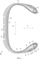
- Fig. 2 is a radial cut of a tire 10 in accordance with one exemplary embodiment.
- Various tissues, sometimes called products, composed of different materials can be present throughout the tire 10.
- the tread 20 of the tire 10 is shown as being located farthest from the axial center of the tire 10 in the radial direction 14.
- a first belt layer 64 and a second belt layer 66 are located below the tread 20 in the radial direction 14 and comprise belts for use in strengthening and holding the form of the tire 10.
- the reinforcement belts of the layers 64, 66 may be crossed relative to one another, and in some instances they can be arranged at an angle of 20 degrees to one another.
- the casing 22, or carcass, extends from the tread 20 and includes sidewalls of the tire 10 terminating in a pair of beads 24 that are arranged for mounting onto the rim of the wheel of the vehicle.
- a bead core 28 is located in each one of the beads 24 and is present to provide strength and a gripping force in the bead 24 for retention onto the rim.
- the left hand side bead 24 can be a mirror image of the right hand side bead 24 and both beads 24 can have products that are made of the same material. Some of the tissues/products are located only in the bead 24, while others are located in the bead 24 and extend therefrom.
- an inner liner 68 is inside of the bead 24 and extends to an inner, exterior side of the bead 24 before extending up the sidewall of the casing 22.
- the inner liner 68 then extends across the entire inner side of the crown in the axial direction 16 before extending into and forming the inner side of the right hand side wall of the casing 22.
- the inner liner 68 then terminates inside of the right hand side bead 24 and is arranged in a similar mirror-image manner to its presence in the left hand side bead 24.
- the tire 10 includes a tissue designated as a reinforcement ply 32 that is located within one of the beads 18 and extends through the casing 12 and crown to the other bead 18.
- the reinforcement ply 32 wraps around the bead core 20 and is designated as a return casing ply 34 in the location outward in the axial direction 28 from the bead core 20.
- Other tissues in the tire 10 such as a stiffener layer 40 and a bead filler 42 do not extend into the sidewalls of the casing 12 or the crown, but are instead only located in the bead 18. Relative positions in the axial direction 16 can be described with respect to inboard and outboard positions. The most inboard point of the tire 10 may be the radial direction line 14 shown in Fig.
- the center of the tire 10 is inboard of both of the beads 24 in the axial direction 16.
- the second bead layer 42 is outboard of the bead core 28 in the axial direction 16.
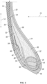
- Fig. 3 is a close up view of the left hand side bead 24 in accordance with another exemplary embodiment.
- the bead core 28 is made up of one or more steel rods.
- the bead core 28 is surrounded by the padding gum 30 and in some instances may be completely surrounded on all sides by the padding gum 30.
- Surrounding the bead core 28 is a wrapping tissue 44 that can be made of nylon in some embodiments.
- the rod making up the bead core 28 is shown as a single piece and has a rectangular cross-sectional shape. This single piece can actually be many rods arranged together in the shape of a rectangle.
- the bead core 28 can be made of multiple components and these components could have any cross-sectional shape.
- the wrapping tissue 44 wraps around the padding gum 30 and overlaps itself to form an overlap.
- the wrapping tissue 44 may have a stiffness of 14 MPa and can be made of a rubber mix and textile which in some instances can be a nylon ply, the padding gum 30 can be a rubber mix and may have a stiffness of 28 MPa, and the bead core 28 can be made of steel or aluminum and can have a stiffness of 30,000,000 MPa in some embodiments.
- the bead core 28 can be lightened so that a smaller rod can be used to improve performance properties of the tire 10.
- the bead 24 includes bead filler 36, sometimes referred to as gum stuffing, that is between and engages both the reinforcement ply 32 and the return casing ply 34.
- the wrapping tissue 44 engages the bead filler 36, the reinforcement ply 32, and the return casing ply 34.
- the wrapping tissue 44 functions to stabilize the geometry of the padding gum 30 and the bead core 28. If the wrapping tissue 44 were not present, the padding gum 30 would assume a more square shape upon formation, and would assume a more oval shape when the tire 10 is used.
- the wrapping tissue 44 thus causes the tissues of the bead 24 to be desirably shaped so that they can function in an intended manner.
- truck tires 10 can be made without a wrapping tissue 44 and can function in a completely normal and safe manner.
- the addition of a wrapping tissue 44 may provide an even higher bead 24 endurance performance than in those instances in which a wrapping tissue 44 is absent in the bead 24.
- the bead filler 36 is a rubber mix that is different than the rubber mix making up the padding gum 30.
- the material making up the bead filler 36 is more flexible than the material making up the padding gum 30.
- the bead filler 36 can have a stiffness from 3.6 MPa to 5.6MPa.
- the bead filler 36 engages the wrapping tissue 44, the reinforcement ply 32 and the return casing ply 34, and may extend from the reinforcement ply 32 to the return casing ply 34 in the axial direction 16.
- the bead filler 36 can be a material or composite material that has the same stiffness at all points, as distinguished from a two zone bead filler 36 that has a stiffer portion and a more flexible portion.
- the configuration of the bead 24 provides a way to use softer rubber which is desirable for impact and aging resistance.
- the bead filler 36 is a product that is not coextruded and can be a single, soft product as compared to some other stiffer products of the bead 24. In some exemplary embodiments, no product/portion of the bead 24 is formed by coextrusion or is a coextruded product.
- the return casing ply 34 is a portion of the reinforcement ply 32 that is on the outboard side of the bead core 28 in the axial direction 16. The return casing ply 34 may begin at the most inward portion of the reinforcement ply 32 in the radial direction 14.
- the bead filler 36 ends in the bead 24 or in some instances may be a product that extends into the sidewall of the tire 10. However, the bead filler 36 does not extend all the way under the belt layers 64, 66 to the other sidewall of the tire 10.
- the reinforcement ply 32 is a composite material that includes metal cords and a rubber mix. The reinforcement ply 32 in the direction of its cords is stiffer than the wrapping tissue 44, the bead filler 36, and the padding gum 30. The reinforcement ply 32 extends from the bead 24, through the sidewall, under the belt layers 64, 66, and then into the opposite sidewall and down into the bead 24 on the right hand side of the tire 10.
- the stiffener layer 38 is located outboard from the return casing ply 34 in the axial direction 16 and contacts the return casing ply 34 along a portion of its length.
- the stiffener layer 38 terminates in the bead 24 so that some of it is located inward in the radial direction 14 from the bead core 28. Other portions of the stiffener layer 38 are outward in the radial direction 14 from the bead core 28.
- the stiffener layer 38 can be made of a combination of steel and rubber, and this rubber may have a stiffness of 10 MPa.
- the bead 24 includes an anti-abrasive strip 46 that is on the outside of the bead 24 and designed to engage the rim.
- the anti-abrasive strip 46 engages the stiffener layer 38, but need not in other arrangements.
- the stiffener layer 38 in Fig. 3 extends outward in the radial direction 14 to have a portion outward of the bead core 28, and the return casing ply 34 in the radial direction 14.
- the first bead layer 40 is a product of the tire 10 made of rubber that has a portion located between and engaging the return casing ply 34 and the stiffener layer 38 in the axial direction 16.
- the first bead layer 40 extends outward in the radial direction 14 and engages the bead filler 36.
- the first bead layer 40 terminates at an outward radial terminal end 54 that is positioned inward of a portion of the bead filler 36 in the radial direction 14.
- the first bead layer 40 may terminate in the bead 24, and may or may not extend to the sidewall of the tire 10.
- the first bead layer 40 does not extend to be under the belt layers 64, 66, and does not extend to the right hand side sidewall or right hand side bead 24.
- the second bead layer 42 is likewise a product of the tire 10 made of rubber, and has a portion between and engaging the stiffener layer 38 and the anti-abrasive strip 46.
- the second bead layer 42 extends outward in the radial direction 14 and engages the first bead layer 40, terminating at an outward radial terminal end 56 that is short of the outward radial terminal end 54 so that a portion of the first bead layer 40 is outward in the radial direction 14 from the entire second bead layer 42.
- the outward radial terminal end 54 is outward in the radial direction 14 from the outward radial terminal end 56.
- An opposite inner radial terminal end 60 of the second bead layer 42 is located at an inner radial terminal end of the stiffener layer 38 and is outboard of the bead core 28 in the axial direction 16.
- the second bead layer 42 may extend into the sidewall of the tire 10, but does not extend over to the second sidewall or the right hand side bead 24 of the tire 10.
- the second bead layer 42 engages a sidewall product 70 that is in the sidewall and that may have a stiffness that is 3.6 to 5.6 MPa.
- the first bead layer 40 and the second bead layer 42 are both interior products of the tire 10 and do not have any portions that form the outer surface of the tire 10.
- the first bead layer 40 has a stiffness that is 8-14 MPa.
- the second bead layer 42 has a stiffness that is 8-14 MPa.
- the stiffness of the first bead layer 40 is the same as the stiffness of the second bead layer 42.
- the stiffness of the second bead layer 42 is different from the stiffness of the first bead layer 40.
- the first bead layer 40 can have a stiffness that is 8 MPa, 8.5 MPa, 14 MPa, 10 MPa, 11MPa, 12 MPa, from 9-13 MPa, from 10-12 MPa, or from 9.5-11.5 MPa in accordance with certain exemplary embodiments.
- the second bead layer 42 can have a stiffness that is 8 MPa, 8.5 MPa, 14 MPa, 10 MPa, 1 IMPa, 12 MPa, from 9-13 MPa, from 10-12 MPa, or from 9.5-11.5 MPa in accordance with certain exemplary embodiments.
- the stiffness of the first bead layer 40 and the stiffness of the second bead layer 42 are both greater than the stiffness of the bead filler 36 so that the first bead layer 40 and the second bead layer 42 are each more stiff than the bead filler 36.
- various stiffness amounts for the first and second bead layers 40, 42 employs a first bead layer 40 that has an 8.5 MPa stiffness, and a second bead layer 42 that has an 8.5 MPa stiffness.
- the provided design does not use a stiff product directly against the reinforcement ply 32 interior (inboard in the axial direction 16) side.
- the current design spreads hydrostatic stresses from the rim flange over a much larger zone than if the stiff layer were against the reinforcement ply 32. This spreading reduces concentrated bending spots in the reinforcement ply 32 over the entire region of the bead 24, thus improving fatigue performance of the reinforcement ply 32.
- the present configuration provides resistance to casing ply unwrapping because of the rigid and cohesive first bead layer 40 shearing against the return side of the casing ply.
- the first and second bead layers 40 and 42 also provide rigidity to the working (interior side) of the casing ply to resist fatigue.
- the present application describes the stiffness of a product or material.
- the stiffness that is being referred to is the Young's modulus which is the stiffness of an elastic material, or elastic modulus.
- the stiffness is provided in measurements of mega pascals (MPa).
- the stiffness material property in question that is being referred to is MA10. This stiffness property can be calculated using French standard NF T 46-002, September 1988.
- Tape 48 is located in the bead 24 and engages the second bead layer 42, the stiffener layer 38, and the first bead layer 40.
- the tape 48 may be present on the end of the stiffener layer 38 when the stiffener layer 38 is assembled into the green tire 10 before curing.
- the tape could be wrapped around the outward radial terminal end 58 in this regard before and after assembly of the stiffener layer 38 into the tire 10.
- the tape 48 is shown as being present, it is to be understood that the tape 48 is not present in the tire 10 in other exemplary embodiments of the tire 10.
- the provided configuration of the bead 24 allows the elimination of tape 48 at the ends of all products thus decreasing cost of the tire 10 and reducing complexity of the tire 10.
- FIG. 4 An alternate design of the bead 24 is illustrated in Fig. 4 which again shows the left hand bead 24 (the right side bead 24 being a mirror image) in cross-section.
- the products of the Fig. 4 design and their arrangement are the same as that previously discussed and a repeat of this information is not necessary.
- the lengths of the bead layers 40, 42 are shortened in the radial direction 14 so that they are shorter in the Fig. 4 embodiment than in the Fig. 3 embodiment.
- the bead layers 40, 42 extend in the radial direction 14 so that the outward radial terminal ends 54, 56 terminate at an outward radial terminal end 58 of the stiffener layer 38 in the radial direction 14.
- This termination may be exactly at the radial position of the end 58, or the three ends 54, 56, 58 could be not exactly at the same position in the radial direction 14 but could be very close to one another such as a few millimeters to one another in the radial direction 14.
- ends 54, 56, 58 could be up to 7 millimeters difference in location in the radial direction 14 but still be considered to be terminating at the same radial location due to this close proximity.
- the Fig. 4 embodiment likewise differs from the Fig. 3 embodiment in that a product that is a first flexible layer 50 is present that engages the outward radial terminal end 54 and extends outward in the radial direction 14 to engage the bead filler 36, the sidewall product 70, and the second flexible layer 52.
- the first flexible layer 50 extends farther outward in the radial direction 14 than the second flexible layer 52.
- the second flexible layer 52 engages the outward radial terminal end 56 and extends outward in the radial direction 14 terminating short of the termination point of the first flexible layer 50.
- the second flexible layer 52 additionally engages the first flexible layer 50, the sidewall product 70, and the anti-abrasive strip 46.
- the majority of the second flexible layer 52 is located outboard from the first flexible layer 50 in the axial direction 16.
- the stiffness of the first flexible layer 50 is less than the stiffness of the first bead layer 40 and the stiffness of the second bead layer 42.
- the stiffness of the second flexible layer 52 is less than the stiffness of layers 40 and 42.
- the stiffness of the first flexible layer 50 is 3.6-5.6 MPa
- the stiffness of the second flexible layer 52 is 3.6-5.6 MPa.
- the first and second flexible layers 50, 52 are softer and have lower hysteresis than the layers 40 and 42.
- the stiffness of the first flexible layer 50 may be the same as the stiffness of the second flexible layer 52, or they can be different from one another.
- FIG. 6 Another exemplary embodiment of the bead 24 of the tire 10 is shown in Fig. 6 that includes an additional product that is the third bead layer 62.
- the third bead layer 62 is located between the bead filler 36 and the return casing ply 34 in the axial direction 16 and engages both of these products, and the third bead layer 62 engages the wrapping tissue 44 of the bead 24 and extends outward in the radial direction 14 from the bead 24.
- the third bead layer 62 has a stiffness that is 8-14 MPa.
- the heated rim performance may sometimes be known as casing ply unwrapping.
- the heated rim performance may be equivalent to other designs that use textile or metallic reinforcements to achieve the desired level of heated rim performance.
- the present tire 10 may thus be provided so that textile or metallic reinforcements for heated rim performance are not present, although it is to be understood that they may in fact be present in some exemplary embodiments.
Landscapes
- Engineering & Computer Science (AREA)
- Mechanical Engineering (AREA)
- Tires In General (AREA)
Description
- The subject matter of the present invention relates to a truck tire that has a bead design that has stiff outer bead products. More particularly, the present application involves a bead design that features stiff products strategically placed to reduce or eliminate bending hot spots and to improve resistance to heat. Even more particularly, the present invention relates to a heavy truck tire according to the preamble of independent claim 1, such as it is e.g. known from
WO2019108207A1 . - Heavy commercial truck tires have a tread area that engages the road surface, and a carcass with sidewalls that extend from the tread area. The sidewalls terminate in beads that are designed to engage a rim of the wheel. The beads include a bead core made of steel and other bead tissues that can be composed of rubber. In order to improve performance of the truck tire it is desirable to lighten the weight of the bead core, for example by reducing the number of rods of the bead core. However, reduction in the size of the bead core causes more flexing in the tire. To compensate for this flexing the area radially above the bead core, sometimes referred to as bead filler, includes a rubber portion that is more stiff. This bead filler is coextruded so that the stiffer rubber first portion is on the inboard side of the tire in the axial direction, and the more flexible second portion is on the outboard side of the tire in the axial direction. However, the use of a two zone bead filler requires these products to be formed via coextrusion which can add cost and complexity to the manufacturing process. Additionally, the use of a two zone bead filler does not eliminate the magnitude of bending caused by the bead core, but simply moves this bending to a location more outward in the radial direction. With this design, additional products outboard in the radial direction, which are sometimes referred to as a first bead layer and a second bead layer, are made of rubber materials that have the same stiffness as the flexible second portion.
- The first and second bead layers are made of materials that are more flexible than the stiff first portion of the bead filler, and may have a stiffness of 3.6 with reasonably high cohesion properties. It is also known to provide first and second bead layers that have a higher stiffness at 5.5 MPa that achieve lower hysteresis but with the compromise of lower cohesion. Even at 5.5 MPa, the material making up the bead layers in this version is still more flexible than the stiffer mixes in the stiffer rubber first portion of the bead filler. In addition to the coextruded, two portion bead core, a chafer is included that wraps completely around the bead core. These configurations are difficult to build, expensive, and leaves the end of the turnup ply exposed. As such, there is a need to reduce or eliminate a bending hot spot in heavy truck tires, and to improve heated rim performance of the tire without adding significant cost to the tire.
- A full and enabling disclosure of the present invention, including the best mode thereof, directed to one of ordinary skill in the art, is set forth in the specification, which makes reference to the appended figures, in which:
-
Fig. 1 is a perspective view of a heavy truck tire. -
Fig. 2 is a cross-sectional view of a radial cut of a truck tire with all items in cross-section as the tire would look when mounted to a rim. -
Fig. 3 is a cross-sectional view of a bead as it would look when mounted to a rim in accordance with one exemplary embodiment. -
Fig. 4 is a cross-sectional view of a bead that has first and second flexible layers in accordance with another exemplary embodiment. -
Fig. 5 is a cross-sectional view of a bead that has a second bead layer that extends under the bead core in accordance with yet another exemplary embodiment. -
Fig. 6 is a cross-sectional view of a bead that has a third bead layer in accordance with a still further exemplary embodiment. - The use of identical or similar reference numerals in different figures denotes identical or similar features.
- Reference will now be made in detail to embodiments of the invention, one or more examples of which are illustrated in the drawings. Each example is provided by way of explanation of the invention, and not meant as a limitation of the invention. For example, features illustrated or described as part of one embodiment can be used with another embodiment to yield still a third embodiment.
- The present invention provides for a
bead 24 design of a heavyduty truck tire 10 that features first andsecond bead layers bead filler 36 portion of thebead 24. The stiffness of the first andsecond bead layers bead 24 reduces or eliminates a bending hot spot that may or may not be present just above thebead core 28. Further, this configuration may achieve higher heat resistance in thetire 10 such as improved heated rim performance. The provided design achieves casing ply unwrapping under high heat and load while at the same time providing improved resistance to casing ply fatigue in the bead zone. The provided configuration offers a way to avoid extending the chafer ply under thebead core 28, which poses significant fabrication issues, including uniformity, which increases fabrication costs. -
Fig. 1 shows atire 10 that is a heavyduty truck tire 10. In this regard, thetire 10 is not designed for nor used with a car, motorcycle, or light truck (payload capacity less than 4,000 pounds), but is instead designed for and used with heavy duty trucks such as 18 wheelers, garbage trucks, or box trucks. Thetire 10 may be a steer tire, a drive tire, a trailer tire, or an all position tire. Thetire 10 includes acasing 22 onto which atread 20 is disposed thereon. Thebead 24 is a part of thecasing 22 that is at the inner radial end of thecasing 22 closest to thecentral axis 12. Thecentral axis 12 of thetire 10 extends through the center of thecasing 22, and theaxial direction 16 of thetire 10 is parallel to thecentral axis 12. Theradial direction 14 of thetire 10 is perpendicular to thecentral axis 12, and thetread 20 is located farther from thecentral axis 12 in theradial direction 14 than thecasing 22. Thetread 20 extends all the way around thecasing 22 in thecircumferential direction 18 of thetire 10 and circles thecentral axis 12 by 360 degrees. -
Fig. 2 is a radial cut of atire 10 in accordance with one exemplary embodiment. Various tissues, sometimes called products, composed of different materials can be present throughout thetire 10. Thetread 20 of thetire 10 is shown as being located farthest from the axial center of thetire 10 in theradial direction 14. Afirst belt layer 64 and asecond belt layer 66 are located below thetread 20 in theradial direction 14 and comprise belts for use in strengthening and holding the form of thetire 10. The reinforcement belts of thelayers casing 22, or carcass, extends from thetread 20 and includes sidewalls of thetire 10 terminating in a pair ofbeads 24 that are arranged for mounting onto the rim of the wheel of the vehicle. Abead core 28 is located in each one of thebeads 24 and is present to provide strength and a gripping force in thebead 24 for retention onto the rim. The lefthand side bead 24 can be a mirror image of the righthand side bead 24 and bothbeads 24 can have products that are made of the same material. Some of the tissues/products are located only in thebead 24, while others are located in thebead 24 and extend therefrom. For instance, aninner liner 68 is inside of thebead 24 and extends to an inner, exterior side of thebead 24 before extending up the sidewall of thecasing 22. Theinner liner 68 then extends across the entire inner side of the crown in theaxial direction 16 before extending into and forming the inner side of the right hand side wall of thecasing 22. Theinner liner 68 then terminates inside of the righthand side bead 24 and is arranged in a similar mirror-image manner to its presence in the lefthand side bead 24. Theinner liner 68 is thus a product of thetire 10 that extends all the way from onebead 24 to theother bead 24 and is made of a material that is fluid tight so that fluid between thetire 10 and rim is maintained therein for purposes of maintaining inflation pressure of thetire 10. - The
tire 10 includes a tissue designated as areinforcement ply 32 that is located within one of thebeads 18 and extends through thecasing 12 and crown to theother bead 18. Thereinforcement ply 32 wraps around thebead core 20 and is designated as areturn casing ply 34 in the location outward in theaxial direction 28 from thebead core 20. Other tissues in thetire 10 such as astiffener layer 40 and abead filler 42 do not extend into the sidewalls of thecasing 12 or the crown, but are instead only located in thebead 18. Relative positions in theaxial direction 16 can be described with respect to inboard and outboard positions. The most inboard point of thetire 10 may be theradial direction line 14 shown inFig. 2 as it is located at the center of thetire 10 in theaxial direction 16. The center of thetire 10 is inboard of both of thebeads 24 in theaxial direction 16. As another example, thesecond bead layer 42 is outboard of thebead core 28 in theaxial direction 16. -
Fig. 3 is a close up view of the lefthand side bead 24 in accordance with another exemplary embodiment. Thebead core 28 is made up of one or more steel rods. Thebead core 28 is surrounded by thepadding gum 30 and in some instances may be completely surrounded on all sides by thepadding gum 30. Surrounding thebead core 28 is a wrappingtissue 44 that can be made of nylon in some embodiments. The rod making up thebead core 28 is shown as a single piece and has a rectangular cross-sectional shape. This single piece can actually be many rods arranged together in the shape of a rectangle. However, in other embodiments thebead core 28 can be made of multiple components and these components could have any cross-sectional shape. The wrappingtissue 44 wraps around thepadding gum 30 and overlaps itself to form an overlap. The wrappingtissue 44 may have a stiffness of 14 MPa and can be made of a rubber mix and textile which in some instances can be a nylon ply, thepadding gum 30 can be a rubber mix and may have a stiffness of 28 MPa, and thebead core 28 can be made of steel or aluminum and can have a stiffness of 30,000,000 MPa in some embodiments. Thebead core 28 can be lightened so that a smaller rod can be used to improve performance properties of thetire 10. - The
bead 24 includesbead filler 36, sometimes referred to as gum stuffing, that is between and engages both the reinforcement ply 32 and thereturn casing ply 34. The wrappingtissue 44 engages thebead filler 36, thereinforcement ply 32, and thereturn casing ply 34. The wrappingtissue 44 functions to stabilize the geometry of thepadding gum 30 and thebead core 28. If the wrappingtissue 44 were not present, thepadding gum 30 would assume a more square shape upon formation, and would assume a more oval shape when thetire 10 is used. The wrappingtissue 44 thus causes the tissues of thebead 24 to be desirably shaped so that they can function in an intended manner. It is to be understood thatother truck tires 10 can be made without a wrappingtissue 44 and can function in a completely normal and safe manner. The addition of a wrappingtissue 44 may provide an evenhigher bead 24 endurance performance than in those instances in which awrapping tissue 44 is absent in thebead 24. However,various truck tire 10 designs exist that are fully functional and safe that both include and do not include a wrappingtissue 44. - The
bead filler 36 is a rubber mix that is different than the rubber mix making up thepadding gum 30. The material making up thebead filler 36 is more flexible than the material making up thepadding gum 30. Thebead filler 36 can have a stiffness from 3.6 MPa to 5.6MPa. Thebead filler 36 engages the wrappingtissue 44, the reinforcement ply 32 and thereturn casing ply 34, and may extend from the reinforcement ply 32 to the return casing ply 34 in theaxial direction 16. Thebead filler 36 can be a material or composite material that has the same stiffness at all points, as distinguished from a twozone bead filler 36 that has a stiffer portion and a more flexible portion. The configuration of thebead 24 provides a way to use softer rubber which is desirable for impact and aging resistance. Thebead filler 36 is a product that is not coextruded and can be a single, soft product as compared to some other stiffer products of thebead 24. In some exemplary embodiments, no product/portion of thebead 24 is formed by coextrusion or is a coextruded product. The return casing ply 34 is a portion of the reinforcement ply 32 that is on the outboard side of thebead core 28 in theaxial direction 16. The return casing ply 34 may begin at the most inward portion of the reinforcement ply 32 in theradial direction 14. Thebead filler 36 ends in thebead 24 or in some instances may be a product that extends into the sidewall of thetire 10. However, thebead filler 36 does not extend all the way under the belt layers 64, 66 to the other sidewall of thetire 10. The reinforcement ply 32 is a composite material that includes metal cords and a rubber mix. The reinforcement ply 32 in the direction of its cords is stiffer than the wrappingtissue 44, thebead filler 36, and thepadding gum 30. The reinforcement ply 32 extends from thebead 24, through the sidewall, under the belt layers 64, 66, and then into the opposite sidewall and down into thebead 24 on the right hand side of thetire 10. - The
stiffener layer 38 is located outboard from the return casing ply 34 in theaxial direction 16 and contacts the return casing ply 34 along a portion of its length. Thestiffener layer 38 terminates in thebead 24 so that some of it is located inward in theradial direction 14 from thebead core 28. Other portions of thestiffener layer 38 are outward in theradial direction 14 from thebead core 28. Thestiffener layer 38 can be made of a combination of steel and rubber, and this rubber may have a stiffness of 10 MPa. Thebead 24 includes ananti-abrasive strip 46 that is on the outside of thebead 24 and designed to engage the rim. Theanti-abrasive strip 46 engages thestiffener layer 38, but need not in other arrangements. Thestiffener layer 38 inFig. 3 extends outward in theradial direction 14 to have a portion outward of thebead core 28, and the return casing ply 34 in theradial direction 14. - The
first bead layer 40 is a product of thetire 10 made of rubber that has a portion located between and engaging the return casing ply 34 and thestiffener layer 38 in theaxial direction 16. Thefirst bead layer 40 extends outward in theradial direction 14 and engages thebead filler 36. Thefirst bead layer 40 terminates at an outward radialterminal end 54 that is positioned inward of a portion of thebead filler 36 in theradial direction 14. Thefirst bead layer 40 may terminate in thebead 24, and may or may not extend to the sidewall of thetire 10. However, thefirst bead layer 40 does not extend to be under the belt layers 64, 66, and does not extend to the right hand side sidewall or righthand side bead 24. Thesecond bead layer 42 is likewise a product of thetire 10 made of rubber, and has a portion between and engaging thestiffener layer 38 and theanti-abrasive strip 46. Thesecond bead layer 42 extends outward in theradial direction 14 and engages thefirst bead layer 40, terminating at an outward radialterminal end 56 that is short of the outward radialterminal end 54 so that a portion of thefirst bead layer 40 is outward in theradial direction 14 from the entiresecond bead layer 42. The outward radialterminal end 54 is outward in theradial direction 14 from the outward radialterminal end 56. An opposite inner radialterminal end 60 of thesecond bead layer 42 is located at an inner radial terminal end of thestiffener layer 38 and is outboard of thebead core 28 in theaxial direction 16. As with thefirst bead layer 40, thesecond bead layer 42 may extend into the sidewall of thetire 10, but does not extend over to the second sidewall or the righthand side bead 24 of thetire 10. Thesecond bead layer 42 engages asidewall product 70 that is in the sidewall and that may have a stiffness that is 3.6 to 5.6 MPa. Thefirst bead layer 40 and thesecond bead layer 42 are both interior products of thetire 10 and do not have any portions that form the outer surface of thetire 10. - The
first bead layer 40 has a stiffness that is 8-14 MPa. Likewise, thesecond bead layer 42 has a stiffness that is 8-14 MPa. In some embodiments the stiffness of thefirst bead layer 40 is the same as the stiffness of thesecond bead layer 42. In other embodiments the stiffness of thesecond bead layer 42 is different from the stiffness of thefirst bead layer 40. Thefirst bead layer 40 can have a stiffness that is 8 MPa, 8.5 MPa, 14 MPa, 10 MPa, 11MPa, 12 MPa, from 9-13 MPa, from 10-12 MPa, or from 9.5-11.5 MPa in accordance with certain exemplary embodiments. Thesecond bead layer 42 can have a stiffness that is 8 MPa, 8.5 MPa, 14 MPa, 10 MPa, 1 IMPa, 12 MPa, from 9-13 MPa, from 10-12 MPa, or from 9.5-11.5 MPa in accordance with certain exemplary embodiments. The stiffness of thefirst bead layer 40 and the stiffness of thesecond bead layer 42 are both greater than the stiffness of thebead filler 36 so that thefirst bead layer 40 and thesecond bead layer 42 are each more stiff than thebead filler 36. Although various stiffness amounts for the first and second bead layers 40, 42 are provided, the preferred embodiment employs afirst bead layer 40 that has an 8.5 MPa stiffness, and asecond bead layer 42 that has an 8.5 MPa stiffness. - The first and second bead layers 40, 42 extend so as to have a portion be inward in the
radial direction 14 from the farthest inward radial extent of thereturn casing ply 34. Thefirst bead layer 40 completely fills the void, with the exception possibly oftape 48, between the return casing ply 34 and thestiffener layer 38, sometimes referred to as a chafer. Thesecond bead layer 42 should completely fill the void, with the exception of possiblytape 48, between thestiffener layer 38 and theanti-abrasive strip 46. The provided design thus utilizesstiffer products bead 24. Further, the provided design does not use a stiff product directly against the reinforcement ply 32 interior (inboard in the axial direction 16) side. The current design spreads hydrostatic stresses from the rim flange over a much larger zone than if the stiff layer were against thereinforcement ply 32. This spreading reduces concentrated bending spots in the reinforcement ply 32 over the entire region of thebead 24, thus improving fatigue performance of thereinforcement ply 32. The present configuration provides resistance to casing ply unwrapping because of the rigid and cohesivefirst bead layer 40 shearing against the return side of the casing ply. The first and second bead layers 40 and 42 also provide rigidity to the working (interior side) of the casing ply to resist fatigue. - The present application describes the stiffness of a product or material. The stiffness that is being referred to is the Young's modulus which is the stiffness of an elastic material, or elastic modulus. The stiffness is provided in measurements of mega pascals (MPa). The stiffness material property in question that is being referred to is MA10. This stiffness property can be calculated using French standard NF T 46-002, September 1988.
-
Tape 48 is located in thebead 24 and engages thesecond bead layer 42, thestiffener layer 38, and thefirst bead layer 40. Thetape 48 may be present on the end of thestiffener layer 38 when thestiffener layer 38 is assembled into thegreen tire 10 before curing. The tape could be wrapped around the outward radialterminal end 58 in this regard before and after assembly of thestiffener layer 38 into thetire 10. Although thetape 48 is shown as being present, it is to be understood that thetape 48 is not present in thetire 10 in other exemplary embodiments of thetire 10. The provided configuration of thebead 24 allows the elimination oftape 48 at the ends of all products thus decreasing cost of thetire 10 and reducing complexity of thetire 10. - An alternate design of the
bead 24 is illustrated inFig. 4 which again shows the left hand bead 24 (theright side bead 24 being a mirror image) in cross-section. The products of theFig. 4 design and their arrangement are the same as that previously discussed and a repeat of this information is not necessary. However, there are some differences in the configuration of the first and second bead layers 40 and 42. The lengths of the bead layers 40, 42 are shortened in theradial direction 14 so that they are shorter in theFig. 4 embodiment than in theFig. 3 embodiment. The bead layers 40, 42 extend in theradial direction 14 so that the outward radial terminal ends 54, 56 terminate at an outward radialterminal end 58 of thestiffener layer 38 in theradial direction 14. This termination may be exactly at the radial position of theend 58, or the three ends 54, 56, 58 could be not exactly at the same position in theradial direction 14 but could be very close to one another such as a few millimeters to one another in theradial direction 14. As such, when described as having ends that terminate in the same radial location it is to be understood that there can be some tolerance in the regard, and theends radial direction 14 but still be considered to be terminating at the same radial location due to this close proximity. - The
Fig. 4 embodiment likewise differs from theFig. 3 embodiment in that a product that is a firstflexible layer 50 is present that engages the outward radialterminal end 54 and extends outward in theradial direction 14 to engage thebead filler 36, thesidewall product 70, and the secondflexible layer 52. The firstflexible layer 50 extends farther outward in theradial direction 14 than the secondflexible layer 52. The secondflexible layer 52 engages the outward radialterminal end 56 and extends outward in theradial direction 14 terminating short of the termination point of the firstflexible layer 50. The secondflexible layer 52 additionally engages the firstflexible layer 50, thesidewall product 70, and theanti-abrasive strip 46. The majority of the secondflexible layer 52 is located outboard from the firstflexible layer 50 in theaxial direction 16. - The stiffness of the first
flexible layer 50 is less than the stiffness of thefirst bead layer 40 and the stiffness of thesecond bead layer 42. Likewise, the stiffness of the secondflexible layer 52 is less than the stiffness oflayers flexible layer 50 is 3.6-5.6 MPa, and the stiffness of the secondflexible layer 52 is 3.6-5.6 MPa. The first and secondflexible layers layers flexible layer 50 may be the same as the stiffness of the secondflexible layer 52, or they can be different from one another. The stiffness of thebead filler 36 may be the same as the stiffness of the firstflexible layer 50, and can be the same as the stiffness of the secondflexible layer 52, or can be different than theselayers Fig. 4 still provides the cohesion and rigidity needed to resist reinforcement ply 32 fatigue and unwrapping, while keeping lower hysteresis and rigidity in the upper part of thebead 24 zone where there is more deflection. In this upper zone, the rigidity is not needed and the higher hysteresis contributes to a higher rolling resistance of thetire 10 which is not desired. - Another exemplary embodiment of the
tire 10 is shown inFig. 5 that includes products configured like those ofFig. 4 such that a repeat of this information is not necessary. The difference inFig. 5 concerns thesecond bead layer 42 that extends a farther distance inward in theradial direction 14 than it does in theFig. 3 or4 embodiments. Here, thesecond bead layer 42 wraps around a portion of thebead core 28 and terminates at a location in theradial direction 14 that is inward of theentire bead core 28, theentire bead filler 36, the entirefirst bead layer 40, and theentire stiffener layer 38. As described herein, when a component is wrapped around another it may or may not engage that component. Thesecond bead layer 42 engages thereturn casing ply 34. If thesecond bead layer 42 is extended far enough, additional casing ply unwrapping performance could be expected as well as resistance to mounting damage. The illustrated arrangement of thesecond bead layer 42 inFig. 5 can be used with any of the variously described embodiments of thebead 24 of thetire 10 herein and need not be only used in connection with theFig. 4 embodiment. - Another exemplary embodiment of the
bead 24 of thetire 10 is shown inFig. 6 that includes an additional product that is thethird bead layer 62. Thethird bead layer 62 is located between thebead filler 36 and the return casing ply 34 in theaxial direction 16 and engages both of these products, and thethird bead layer 62 engages the wrappingtissue 44 of thebead 24 and extends outward in theradial direction 14 from thebead 24. Thethird bead layer 62 has a stiffness that is 8-14 MPa. The stiffness of thethird bead layer 62 can be the same as the stiffness of the first and second bead layers 40 and 42 and may be greater than the stiffness of the bead filler36, and the first and secondflexible layers layers third bead layer 62 extends in theradial direction 14 outward to the outer terminal end of the return casing ply 34 and terminates here to share the same location in theradial direction 14. Thethird bead layer 62 will addadditional casing 22 ply unwrapping and fatigue performance. Thethird bead layer 62 has a cross-sectional size that is less than thebead filler 36, and is located in an outboard region in theaxial direction 16 of thebead 24 where stiffness is strategically employed as herein described. Although shown in connection with theFig. 5 embodiment, thethird bead layer 62 can be inserted into any of the other embodiments shown and described. - Although the present design was made to attempt to spread out stresses for casing ply fatigue performance, a large gain in heated rim performance was observed. The heated rim performance may sometimes be known as casing ply unwrapping. The heated rim performance may be equivalent to other designs that use textile or metallic reinforcements to achieve the desired level of heated rim performance. The
present tire 10 may thus be provided so that textile or metallic reinforcements for heated rim performance are not present, although it is to be understood that they may in fact be present in some exemplary embodiments.
Claims (13)
- A heavy truck tire (10) that has a central axis (12), a radial direction (14), and an axial direction (16), comprising:a tread (20);a casing (22) that carries the tread (20), wherein the casing (22) has a bead (18, 24) that has:a bead core (20, 28) that has a rod and padding gum (30);a reinforcement ply (32) that wraps around a section of the bead core (20, 28), wherein the reinforcement ply (32) has a return casing ply (34) a portion of which is outboard in the axial direction (16) from the bead core (20, 28);a bead filler (36) that has a portion radially outward from the bead core (20, 28) in the radial direction (14) and axially inboard from the return casing ply (34) in the axial direction (16);a stiffener layer (38) that has a portion located outboard from the return casing ply (34) in the axial direction (16);a first bead layer (40) that has a portion that is between the return casing ply (34) and the stiffener layer (38) in the axial direction (16);a second bead layer (42) that has a portion that is outboard from the stiffener layer (38);characterized in thatthe stiffness of the first bead layer (40) is 8 MPa to 14 MPa when calculated as the Young's modulus MA10 using French standard NF T 46-002, September 1988;the stiffness of the second bead layer (42) is 8 MPa to 14 MPa when calculated as the Young's modulus MA10 using French standard NF T 46-002, September 1988;wherein the stiffness of the bead filler (36) is less than the stiffness of the first bead layer (40), and wherein the stiffness of the bead filler (36) is less than the stiffness of the second bead layer (42).
- The tire (10) as set forth in claim 1, wherein the stiffness of the bead filler (36) is 3.6 to 5.6 MPa.
- The tire (10) as set forth in claim 1 or 2, wherein the bead (18, 24) has padding gum (30) that engages the bead core (20, 28) and has wrapping tissue (44) that engages the padding gum (30) and extends around the bead core (20, 28), wherein the wrapping tissue (44) engages the reinforcement ply (32) as the reinforcement ply (32) wraps around the section of the bead core (20, 28), wherein the bead core (20, 28) is free from engagement with the reinforcement ply (32).
- The tire (10) as set forth in any one of claims 1-3, wherein the stiffness of the first bead layer (40) is the same as the stiffness of the second bead layer (42).
- The tire (10) as set forth in any one of claims 1-4, wherein the bead (18, 24) has an anti-abrasive strip (46) that has a portion located outboard in the axial direction (16) from the second bead layer (42), wherein the anti-abrasive strip (46) has a portion located radially inward from the bead core (20, 28), wherein a portion of the second bead layer (42) is located between the stiffener layer (38) and the anti-abrasive strip (46) in the axial direction (16).
- The tire (10) as set forth in any one of claims 1-5, wherein the bead (18, 24) has tape (48) that engages the first bead layer (40), the second bead layer (42), and the return casing ply (34).
- The tire (10) as set forth in any one of claims 1-6, wherein the bead (18, 24) has a first flexible layer (50) that engages the first bead layer (40) and that has a portion located outward from the first bead layer (40) in the radial direction (14), wherein the stiffness of the first flexible layer (50) is 3.6 to 5.6 MPa; and
wherein the bead (18, 24) has a second flexible layer (52) that engages the second bead layer (42) and that has a portion located outward from the second bead layer (42) in the radial direction (14), wherein the stiffness of the second flexible layer (52) is 3.6 to 5.6 MPa. - The tire (10) as set forth in claim 7, wherein the first bead layer (40) and the second bead layer (42) extend in the radial direction (14) to tenninate at outward radial terminal ends (54, 56) that are located at the same location in the radial direction (14) as an outward radial terminal end (54, 56) of the stiffener layer (38).
- The tire (10) as set forth in claim 7 or 8, wherein the first flexible layer (50) and the second flexible layer (52) have a stiffness that is the same as the stiffness of the bead filler (36).
- The tire (10) as set forth in any one of claims 7-9, wherein the first flexible layer (50) engages the bead filler (36), and wherein the first flexible layer (50) engages the second flexible layer (52).
- The tire (10) as set forth in any one of claims 1-10, wherein the second bead layer (42) engages the return casing ply (34), wherein the second bead layer (42) has an inner radial terminal end (60) that is located inward in the radial direction (14) from the entire bead core (20, 28), the entire first bead layer (40), and the entire bead filler (36).
- The tire (10) as set forth in any one of claims 1-7, wherein the bead (18, 24) has a third bead layer (62) that engages the return casing ply (34) and that engages the bead filler (36), wherein the third bead layer (62) is located inboard in the axial direction (16) relative to a portion of the return casing ply (34), wherein the third bead layer (62) is located outboard in the axial direction (16) relative to a portion of the bead filler (36, 42), wherein the stiffness of the third bead layer (62) is 8 MPa to 14 MPa.
- The tire (10) as set forth in claim 12, wherein the stiffness of the third bead layer (62) is the same as the stiffness of the first bead layer (40), and wherein the stiffness of the third bead layer (62) is the same as the stiffness of the second bead layer (42).
Applications Claiming Priority (1)
| Application Number | Priority Date | Filing Date | Title |
|---|---|---|---|
| PCT/US2019/067132 WO2021126187A1 (en) | 2019-12-18 | 2019-12-18 | Truck tire with stiff outer bead products |
Publications (2)
| Publication Number | Publication Date |
|---|---|
| EP4076997A1 EP4076997A1 (en) | 2022-10-26 |
| EP4076997B1 true EP4076997B1 (en) | 2025-04-09 |
Family
ID=69187925
Family Applications (1)
| Application Number | Title | Priority Date | Filing Date |
|---|---|---|---|
| EP19842467.3A Active EP4076997B1 (en) | 2019-12-18 | 2019-12-18 | Truck tire with stiff outer bead products |
Country Status (4)
| Country | Link |
|---|---|
| US (1) | US12070972B2 (en) |
| EP (1) | EP4076997B1 (en) |
| CN (1) | CN114667224B (en) |
| WO (1) | WO2021126187A1 (en) |
Families Citing this family (6)
| Publication number | Priority date | Publication date | Assignee | Title |
|---|---|---|---|---|
| FR3129321B1 (en) | 2021-11-25 | 2024-10-11 | Michelin & Cie | Tire with improved rolling resistance performance |
| FR3129323B1 (en) | 2021-11-25 | 2024-10-11 | Michelin & Cie | Tire with improved rolling resistance performance |
| FR3129324B1 (en) | 2021-11-25 | 2024-04-05 | Michelin & Cie | Tire with improved rolling resistance performance |
| CN120641280A (en) * | 2023-01-12 | 2025-09-12 | 米其林集团总公司 | Tires with recycled rubber in the beads |
| JP2024124971A (en) * | 2023-03-03 | 2024-09-13 | 住友ゴム工業株式会社 | Pneumatic tires |
| US12220948B1 (en) | 2023-12-07 | 2025-02-11 | The Goodyear Tire & Rubber Company | Pneumatic tire bead and sidewall construction |
Family Cites Families (12)
| Publication number | Priority date | Publication date | Assignee | Title |
|---|---|---|---|---|
| DE2715734A1 (en) * | 1977-04-07 | 1978-10-19 | Uniroyal Ag | HEAVY-DUTY VEHICLE TIRES, IN PARTICULAR TUBELESS TIRES FOR TRUCKS OR DGL. |
| MY103255A (en) * | 1987-04-17 | 1993-05-29 | Goodyear Tire & Rubber | A pneumatic tire |
| US6422280B1 (en) * | 1997-01-30 | 2002-07-23 | The Goodyear Tire & Rubber Company | Heavy duty tire with specified bead design |
| US7322339B1 (en) * | 2006-09-11 | 2008-01-29 | Gm Global Technology Operations, Inc. | Apparent torque reserve at idle for direct injected engines |
| ATE517769T1 (en) * | 2007-10-03 | 2011-08-15 | Pirelli | TIRES WITH AN IMPROVED BEAD STRUCTURE |
| US20130056126A1 (en) * | 2011-09-06 | 2013-03-07 | Kiyoshi Ueyoko | Aircraft tire |
| JP6790845B2 (en) * | 2017-01-13 | 2020-11-25 | 住友ゴム工業株式会社 | Pneumatic tires for heavy loads |
| WO2019002726A1 (en) | 2017-06-27 | 2019-01-03 | Compagnie Generale Des Etablissements Michelin | Lightweight tyre |
| CN111491811A (en) * | 2017-11-30 | 2020-08-04 | 米其林集团总公司 | Pneumatic tire |
| US20190184765A1 (en) * | 2017-12-15 | 2019-06-20 | The Goodyear Tire & Rubber Company | Pneumatic tire with a robust ply ending structure |
| US20190184766A1 (en) * | 2017-12-15 | 2019-06-20 | The Goodyear Tire & Rubber Company | Pneumatic tire with a robust bead area structure |
| US11673431B2 (en) * | 2018-05-30 | 2023-06-13 | Compagnie Generale Des Etablissements Michelin | Truck tire with contention armature overlap |
-
2019
- 2019-12-18 CN CN201980102121.8A patent/CN114667224B/en active Active
- 2019-12-18 US US17/780,575 patent/US12070972B2/en active Active
- 2019-12-18 WO PCT/US2019/067132 patent/WO2021126187A1/en not_active Ceased
- 2019-12-18 EP EP19842467.3A patent/EP4076997B1/en active Active
Also Published As
| Publication number | Publication date |
|---|---|
| BR112022008025A2 (en) | 2022-07-12 |
| US12070972B2 (en) | 2024-08-27 |
| CN114667224A (en) | 2022-06-24 |
| WO2021126187A1 (en) | 2021-06-24 |
| EP4076997A1 (en) | 2022-10-26 |
| US20220410638A1 (en) | 2022-12-29 |
| CN114667224B (en) | 2023-06-20 |
Similar Documents
| Publication | Publication Date | Title |
|---|---|---|
| EP4076997B1 (en) | Truck tire with stiff outer bead products | |
| EP0605177B1 (en) | Pneumatic tire | |
| JP6209151B2 (en) | tire | |
| EP3118027B1 (en) | Heavy-duty pneumatic tire | |
| US20090095397A1 (en) | Floating two-ply tire | |
| EP3594019B1 (en) | Heavy duty pneumatic tire | |
| EP2768682B1 (en) | All steel fabric radial construction for agricultural tires | |
| JP4383662B2 (en) | Tire with triangular crown reinforcement | |
| JP4188580B2 (en) | Pneumatic radial tire | |
| JP7172215B2 (en) | Heavy duty pneumatic tire | |
| JP4820524B2 (en) | Tire with sidewalls having improved structure | |
| EP1963112B1 (en) | Heavy load vehicle tire | |
| JP3180058B2 (en) | Radial tires for heavy loads | |
| EP3725565B1 (en) | Pneumatic tire with bead filler applied with multiple rubber layer | |
| EP3736142B1 (en) | Motorcycle tire | |
| US11673431B2 (en) | Truck tire with contention armature overlap | |
| CN101213095A (en) | tires for heavy vehicles | |
| EP4163096B1 (en) | A tire comprising a drop shaped bead core and method for the manufacture | |
| JP4646424B2 (en) | Pneumatic tire | |
| WO2022129982A1 (en) | Tire with three layer architecture | |
| CN120641280A (en) | Tires with recycled rubber in the beads | |
| EP4074524A1 (en) | Run-flat tire | |
| JP2019107950A (en) | Pneumatic radial tire for heavy load | |
| CN121752452A (en) | Tyre with reclaimed rubber in crown | |
| JP2006298289A (en) | Pneumatic tire |
Legal Events
| Date | Code | Title | Description |
|---|---|---|---|
| STAA | Information on the status of an ep patent application or granted ep patent |
Free format text: STATUS: UNKNOWN |
|
| STAA | Information on the status of an ep patent application or granted ep patent |
Free format text: STATUS: THE INTERNATIONAL PUBLICATION HAS BEEN MADE |
|
| PUAI | Public reference made under article 153(3) epc to a published international application that has entered the european phase |
Free format text: ORIGINAL CODE: 0009012 |
|
| STAA | Information on the status of an ep patent application or granted ep patent |
Free format text: STATUS: REQUEST FOR EXAMINATION WAS MADE |
|
| 17P | Request for examination filed |
Effective date: 20220531 |
|
| AK | Designated contracting states |
Kind code of ref document: A1 Designated state(s): AL AT BE BG CH CY CZ DE DK EE ES FI FR GB GR HR HU IE IS IT LI LT LU LV MC MK MT NL NO PL PT RO RS SE SI SK SM TR |
|
| DAV | Request for validation of the european patent (deleted) | ||
| DAX | Request for extension of the european patent (deleted) | ||
| STAA | Information on the status of an ep patent application or granted ep patent |
Free format text: STATUS: EXAMINATION IS IN PROGRESS |
|
| 17Q | First examination report despatched |
Effective date: 20230630 |
|
| GRAP | Despatch of communication of intention to grant a patent |
Free format text: ORIGINAL CODE: EPIDOSNIGR1 |
|
| STAA | Information on the status of an ep patent application or granted ep patent |
Free format text: STATUS: GRANT OF PATENT IS INTENDED |
|
| INTG | Intention to grant announced |
Effective date: 20241105 |
|
| GRAS | Grant fee paid |
Free format text: ORIGINAL CODE: EPIDOSNIGR3 |
|
| GRAA | (expected) grant |
Free format text: ORIGINAL CODE: 0009210 |
|
| STAA | Information on the status of an ep patent application or granted ep patent |
Free format text: STATUS: THE PATENT HAS BEEN GRANTED |
|
| AK | Designated contracting states |
Kind code of ref document: B1 Designated state(s): AL AT BE BG CH CY CZ DE DK EE ES FI FR GB GR HR HU IE IS IT LI LT LU LV MC MK MT NL NO PL PT RO RS SE SI SK SM TR |
|
| REG | Reference to a national code |
Ref country code: GB Ref legal event code: FG4D |
|
| REG | Reference to a national code |
Ref country code: CH Ref legal event code: EP |
|
| REG | Reference to a national code |
Ref country code: DE Ref legal event code: R096 Ref document number: 602019068512 Country of ref document: DE |
|
| REG | Reference to a national code |
Ref country code: IE Ref legal event code: FG4D |
|
| REG | Reference to a national code |
Ref country code: NL Ref legal event code: MP Effective date: 20250409 |
|
| PG25 | Lapsed in a contracting state [announced via postgrant information from national office to epo] |
Ref country code: NL Free format text: LAPSE BECAUSE OF FAILURE TO SUBMIT A TRANSLATION OF THE DESCRIPTION OR TO PAY THE FEE WITHIN THE PRESCRIBED TIME-LIMIT Effective date: 20250409 |
|
| REG | Reference to a national code |
Ref country code: AT Ref legal event code: MK05 Ref document number: 1783231 Country of ref document: AT Kind code of ref document: T Effective date: 20250409 |
|
| PG25 | Lapsed in a contracting state [announced via postgrant information from national office to epo] |
Ref country code: FI Free format text: LAPSE BECAUSE OF FAILURE TO SUBMIT A TRANSLATION OF THE DESCRIPTION OR TO PAY THE FEE WITHIN THE PRESCRIBED TIME-LIMIT Effective date: 20250409 Ref country code: ES Free format text: LAPSE BECAUSE OF FAILURE TO SUBMIT A TRANSLATION OF THE DESCRIPTION OR TO PAY THE FEE WITHIN THE PRESCRIBED TIME-LIMIT Effective date: 20250409 Ref country code: PT Free format text: LAPSE BECAUSE OF FAILURE TO SUBMIT A TRANSLATION OF THE DESCRIPTION OR TO PAY THE FEE WITHIN THE PRESCRIBED TIME-LIMIT Effective date: 20250811 |
|
| REG | Reference to a national code |
Ref country code: LT Ref legal event code: MG9D |
|
| PG25 | Lapsed in a contracting state [announced via postgrant information from national office to epo] |
Ref country code: GR Free format text: LAPSE BECAUSE OF FAILURE TO SUBMIT A TRANSLATION OF THE DESCRIPTION OR TO PAY THE FEE WITHIN THE PRESCRIBED TIME-LIMIT Effective date: 20250710 Ref country code: NO Free format text: LAPSE BECAUSE OF FAILURE TO SUBMIT A TRANSLATION OF THE DESCRIPTION OR TO PAY THE FEE WITHIN THE PRESCRIBED TIME-LIMIT Effective date: 20250709 |
|
| PG25 | Lapsed in a contracting state [announced via postgrant information from national office to epo] |
Ref country code: PL Free format text: LAPSE BECAUSE OF FAILURE TO SUBMIT A TRANSLATION OF THE DESCRIPTION OR TO PAY THE FEE WITHIN THE PRESCRIBED TIME-LIMIT Effective date: 20250409 |
|
| PG25 | Lapsed in a contracting state [announced via postgrant information from national office to epo] |
Ref country code: BG Free format text: LAPSE BECAUSE OF FAILURE TO SUBMIT A TRANSLATION OF THE DESCRIPTION OR TO PAY THE FEE WITHIN THE PRESCRIBED TIME-LIMIT Effective date: 20250409 |
|
| PG25 | Lapsed in a contracting state [announced via postgrant information from national office to epo] |
Ref country code: HR Free format text: LAPSE BECAUSE OF FAILURE TO SUBMIT A TRANSLATION OF THE DESCRIPTION OR TO PAY THE FEE WITHIN THE PRESCRIBED TIME-LIMIT Effective date: 20250409 |
|
| PG25 | Lapsed in a contracting state [announced via postgrant information from national office to epo] |
Ref country code: AT Free format text: LAPSE BECAUSE OF FAILURE TO SUBMIT A TRANSLATION OF THE DESCRIPTION OR TO PAY THE FEE WITHIN THE PRESCRIBED TIME-LIMIT Effective date: 20250409 |
|
| PG25 | Lapsed in a contracting state [announced via postgrant information from national office to epo] |
Ref country code: RS Free format text: LAPSE BECAUSE OF FAILURE TO SUBMIT A TRANSLATION OF THE DESCRIPTION OR TO PAY THE FEE WITHIN THE PRESCRIBED TIME-LIMIT Effective date: 20250709 |
|
| PG25 | Lapsed in a contracting state [announced via postgrant information from national office to epo] |
Ref country code: IS Free format text: LAPSE BECAUSE OF FAILURE TO SUBMIT A TRANSLATION OF THE DESCRIPTION OR TO PAY THE FEE WITHIN THE PRESCRIBED TIME-LIMIT Effective date: 20250809 |
|
| PG25 | Lapsed in a contracting state [announced via postgrant information from national office to epo] |
Ref country code: LV Free format text: LAPSE BECAUSE OF FAILURE TO SUBMIT A TRANSLATION OF THE DESCRIPTION OR TO PAY THE FEE WITHIN THE PRESCRIBED TIME-LIMIT Effective date: 20250409 |
|
| PGFP | Annual fee paid to national office [announced via postgrant information from national office to epo] |
Ref country code: DE Payment date: 20251211 Year of fee payment: 7 |
|
| REG | Reference to a national code |
Ref country code: DE Ref legal event code: R097 Ref document number: 602019068512 Country of ref document: DE |
|
| PG25 | Lapsed in a contracting state [announced via postgrant information from national office to epo] |
Ref country code: DK Free format text: LAPSE BECAUSE OF FAILURE TO SUBMIT A TRANSLATION OF THE DESCRIPTION OR TO PAY THE FEE WITHIN THE PRESCRIBED TIME-LIMIT Effective date: 20250409 Ref country code: SM Free format text: LAPSE BECAUSE OF FAILURE TO SUBMIT A TRANSLATION OF THE DESCRIPTION OR TO PAY THE FEE WITHIN THE PRESCRIBED TIME-LIMIT Effective date: 20250409 |
|
| PGFP | Annual fee paid to national office [announced via postgrant information from national office to epo] |
Ref country code: FR Payment date: 20251229 Year of fee payment: 7 |
|
| PG25 | Lapsed in a contracting state [announced via postgrant information from national office to epo] |
Ref country code: CZ Free format text: LAPSE BECAUSE OF FAILURE TO SUBMIT A TRANSLATION OF THE DESCRIPTION OR TO PAY THE FEE WITHIN THE PRESCRIBED TIME-LIMIT Effective date: 20250409 |
|
| PG25 | Lapsed in a contracting state [announced via postgrant information from national office to epo] |
Ref country code: EE Free format text: LAPSE BECAUSE OF FAILURE TO SUBMIT A TRANSLATION OF THE DESCRIPTION OR TO PAY THE FEE WITHIN THE PRESCRIBED TIME-LIMIT Effective date: 20250409 |
|
| PG25 | Lapsed in a contracting state [announced via postgrant information from national office to epo] |
Ref country code: SK Free format text: LAPSE BECAUSE OF FAILURE TO SUBMIT A TRANSLATION OF THE DESCRIPTION OR TO PAY THE FEE WITHIN THE PRESCRIBED TIME-LIMIT Effective date: 20250409 |
|
| PG25 | Lapsed in a contracting state [announced via postgrant information from national office to epo] |
Ref country code: IT Free format text: LAPSE BECAUSE OF FAILURE TO SUBMIT A TRANSLATION OF THE DESCRIPTION OR TO PAY THE FEE WITHIN THE PRESCRIBED TIME-LIMIT Effective date: 20250409 |
|
| PG25 | Lapsed in a contracting state [announced via postgrant information from national office to epo] |
Ref country code: RO Free format text: LAPSE BECAUSE OF FAILURE TO SUBMIT A TRANSLATION OF THE DESCRIPTION OR TO PAY THE FEE WITHIN THE PRESCRIBED TIME-LIMIT Effective date: 20250409 |
|
| PLBE | No opposition filed within time limit |
Free format text: ORIGINAL CODE: 0009261 |
|
| STAA | Information on the status of an ep patent application or granted ep patent |
Free format text: STATUS: NO OPPOSITION FILED WITHIN TIME LIMIT |
|
| REG | Reference to a national code |
Ref country code: CH Ref legal event code: L10 Free format text: ST27 STATUS EVENT CODE: U-0-0-L10-L00 (AS PROVIDED BY THE NATIONAL OFFICE) Effective date: 20260218 |
|
| 26N | No opposition filed |
Effective date: 20260112 |