EP4076235B1 - Glenoid positioning device - Google Patents
Glenoid positioning device Download PDFInfo
- Publication number
- EP4076235B1 EP4076235B1 EP20820434.7A EP20820434A EP4076235B1 EP 4076235 B1 EP4076235 B1 EP 4076235B1 EP 20820434 A EP20820434 A EP 20820434A EP 4076235 B1 EP4076235 B1 EP 4076235B1
- Authority
- EP
- European Patent Office
- Prior art keywords
- glenoid
- positioning device
- central spindle
- slide
- slide elements
- Prior art date
- Legal status (The legal status is an assumption and is not a legal conclusion. Google has not performed a legal analysis and makes no representation as to the accuracy of the status listed.)
- Active
Links
Images



Classifications
-
- A—HUMAN NECESSITIES
- A61—MEDICAL OR VETERINARY SCIENCE; HYGIENE
- A61B—DIAGNOSIS; SURGERY; IDENTIFICATION
- A61B17/00—Surgical instruments, devices or methods
- A61B17/16—Instruments for performing osteoclasis; Drills or chisels for bones; Trepans
- A61B17/17—Guides or aligning means for drills, mills, pins or wires
- A61B17/1739—Guides or aligning means for drills, mills, pins or wires specially adapted for particular parts of the body
- A61B17/1778—Guides or aligning means for drills, mills, pins or wires specially adapted for particular parts of the body for the shoulder
-
- A—HUMAN NECESSITIES
- A61—MEDICAL OR VETERINARY SCIENCE; HYGIENE
- A61B—DIAGNOSIS; SURGERY; IDENTIFICATION
- A61B17/00—Surgical instruments, devices or methods
- A61B17/56—Surgical instruments or methods for treatment of bones or joints; Devices specially adapted therefor
- A61B17/58—Surgical instruments or methods for treatment of bones or joints; Devices specially adapted therefor for osteosynthesis, e.g. bone plates, screws or setting implements
- A61B17/88—Osteosynthesis instruments; Methods or means for implanting or extracting internal or external fixation devices
- A61B17/90—Guides therefor
-
- A—HUMAN NECESSITIES
- A61—MEDICAL OR VETERINARY SCIENCE; HYGIENE
- A61B—DIAGNOSIS; SURGERY; IDENTIFICATION
- A61B17/00—Surgical instruments, devices or methods
- A61B17/56—Surgical instruments or methods for treatment of bones or joints; Devices specially adapted therefor
- A61B17/58—Surgical instruments or methods for treatment of bones or joints; Devices specially adapted therefor for osteosynthesis, e.g. bone plates, screws or setting implements
- A61B17/68—Internal fixation devices, including fasteners and spinal fixators, even if a part thereof projects from the skin
- A61B17/84—Fasteners therefor or fasteners being internal fixation devices
- A61B17/846—Nails or pins, i.e. anchors without movable parts, holding by friction only, with or without structured surface
- A61B17/848—Kirschner wires, i.e. thin, long nails
-
- A—HUMAN NECESSITIES
- A61—MEDICAL OR VETERINARY SCIENCE; HYGIENE
- A61F—FILTERS IMPLANTABLE INTO BLOOD VESSELS; PROSTHESES; DEVICES PROVIDING PATENCY TO, OR PREVENTING COLLAPSING OF, TUBULAR STRUCTURES OF THE BODY, e.g. STENTS; ORTHOPAEDIC, NURSING OR CONTRACEPTIVE DEVICES; FOMENTATION; TREATMENT OR PROTECTION OF EYES OR EARS; BANDAGES, DRESSINGS OR ABSORBENT PADS; FIRST-AID KITS
- A61F2/00—Filters implantable into blood vessels; Prostheses, i.e. artificial substitutes or replacements for parts of the body; Appliances for connecting them with the body; Devices providing patency to, or preventing collapsing of, tubular structures of the body, e.g. stents
- A61F2/02—Prostheses implantable into the body
- A61F2/30—Joints
- A61F2/40—Joints for shoulders
- A61F2/4081—Glenoid components, e.g. cups
Definitions
- the present invention relates to a glenoid positioning device, in particular for positioning a reference into the glenoid cavity during a shoulder prosthesis implantation surgery.
- the invention finds particular utility in implantation surgery of a shoulder prosthesis, both anatomical and reverse; the following description is made with reference to this specific application field as exemplificatory disclosure.
- the invention may be used to find a central positioning within a glenoid cavity of a scapula and to fix a reference there, such as for instance a Kirschner wire, which is usable for further operations during implantation of a shoulder prosthesis.
- a reference there such as for instance a Kirschner wire
- prostheses In the shoulder prosthesis field, the use of prostheses is now widespread, typically modular prostheses constituted by a plurality of elements that can be combined with each other to obtain an anatomical or reverse prosthesis, and possibly to convert the prosthesis from anatomic to reverse.
- Some commonly used prostheses involve the use of a glenoid anchor inserted in a hole previously obtained substantially in the center of the glenoid cavity.
- a polyethylene insert is typically fixed on the glenoid anchor, whereas in the event of a reverse prosthesis, a convex glenoid joint component, called glenosphere, is typically fixed on the glenoid anchor.
- a difficulty that arises is to accurately fix, in a central position in the glenoid cavity, the appropriate anchor so as to have the center of the prosthesis component coupled thereto aligned with the center of the glenoid cavity.
- US2019/015116 discloses a patient specific solution for placing a glenoid implant according to the prior art.
- An object of the present invention is to provide a glenoid positioning device having structural and functional characteristics such as to overcome the drawbacks complained of with reference to the prior art.
- a further object of the present invention is to allow the correct positioning of a reference, such as for example a Kirschner wire, which acts as a guide for an implantation of a glenoid part of a shoulder prosthesis, be it anatomical or reverse.
- a reference such as for example a Kirschner wire, which acts as a guide for an implantation of a glenoid part of a shoulder prosthesis, be it anatomical or reverse.
- a further object of the present invention is also to allow the correct positioning of a reference in the center of the glenoid fossa of scapula, for a better positioning of a shoulder prosthesis.
- the solution idea underlying the present invention is to make a mechanical guide that allows the approximation of a glenoid cavity by means of three circumferential points, meanwhile allowing the positioning of a reference in the center of the circumference thus identified, in particular for fixing a reference.
- the present invention allows a more reliable identification of the center of the glenoid cavity, allowing a more accurate and repeatable positioning of a reference, constituted for instance by a Kirschner wire, used during a shoulder prosthesis implantation.
- a glenoid positioning device comprising: a hub with a reference through-hole and comprising three radially arranged housings; three slide elements slidably housed within said three housings, respectively, and configured to interact with a glenoid cavity; the three slide elements are configured to be radially extended or retracted to identify a circular area of a glenoid cavity.
- the slide elements are extended or retracted synchronously with each other. In this way, they may advantageously pass, when radially extended, a glenoid margin in a sagittal plane in the fore/aft direction, and thus provide a centering reference having a variable radius in a circumference thus identified, in particular for fixing a reference, for example for fixing a Kirschner wire.
- the glenoid positioning device further comprises a central spindle axially associated with the hub and rotatable therein; and three connection bars connecting each slide element with the central spindle.
- the three slide elements are thus configured to be radially extended or retracted by the action of the three connection bars operated by a rotation of said central spindle.
- the three slide elements allow identifying a circular area of a glenoid cavity
- the central spindle is configured to identify a center of the circular area for positioning a reference in a center of a glenoid fossa of scapula.
- two slide elements are substantially opposite each other and have protruding ends to externally grasp a glenoid portion of a scapula; preferably a third slide element that is transversal to the first two provides a visual reference to verify the alignment with an own circumference of the glenoid cavity.
- the hub and the central spindle comprise respective through-holes that are axially aligned and configured for the axial insertion of a reference, for instance a Kirschner wire.
- the hub and the central spindle also comprise respective side access slots that are alignable to each other to allow a side extraction of the reference, for instance a Kirschner wire, i.e. a removal of the glenoid positioning device from the reference positioned in the glenoid area, once the reference has been correctly implanted.
- a side extraction of the reference for instance a Kirschner wire, i.e. a removal of the glenoid positioning device from the reference positioned in the glenoid area, once the reference has been correctly implanted.
- this allows decoupling the glenoid positioning device from the reference.
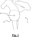
- Figure 1 shows a side schematic view of a scapula 1. Analysing the shape of the glenoid cavity of the scapula 1, it is possible to identify a circular area 2 in the lower part thereof, defined as glenoid "fossa" of the scapula and represented by the circumference 2.
- a glenoid positioning device allows precisely determining a centre 3 of the glenoid cavity 2, in particular in order to position a reference, for instance a Kirschner wire, which will be useful as a guide for the implantation of a glenoid part of a shoulder prosthesis, of the anatomic or of the reverse type.
- K-wires Kirschner wires
- Stepmann pins or other types of "pins”.
- Figure 2 shows a perspective view of an embodiment of a glenoid positioning device 100 according to the present invention.
- the representation of the glenoid positioning device 100 is presented as an "exploded" view, so as to more effectively display the elements, even the internal ones, of the glenoid positioning device 100.
- the glenoid positioning device 100 will be further represented and described even in an assembled form thereof.
- the glenoid positioning device 100 comprises a hub 101, with a reference through-hole 110 that will be described hereinafter, and comprising three housings 102a, 102b, and 102c radially arranged in the hub 101.
- the glenoid positioning device 100 then comprises three slide elements 103a, 103b and 103c, slidably housed within the three housings 102a, 102b, and 102c, respectively.
- the three slide elements 103a, 103b and 103c are configured to interact with a glenoid cavity, during the use of the glenoid positioning device 100.
- the glenoid positioning device 100 further comprises a central spindle 104 axially associated with the hub 101 and rotatable therein.
- the hub 101 further comprises a pin 105 configured to engage into a radial groove 107 of the hub 104, so as to allow a rotation of the central spindle 104 within the hub 101, but preventing a translation of the central spindle 104 in an axial direction.
- the glenoid positioning device 100 further comprises three connection bars 108a, 108b and 108c connecting each of the three slide elements 103a, 103b and 103c, respectively, with respective seats formed in the central spindle 104.
- the three slide elements 103a, 103b and 103c are thus configured to be radially extended or retracted, to identify a circular area of the glenoid cavity.
- the three slide elements 103a, 103b and 103c are thus configured to be radially extended or retracted by the action of the three connection bars 108a, 108b and 108c moved by a rotation of the central spindle 104.
- the rotation of the central spindle 104 is preferably performed, during the use, by means of a knob associable with the glenoid positioning device 100, not represented in the figures.
- Figure 3 shows a sectional side view of the glenoid positioning device 100, in the assembled form.
- a first slide element 103a and a second slide element 103b comprise respective protruding ends 109a and 109b configured to externally grasp a glenoid portion of a scapula.
- the protruding ends 109a and 109b comprise internal machined or knurled internal surfaces, configured to increase friction with a bone surface during the use of the glenoid positioning device 100, in the manner that will be described in the following.
- Figure 4 shows a perspective view of the glenoid positioning device 100, in an open configuration.
- first slide element 103a and the second slide element 103b are substantially opposite each other, i.e. aligned on opposite sides with respect to the hub 101 and to the central spindle 104.
- the third slide element 103c is substantially aligned in the transversal direction with respect to the first two slide elements 103a and 103b.
- the third slide element 103c is in particular configured to provide a visual reference by means of an own end: indeed for the scapular anatomy, it is not possible to provide for the third slide element 103c a protruding end similar to the protruding ends 109a and 109b.
- connection bars 108a, 108b and 108c are connected to the central spindle 104 and to the three slide elements 103a, 103b and 103c, respectively, by means of pins, so as to form a triple system of the rod-crank type.
- the triple system of the rod-crank type of the glenoid positioning device 100 is configured, during the rotation of the central spindle 104, to extend in a first phase the three slide elements 103a, 103b and 103 from a maximum closure position, represented in the subsequent figure 6 , up to a maximum opening position represented in figure 4 herein discussed.
- the three slide elements 103a, 103b and 103c are retracted in a further position, at least partially retracted, in which in use they interact with a scapular bone, as it will be described hereinafter.
- Figure 5 shows an upper view of the glenoid positioning device 100.
- the hub 101 and the central spindle 104 comprise respective reference through-holes 110 axially aligned to each other, which are configured for the axial insertion of a reference, for instance of a Kirschner wire.
- Figure 6 shows a perspective view of the glenoid positioning device 100, in a closed configuration.
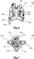
- Figure 7 shows an upper view of the glenoid positioning device 100.
- the slide elements 103a, 103b and 103c are configured to be extended or retracted, with the respective ends lying on a same circumference, which has a radius that is variable with the rotation of the central spindle 104.
- the hub 101 and the central spindle 104 comprise respective side access slots 111a and 111b to respective reference through-holes 110.
- Said side access slots 111a and 111b are aligned to each other, in particular for an angular position deriving from the rotation of the central spindle 104.
- Said angular position is preferably a complete closure position of the glenoid positioning device 100 as represented in figure 7 , so as to allow a side extraction of a reference such as for instance a Kirschner wire, inserted in the axial reference through-hole 110.
- a reference such as for instance a Kirschner wire
- Figure 8 shows a side schematic view of the scapula 1, in which the glenoid positioning device 100 is positioned in the use position.
- the three slide elements 103a, 103b and 103c are configured to identify a circular area 2 of the glenoid cavity, whereas the central spindle 104 and the related reference through-hole 110 are configured to identify a center 3 of the circular area 2, in particular for positioning a reference, for instance a Kirschner wire, in a center of the glenoid fossa of scapula.
- the glenoid positioning device 100 is positioned onto the lower part of the glenoid cavity.
- the slide elements 103a, 103b and 103c are radially extended until they pass the glenoid margin in the sagittal plane in the fore/aft direction.
- the slide elements 103a, 103b and 103c are radially retracted until they obtain the contact between the internal part of the ends 109a and 109b of the elements 103a and 103b and the glenoid margin, in the maximum width area of the latter on the sagittal plane in the fore/aft direction.
- the subsequent step provides to visually verify that the end of the slide element 103c is approximately located on the lowest point of the glenoid fossa of scapula; in this way the three points necessary to determine the circumference 2 that identifies the glenoid fossa of scapula have been identified.
- a reference in the example a Kirschner wire 4, is inserted into the central spindle 104 using a reference through-hole 110 present therein and within the hub 101.
- the point where the entry of the Kirschner wire 4 into the glenoid occurs represents the center 3 of the glenoid fossa of scapula of the scapula 1, treated with the above glenoid positioning device 100.
- the side access slots 11 1a and 111b both on the hub 101 and on the central spindle 104 are aligned to each other, and thus it is possible to remove the glenoid positioning device 100 from the reference, in this example from the Kirschner wire 4, provisionally implanted in the glenoid cavity, by passing the Kirschner wire 4 through the two aligned slots 111a and 111b.
- the radial stroke of the slide elements 103a, 103b and 103c is such as to pass, when they are radially extended, a glenoid margin in a sagittal plane in the fore/aft direction.
- Figure 9 shows a frontal schematic view of the scapula of figure 8 , in which a reference, for instance a Kirschner wire, is associated with the glenoid positioning device.
- a reference for instance a Kirschner wire
- the glenoid positioning device 100 is configured to identify a center of the glenoid fossa of scapula for the accurate and repeatable positioning of a reference, such as for instance the Kirschner wire 4.
- the glenoid positioning device 100 identifies the center 3 of the glenoid cavity with greater reliability, allowing a more accurate and repeatable positioning of a reference, constituted by a Kirschner wire 4, used during a shoulder prosthesis implantation.
- the slide elements 103a, 103b and 103c allow identifying a circular area of a glenoid cavity, and the central spindle 104 is configured to identify a center 3 of the circular area 2 for the positioning of a reference in a center of a glenoid fossa of scapula.
Landscapes
- Health & Medical Sciences (AREA)
- Life Sciences & Earth Sciences (AREA)
- Surgery (AREA)
- Orthopedic Medicine & Surgery (AREA)
- Medical Informatics (AREA)
- General Health & Medical Sciences (AREA)
- Biomedical Technology (AREA)
- Heart & Thoracic Surgery (AREA)
- Nuclear Medicine, Radiotherapy & Molecular Imaging (AREA)
- Molecular Biology (AREA)
- Animal Behavior & Ethology (AREA)
- Engineering & Computer Science (AREA)
- Public Health (AREA)
- Veterinary Medicine (AREA)
- Dentistry (AREA)
- Oral & Maxillofacial Surgery (AREA)
- Neurology (AREA)
- Prostheses (AREA)
- Surgical Instruments (AREA)
Description
- The present invention relates to a glenoid positioning device, in particular for positioning a reference into the glenoid cavity during a shoulder prosthesis implantation surgery.
- The invention finds particular utility in implantation surgery of a shoulder prosthesis, both anatomical and reverse; the following description is made with reference to this specific application field as exemplificatory disclosure.
- In general, the invention may be used to find a central positioning within a glenoid cavity of a scapula and to fix a reference there, such as for instance a Kirschner wire, which is usable for further operations during implantation of a shoulder prosthesis.
- In the shoulder prosthesis field, the use of prostheses is now widespread, typically modular prostheses constituted by a plurality of elements that can be combined with each other to obtain an anatomical or reverse prosthesis, and possibly to convert the prosthesis from anatomic to reverse.
- Some commonly used prostheses involve the use of a glenoid anchor inserted in a hole previously obtained substantially in the center of the glenoid cavity. In the event of an anatomical prosthesis, a polyethylene insert is typically fixed on the glenoid anchor, whereas in the event of a reverse prosthesis, a convex glenoid joint component, called glenosphere, is typically fixed on the glenoid anchor.
- A difficulty that arises is to accurately fix, in a central position in the glenoid cavity, the appropriate anchor so as to have the center of the prosthesis component coupled thereto aligned with the center of the glenoid cavity.
-
US2019/015116 discloses a patient specific solution for placing a glenoid implant according to the prior art. - In the prior art, there are in fact reproducibility problems of the optimal positioning in the center of the glenoid cavity, which can compromise the effectiveness of a shoulder prosthesis.
- An object of the present invention is to provide a glenoid positioning device having structural and functional characteristics such as to overcome the drawbacks complained of with reference to the prior art.
- A further object of the present invention is to allow the correct positioning of a reference, such as for example a Kirschner wire, which acts as a guide for an implantation of a glenoid part of a shoulder prosthesis, be it anatomical or reverse.
- A further object of the present invention is also to allow the correct positioning of a reference in the center of the glenoid fossa of scapula, for a better positioning of a shoulder prosthesis.
- The solution idea underlying the present invention is to make a mechanical guide that allows the approximation of a glenoid cavity by means of three circumferential points, meanwhile allowing the positioning of a reference in the center of the circumference thus identified, in particular for fixing a reference.
- Advantageously, the present invention allows a more reliable identification of the center of the glenoid cavity, allowing a more accurate and repeatable positioning of a reference, constituted for instance by a Kirschner wire, used during a shoulder prosthesis implantation.
- Based on this solution idea, there is provided a glenoid positioning device comprising: a hub with a reference through-hole and comprising three radially arranged housings; three slide elements slidably housed within said three housings, respectively, and configured to interact with a glenoid cavity; the three slide elements are configured to be radially extended or retracted to identify a circular area of a glenoid cavity.
- The slide elements are extended or retracted synchronously with each other. In this way, they may advantageously pass, when radially extended, a glenoid margin in a sagittal plane in the fore/aft direction, and thus provide a centering reference having a variable radius in a circumference thus identified, in particular for fixing a reference, for example for fixing a Kirschner wire.
- Preferably, the glenoid positioning device further comprises a central spindle axially associated with the hub and rotatable therein; and three connection bars connecting each slide element with the central spindle. The three slide elements are thus configured to be radially extended or retracted by the action of the three connection bars operated by a rotation of said central spindle.
- In this way, the three slide elements allow identifying a circular area of a glenoid cavity, and the central spindle is configured to identify a center of the circular area for positioning a reference in a center of a glenoid fossa of scapula. Thus, advantageously, it becomes possible to position a reference in the center of the fossa of scapula of a glenoid cavity in an accurate and repeatable manner.
- Preferably, two slide elements are substantially opposite each other and have protruding ends to externally grasp a glenoid portion of a scapula; preferably a third slide element that is transversal to the first two provides a visual reference to verify the alignment with an own circumference of the glenoid cavity.
- Preferably, the hub and the central spindle comprise respective through-holes that are axially aligned and configured for the axial insertion of a reference, for instance a Kirschner wire.
- Advantageously, the hub and the central spindle also comprise respective side access slots that are alignable to each other to allow a side extraction of the reference, for instance a Kirschner wire, i.e. a removal of the glenoid positioning device from the reference positioned in the glenoid area, once the reference has been correctly implanted. Advantageously, this allows decoupling the glenoid positioning device from the reference.
- Further characteristics and advantages of the invention will become clearer from the following detailed description, provided for illustrative and non-limiting purposes, and from the claims that are an integral part of the present description.
-
-
Figure 1 shows a side schematic view of a scapula, in which a glenoid cavity is visible; -
figure 2 shows an exploded perspective view of an embodiment of a glenoid positioning device according to the present invention; -
figure 3 shows a sectional side view of an embodiment of a glenoid positioning device according to the present invention, in the assembled form; -
figure 4 shows a perspective view of an embodiment of a glenoid positioning device according to the present invention, in an open configuration; -
figure 5 shows an upper view of the glenoid positioning device offigure 4 ; -
figure 6 shows a perspective view of an embodiment of a glenoid positioning device of the present invention, in a closed configuration; -
figure 7 shows an upper view of the glenoid positioning device offigure 6 ; -
figure 8 shows a side schematic view of a scapula, in which a glenoid positioning device according to the present invention is positioned; -
figure 9 shows a frontal schematic view of the scapula offigure 8 , in which a Kirschner wire is associated with the glenoid positioning device. - In different figures, analogous elements will be indicated by analogous reference numbers.
-
Figure 1 shows a side schematic view of ascapula 1. Analysing the shape of the glenoid cavity of thescapula 1, it is possible to identify acircular area 2 in the lower part thereof, defined as glenoid "fossa" of the scapula and represented by thecircumference 2. - As it will be clear hereinafter, a glenoid positioning device according to the present invention allows precisely determining a
centre 3 of theglenoid cavity 2, in particular in order to position a reference, for instance a Kirschner wire, which will be useful as a guide for the implantation of a glenoid part of a shoulder prosthesis, of the anatomic or of the reverse type. - Usable references for implantation in the
glenoid cavity 2, in cooperation with the glenoid positioning device of the present invention include, not limited to: Kirschner wires ("K-wires") or "Steinmann pins" or other types of "pins". -
Figure 2 shows a perspective view of an embodiment of aglenoid positioning device 100 according to the present invention. The representation of theglenoid positioning device 100 is presented as an "exploded" view, so as to more effectively display the elements, even the internal ones, of theglenoid positioning device 100. Theglenoid positioning device 100 will be further represented and described even in an assembled form thereof. - The
glenoid positioning device 100 comprises ahub 101, with a reference through-hole 110 that will be described hereinafter, and comprising threehousings hub 101. - The
glenoid positioning device 100 then comprises threeslide elements housings - As it will become clearer hereinafter, the three
slide elements glenoid positioning device 100. - The
glenoid positioning device 100 further comprises acentral spindle 104 axially associated with thehub 101 and rotatable therein. Preferably, thehub 101 further comprises apin 105 configured to engage into aradial groove 107 of thehub 104, so as to allow a rotation of thecentral spindle 104 within thehub 101, but preventing a translation of thecentral spindle 104 in an axial direction. - The
glenoid positioning device 100 further comprises threeconnection bars slide elements central spindle 104. - In the
glenoid positioning device 100, the threeslide elements - In particular, the three
slide elements connection bars central spindle 104. - The rotation of the
central spindle 104 is preferably performed, during the use, by means of a knob associable with theglenoid positioning device 100, not represented in the figures. -
Figure 3 shows a sectional side view of theglenoid positioning device 100, in the assembled form. - In this side view it is possible to observe that a
first slide element 103a and asecond slide element 103b compriserespective protruding ends protruding ends glenoid positioning device 100, in the manner that will be described in the following. -
Figure 4 shows a perspective view of theglenoid positioning device 100, in an open configuration. - As visible in this figure, the
first slide element 103a and thesecond slide element 103b are substantially opposite each other, i.e. aligned on opposite sides with respect to thehub 101 and to thecentral spindle 104. - The
third slide element 103c is substantially aligned in the transversal direction with respect to the first twoslide elements third slide element 103c is in particular configured to provide a visual reference by means of an own end: indeed for the scapular anatomy, it is not possible to provide for thethird slide element 103c a protruding end similar to theprotruding ends - In this view it is possible to view that the three
connection bars central spindle 104 and to the threeslide elements - In particular, the triple system of the rod-crank type of the
glenoid positioning device 100 is configured, during the rotation of thecentral spindle 104, to extend in a first phase the threeslide elements figure 6 , up to a maximum opening position represented infigure 4 herein discussed. - Furthermore, during a rotation of the
central spindle 104 in the opposite direction, the threeslide elements -
Figure 5 shows an upper view of theglenoid positioning device 100. - In this view it is possible to observe that the
hub 101 and thecentral spindle 104 comprise respective reference through-holes 110 axially aligned to each other, which are configured for the axial insertion of a reference, for instance of a Kirschner wire. -
Figure 6 shows a perspective view of theglenoid positioning device 100, in a closed configuration. - Comparing the view of
figure 6 with the view offigure 4 , it is possible to observe that in theglenoid positioning device 100 theslide elements -
Figure 7 shows an upper view of theglenoid positioning device 100. - Still comparing the view of
figure 5 with the view offigure 7 , it is possible to observe that in theglenoid positioning device 100 theslide elements central spindle 104. - Furthermore, it is possible to view that the
hub 101 and thecentral spindle 104 comprise respectiveside access slots holes 110. - Said
side access slots central spindle 104. - Said angular position is preferably a complete closure position of the
glenoid positioning device 100 as represented infigure 7 , so as to allow a side extraction of a reference such as for instance a Kirschner wire, inserted in the axial reference through-hole 110. - In this way, it is possible to easily remove the
glenoid positioning device 100 by means of a side movement, once the reference has been positioned and implanted in the center of the glenoid fossa of scapula. -
Figure 8 shows a side schematic view of thescapula 1, in which theglenoid positioning device 100 is positioned in the use position. - According to what has already been described, in the
glenoid positioning device 100 the threeslide elements circular area 2 of the glenoid cavity, whereas thecentral spindle 104 and the related reference through-hole 110 are configured to identify acenter 3 of thecircular area 2, in particular for positioning a reference, for instance a Kirschner wire, in a center of the glenoid fossa of scapula. - For illustrative and non-limiting purposes, an example of use of the
glenoid positioning device 100 according to the present invention is now provided. - First of all, the
glenoid positioning device 100 is positioned onto the lower part of the glenoid cavity. - Afterwards, through the rotation of the
central spindle 104, theslide elements - Subsequently, still rotating the
central spindle 104, theslide elements ends elements - The subsequent step provides to visually verify that the end of the
slide element 103c is approximately located on the lowest point of the glenoid fossa of scapula; in this way the three points necessary to determine thecircumference 2 that identifies the glenoid fossa of scapula have been identified. - Thus a reference, in the example a
Kirschner wire 4, is inserted into thecentral spindle 104 using a reference through-hole 110 present therein and within thehub 101. - Advantageously, the point where the entry of the
Kirschner wire 4 into the glenoid occurs, represents thecenter 3 of the glenoid fossa of scapula of thescapula 1, treated with the aboveglenoid positioning device 100. - Once the complete closure of the device has been obtained by means of the further rotation of the
central spindle 104, the side access slots 11 1a and 111b both on thehub 101 and on thecentral spindle 104 are aligned to each other, and thus it is possible to remove theglenoid positioning device 100 from the reference, in this example from theKirschner wire 4, provisionally implanted in the glenoid cavity, by passing theKirschner wire 4 through the two alignedslots - Therefore, the radial stroke of the
slide elements -
Figure 9 shows a frontal schematic view of the scapula offigure 8 , in which a reference, for instance a Kirschner wire, is associated with the glenoid positioning device. - According to what has been already described, the
glenoid positioning device 100 is configured to identify a center of the glenoid fossa of scapula for the accurate and repeatable positioning of a reference, such as for instance theKirschner wire 4. - With the solution of the present invention it is provided that the
glenoid positioning device 100 identifies thecenter 3 of the glenoid cavity with greater reliability, allowing a more accurate and repeatable positioning of a reference, constituted by aKirschner wire 4, used during a shoulder prosthesis implantation. - The
slide elements central spindle 104 is configured to identify acenter 3 of thecircular area 2 for the positioning of a reference in a center of a glenoid fossa of scapula. - Thus, advantageously, it is possible to position a reference in the center of the fossa of scapula of a glenoid cavity in an accurate and repeatable manner.
- It is clear that, in order to meet contingent needs, further implementations and modifications of the present invention will be possible for the skilled in the art. The above described embodiment is thus to be intended as provided for illustrative and not limitative purposes. The scope of the application is defined by the appended claims.
Claims (14)
- Glenoid positioning device (100) comprising:- a hub (101) with a reference through-hole (110) and comprising three housings (102a, 102b, 102c) arranged radially;- three slide elements (103a, 103b, 103c) slidably housed within said three housings (102a, 102b, 102c) respectively, said three slide elements (103a, 103b, 103c) being configured to interact with a glenoid cavity;wherein said three slide elements (103a, 103b, 103c) are configured to be radially extended or retracted to identify a circular area (2) of a glenoid cavity.
- Glenoid positioning device (100) according to claim 1, further comprising:- a central spindle (104) axially associated with said hub (101) and rotatable therein;- three connection bars (108a, 108b, 108c) connecting each of said three slide elements (103a, 103b, 103c) with said central spindle (104), respectively;wherein said three slide elements (103a, 103b, 103c) are configured to be radially extended or retracted by the action of said three connection bars (108a, 108b, 108c) operated by a rotation of said central spindle (104).
- Glenoid positioning device according to claim 2, wherein a first slide element (103a) and a second slide element (103b) of said three slide elements (103a, 103b, 103c) are substantially opposite each other, and wherein said first slide element (103a) and said second slide element (103b) comprise respective protruding ends (109a, 109b) configured to externally grasp a glenoid portion of a scapula.
- Glenoid positioning device according to claim 3, wherein a third slide element (103c) of said three slide elements (103a, 103b, 103c) is aligned substantially transversally to said first slide element (103a) and to said second slide element (103b), said third slide element (103c) being configured to provide a visual reference at its own end.
- Glenoid positioning device according to claim 3 or 4, wherein said protruding ends (109a, 109b) comprise internal surfaces that are machined so as to increase friction with a bone surface.
- Glenoid positioning device according to any one of claims 2 to 5, wherein said hub (101) and said central spindle (104) comprise respective reference through-holes (110) that are axially aligned and configured for the axial insertion of a reference (4).
- Glenoid positioning device according to claim 6, wherein said hub (101) and said central spindle (104) comprise respective side access slots (111a, 111b) to said respective reference through-holes (110), said side access slots (111a, 111b) being aligned to each other for an angular position of said rotation of said central spindle (104), preferably in a position of complete closure, to allow the removal of said glenoid positioning device from said reference (4) positioned in the glenoid cavity.
- Glenoid positioning device according to any one of claims 2 to 7, wherein said slide elements (103a, 103b, 103c) are configured to be extended or retracted with respective ends lying on a same circumference, said circumference having a radius that is variable with said rotation of said central spindle (104).
- Glenoid positioning device according to any one of claims 2 to 8, wherein said three connection bars (108a, 108b, 108c) are connected to said central spindle (104) and to said three slide elements (103a, 103b, 103c), respectively, by means of pins, thus providing a triple rod-crank type system.
- Glenoid positioning device according to claim 9, wherein said triple rod-crank type system is configured, during said rotation of said central spindle (104), to extend said three slide elements (103a, 103b, 103c) from a position of maximum closure to a position of maximum opening and, during said rotation of said central spindle (104) in an opposite direction, to retract said three slide elements (103a, 103b, 103c) in a further position that is at least partially retracted.
- Glenoid positioning device according to any one of claims 1 to 10, wherein the stroke of said three slide elements (103a, 103b, 103c), when radially extended, is such as to pass a glenoid margin in a sagittal plane in the fore/aft direction.
- Glenoid positioning device according to any one of claims 2 to 11, wherein said hub (101) further comprises a pin (105) configured to engage into a radial groove (107) of said central spindle (104), to allow said rotation of said central spindle (104), thus preventing a translation of said central spindle (104) in an axial direction.
- Glenoid positioning device according to any one of claims 2 to 12, wherein said central spindle (104) is configured to identify a center (3) of a circular area (2) of a glenoid cavity for positioning a reference (4) in a center (3) of a glenoid fossa of scapula.
- Glenoid positioning device according to claim 13, wherein said reference (4) is a K-wire.
Applications Claiming Priority (2)
| Application Number | Priority Date | Filing Date | Title |
|---|---|---|---|
| IT102019000024069A IT201900024069A1 (en) | 2019-12-16 | 2019-12-16 | Glenoid positioning device |
| PCT/EP2020/085554 WO2021122317A1 (en) | 2019-12-16 | 2020-12-10 | Glenoid positioning device |
Publications (2)
| Publication Number | Publication Date |
|---|---|
| EP4076235A1 EP4076235A1 (en) | 2022-10-26 |
| EP4076235B1 true EP4076235B1 (en) | 2023-11-01 |
Family
ID=70155062
Family Applications (1)
| Application Number | Title | Priority Date | Filing Date |
|---|---|---|---|
| EP20820434.7A Active EP4076235B1 (en) | 2019-12-16 | 2020-12-10 | Glenoid positioning device |
Country Status (9)
| Country | Link |
|---|---|
| US (1) | US12150658B2 (en) |
| EP (1) | EP4076235B1 (en) |
| JP (1) | JP7611920B2 (en) |
| CN (1) | CN114901178A (en) |
| AU (1) | AU2020406512B2 (en) |
| BR (1) | BR112022011820A2 (en) |
| ES (1) | ES2966375T3 (en) |
| IT (1) | IT201900024069A1 (en) |
| WO (1) | WO2021122317A1 (en) |
Family Cites Families (31)
| Publication number | Priority date | Publication date | Assignee | Title |
|---|---|---|---|---|
| US2148692A (en) * | 1938-08-30 | 1939-02-28 | Guinn James Weldon | Articulator |
| US5540697A (en) * | 1993-02-12 | 1996-07-30 | U.S. Medical Products, Inc. | Prosthetic socket installation apparatus and method |
| GB9926564D0 (en) * | 1999-11-10 | 2000-01-12 | Depuy Int Ltd | Bone resection device |
| US7879042B2 (en) * | 2004-03-05 | 2011-02-01 | Depuy Products, Inc. | Surface replacement extractor device and associated method |
| US8535329B2 (en) * | 2004-10-29 | 2013-09-17 | Kinamed, Inc. | Tracking tools and method for computer-assisted shoulder replacement surgery |
| US7744602B2 (en) | 2005-01-28 | 2010-06-29 | Steven M. Teeny | Acetabular shell removal tool |
| WO2006097932A2 (en) * | 2005-03-17 | 2006-09-21 | Active Implants Corporation | Implant devices |
| US8114087B2 (en) * | 2008-04-04 | 2012-02-14 | Depuy Products, Inc. | Humeral rotating burr guide |
| FR2945436A1 (en) * | 2009-05-14 | 2010-11-19 | Tornier Sa | SURGICAL INSTRUMENTATION OF BONE DISTRACTION OF THE SHOULDER |
| US8702717B2 (en) * | 2009-07-31 | 2014-04-22 | Zimmer Gmbh | Glenoid alignment tool |
| GB201003921D0 (en) | 2010-03-10 | 2010-04-21 | Depuy Orthopaedie Gmbh | Orthopaedic instrument |
| JP5911474B2 (en) * | 2010-04-30 | 2016-04-27 | スミス アンド ネフュー インコーポレーテッドSmith & Nephew,Inc. | Guide for drilling holes in irregularly shaped bodies |
| CA2816337C (en) * | 2010-10-29 | 2019-10-22 | The Cleveland Clinic Foundation | System and method for association of a guiding aid with a patient tissue |
| US9226830B2 (en) * | 2011-03-18 | 2016-01-05 | DePuy Synthes Products, Inc. | Device and method for retroversion correction for shoulder arthroplasty |
| US9408613B2 (en) * | 2011-12-13 | 2016-08-09 | Biomet Manufacturing, Llc | Glenoid reamer |
| US10034777B2 (en) * | 2012-03-30 | 2018-07-31 | DePuy Synthes Products, Inc. | Implant insertion tool for use in a surgical procedure to implant a stemless humeral component |
| AU2014228420B2 (en) | 2013-03-15 | 2018-11-08 | Smith & Nephew, Inc. | Surgical fastening |
| EP3628245B1 (en) * | 2013-10-10 | 2025-01-29 | Stryker European Operations Limited | Method for designing and producing a shoulder surgery guide |
| EP3068317B1 (en) * | 2013-11-13 | 2018-08-22 | Tornier | Shoulder patient specific instrument |
| GB201320745D0 (en) * | 2013-11-25 | 2014-01-08 | Darwood Alastair | A method and apparatus for the intraoperative production of a surgical guide |
| US10813774B2 (en) * | 2014-03-07 | 2020-10-27 | Biomet Manufacturing, Llc | Subject contacting plate |
| US11026810B2 (en) * | 2014-03-07 | 2021-06-08 | Biomet Manufacturing, Llc | Prosthesis alignment system |
| US10952872B2 (en) * | 2014-06-12 | 2021-03-23 | Limacorporate S.P.A. | Instrument for the removal of a bone insert and corresponding method |
| CA2979426A1 (en) * | 2015-03-25 | 2016-09-29 | Orthosoft Ulc | Glenosphere-implant positioning device and method |
| GB201514727D0 (en) * | 2015-08-19 | 2015-09-30 | Depuy Ireland | An Assembly Tool |
| US10631880B1 (en) * | 2015-12-01 | 2020-04-28 | Innovative Medical Solutions LLC | Cannulated modular magnetic glenoid reamer |
| US11234721B2 (en) * | 2017-07-11 | 2022-02-01 | Howmedica Osteonics Corp. | Guides and instruments for improving accuracy of glenoid implant placement |
| EP3833277A1 (en) * | 2018-08-10 | 2021-06-16 | Tornier, Inc. | Guides and instruments for improving accuracy of glenoid implant placement |
| US11123086B1 (en) * | 2019-01-04 | 2021-09-21 | Innovative Medical Solutions LLC | Cannulated modular magnetic glenoid reamer |
| US11986401B2 (en) * | 2019-08-13 | 2024-05-21 | Howmedica Osteonics Corp. | Shoulder implant impactor with stabilization features |
| FR3104403B1 (en) * | 2019-12-11 | 2021-12-10 | Fournitures Hospitalieres Ind | Guiding device for guiding the implantation of a guide pin in a glenoid of a scapula |
-
2019
- 2019-12-16 IT IT102019000024069A patent/IT201900024069A1/en unknown
-
2020
- 2020-12-10 US US17/785,752 patent/US12150658B2/en active Active
- 2020-12-10 WO PCT/EP2020/085554 patent/WO2021122317A1/en not_active Ceased
- 2020-12-10 BR BR112022011820A patent/BR112022011820A2/en not_active Application Discontinuation
- 2020-12-10 EP EP20820434.7A patent/EP4076235B1/en active Active
- 2020-12-10 CN CN202080087143.4A patent/CN114901178A/en active Pending
- 2020-12-10 ES ES20820434T patent/ES2966375T3/en active Active
- 2020-12-10 AU AU2020406512A patent/AU2020406512B2/en active Active
- 2020-12-10 JP JP2022536901A patent/JP7611920B2/en active Active
Also Published As
| Publication number | Publication date |
|---|---|
| AU2020406512B2 (en) | 2026-03-19 |
| WO2021122317A1 (en) | 2021-06-24 |
| EP4076235A1 (en) | 2022-10-26 |
| ES2966375T3 (en) | 2024-04-22 |
| JP2023507361A (en) | 2023-02-22 |
| BR112022011820A2 (en) | 2022-08-30 |
| CN114901178A (en) | 2022-08-12 |
| AU2020406512A1 (en) | 2022-06-02 |
| US20230064917A1 (en) | 2023-03-02 |
| US12150658B2 (en) | 2024-11-26 |
| JP7611920B2 (en) | 2025-01-10 |
| IT201900024069A1 (en) | 2021-06-16 |
Similar Documents
| Publication | Publication Date | Title |
|---|---|---|
| US12279962B2 (en) | Glenoid implant | |
| EP3856082B1 (en) | Improved glenoid adapter for shoulder joint prosthesis | |
| US11311301B2 (en) | Flexible bone reamer | |
| US7611539B2 (en) | Shoulder prosthesis assembly | |
| US7699853B2 (en) | Method and instruments for positioning humeral component during shoulder arthroplasty | |
| US8968409B2 (en) | Orthopaedic implant and method of installing same | |
| US12458373B2 (en) | Bone reamer and methods of use | |
| US20210338444A1 (en) | Methods and apparatuses for trialing a humeral head | |
| US20060149249A1 (en) | Osteosynthesis plate for the osteosynthesis of small neighbouring bones | |
| CN113507903B (en) | Acetabular devices for hip revision surgery | |
| AU2020406512B2 (en) | Glenoid positioning device | |
| CA3136945A1 (en) | Hip arthroplasty trial systems and associated medical devices, methods, and kits | |
| EP4274497A2 (en) | Locking trocar and method of using the same | |
| WO2001028467A1 (en) | Tibial trial system |
Legal Events
| Date | Code | Title | Description |
|---|---|---|---|
| STAA | Information on the status of an ep patent application or granted ep patent |
Free format text: STATUS: UNKNOWN |
|
| STAA | Information on the status of an ep patent application or granted ep patent |
Free format text: STATUS: THE INTERNATIONAL PUBLICATION HAS BEEN MADE |
|
| PUAI | Public reference made under article 153(3) epc to a published international application that has entered the european phase |
Free format text: ORIGINAL CODE: 0009012 |
|
| STAA | Information on the status of an ep patent application or granted ep patent |
Free format text: STATUS: REQUEST FOR EXAMINATION WAS MADE |
|
| 17P | Request for examination filed |
Effective date: 20220623 |
|
| AK | Designated contracting states |
Kind code of ref document: A1 Designated state(s): AL AT BE BG CH CY CZ DE DK EE ES FI FR GB GR HR HU IE IS IT LI LT LU LV MC MK MT NL NO PL PT RO RS SE SI SK SM TR |
|
| DAV | Request for validation of the european patent (deleted) | ||
| DAX | Request for extension of the european patent (deleted) | ||
| REG | Reference to a national code |
Ref country code: DE Ref legal event code: R079 Free format text: PREVIOUS MAIN CLASS: A61B0017840000 Ipc: A61B0017900000 Ref country code: DE Ref legal event code: R079 Ref document number: 602020020437 Country of ref document: DE Free format text: PREVIOUS MAIN CLASS: A61B0017840000 Ipc: A61B0017900000 |
|
| GRAP | Despatch of communication of intention to grant a patent |
Free format text: ORIGINAL CODE: EPIDOSNIGR1 |
|
| STAA | Information on the status of an ep patent application or granted ep patent |
Free format text: STATUS: GRANT OF PATENT IS INTENDED |
|
| RIC1 | Information provided on ipc code assigned before grant |
Ipc: A61F 2/40 20060101ALI20230427BHEP Ipc: A61B 17/84 20060101ALI20230427BHEP Ipc: A61B 17/17 20060101ALI20230427BHEP Ipc: A61B 17/90 20060101AFI20230427BHEP |
|
| INTG | Intention to grant announced |
Effective date: 20230523 |
|
| RAP3 | Party data changed (applicant data changed or rights of an application transferred) |
Owner name: LIMACORPORATE S.P.A. |
|
| P01 | Opt-out of the competence of the unified patent court (upc) registered |
Effective date: 20230520 |
|
| GRAS | Grant fee paid |
Free format text: ORIGINAL CODE: EPIDOSNIGR3 |
|
| GRAA | (expected) grant |
Free format text: ORIGINAL CODE: 0009210 |
|
| STAA | Information on the status of an ep patent application or granted ep patent |
Free format text: STATUS: THE PATENT HAS BEEN GRANTED |
|
| AK | Designated contracting states |
Kind code of ref document: B1 Designated state(s): AL AT BE BG CH CY CZ DE DK EE ES FI FR GB GR HR HU IE IS IT LI LT LU LV MC MK MT NL NO PL PT RO RS SE SI SK SM TR |
|
| REG | Reference to a national code |
Ref country code: GB Ref legal event code: FG4D |
|
| REG | Reference to a national code |
Ref country code: CH Ref legal event code: EP |
|
| REG | Reference to a national code |
Ref country code: DE Ref legal event code: R096 Ref document number: 602020020437 Country of ref document: DE |
|
| REG | Reference to a national code |
Ref country code: IE Ref legal event code: FG4D |
|
| REG | Reference to a national code |
Ref country code: LT Ref legal event code: MG9D |
|
| REG | Reference to a national code |
Ref country code: NL Ref legal event code: MP Effective date: 20231101 |
|
| PG25 | Lapsed in a contracting state [announced via postgrant information from national office to epo] |
Ref country code: GR Free format text: LAPSE BECAUSE OF FAILURE TO SUBMIT A TRANSLATION OF THE DESCRIPTION OR TO PAY THE FEE WITHIN THE PRESCRIBED TIME-LIMIT Effective date: 20240202 |
|
| PG25 | Lapsed in a contracting state [announced via postgrant information from national office to epo] |
Ref country code: IS Free format text: LAPSE BECAUSE OF FAILURE TO SUBMIT A TRANSLATION OF THE DESCRIPTION OR TO PAY THE FEE WITHIN THE PRESCRIBED TIME-LIMIT Effective date: 20240301 |
|
| PG25 | Lapsed in a contracting state [announced via postgrant information from national office to epo] |
Ref country code: LT Free format text: LAPSE BECAUSE OF FAILURE TO SUBMIT A TRANSLATION OF THE DESCRIPTION OR TO PAY THE FEE WITHIN THE PRESCRIBED TIME-LIMIT Effective date: 20231101 |
|
| REG | Reference to a national code |
Ref country code: AT Ref legal event code: MK05 Ref document number: 1626324 Country of ref document: AT Kind code of ref document: T Effective date: 20231101 |
|
| PG25 | Lapsed in a contracting state [announced via postgrant information from national office to epo] |
Ref country code: NL Free format text: LAPSE BECAUSE OF FAILURE TO SUBMIT A TRANSLATION OF THE DESCRIPTION OR TO PAY THE FEE WITHIN THE PRESCRIBED TIME-LIMIT Effective date: 20231101 |
|
| REG | Reference to a national code |
Ref country code: ES Ref legal event code: FG2A Ref document number: 2966375 Country of ref document: ES Kind code of ref document: T3 Effective date: 20240422 |
|
| PG25 | Lapsed in a contracting state [announced via postgrant information from national office to epo] |
Ref country code: AT Free format text: LAPSE BECAUSE OF FAILURE TO SUBMIT A TRANSLATION OF THE DESCRIPTION OR TO PAY THE FEE WITHIN THE PRESCRIBED TIME-LIMIT Effective date: 20231101 |
|
| PG25 | Lapsed in a contracting state [announced via postgrant information from national office to epo] |
Ref country code: NL Free format text: LAPSE BECAUSE OF FAILURE TO SUBMIT A TRANSLATION OF THE DESCRIPTION OR TO PAY THE FEE WITHIN THE PRESCRIBED TIME-LIMIT Effective date: 20231101 Ref country code: LT Free format text: LAPSE BECAUSE OF FAILURE TO SUBMIT A TRANSLATION OF THE DESCRIPTION OR TO PAY THE FEE WITHIN THE PRESCRIBED TIME-LIMIT Effective date: 20231101 Ref country code: IS Free format text: LAPSE BECAUSE OF FAILURE TO SUBMIT A TRANSLATION OF THE DESCRIPTION OR TO PAY THE FEE WITHIN THE PRESCRIBED TIME-LIMIT Effective date: 20240301 Ref country code: GR Free format text: LAPSE BECAUSE OF FAILURE TO SUBMIT A TRANSLATION OF THE DESCRIPTION OR TO PAY THE FEE WITHIN THE PRESCRIBED TIME-LIMIT Effective date: 20240202 Ref country code: BG Free format text: LAPSE BECAUSE OF FAILURE TO SUBMIT A TRANSLATION OF THE DESCRIPTION OR TO PAY THE FEE WITHIN THE PRESCRIBED TIME-LIMIT Effective date: 20240201 Ref country code: AT Free format text: LAPSE BECAUSE OF FAILURE TO SUBMIT A TRANSLATION OF THE DESCRIPTION OR TO PAY THE FEE WITHIN THE PRESCRIBED TIME-LIMIT Effective date: 20231101 Ref country code: PT Free format text: LAPSE BECAUSE OF FAILURE TO SUBMIT A TRANSLATION OF THE DESCRIPTION OR TO PAY THE FEE WITHIN THE PRESCRIBED TIME-LIMIT Effective date: 20240301 |
|
| PG25 | Lapsed in a contracting state [announced via postgrant information from national office to epo] |
Ref country code: SE Free format text: LAPSE BECAUSE OF FAILURE TO SUBMIT A TRANSLATION OF THE DESCRIPTION OR TO PAY THE FEE WITHIN THE PRESCRIBED TIME-LIMIT Effective date: 20231101 Ref country code: RS Free format text: LAPSE BECAUSE OF FAILURE TO SUBMIT A TRANSLATION OF THE DESCRIPTION OR TO PAY THE FEE WITHIN THE PRESCRIBED TIME-LIMIT Effective date: 20231101 Ref country code: PL Free format text: LAPSE BECAUSE OF FAILURE TO SUBMIT A TRANSLATION OF THE DESCRIPTION OR TO PAY THE FEE WITHIN THE PRESCRIBED TIME-LIMIT Effective date: 20231101 Ref country code: NO Free format text: LAPSE BECAUSE OF FAILURE TO SUBMIT A TRANSLATION OF THE DESCRIPTION OR TO PAY THE FEE WITHIN THE PRESCRIBED TIME-LIMIT Effective date: 20240201 Ref country code: LV Free format text: LAPSE BECAUSE OF FAILURE TO SUBMIT A TRANSLATION OF THE DESCRIPTION OR TO PAY THE FEE WITHIN THE PRESCRIBED TIME-LIMIT Effective date: 20231101 Ref country code: HR Free format text: LAPSE BECAUSE OF FAILURE TO SUBMIT A TRANSLATION OF THE DESCRIPTION OR TO PAY THE FEE WITHIN THE PRESCRIBED TIME-LIMIT Effective date: 20231101 |
|
| PG25 | Lapsed in a contracting state [announced via postgrant information from national office to epo] |
Ref country code: DK Free format text: LAPSE BECAUSE OF FAILURE TO SUBMIT A TRANSLATION OF THE DESCRIPTION OR TO PAY THE FEE WITHIN THE PRESCRIBED TIME-LIMIT Effective date: 20231101 |
|
| PG25 | Lapsed in a contracting state [announced via postgrant information from national office to epo] |
Ref country code: CZ Free format text: LAPSE BECAUSE OF FAILURE TO SUBMIT A TRANSLATION OF THE DESCRIPTION OR TO PAY THE FEE WITHIN THE PRESCRIBED TIME-LIMIT Effective date: 20231101 |
|
| PG25 | Lapsed in a contracting state [announced via postgrant information from national office to epo] |
Ref country code: SK Free format text: LAPSE BECAUSE OF FAILURE TO SUBMIT A TRANSLATION OF THE DESCRIPTION OR TO PAY THE FEE WITHIN THE PRESCRIBED TIME-LIMIT Effective date: 20231101 |
|
| PG25 | Lapsed in a contracting state [announced via postgrant information from national office to epo] |
Ref country code: SM Free format text: LAPSE BECAUSE OF FAILURE TO SUBMIT A TRANSLATION OF THE DESCRIPTION OR TO PAY THE FEE WITHIN THE PRESCRIBED TIME-LIMIT Effective date: 20231101 Ref country code: SK Free format text: LAPSE BECAUSE OF FAILURE TO SUBMIT A TRANSLATION OF THE DESCRIPTION OR TO PAY THE FEE WITHIN THE PRESCRIBED TIME-LIMIT Effective date: 20231101 Ref country code: IT Free format text: LAPSE BECAUSE OF NON-PAYMENT OF DUE FEES Effective date: 20231210 Ref country code: EE Free format text: LAPSE BECAUSE OF FAILURE TO SUBMIT A TRANSLATION OF THE DESCRIPTION OR TO PAY THE FEE WITHIN THE PRESCRIBED TIME-LIMIT Effective date: 20231101 Ref country code: DK Free format text: LAPSE BECAUSE OF FAILURE TO SUBMIT A TRANSLATION OF THE DESCRIPTION OR TO PAY THE FEE WITHIN THE PRESCRIBED TIME-LIMIT Effective date: 20231101 Ref country code: CZ Free format text: LAPSE BECAUSE OF FAILURE TO SUBMIT A TRANSLATION OF THE DESCRIPTION OR TO PAY THE FEE WITHIN THE PRESCRIBED TIME-LIMIT Effective date: 20231101 |
|
| REG | Reference to a national code |
Ref country code: DE Ref legal event code: R097 Ref document number: 602020020437 Country of ref document: DE |
|
| PG25 | Lapsed in a contracting state [announced via postgrant information from national office to epo] |
Ref country code: LU Free format text: LAPSE BECAUSE OF NON-PAYMENT OF DUE FEES Effective date: 20231210 |
|
| PG25 | Lapsed in a contracting state [announced via postgrant information from national office to epo] |
Ref country code: MC Free format text: LAPSE BECAUSE OF FAILURE TO SUBMIT A TRANSLATION OF THE DESCRIPTION OR TO PAY THE FEE WITHIN THE PRESCRIBED TIME-LIMIT Effective date: 20231101 |
|
| PG25 | Lapsed in a contracting state [announced via postgrant information from national office to epo] |
Ref country code: MC Free format text: LAPSE BECAUSE OF FAILURE TO SUBMIT A TRANSLATION OF THE DESCRIPTION OR TO PAY THE FEE WITHIN THE PRESCRIBED TIME-LIMIT Effective date: 20231101 Ref country code: LU Free format text: LAPSE BECAUSE OF NON-PAYMENT OF DUE FEES Effective date: 20231210 |
|
| PLBE | No opposition filed within time limit |
Free format text: ORIGINAL CODE: 0009261 |
|
| STAA | Information on the status of an ep patent application or granted ep patent |
Free format text: STATUS: NO OPPOSITION FILED WITHIN TIME LIMIT |
|
| 26N | No opposition filed |
Effective date: 20240802 |
|
| PG25 | Lapsed in a contracting state [announced via postgrant information from national office to epo] |
Ref country code: SI Free format text: LAPSE BECAUSE OF FAILURE TO SUBMIT A TRANSLATION OF THE DESCRIPTION OR TO PAY THE FEE WITHIN THE PRESCRIBED TIME-LIMIT Effective date: 20231101 |
|
| PG25 | Lapsed in a contracting state [announced via postgrant information from national office to epo] |
Ref country code: SI Free format text: LAPSE BECAUSE OF FAILURE TO SUBMIT A TRANSLATION OF THE DESCRIPTION OR TO PAY THE FEE WITHIN THE PRESCRIBED TIME-LIMIT Effective date: 20231101 |
|
| PG25 | Lapsed in a contracting state [announced via postgrant information from national office to epo] |
Ref country code: IT Free format text: LAPSE BECAUSE OF NON-PAYMENT OF DUE FEES Effective date: 20231210 |
|
| PGRI | Patent reinstated in contracting state [announced from national office to epo] |
Ref country code: IT Effective date: 20240102 |
|
| PG25 | Lapsed in a contracting state [announced via postgrant information from national office to epo] |
Ref country code: IT Free format text: LAPSE BECAUSE OF NON-PAYMENT OF DUE FEES Effective date: 20231210 |
|
| PGRI | Patent reinstated in contracting state [announced from national office to epo] |
Ref country code: IT Effective date: 20240102 |
|
| PG25 | Lapsed in a contracting state [announced via postgrant information from national office to epo] |
Ref country code: RO Free format text: LAPSE BECAUSE OF FAILURE TO SUBMIT A TRANSLATION OF THE DESCRIPTION OR TO PAY THE FEE WITHIN THE PRESCRIBED TIME-LIMIT Effective date: 20231101 |
|
| PG25 | Lapsed in a contracting state [announced via postgrant information from national office to epo] |
Ref country code: FI Free format text: LAPSE BECAUSE OF FAILURE TO SUBMIT A TRANSLATION OF THE DESCRIPTION OR TO PAY THE FEE WITHIN THE PRESCRIBED TIME-LIMIT Effective date: 20231101 |
|
| PG25 | Lapsed in a contracting state [announced via postgrant information from national office to epo] |
Ref country code: CY Free format text: LAPSE BECAUSE OF FAILURE TO SUBMIT A TRANSLATION OF THE DESCRIPTION OR TO PAY THE FEE WITHIN THE PRESCRIBED TIME-LIMIT; INVALID AB INITIO Effective date: 20201210 |
|
| PG25 | Lapsed in a contracting state [announced via postgrant information from national office to epo] |
Ref country code: HU Free format text: LAPSE BECAUSE OF FAILURE TO SUBMIT A TRANSLATION OF THE DESCRIPTION OR TO PAY THE FEE WITHIN THE PRESCRIBED TIME-LIMIT; INVALID AB INITIO Effective date: 20201210 |
|
| PG25 | Lapsed in a contracting state [announced via postgrant information from national office to epo] |
Ref country code: TR Free format text: LAPSE BECAUSE OF FAILURE TO SUBMIT A TRANSLATION OF THE DESCRIPTION OR TO PAY THE FEE WITHIN THE PRESCRIBED TIME-LIMIT Effective date: 20231101 |
|
| REG | Reference to a national code |
Ref country code: CH Ref legal event code: U11 Free format text: ST27 STATUS EVENT CODE: U-0-0-U10-U11 (AS PROVIDED BY THE NATIONAL OFFICE) Effective date: 20260101 |
|
| PGFP | Annual fee paid to national office [announced via postgrant information from national office to epo] |
Ref country code: GB Payment date: 20251229 Year of fee payment: 6 |
|
| PGFP | Annual fee paid to national office [announced via postgrant information from national office to epo] |
Ref country code: IT Payment date: 20251219 Year of fee payment: 6 |
|
| PGFP | Annual fee paid to national office [announced via postgrant information from national office to epo] |
Ref country code: FR Payment date: 20251226 Year of fee payment: 6 |
|
| PGFP | Annual fee paid to national office [announced via postgrant information from national office to epo] |
Ref country code: BE Payment date: 20251229 Year of fee payment: 6 |
|
| PGFP | Annual fee paid to national office [announced via postgrant information from national office to epo] |
Ref country code: IE Payment date: 20251229 Year of fee payment: 6 |
|
| PGFP | Annual fee paid to national office [announced via postgrant information from national office to epo] |
Ref country code: ES Payment date: 20260102 Year of fee payment: 6 |
|
| PGFP | Annual fee paid to national office [announced via postgrant information from national office to epo] |
Ref country code: DE Payment date: 20251229 Year of fee payment: 6 |
|
| PGFP | Annual fee paid to national office [announced via postgrant information from national office to epo] |
Ref country code: CH Payment date: 20260101 Year of fee payment: 6 |