EP4075882A1 - Method for processing discontinuous reception parameter, storage medium, and processor - Google Patents
Method for processing discontinuous reception parameter, storage medium, and processor Download PDFInfo
- Publication number
- EP4075882A1 EP4075882A1 EP21745164.0A EP21745164A EP4075882A1 EP 4075882 A1 EP4075882 A1 EP 4075882A1 EP 21745164 A EP21745164 A EP 21745164A EP 4075882 A1 EP4075882 A1 EP 4075882A1
- Authority
- EP
- European Patent Office
- Prior art keywords
- discontinuous reception
- parameters
- parameter
- different
- user equipment
- Prior art date
- Legal status (The legal status is an assumption and is not a legal conclusion. Google has not performed a legal analysis and makes no representation as to the accuracy of the status listed.)
- Granted
Links
Images



Classifications
-
- H—ELECTRICITY
- H04—ELECTRIC COMMUNICATION TECHNIQUE
- H04W—WIRELESS COMMUNICATION NETWORKS
- H04W52/00—Power management, e.g. Transmission Power Control [TPC] or power classes
- H04W52/02—Power saving arrangements
- H04W52/0209—Power saving arrangements in terminal devices
- H04W52/0212—Power saving arrangements in terminal devices managed by the network, e.g. network or access point is leader and terminal is follower
-
- H—ELECTRICITY
- H04—ELECTRIC COMMUNICATION TECHNIQUE
- H04W—WIRELESS COMMUNICATION NETWORKS
- H04W4/00—Services specially adapted for wireless communication networks; Facilities therefor
- H04W4/06—Selective distribution of broadcast services, e.g. multimedia broadcast multicast service [MBMS]; Services to user groups; One-way selective calling services
-
- H—ELECTRICITY
- H04—ELECTRIC COMMUNICATION TECHNIQUE
- H04W—WIRELESS COMMUNICATION NETWORKS
- H04W4/00—Services specially adapted for wireless communication networks; Facilities therefor
- H04W4/30—Services specially adapted for particular environments, situations or purposes
- H04W4/40—Services specially adapted for particular environments, situations or purposes for vehicles, e.g. vehicle-to-pedestrians [V2P]
-
- H—ELECTRICITY
- H04—ELECTRIC COMMUNICATION TECHNIQUE
- H04W—WIRELESS COMMUNICATION NETWORKS
- H04W52/00—Power management, e.g. Transmission Power Control [TPC] or power classes
- H04W52/02—Power saving arrangements
-
- H—ELECTRICITY
- H04—ELECTRIC COMMUNICATION TECHNIQUE
- H04W—WIRELESS COMMUNICATION NETWORKS
- H04W52/00—Power management, e.g. Transmission Power Control [TPC] or power classes
- H04W52/02—Power saving arrangements
- H04W52/0209—Power saving arrangements in terminal devices
- H04W52/0212—Power saving arrangements in terminal devices managed by the network, e.g. network or access point is leader and terminal is follower
- H04W52/0216—Power saving arrangements in terminal devices managed by the network, e.g. network or access point is leader and terminal is follower using a pre-established activity schedule, e.g. traffic indication frame
-
- H—ELECTRICITY
- H04—ELECTRIC COMMUNICATION TECHNIQUE
- H04W—WIRELESS COMMUNICATION NETWORKS
- H04W52/00—Power management, e.g. Transmission Power Control [TPC] or power classes
- H04W52/02—Power saving arrangements
- H04W52/0209—Power saving arrangements in terminal devices
- H04W52/0225—Power saving arrangements in terminal devices using monitoring of external events, e.g. the presence of a signal
- H04W52/0229—Power saving arrangements in terminal devices using monitoring of external events, e.g. the presence of a signal where the received signal is a wanted signal
-
- H—ELECTRICITY
- H04—ELECTRIC COMMUNICATION TECHNIQUE
- H04W—WIRELESS COMMUNICATION NETWORKS
- H04W52/00—Power management, e.g. Transmission Power Control [TPC] or power classes
- H04W52/02—Power saving arrangements
- H04W52/0209—Power saving arrangements in terminal devices
- H04W52/0251—Power saving arrangements in terminal devices using monitoring of local events, e.g. events related to user activity
- H04W52/0258—Power saving arrangements in terminal devices using monitoring of local events, e.g. events related to user activity controlling an operation mode according to history or models of usage information, e.g. activity schedule or time of day
-
- H—ELECTRICITY
- H04—ELECTRIC COMMUNICATION TECHNIQUE
- H04W—WIRELESS COMMUNICATION NETWORKS
- H04W72/00—Local resource management
- H04W72/20—Control channels or signalling for resource management
- H04W72/25—Control channels or signalling for resource management between terminals via a wireless link, e.g. sidelink
-
- H—ELECTRICITY
- H04—ELECTRIC COMMUNICATION TECHNIQUE
- H04W—WIRELESS COMMUNICATION NETWORKS
- H04W76/00—Connection management
- H04W76/10—Connection setup
- H04W76/14—Direct-mode setup
-
- H—ELECTRICITY
- H04—ELECTRIC COMMUNICATION TECHNIQUE
- H04W—WIRELESS COMMUNICATION NETWORKS
- H04W76/00—Connection management
- H04W76/20—Manipulation of established connections
- H04W76/28—Discontinuous transmission [DTX]; Discontinuous reception [DRX]
-
- H—ELECTRICITY
- H04—ELECTRIC COMMUNICATION TECHNIQUE
- H04W—WIRELESS COMMUNICATION NETWORKS
- H04W76/00—Connection management
- H04W76/30—Connection release
- H04W76/38—Connection release triggered by timers
-
- H—ELECTRICITY
- H04—ELECTRIC COMMUNICATION TECHNIQUE
- H04W—WIRELESS COMMUNICATION NETWORKS
- H04W8/00—Network data management
- H04W8/22—Processing or transfer of terminal data, e.g. status or physical capabilities
- H04W8/24—Transfer of terminal data
-
- H—ELECTRICITY
- H04—ELECTRIC COMMUNICATION TECHNIQUE
- H04W—WIRELESS COMMUNICATION NETWORKS
- H04W88/00—Devices specially adapted for wireless communication networks, e.g. terminals, base stations or access point devices
- H04W88/02—Terminal devices
- H04W88/06—Terminal devices adapted for operation in multiple networks or having at least two operational modes, e.g. multi-mode terminals
-
- H—ELECTRICITY
- H04—ELECTRIC COMMUNICATION TECHNIQUE
- H04W—WIRELESS COMMUNICATION NETWORKS
- H04W92/00—Interfaces specially adapted for wireless communication networks
- H04W92/16—Interfaces between hierarchically similar devices
- H04W92/18—Interfaces between hierarchically similar devices between terminal devices
-
- H—ELECTRICITY
- H04—ELECTRIC COMMUNICATION TECHNIQUE
- H04W—WIRELESS COMMUNICATION NETWORKS
- H04W72/00—Local resource management
- H04W72/20—Control channels or signalling for resource management
-
- Y—GENERAL TAGGING OF NEW TECHNOLOGICAL DEVELOPMENTS; GENERAL TAGGING OF CROSS-SECTIONAL TECHNOLOGIES SPANNING OVER SEVERAL SECTIONS OF THE IPC; TECHNICAL SUBJECTS COVERED BY FORMER USPC CROSS-REFERENCE ART COLLECTIONS [XRACs] AND DIGESTS
- Y02—TECHNOLOGIES OR APPLICATIONS FOR MITIGATION OR ADAPTATION AGAINST CLIMATE CHANGE
- Y02D—CLIMATE CHANGE MITIGATION TECHNOLOGIES IN INFORMATION AND COMMUNICATION TECHNOLOGIES [ICT], I.E. INFORMATION AND COMMUNICATION TECHNOLOGIES AIMING AT THE REDUCTION OF THEIR OWN ENERGY USE
- Y02D30/00—Reducing energy consumption in communication networks
- Y02D30/70—Reducing energy consumption in communication networks in wireless communication networks
Definitions
- the present application relates to the field of communication, in particular to a method for processing a discontinuous reception parameter, a storage medium, and a processing.
- a Proximity Based Service by configuring a position of a resource pool in a time domain, for example, the resource pool is discontinuous in the time domain, so that a User Equipment (UE) may transmit/receive data discontinuously on a sidelink, thereby achieving an effect of saving power.
- ProSe Proximity Based Service
- V2X Vehicle-to-Everything
- NR New Radio
- Embodiments of the present application provide a method for processing a discontinuous reception parameter, a storage medium, and a processor.
- a method for processing a discontinuous reception parameter including: sending a discontinuous reception parameter and a parameter value to a user equipment; wherein discontinuous reception parameters corresponding to different communication parameters are different, or values of discontinuous reception parameters corresponding to different communication parameters are different.
- a method for processing a discontinuous reception parameter including: sending a discontinuous reception mechanism, or a discontinuous reception parameter and a parameter value, to a user equipment; wherein discontinuous reception mechanisms or discontinuous reception parameters corresponding to different specific messages are different, or values of discontinuous reception parameters corresponding to different specific messages are different.
- a method for processing a discontinuous reception parameter including: receiving, by a user equipment, a discontinuous reception parameter and a parameter value, wherein discontinuous reception parameters corresponding to different communication parameters are different, or values of discontinuous reception parameters corresponding to different communication parameters are different; and performing, by the user equipment, a configuration based on the discontinuous reception parameter and the parameter value.
- a method for processing a discontinuous reception parameter including: receiving, by a user equipment, a discontinuous reception mechanism, or a discontinuous reception parameter and a parameter value, wherein, discontinuous reception mechanisms or discontinuous reception parameters corresponding to different specific messages are different, or values of discontinuous reception parameters corresponding to different specific messages are different; and performing, by the user equipment, a configuration based on the discontinuous reception mechanism, or the discontinuous reception parameter and the parameter value.
- a network device including: a communication module configured to sending a discontinuous reception parameter and a parameter value to a user equipment; wherein discontinuous reception parameters corresponding to different communication parameters are different, or values of discontinuous reception parameters corresponding to different communication parameters are different.
- a network device including: a communication module configured to sending a discontinuous reception mechanism, or a discontinuous reception parameter and a parameter value, to a user equipment; wherein discontinuous reception mechanisms or discontinuous reception parameters corresponding to different specific messages are different, or values of discontinuous reception parameters corresponding to different specific messages are different.
- a user equipment including: a communication module configured to receive a discontinuous reception parameter and a parameter value, wherein discontinuous reception parameters corresponding to different communication parameters are different, or values of discontinuous reception parameters corresponding to different communication parameters are different; and a processing module configured to perform a configuration based on the discontinuous reception parameter and the parameter value.
- a user equipment including: a communication module configured to receive a discontinuous reception mechanism, or a discontinuous reception parameter and a parameter value, wherein discontinuous reception mechanisms or discontinuous reception parameters corresponding to different specific messages are different, or values of discontinuous reception parameters corresponding to different specific messages are different; and a processing module configured to perform a configuration based on the discontinuous reception mechanism, or the discontinuous reception parameter and the parameter value.
- a storage medium includes a stored program, wherein a device where the storage medium is located is controlled to perform the method for processing a discontinuous reception parameter in any of the first to fourth aspects when the program is running.
- a processor configured to run a program, wherein when the program is running, the method for processing a discontinuous reception parameter in any of the first to fourth aspects is performed.
- GSM Global System of Mobile communication
- CDMA Code Division Multiple Access
- WCDMA Wideband Code Division Multiple Access
- GPRS General Packet Radio Service
- LTE Long Term Evolution
- FDD Frequency Division Duplex
- TDD Time Division Duplex
- UMTS Universal Mobile Telecommunications System
- WiMAX Worldwide Interoperability for Microwave Access
- the communication system 100 may include a network device 110.
- the network device 110 may be a device that communicates with terminal devices 120 (or referred to as communication terminals, or terminals).
- the network device 110 may provide communication coverage for a specific geographical area, and may communicate with terminal devices located within the coverage area.
- the network device 110 may be a Base Transceiver Station (BTS) in a GSM system or CDMA system, or a NodeB (NB) in a WCDMA system, or an Evolutional Node B (eNB or eNodeB) in an LTE system, or a radio controller in a Cloud Radio Access Network (CRAN), or the network device may be a mobile switching center, a relay station, an access point, a vehicle-mounted device, a wearable device, a hub, a switch, a bridge, a router, a network side device in a 5G network, or a network device in a future evolved Public Land Mobile Network (PLMN), etc.
- BTS Base Transceiver Station
- NB NodeB
- eNB or eNodeB Evolutional Node B
- CRAN Cloud Radio Access Network
- the network device may be a mobile switching center, a relay station, an access point, a vehicle-mounted device, a wearable device, a hub, a switch, a
- the communication system 100 further includes at least one terminal device 120 located within the coverage range of the network device 110.
- the "terminal device” as used herein includes, but is not limited to, an apparatus configured to receive/send communication signals via a wired circuit, for example, via a Public Switched Telephone Network (PSTN), a Digital Subscriber Line (DSL), a digital cable, a direct cable; and/or another data connection/network; and/or via a wireless interface, for instance, for a cellular network, a Wireless Local Area Network (WLAN), a digital television network such as a Digital Video Broadcasting Handheld (DVB-H) network, a satellite network, and an Amplitude Modulation-Frequency Modulation (AM-FM) broadcast transmitter; and/or another terminal device; and/or an Internet of Things (IoT) device.
- PSTN Public Switched Telephone Network
- DSL Digital Subscriber Line
- WLAN Wireless Local Area Network
- AM-FM Amplitude Modulation-Frequency Modulation
- IoT
- a terminal device configured to communicate via a wireless interface may be referred to as "a wireless communication terminal", “a wireless terminal” or “a mobile terminal".
- the mobile terminal include, but are not limited to, a satellite or cellular phone; a Personal Communication System (PCS) terminal that may combine a cellular radio phone with data processing, facsimile, and data communication abilities; a PDA that may include a radio phone, a pager, internet/intranet access, a Web browser, a memo pad, a calendar, and/or a Global Positioning System (GPS) receiver; and a conventional laptop and/or palmtop receiver, or another electronic apparatus including a radio phone transceiver.
- PCS Personal Communication System
- GPS Global Positioning System
- the terminal device may refer to an access terminal, a User Equipment (UE), a subscriber unit, a subscriber station, a mobile station, a mobile platform, a remote station, a remote terminal, a mobile device, a user terminal, a terminal, a wireless communication device, a user agent, or a user apparatus.
- UE User Equipment
- the access terminal may be a cellular phone, a cordless phone, a Session Initiation Protocol (SIP) phone, a Wireless Local Loop (WLL) station, a Personal Digital Assistant (PDA), a handheld device with a wireless communication function, a computing device, or another processing device connected to a wireless modem, a vehicle-mounted device, a wearable device, a terminal device in a 5G network, or a terminal device in a future evolved Public Land Mobile Network (PLMN), or the like.
- SIP Session Initiation Protocol
- WLL Wireless Local Loop
- PDA Personal Digital Assistant
- PLMN Public Land Mobile Network
- D2D communication may be performed between the terminal devices 120.
- a 5G system or 5G network may be referred to as a New Radio (NR) system or an NR network.
- NR New Radio
- FIG. 1 illustrates one network device and two terminal devices.
- the communication system 100 may include multiple network devices, and other quantity of terminal devices may be included within the coverage area of each network device, which is not limited in the embodiments of the present application.
- the communication system 100 may also include another network entity, such as a network controller, a mobile management entity, etc., which is not limited in the embodiments of the present application.
- another network entity such as a network controller, a mobile management entity, etc., which is not limited in the embodiments of the present application.
- a device with a communication function in a network/system in the embodiments of the present application may also be referred to as a communication device.
- a communication device may include a network device 110 and terminal devices 120 which have communication functions, and the network device 110 and the terminal devices 120 may be the specific devices described above, and will not be described repeatedly herein.
- the communication devices may also include other devices in the communication system 100, for example other network entities, such as network controllers and mobile management entities, which is not limited in the embodiments of the present application.
- system and “network” are often used interchangeably herein.
- the term “and/or” herein refers to an association relationship describing associated objects only, which indicates that three kinds of relationships may exist, for example, A and/or B may indicate three cases: A alone, both A and B at the same time, and B alone.
- the symbol “/” herein generally indicates that objects before and after the symbol “/” have an "or” relationship.
- D2D communication is a Sidelink (SL) transmission technology based on D2D, different from a traditional cellular system in which communication data is received or sent through a base station, a V2X system uses a mode of terminal-to-terminal direct communication, and therefore has higher spectrum efficiency and lower transmission delay.
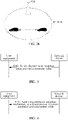
- Three transmission modes are defined in the 3rd Generation Partnership Project (3GPP): mode A and mode B, as shown in FIGs. 2a and 2b , wherein a solid line shows a sidelink and a dashed line shows a Downlink (DL).
- 3GPP 3rd Generation Partnership Project
- a transmission resource of a terminal is allocated by a base station, the base station allocates the resource to the terminal based on a Grant signaling (Grant) through a downlink, and the terminal transmits data on a sidelink according to the resource allocated by the base station; the base station may allocate to the terminal a resource for one-time transmission or a resource for semi-static transmission.
- Grant Grant signaling
- a vehicle-mounted terminal selects a resource in a resource pool for data transmission.
- D2D is studied in different stages.
- ProSe in Release-12/13 (Rel-12/13), Device-to-Device communication has been studied for a ProSe scenario, which mainly aims at public safety services.
- the resource pool is discontinuous in the time domain, so that a UE may transmit/receive data discontinuously on a sidelink, thereby achieving an effect of saving power.
- V2X in Rel-14/15, a V2X system has been studied for a scenario of Vehicle to Vehicle communication, which is mainly for services of relatively high-speed mobile vehicle-vehicle and vehicle-person communication.
- V2X power efficiency is not a main problem since a vehicle-mounted system has continuous power supply, but delay of data transmission is the main problem, so a terminal device is required to perform transmitting and receiving continuously in a system design.
- a conclusion of the 3GPP is that a base station may configure a Discontinuous Reception (DRX) parameter of a remote terminal through a relay terminal in a pre-research stage.
- DRX Discontinuous Reception
- NR V2X is not limited to a broadcast scenario, but is further extended to unicast and multicast scenarios, and an application of V2X is studied in these scenarios.
- mode-A/B Similar to LTE V2X, the above two resource authorization modes of mode-A/B will also be defined for NR V2X. Furthermore, a user may be in a mixed mode, that is, the mode-A may be used for resource acquisition and the mode-B may be used for resource acquisition at the same time.
- NR V2X which is not limited to unicast communication, but also includes multicast communication.
- a main problem of how to design the power saving mechanism of the sidelink is that, for a same UE, the UE also has power saving requirements for different requirements: power saving requirements under different transmission modes, such as broadcast, multicast, and unicast; power saving requirements under different services; power saving requirements under Different Radio Access Technologies (RATs); and power saving requirements under different interfaces, including Uu (User Equipment) and PC5.
- RATs Radio Access Technologies
- an embodiment of the present application provides a method for processing a discontinuous reception parameter.
- FIG. 3 is a schematic flowchart of a first method for processing a discontinuous reception parameter according to an embodiment of the present application. The method may be performed by a network device.
- the method includes an act S302.
- act S302 a discontinuous reception parameter and a parameter value are sent to a user equipment.
- Discontinuous reception parameters corresponding to different communication parameters are different, or values of discontinuous reception parameters corresponding to different communication parameters are different.
- a communication parameter includes at least one of following: a transmission mode, a service type, a Radio Access Technology type, an interface type, and a carrier frequency.
- a device performing the above act S302 may be a network device, which may be the network device as shown in FIG. 1 , and may transmit the DRX parameter and the parameter value to the user equipment. Data may be transmitted between UEs through a sidelink, and the UEs may be terminal devices as shown in FIG. 1 .
- communication parameters used by the UE are different for different requirements. In order to meet power saving requirements under different requirements, different DRX parameters may be set for different communication parameters, or a same DRX parameter may be set for different communication parameters, but values of the DRX parameter are different.
- the UE may perform a configuration based on the received DRX parameter and parameter value, so that the UE discontinuously transmits/receives data on a sidelink, thereby achieving an effect of saving power.
- the UE discontinuously sends/receives a PC5-S signaling, such as a Direct Communication Request (DCR) message, on a sidelink.
- DCR Direct Communication Request
- the UE discontinuously sends/receives a discovery message on a sidelink.
- the user equipment may perform a configuration based on the received discontinuous reception parameter and parameter value, wherein, discontinuous reception parameters corresponding to different communication parameters are different, or values of discontinuous reception parameters corresponding to different communication parameters are different.
- different DRX parameters or parameter values may be set, so that the UE may transmit/receive data discontinuously in a case of coexistence of different scenarios, thereby achieving an effect of power saving, and solving a technical problem that a user equipment transmits data (such as a Direct Communication Request (DCR) message or a discovery message) on a sidelink in the related technologies, which consumes a large amount of power and cannot achieve a purpose of power saving.
- DCR Direct Communication Request
- different DRX parameters for different transmission modes (broadcast, multicast, and unicast), different DRX parameters, or a same DRX parameter but different DRX parameter values, may be used.
- a discontinuous reception parameter includes at least one of following: a discontinuous reception period, a time offset, a length of discontinuous reception on-duration (ondurationtimer), a length of a discontinuous reception activity timer (inactivitytimer), and a time length of a retransmission timer (retransmissiontimer).
- a transmission mode in a case that a transmission mode is a first mode, it is determined to use a first discontinuous reception parameter; in a case that the transmission mode is a second mode, it is determined to use a second discontinuous reception parameter; wherein parameters included in the first discontinuous reception parameters are at least partially different or all different from parameters included in the second discontinuous reception parameters, or values of parameters included in the first discontinuous reception parameters are at least partially different or all different from values of parameters included in the second discontinuous reception parameters.
- a DRX period is used for a broadcast mode, a time offset is used for a multicast mode, and a DRX on-duration length is used for a unicast mode.
- a DRX period is used for both a broadcast mode and a multicast mode, but parameter values of the DRX period are different.
- a DRX on-duration length is used for a unicast mode.
- a DRX period and a time offset are used for a broadcast mode
- a time offset and a DRX activity timer are used for a multicast mode
- a DRX on-duration length and a time length of a retransmission timer are used for a unicast mode.
- a DRX period and a time offset are used for both a broadcast mode and a multicast mode, but parameter values of the DRX period are different, and parameter values of the time offset are also different.
- a DRX on-duration length is used for a unicast mode.
- a discontinuous reception parameter is sent through at least one of following signaling: a Radio Resource Control (RRC) signaling, a System Information Block (SIB) message, and a pre-configuration signaling.
- RRC Radio Resource Control
- SIB System Information Block
- DRX parameters for different services/service types, different DRX parameters, or a same DRX parameter but different DRX parameter values, may be used.
- a discontinuous reception parameter includes at least one of following: a DRX period, a time offset, a length of DRX on-duration (ondurationtimer), a length of a DRX activity timer (inactivitytimer), and a time length of a retransmission timer (retransmissiontimer).
- a service type in a case that a service type is a first type, it is determined to use a first discontinuous reception parameter; in a case that the service type is a second type, it is determined to use a second discontinuous reception parameter; wherein parameters included in the first discontinuous reception parameters are at least partially different or all different from parameters included in the second discontinuous reception parameters, or values of parameters included in the first discontinuous reception parameters are at least partially different or all different from values of parameters included in the second discontinuous reception parameters.
- a DRX period is used for the first type, and a time offset is used for the second type.
- a DRX period is used for both the first type and the second type, but parameter values of the DRX period are different.
- a DRX period and a time offset are used for the first type, and a time offset and a DRX activity timer are used for the second type.
- a DRX period and a time offset are used for both the first type and the second type, but parameter values of the DRX period are different and parameter values of the time offset are also different.
- a discontinuous reception parameter is sent through at least one of following signaling: an RRC signaling, a SIB message, and a pre-configuration signaling.
- a service type is determined based on a source address, a logical channel identifier, a target address, a Provider Service Identifier (PSID), an Intelligent Transportation Systems Application Identifier (ITSAID), a service priority, a PC5 5G Quality of Service (QoS) Identifier (PC5QI, PQI), a PC5 QoS Flow Identifier (PFI), and/or a QoS attribute identifier.
- PSID Provider Service Identifier
- ITSAID Intelligent Transportation Systems Application Identifier
- QoS PC5 5G Quality of Service
- PQI PC5 QoS Flow Identifier
- QoS attribute identifier a service type may be determined according to different target addresses, PSIDs, ITSAIDs, service priorities, PQIs, PFIs, and QoS attribute identifiers, etc.
- a PC5-S message such as a Direct Communication Request (DCR) message
- a PC5 5G Quality of Service Identifier a PC5 Quality of Service Flow Identifier
- a Quality of Service attribute identifier may be determined according to a QoS set corresponding to a set of services carried on a unicast link associated with the PC5-S message.
- the PC5-S message is a sidelink message based on a PC5 interface.
- DRX parameters for different service types, different DRX parameters, or a same DRX parameter but different DRX parameter values, may be used.
- a discontinuous reception parameter includes at least one of following: a DRX period, a time offset, a length of DRX on-duration (ondurationtimer), a length of a DRX activity timer (inactivitytimer), and a time length of a retransmission timer (retransmissiontimer).
- the user equipment performs the configuration based on the discontinuous reception parameter and the parameter value, including: it is determined to use a first discontinuous reception parameter in a case that a service type is a first type; the user equipment determines to use a second discontinuous reception parameter in a case that the service type does not include the first type and includes a second type.
- parameters included in the first discontinuous reception parameters are at least partially different or all different from parameters included in the second discontinuous reception parameters, or values of parameters included in the first discontinuous reception parameters are at least partially different or all different from values of parameters included in the second discontinuous reception parameters.
- a DRX period is used for the first type, and a time offset is used for the second type.
- a DRX period is used for both the first type and the second type, but parameter values of the DRX period are different.
- a DRX period and a time offset are used for the first type, and a time offset and a DRX activity timer are used for the second type.
- a DRX period and a time offset are used for both the first type and the second type, but parameter values of the DRX period are different and parameter values of the time offset are also different.
- a discontinuous reception parameter is received through at least one of following signaling: an RRC signaling, a SIB message, and a pre-configuration signaling.
- a service type is determined based on a source address, a logical channel identifier, a target address, a Provider Service Identifier (PSID), an Intelligent Transportation Systems Application Identifier (ITSAID), a service priority, a PC5 5G Quality of Service (QoS) Identifier (PC5QI, PQI), a PC5 QoS Flow Identifier (PFI), and/or a QoS attribute identifier.
- PSID Provider Service Identifier
- ITSAID Intelligent Transportation Systems Application Identifier
- QoS PC5 5G Quality of Service
- PQI PC5 QoS Flow Identifier
- QoS attribute identifier a service type may be determined according to different target addresses, PSIDs, ITSAIDs, service priorities, PQIs, PFIs, and QoS attribute identifiers, etc.
- a PC5-S message such as a Direct Communication Request (DCR) message
- a PC5 5G Quality of Service Identifier a PC5 Quality of Service Flow Identifier
- a Quality of Service attribute identifier may be determined according to a QoS set corresponding to a set of services carried on a unicast link associated with the PC5-S message.
- the PC5-S message is a sidelink message based on a PC5 interface.
- the service type refers to a service type associated with a service carried on a unicast communication link.
- DRX parameters for different RAT types, different DRX parameters, or a same DRX parameter but different DRX parameter values, may be used.
- a discontinuous reception parameter includes at least one of following: a DRX period, a time offset, a length of DRX on-duration (ondurationtimer), a length of a DRX activity timer (inactivitytimer), and a time length of a retransmission timer (retransmissiontimer).
- a RAT type in a case that a RAT type is a first type, it is determined to use a first discontinuous reception parameter; in a case that the RAT type is a second type, it is determined to use a second discontinuous reception parameter; wherein parameters included in the first discontinuous reception parameters are at least partially different or all different from parameters included in the second discontinuous reception parameters, or values of parameters included in the first discontinuous reception parameters are at least partially different or all different from values of parameters included in the second discontinuous reception parameters.
- a DRX period is used for LTE and a time offset is used for NR.
- a DRX period is used for both LTE and NR, but parameter values of the DRX period are different.
- a DRX period and a time offset are used for LTE, and a time offset and a DRX activity timer are used for NR.
- a DRX period and a time offset are used for both LTE and NR, but parameter values of the DRX period are different and parameter values of the time offset are also different.
- a discontinuous reception parameter is sent through at least one of following signaling: an RRC signaling, a SIB message, and a pre-configuration signaling.
- a RAT type includes: LTE and NR, or different releases of LTE/NR.
- DRX parameters for different interface types, different DRX parameters, or a same DRX parameter but different DRX parameter values, may be used.
- a discontinuous reception parameter includes at least one of following: a DRX period, a time offset, a length of DRX on-duration (ondurationtimer), a length of a DRX activity timer (inactivitytimer), and a time length of a retransmission timer (retransmissiontimer).
- an interface type in a case that an interface type is a first type, it is determined to use a first discontinuous reception parameter; in a case that the interface type is a second type, it is determined to use a second discontinuous reception parameter; wherein parameters included in the first discontinuous reception parameters are at least partially different or all different from parameters included in the second discontinuous reception parameters, or values of parameters included in the first discontinuous reception parameters are at least partially different or all different from values of parameters included in the second discontinuous reception parameters.
- a DRX period is used for a Uu interface and a time offset is used for a PC5 interface.
- a DRX period is used for both a Uu interface and a PC5 interface, but parameter values for the DRX period are different.
- a DRX period and a time offset are used for a Uu interface, and a time offset and a DRX activity timer are used for a PC5 interface.
- a DRX period and a time offset are used for both a Uu interface and a PC5 interface, but parameter values of the DRX period are different and parameter values of the time offset are also different.
- a discontinuous reception parameter is sent through at least one of following signaling: an RRC signaling, a SIB message, and a pre-configuration signaling.
- An interface type includes: a Uu interface and a PC5 interface.
- different DRX parameters For different interface types, different DRX parameters, or a same DRX parameter but different DRX parameter values, are used, including: a first parameter reported by a user equipment is received, wherein, the first parameter is used for determining a value of a discontinuous reception parameter corresponding to a PC5 interface. That is, a UE reports a first parameter to a network, the first parameter is input information for calculating a PC5 DRX parameter value, and the calculated PC5 DRX parameter value is returned to the UE.
- the first parameter includes at least one piece of following information of the UE: identity information of the UE, transmission mode information, source address information, PQI, PFI, and QoS attribute information, etc.
- a value of a discontinuous reception parameter corresponding to a user equipment interface is sent to the user equipment, wherein the user equipment is used for determining a value of a discontinuous reception parameter corresponding to a PC5 interface based on the value of the discontinuous reception parameter corresponding to the user equipment interface. That is, a network delivers only a first DRX parameter value used by a Uu, and a UE deduces a second DRX parameter value used by a PC5 according to the first DRX parameter value used by the Uu.
- DRX parameters for different carrier frequencies/bands/frequency ranges, different DRX parameters, or a same DRX parameter but different DRX parameter values, may be used.
- a discontinuous reception parameter includes at least one of following: a DRX period, a time offset, a length of DRX on-duration (ondurationtimer), a length of a DRX activity timer (inactivitytimer), and a time length of a retransmission timer (retransmissiontimer).
- a carrier frequency in a case that a carrier frequency is a first frequency, it is determined to use a first discontinuous reception parameter; in a case that the carrier frequency is a second frequency, it is determined to use a second discontinuous reception parameter; wherein parameters included in the first discontinuous reception parameters are at least partially different or all different from parameters included in the second discontinuous reception parameters, or values of parameters included in the first discontinuous reception parameters are at least partially different or all different from values of parameters included in the second discontinuous reception parameters.
- a DRX period is used for the first frequency, and a time offset is used for the second frequency.
- a DRX period is used for both the first frequency and the second frequency, but parameter values of the DRX period are different.
- a DRX period and a time offset are used for the first frequency, and a time offset and a DRX activity timer are used for the second frequency.
- a DRX period and a time offset are used for both the first frequency and the second frequency, but parameter values of the DRX period are different and parameter values of the time offset are also different.
- a discontinuous reception parameter is sent through at least one of following signaling: an RRC signaling, a SIB message, and a pre-configuration signaling.
- FIG. 4 is a schematic flowchart of a second method for processing a discontinuous reception parameter according to an embodiment of the present application. The method may also be performed by a network device.
- the method includes an act S402.
- a discontinuous reception mechanism or a discontinuous reception parameter and a parameter value, are sent to a user equipment.
- a specific message may be a PC5-S signaling or a discovery message, for example, the PC5-S signaling may be a Direct Communication Request (DCR) message.
- DCR Direct Communication Request
- a device performing the above act S402 may be a network device, which may be the network device as shown in FIG. 1 , and may transmit the DRX mechanism, or the DRX parameter and the parameter value, to the user equipment.
- Data may be transmitted between UEs through a sidelink, and the UEs may be terminal devices as shown in FIG. 1 .
- different DRX mechanisms or DRX parameters may be set for transmission/reception of specific messages, or a same DRX parameter may be set for different specific messages but values of the DRX parameter are different.
- the UE may perform a configuration based on the received DRX mechanism, or DRX parameter and parameter value, so that the UE discontinuously transmits/receives data on a sidelink, thereby achieving an effect of saving power.
- the user equipment may perform a configuration based on the received discontinuous reception mechanism, or discontinuous reception parameter and parameter value, wherein discontinuous reception mechanisms or discontinuous reception parameters corresponding to different specific messages are different, or values of discontinuous reception parameters corresponding to different specific messages are different.
- DRX mechanisms for transmission/reception of specific messages, different DRX mechanisms, or DRX parameters, or parameter values may be set, so that a UE may transmit/receive data discontinuously in this scenario, thus achieving an effect of saving power, thereby solving a technical problem that a user equipment transmits data (such as a Direct Communication Request (DCR) message or a discovery message) on a sidelink in the related technologies, which consumes a large amount of power and cannot achieve a purpose of power saving.
- DCR Direct Communication Request
- the transmission/reception of specific messages triggers different DRX mechanisms, or different DRX parameters, or different values of DRX parameters.
- a discontinuous reception parameter includes at least one of following: a DRX period, a time offset, a length of DRX on-duration (ondurationtimer), a length of a DRX activity timer (inactivitytimer), and a time length of a retransmission timer (retransmissiontimer).
- a specific message in a case that a specific message is a first message, it is determined to use a first discontinuous reception parameter; in a case that the specific message is a second message, it is determined to use a second discontinuous reception parameter; wherein parameters included in the first discontinuous reception parameters are at least partially different or all different from parameters included in the second discontinuous reception parameters, or values of parameters included in the first discontinuous reception parameters are at least partially different or all different from values of parameters included in the second discontinuous reception parameters.
- a DRX period is used for a first message, a time offset is used for a second message, and a DRX on-duration length is used for a third message.
- a DRX period is used for both the first message and the second message, but parameter values of the DRX period are different.
- a DRX on-duration length is used for the third message.
- a DRX period and a time offset are used for the first message
- a time offset and a DRX activity timer are used for the second message
- a DRX on-duration length and a time length of a retransmission timer are used for the third message.
- a DRX period and a time offset are used for both the first message and the second message, but parameter values of the DRX period are different and parameter values of the time offset are also different.
- a DRX on-duration length is used for the third message.
- a discontinuous reception parameter is sent through at least one of following signaling: an RRC signaling, a SIB message, and a pre-configuration signaling.
- a first discontinuous reception timer in a case that a specific message is a first message. And/or, in a case that the specific message is a second message, it is determined to enter a discontinuous reception state. And/or, in a case that the specific message is a third message, it is determined to enter an active state.
- DRX parameters/parameter values are used for different messages/directions, including:
- FIG. 5 is a schematic flowchart of a third method for processing a discontinuous reception parameter according to an embodiment of the present application. The method may be performed by a user equipment.
- the method includes acts S502 and S504.
- a user equipment receives a discontinuous reception parameter and a parameter value.
- act S504 the user equipment performs a configuration based on the discontinuous reception parameter and the parameter value.
- Discontinuous reception parameters corresponding to different communication parameters are different, or values of discontinuous reception parameters corresponding to different communication parameters are different.
- a communication parameter includes at least one of following: a transmission mode, a service type, a Radio Access Technology type, an interface type, and a carrier frequency.
- a device sending the discontinuous reception parameter and the parameter value may be a network device, which may be the network device as shown in FIG. 1 , and may transmit the DRX parameter and the parameter value to the user equipment.
- Data may be transmitted between UEs through a sidelink, the UEs may be terminal devices as shown in FIG. 1 .
- communication parameters used by the UE are different for different requirements.
- different DRX parameters may be set for different communication parameters, or a same DRX parameter may be set for different communication parameters, but values of the DRX parameter are different.
- the UE may perform a configuration based on the received DRX parameter and parameter value, so that the UE discontinuously transmits/receives data on a sidelink, thereby achieving an effect of saving power.
- different DRX parameters for different transmission modes (broadcast, multicast, and unicast), different DRX parameters, or a same DRX parameter but different DRX parameter values, may be used.
- a discontinuous reception parameter includes at least one of following: a DRX period, a time offset, a length of DRX on-duration (ondurationtimer), a length of a DRX activity timer (inactivitytimer), and a time length of a retransmission timer (retransmissiontimer).
- the user equipment performs the configuration based on the discontinuous reception parameter and the parameter value, including: in a case that a transmission mode is a first mode, it is determined to use a first discontinuous reception parameter; in a case that the transmission mode is a second mode, it is determined to use a second discontinuous reception parameter; wherein parameters included in the first discontinuous reception parameters are at least partially different or all different from parameters included in the second discontinuous reception parameters, or values of parameters included in the first discontinuous reception parameters are at least partially different or all different from values of parameters included in the second discontinuous reception parameters.
- a DRX period is used for a broadcast mode, a time offset is used for a multicast mode, and a DRX on-duration length is used for a unicast mode.
- a DRX period is used for both a broadcast mode and a multicast mode, but parameter values of the DRX period are different.
- a DRX on-duration length is used for a unicast mode.
- a DRX period and a time offset are used for a broadcast mode
- a time offset and a DRX activity timer are used for a multicast mode
- a DRX on-durationlength and a time length of a retransmission timer are used for a unicast mode.
- a DRX period and a time offset are used for both a broadcast mode and a multicast mode, but parameter values of the DRX period are different, and parameter values of the time offset are also different.
- a DRX on-duration length is used for a unicast mode.
- a discontinuous reception parameter is received through at least one of following signaling: an RRC signaling, a SIB message, and a pre-configuration signaling.
- DRX parameters for different service types, different DRX parameters, or a same DRX parameter but different DRX parameter values, may be used.
- a discontinuous reception parameter includes at least one of following: a DRX period, a time offset, a length of DRX on-duration (ondurationtimer), a length of a DRX activity timer (inactivitytimer), and a time length of a retransmission timer (retransmissiontimer).
- the user equipment performs the configuration based on the discontinuous reception parameter and the parameter value, including: in a case that a service type is a first type, it is determined to use a first discontinuous reception parameter; in a case that the service type is a second type, it is determined to use a second discontinuous reception parameter; wherein parameters included in the first discontinuous reception parameters are at least partially different or all different from parameters included in the second discontinuous reception parameters, or values of parameters included in the first discontinuous reception parameters are at least partially different or all different from values of parameters included in the second discontinuous reception parameters.
- a DRX period is used for the first type, and a time offset is used for the second type.
- a DRX period is used for both the first type and the second type, but parameter values of the DRX period are different.
- a DRX period and a time offset are used for the first type, and a time offset and a DRX activity timer are used for the second type.
- a DRX period and a time offset are used for both the first type and the second type, but parameter values of the DRX period are different and parameter values of the time offset are also different.
- a discontinuous reception parameter is received through at least one of following signaling: an RRC signaling, a SIB message, and a pre-configuration signaling.
- a service type is determined based on a source address, a logical channel identifier, a target address, a Provider Service Identifier (PSID), an Intelligent Transportation Systems Application Identifier (ITSAID), a service priority, a PC5 5G Quality of Service (QoS) Identifier (PC5QI, PQI), a PC5 QoS Flow Identifier (PFI), and/or a QoS attribute identifier.
- PSID Provider Service Identifier
- ITSAID Intelligent Transportation Systems Application Identifier
- QoS PC5 5G Quality of Service
- PQI PC5 QoS Flow Identifier
- QoS attribute identifier a service type may be determined according to different target addresses, PSIDs, ITSAIDs, service priorities, PQIs, PFIs, and QoS attribute identifiers, etc.
- a PC5-S message such as a Direct Communication Request (DCR) message
- a PC5 5G Quality of Service Identifier a PC5 Quality of Service Flow Identifier
- a Quality of Service attribute identifier may be determined according to a QoS set corresponding to a set of services carried on a unicast link associated with the PC5-S message.
- the PC5-S message is a sidelink message based on a PC5 interface.
- DRX parameters for different service types, different DRX parameters, or a same DRX parameter but different DRX parameter values, may be used.
- a discontinuous reception parameter includes at least one of following: a DRX period, a time offset, a length of DRX on-duration (ondurationtimer), a length of a DRX activity timer (inactivitytimer), and a time length of a retransmission timer (retransmissiontimer).
- the user equipment performs the configuration based on the discontinuous reception parameter and the parameter value, including: the user equipment determines to use a first discontinuous reception parameter in a case that a service type is a first type; the user equipment determines to use a second discontinuous reception parameter in a case that the service type does not include the first type and includes a second type; wherein parameters included in the first discontinuous reception parameters are at least partially different or all different from parameters included in the second discontinuous reception parameters, or values of parameters included in the first discontinuous reception parameters are at least partially different or all different from values of parameters included in the second discontinuous reception parameters.
- a DRX period is used for the first type, and a time offset is used for the second type.
- a DRX period is used for both the first type and the second type, but parameter values of the DRX period are different.
- a DRX period and a time offset are used for the first type, and a time offset and a DRX activity timer are used for the second type.
- a DRX period and a time offset are used for both the first type and the second type, but parameter values of the DRX period are different and parameter values of the time offset are also different.
- a discontinuous reception parameter is received through at least one of following signaling: an RRC signaling, a SIB message, and a pre-configuration signaling.
- a service type is determined based on a source address, a logical channel identifier, a target address, a Provider Service Identifier (PSID), an Intelligent Transportation Systems Application Identifier (ITSAID), a service priority, a PC5 5G Quality of Service (QoS) Identifier (PC5QI, PQI), a PC5 QoS Flow Identifier (PFI), and/or a QoS attribute identifier.
- PSID Provider Service Identifier
- ITSAID Intelligent Transportation Systems Application Identifier
- QoS PC5 5G Quality of Service
- PQI PC5 QoS Flow Identifier
- QoS attribute identifier a service type may be determined according to different target addresses, PSIDs, ITSAIDs, service priorities, PQIs, PFIs, and QoS attribute identifiers, etc.
- a PC5-S message such as a Direct Communication Request (DCR) message
- a PC5 5G Quality of Service Identifier a PC5 Quality of Service Flow Identifier
- a Quality of Service attribute identifier may be determined according to a QoS set corresponding to a set of services carried on a unicast link associated with the PC5-S message.
- the PC5-S message is a sidelink message based on a PC5 interface.
- the service type refers to a service type associated with a service carried on a unicast communication link.
- DRX parameters for different RAT types, different DRX parameters, or a same DRX parameter but different DRX parameter values, may be used.
- a discontinuous reception parameter includes at least one of following: a DRX period, a time offset, a length of DRX on-duration (ondurationtimer), a length of a DRX activity timer (inactivitytimer), and a time length of a retransmission timer (retransmissiontimer).
- the user equipment performs the configuration based on the discontinuous reception parameter and the parameter value, including: in a case that a RAT type is a first type, it is determined to use a first discontinuous reception parameter; in a case that the RAT type is a second type, it is determined to use a second discontinuous reception parameter; wherein parameters included in the first discontinuous reception parameters are at least partially different or all different from parameters included in the second discontinuous reception parameters, or values of parameters included in the first discontinuous reception parameters are at least partially different or all different from values of parameters included in the second discontinuous reception parameters.
- a DRX period is used for LTE and a time offset is used for NR.
- a DRX period is used for both LTE and NR, but parameter values of the DRX period are different.
- a DRX period and a time offset are used for LTE, and a time offset and a DRX activity timer are used for NR.
- a DRX period and a time offset are used for both LTE and NR, but parameter values of the DRX period are different and parameter values of the time offset are also different.
- a discontinuous reception parameter is received through at least one of following signaling: an RRC signaling, a SIB message, and a pre-configuration signaling.
- a RAT type includes: LTE and NR, or different releases of LTE/NR.
- DRX parameters for different interface types, different DRX parameters, or a same DRX parameter but different DRX parameter values, may be used.
- a discontinuous reception parameter includes at least one of following: a DRX period, a time offset, a length of DRX on-duration (ondurationtimer), a length of a DRX activity timer (inactivitytimer), and a time length of a retransmission timer (retransmissiontimer).
- the user equipment performs the configuration based on the discontinuous reception parameter and the parameter value, including: in a case that an interface type is a first type, it is determined to use a first discontinuous reception parameter; in a case that the interface type is a second type, it is determined to use a second discontinuous reception parameter; wherein parameters included in the first discontinuous reception parameters are at least partially different or all different from parameters included in the second discontinuous reception parameters, or values of parameters included in the first discontinuous reception parameters are at least partially different or all different from values of parameters included in the second discontinuous reception parameters.
- a DRX period is used for a Uu interface and a time offset is used for a PC5 interface.
- a DRX period is used for both a Uu interface and a PC5 interface, but parameter values for the DRX period are different.
- a DRX period and a time offset are used for a Uu interface, and a time offset and a DRX activity timer are used for a PC5 interface.
- a DRX period and a time offset are used for both a Uu interface and a PC5 interface, but parameter values of the DRX period are different and parameter values of the time offset are also different.
- a discontinuous reception parameter is received through at least one of following signaling: an RRC signaling, a SIB message, and a pre-configuration signaling.
- An interface type includes: a Uu interface and a PC5 interface.
- DRX parameters For different interface types, different DRX parameters, or a same DRX parameter but different DRX parameter values, are used, including: a user equipment reports a first parameter, wherein, the first parameter is used for determining a value of a discontinuous reception parameter corresponding to a PC5 interface. That is, a network device receives a first parameter reported by a UE, calculates a PC5 DRX parameter value based on the first parameter, and returns the calculated PC5 DRX parameter value to the UE.
- the first parameter includes at least one piece of following information of the UE: identity information of the UE, transmission mode information, source address information, PQI, PFI, and QoS attribute information, etc.
- the user equipment After receiving a value of a discontinuous reception parameter corresponding to a user equipment interface, the user equipment determines a value of a discontinuous reception parameter corresponding to a PC5 interface based on the value of the discontinuous reception parameter corresponding to the user equipment interface. That is, a network delivers only a first DRX parameter value used by a Uu, and a UE deduces a second DRX parameter value used by a PC5 according to the first DRX parameter value used by the Uu.
- DRX parameters for different carrier frequencies/bands/frequency ranges, different DRX parameters, or a same DRX parameter but different DRX parameter values, may be used.
- a discontinuous reception parameter includes at least one of following: a DRX period, a time offset, a length of DRX on-duration (ondurationtimer), a length of a DRX activity timer (inactivitytimer), and a time length of a retransmission timer (retransmissiontimer).
- the user equipment performs the configuration based on the discontinuous reception parameter and the parameter value, including: in a case that a carrier frequency is a first frequency, the user equipment determines to use a first discontinuous reception parameter; in a case that the carrier frequency is a second frequency, the user equipment determines to use a second discontinuous reception parameter; wherein parameters included in the first discontinuous reception parameters are at least partially different or all different from parameters included in the second discontinuous reception parameters, or values of parameters included in the first discontinuous reception parameters are at least partially different or all different from values of parameters included in the second discontinuous reception parameters.
- a DRX period is used for the first frequency, and a time offset is used for the second frequency.
- a DRX period is used for both the first frequency and the second frequency, but parameter values of the DRX period are different.
- a DRX period and a time offset are used for the first frequency, and a time offset and a DRX activity timer are used for the second frequency.
- a DRX period and a time offset are used for both the first frequency and the second frequency, but parameter values of the DRX period are different and parameter values of the time offset are also different.
- a discontinuous reception parameter is received through at least one of following signaling: an RRC signaling, a SIB message, and a pre-configuration signaling.
- FIG. 6 is a schematic flowchart of a fourth method for processing a discontinuous reception parameter according to an embodiment of the present application. The method may be performed by a user equipment.
- the method includes acts S602 and S604.
- a user equipment receives a discontinuous reception mechanism, or a discontinuous reception parameter and a parameter value.
- act S604 the user equipment performs a configuration based on the discontinuous reception mechanism, or the discontinuous reception parameter and the parameter value.
- Discontinuous reception mechanisms or discontinuous reception parameters corresponding to different specific messages are different, or values of discontinuous reception parameters corresponding to different specific messages are different.
- a device sending the discontinuous reception mechanism, or the discontinuous reception parameter and the parameter value may be a network device, which may be the network device as shown in FIG. 1 , and may transmit the DRX mechanism, or the DRX parameter and the parameter value to the user equipment.
- Data may be transmitted between UEs through a sidelink, and the UEs may be terminal devices as shown in FIG. 1 .
- different DRX mechanisms or DRX parameters may be set for transmission/reception of specific messages, or a same DRX parameter may be set for different specific messages but values of the DRX parameter are different.
- the UE may perform a configuration based on the received DRX mechanism, or DRX parameter and parameter value, so that the UE discontinuously transmits/receives data on a sidelink, thereby achieving an effect of saving power.
- the transmission/reception of specific messages triggers different DRX mechanisms, or different DRX parameters, or different values of DRX parameters.
- a discontinuous reception parameter includes at least one of following: a DRX period, a time offset, a length of DRX on-duration (ondurationtimer), a length of a DRX activity timer (inactivitytimer), and a time length of a retransmission timer (retransmissiontimer).
- the user equipment performs the configuration based on the discontinuous reception mechanism, or the discontinuous reception parameter and the parameter value, including: in a case that a specific message is a first message, it is determined to use a first discontinuous reception parameter; in a case that the specific message is a second message, it is determined to use a second discontinuous reception parameter; wherein parameters included in the first discontinuous reception parameters are at least partially different or all different from parameters included in the second discontinuous reception parameters, or values of parameters included in the first discontinuous reception parameters are at least partially different or all different from values of parameters included in the second discontinuous reception parameters.
- a DRX period is used for a first message, a time offset is used for a second message, and a DRX on-duration length is used for a third message.
- a DRX period is used for both the first message and the second message, but parameter values of the DRX period are different.
- a DRX on-duration length is used for the third message.
- a DRX period and a time offset are used for the first message
- a time offset and a DRX activity timer are used for the second message
- a DRX on-duration length and a time length of a retransmission timer are used for the third message.
- a DRX period and a time offset are used for both the first message and the second message, but parameter values of the DRX period are different and parameter values of the time offset are also different.
- a DRX on-duration length is used for the third message.
- a discontinuous reception parameter is received through at least one of following signaling: an RRC signaling, a SIB message, and a pre-configuration signaling.
- the user equipment performs the configuration based on the discontinuous reception mechanism, or the discontinuous reception parameter and the parameter value, including: the user equipment determines to start a first discontinuous reception timer in a case that a specific message is a first message. And/or, the user equipment performs the configuration based on the discontinuous reception mechanism, or the discontinuous reception parameter and the parameter value, including: the user equipment determines to enter a discontinuous reception state in a case that a specific message is a second message. And/or, the user equipment performs the configuration based on the discontinuous reception mechanism, or the discontinuous reception parameter and the parameter value, including: the user equipment determines to enter an active state in a case that a specific message is a first message.
- different DRX parameters/parameter values are used for different messages/directions, including: reception or transmission of a first message starts a first DRX timer; reception or transmission of a second message enables a UE to enter a DRX state; and reception or transmission of a third message enables the UE to enter an active state.
- sequence numbers of various processes do not imply an order of execution of the various processes, which should be determined by their functions and internal logics, but should not constitute any limitation on implementation processes of the embodiments of the present application.
- the method for processing a discontinuous reception parameter according to the embodiments of the present application is described in detail above with reference to FIG. 1 to FIG.6 .
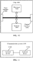
- a terminal device and a network device according to the embodiments of the present application will be described below with reference to FIG. 7 to FIG. 9 .
- a network device 700 includes a communication module 702.
- the communication module 702 is configured to send a discontinuous reception parameter and a parameter value to a user equipment; wherein discontinuous reception parameters corresponding to different communication parameters are different, or values of discontinuous reception parameters corresponding to different communication parameters are different.
- the communication module 702 is further configured to receive a first parameter reported by the user equipment, wherein the first parameter is used for determining a value of a discontinuous reception parameter corresponding to a PC5 interface.
- the communication module 702 is further configured to send a value of a discontinuous reception parameter corresponding to a user equipment interface to the user equipment, wherein the user equipment is configured to determine a value of a discontinuous reception parameter corresponding to a PC5 interface based on the value of the discontinuous reception parameter corresponding to the user equipment interface.
- the communication module 702 is configured to send a discontinuous reception mechanism, or a discontinuous reception parameter and a parameter value, to the user equipment; wherein discontinuous reception mechanisms or discontinuous reception parameters corresponding to different specific messages are different, or values of discontinuous reception parameters corresponding to different specific messages are different.
- a user equipment 800 includes a communication module 802 and a processing module 804.
- the communication module 802 is configured to receive a discontinuous reception parameter and a parameter value, wherein discontinuous reception parameters corresponding to different communication parameters are different, or values of discontinuous reception parameters corresponding to different communication parameters are different; and the processing module 804 is configured to perform a configuration based on the discontinuous reception parameter and the parameter value.
- a communication parameter includes: a transmission mode.
- the processing module 804 is further configured to determine to use a first discontinuous reception parameter in a case that the transmission mode is a first mode; and determine to use a second discontinuous reception parameter in a case that the transmission mode is a second mode.
- parameters included in the first discontinuous reception parameters are at least partially different or all different from parameters included in the second discontinuous reception parameters, or values of parameters included in the first discontinuous reception parameters are at least partially different or all different from values of parameters included in the second discontinuous reception parameters.
- the communication parameter includes: a service type.
- the processing module 804 is further configured to determine to use a first discontinuous reception parameter in a case that the service type is a first type; and determine to use a second discontinuous reception parameter in a case that the service type is a second type.
- parameters included in the first discontinuous reception parameters are at least partially different or all different from parameters included in the second discontinuous reception parameters, or values of parameters included in the first discontinuous reception parameters are at least partially different or all different from values of parameters included in the second discontinuous reception parameters.
- the communication parameter includes: a RAT type.
- the processing module 804 is further configured to determine to use a first discontinuous reception parameter in a case that the RAT type is a first type; and determine to use a second discontinuous reception parameter in a case that the RAT type is a second type.
- parameters included in the first discontinuous reception parameters are at least partially different or all different from parameters included in the second discontinuous reception parameters, or values of parameters included in the first discontinuous reception parameters are at least partially different or all different from values of parameters included in the second discontinuous reception parameters.
- the communication parameter includes: an interface type.
- the processing module 804 is further configured to determine to use a first discontinuous reception parameter in a case that the interface type is a first type; and determine to use a second discontinuous reception parameter in a case that the interface type is a second type. Wherein parameters included in the first discontinuous reception parameters are at least partially different or all different from parameters included in the second discontinuous reception parameters, or values of parameters included in the first discontinuous reception parameters are at least partially different or all different from values of parameters included in the second discontinuous reception parameters.
- the communication module 802 is further configured to report a first parameter, wherein the first parameter is used for determining a value of a discontinuous reception parameter corresponding to a PC5 interface.
- the processing module 804 is further configured to determine a value of a discontinuous reception parameter corresponding to a PC5 interface based on a value of a discontinuous reception parameter corresponding to a user equipment interface after receiving the value of the discontinuous reception parameter corresponding to the user equipment interface.
- the communication parameter includes: a carrier frequency.
- the processing module 804 is further configured to determine to use a first discontinuous reception parameter in a case that the carrier frequency is a first frequency; and determine to use a second discontinuous reception parameter in a case that the carrier frequency is a second frequency.
- parameters included in the first discontinuous reception parameters are at least partially different or all different from parameters included in the second discontinuous reception parameters, or values of parameters included in the first discontinuous reception parameters are at least partially different or all different from values of parameters included in the second discontinuous reception parameters.
- the communication module 802 is further configured to receive a discontinuous reception mechanism, or a discontinuous reception parameter and a parameter value, wherein discontinuous reception mechanisms or discontinuous reception parameters corresponding to different specific messages are different, or values of discontinuous reception parameters corresponding to different specific messages are different; and the processing module 804 is configured to perform a configuration based on the discontinuous reception mechanism, or the discontinuous reception parameter and the parameter value.
- the processing module 804 is further configured to determine to start a first discontinuous reception timer in a case that a specific message is a first message.
- the first message may be a PC5-S signaling or a discovery message, for example, the PC5-S signaling may be a Direct Communication Request (DCR) message.
- DCR Direct Communication Request
- the processing module 804 is further configured to determine to enter a discontinuous reception state in a case that a specific message is a second message.
- the processing module 804 is further configured to determine to enter an active state in a case that a specific message is a first message.
- the processing module 804 is further configured to determine to use a first discontinuous reception parameter in a case that a specific message is a first message; and determine to use a second discontinuous reception parameter in a case that the specific message is a second message.
- parameters included in the first discontinuous reception parameters are at least partially different or all different from parameters included in the second discontinuous reception parameters, or values of parameters included in the first discontinuous reception parameters are at least partially different or all different from values of parameters included in the second discontinuous reception parameters.
- An embodiment of the present application also provides a storage medium, which includes a stored program, wherein, when the program is running, a device where the storage medium is located is controlled to perform each method of processing a discontinuous reception parameter in the embodiments of the present application.
- An embodiment of the present application also provides a processor, which is configured to run a program, wherein, when the program is running, each method of processing a discontinuous reception parameter in the embodiments of the present application is performed.
- FIG. 9 is a schematic diagram of a structure of a communication device 900 according to an embodiment of the present application.
- the communication device 900 shown in FIG. 9 includes a processor 902 which may call and run a computer program from a memory to implement the methods in the embodiments of the present application.
- the communication device 900 may further include a memory 904.
- the processor 902 may call and run a computer program from the memory 904 to implement the methods in the embodiments of the present application.
- the memory 904 may be a separate device independent of the processor 902, or may be integrated in the processor 904.
- the communication device 900 may further include a transceiver 906, and the processor 902 may control the transceiver 906 to communicate with another device.
- the transceiver 1330 may send information or data to another device or receive information or data sent by another device.
- the transceiver 906 may include a transmitter and a receiver.
- the transceiver 906 may further include antennas, a quantity of which may be one or more.
- the communication device 900 may specifically be the network device according to the embodiments of the present application, and the communication device 900 may implement corresponding processes implemented by the network device in various methods in the embodiments of the present application, which will not be repeated here for brevity.
- the communication device 900 may specifically be the user equipment according to the embodiments of the present application, and the communication device 900 may implement corresponding processes implemented by the user equipment in various methods in the embodiments of the present application, which will not be repeated here for brevity.
- FIG. 10 is a schematic diagram of a structure of a chip according to an embodiment of the present application.
- the chip 1000 shown in FIG. 10 includes a processor 1002, wherein the processor 1002 may call and run a computer program from a memory to implement the methods in the embodiments of the present application.
- the chip 1000 may further include a memory 1004.
- the processor 1002 may call and run a computer program from the memory 1004 to implement the methods in the embodiments of the present application.
- the memory 1004 may be a separate device independent of the processor 1002, or may be integrated in the processor 1002.
- the chip 1000 may further include an input interface 1006.
- the processor 1002 may control the input interface 1006 to communicate with another device or chip.
- the processor 1410 may acquire information or data sent by another device or chip.
- the chip 1000 may further include an output interface 1008.
- the processor 1002 may control the output interface 1008 to communicate with another device or chip.
- the processor 1410 may output information or data to another device or chip.
- the chip may be applied to the network device in the embodiments of the present application, and the chip may implement the corresponding processes implemented by the network device in the various methods of the embodiments of the present application, which will not be repeated here for brevity.
- the chip may be applied to the user equipment in the embodiments of the present application, and the chip may implement the corresponding processes implemented by the user equipment in various methods of the embodiments of the present application, which will not be repeated here for brevity.
- chip mentioned in the embodiments of the present application may also be referred to as a system-level chip, a system chip, a chip system, or a system on chip, etc.
- FIG. 11 is a schematic block diagram of a communication system 1100 according to an embodiment of the present application. As shown in FIG. 11 , the communication system 1100 includes a terminal device 1102 and a network device 1104.
- the terminal device 1102 may be configured to implement corresponding functions implemented by the user equipment in the above-mentioned methods
- the network device 1104 may be configured to implement corresponding functions implemented by the network device in the above-mentioned methods, which will not be repeated here for brevity.
- the processor in the embodiments of the present application may be an integrated circuit chip with a capability for processing signals.
- various acts of the method embodiments described above may be completed through an integrated logic circuit of hardware in a processor or instructions in a form of software.
- the above processor may be a general purpose processor, a Digital Signal Processor (DSP), an Application Specific Integrated Circuit (ASIC), a Field Programmable Gate Array (FPGA), or another programmable logic device, a discrete gate or transistor logic device, or a discrete hardware component.
- DSP Digital Signal Processor
- ASIC Application Specific Integrated Circuit
- FPGA Field Programmable Gate Array
- the processor may implement various methods, acts, and logic block diagrams disclosed in the embodiments of the present application.
- the general purpose processor may be a microprocessor or the processor may be any conventional processor or the like.
- the acts of the methods disclosed in connection with the embodiments of the present application may be directly embodied by execution of a hardware decoding processor, or by execution of a combination of hardware and software modules in a decoding processor.
- the software modules may be located in a storage medium commonly used in the art, such as a random access memory, a flash memory, a read-only memory, a programmable read-only memory or an electrically erasable programmable memory, or a register.
- the storage medium is located in a memory, and a processor reads information in the memory and completes the acts of the above methods in combination with its hardware.
- the memory in the embodiments of the present application may be a transitory memory or a non-transitory memory, or may include both transitory and non-transitory memory.
- the non-transitory memory may be a Read-Only Memory (ROM), a Programmable ROM (PROM), an Erasable PROM (EPROM), an Electrically EPROM (EEPROM), or a flash memory.
- the transitory memory may be a Random Access Memory (RAM) which serves as an external cache.
- RAMs such as a Static RAM (SRAM), a Dynamic RAM (DRAM), a Synchronous DRAM (SDRAM), a Double Data Rate SDRAM (DDR SDRAM), an Enhanced SDRAM (ESDRAM), a Synchlink DRAM (SLDRAM), and a Direct Rambus RAM (DR RAM).
- SRAM Static RAM
- DRAM Dynamic RAM
- SDRAM Synchronous DRAM
- DDR SDRAM Double Data Rate SDRAM
- ESDRAM Enhanced SDRAM
- SLDRAM Synchlink DRAM
- DR RAM Direct Rambus RAM
- the memory in the embodiments of the present application may be a Static RAM (SRAM), a Dynamic RAM (DRAM), a Synchronous DRAM (SDRAM), a Double Data Rate SDRAM (DDR SDRAM), an Enhanced SDRAM (ESDRAM), a Synch Link DRAM (SLDRAM), a Direct Rambus RAM (DR RAM), etc. That is to say, the memories in the embodiments of the present application are intended to include, but are not limited to, these and any other suitable types of memories.
- SRAM Static RAM
- DRAM Dynamic RAM
- SDRAM Synchronous DRAM
- DDR SDRAM Double Data Rate SDRAM
- ESDRAM Enhanced SDRAM
- SLDRAM Synch Link DRAM
- DR RAM Direct Rambus RAM
- An embodiment of the present application further provides a computer readable storage medium, configured to store a computer program.
- the computer readable storage medium may be applied to a network device in an embodiment of the present application, and the computer program enables a computer to perform corresponding processes implemented by the network device in various methods according to the embodiments of the present application, which will not be repeated here for brevity.
- the computer readable storage medium may be applied to the user equipment in the embodiments of the present application, and the computer program enables a computer to perform the corresponding processes implemented by the user equipment in various methods according to the embodiments of the present application, which will not be repeated here for brevity.
- An embodiment of the present application further provides a computer program product, including computer program instructions.
- the computer program product may be applied to the network device in the embodiments of the present application, and the computer program instructions enable a computer to perform corresponding processes implemented by the network device in various methods according to the embodiments of the present application, which will not be repeated here for brevity.
- the computer program product may be applied to the user equipment in the embodiments of the present application, and the computer program instructions enable the computer to perform the corresponding processes implemented by the user equipment in various methods according to the embodiments of the present application, which will not be repeated here for brevity.
- An embodiment of the present application further provides a computer program.
- the computer program may be applied to the network device in the embodiments of the present application.
- the computer program When the computer program is run on a computer, the computer is enabled to perform corresponding processes implemented by the network device in various methods according to the embodiments of the present application, which will not be repeated here for brevity.
- the computer program may be applied to the user equipment in the embodiments of the present application, and when the computer program is run on a computer, the computer is enabled to perform corresponding processes implemented by the user equipment in various methods according to the embodiments of the present application, which will not be repeated here for brevity.
- the units described as separated components may or may not be physically separated, and components shown as units may or may not be physical units, i.e., they may be located in one place or may be distributed over multiple network units. Some or all of the units may be selected according to practical needs to achieve purposes of solutions of the embodiments.
- various functional units in various embodiments of the present application may be integrated in one processing unit, or various units may be physically present separately, or two or more units may be integrated in one unit.
- the functions may be stored in a computer readable storage medium if implemented in a form of a software functional unit and sold or used as a separate product.
- the technical solutions of the present application in essence, or parts of them which contribute to the prior art, or parts of the technical solutions, may be embodied in a form of a software product, which is stored in a storage medium, and includes several instructions for enabling a computer device (which may be a personal computer, a server, or a network device, etc.) to perform all or part of the acts of the methods of various embodiments of the present application.
- the aforementioned storage medium includes various media, such as a U disk, a mobile hard disk, a Read-Only Memory (ROM), a Random Access Memory (RAM), a magnetic disk, or an optical disk, etc., which may store program codes.
Landscapes
- Engineering & Computer Science (AREA)
- Computer Networks & Wireless Communication (AREA)
- Signal Processing (AREA)
- Multimedia (AREA)
- Databases & Information Systems (AREA)
- Mobile Radio Communication Systems (AREA)
- Communication Control (AREA)
- Circuits Of Receivers In General (AREA)
- Stereo-Broadcasting Methods (AREA)
- Input Circuits Of Receivers And Coupling Of Receivers And Audio Equipment (AREA)
Abstract
Description
- The present application relates to the field of communication, in particular to a method for processing a discontinuous reception parameter, a storage medium, and a processing.
- At present, in a Proximity Based Service (ProSe), by configuring a position of a resource pool in a time domain, for example, the resource pool is discontinuous in the time domain, so that a User Equipment (UE) may transmit/receive data discontinuously on a sidelink, thereby achieving an effect of saving power.
- However, in Vehicle-to-Everything (V2X) or New Radio (NR) V2X, since a vehicle-mounted system has continuous power supply, a terminal device is required to perform transmitting and receiving continuously in a system design, which leads to a large power consumption of a sidelink, and a purpose of saving power cannot be achieved.
- In view of the above problem, no effective solution has been put forward at present.
- Embodiments of the present application provide a method for processing a discontinuous reception parameter, a storage medium, and a processor.
- According to a first aspect of an embodiment of the present application, a method for processing a discontinuous reception parameter is provided, including: sending a discontinuous reception parameter and a parameter value to a user equipment; wherein discontinuous reception parameters corresponding to different communication parameters are different, or values of discontinuous reception parameters corresponding to different communication parameters are different.
- According to a second aspect of an embodiment of the present application, a method for processing a discontinuous reception parameter is provided, including: sending a discontinuous reception mechanism, or a discontinuous reception parameter and a parameter value, to a user equipment; wherein discontinuous reception mechanisms or discontinuous reception parameters corresponding to different specific messages are different, or values of discontinuous reception parameters corresponding to different specific messages are different.
- According to a third aspect of an embodiment of the present application, a method for processing a discontinuous reception parameter is provided, including: receiving, by a user equipment, a discontinuous reception parameter and a parameter value, wherein discontinuous reception parameters corresponding to different communication parameters are different, or values of discontinuous reception parameters corresponding to different communication parameters are different; and performing, by the user equipment, a configuration based on the discontinuous reception parameter and the parameter value.
- According to a fourth aspect of an embodiment of the present application, a method for processing a discontinuous reception parameter is provided, including: receiving, by a user equipment, a discontinuous reception mechanism, or a discontinuous reception parameter and a parameter value, wherein, discontinuous reception mechanisms or discontinuous reception parameters corresponding to different specific messages are different, or values of discontinuous reception parameters corresponding to different specific messages are different; and performing, by the user equipment, a configuration based on the discontinuous reception mechanism, or the discontinuous reception parameter and the parameter value.
- According to a fifth aspect of an embodiment of the present application, a network device is provided, including: a communication module configured to sending a discontinuous reception parameter and a parameter value to a user equipment; wherein discontinuous reception parameters corresponding to different communication parameters are different, or values of discontinuous reception parameters corresponding to different communication parameters are different.
- According to a sixth aspect of an embodiment of the present application, a network device is provided, including: a communication module configured to sending a discontinuous reception mechanism, or a discontinuous reception parameter and a parameter value, to a user equipment; wherein discontinuous reception mechanisms or discontinuous reception parameters corresponding to different specific messages are different, or values of discontinuous reception parameters corresponding to different specific messages are different.
- According to a seventh aspect of an embodiment of the present application, a user equipment is provided, including: a communication module configured to receive a discontinuous reception parameter and a parameter value, wherein discontinuous reception parameters corresponding to different communication parameters are different, or values of discontinuous reception parameters corresponding to different communication parameters are different; and a processing module configured to perform a configuration based on the discontinuous reception parameter and the parameter value.
- According to an eighth aspect of an embodiment of the present application, a user equipment is provided, including: a communication module configured to receive a discontinuous reception mechanism, or a discontinuous reception parameter and a parameter value, wherein discontinuous reception mechanisms or discontinuous reception parameters corresponding to different specific messages are different, or values of discontinuous reception parameters corresponding to different specific messages are different; and a processing module configured to perform a configuration based on the discontinuous reception mechanism, or the discontinuous reception parameter and the parameter value.
- According to a ninth aspect of an embodiment of the present application, a storage medium is provided, the storage medium includes a stored program, wherein a device where the storage medium is located is controlled to perform the method for processing a discontinuous reception parameter in any of the first to fourth aspects when the program is running.
- According to a tenth aspect of an embodiment of the present application, a processor is provided, the processor is configured to run a program, wherein when the program is running, the method for processing a discontinuous reception parameter in any of the first to fourth aspects is performed.
- Accompanying drawings described herein are intended to provide further understanding of the present application, and constitute a part of the present application. Exemplary embodiments of the present application and descriptions thereof are intended to explain the present application, but do not constitute an inappropriate limitation to the present application.
-
FIG. 1 is a schematic diagram of a communication system to which an embodiment of the present application is applied. -
FIG. 2a is a schematic diagram of a Device to Device (D2D) communication system under mode A to which an embodiment of the present application is applied. -
FIG. 2b is a schematic diagram of a D2D communication system under mode B to which an embodiment of the present application is applied. -
FIG. 3 is a flowchart of a first method for processing a discontinuous reception parameter according to an embodiment of the present application. -
FIG. 4 is a flowchart of a second method for processing a discontinuous reception parameter according to an embodiment of the present application. -
FIG. 5 is a flowchart of a third method for processing a discontinuous reception parameter according to an embodiment of the present application. -
FIG. 6 is a flowchart of a fourth method for processing a discontinuous reception parameter according to an embodiment of the present application. -
FIG. 7 is a schematic diagram of a network device according to an embodiment of the present application. -
FIG. 8 is a schematic diagram of a user equipment according to an embodiment of the present application. -
FIG. 9 is a schematic diagram of a communication device according to an embodiment of the present application. -
FIG. 10 is a schematic diagram of a chip according to an embodiment of the present application. -
FIG. 11 is a schematic diagram of a communication system according to an embodiment of the present application. - To enable one skilled in the art to better understand solutions of the present application, technical solutions in embodiments of the present application will be described clearly and completely below with reference to drawings in the embodiments of the present application. Apparently, the described embodiments are only part, but not all, of the embodiments of the present application. According to the embodiments of the present application, all other embodiments acquired by a person having ordinary skill in the art without paying an inventive effort are within the protection scope of the present application.
- It should be noted that terms "first", "second", or the like in the specification, claims, and drawings of the present application are used for distinguishing similar objects, but are not necessarily used for describing a particular order or precedence. It should be understood that data used in this way may be interchanged under appropriate circumstances such that the embodiments of the present application described herein can be implemented in orders other than those illustrated or described herein. In addition, terms "including", "having", and any variations of them, are intended to cover non-exclusive inclusion, for example, processes, methods, systems, products, or devices that include a series of acts or units need not be limited to those clearly listed, but may include other acts or units that are not clearly listed or inherent to these processes, methods, products, or devices.
- The technical solutions in the embodiments of the present application may be applied to various communication systems, such as a Global System of Mobile communication (GSM) system, a Code Division Multiple Access (CDMA) system, a Wideband Code Division Multiple Access (WCDMA) system, a General Packet Radio Service (GPRS), a Long Term Evolution (LTE) system, an LTE Frequency Division Duplex (FDD) system, LTE Time Division Duplex (TDD), a Universal Mobile Telecommunications System (UMTS), a Worldwide Interoperability for Microwave Access (WiMAX) communication system, or a 5G system, etc.
- Illustratively, a
communication system 100 to which an embodiment of the present application is applied is shown inFIG. 1 . Thecommunication system 100 may include anetwork device 110. Thenetwork device 110 may be a device that communicates with terminal devices 120 (or referred to as communication terminals, or terminals). Thenetwork device 110 may provide communication coverage for a specific geographical area, and may communicate with terminal devices located within the coverage area. Optionally, thenetwork device 110 may be a Base Transceiver Station (BTS) in a GSM system or CDMA system, or a NodeB (NB) in a WCDMA system, or an Evolutional Node B (eNB or eNodeB) in an LTE system, or a radio controller in a Cloud Radio Access Network (CRAN), or the network device may be a mobile switching center, a relay station, an access point, a vehicle-mounted device, a wearable device, a hub, a switch, a bridge, a router, a network side device in a 5G network, or a network device in a future evolved Public Land Mobile Network (PLMN), etc. - The
communication system 100 further includes at least oneterminal device 120 located within the coverage range of thenetwork device 110. The "terminal device" as used herein includes, but is not limited to, an apparatus configured to receive/send communication signals via a wired circuit, for example, via a Public Switched Telephone Network (PSTN), a Digital Subscriber Line (DSL), a digital cable, a direct cable; and/or another data connection/network; and/or via a wireless interface, for instance, for a cellular network, a Wireless Local Area Network (WLAN), a digital television network such as a Digital Video Broadcasting Handheld (DVB-H) network, a satellite network, and an Amplitude Modulation-Frequency Modulation (AM-FM) broadcast transmitter; and/or another terminal device; and/or an Internet of Things (IoT) device. A terminal device configured to communicate via a wireless interface may be referred to as "a wireless communication terminal", "a wireless terminal" or "a mobile terminal". Examples of the mobile terminal include, but are not limited to, a satellite or cellular phone; a Personal Communication System (PCS) terminal that may combine a cellular radio phone with data processing, facsimile, and data communication abilities; a PDA that may include a radio phone, a pager, internet/intranet access, a Web browser, a memo pad, a calendar, and/or a Global Positioning System (GPS) receiver; and a conventional laptop and/or palmtop receiver, or another electronic apparatus including a radio phone transceiver. The terminal device may refer to an access terminal, a User Equipment (UE), a subscriber unit, a subscriber station, a mobile station, a mobile platform, a remote station, a remote terminal, a mobile device, a user terminal, a terminal, a wireless communication device, a user agent, or a user apparatus. The access terminal may be a cellular phone, a cordless phone, a Session Initiation Protocol (SIP) phone, a Wireless Local Loop (WLL) station, a Personal Digital Assistant (PDA), a handheld device with a wireless communication function, a computing device, or another processing device connected to a wireless modem, a vehicle-mounted device, a wearable device, a terminal device in a 5G network, or a terminal device in a future evolved Public Land Mobile Network (PLMN), or the like. - Optionally, Device to Device (D2D) communication may be performed between the
terminal devices 120. - Optionally, a 5G system or 5G network may be referred to as a New Radio (NR) system or an NR network.
-
FIG. 1 illustrates one network device and two terminal devices. Optionally, thecommunication system 100 may include multiple network devices, and other quantity of terminal devices may be included within the coverage area of each network device, which is not limited in the embodiments of the present application. - Optionally, the
communication system 100 may also include another network entity, such as a network controller, a mobile management entity, etc., which is not limited in the embodiments of the present application. - It should be understood that a device with a communication function in a network/system in the embodiments of the present application may also be referred to as a communication device. Taking the
communication system 100 shown inFIG. 1 as an example, a communication device may include anetwork device 110 andterminal devices 120 which have communication functions, and thenetwork device 110 and theterminal devices 120 may be the specific devices described above, and will not be described repeatedly herein. The communication devices may also include other devices in thecommunication system 100, for example other network entities, such as network controllers and mobile management entities, which is not limited in the embodiments of the present application. - It should be understood that the terms "system" and "network" are often used interchangeably herein. The term "and/or" herein refers to an association relationship describing associated objects only, which indicates that three kinds of relationships may exist, for example, A and/or B may indicate three cases: A alone, both A and B at the same time, and B alone. In addition, the symbol "/" herein generally indicates that objects before and after the symbol "/" have an "or" relationship.
- D2D communication is a Sidelink (SL) transmission technology based on D2D, different from a traditional cellular system in which communication data is received or sent through a base station, a V2X system uses a mode of terminal-to-terminal direct communication, and therefore has higher spectrum efficiency and lower transmission delay. Two transmission modes are defined in the 3rd Generation Partnership Project (3GPP): mode A and mode B, as shown in
FIGs. 2a and2b , wherein a solid line shows a sidelink and a dashed line shows a Downlink (DL). - As shown in
FIG. 2a , in the mode A, a transmission resource of a terminal is allocated by a base station, the base station allocates the resource to the terminal based on a Grant signaling (Grant) through a downlink, and the terminal transmits data on a sidelink according to the resource allocated by the base station; the base station may allocate to the terminal a resource for one-time transmission or a resource for semi-static transmission. - In the mode B shown in
FIG. 2b , a vehicle-mounted terminal selects a resource in a resource pool for data transmission. - In the 3GPP, D2D is studied in different stages.
- ProSe: in Release-12/13 (Rel-12/13), Device-to-Device communication has been studied for a ProSe scenario, which mainly aims at public safety services.
- In the ProSe, by configuring a position of a resource pool in a time domain, for example, the resource pool is discontinuous in the time domain, so that a UE may transmit/receive data discontinuously on a sidelink, thereby achieving an effect of saving power.
- V2X: in Rel-14/15, a V2X system has been studied for a scenario of Vehicle to Vehicle communication, which is mainly for services of relatively high-speed mobile vehicle-vehicle and vehicle-person communication.
- In the V2X, power efficiency is not a main problem since a vehicle-mounted system has continuous power supply, but delay of data transmission is the main problem, so a terminal device is required to perform transmitting and receiving continuously in a system design.
- Further Enhancements to LTE Device to Device (FeD2D): in Rel-14, this scenario in which a FeD2D is connected to a network through a mobile phone has been studied, which is mainly for a scenario of a low mobile speed and a low power access.
- In the FeD2D, a conclusion of the 3GPP is that a base station may configure a Discontinuous Reception (DRX) parameter of a remote terminal through a relay terminal in a pre-research stage. However, since this subject has not further entered a standardization stage, there is no conclusion on specific details of how to perform a DRX configuration.
- On a basis of LTE V2X, NR V2X is not limited to a broadcast scenario, but is further extended to unicast and multicast scenarios, and an application of V2X is studied in these scenarios.
- Similar to LTE V2X, the above two resource authorization modes of mode-A/B will also be defined for NR V2X. Furthermore, a user may be in a mixed mode, that is, the mode-A may be used for resource acquisition and the mode-B may be used for resource acquisition at the same time.
- Unlike LTE V2X, in addition to Hybrid Automatic Repeat ReQuest (HARQ) retransmission without feedback and initiated by a UE, feedback-based HARQ retransmission is introduced in NR V2X, which is not limited to unicast communication, but also includes multicast communication.
- Like LTE V2X, in NR V2X, power efficiency is not a main problem since a vehicle-mounted system has continuous power supply, but delay of data transmission is the main problem, so a terminal device is required to perform sending and receiving continuously in a system design.
- On a basis of the above-mentioned related technologies, how to design a power-saving mechanism of a sidelink in order to solve a power-saving problem in a case of coexistence of different scenarios is a problem that needs to be solved at present.
- A main problem of how to design the power saving mechanism of the sidelink is that, for a same UE, the UE also has power saving requirements for different requirements: power saving requirements under different transmission modes, such as broadcast, multicast, and unicast; power saving requirements under different services; power saving requirements under Different Radio Access Technologies (RATs); and power saving requirements under different interfaces, including Uu (User Equipment) and PC5.
- Therefore, an embodiment of the present application provides a method for processing a discontinuous reception parameter.
-
FIG. 3 is a schematic flowchart of a first method for processing a discontinuous reception parameter according to an embodiment of the present application. The method may be performed by a network device. - As shown in
FIG. 3 , the method includes an act S302. - In act S302, a discontinuous reception parameter and a parameter value are sent to a user equipment.
- Discontinuous reception parameters corresponding to different communication parameters are different, or values of discontinuous reception parameters corresponding to different communication parameters are different.
- In the above embodiment of the present application, a communication parameter includes at least one of following: a transmission mode, a service type, a Radio Access Technology type, an interface type, and a carrier frequency. In this embodiment, a device performing the above act S302 may be a network device, which may be the network device as shown in
FIG. 1 , and may transmit the DRX parameter and the parameter value to the user equipment. Data may be transmitted between UEs through a sidelink, and the UEs may be terminal devices as shown inFIG. 1 . For a same UE, communication parameters used by the UE are different for different requirements. In order to meet power saving requirements under different requirements, different DRX parameters may be set for different communication parameters, or a same DRX parameter may be set for different communication parameters, but values of the DRX parameter are different. - After receiving the DRX parameter and parameter value, the UE may perform a configuration based on the received DRX parameter and parameter value, so that the UE discontinuously transmits/receives data on a sidelink, thereby achieving an effect of saving power. For example, the UE discontinuously sends/receives a PC5-S signaling, such as a Direct Communication Request (DCR) message, on a sidelink. For another example, the UE discontinuously sends/receives a discovery message on a sidelink.
- According to a solution provided by the above embodiment of the present application, by sending a discontinuous reception parameter and a parameter value to the user equipment, the user equipment may perform a configuration based on the received discontinuous reception parameter and parameter value, wherein, discontinuous reception parameters corresponding to different communication parameters are different, or values of discontinuous reception parameters corresponding to different communication parameters are different. Compared with related technologies, for different requirements of a UE, different DRX parameters or parameter values may be set, so that the UE may transmit/receive data discontinuously in a case of coexistence of different scenarios, thereby achieving an effect of power saving, and solving a technical problem that a user equipment transmits data (such as a Direct Communication Request (DCR) message or a discovery message) on a sidelink in the related technologies, which consumes a large amount of power and cannot achieve a purpose of power saving.
- In a first optional embodiment, for power saving mechanisms under different transmission modes, for different transmission modes (broadcast, multicast, and unicast), different DRX parameters, or a same DRX parameter but different DRX parameter values, may be used.
- A discontinuous reception parameter includes at least one of following: a discontinuous reception period, a time offset, a length of discontinuous reception on-duration (ondurationtimer), a length of a discontinuous reception activity timer (inactivitytimer), and a time length of a retransmission timer (retransmissiontimer).
- In this embodiment, in a case that a transmission mode is a first mode, it is determined to use a first discontinuous reception parameter; in a case that the transmission mode is a second mode, it is determined to use a second discontinuous reception parameter; wherein parameters included in the first discontinuous reception parameters are at least partially different or all different from parameters included in the second discontinuous reception parameters, or values of parameters included in the first discontinuous reception parameters are at least partially different or all different from values of parameters included in the second discontinuous reception parameters.
- The following is a detailed description in combination with following examples.
- A DRX period is used for a broadcast mode, a time offset is used for a multicast mode, and a DRX on-duration length is used for a unicast mode.
- A DRX period is used for both a broadcast mode and a multicast mode, but parameter values of the DRX period are different. A DRX on-duration length is used for a unicast mode.
- A DRX period and a time offset are used for a broadcast mode, a time offset and a DRX activity timer are used for a multicast mode, and a DRX on-duration length and a time length of a retransmission timer are used for a unicast mode.
- A DRX period and a time offset are used for both a broadcast mode and a multicast mode, but parameter values of the DRX period are different, and parameter values of the time offset are also different. A DRX on-duration length is used for a unicast mode.
- A discontinuous reception parameter is sent through at least one of following signaling: a Radio Resource Control (RRC) signaling, a System Information Block (SIB) message, and a pre-configuration signaling.
- In a second optional embodiment, for power saving mechanisms of different service types, for different services/service types, different DRX parameters, or a same DRX parameter but different DRX parameter values, may be used.
- A discontinuous reception parameter includes at least one of following: a DRX period, a time offset, a length of DRX on-duration (ondurationtimer), a length of a DRX activity timer (inactivitytimer), and a time length of a retransmission timer (retransmissiontimer).
- In this embodiment, in a case that a service type is a first type, it is determined to use a first discontinuous reception parameter; in a case that the service type is a second type, it is determined to use a second discontinuous reception parameter; wherein parameters included in the first discontinuous reception parameters are at least partially different or all different from parameters included in the second discontinuous reception parameters, or values of parameters included in the first discontinuous reception parameters are at least partially different or all different from values of parameters included in the second discontinuous reception parameters.
- The following is a detailed description in combination with following examples.
- A DRX period is used for the first type, and a time offset is used for the second type.
- A DRX period is used for both the first type and the second type, but parameter values of the DRX period are different.
- A DRX period and a time offset are used for the first type, and a time offset and a DRX activity timer are used for the second type.
- A DRX period and a time offset are used for both the first type and the second type, but parameter values of the DRX period are different and parameter values of the time offset are also different.
- A discontinuous reception parameter is sent through at least one of following signaling: an RRC signaling, a SIB message, and a pre-configuration signaling.
- In an embodiment of the present application, a service type is determined based on a source address, a logical channel identifier, a target address, a Provider Service Identifier (PSID), an Intelligent Transportation Systems Application Identifier (ITSAID), a service priority, a PC5 5G Quality of Service (QoS) Identifier (PC5QI, PQI), a PC5 QoS Flow Identifier (PFI), and/or a QoS attribute identifier. That is, different service types may be determined according to different target addresses, PSIDs, ITSAIDs, service priorities, PQIs, PFIs, and QoS attribute identifiers, etc. Optionally, for a PC5-S message, such as a Direct Communication Request (DCR) message, a PC5 5G Quality of Service Identifier, a PC5 Quality of Service Flow Identifier, and/or a Quality of Service attribute identifier may be determined according to a QoS set corresponding to a set of services carried on a unicast link associated with the PC5-S message. The PC5-S message is a sidelink message based on a PC5 interface.
- In another optional embodiment, for power saving mechanisms under different service types, for different service types, different DRX parameters, or a same DRX parameter but different DRX parameter values, may be used.
- A discontinuous reception parameter includes at least one of following: a DRX period, a time offset, a length of DRX on-duration (ondurationtimer), a length of a DRX activity timer (inactivitytimer), and a time length of a retransmission timer (retransmissiontimer).
- In this embodiment, the user equipment performs the configuration based on the discontinuous reception parameter and the parameter value, including: it is determined to use a first discontinuous reception parameter in a case that a service type is a first type; the user equipment determines to use a second discontinuous reception parameter in a case that the service type does not include the first type and includes a second type. Wherein parameters included in the first discontinuous reception parameters are at least partially different or all different from parameters included in the second discontinuous reception parameters, or values of parameters included in the first discontinuous reception parameters are at least partially different or all different from values of parameters included in the second discontinuous reception parameters.
- The following is a detailed description in combination with following examples.
- A DRX period is used for the first type, and a time offset is used for the second type.
- A DRX period is used for both the first type and the second type, but parameter values of the DRX period are different.
- A DRX period and a time offset are used for the first type, and a time offset and a DRX activity timer are used for the second type.
- A DRX period and a time offset are used for both the first type and the second type, but parameter values of the DRX period are different and parameter values of the time offset are also different.
- A discontinuous reception parameter is received through at least one of following signaling: an RRC signaling, a SIB message, and a pre-configuration signaling.
- In an embodiment of the present application, a service type is determined based on a source address, a logical channel identifier, a target address, a Provider Service Identifier (PSID), an Intelligent Transportation Systems Application Identifier (ITSAID), a service priority, a PC5 5G Quality of Service (QoS) Identifier (PC5QI, PQI), a PC5 QoS Flow Identifier (PFI), and/or a QoS attribute identifier. That is, different service types may be determined according to different target addresses, PSIDs, ITSAIDs, service priorities, PQIs, PFIs, and QoS attribute identifiers, etc. Optionally, for a PC5-S message, such as a Direct Communication Request (DCR) message, a PC5 5G Quality of Service Identifier, a PC5 Quality of Service Flow Identifier, and/or a Quality of Service attribute identifier may be determined according to a QoS set corresponding to a set of services carried on a unicast link associated with the PC5-S message. The PC5-S message is a sidelink message based on a PC5 interface.
- In another optional embodiment, the service type refers to a service type associated with a service carried on a unicast communication link.
- In a third optional embodiment, for power saving mechanisms of different RAT types, for different RAT types, different DRX parameters, or a same DRX parameter but different DRX parameter values, may be used.
- A discontinuous reception parameter includes at least one of following: a DRX period, a time offset, a length of DRX on-duration (ondurationtimer), a length of a DRX activity timer (inactivitytimer), and a time length of a retransmission timer (retransmissiontimer).
- In this embodiment, in a case that a RAT type is a first type, it is determined to use a first discontinuous reception parameter; in a case that the RAT type is a second type, it is determined to use a second discontinuous reception parameter; wherein parameters included in the first discontinuous reception parameters are at least partially different or all different from parameters included in the second discontinuous reception parameters, or values of parameters included in the first discontinuous reception parameters are at least partially different or all different from values of parameters included in the second discontinuous reception parameters.
- The following is a detailed description in combination with following examples.
- A DRX period is used for LTE and a time offset is used for NR.
- A DRX period is used for both LTE and NR, but parameter values of the DRX period are different.
- A DRX period and a time offset are used for LTE, and a time offset and a DRX activity timer are used for NR.
- A DRX period and a time offset are used for both LTE and NR, but parameter values of the DRX period are different and parameter values of the time offset are also different.
- A discontinuous reception parameter is sent through at least one of following signaling: an RRC signaling, a SIB message, and a pre-configuration signaling.
- A RAT type includes: LTE and NR, or different releases of LTE/NR.
- In a fourth optional embodiment, for power saving mechanisms under different interface types, for different interface types, different DRX parameters, or a same DRX parameter but different DRX parameter values, may be used.
- A discontinuous reception parameter includes at least one of following: a DRX period, a time offset, a length of DRX on-duration (ondurationtimer), a length of a DRX activity timer (inactivitytimer), and a time length of a retransmission timer (retransmissiontimer).
- In this embodiment, in a case that an interface type is a first type, it is determined to use a first discontinuous reception parameter; in a case that the interface type is a second type, it is determined to use a second discontinuous reception parameter; wherein parameters included in the first discontinuous reception parameters are at least partially different or all different from parameters included in the second discontinuous reception parameters, or values of parameters included in the first discontinuous reception parameters are at least partially different or all different from values of parameters included in the second discontinuous reception parameters.
- The following is a detailed description in combination with following examples.
- A DRX period is used for a Uu interface and a time offset is used for a PC5 interface.
- A DRX period is used for both a Uu interface and a PC5 interface, but parameter values for the DRX period are different.
- A DRX period and a time offset are used for a Uu interface, and a time offset and a DRX activity timer are used for a PC5 interface.
- A DRX period and a time offset are used for both a Uu interface and a PC5 interface, but parameter values of the DRX period are different and parameter values of the time offset are also different.
- A discontinuous reception parameter is sent through at least one of following signaling: an RRC signaling, a SIB message, and a pre-configuration signaling.
- An interface type includes: a Uu interface and a PC5 interface.
- For different interface types, different DRX parameters, or a same DRX parameter but different DRX parameter values, are used, including:
a first parameter reported by a user equipment is received, wherein, the first parameter is used for determining a value of a discontinuous reception parameter corresponding to a PC5 interface. That is, a UE reports a first parameter to a network, the first parameter is input information for calculating a PC5 DRX parameter value, and the calculated PC5 DRX parameter value is returned to the UE. - The first parameter includes at least one piece of following information of the UE: identity information of the UE, transmission mode information, source address information, PQI, PFI, and QoS attribute information, etc.
- A value of a discontinuous reception parameter corresponding to a user equipment interface is sent to the user equipment, wherein the user equipment is used for determining a value of a discontinuous reception parameter corresponding to a PC5 interface based on the value of the discontinuous reception parameter corresponding to the user equipment interface. That is, a network delivers only a first DRX parameter value used by a Uu, and a UE deduces a second DRX parameter value used by a PC5 according to the first DRX parameter value used by the Uu.
- In a fifth optional embodiment, for power saving mechanisms of different carrier frequencies/bands/frequency ranges, for different carrier frequencies, different DRX parameters, or a same DRX parameter but different DRX parameter values, may be used.
- A discontinuous reception parameter includes at least one of following: a DRX period, a time offset, a length of DRX on-duration (ondurationtimer), a length of a DRX activity timer (inactivitytimer), and a time length of a retransmission timer (retransmissiontimer).
- In this embodiment, in a case that a carrier frequency is a first frequency, it is determined to use a first discontinuous reception parameter; in a case that the carrier frequency is a second frequency, it is determined to use a second discontinuous reception parameter; wherein parameters included in the first discontinuous reception parameters are at least partially different or all different from parameters included in the second discontinuous reception parameters, or values of parameters included in the first discontinuous reception parameters are at least partially different or all different from values of parameters included in the second discontinuous reception parameters.
- The following is a detailed description in combination with following examples.
- A DRX period is used for the first frequency, and a time offset is used for the second frequency.
- A DRX period is used for both the first frequency and the second frequency, but parameter values of the DRX period are different.
- A DRX period and a time offset are used for the first frequency, and a time offset and a DRX activity timer are used for the second frequency.
- A DRX period and a time offset are used for both the first frequency and the second frequency, but parameter values of the DRX period are different and parameter values of the time offset are also different.
- A discontinuous reception parameter is sent through at least one of following signaling: an RRC signaling, a SIB message, and a pre-configuration signaling.
-
FIG. 4 is a schematic flowchart of a second method for processing a discontinuous reception parameter according to an embodiment of the present application. The method may also be performed by a network device. - As shown in
FIG. 4 , the method includes an act S402. - In act S402, a discontinuous reception mechanism, or a discontinuous reception parameter and a parameter value, are sent to a user equipment.
- Discontinuous reception mechanisms or discontinuous reception parameters corresponding to different specific messages are different, or values of discontinuous reception parameters corresponding to different specific messages are different. Optionally, a specific message may be a PC5-S signaling or a discovery message, for example, the PC5-S signaling may be a Direct Communication Request (DCR) message.
- In this embodiment, a device performing the above act S402 may be a network device, which may be the network device as shown in
FIG. 1 , and may transmit the DRX mechanism, or the DRX parameter and the parameter value, to the user equipment. Data may be transmitted between UEs through a sidelink, and the UEs may be terminal devices as shown inFIG. 1 . For a same UE, in order to meet power saving requirements for the transmission/reception of specific messages, different DRX mechanisms or DRX parameters may be set for transmission/reception of specific messages, or a same DRX parameter may be set for different specific messages but values of the DRX parameter are different. - After receiving the DRX mechanism, or the DRX parameter and parameter value, the UE may perform a configuration based on the received DRX mechanism, or DRX parameter and parameter value, so that the UE discontinuously transmits/receives data on a sidelink, thereby achieving an effect of saving power.
- According to a solution provided by the above embodiments of the present application, by sending the discontinuous reception mechanism, or, the discontinuous reception parameter and parameter value to the user equipment, the user equipment may perform a configuration based on the received discontinuous reception mechanism, or discontinuous reception parameter and parameter value, wherein discontinuous reception mechanisms or discontinuous reception parameters corresponding to different specific messages are different, or values of discontinuous reception parameters corresponding to different specific messages are different. Compared with related technologies, for transmission/reception of specific messages, different DRX mechanisms, or DRX parameters, or parameter values may be set, so that a UE may transmit/receive data discontinuously in this scenario, thus achieving an effect of saving power, thereby solving a technical problem that a user equipment transmits data (such as a Direct Communication Request (DCR) message or a discovery message) on a sidelink in the related technologies, which consumes a large amount of power and cannot achieve a purpose of power saving.
- In a sixth optional embodiment, for power saving mechanisms of transmission/reception of specific messages, the transmission/reception of specific messages triggers different DRX mechanisms, or different DRX parameters, or different values of DRX parameters.
- A discontinuous reception parameter includes at least one of following: a DRX period, a time offset, a length of DRX on-duration (ondurationtimer), a length of a DRX activity timer (inactivitytimer), and a time length of a retransmission timer (retransmissiontimer).
- In this embodiment, in a case that a specific message is a first message, it is determined to use a first discontinuous reception parameter; in a case that the specific message is a second message, it is determined to use a second discontinuous reception parameter; wherein parameters included in the first discontinuous reception parameters are at least partially different or all different from parameters included in the second discontinuous reception parameters, or values of parameters included in the first discontinuous reception parameters are at least partially different or all different from values of parameters included in the second discontinuous reception parameters.
- The following is a detailed description in combination with following examples.
- A DRX period is used for a first message, a time offset is used for a second message, and a DRX on-duration length is used for a third message.
- A DRX period is used for both the first message and the second message, but parameter values of the DRX period are different. A DRX on-duration length is used for the third message.
- A DRX period and a time offset are used for the first message, a time offset and a DRX activity timer are used for the second message, and a DRX on-duration length and a time length of a retransmission timer are used for the third message.
- A DRX period and a time offset are used for both the first message and the second message, but parameter values of the DRX period are different and parameter values of the time offset are also different. A DRX on-duration length is used for the third message.
- A discontinuous reception parameter is sent through at least one of following signaling: an RRC signaling, a SIB message, and a pre-configuration signaling.
- In the above embodiment of the present application, it is determined to start a first discontinuous reception timer in a case that a specific message is a first message. And/or, in a case that the specific message is a second message, it is determined to enter a discontinuous reception state. And/or, in a case that the specific message is a third message, it is determined to enter an active state.
- That is, different DRX parameters/parameter values are used for different messages/directions, including:
- reception or transmission of a first message starts a first DRX timer;
- reception or transmission of a second message enables a UE to enter a DRX state; and
- reception or transmission of a third message enables the UE to enter an active state.
-
FIG. 5 is a schematic flowchart of a third method for processing a discontinuous reception parameter according to an embodiment of the present application. The method may be performed by a user equipment. - As shown in
FIG. 5 , the method includes acts S502 and S504. - In act S502, a user equipment receives a discontinuous reception parameter and a parameter value.
- In act S504, the user equipment performs a configuration based on the discontinuous reception parameter and the parameter value.
- Discontinuous reception parameters corresponding to different communication parameters are different, or values of discontinuous reception parameters corresponding to different communication parameters are different.
- In the above embodiment of the present application, a communication parameter includes at least one of following: a transmission mode, a service type, a Radio Access Technology type, an interface type, and a carrier frequency.
- In this embodiment, a device sending the discontinuous reception parameter and the parameter value may be a network device, which may be the network device as shown in
FIG. 1 , and may transmit the DRX parameter and the parameter value to the user equipment. Data may be transmitted between UEs through a sidelink, the UEs may be terminal devices as shown inFIG. 1 . For a same UE, communication parameters used by the UE are different for different requirements. In order to meet power saving requirements under different requirements, different DRX parameters may be set for different communication parameters, or a same DRX parameter may be set for different communication parameters, but values of the DRX parameter are different. - After receiving the DRX parameter and parameter value, the UE may perform a configuration based on the received DRX parameter and parameter value, so that the UE discontinuously transmits/receives data on a sidelink, thereby achieving an effect of saving power.
- In a first optional embodiment, for power saving mechanisms under different transmission modes, for different transmission modes (broadcast, multicast, and unicast), different DRX parameters, or a same DRX parameter but different DRX parameter values, may be used.
- A discontinuous reception parameter includes at least one of following: a DRX period, a time offset, a length of DRX on-duration (ondurationtimer), a length of a DRX activity timer (inactivitytimer), and a time length of a retransmission timer (retransmissiontimer).
- In this embodiment, the user equipment performs the configuration based on the discontinuous reception parameter and the parameter value, including: in a case that a transmission mode is a first mode, it is determined to use a first discontinuous reception parameter; in a case that the transmission mode is a second mode, it is determined to use a second discontinuous reception parameter; wherein parameters included in the first discontinuous reception parameters are at least partially different or all different from parameters included in the second discontinuous reception parameters, or values of parameters included in the first discontinuous reception parameters are at least partially different or all different from values of parameters included in the second discontinuous reception parameters.
- The following is a detailed description in combination with following examples.
- A DRX period is used for a broadcast mode, a time offset is used for a multicast mode, and a DRX on-duration length is used for a unicast mode.
- A DRX period is used for both a broadcast mode and a multicast mode, but parameter values of the DRX period are different. A DRX on-duration length is used for a unicast mode.
- A DRX period and a time offset are used for a broadcast mode, a time offset and a DRX activity timer are used for a multicast mode, and a DRX on-durationlength and a time length of a retransmission timer are used for a unicast mode.
- A DRX period and a time offset are used for both a broadcast mode and a multicast mode, but parameter values of the DRX period are different, and parameter values of the time offset are also different. A DRX on-duration length is used for a unicast mode.
- A discontinuous reception parameter is received through at least one of following signaling: an RRC signaling, a SIB message, and a pre-configuration signaling.
- In a second optional embodiment, for power saving mechanisms under different service types, for different service types, different DRX parameters, or a same DRX parameter but different DRX parameter values, may be used.
- A discontinuous reception parameter includes at least one of following: a DRX period, a time offset, a length of DRX on-duration (ondurationtimer), a length of a DRX activity timer (inactivitytimer), and a time length of a retransmission timer (retransmissiontimer).
- In this embodiment, the user equipment performs the configuration based on the discontinuous reception parameter and the parameter value, including: in a case that a service type is a first type, it is determined to use a first discontinuous reception parameter; in a case that the service type is a second type, it is determined to use a second discontinuous reception parameter; wherein parameters included in the first discontinuous reception parameters are at least partially different or all different from parameters included in the second discontinuous reception parameters, or values of parameters included in the first discontinuous reception parameters are at least partially different or all different from values of parameters included in the second discontinuous reception parameters.
- The following is a detailed description in combination with following examples.
- A DRX period is used for the first type, and a time offset is used for the second type.
- A DRX period is used for both the first type and the second type, but parameter values of the DRX period are different.
- A DRX period and a time offset are used for the first type, and a time offset and a DRX activity timer are used for the second type.
- A DRX period and a time offset are used for both the first type and the second type, but parameter values of the DRX period are different and parameter values of the time offset are also different.
- A discontinuous reception parameter is received through at least one of following signaling: an RRC signaling, a SIB message, and a pre-configuration signaling.
- In an embodiment of the present application, a service type is determined based on a source address, a logical channel identifier, a target address, a Provider Service Identifier (PSID), an Intelligent Transportation Systems Application Identifier (ITSAID), a service priority, a PC5 5G Quality of Service (QoS) Identifier (PC5QI, PQI), a PC5 QoS Flow Identifier (PFI), and/or a QoS attribute identifier. That is, different service types may be determined according to different target addresses, PSIDs, ITSAIDs, service priorities, PQIs, PFIs, and QoS attribute identifiers, etc. Optionally, for a PC5-S message, such as a Direct Communication Request (DCR) message, a PC5 5G Quality of Service Identifier, a PC5 Quality of Service Flow Identifier, and/or a Quality of Service attribute identifier may be determined according to a QoS set corresponding to a set of services carried on a unicast link associated with the PC5-S message. The PC5-S message is a sidelink message based on a PC5 interface.
- In another optional embodiment, for power saving mechanisms under different service types, for different service types, different DRX parameters, or a same DRX parameter but different DRX parameter values, may be used.
- A discontinuous reception parameter includes at least one of following: a DRX period, a time offset, a length of DRX on-duration (ondurationtimer), a length of a DRX activity timer (inactivitytimer), and a time length of a retransmission timer (retransmissiontimer).
- In this embodiment, the user equipment performs the configuration based on the discontinuous reception parameter and the parameter value, including: the user equipment determines to use a first discontinuous reception parameter in a case that a service type is a first type; the user equipment determines to use a second discontinuous reception parameter in a case that the service type does not include the first type and includes a second type; wherein parameters included in the first discontinuous reception parameters are at least partially different or all different from parameters included in the second discontinuous reception parameters, or values of parameters included in the first discontinuous reception parameters are at least partially different or all different from values of parameters included in the second discontinuous reception parameters.
- The following is a detailed description in combination with following examples.
- A DRX period is used for the first type, and a time offset is used for the second type.
- A DRX period is used for both the first type and the second type, but parameter values of the DRX period are different.
- A DRX period and a time offset are used for the first type, and a time offset and a DRX activity timer are used for the second type.
- A DRX period and a time offset are used for both the first type and the second type, but parameter values of the DRX period are different and parameter values of the time offset are also different.
- A discontinuous reception parameter is received through at least one of following signaling: an RRC signaling, a SIB message, and a pre-configuration signaling.
- In an embodiment of the present application, a service type is determined based on a source address, a logical channel identifier, a target address, a Provider Service Identifier (PSID), an Intelligent Transportation Systems Application Identifier (ITSAID), a service priority, a PC5 5G Quality of Service (QoS) Identifier (PC5QI, PQI), a PC5 QoS Flow Identifier (PFI), and/or a QoS attribute identifier. That is, different service types may be determined according to different target addresses, PSIDs, ITSAIDs, service priorities, PQIs, PFIs, and QoS attribute identifiers, etc. Optionally, for a PC5-S message, such as a Direct Communication Request (DCR) message, a PC5 5G Quality of Service Identifier, a PC5 Quality of Service Flow Identifier, and/or a Quality of Service attribute identifier may be determined according to a QoS set corresponding to a set of services carried on a unicast link associated with the PC5-S message. The PC5-S message is a sidelink message based on a PC5 interface.
- In another optional embodiment, the service type refers to a service type associated with a service carried on a unicast communication link.
- In a third optional embodiment, for power saving mechanisms under different RAT types, for different RAT types, different DRX parameters, or a same DRX parameter but different DRX parameter values, may be used.
- A discontinuous reception parameter includes at least one of following: a DRX period, a time offset, a length of DRX on-duration (ondurationtimer), a length of a DRX activity timer (inactivitytimer), and a time length of a retransmission timer (retransmissiontimer).
- In this embodiment, the user equipment performs the configuration based on the discontinuous reception parameter and the parameter value, including: in a case that a RAT type is a first type, it is determined to use a first discontinuous reception parameter; in a case that the RAT type is a second type, it is determined to use a second discontinuous reception parameter; wherein parameters included in the first discontinuous reception parameters are at least partially different or all different from parameters included in the second discontinuous reception parameters, or values of parameters included in the first discontinuous reception parameters are at least partially different or all different from values of parameters included in the second discontinuous reception parameters.
- The following is a detailed description in combination with following examples.
- A DRX period is used for LTE and a time offset is used for NR.
- A DRX period is used for both LTE and NR, but parameter values of the DRX period are different.
- A DRX period and a time offset are used for LTE, and a time offset and a DRX activity timer are used for NR.
- A DRX period and a time offset are used for both LTE and NR, but parameter values of the DRX period are different and parameter values of the time offset are also different.
- A discontinuous reception parameter is received through at least one of following signaling: an RRC signaling, a SIB message, and a pre-configuration signaling.
- A RAT type includes: LTE and NR, or different releases of LTE/NR.
- In a fourth optional embodiment, for power saving mechanisms under different interface types, for different interface types, different DRX parameters, or a same DRX parameter but different DRX parameter values, may be used.
- A discontinuous reception parameter includes at least one of following: a DRX period, a time offset, a length of DRX on-duration (ondurationtimer), a length of a DRX activity timer (inactivitytimer), and a time length of a retransmission timer (retransmissiontimer).
- In this embodiment, the user equipment performs the configuration based on the discontinuous reception parameter and the parameter value, including: in a case that an interface type is a first type, it is determined to use a first discontinuous reception parameter; in a case that the interface type is a second type, it is determined to use a second discontinuous reception parameter; wherein parameters included in the first discontinuous reception parameters are at least partially different or all different from parameters included in the second discontinuous reception parameters, or values of parameters included in the first discontinuous reception parameters are at least partially different or all different from values of parameters included in the second discontinuous reception parameters.
- The following is a detailed description in combination with following examples.
- A DRX period is used for a Uu interface and a time offset is used for a PC5 interface.
- A DRX period is used for both a Uu interface and a PC5 interface, but parameter values for the DRX period are different.
- A DRX period and a time offset are used for a Uu interface, and a time offset and a DRX activity timer are used for a PC5 interface.
- A DRX period and a time offset are used for both a Uu interface and a PC5 interface, but parameter values of the DRX period are different and parameter values of the time offset are also different.
- A discontinuous reception parameter is received through at least one of following signaling: an RRC signaling, a SIB message, and a pre-configuration signaling.
- An interface type includes: a Uu interface and a PC5 interface.
- For different interface types, different DRX parameters, or a same DRX parameter but different DRX parameter values, are used, including: a user equipment reports a first parameter, wherein, the first parameter is used for determining a value of a discontinuous reception parameter corresponding to a PC5 interface. That is, a network device receives a first parameter reported by a UE, calculates a PC5 DRX parameter value based on the first parameter, and returns the calculated PC5 DRX parameter value to the UE.
- The first parameter includes at least one piece of following information of the UE: identity information of the UE, transmission mode information, source address information, PQI, PFI, and QoS attribute information, etc.
- After receiving a value of a discontinuous reception parameter corresponding to a user equipment interface, the user equipment determines a value of a discontinuous reception parameter corresponding to a PC5 interface based on the value of the discontinuous reception parameter corresponding to the user equipment interface. That is, a network delivers only a first DRX parameter value used by a Uu, and a UE deduces a second DRX parameter value used by a PC5 according to the first DRX parameter value used by the Uu.
- In a fifth optional embodiment, for power saving mechanisms of different carrier frequencies/bands/frequency ranges, for different carrier frequencies, different DRX parameters, or a same DRX parameter but different DRX parameter values, may be used.
- A discontinuous reception parameter includes at least one of following: a DRX period, a time offset, a length of DRX on-duration (ondurationtimer), a length of a DRX activity timer (inactivitytimer), and a time length of a retransmission timer (retransmissiontimer).
- In this embodiment, the user equipment performs the configuration based on the discontinuous reception parameter and the parameter value, including: in a case that a carrier frequency is a first frequency, the user equipment determines to use a first discontinuous reception parameter; in a case that the carrier frequency is a second frequency, the user equipment determines to use a second discontinuous reception parameter; wherein parameters included in the first discontinuous reception parameters are at least partially different or all different from parameters included in the second discontinuous reception parameters, or values of parameters included in the first discontinuous reception parameters are at least partially different or all different from values of parameters included in the second discontinuous reception parameters.
- The following is a detailed description in combination with following examples.
- A DRX period is used for the first frequency, and a time offset is used for the second frequency.
- A DRX period is used for both the first frequency and the second frequency, but parameter values of the DRX period are different.
- A DRX period and a time offset are used for the first frequency, and a time offset and a DRX activity timer are used for the second frequency.
- A DRX period and a time offset are used for both the first frequency and the second frequency, but parameter values of the DRX period are different and parameter values of the time offset are also different.
- A discontinuous reception parameter is received through at least one of following signaling: an RRC signaling, a SIB message, and a pre-configuration signaling.
-
FIG. 6 is a schematic flowchart of a fourth method for processing a discontinuous reception parameter according to an embodiment of the present application. The method may be performed by a user equipment. - As shown in
FIG. 6 , the method includes acts S602 and S604. - In act S602, a user equipment receives a discontinuous reception mechanism, or a discontinuous reception parameter and a parameter value.
- In act S604, the user equipment performs a configuration based on the discontinuous reception mechanism, or the discontinuous reception parameter and the parameter value.
- Discontinuous reception mechanisms or discontinuous reception parameters corresponding to different specific messages are different, or values of discontinuous reception parameters corresponding to different specific messages are different.
- In this embodiment, a device sending the discontinuous reception mechanism, or the discontinuous reception parameter and the parameter value, may be a network device, which may be the network device as shown in
FIG. 1 , and may transmit the DRX mechanism, or the DRX parameter and the parameter value to the user equipment. Data may be transmitted between UEs through a sidelink, and the UEs may be terminal devices as shown inFIG. 1 . For a same UE, in order to meet power saving requirements for the transmission/reception of specific messages, different DRX mechanisms or DRX parameters may be set for transmission/reception of specific messages, or a same DRX parameter may be set for different specific messages but values of the DRX parameter are different. - After receiving the DRX mechanism, or the DRX parameter and parameter value, the UE may perform a configuration based on the received DRX mechanism, or DRX parameter and parameter value, so that the UE discontinuously transmits/receives data on a sidelink, thereby achieving an effect of saving power.
- In a sixth optional embodiment, for power saving mechanisms of transmission/reception of specific messages, the transmission/reception of specific messages triggers different DRX mechanisms, or different DRX parameters, or different values of DRX parameters.
- A discontinuous reception parameter includes at least one of following: a DRX period, a time offset, a length of DRX on-duration (ondurationtimer), a length of a DRX activity timer (inactivitytimer), and a time length of a retransmission timer (retransmissiontimer).
- In this embodiment, the user equipment performs the configuration based on the discontinuous reception mechanism, or the discontinuous reception parameter and the parameter value, including: in a case that a specific message is a first message, it is determined to use a first discontinuous reception parameter; in a case that the specific message is a second message, it is determined to use a second discontinuous reception parameter; wherein parameters included in the first discontinuous reception parameters are at least partially different or all different from parameters included in the second discontinuous reception parameters, or values of parameters included in the first discontinuous reception parameters are at least partially different or all different from values of parameters included in the second discontinuous reception parameters.
- The following is a detailed description in combination with following examples.
- A DRX period is used for a first message, a time offset is used for a second message, and a DRX on-duration length is used for a third message.
- A DRX period is used for both the first message and the second message, but parameter values of the DRX period are different. A DRX on-duration length is used for the third message.
- A DRX period and a time offset are used for the first message, a time offset and a DRX activity timer are used for the second message, and a DRX on-duration length and a time length of a retransmission timer are used for the third message.
- A DRX period and a time offset are used for both the first message and the second message, but parameter values of the DRX period are different and parameter values of the time offset are also different. A DRX on-duration length is used for the third message.
- A discontinuous reception parameter is received through at least one of following signaling: an RRC signaling, a SIB message, and a pre-configuration signaling.
- In the above embodiment of the present application, the user equipment performs the configuration based on the discontinuous reception mechanism, or the discontinuous reception parameter and the parameter value, including: the user equipment determines to start a first discontinuous reception timer in a case that a specific message is a first message. And/or, the user equipment performs the configuration based on the discontinuous reception mechanism, or the discontinuous reception parameter and the parameter value, including: the user equipment determines to enter a discontinuous reception state in a case that a specific message is a second message. And/or, the user equipment performs the configuration based on the discontinuous reception mechanism, or the discontinuous reception parameter and the parameter value, including: the user equipment determines to enter an active state in a case that a specific message is a first message.
- That is, different DRX parameters/parameter values are used for different messages/directions, including: reception or transmission of a first message starts a first DRX timer; reception or transmission of a second message enables a UE to enter a DRX state; and reception or transmission of a third message enables the UE to enter an active state.
- It should be understood that in various embodiments of the present application, sequence numbers of various processes do not imply an order of execution of the various processes, which should be determined by their functions and internal logics, but should not constitute any limitation on implementation processes of the embodiments of the present application.
- The method for processing a discontinuous reception parameter according to the embodiments of the present application is described in detail above with reference to
FIG. 1 to FIG.6 . A terminal device and a network device according to the embodiments of the present application will be described below with reference toFIG. 7 to FIG. 9 . - As shown in
FIG. 7 , anetwork device 700 according to an embodiment of the present application includes acommunication module 702. - In an optional embodiment, the
communication module 702 is configured to send a discontinuous reception parameter and a parameter value to a user equipment; wherein discontinuous reception parameters corresponding to different communication parameters are different, or values of discontinuous reception parameters corresponding to different communication parameters are different. - Optionally, as an embodiment, the
communication module 702 is further configured to receive a first parameter reported by the user equipment, wherein the first parameter is used for determining a value of a discontinuous reception parameter corresponding to a PC5 interface. - Optionally, as an embodiment, the
communication module 702 is further configured to send a value of a discontinuous reception parameter corresponding to a user equipment interface to the user equipment, wherein the user equipment is configured to determine a value of a discontinuous reception parameter corresponding to a PC5 interface based on the value of the discontinuous reception parameter corresponding to the user equipment interface. - In another optional embodiment, the
communication module 702 is configured to send a discontinuous reception mechanism, or a discontinuous reception parameter and a parameter value, to the user equipment; wherein discontinuous reception mechanisms or discontinuous reception parameters corresponding to different specific messages are different, or values of discontinuous reception parameters corresponding to different specific messages are different. - It should be understood that the above and other operations and/or functions of various modules in the
network device 700 according to an embodiment of the present application are respectively for implementing corresponding processes of network devices inFIG. 3 and FIG. 4 , and will not be repeated here for brevity. - As shown in
FIG. 8 , a user equipment 800 according to an embodiment of the present application includes acommunication module 802 and aprocessing module 804. - In an optional embodiment, the
communication module 802 is configured to receive a discontinuous reception parameter and a parameter value, wherein discontinuous reception parameters corresponding to different communication parameters are different, or values of discontinuous reception parameters corresponding to different communication parameters are different; and theprocessing module 804 is configured to perform a configuration based on the discontinuous reception parameter and the parameter value. - Optionally, as an embodiment, a communication parameter includes: a transmission mode. The
processing module 804 is further configured to determine to use a first discontinuous reception parameter in a case that the transmission mode is a first mode; and determine to use a second discontinuous reception parameter in a case that the transmission mode is a second mode. Wherein parameters included in the first discontinuous reception parameters are at least partially different or all different from parameters included in the second discontinuous reception parameters, or values of parameters included in the first discontinuous reception parameters are at least partially different or all different from values of parameters included in the second discontinuous reception parameters. - Optionally, as an embodiment, the communication parameter includes: a service type. The
processing module 804 is further configured to determine to use a first discontinuous reception parameter in a case that the service type is a first type; and determine to use a second discontinuous reception parameter in a case that the service type is a second type. Wherein parameters included in the first discontinuous reception parameters are at least partially different or all different from parameters included in the second discontinuous reception parameters, or values of parameters included in the first discontinuous reception parameters are at least partially different or all different from values of parameters included in the second discontinuous reception parameters. - Optionally, as an embodiment, the communication parameter includes: a RAT type. The
processing module 804 is further configured to determine to use a first discontinuous reception parameter in a case that the RAT type is a first type; and determine to use a second discontinuous reception parameter in a case that the RAT type is a second type. Wherein parameters included in the first discontinuous reception parameters are at least partially different or all different from parameters included in the second discontinuous reception parameters, or values of parameters included in the first discontinuous reception parameters are at least partially different or all different from values of parameters included in the second discontinuous reception parameters. - Optionally, as an embodiment, the communication parameter includes: an interface type. The
processing module 804 is further configured to determine to use a first discontinuous reception parameter in a case that the interface type is a first type; and determine to use a second discontinuous reception parameter in a case that the interface type is a second type. Wherein parameters included in the first discontinuous reception parameters are at least partially different or all different from parameters included in the second discontinuous reception parameters, or values of parameters included in the first discontinuous reception parameters are at least partially different or all different from values of parameters included in the second discontinuous reception parameters. - Optionally, as an embodiment, the
communication module 802 is further configured to report a first parameter, wherein the first parameter is used for determining a value of a discontinuous reception parameter corresponding to a PC5 interface. - Optionally, as an embodiment, the
processing module 804 is further configured to determine a value of a discontinuous reception parameter corresponding to a PC5 interface based on a value of a discontinuous reception parameter corresponding to a user equipment interface after receiving the value of the discontinuous reception parameter corresponding to the user equipment interface. - Optionally, as an embodiment, the communication parameter includes: a carrier frequency. The
processing module 804 is further configured to determine to use a first discontinuous reception parameter in a case that the carrier frequency is a first frequency; and determine to use a second discontinuous reception parameter in a case that the carrier frequency is a second frequency. Wherein parameters included in the first discontinuous reception parameters are at least partially different or all different from parameters included in the second discontinuous reception parameters, or values of parameters included in the first discontinuous reception parameters are at least partially different or all different from values of parameters included in the second discontinuous reception parameters. - In another optional embodiment, the
communication module 802 is further configured to receive a discontinuous reception mechanism, or a discontinuous reception parameter and a parameter value, wherein discontinuous reception mechanisms or discontinuous reception parameters corresponding to different specific messages are different, or values of discontinuous reception parameters corresponding to different specific messages are different; and theprocessing module 804 is configured to perform a configuration based on the discontinuous reception mechanism, or the discontinuous reception parameter and the parameter value. - Optionally, as an embodiment, the
processing module 804 is further configured to determine to start a first discontinuous reception timer in a case that a specific message is a first message. Optionally, the first message may be a PC5-S signaling or a discovery message, for example, the PC5-S signaling may be a Direct Communication Request (DCR) message. - Optionally, as an embodiment, the
processing module 804 is further configured to determine to enter a discontinuous reception state in a case that a specific message is a second message. - Optionally, as an embodiment, the
processing module 804 is further configured to determine to enter an active state in a case that a specific message is a first message. - Optionally, as an embodiment, the
processing module 804 is further configured to determine to use a first discontinuous reception parameter in a case that a specific message is a first message; and determine to use a second discontinuous reception parameter in a case that the specific message is a second message. Wherein parameters included in the first discontinuous reception parameters are at least partially different or all different from parameters included in the second discontinuous reception parameters, or values of parameters included in the first discontinuous reception parameters are at least partially different or all different from values of parameters included in the second discontinuous reception parameters. - It should be understood that the above and other operations and/or functions of various modules in the user equipment 800 according to an embodiment of the present application are respectively for implementing corresponding processes of the user equipment in various methods in
FIG. 5 to FIG. 6 , and will not be repeated here for brevity. - An embodiment of the present application also provides a storage medium, which includes a stored program, wherein, when the program is running, a device where the storage medium is located is controlled to perform each method of processing a discontinuous reception parameter in the embodiments of the present application.
- An embodiment of the present application also provides a processor, which is configured to run a program, wherein, when the program is running, each method of processing a discontinuous reception parameter in the embodiments of the present application is performed.
-
FIG. 9 is a schematic diagram of a structure of acommunication device 900 according to an embodiment of the present application. Thecommunication device 900 shown inFIG. 9 includes aprocessor 902 which may call and run a computer program from a memory to implement the methods in the embodiments of the present application. - Optionally, as shown in
FIG. 9 , thecommunication device 900 may further include amemory 904. Theprocessor 902 may call and run a computer program from thememory 904 to implement the methods in the embodiments of the present application. - The
memory 904 may be a separate device independent of theprocessor 902, or may be integrated in theprocessor 904. - Optionally, as shown in
FIG. 9 , thecommunication device 900 may further include atransceiver 906, and theprocessor 902 may control thetransceiver 906 to communicate with another device. Specifically, the transceiver 1330 may send information or data to another device or receive information or data sent by another device. - The
transceiver 906 may include a transmitter and a receiver. Thetransceiver 906 may further include antennas, a quantity of which may be one or more. - Optionally, the
communication device 900 may specifically be the network device according to the embodiments of the present application, and thecommunication device 900 may implement corresponding processes implemented by the network device in various methods in the embodiments of the present application, which will not be repeated here for brevity. - Optionally, the
communication device 900 may specifically be the user equipment according to the embodiments of the present application, and thecommunication device 900 may implement corresponding processes implemented by the user equipment in various methods in the embodiments of the present application, which will not be repeated here for brevity. -
FIG. 10 is a schematic diagram of a structure of a chip according to an embodiment of the present application. Thechip 1000 shown inFIG. 10 includes aprocessor 1002, wherein theprocessor 1002 may call and run a computer program from a memory to implement the methods in the embodiments of the present application. - Optionally, as shown in
FIG. 10 , thechip 1000 may further include amemory 1004. Theprocessor 1002 may call and run a computer program from thememory 1004 to implement the methods in the embodiments of the present application. - The
memory 1004 may be a separate device independent of theprocessor 1002, or may be integrated in theprocessor 1002. - Optionally, the
chip 1000 may further include an input interface 1006. Theprocessor 1002 may control the input interface 1006 to communicate with another device or chip. Specifically, the processor 1410 may acquire information or data sent by another device or chip. - Optionally, the
chip 1000 may further include anoutput interface 1008. Theprocessor 1002 may control theoutput interface 1008 to communicate with another device or chip. Specifically, the processor 1410 may output information or data to another device or chip. - Optionally, the chip may be applied to the network device in the embodiments of the present application, and the chip may implement the corresponding processes implemented by the network device in the various methods of the embodiments of the present application, which will not be repeated here for brevity.
- Optionally, the chip may be applied to the user equipment in the embodiments of the present application, and the chip may implement the corresponding processes implemented by the user equipment in various methods of the embodiments of the present application, which will not be repeated here for brevity.
- It should be understood that the chip mentioned in the embodiments of the present application may also be referred to as a system-level chip, a system chip, a chip system, or a system on chip, etc.
-
FIG. 11 is a schematic block diagram of acommunication system 1100 according to an embodiment of the present application. As shown inFIG. 11 , thecommunication system 1100 includes aterminal device 1102 and anetwork device 1104. - The
terminal device 1102 may be configured to implement corresponding functions implemented by the user equipment in the above-mentioned methods, and thenetwork device 1104 may be configured to implement corresponding functions implemented by the network device in the above-mentioned methods, which will not be repeated here for brevity. - It should be understood that the processor in the embodiments of the present application may be an integrated circuit chip with a capability for processing signals. In an implementation process, various acts of the method embodiments described above may be completed through an integrated logic circuit of hardware in a processor or instructions in a form of software. The above processor may be a general purpose processor, a Digital Signal Processor (DSP), an Application Specific Integrated Circuit (ASIC), a Field Programmable Gate Array (FPGA), or another programmable logic device, a discrete gate or transistor logic device, or a discrete hardware component. The processor may implement various methods, acts, and logic block diagrams disclosed in the embodiments of the present application. The general purpose processor may be a microprocessor or the processor may be any conventional processor or the like. The acts of the methods disclosed in connection with the embodiments of the present application may be directly embodied by execution of a hardware decoding processor, or by execution of a combination of hardware and software modules in a decoding processor. The software modules may be located in a storage medium commonly used in the art, such as a random access memory, a flash memory, a read-only memory, a programmable read-only memory or an electrically erasable programmable memory, or a register. The storage medium is located in a memory, and a processor reads information in the memory and completes the acts of the above methods in combination with its hardware.
- It should be understood that the memory in the embodiments of the present application may be a transitory memory or a non-transitory memory, or may include both transitory and non-transitory memory. The non-transitory memory may be a Read-Only Memory (ROM), a Programmable ROM (PROM), an Erasable PROM (EPROM), an Electrically EPROM (EEPROM), or a flash memory. The transitory memory may be a Random Access Memory (RAM) which serves as an external cache. As an example, but not as a limitation, many forms of RAMs are available, such as a Static RAM (SRAM), a Dynamic RAM (DRAM), a Synchronous DRAM (SDRAM), a Double Data Rate SDRAM (DDR SDRAM), an Enhanced SDRAM (ESDRAM), a Synchlink DRAM (SLDRAM), and a Direct Rambus RAM (DR RAM). It should be noted that the memories of the systems and methods described herein are intended to include, but are not limited to, these and any other suitable types of memories.
- It should be understood that, the foregoing memories are examples for illustration but should not be construed as limitations. For example, the memory in the embodiments of the present application may be a Static RAM (SRAM), a Dynamic RAM (DRAM), a Synchronous DRAM (SDRAM), a Double Data Rate SDRAM (DDR SDRAM), an Enhanced SDRAM (ESDRAM), a Synch Link DRAM (SLDRAM), a Direct Rambus RAM (DR RAM), etc. That is to say, the memories in the embodiments of the present application are intended to include, but are not limited to, these and any other suitable types of memories.
- An embodiment of the present application further provides a computer readable storage medium, configured to store a computer program.
- Optionally, the computer readable storage medium may be applied to a network device in an embodiment of the present application, and the computer program enables a computer to perform corresponding processes implemented by the network device in various methods according to the embodiments of the present application, which will not be repeated here for brevity.
- Optionally, the computer readable storage medium may be applied to the user equipment in the embodiments of the present application, and the computer program enables a computer to perform the corresponding processes implemented by the user equipment in various methods according to the embodiments of the present application, which will not be repeated here for brevity.
- An embodiment of the present application further provides a computer program product, including computer program instructions.
- Optionally, the computer program product may be applied to the network device in the embodiments of the present application, and the computer program instructions enable a computer to perform corresponding processes implemented by the network device in various methods according to the embodiments of the present application, which will not be repeated here for brevity.
- Optionally, the computer program product may be applied to the user equipment in the embodiments of the present application, and the computer program instructions enable the computer to perform the corresponding processes implemented by the user equipment in various methods according to the embodiments of the present application, which will not be repeated here for brevity.
- An embodiment of the present application further provides a computer program.
- Optionally, the computer program may be applied to the network device in the embodiments of the present application. When the computer program is run on a computer, the computer is enabled to perform corresponding processes implemented by the network device in various methods according to the embodiments of the present application, which will not be repeated here for brevity.
- Optionally, the computer program may be applied to the user equipment in the embodiments of the present application, and when the computer program is run on a computer, the computer is enabled to perform corresponding processes implemented by the user equipment in various methods according to the embodiments of the present application, which will not be repeated here for brevity.
- Those of ordinary skills in the art will recognize that units and algorithm acts of various examples described in connection with the embodiments disclosed herein may be implemented in electronic hardware, or a combination of computer software and electronic hardware. Whether these functions are implemented in a form of hardware or software depends on a specific application and a design constraint of a technical solution. Those skilled in the art may use different methods to implement the described functions for each specific application, but such implementation should not be considered to be beyond the scope of the present application.
- Those skilled in the art may clearly understand that for convenience and conciseness of description, specific working processes of the systems, apparatuses, and units described above may refer to corresponding processes in the aforementioned method embodiments, and details will not be repeated here.
- In several embodiments according to the present application, it should be understood that the disclosed systems, apparatuses, and methods may be implemented in other ways. For example, the apparatus embodiments described above are only exemplary. For example, a division of the units is only a division of logical functions, but there may be other division manners in actual implementations. For example, multiple units or components may be combined or integrated into another system, or some features may be ignored or not executed. In addition, mutual coupling or direct coupling or communication connection shown or discussed may be indirect coupling or communication connection between apparatuses or units through some interfaces, and may be in electrical, mechanical, or in other forms.
- The units described as separated components may or may not be physically separated, and components shown as units may or may not be physical units, i.e., they may be located in one place or may be distributed over multiple network units. Some or all of the units may be selected according to practical needs to achieve purposes of solutions of the embodiments.
- In addition, various functional units in various embodiments of the present application may be integrated in one processing unit, or various units may be physically present separately, or two or more units may be integrated in one unit.
- The functions may be stored in a computer readable storage medium if implemented in a form of a software functional unit and sold or used as a separate product. Based on such understanding, the technical solutions of the present application, in essence, or parts of them which contribute to the prior art, or parts of the technical solutions, may be embodied in a form of a software product, which is stored in a storage medium, and includes several instructions for enabling a computer device (which may be a personal computer, a server, or a network device, etc.) to perform all or part of the acts of the methods of various embodiments of the present application. And the aforementioned storage medium includes various media, such as a U disk, a mobile hard disk, a Read-Only Memory (ROM), a Random Access Memory (RAM), a magnetic disk, or an optical disk, etc., which may store program codes.
- The foregoing are merely specific embodiments of the present application, but the protection scope of the present application is not limited thereto. Any person skilled in the art may readily conceive variations or substitutions within the technical scope disclosed by the present application, which should be included within the protection scope of the present application. Therefore, the protection scope of the present application shall be subject to the protection scope of the claims.
Claims (50)
- A method for processing a discontinuous reception parameter, comprising:receiving, by a user equipment, a discontinuous reception parameter and a parameter value, wherein discontinuous reception parameters corresponding to different communication parameters are different, or values of discontinuous reception parameters corresponding to different communication parameters are different; andperforming, by the user equipment, a configuration based on the discontinuous reception parameter and the parameter value.
- The method of claim 1, wherein the communication parameters comprise at least one of:
a transmission mode, a service type, a Radio Access Technology type, an interface type, and a carrier frequency. - The method of claim 1 or 2, wherein the discontinuous reception parameter comprises at least one of: a discontinuous reception period, a time offset, a length of discontinuous reception on-duration, a length of a discontinuous reception activity timer, and a time length of a retransmission timer.
- The method of claim 3, wherein the communication parameters comprise: a transmission mode;
performing, by the user equipment, the configuration based on the discontinuous reception parameter and the parameter value, comprises:determining, by the user equipment, to use a first discontinuous reception parameter in a case that the transmission mode is a first mode; anddetermining, by the user equipment, to use a second discontinuous reception parameter in a case that the transmission mode is a second mode;wherein parameters contained in first discontinuous reception parameters are at least partially different or all different from parameters contained in second discontinuous reception parameters, or values of parameters contained in first discontinuous reception parameters are at least partially different or all different from values of parameters contained in second discontinuous reception parameters. - The method of claim 3, wherein the communication parameters comprise: a service type;
performing, by the user equipment, the configuration based on the discontinuous reception parameter and the parameter value, comprises:determining, by the user equipment, to use a first discontinuous reception parameter in a case that the service type is a first type; anddetermining, by the user equipment, to use a second discontinuous reception parameter in a case that the service type is a second type;wherein parameters contained in first discontinuous reception parameters are at least partially different or all different from parameters contained in second discontinuous reception parameters, or values of parameters contained in first discontinuous reception parameters are at least partially different or all different from values of parameters contained in second discontinuous reception parameters. - The method of claim 3, wherein the communication parameters comprise: a service type;
performing, by the user equipment, the configuration based on the discontinuous reception parameter and the parameter value, comprises:determining, by the user equipment, to use a first discontinuous reception parameter in a case that the service type comprises a first type; anddetermining, by the user equipment, to use a second discontinuous reception parameter in a case that the service type does not comprise the first type and comprises a second type;wherein parameters contained in first discontinuous reception parameters are at least partially different or all different from parameters contained in second discontinuous reception parameters, or values of parameters contained in first discontinuous reception parameters are at least partially different or all different from values of parameters contained in second discontinuous reception parameters. - The method of claim 5 or 6, wherein the service type is determined based on a source address, a logical channel identifier, a target address, a Provider Service Identifier, an Intelligent Transportation Systems Application Identifier, a service priority, a PC5 5G Quality of Service Identifier, a PC5 Quality of Service Flow Identifier, and/or a Quality of Service attribute identifier.
- The method of any one of claims 5 to 7, wherein the service type refers to a service type associated with a service carried on a unicast communication link.
- The method of claim 3, wherein the communication parameters comprise: a Radio Access Technology type;
performing, by the user equipment, the configuration based on the discontinuous reception parameter and the parameter value, comprises:determining, by the user equipment, to use a first discontinuous reception parameter in a case that the Radio Access Technology type is a first type; anddetermining, by the user equipment, to use a second discontinuous reception parameter in a case that the Radio Access Technology type is a second type;wherein parameters contained in first discontinuous reception parameters are at least partially different or all different from parameters contained in second discontinuous reception parameters, or values of parameters contained in first discontinuous reception parameters are at least partially different or all different from values of parameters contained in second discontinuous reception parameters. - The method of claim 9, wherein the Radio Access Technology type comprises: Long Term Evolution and New Radio, or, different releases of Long Term Evolution or New Radio.
- The method of claim 3, wherein the communication parameters comprise: an interface type;
performing, by the user equipment, the configuration based on the discontinuous reception parameter and the parameter value, comprises:determining, by the user equipment, to use a first discontinuous reception parameter in a case that the interface type is a first type; anddetermining, by the user equipment, to use a second discontinuous reception parameter in a case that the interface type is a second type;wherein parameters contained in first discontinuous reception parameters are at least partially different or all different from parameters contained in second discontinuous reception parameters, or values of parameters contained in first discontinuous reception parameters are at least partially different or all different from values of parameters contained in second discontinuous reception parameters. - The method of claim 11, wherein the interface type comprises a user equipment interface and a PC5 interface.
- The method of claim 12, further comprising one of following:reporting, by the user equipment, a first parameter, wherein the first parameter is used for determining a value of a discontinuous reception parameter corresponding to the PC5 interface; anddetermining, by the user equipment, the value of the discontinuous reception parameter corresponding to the PC5 interface based on a value of a discontinuous reception parameter corresponding to the user equipment interface after receiving the value of the discontinuous reception parameter corresponding to the user equipment interface.
- The method of claim 13, wherein the first parameter comprises at least one piece of following information of the user equipment: identity information, transmission mode information, source address information, a PC5 5G Quality of Service Identifier, a PC5 Quality of Service Flow Identifier, and Quality of Service attribute information.
- The method of claim 3, wherein the communication parameters comprise: a carrier frequency;
performing, by the user equipment, the configuration based on the discontinuous reception parameter and the parameter value, comprises:determining, by the user equipment, to use a first discontinuous reception parameter in a case that the carrier frequency is a first frequency; anddetermining, by the user equipment, to use a second discontinuous reception parameter in a case that the carrier frequency is a second frequency;wherein parameters contained in first discontinuous reception parameters are at least partially different or all different from parameters contained in second discontinuous reception parameters, or values of parameters contained in first discontinuous reception parameters are at least partially different or all different from values of parameters contained in second discontinuous reception parameters. - The method of claim 1 or 2, wherein the discontinuous reception parameter is received through at least one of following signaling: a Radio Resource Control signaling, a System Information Block message, and a pre-configuration signaling.
- The method of claim 1 or 2, wherein the user equipment transmits data through a sidelink.
- A method for processing a discontinuous reception parameter, comprising:receiving, by a user equipment, a discontinuous reception mechanism, or a discontinuous reception parameter and a parameter value, wherein discontinuous reception mechanisms or discontinuous reception parameters corresponding to different specific messages are different, or values of discontinuous reception parameters corresponding to different specific messages are different; andperforming, by the user equipment, a configuration based on the discontinuous reception mechanism, or the discontinuous reception parameter and the parameter value.
- The method of claim 18, wherein performing, by the user equipment, the configuration based on the discontinuous reception mechanism, or the discontinuous reception parameter and the parameter value, comprises:
determining, by the user equipment, to start a first discontinuous reception timer in a case that a specific message is a first message. - The method of claim 18, wherein performing, by the user equipment, the configuration based on the discontinuous reception mechanism, or the discontinuous reception parameter and the parameter value, comprises:
determining, by the user equipment, to enter a discontinuous reception state in a case that a specific message is a second message. - The method of claim 18, wherein performing, by the user equipment, the configuration based on the discontinuous reception mechanism, or the discontinuous reception parameter and the parameter value, comprises:
determining, by the user equipment, to enter an active state in a case that a specific message is a first message. - The method of any one of claims 18 to 21, wherein the discontinuous reception parameter comprises at least one of: a discontinuous reception period, a time offset, a length of discontinuous reception on-duration, a length of a discontinuous reception activity timer, and a time length of a retransmission timer.
- The method of claim 22, wherein performing, by the user equipment, the configuration based on the discontinuous reception mechanism, or the discontinuous reception parameter and the parameter value, comprises:determining, by the user equipment, to use a first discontinuous reception parameter in a case that a specific message is a first message; anddetermining, by the user equipment, to use a second discontinuous reception parameter in a case that a specific message is a second message;wherein parameters contained in first discontinuous reception parameters are at least partially different or all different from parameters contained in second discontinuous reception parameters, or values of parameters contained in first discontinuous reception parameters are at least partially different or all different from values of parameters contained in second discontinuous reception parameters.
- The method of any one of claims 18 to 21, wherein the discontinuous reception parameter is received through at least one of following signaling: a Radio Resource Control signaling, a System Information Block message, and a pre-configuration signaling.
- The method of any one of claims 18 to 21, wherein the user equipment transmits data through a sidelink.
- A method for processing a discontinuous reception parameter, comprising:sending a discontinuous reception parameter and a parameter value to a user equipment;wherein discontinuous reception parameters corresponding to different communication parameters are different, or values of discontinuous reception parameters corresponding to different communication parameters are different.
- The method of claim 26, wherein the communication parameters comprise at least one of: a transmission mode, a service type, a Radio Access Technology type, an interface type, and a carrier frequency.
- The method of claim 26 or 27, wherein the discontinuous reception parameter comprises at least one of: a discontinuous reception period, a time offset, a length of discontinuous reception on-duration, a length of a discontinuous reception activity timer, and a time length of a retransmission timer.
- The method of claim 28, wherein the communication parameters comprise: a transmission mode;determining to use a first discontinuous reception parameter in a case that the transmission mode is a first mode; anddetermining to use a second discontinuous reception parameter in a case that the transmission mode is a second mode;wherein parameters contained in first discontinuous reception parameters are at least partially different or all different from parameters contained in second discontinuous reception parameters, or values of parameters contained in first discontinuous reception parameters are at least partially different or all different from values of parameters contained in second discontinuous reception parameters.
- The method of claim 28, wherein the communication parameters comprise: a service type;determining to use a first discontinuous reception parameter in a case that the service type is a first type; anddetermining to use a second discontinuous reception parameter in a case that the service type is a second type;wherein parameters contained in first discontinuous reception parameters are at least partially different or all different from parameters contained in second discontinuous reception parameters, or values of parameters contained in first discontinuous reception parameters are at least partially different or all different from values of parameters contained in second discontinuous reception parameters.
- The method of claim 28, wherein the communication parameters comprise: a service type;determining to use a first discontinuous reception parameter in a case that the service type comprises a first type; anddetermining to use a second discontinuous reception parameter in a case that the service type does not comprise the first type and comprises a second type;wherein parameters contained in first discontinuous reception parameters are at least partially different or all different from parameters contained in second discontinuous reception parameters, or values of parameters contained in first discontinuous reception parameters are at least partially different or all different from values of parameters contained in second discontinuous reception parameters.
- The method of claim 30 or 31, wherein the service type is determined based on a source address, a logical channel identifier, a target address, a Provider Service Identifier, an Intelligent Transportation Systems Application Identifier, a service priority, a PC5 5G Quality of Service Identifier, a PC5 Quality of Service Flow Identifier, and/or a Quality of Service attribute identifier.
- The method of any one of claims 30 to 32, wherein the service type refers to a service type associated with a service carried on a unicast communication link.
- The method of claim 28, wherein the communication parameters comprise: a Radio Access Technology type;determining to use a first discontinuous reception parameter in a case that the Radio Access Technology type is a first type; anddetermining to use a second discontinuous reception parameter in a case that the Radio Access Technology type is a second type;wherein parameters contained in first discontinuous reception parameters are at least partially different or all different from parameters contained in second discontinuous reception parameters, or values of parameters contained in first discontinuous reception parameters are at least partially different or all different from values of parameters contained in second discontinuous reception parameters.
- The method of claim 34, wherein the Radio Access Technology type comprises: Long Term Evolution and New Radio, or, different releases of Long Term Evolution or New Radio.
- The method of claim 28, wherein the communication parameters comprise: an interface type;determining to use a first discontinuous reception parameter in a case that the interface type is a first type; anddetermining to use a second discontinuous reception parameter in a case that the interface type is a second type;wherein parameters contained in first discontinuous reception parameters are at least partially different or all different from parameters contained in second discontinuous reception parameters, or values of parameters contained in first discontinuous reception parameters are at least partially different or all different from values of parameters contained in second discontinuous reception parameters.
- The method of claim 36, wherein the interface type comprises a user equipment interface and a PC5 interface.
- The method of claim 37, further comprising one of following:receiving a first parameter reported by the user equipment, wherein the first parameter is used for determining a value of a discontinuous reception parameter corresponding to the PC5 interface; andsending a value of a discontinuous reception parameter corresponding to the user equipment interface to the user equipment, wherein the user equipment is used for determining the value of the discontinuous reception parameter corresponding to the PC5 interface based on the value of the discontinuous reception parameter corresponding to the user equipment interface.
- The method of claim 38, wherein the first parameter comprises at least one piece of following information of the user equipment: identity information of the user equipment, transmission mode information, source address information, a PC5 5G Quality of Service Identifier, a PC5 Quality of Service Flow Identifier, and Quality of Service attribute information.
- The method of claim 28, wherein the communication parameters comprise: a carrier frequency;determining to use a first discontinuous reception parameter in a case that the carrier frequency is a first frequency; anddetermining to use a second discontinuous reception parameter in a case that the carrier frequency is a second frequency;wherein parameters contained in first discontinuous reception parameters are at least partially different or all different from parameters contained in second discontinuous reception parameters, or values of parameters contained in first discontinuous reception parameters are at least partially different or all different from values of parameters contained in second discontinuous reception parameters.
- The method of claim 26 or 27, wherein the discontinuous reception parameter is sent through at least one of following signaling: a Radio Resource Control signaling, a System Information Block message, and a pre-configuration signaling.
- A method for processing a discontinuous reception parameter, comprising:sending a discontinuous reception mechanism, or a discontinuous reception parameter and a parameter value, to a user equipment;wherein discontinuous reception mechanisms or discontinuous reception parameters corresponding to different specific messages are different, or values of discontinuous reception parameters corresponding to different specific messages are different.
- The method of claim 42, wherein it is determined to start a first discontinuous reception timer in a case that a specific message is a first message.
- The method of claim 42, wherein it is determined to enter a discontinuous reception state in a case that a specific message is a second message.
- The method of claim 42, wherein it is determined to enter an active state in a case that a specific message is a third message.
- The method of any one of claims 42 to 45, wherein the discontinuous reception parameter comprises at least one of: a discontinuous reception period, a time offset, a length of discontinuous reception on-duration, a length of a discontinuous reception activity timer, and a time length of a retransmission timer.
- The method of claim 46, whereinit is determined to use a first discontinuous reception parameter in a case that a specific message is a first message; andit is determined to use a second discontinuous reception parameter in a case that the specific message is a second message;wherein parameters contained in first discontinuous reception parameters are at least partially different or all different from parameters contained in second discontinuous reception parameters, or values of parameters contained in first discontinuous reception parameters are at least partially different or all different from values of parameters contained in second discontinuous reception parameters.
- The method of any one of claims 42 to 45, wherein the discontinuous reception parameter is sent through at least one of following signaling: a Radio Resource Control signaling, a System Information Block message, and a pre-configuration signaling.
- A storage medium, comprising a stored program, wherein a device on which the storage medium is located is controlled to perform the method for processing a discontinuous reception parameter of any one of claims 1 to 25 or claims 26 to 48 when the program is running.
- A processor for running a program, wherein the method for processing a discontinuous reception parameter of any one of claims 1 to 25 or claims 26 to 48 is performed when the program is running.
Applications Claiming Priority (2)
| Application Number | Priority Date | Filing Date | Title |
|---|---|---|---|
| PCT/CN2020/073639 WO2021146962A1 (en) | 2020-01-21 | 2020-01-21 | Discontinuous reception parameter processing method, storage medium, and processing |
| PCT/CN2021/071916 WO2021147771A1 (en) | 2020-01-21 | 2021-01-14 | Method for processing discontinuous reception parameter, storage medium, and processor |
Related Child Applications (1)
| Application Number | Title | Priority Date | Filing Date |
|---|---|---|---|
| EP26167833.8 Division-Into | 2026-03-25 |
Publications (3)
| Publication Number | Publication Date |
|---|---|
| EP4075882A1 true EP4075882A1 (en) | 2022-10-19 |
| EP4075882A4 EP4075882A4 (en) | 2023-06-07 |
| EP4075882B1 EP4075882B1 (en) | 2026-04-29 |
Family
ID=76992755
Family Applications (1)
| Application Number | Title | Priority Date | Filing Date |
|---|---|---|---|
| EP21745164.0A Active EP4075882B1 (en) | 2020-01-21 | 2021-01-14 | Method for processing discontinuous reception parameter, storage medium, and processor |
Country Status (10)
| Country | Link |
|---|---|
| US (1) | US20220346181A1 (en) |
| EP (1) | EP4075882B1 (en) |
| JP (1) | JP7668279B2 (en) |
| KR (1) | KR20220129577A (en) |
| CN (2) | CN114642040A (en) |
| AU (1) | AU2021210440B2 (en) |
| BR (1) | BR112022014312A2 (en) |
| CA (1) | CA3165193A1 (en) |
| IL (1) | IL294745B2 (en) |
| WO (2) | WO2021146962A1 (en) |
Families Citing this family (6)
| Publication number | Priority date | Publication date | Assignee | Title |
|---|---|---|---|---|
| CN113260025B (en) * | 2020-02-10 | 2023-04-14 | 大唐移动通信设备有限公司 | A discontinuous reception processing method, terminal, device and medium |
| EP4106416B1 (en) * | 2020-02-13 | 2025-12-17 | Beijing Xiaomi Mobile Software Co., Ltd. | Communication processing method and apparatus |
| CN113301584B (en) * | 2020-02-21 | 2023-04-25 | 维沃移动通信有限公司 | Discontinuous transmission configuration method and user equipment |
| WO2022013698A2 (en) * | 2020-07-13 | 2022-01-20 | Lenovo (Singapore) Pte. Ltd. | Indication of a request for sidelink resources |
| EP3972379B1 (en) * | 2020-09-21 | 2023-02-08 | ASUSTek Computer Inc. | Method and apparatus for supporting ue-to-network relay communication in a wireless communication system |
| CN117156608A (en) * | 2022-05-20 | 2023-12-01 | 维沃移动通信有限公司 | Discontinuous transmission method, discontinuous transmission device, terminal and network side equipment |
Family Cites Families (23)
| Publication number | Priority date | Publication date | Assignee | Title |
|---|---|---|---|---|
| GB0400255D0 (en) * | 2004-01-07 | 2004-02-11 | Samsung Electronics Co Ltd | Radio messages |
| CN101483891B (en) * | 2008-01-08 | 2012-12-05 | 株式会社Ntt都科摩 | Method and apparatus setting activation period starting point to user equipment |
| CN102932882B (en) * | 2011-08-10 | 2018-05-11 | 中兴通讯股份有限公司 | A kind of discontinuous receiving method and system |
| WO2013170896A1 (en) * | 2012-05-16 | 2013-11-21 | Sony Mobile Communications Ab | Discontinuous traffic in a telecommunication network using terminal suggested drx/dtx pattern |
| CN104322116B (en) * | 2013-01-15 | 2018-05-29 | 华为技术有限公司 | Discontinuous receiving method and device |
| CN103945505B (en) * | 2013-01-23 | 2017-09-08 | 中国电信股份有限公司 | The collocation method and system of long evolving system discontinuous reception parameters |
| CN104219738B (en) * | 2013-05-29 | 2018-05-11 | 华为技术有限公司 | Discontinuous reception parameters collocation method and device |
| US9661684B2 (en) | 2014-08-11 | 2017-05-23 | Telefonaktiebolaget L M Ericsson (Publ) | Method of sharing a UE receiver between D2D and cellular operations based on activity |
| CN104581908B (en) * | 2015-01-30 | 2018-10-26 | 深圳酷派技术有限公司 | The method for parameter configuration and device of discontinuous reception modes |
| US10349466B2 (en) * | 2015-12-09 | 2019-07-09 | Qualcomm Incorporated | Receiving upon transmit and transmitting upon receive |
| CN108307489A (en) | 2016-08-11 | 2018-07-20 | 中兴通讯股份有限公司 | Information processing method, device, user equipment and base station |
| CN107889152B (en) * | 2016-09-29 | 2021-10-19 | 华为技术有限公司 | Multi-air interface communication method and device |
| WO2018064477A1 (en) * | 2016-09-30 | 2018-04-05 | Intel IP Corporation | Systems and methods for discontinuous reception in device-to-device communication |
| CN108307547A (en) * | 2016-09-30 | 2018-07-20 | 中兴通讯股份有限公司 | A kind of method and device of determining discontinuous reception configuration information |
| CN108377537B (en) * | 2016-11-04 | 2020-04-07 | 维沃移动通信有限公司 | Configuration method of discontinuous reception, discontinuous reception method, base station and terminal |
| CN113747475B (en) * | 2016-12-05 | 2025-02-21 | 维沃移动通信有限公司 | A method for configuring DRX parameters for discontinuous reception, a terminal and a network device |
| CA3047487C (en) * | 2016-12-22 | 2022-07-26 | Guangdong Oppo Mobile Telecommunications Corp., Ltd. | Communication method, terminal device and network device |
| CN108712773B (en) * | 2018-05-04 | 2021-10-15 | 武汉虹信科技发展有限责任公司 | Parameter setting method, device and base station |
| CN110572842B (en) * | 2019-09-20 | 2022-04-05 | 展讯通信(上海)有限公司 | Discontinuous Reception (DRX) data transmission method, device and storage medium |
| US12477541B2 (en) * | 2019-12-13 | 2025-11-18 | Interdigital Patent Holdings, Inc. | NR sidelink discontinuous reception |
| WO2021141408A1 (en) | 2020-01-07 | 2021-07-15 | 엘지전자 주식회사 | Method for transmitting and receiving signal by terminal in wireless communication system |
| CN115426705A (en) | 2020-01-08 | 2022-12-02 | 华为技术有限公司 | Discontinuous Reception (DRX) parameter configuration method and device |
| JP2023523224A (en) * | 2020-04-29 | 2023-06-02 | ホアウェイ・テクノロジーズ・カンパニー・リミテッド | Method and device for discontinuous reception operation in sidelink communication channel |
-
2020
- 2020-01-21 WO PCT/CN2020/073639 patent/WO2021146962A1/en not_active Ceased
-
2021
- 2021-01-14 AU AU2021210440A patent/AU2021210440B2/en active Active
- 2021-01-14 JP JP2022543182A patent/JP7668279B2/en active Active
- 2021-01-14 KR KR1020227027500A patent/KR20220129577A/en active Pending
- 2021-01-14 WO PCT/CN2021/071916 patent/WO2021147771A1/en not_active Ceased
- 2021-01-14 CA CA3165193A patent/CA3165193A1/en active Pending
- 2021-01-14 IL IL294745A patent/IL294745B2/en unknown
- 2021-01-14 CN CN202180006209.7A patent/CN114642040A/en active Pending
- 2021-01-14 CN CN202210786536.5A patent/CN115175283B/en active Active
- 2021-01-14 EP EP21745164.0A patent/EP4075882B1/en active Active
- 2021-01-14 BR BR112022014312A patent/BR112022014312A2/en unknown
-
2022
- 2022-07-13 US US17/863,651 patent/US20220346181A1/en active Pending
Also Published As
| Publication number | Publication date |
|---|---|
| IL294745B1 (en) | 2025-11-01 |
| IL294745A (en) | 2022-09-01 |
| KR20220129577A (en) | 2022-09-23 |
| US20220346181A1 (en) | 2022-10-27 |
| AU2021210440A1 (en) | 2022-08-11 |
| WO2021147771A1 (en) | 2021-07-29 |
| BR112022014312A2 (en) | 2023-05-02 |
| EP4075882A4 (en) | 2023-06-07 |
| CN114642040A (en) | 2022-06-17 |
| CN115175283A (en) | 2022-10-11 |
| CA3165193A1 (en) | 2021-07-29 |
| JP7668279B2 (en) | 2025-04-24 |
| AU2021210440B2 (en) | 2025-11-27 |
| EP4075882B1 (en) | 2026-04-29 |
| WO2021146962A1 (en) | 2021-07-29 |
| JP2023510385A (en) | 2023-03-13 |
| CN115175283B (en) | 2023-11-28 |
| IL294745B2 (en) | 2026-03-01 |
Similar Documents
| Publication | Publication Date | Title |
|---|---|---|
| AU2021210440B2 (en) | Method for processing discontinuous reception parameter, storage medium, and processor | |
| US11856634B2 (en) | Method and device for controlling mobility of terminal, and terminal | |
| WO2020248143A1 (en) | Power control method, terminal device and network device | |
| CN112586065B (en) | Data transmission method, terminal equipment and storage medium | |
| CN113179548B (en) | Time-frequency resource determination method, device, chip and computer program | |
| CN112956245A (en) | Method and device for reducing energy consumption of terminal and terminal | |
| CN112789941A (en) | Information processing method, device and storage medium | |
| CN112586011A (en) | Parameter configuration method, terminal equipment and storage medium | |
| EP3860282A1 (en) | Wireless communication method and base station | |
| JP7526274B2 (en) | Data transmission method, parameter adjustment method, device, and terminal device | |
| CN114449571A (en) | Method and device for configuring cell access resources under strong interference condition | |
| CN116074847A (en) | A signal transmission method and device, terminal equipment | |
| CN113115257A (en) | Connection configuration method, equipment and storage medium | |
| US20210235423A1 (en) | Access control method, terminal, and storage medium | |
| US12513685B2 (en) | Data transmission method, electronic device, and storage medium | |
| US20240015632A1 (en) | Repeater mode determining method, electronic device, and storage medium | |
| KR20210119414A (en) | How resource pools are organized, devices and storage media | |
| CN113508618A (en) | Sidelink communication method and device, and terminal | |
| WO2020034219A1 (en) | Method and device for determining slot-format and storage medium | |
| HK40029260A (en) | Bearing configuration method and device, and network device |
Legal Events
| Date | Code | Title | Description |
|---|---|---|---|
| STAA | Information on the status of an ep patent application or granted ep patent |
Free format text: STATUS: THE INTERNATIONAL PUBLICATION HAS BEEN MADE |
|
| PUAI | Public reference made under article 153(3) epc to a published international application that has entered the european phase |
Free format text: ORIGINAL CODE: 0009012 |
|
| STAA | Information on the status of an ep patent application or granted ep patent |
Free format text: STATUS: REQUEST FOR EXAMINATION WAS MADE |
|
| 17P | Request for examination filed |
Effective date: 20220715 |
|
| AK | Designated contracting states |
Kind code of ref document: A1 Designated state(s): AL AT BE BG CH CY CZ DE DK EE ES FI FR GB GR HR HU IE IS IT LI LT LU LV MC MK MT NL NO PL PT RO RS SE SI SK SM TR |
|
| DAV | Request for validation of the european patent (deleted) | ||
| DAX | Request for extension of the european patent (deleted) | ||
| A4 | Supplementary search report drawn up and despatched |
Effective date: 20230509 |
|
| RIC1 | Information provided on ipc code assigned before grant |
Ipc: H04W 52/02 20090101AFI20230502BHEP |
|
| STAA | Information on the status of an ep patent application or granted ep patent |
Free format text: STATUS: EXAMINATION IS IN PROGRESS |
|
| 17Q | First examination report despatched |
Effective date: 20240220 |
|
| GRAP | Despatch of communication of intention to grant a patent |
Free format text: ORIGINAL CODE: EPIDOSNIGR1 |
|
| STAA | Information on the status of an ep patent application or granted ep patent |
Free format text: STATUS: GRANT OF PATENT IS INTENDED |
|
| INTG | Intention to grant announced |
Effective date: 20251121 |
|
| GRAS | Grant fee paid |
Free format text: ORIGINAL CODE: EPIDOSNIGR3 |
|
| GRAA | (expected) grant |
Free format text: ORIGINAL CODE: 0009210 |
|
| STAA | Information on the status of an ep patent application or granted ep patent |
Free format text: STATUS: THE PATENT HAS BEEN GRANTED |
|
| AK | Designated contracting states |
Kind code of ref document: B1 Designated state(s): AL AT BE BG CH CY CZ DE DK EE ES FI FR GB GR HR HU IE IS IT LI LT LU LV MC MK MT NL NO PL PT RO RS SE SI SK SM TR |
|
| REG | Reference to a national code |
Ref country code: CH Ref legal event code: F10 Free format text: ST27 STATUS EVENT CODE: U-0-0-F10-F00 (AS PROVIDED BY THE NATIONAL OFFICE) Effective date: 20260429 |