EP4075645A1 - Rotating body for rotation regulation mechanism, and actuator - Google Patents
Rotating body for rotation regulation mechanism, and actuator Download PDFInfo
- Publication number
- EP4075645A1 EP4075645A1 EP21741789.8A EP21741789A EP4075645A1 EP 4075645 A1 EP4075645 A1 EP 4075645A1 EP 21741789 A EP21741789 A EP 21741789A EP 4075645 A1 EP4075645 A1 EP 4075645A1
- Authority
- EP
- European Patent Office
- Prior art keywords
- rotation
- restricting
- rotating
- radial
- engaging
- Prior art date
- Legal status (The legal status is an assumption and is not a legal conclusion. Google has not performed a legal analysis and makes no representation as to the accuracy of the status listed.)
- Granted
Links
Images







Classifications
-
- H—ELECTRICITY
- H02—GENERATION; CONVERSION OR DISTRIBUTION OF ELECTRIC POWER
- H02K—DYNAMO-ELECTRIC MACHINES
- H02K7/00—Arrangements for handling mechanical energy structurally associated with dynamo-electric machines, e.g. structural association with mechanical driving motors or auxiliary dynamo-electric machines
- H02K7/10—Structural association with clutches, brakes, gears, pulleys or mechanical starters
- H02K7/102—Structural association with clutches, brakes, gears, pulleys or mechanical starters with friction brakes
-
- F—MECHANICAL ENGINEERING; LIGHTING; HEATING; WEAPONS; BLASTING
- F16—ENGINEERING ELEMENTS AND UNITS; GENERAL MEASURES FOR PRODUCING AND MAINTAINING EFFECTIVE FUNCTIONING OF MACHINES OR INSTALLATIONS; THERMAL INSULATION IN GENERAL
- F16D—COUPLINGS FOR TRANSMITTING ROTATION; CLUTCHES; BRAKES
- F16D63/00—Brakes not otherwise provided for; Brakes combining more than one of the types of groups F16D49/00 - F16D61/00
- F16D63/006—Positive locking brakes
-
- H—ELECTRICITY
- H02—GENERATION; CONVERSION OR DISTRIBUTION OF ELECTRIC POWER
- H02K—DYNAMO-ELECTRIC MACHINES
- H02K7/00—Arrangements for handling mechanical energy structurally associated with dynamo-electric machines, e.g. structural association with mechanical driving motors or auxiliary dynamo-electric machines
- H02K7/10—Structural association with clutches, brakes, gears, pulleys or mechanical starters
-
- F—MECHANICAL ENGINEERING; LIGHTING; HEATING; WEAPONS; BLASTING
- F16—ENGINEERING ELEMENTS AND UNITS; GENERAL MEASURES FOR PRODUCING AND MAINTAINING EFFECTIVE FUNCTIONING OF MACHINES OR INSTALLATIONS; THERMAL INSULATION IN GENERAL
- F16D—COUPLINGS FOR TRANSMITTING ROTATION; CLUTCHES; BRAKES
- F16D2200/00—Materials; Production methods therefor
- F16D2200/0004—Materials; Production methods therefor metallic
- F16D2200/0008—Ferro
- F16D2200/0017—Ferro corrosion-resistant
-
- F—MECHANICAL ENGINEERING; LIGHTING; HEATING; WEAPONS; BLASTING
- F16—ENGINEERING ELEMENTS AND UNITS; GENERAL MEASURES FOR PRODUCING AND MAINTAINING EFFECTIVE FUNCTIONING OF MACHINES OR INSTALLATIONS; THERMAL INSULATION IN GENERAL
- F16D—COUPLINGS FOR TRANSMITTING ROTATION; CLUTCHES; BRAKES
- F16D2200/00—Materials; Production methods therefor
- F16D2200/0004—Materials; Production methods therefor metallic
- F16D2200/0008—Ferro
- F16D2200/0021—Steel
Definitions
- the present teaching relates to a rotating body for a rotation restricting mechanism (i.e., a rotation-restricting-mechanism-rotating-body), and an actuator.
- a rotation restricting mechanism i.e., a rotation-restricting-mechanism-rotating-body
- an actuator includes a motor and a rotation restricting mechanism for restricting rotation of the stopped motor.
- the rotation restricting mechanism disclosed in Patent Document 1 is a mechanism for holding a stopped rotor of the motor at a stopped position thereof.
- the rotation restricting mechanism includes a flat plate-like and substantially annular rotation restricting member fixed to the rotor, and a fixed restricting member which engages with the rotation restricting member to restrict movement of the rotation restricting member in a circumferential direction of the rotor.
- the rotation restricting member is fixed to an end portion of a rotation shaft of the motor such that a thickness direction of the rotation restricting member and the vertical direction are coincident with each other.
- the rotation restricting member includes a plurality of protrusions protruding outwardly in a radial direction formed in a circumferential portion of the annular part that is annularly formed.
- the fixed restricting member is formed in a columnar shape having a flange portion at an upper end thereof, and is disposed such that an axial direction of the fixed restricting member and the vertical direction are coincident with each other.
- the fixed restricting member is disposed on an outer circumferential side of the rotation restricting member such that the flange portion overlaps a virtual circle connecting distal end surfaces of the protrusions of the rotation restricting member, when viewed in the axial direction.
- the plurality of protrusions provided in the circumferential portion of the annular rotation restricting member engage with the flange portion of the fixed restricting member to thereby restrict rotation of the rotation restricting member.
- Patent Document 1 International Patent Application Publication No. 2017/169580
- rotation of the rotation restricting member is restricted by engagement of the protrusions of the rotation restricting member with the flange portion of the fixed restricting member, in a state where the motor is stopped. That is, in the rotation restricting mechanism, when an external force in a rotation direction acts on the stopped motor, the fixed restricting member comes into contact with the protrusion of the rotation restricting member fixed to the rotor of the motor, thereby restricting rotation of the motor.
- the rotation restricting mechanism is not configured with an assumption that the rotation restricting member, while rotating, engages with the fixed restricting member.
- the protrusions of the rotation restricting member have lower stiffness than the annular part of the rotation restricting member. Accordingly, when the rotation restricting member engages with the fixed restricting member, a stress is likely to concentrate on the boundary between the disk part and the protrusion in the rotation restricting member. In the rotation restricting mechanism, therefore, the rotation restricting member engages with the fixed restricting member exclusively when the rotation restricting member is stopped or is rotating at close-to-stopping speed, in order to suppress the stress occurring in the rotation restricting member to less than an allowable stress level.
- the inventors of the present teaching studied a configuration of a rotating body for a rotation restricting mechanism to expand the use environment of the rotation restricting mechanism configured to restrict rotation of a rotator by engagement of a fixed restricting member with an engaging protrusion. Through an intensive study, the inventors arrived at the configuration as described below.
- a rotation-restricting-mechanism-rotating-body (i.e., a rotating body for a rotation restricting mechanism) according to one embodiment of the present teaching is a rotation-restricting-mechanism-rotating-body configured to rotate integrally with a rotator around a rotation axis, rotation of the rotation-restricting-mechanism-rotating-body being restricted by engagement with a fixed restricting member that has moved in an axial direction of the rotation axis.
- the rotation-restricting-mechanism-rotating-body comprises: a plurality of beam-like radial-support parts extending in a radial direction in a radial pattern, inner end portions of the radial-support parts being connected to the rotator such that the radial-support parts rotate integrally with the rotator, the inner end portion of each of the radial-support parts being located at an inner end in the radial direction of the radial-support part; a plurality of beam-like first-circumferential-connecting parts connecting the inner end portions of the radial-support parts that are mutually adjacent; a plurality of beam-like second-circumferential-connecting parts connecting outer end portions of the radial-support parts that are mutually adjacent, to thereby form a polygonal shape, the outer end portion of each of the radial-support parts being located at an outer end in the radial direction of the radial-support part; and a plurality of engaging protrusions, each of the engaging
- an interval between the engaging protrusions that are mutually adjacent in a circumferential direction out of the plurality of engaging protrusions has a distance that enables relative movement of the fixed restricting member in the circumferential direction between the adjacent engaging protrusions.
- the rotation-restricting-mechanism-rotating-body comprises the plurality of beam-like radial-support parts extending in a radial pattern, the plurality of beam-like first-circumferential-connecting parts connecting the inner end portions of mutually adjacent radial-support parts, the plurality of beam-like second-circumferential-connecting parts connecting the outer end portions of mutually adjacent radial-support parts, and the engaging protrusions extending outwardly in the radial direction from the outer end portions of the radial-support parts. Accordingly, out of the plurality of radial-support parts extending in a radial pattern, mutually adjacent radial-support parts are connected by the first-circumferential-connecting parts and the second-circumferential-connecting parts.
- a force acting on one of the radial-support parts is distributed to, and received by, the first-circumferential-connecting parts, the second-circumferential-connecting parts, and the radial-support parts adjacent to the radial-support part.
- elastic deformation occurs in the first-circumferential-connecting parts, the second-circumferential-connecting parts, and the adjacent radial-support parts.
- the rotation-restricting-mechanism-rotating-body reduces an impact force caused when an external force is applied to the engaging protrusion, by the elastic deformation of the first-circumferential-connecting parts, the second-circumferential-connecting parts and the adjacent radial-support parts.
- the moment of inertia of the rotation-restricting-mechanism-rotating-body is smaller than the moment of inertia of a rotation-restricting-mechanism-rotating-body having a disk shape with no openings. Accordingly, the rotation-restricting-mechanism-rotating-body can suppress an impact force caused when the fixed restricting member engages with an engaging protrusion of the rotation-restricting-mechanism-rotating-body, compared with a rotation-restricting-mechanism-rotating-body having a disk shape with no openings.
- the plurality of beam-like second-circumferential-connecting parts connect the outer end portions of the mutually adjacent radial-support parts, to thereby form a polygonal shape.
- Portions less likely to affect the strength of the peripheral areas of the engaging protrusions in the rotation-restricting-mechanism-rotating-body form a polygonal shape by the plurality of beam-like second-circumferential-connecting parts as described above, so that weight reduction of the rotation-restricting-mechanism-rotating-body can be achieved, while suppressing degradation in strength of the rotation-restricting-mechanism-rotating-body. Therefore, the moment of inertia of the rotation-restricting-mechanism-rotating-body is reduced, and thereby an impact force caused when the rotation-restricting-mechanism-rotating-body engages with the fixed restricting member can be reduced.
- an interval between engaging protrusions mutually adjacent in the circumferential direction has a distance that enables relative movement of the fixed restricting member in the circumferential direction between the mutually adjacent engaging protrusions. Accordingly, in a state where the rotation-restricting-mechanism-rotating-body is rotating, and when the fixed restricting member engages with an engaging protrusion, a possibility of offset collision of the fixed restricting member with the engaging protrusion can be reduced, compared with a case where the distance between the engaging protrusions mutually adjacent in the circumferential direction is small. This is conducive to enhanced life of the fixed restricting member and the engaging protrusions.
- the offset collision refers to a state where the fixed restricting member makes contact with an intermediate portion in the protruding direction of the engaging protrusion.
- the rotation-restricting-mechanism-rotating-body can be used in portions that a stronger force acts on, or enables the engagement with the fixed restricting member in a state where the rotator is not stopped. Accordingly, the rotation-restricting-mechanism-rotating-body can expand the use environment of the rotation restricting mechanism that restricts rotation by the engagement of the engaging protrusion with the fixed restricting member.
- the rotation-restricting-mechanism-rotating-body includes the following configuration.
- the plurality of second-circumferential-connecting parts connect the outer end portions of the radial-support parts that are mutually adjacent, to thereby form the polygonal shape from a triangle to a hexagon.
- This can achieve further weight reduction of the rotation-restricting-mechanism-rotating-body, so that the moment of inertia of the rotation-restricting-mechanism-rotating-body is reduced and an impact force caused when the rotation-restricting-mechanism-rotating-body engages with the fixed restricting member is further reduced.
- the plurality of beam-like second-circumferential-connecting parts thus form the polygonal shape from a triangle to a hexagon, which serves to widen an interval between engaging protrusions mutually adjacent in the circumferential direction, compared with a polygonal shape of a heptagon or having more vertices.
- the possibility of occurrence of the above-described offset collision can be further reduced.
- the rotation-restricting-mechanism-rotating-body includes the following configuration.
- the interval between the engaging protrusions that are mutually adjacent is larger than a sum of a maximum dimension of the fixed restricting member in the circumferential direction when the fixed restricting member is viewed in the axial direction and a width of the engaging protrusion in the circumferential direction.
- the rotation-restricting-mechanism-rotating-body includes the following configuration.
- Each of the engaging protrusions is formed so as to extend in the axial direction from the outer end portion of each of the radial-support parts.
- the plurality of engaging protrusions extend in the axial direction as described above, so that it is possible to reduce the radius of the rotation-restricting-mechanism-rotating-body.
- the rotation restricting mechanism can enhance design flexibility of the fixed restricting member that engages with the engaging protrusion. Accordingly, the rotation-restricting-mechanism-rotating-body can expand the use environment of the rotation restricting mechanism that restricts rotation by the engagement of the engaging protrusion.
- the rotation-restricting-mechanism-rotating-body includes the following configuration.
- Each of the first-circumferential-connecting parts and each of the second-circumferential-connecting parts are formed such that a width of the first-circumferential-connecting part and a width of the second-circumferential-connecting part, in the radial direction, respectively, are less than an interval in the radial direction between the first-circumferential-connecting part and the second-circumferential-connecting part.
- the rotation-restricting-mechanism-rotating-body includes openings formed by the radial-support parts, the first-circumferential-connecting parts and the second-circumferential-connecting parts, and each of the openings is larger in the radial direction than the widths of the respective circumferential-connecting parts in the radial direction.
- the external force acting on the engaging protrusion is distributed to the first-circumferential-connecting parts, the second-circumferential-connecting parts and the adjacent radial-support parts. Furthermore, in the radial-support part, stress concentration on the portions to which the first-circumferential-connecting part and the second-circumferential-connecting part are connected, is alleviated by the elastic deformation in the portion to which neither the first-circumferential-connecting part nor the second-circumferential-connecting part is connected.
- the rotation-restricting-mechanism-rotating-body can reduce a stress value in each part of the rotation-restricting-mechanism-rotating-body, and therefore, is less likely to undergo plastic deformation. Therefore, the rotation-restricting-mechanism-rotating-body can expand the use environment of the rotation restricting mechanism that restricts rotation by the engagement of the engaging protrusion.
- an actuator includes the following configuration.
- the actuator comprises: the rotator; an engaging pin as the fixed restricting member that engages with the engaging protrusion of the rotation-restricting-mechanism-rotating-body; an engaging-pin-moving device that moves the engaging pin in the axial direction with respect to the rotation-restricting-mechanism-rotating-body; and an engaging-protrusion-position detector that detects a position of at least one of the engaging protrusions.
- the engaging-pin-moving device moves the engaging pin in the axial direction with respect to the rotation-restricting-mechanism-rotating-body, in accordance with the position of the engaging protrusion detected by the engaging-protrusion-position detector.
- an actuator includes the following configuration.
- An actuator comprises: the rotator; and an engaging pin as the fixed restricting member that engages with the engaging protrusion of the rotation-restricting-mechanism-rotating-body, wherein the engaging pin includes an impact reducer that reduces an impact caused by contact with the engaging protrusion, the rotation-restricting-mechanism-rotating-body is connected to a rotation shaft of the actuator, and rotation of the rotation shaft is restricted by engagement of the engaging protrusion with the engaging pin.
- the actuator is configured to cause the engaging protrusion to engage with the engaging pin including the impact reducer, to thereby restrict rotation of the rotation-restricting-mechanism-rotating-body. Accordingly, the actuator allows the impact reducer to reduce an impact caused in the engaging protrusion by the contact of the engaging pin with the engaging protrusion of the rotation-restricting-mechanism-rotating-body.
- the engaging pin includes the impact reducer, so that the stress occurring in the engaging protrusion contacted by the engaging pin is reduced. Therefore, the actuator can expand the use environment of the rotation restricting mechanism that restricts rotation by the engagement of the engaging protrusion.
- an actuator includes the following configuration.
- the actuator comprises: the rotator; and an engaging pin as the fixed restricting member that engages with the engaging protrusion of the rotation-restricting-mechanism-rotating-body, wherein the rotation-restricting-mechanism-rotating-body includes an impact reducer that reduces an impact caused by contact with the engaging pin, the rotation-restricting-mechanism-rotating-body is connected to a rotation shaft of the actuator, and rotation of the rotation shaft is restricted by engagement of the engaging protrusion with the engaging pin.
- the actuator is configured to cause the rotation-restricting-mechanism-rotating-body including the impact reducer to make contact with the engaging pin, to thereby restrict rotation of the rotation-restricting-mechanism-rotating-body. Accordingly, the actuator allows the impact reducer to reduce an impact caused in the engaging protrusion by the contact of the engaging pin with the engaging protrusion of the rotation-restricting-mechanism-rotating-body.
- the rotation-restricting-mechanism-rotating-body includes the impact reducer, so that the stress occurring in the engaging protrusion contacted by the engaging pin is reduced. Therefore, the actuator can expand the use environment of the rotation restricting mechanism that restricts rotation by the engagement of the engaging protrusion.
- a multi-joint robot arm herein refers to a robot arm including a plurality of joint portions that connect a plurality of links.
- the multi-joint robot arm includes a vertical multi-joint robot arm.
- the vertical multi-joint robot arm is a robot arm of a serial link mechanism in which links are connected in series from a root to a tip end via rotary joints or prismatic joints of one degree of freedom.
- the vertical multi-joint robot arm includes a plurality of joint portions.
- a rotation restricting mechanism herein refers to a mechanism for restricting rotation of a rotator such as a motor.
- the rotation restricting mechanism includes a rotation restricting member that is fixed to the rotator, and a fixed restricting member that is fixed to a fixed member.
- the rotation restricting mechanism is configured to restrict rotation of the rotation restricting member by the fixed restricting member.
- a rotation-restricting-mechanism-rotating-body i.e., a rotating body for a rotation restricting mechanism
- the rotation-restricting-mechanism-rotating-body is fixed to the rotator, and rotates integrally with the rotator.
- a radial center herein refers to a point of intersection of a plurality of members disposed in a radial pattern if these members are radially extended.
- Use environment herein refers to a state of surroundings and a state of the rotation restricting mechanism when the rotation restricting mechanism restricts rotation of the rotator.
- the use environment includes a space in which the rotation restricting mechanism is disposed, a configuration of the rotation restricting mechanism, a speed of the rotator whose rotation is restricted by the rotation restricting mechanism, acceleration of the rotator, and mass of the rotator.
- the use environment also includes a state of an external force applied to the rotation-restricting-mechanism-rotating-body, and a state of a stress occurring in the rotation-restricting-mechanism-rotating-body.
- An interval between mutually adjacent engaging protrusions herein refers to, for example, an interval between tip end portions in protruding directions of engaging protrusions mutually adjacent in a circumferential direction.
- the interval may be, for example, an interval between base end portions in the protruding directions of the engaging protrusions mutually adjacent in the circumferential direction.
- the interval may be, for example, an interval between central portions in the protruding directions of the engaging protrusions mutually adjacent in the circumferential direction.
- a maximum dimension of the fixed restricting member in a circumferential direction herein refers to a maximum dimension of the fixed restricting member in the circumferential direction of the rotation-restricting-mechanism-rotating-body, when the fixed restricting member is viewed in an axial direction of a rotation axis of the rotation-restricting-mechanism-rotating-body.
- a width of the engaging protrusion in a circumferential direction herein refers to, for example, a width in the circumferential direction of the tip end portion in the protruding direction of the engaging protrusion.
- the width of the engaging protrusion in the circumferential direction may be, for example, a width in the circumferential direction of the base end portion in the protruding direction of the engaging protrusion.
- the width of the engaging protrusion in the circumferential direction may be, for example, a width in the circumferential direction of the central portion in the protruding direction of the engaging protrusion.
- a rotation-restricting-mechanism-rotating-body capable of expanding the use environment of a rotation restricting mechanism configured to restrict rotation of a rotator by engagement of a fixed restricting member with an engaging protrusion, and an actuator including the rotation restricting mechanism having the rotation-restricting-mechanism-rotating-body.
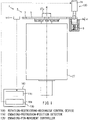
- FIG. 1 and FIG. 2 An overall configuration of a rotation restricting mechanism 1 according to a first embodiment of the present teaching is now described with reference to FIG. 1 and FIG. 2 .
- FIG. 1 is a side view of the rotation restricting mechanism 1 according to the first embodiment of the present teaching.
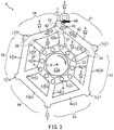
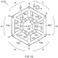
- FIG. 2 is a plan view of a rotation-restricting-mechanism-rotating-body 2 (i.e., a rotating body for the rotation restricting mechanism) according to the first embodiment of the present teaching.
- the rotation restricting mechanism 1 is a brake mechanism for restricting rotation of a motor 27 in a case where an electric current is not supplied to the motor 27 that is a rotator, or in a case where the motor 27 does not output a torque.
- the rotation restricting mechanism 1 includes the rotation-restricting-mechanism-rotating-body 2 as a rotation restricting member, an engaging pin 8 as a fixed restricting member, a solenoid 10, and a rotation-restricting-mechanism control device 100.
- the rotation restricting mechanism 1 restricts rotation of a rotation shaft 27a of the motor 27 by causing the engaging pin 8 to engage with the rotation-restricting-mechanism-rotating-body 2 that rotates integrally with the rotation shaft 27a of the motor 27.
- the rotation-restricting-mechanism-rotating-body 2 is a frame-like member rotating integrally with the rotation shaft 27a of the motor 27.
- the rotation-restricting-mechanism-rotating-body 2 is of a polygonal shape (a hexagon in an example of FIG. 2 ) when viewed in an axial direction of the rotation shaft 27a (hereinafter also referred to simply as the axial direction).
- the axial direction the rotation shaft 27a
- Portions less likely to affect the strength of the peripheral areas of the engaging protrusions 7 in the rotation-restricting-mechanism-rotating-body 2 form a polygonal shape, so that weight reduction of the rotation-restricting-mechanism-rotating-body 2 can be achieved, while suppressing degradation in strength of the rotation-restricting-mechanism-rotating-body 2.
- the moment of inertia of the rotation-restricting-mechanism-rotating-body 2 is reduced, and thereby an impact force caused when the rotation-restricting-mechanism-rotating-body 2 engages with the engaging pin 8 can be reduced.
- the rotation-restricting-mechanism-rotating-body 2 is made of stainless steel having rust-proof property, for example.
- the rotation-restricting-mechanism-rotating-body 2 is provided to the rotation shaft 27a of the motor 27, one end portion of the rotation shaft 27a serving as an output shaft and the other end portion thereof being provided with the rotation-restricting-mechanism-rotating-body 2.
- the rotation-restricting-mechanism-rotating-body 2 includes a plurality of radial-support parts 3, a plurality of first-circumferential-connecting parts 5, a plurality of second-circumferential-connecting parts 6, and the plurality of engaging protrusions 7 as the rotation-restricting members.
- Each of the radial-support parts 3 supports each of the engaging protrusions 7.
- the plurality of radial-support parts 3 are formed like a frame.
- the plurality of radial-support parts 3 are disposed in a radial pattern, with a rotation axis R that is the shaft center of the rotation shaft 27a as a radial center C. That is, the plurality of radial-support parts 3 are disposed such that all of the radial-support parts 3 intersect at the radial center C if they are extended toward the radial center C.
- the plurality of radial-support parts 3 are disposed such that all of center angles ⁇ , each made by mutually adjacent radial-support parts 3, are equal. Longitudinal directions of the plurality of radial-support parts 3 coincide with a radial direction of the rotation-restricting-mechanism-rotating-body 2.
- the rotation-restricting-mechanism-rotating-body 2 has six radial-support parts 3 disposed, for example, such that the center angles ⁇ , each made by mutually adjacent radial-support parts 3, are 60 degrees.
- the plurality of radial-support parts 3 include a first radial-support part 3a, a second radial-support part 3b, a third radial-support part 3c, a fourth radial-support part 3d, a fifth radial-support part 3e, and a sixth radial-support part 3f, which are arranged in this order in one circumferential direction (i.e., in one direction along the circumference).
- the plurality of radial-support parts 3 have the same length in the longitudinal direction (the radial direction of the rotation-restricting-mechanism-rotating-body 2), the same width in a lateral direction (the circumferential direction of the rotation-restricting-mechanism-rotating-body 2), and the same thickness in their plate-shaped members.
- the plurality of radial-support parts 3 thus having the same shape have the same stiffness and strength.
- Each of the first-circumferential-connecting parts 5 connects, out of the plurality of radial-support parts 3, mutually adjacent radial-support parts 3.
- the plurality of first-circumferential-connecting parts 5 are formed like a frame.
- the plurality of first-circumferential-connecting parts 5 have the same length in a longitudinal direction (the circumferential direction of the rotation-restricting-mechanism-rotating-body 2), the same width in a lateral direction (the radial direction of the rotation-restricting-mechanism-rotating-body 2), and the same thickness in their plate-like members.
- the plurality of first-circumferential-connecting parts 5 connect inner end portions of mutually adjacent radial-support parts 3 so as to form a polygonal shape (a hexagon in this embodiment).
- the plurality of first-circumferential-connecting parts 5 include a first first-circumferential-connecting part 5a, a second first-circumferential-connecting part 5b, a third first-circumferential-connecting part 5c, a fourth first-circumferential-connecting part 5d, a fifth first-circumferential-connecting part 5e, and a sixth first-circumferential-connecting part 5f, which are arranged in this order in the one circumferential direction.
- the first first-circumferential-connecting part 5a connects an inner end portion of the first radial-support part 3a and an inner end portion of the second radial-support part 3b.
- the second first-circumferential-connecting part 5b connects the inner end portion of the second radial-support part 3b and an inner end portion of the third radial-support part 3c.
- the third first-circumferential-connecting part 5c connects the inner end portion of the third radial-support part 3c and an inner end portion of the fourth radial-support part 3d.
- the fourth first-circumferential-connecting part 5d connects the inner end portion of the fourth radial-support part 3d and an inner end portion of the fifth radial-support part 3e.
- the fifth first-circumferential-connecting part 5e connects the inner end portion of the fifth radial-support part 3e and an inner end portion of the sixth radial-support part 3f.
- the sixth first-circumferential-connecting part 5f connects the inner end portion of the sixth radial-support part 3f and the inner end portion of the first radial-support part 3a.
- the plurality of first-circumferential-connecting parts 5 connect the inner end portions of mutually adjacent radial-support parts 3 in sequence, to thereby form a polygonal, frame-like member, connecting the plurality of radial-support parts 3.
- the plurality of first-circumferential-connecting parts 5 are provided with a plurality of fixed parts 4 connected to the rotation shaft 27a of the motor 27.
- the plurality of fixed parts 4 are fixed to the rotation shaft 27a of the motor 27 in a manner not to rotate relative thereto, so that the plurality of radial-support parts 3 connected by the plurality of first-circumferential-connecting parts 5 are more firmly fixed to the rotation shaft 27a of the motor 27. Accordingly, an external force applied to the radial-support parts 3 can be transmitted to the rotation shaft 27a of the motor 27.
- the plurality of second-circumferential-connecting parts 6 connect, out of the plurality of radial-support parts 3, mutually adjacent radial-support parts 3, and form a frame-like member.
- the plurality of second-circumferential-connecting parts 6 have the same length in a longitudinal direction (the circumferential direction of the rotation-restricting-mechanism-rotating-body 2), the same width in a lateral direction (the radial direction of the rotation-restricting-mechanism-rotating-body 2), and the same thickness in their plate-like members.
- the plurality of second-circumferential-connecting parts 6 connect outer end portions of the radial-support parts 3, which are end portions located outermost in the radial direction of the rotation-restricting-mechanism-rotating-body 2, so as to form a polygonal shape (a hexagon in this embodiment). That is, the plurality of second-circumferential-connecting parts 6 are connected to the radial-support parts 3 at radial positions different from radial positions at which the first-circumferential-connecting parts 5 are connected.
- the plurality of second-circumferential-connecting parts 6 connect the outer end portions of mutually adjacent radial-support parts 3 to thereby form a polygonal shape from a triangle to a hexagon. This can achieve further weight reduction of the rotation-restricting-mechanism-rotating-body 2, so that the moment of inertia of the rotation-restricting-mechanism-rotating-body 2 is further reduced and an impact force caused when the rotation-restricting-mechanism-rotating-body 2 engages with the engaging pin 8 is further reduced.
- the plurality of second-circumferential-connecting parts 6 thus form a polygonal shape from a triangle to a hexagon, which serves to widen an interval between the engaging protrusions 7 mutually adjacent in the circumferential direction, compared with a polygonal shape of a heptagon or having more vertices. Therefore, a possibility of offset collision between the engaging pin 8 and the engaging protrusion 7 can be further reduced.
- the offset collision refers to a state where the engaging pin 8 makes contact with an intermediate portion in the protruding direction of the engaging protrusion 7.
- the plurality of second-circumferential-connecting parts 6 include a first second-circumferential-connecting part 6a, a second second-circumferential-connecting part 6b, a third second-circumferential-connecting part 6c, a fourth second-circumferential-connecting part 6d, a fifth second-circumferential-connecting part 6e, and a sixth second-circumferential-connecting part 6f, which are arranged in this order in the one circumferential direction.
- the first second-circumferential-connecting part 6a connects an outer end portion of the first radial-support part 3a and an outer end portion of the second radial-support part 3b.
- the second second-circumferential-connecting part 6b connects the outer end portion of the second radial-support part 3b and an outer end portion of the third radial-support part 3c.
- the third second-circumferential-connecting part 6c connects the outer end portion of the third radial-support part 3c and an outer end portion of the fourth radial-support part 3d.
- the fourth second-circumferential-connecting part 6d connects the outer end portion of the fourth radial-support part 3d and an outer end portion of the fifth radial-support part 3e.
- the fifth second-circumferential-connecting part 6e connects the outer end portion of the fifth radial-support part 3e and an outer end portion of the sixth radial-support part 3f.
- the sixth second-circumferential-connecting part 6f connects the outer end portion of the sixth radial-support part 3f and the outer end portion of the first radial-support part 3a.
- the plurality of second-circumferential-connecting parts 6 connect the outer end portions of mutually adjacent radial-support parts 3 in sequence, to thereby form a polygonal, frame-like member, connecting the plurality of radial-support parts 3.
- the second-circumferential-connecting parts 6 connected to the radial-support part 3 transmit the external force to two other radial-support parts 3 adjacent to the radial-support part 3.
- Each of the engaging protrusions 7 extends outwardly in the radial direction from each of the radial-support parts 3 so as to be engageable with the engaging pin 8. That is, the plurality of engaging protrusions 7 are formed so as to extend outwardly in the radial direction from the outer end portions of the plurality of the radial-support parts 3. Thus, the plurality of engaging protrusions 7 are provided at equal intervals in the circumferential direction in the rotation-restricting-mechanism-rotating-body 2.
- each of the engaging protrusions 7 is formed so as to extend outwardly in the radial direction from an outer end in the radial direction of each of the second-circumferential-connecting parts 6, i.e., an outer end in the radial direction of the rotation-restricting-mechanism-rotating-body 2 (hereinafter referred to simply as "outer end").
- Each of the plurality of engaging protrusions 7 is supported by corresponding one of the plurality of radial-support parts 3 and corresponding ones of the plurality of second-circumferential-connecting parts 6. Any one of the plurality of engaging protrusions 7 engages with the engaging pin 8, and thereby rotation of the rotation-restricting-mechanism-rotating-body 2 can be restricted.
- the plurality of engaging protrusions 7 include a first engaging protrusion 7a, a second engaging protrusion 7b, a third engaging protrusion 7c, a fourth engaging protrusion 7d, a fifth engaging protrusion 7e, and a sixth engaging protrusion 7f, which are arranged in this order in the one circumferential direction.
- the rotation-restricting-mechanism-rotating-body 2 is formed with a plurality of sections, each separated by mutually adjacent engaging protrusions out of the plurality of engaging protrusions 7.
- a section separated by the first engaging protrusion 7a and the second engaging protrusion 7b is a first section S1.
- a section separated by the second engaging protrusion 7b and the third engaging protrusion 7c is a second section S2.
- a section separated by the third engaging protrusion 7c and the fourth engaging protrusion 7d is a third section S3.
- a section separated by the fourth engaging protrusion 7d and the fifth engaging protrusion 7e is a fourth section S4.
- a section separated by the fifth engaging protrusion 7e and the sixth engaging protrusion 7f is a fifth section S5.
- a section separated by the sixth engaging protrusion 7f and the first engaging protrusion 7a is a sixth section S6.
- an interval Ls between mutually adjacent engaging protrusions 7 out of the plurality of engaging protrusions 7 is larger than the sum of a diameter D of the columnar-shaped engaging pin 8 extending in the axial direction when viewed in the axial direction (the maximum dimension in the circumferential direction) and a width W of the engaging protrusion 7 in the circumferential direction.
- the interval Ls between mutually adjacent engaging protrusions 7 is an interval between tip end portions in the protruding directions of the mutually adjacent engaging protrusions 7.
- the rotation-restricting-mechanism-rotating-body 2 configured in this manner, the plurality of fixed parts 4 are fixed to the rotation shaft 27a of the motor 27. At that time, the rotation-restricting-mechanism-rotating-body 2 is fixed so that the radial center C coincides with the rotation axis R that is the shaft center of the rotation shaft 27a of the motor 27. Accordingly, the rotation-restricting-mechanism-rotating-body 2 is configured to rotate integrally with the rotation shaft 27a of the motor 27, with the rotation axis R of the rotation shaft 27a of the motor 27 as the rotation center.
- the engaging pin 8 serves as a member for restricting rotation of the rotation-restricting-mechanism-rotating-body 2.
- the engaging pin 8 is supported by a portion not rotating in conjunction with the motor 27 and the rotation-restricting-mechanism-rotating-body 2, such as a housing of the motor 27.
- the engaging pin 8 is made of stainless steel having rust-proof property, for example.
- the engaging pin 8 has a contact part 8a making contact with the engaging protrusions 7 of the rotation-restricting-mechanism-rotating-body 2.
- the engaging pin 8 is configured to be movable in an axial direction of the engaging pin 8.
- An axis of the engaging pin 8 is parallel to the rotation axis R of the rotation-restricting-mechanism-rotating-body 2. That is, the engaging pin 8 is configured to engage with the engaging protrusion 7 of the rotation-restricting-mechanism-rotating-body 2 by moving in the rotation axis direction of the rotation-restricting-mechanism-rotating-body 2.
- the engaging pin 8 is changed from either one of a restriction position (indicated by alternate long and two short dashed lines) or an open position (indicated by a solid line) to the other by the solenoid 10, where the restriction position is a position at which the contact part 8a makes contact with the engaging protrusion 7 of the rotation-restricting-mechanism-rotating-body 2, while the open position is a position at which the contact part 8a is free of contact with the engaging protrusion 7.
- a force is applied to the engaging pin 8 by a spring 9 to be held at the restriction position.
- the solenoid 10 generates a driving force for moving the engaging pin 8.
- the solenoid 10 is supported by the portion not rotating in conjunction with the rotation-restricting-mechanism-rotating-body 2, such as the housing of the motor 27.
- the solenoid 10 is configured to move the engaging pin 8 held at the restriction position to the open position when turned on.
- the rotation restricting mechanism 1 having such a configuration is configured to change the position of the engaging pin 8 from the open position to the restriction position by the solenoid 10, to thereby restrict a rotation angle range that is an angle range within which the rotation-restricting-mechanism-rotating-body 2 is rotatable.
- the engaging pin 8 is changed to the restriction position, so that the contact part 8a of the engaging pin 8 is located in one of the first to sixth sections S1 to S6 in the rotation-restricting-mechanism-rotating-body 2 (see FIG. 2 ).
- the rotation restricting mechanism 1 restricts, by the engaging pin 8 located in a certain section, the rotation angle range of the rotation-restricting-mechanism-rotating-body 2 from a rotation angle at which one of the engaging protrusions 7 separating the certain section makes contact with the contact part 8a of the engaging pin 8 to a rotation angle at which the other engaging protrusion 7 separating the section makes contact with the contact part 8a of the engaging pin 8.
- the rotation restricting mechanism 1 allows the rotation-restricting-mechanism-rotating-body 2 to move with respect to the engaging pin 8 in the circumferential direction between the mutually adjacent engaging protrusions 7 that separate the section.
- an interval between engaging protrusions 7 mutually adjacent in the circumferential direction in the rotation-restricting-mechanism-rotating-body 2 has a distance that enables relative movement of the engaging pin 8 in the circumferential direction between the mutually adjacent engaging protrusions 7.
- the rotation-restricting-mechanism rotating bodies 200, 2 are viewed in a direction orthogonal to the rotation axis R.
- the solid arrows indicate the direction of rotation of the rotation-restricting-mechanism rotating bodies 200, 2, while the open arrows indicate the moving direction of the engaging pin 8.
- an absolute encoder included in the actuator can detect a rotation angle within a mechanical angle of 360 degrees when the motor is stopped. That is, when the motor is stopped, the rotation-restricting-mechanism-rotating-body 2 rotating integrally with the absolute encoder is rotated to enable relative movement of the engaging pin 8 in the circumferential direction between mutually adjacent engaging protrusions 7, so that the absolute encoder detects a Z-phase signal and thereby detects an origin of the mechanical angle.
- the absolute encoder may be replaced with other encoders.
- the interval between the mutually adjacent engaging protrusions 7 is preferably smaller than the center angle ⁇ of 60 degrees made by the mutually adjacent radial-support parts 3 in the rotation-restricting-mechanism-rotating-body 2 of this embodiment.
- the rotation restricting mechanism 1 restricts the rotation angle range of the rotation-restricting-mechanism-rotating-body 2 from an angle at which the first engaging protrusion 7a makes contact with the contact part 8a of the engaging pin 8 to an angle at which the second engaging protrusion 7b makes contact with the contact part 8a of the engaging pin 8.
- the external force of the other direction, applied to the first engaging protrusion 7a, is transmitted to the first radial-support part 3a, the first second-circumferential-connecting part 6a connected to the outer end portion of the first radial-support part 3a so as to extend in the one circumferential direction, and the sixth second-circumferential-connecting part 6f connected to the outer end portion of the radial-support part 3 so as to extend in the other circumferential direction (see the hatched arrow A1, the hatched arrow A2 and the hatched arrow A3).
- first radial-support part 3a elastic deformation that causes the first radial-support part 3a to bend in the other circumferential direction occurs by the external force of the other direction applied to the first engaging protrusion 7a. At that time, a stress occurs in a connecting portion between the first radial-support part 3a and the first first-circumferential-connecting part 5a and in a connecting portion between the first radial-support part 3a and the sixth first-circumferential-connecting part 5f (see the region S1), by the elastic deformation.
- first second-circumferential-connecting part 6a so connected to the first radial-support part 3a to extend in the one circumferential direction, elastic deformation that causes the first second-circumferential-connecting part 6a to be elongated in the other circumferential direction occurs by the external force of the other direction. Furthermore, the external force of the other direction by the elastic deformation of the first second-circumferential-connecting part 6a is applied to the outer end portion of the second radial-support part 3b connected to the first second-circumferential-connecting part 6a (see the hatched arrow A2).
- elastic deformation that causes the second radial-support part 3b to bend in the other circumferential direction from the outer end portion thereof, occurs by the external force of the other direction transmitted from the first second-circumferential-connecting part 6a.
- a stress occurs in a connecting portion between the second radial-support part 3b and the first first-circumferential-connecting part 5a and in a connecting portion between the second radial-support part 3b and the second first-circumferential-connecting part 5b (see the region S3) by the elastic deformation.
- the external force of the other direction applied to the first engaging protrusion 7a from the engaging pin 8 is distributed and transmitted mainly to the first radial-support part 3a, the first second-circumferential-connecting part 6a, the second radial-support part 3b, the sixth second-circumferential-connecting part 6f and the sixth radial-support part 3f.
- the first radial-support part 3a, the first second-circumferential-connecting part 6a, the second radial-support part 3b, the sixth second-circumferential-connecting part 6f and the sixth radial-support part 3f are each elastically deformed based on their own stiffness, fixed position, connecting position with another member, magnitude of the external force of the other direction, position to which the external force of the other direction is applied, or the like.
- the plurality of radial-support parts 3 disposed in a radial pattern are connected at their inner end portions to the plurality of first-circumferential-connecting parts 5, and at their outer end portions to the plurality of second-circumferential-connecting parts 6. Accordingly, in the rotation-restricting-mechanism-rotating-body 2, the plurality of radial-support parts 3 have increased stiffness due to the plurality of first-circumferential-connecting parts 5 and the plurality of second-circumferential-connecting parts 6.
- the rotation-restricting-mechanism-rotating-body 2 has openings made by the plurality of radial-support parts 3, the plurality of first-circumferential-connecting parts 5 and the plurality of second-circumferential-connecting parts 6.
- elastic deformation occurs in the first-circumferential-connecting parts 5, the second-circumferential-connecting parts 6 and the radial-support parts 3, respectively, in accordance with their own stiffness.
- the rotation-restricting-mechanism-rotating-body 2 In the rotation-restricting-mechanism-rotating-body 2, the plurality of second-circumferential-connecting parts 6 connecting the outer end portions of mutually adjacent radial-support parts 3 deform with respect to the plurality of first-circumferential-connecting parts 5 connecting the inner end portions of the mutually adjacent radial-support parts 3. In this manner, the rotation-restricting-mechanism-rotating-body 2 absorbs an impact force caused when an external force is applied to an engaging protrusion 7, by the elastic deformation of the first-circumferential-connecting parts 5, the second-circumferential-connecting parts 6 and the radial-support parts 3.
- the rotation-restricting-mechanism-rotating-body 2 has the openings made by the plurality of radial-support parts 3, the plurality of first-circumferential-connecting parts 5 and the plurality of second-circumferential-connecting parts 6.
- a difference between the stiffness of the plurality of engaging protrusions 7, and the stiffness of the plurality of radial-support parts 3 and the plurality of second-circumferential-connecting parts 6 that are connected to the engaging protrusions 7, is smaller than a difference between the stiffness of the plurality of engaging protrusions and the stiffness of a disk-shaped portion with no openings of a rotation-restricting-mechanism-rotating-body when the rotation-restricting-mechanism-rotating-body is formed in a disk shape with no openings.
- the rotation-restricting-mechanism-rotating-body 2 has the openings as described above, and thereby absorbs an impact force caused when an external force is applied to an engaging protrusion 7, by the elastic deformation of the first-circumferential-connecting parts 5, the second-circumferential-connecting parts 6 and the radial-support parts 3.
- the impact force caused to the rotation-restricting-mechanism-rotating-body 2 by the contact with the engaging pin 8 decreases as an amount of elastic deformation increases. Therefore, when the external force is applied to the engaging protrusion 7 of the rotation-restricting-mechanism-rotating-body 2, stress concentration occurring in the engaging protrusion 7 is alleviated.
- the weight of the rotation-restricting-mechanism-rotating-body 2 is less than the weight of a rotation-restricting-mechanism-rotating-body formed in a disk shape with no openings. That is, the moment of inertia of the rotation-restricting-mechanism-rotating-body 2 having the openings is smaller than the moment of inertia of a rotation-restricting-mechanism-rotating-body having a disk shape with no openings.
- the rotation-restricting-mechanism-rotating-body 2 can suppress an impact force caused when an external force is applied to an engaging protrusion 7, compared with the case where a rotation-restricting-mechanism-rotating-body is formed in a disk shape with no openings.
- the rotation restricting mechanism 1 including the rotation-restricting-mechanism-rotating-body 2 configured in the above-described manner can be used in portions that a stronger force acts on, or enables the engagement with the engaging pin 8 in a state where rotation of the motor 27 connected to the rotation-restricting-mechanism-rotating-body 2 is not stopped. Accordingly, the rotation-restricting-mechanism-rotating-body 2 can expand the use environment of the rotation restricting mechanism 1 that restricts the rotation by the engagement of any one of the plurality of engaging protrusions 7 with the engaging pin 8.
- the rotation-restricting-mechanism control device 100 includes an engaging-protrusion-position detector 110 and an engaging-pin-movement controller 120.
- the engaging-protrusion-position detector 110 detects positions of the engaging protrusions 7 of the rotation-restricting-mechanism-rotating-body 2 based on an output from a position detecting sensor 111 when the rotation-restricting-mechanism-rotating-body 2 is rotating about the rotation axis R.
- the engaging-protrusion-position detector may be implemented by the functions of an encoder.
- the engaging-pin-movement controller 120 moves the engaging pin 8 in the axial direction.
- the engaging-pin-movement controller 120 moves the engaging pin 8 in the axial direction.
- the engaging-pin-movement controller 120 moves the engaging pin 8 in the axial direction with the force of the spring 9 by, for example, cutting off an electric current to the solenoid 10. This causes the engaging pin 8 to move to the restriction position for making contact with the engaging protrusion 7.
- the engaging-pin-movement controller 120 cuts off the electric current to the solenoid 10.
- the engaging-pin-movement controller 120, the solenoid 10 and the spring 9 constitute an engaging-pin-moving device 130.
- the engaging-pin-moving device may be constituted of elements other than the solenoid and the spring as long as the device can move the engaging pin 8 in the axial direction.
- the engaging-pin-movement controller may move the engaging pin 8 in the axial direction at another timing as long as that timing permits the engaging pin 8 to engage with an engaging protrusion 7 of the rotation-restricting-mechanism-rotating-body 2.
- the engaging-pin-moving device 130 moves the engaging pin 8 in the axial direction with respect to the rotation-restricting-mechanism-rotating-body 2, in accordance with the positions of the engaging protrusions 7 detected by the engaging-protrusion-position detector 110.
- the multi-joint-robot-arm device 11 includes the rotation restricting mechanism 1 having the rotation-restricting-mechanism-rotating-body 2 according to the first embodiment of the present teaching.
- FIG. 5 is a schematic view of the multi-joint-robot-arm device 11 according to the second embodiment of the present teaching.
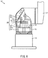
- FIG. 6 is a schematic view of an S-axis rotary joint 14 of a multi-joint-robot-arm 12 according to the second embodiment of the present teaching.
- the multi-joint-robot-arm device 11 includes the multi-joint robot arm 12 and a multi-joint-robot-arm control device 30.
- the multi-joint robot arm 12 is a robot arm of a serial link mechanism in which links are connected in series from a base end to a tip end via rotary joints of one degree of freedom.
- the multi-joint robot arm 12 is, for example, a six-axis vertical multi-joint robot arm.
- the multi-joint robot arm 12 is provided, for example, on a base of a manufacturing device or a remote operation vehicle that can be remotely operated.
- an S-axis rotary joint 14, an L-axis rotary joint 16, a U-axis rotary joint 18, an R-axis rotary joint 20, a B-axis rotary joint 22, and a T-axis rotary joint 24 are connected in series in this order from a base end portion via cases and links.
- Each axis is configured to be rotatable by a speed reducer 25 and an actuator 26.
- Each of the S-axis rotary joint 14, the L-axis rotary joint 16, the U-axis rotary joint 18, the R-axis rotary joint 20, the B-axis rotary joint 22, and the T-axis rotary joint 24 includes the speed reducer 25 and the actuator 26 (see FIG. 6 ).
- the multi-joint robot arm 12 is controlled by the multi-joint-robot-arm control device 30.
- the multi-joint robot arm 12 acquires a control signal output from the multi-joint-robot-arm control device 30 by a driving unit 29 included in the actuator 26 of each axis.
- the multi-joint robot arm 12 transmits, to the multi-joint-robot-arm control device 30, information related to an output of the actuator 26 and information output from an absolute encoder 28, of each axis.
- the S-axis rotary joint 14 is a rotary joint that turns the entire multi-joint robot arm 12.
- the S-axis rotary joint 14 is provided in a case 15 for S and L axes of the multi-joint robot arm 12.
- a base member 13 is fixed to an output shaft of the S-axis rotary joint 14.
- the base member 13 is fixed to an installation surface of the multi-joint robot arm 12.
- the S-axis rotary joint 14 is disposed such that an axis line of the S-axis rotary joint 14 extends in a direction perpendicular to the installation surface of the multi-joint robot arm 12.
- the L-axis rotary joint 16 is a rotary joint that causes a lower arm link 17 to swing.
- the L-axis rotary joint 16 is provided in the case 15 for S and L axes.
- the L-axis rotary joint 16 is disposed such that an axis line of the L-axis rotary joint 16 extends in a direction perpendicular to the axis line of the S-axis rotary joint 14.
- One end portion of the lower arm link 17 is fixed to an output shaft of the L-axis rotary joint 16.
- the U-axis rotary joint 18 is a rotary joint that causes an upper arm link 21 to swing.
- the U-axis rotary joint 18 is provided in a case 19 for U and R axes of the multi-joint robot arm 12.
- An output shaft of the U-axis rotary joint 18 is fixed to the other end portion of the lower arm link 17.
- the U-axis rotary joint 18 is disposed such that an axis line of the U-axis rotary joint 18 extends in a direction parallel to the axis line of the L-axis rotary joint 16.
- the R-axis rotary joint 20 is a rotary joint that causes the upper arm link 21 to rotate.
- the R-axis rotary joint 20 is provided in the case 19 for U and R axes.
- the R-axis rotary joint 20 is disposed such that an axis line of the R-axis rotary joint 20 extends in a direction perpendicular to the axis line of the U-axis rotary joint 18.
- One end portion of the upper arm link 21 is fixed to an output shaft of the R-axis rotary joint 20.
- the B-axis rotary joint 22 is a rotary joint that causes the T-axis rotary joint 24 to swing.
- the B-axis rotary joint 22 is provided in a case 23 for B and T axes of the multi-joint robot arm 12.
- An output shaft of the B-axis rotary joint 22 is fixed to the other end portion of the upper arm link 21.
- the B-axis rotary joint 22 is disposed such that an axis line of the B-axis rotary joint 22 extends in a direction perpendicular to the axis line of the R-axis rotary joint 20.
- the T-axis rotary joint 24 is a rotary joint that causes an unillustrated end effector to rotate.
- the T-axis rotary joint 24 is provided in the case 23 for B and T axes.
- the T-axis rotary joint 24 is disposed such that an axis line of the T-axis rotary joint 24 extends in a direction perpendicular to the axis line of the B-axis rotary joint 22.
- An output shaft of the T-axis rotary joint 24 includes an end effector attachment portion.
- the multi-joint robot arm 12 configured in the above-described manner has three translational degrees of freedom in an X axis, a Y axis, and a Z axis and three rotational degrees of freedom around the X axis, the Y axis, and the Z axis, that is, six degrees of freedom in total, by the speed reducer 25 and the actuator 26 of each axis. Accordingly, the multi-joint robot arm 12 can move the output shaft of the T axis to an arbitrary position and also can be made to have an arbitrary posture in a movable space of the multi-joint robot arm 12.
- the speed reducer 25 and the actuator 26 of each of the S axis, the L axis, the U axis, the R axis, the B axis, and the T axis is a driving unit that causes the output shaft to rotate in accordance with a control signal from the multi-joint-robot-arm control device 30.
- the speed reducer 25 and the actuator 26 are disposed in the case 15, the case 19, and the case 23 (see FIG. 5 ) of the multi-joint robot arm 12.
- the speed reducers 25 and the actuators 26 of the axes, respectively, have the same configuration, and therefore, the S-axis rotary joint 14 will be described below.
- the speed reducer 25 of the S-axis rotary joint 14 causes the output shaft to rotate in a state where rotation speed of the output shaft is decelerated with respect to rotation speed of an input shaft and generates, as an output torque of the output shaft, an output torque inversely proportional to the deceleration.
- the speed reducer 25 is provided in the case 15 of the multi-joint robot arm 12.
- a housing of the speed reducer 25 is fixed to inside of the case 15 of the multi-joint robot arm 12.
- An output shaft of the speed reducer 25 is fixed to the base member 13.
- the actuator 26 of the S-axis rotary joint 14 includes the speed reducer 25, the motor 27, the rotation restricting mechanism 1, the absolute encoder 28, and the driving unit 29 that is a computer for controlling the motor 27.
- the speed reducer 25, the motor 27, the rotation restricting mechanism 1, the absolute encoder 28 and the driving unit 29 are disposed in the case 15 of the multi-joint robot arm 12.
- the motor 27 included in the actuator 26 is a power generation source.
- the motor 27 is a so-called inner rotor motor 27 in which a rotor is disposed so as to be rotatable in a cylindrical stator.
- the rotation shaft 27a extending along the shaft center is fixed to the rotor in a state where the rotation shaft 27a passes therethrough in the axial direction.
- the motor 27 is fixed to one end portion to which power is input in a case of the speed reducer 25.
- One end portion of the rotation shaft 27a is connected to an input shaft of the speed reducer 25 as an output shaft of the motor 27.
- the rotation restricting mechanism 1 included in the actuator 26 restricts rotation of the rotation shaft 27a in the motor 27.
- the rotation restricting mechanism 1 is provided in the other end portion of the rotation shaft 27a.
- the rotation restricting mechanism 1 limits rotation of the rotation shaft 27a of the motor 27 by mechanical engagement.
- the rotation restricting mechanism 1 may be provided in the one end portion of the rotation shaft 27a.
- the rotation restricting mechanism 1 includes the rotation-restricting-mechanism-rotating-body 2 (see FIG. 2 ), the engaging pin 8 and the solenoid 10.
- the rotation restricting mechanism 1 restricts rotation of the rotation shaft 27a by causing the engaging pin 8 to engage with the rotation-restricting-mechanism-rotating-body 2 that rotates integrally with the rotation shaft 27a of the motor 27 ( FIG. 1 ).
- the absolute encoder 28 included in the actuator 26 detects a rotation angle of the rotation shaft 27a in the motor 27 within a mechanical angle of 360 degrees.
- the absolute encoder 28 transmits an AB-phase signal used for detecting a rotation angle within a mechanical angle of 360 degrees and a Z-phase signal used for detecting an origin of the mechanical angle to the driving unit 29 and the multi-joint-robot-arm control device 30 (see FIG. 2 ).
- the absolute encoder 28 is provided in the other end portion of the rotation shaft 27a in the motor 27. That is, the rotation restricting mechanism 1 and the absolute encoder 28 rotate integrally with the rotation shaft 27a of the motor 27.
- the driving unit 29 provided in the actuator 26 controls a drive electric current supplied to the motor 27.
- the driving unit 29 is, for example, a computer.
- the driving unit 29 is provided in the case 15 of the multi-joint robot arm 12.
- the driving unit 29 supplies the motor 27 with an electric current in accordance with the control signal from the multi-joint-robot-arm control device 30.
- the driving unit 29 acquires the AB-phase signal and the Z-phase signal of the absolute encoder 28 as feedback pulses.
- the driving unit 29 controls the motor 27 by feedback control in which an electric current in accordance with a difference of a feedback pulse with respect to a command pulse is supplied to the motor 27.
- the driving unit 29 also controls the solenoid 10 of the rotation restricting mechanism 1.
- the speed reducer 25, the motor 27, the rotation restricting mechanism 1 and the absolute encoder 28 are integrally configured.
- the multi-joint robot arm 12 is configured as an electromechanical integrated configuration in which the speed reducer 25, the actuator 26, and the driving unit 29 are disposed in the case 15 of the multi-joint robot arm 12.
- the output shaft of the speed reducer 25 rotates due to rotation of the motor 27, and thus, the case 15 and the actuator 26, of the multi-joint robot arm 12, are caused to integrally rotate.
- the multi-joint robot-arm control device 30 is a device that controls the multi-joint robot arm 12.
- the multi-joint-robot-arm control device 30 may be substantially configured such that a CPU, a ROM, a RAM, a HDD, and the like are connected via a bus and, alternatively, may be configured of a one-chip LSI or the like.
- Various types of programs or data are stored in the multi-joint-robot-arm control device 30 in order to control an operation of the multi-joint robot arm 12.
- the multi-joint-robot-arm control device 30 is connected to each of the driving units 29 included in the S-axis rotary joint 14, the L-axis rotary joint 16, the U-axis rotary joint 18, the R-axis rotary joint 20, the B-axis rotary joint 22, and the T-axis rotary joint 24.
- the multi-joint-robot-arm control device 30 can transmit a control signal to the driving unit 29 of each axis.
- the multi-joint-robot-arm control device 30 can acquire rotation position information of the motor 27 from the actuator 26 and the driving unit 29 of each axis.
- the rotation-restricting-mechanism-rotating-body 2 can be used to restrict rotation of the actuator 26 for the S-axis rotary joint 14 that the strongest force acts on, out of the rotary joints of respective axes.
- the multi-joint-robot-arm device 11 uses the rotation-restricting-mechanism-rotating-body 2, and thereby can restrict rotation of the motor 27 in a state where the rotation of the motor 27 is not stopped, without loss of power supply, or the like. Accordingly, the rotation-restricting-mechanism-rotating-body 2 can expand the use environment of the rotation restricting mechanism 1 that restricts the rotation by the engagement of any one of the plurality of engaging protrusions 7 with the engaging pin 8.
- the operation of the rotation restricting mechanism 1 includes a first operation, a second operation and a third operation.
- the first operation is an operation for causing the engaging pin 8 to engage with an engaging protrusion 7 of the rotation-restricting-mechanism-rotating-body 2 after rotation of the rotation shaft 27a is stopped by a regeneration brake (not shown) included in the motor 27.
- the second operation is an operation for converting energy of rotating bodies including the rotation-restricting-mechanism-rotating-body 2 into heat by an unillustrated short brake, and thereafter causing the engaging pin 8 to engage with the engaging protrusion 7 of the rotation-restricting-mechanism-rotating-body 2 in a state where the rotation-restricting-mechanism-rotating-body 2 is rotating.
- the third operation is an operation for causing the engaging pin 8 to engage with the engaging protrusion 7 of the rotation-restricting-mechanism-rotating-body 2 in a state where the rotation-restricting-mechanism-rotating-body 2 is rotating.
- the rotation restricting mechanism when it is in operation, performs one of the first operation, the second operation or the third operation in accordance with, for example, the functional state of the multi-joint-robot-arm device 11.
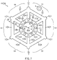
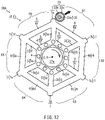
- FIG. 7 is a plan view of a rotation-restricting-mechanism-rotating-body 2B according to the third embodiment of the present teaching.
- the rotation restricting mechanism 1B includes the rotation-restricting-mechanism-rotating-body 2B, the engaging pin 8 and the solenoid 10 (see FIG. 1 ).
- the rotation restricting mechanism 1B restricts rotation of the rotation shaft 27a by causing the engaging pin 8 to engage with the rotation-restricting-mechanism-rotating-body 2B that rotates integrally with the rotation shaft 27a of the motor 27 (see FIG. 1 ).
- the rotation-restricting-mechanism-rotating-body 2B is a frame-like member rotating integrally with the rotation shaft 27a of the motor 27.
- the rotation-restricting-mechanism-rotating-body 2B is of a polygonal shape (a hexagon in an example of FIG. 7 ) when viewed in the axial direction of the rotation shaft 27a.
- the rotation-restricting-mechanism-rotating-body 2B includes the plurality of beam-like radial-support parts 3, the plurality of beam-like first-circumferential-connecting parts 5, the plurality of beam-like second-circumferential-connecting parts 6, and the plurality of engaging protrusions 7.
- the plurality of radial-support parts 3 are disposed in a radial pattern, with the rotation axis R that is the shaft center of the rotation shaft 27a as the radial center C. In addition, the plurality of radial-support parts 3 are disposed such that all of the center angles ⁇ each made by mutually adjacent radial-support parts 3 are equal. The longitudinal directions of the plurality of radial-support parts 3 coincide with the radial direction of the rotation-restricting-mechanism-rotating-body 2.
- Each of the first-circumferential-connecting parts 5 has a width W1 in the lateral direction (in the radial direction of the rotation-restricting-mechanism-rotating-body 2B), and is formed like a beam.
- Each of the first-circumferential-connecting parts 5 is connected to mutually adjacent radial-support parts 3 over a range of the width W1 in the longitudinal direction of each of the mutually adjacent radial-support parts 3 from its inner end.
- Each of the second-circumferential-connecting parts 6 has a width W2 in the lateral direction (in the radial direction of the rotation-restricting-mechanism-rotating-body 2B), and is formed like a beam.
- Each of the second-circumferential-connecting parts 6 is connected to mutually adjacent radial-support parts 3 over a range of the width W2 in the longitudinal direction of each of the mutually adjacent radial-support parts 3 from its outer end.
- the width W1 of each of the first-circumferential-connecting parts 5 and the width W2 of each of the second-circumferential-connecting parts 6 are less than an interval W3 between an outer edge of the first-circumferential-connecting part 5 and an inner edge of the second-circumferential-connecting part 6. That is, the first-circumferential-connecting part 5 is connected to the inner end portion of each of the radial-support parts 3 over the range of the width W1 less than a range of the radial interval W3 to which nothing is connected in the radial-support part 3.
- the second-circumferential-connecting part 6 is connected to the outer end portion of each of the radial-support parts 3 over the range of the width W2 less than the range of the radial interval W3.
- the stiffness in the range of the radial interval W3 is less than the stiffness in the range of the width W1 to which the first-circumferential-connecting part 5 is connected and the stiffness in the range of the width W2 to which the second-circumferential-connecting part 6 is connected.
- elastic deformation in the range of the interval W3 is more likely to occur as the range of the interval W3 becomes larger than the width W1 and the width W2. This reduces the stresses in the range of the width W1 and the range of the width W2 of the radial-support part 3 caused by the elastic deformation.
- the external force of the other direction, applied to the engaging protrusion 7, is transmitted to the radial-support part 3, the second-circumferential-connecting part 6 connected to the outer end portion of the radial-support part 3 so as to extend in the one circumferential direction, and the second-circumferential-connecting part 6 connected to the outer end portion of the radial-support part 3 so as to extend in the other circumferential direction (see the hatched arrow A1, the hatched arrow A2 and the hatched arrow A3 in FIG. 3 ).
- elastic deformation that causes the radial-support part 3 to bend in the other circumferential direction from the outer end portion thereof occurs by the external force of the other direction.
- larger elastic deformation occurs in the range of the interval W3 than in the range of the width W1 in the inner end portion thereof and the range of the width W2 in the outer end portion thereof, where the range of the interval W3 has less stiffness than the range of the width W1 and the range of the width W2, and is larger than the range of the width W1 and the range of the width W2.
- the rotation-restricting-mechanism-rotating-body 2B can expand the use environment of the rotation restricting mechanism 1B that restricts rotation by the engagement of the plurality of engaging protrusions 7.
- FIG. 8 is a side view of the rotation restricting mechanism 1C according to the fourth embodiment of the present teaching.
- FIG. 9 is a plan view of a rotation-restricting-mechanism-rotating-body 2C according to the fourth embodiment of the present teaching.
- the rotation restricting mechanism 1C includes the rotation-restricting-mechanism-rotating-body 2C, the engaging pin 8 and the solenoid 10.
- the rotation restricting mechanism 1C restricts rotation of the rotation shaft 27a of the motor 27 by causing the engaging pin 8 to engage with the rotation-restricting-mechanism-rotating-body 2C that rotates integrally with the rotation shaft 27a of the motor 27.
- the rotation-restricting-mechanism-rotating-body 2C is a beam-like member rotating integrally with the rotation shaft 27a of the motor 27.
- the rotation-restricting-mechanism-rotating-body 2B is of a polygonal shape (a hexagon in an example of FIG. 9 ) when viewed in the axial direction of the rotation shaft 27a.
- the rotation-restricting-mechanism-rotating-body 2C includes the plurality of beam-like radial-support parts 3, the plurality of beam-like first-circumferential-connecting parts 5, the plurality of beam-like second-circumferential-connecting parts 6, and plurality of engaging protrusions 31.
- the plurality of engaging protrusions 31 extend in the axial direction of the rotation axis R of the rotation-restricting-mechanism-rotating-body 2C from the respective radial-support parts 3 so as to be engageable with the engaging pin 8.
- the plurality of engaging protrusions 31 are formed so as to extend from the outer end portions of the plurality of radial-support parts 3, in the direction of the other end portion of the rotation shaft 27a of the motor 27, the shaft center of the rotation shaft 27a being coincident with the rotation axis R.
- the plurality of engaging protrusions 31 are provided at equal intervals in the circumferential direction in the rotation-restricting-mechanism-rotating-body 2C.
- the plurality of engaging portions 31 are respectively bent in the direction of the other end portion of the rotation shaft 27a of the motor 27. Furthermore, the plurality of engaging protrusions 31 are formed so as to extend in the axial direction of the rotation axis R of the rotation-restricting-mechanism-rotating-body 2C from the outer ends of the plurality of second-circumferential-connecting parts 6. The engaging protrusions 31 extend in the direction along the rotation axis R so as to be capable of engaging with the engaging pin 8 and thereby restricting rotation of the rotation-restricting-mechanism-rotating-body 2C.
- the plurality of engaging protrusions 31 extend in the axial direction of the rotation axis R of the rotation-restricting-mechanism-rotating-body 2C as described above, so that a maximum radius of the rotation-restricting-mechanism-rotating-body 2C is a distance from the rotation axis R of the rotation-restricting-mechanism-rotating-body 2C to the outer end of each of the second-circumferential-connecting parts 6. Accordingly, the maximum radius of the rotation-restricting-mechanism-rotating-body 2C is less than that in a configuration where a plurality of engaging protrusions extend in the radial direction.
- the rotation-restricting-mechanism-rotating-body 2C can also enhance design flexibility of the engaging pin 8 that engages with any one of the plurality of engaging protrusions 31. Accordingly, the rotation-restricting-mechanism-rotating-body 2C can expand the use environment of the rotation restricting mechanism 1C that restricts rotation by the engagement of the plurality of engaging protrusions 31.
- the plurality of engaging protrusions 31 extend in the axial direction of the rotation axis R of the rotation-restricting-mechanism-rotating-body 2C, so that, as compared with a configuration where engaging protrusions extend in the radial direction of a rotation-restricting-mechanism-rotating-body, it is possible to provide a larger contact surface contacted by the engaging pin 8 in the rotation-restricting-mechanism-rotating-body 2C, while reducing a thickness of the rotation-restricting-mechanism-rotating-body 2C. This can reduce stress concentration in the rotation-restricting-mechanism-rotating-body 2C caused when the rotation-restricting-mechanism-rotating-body 2C engages with the engaging pin 8.
- the configuration of the rotation-restricting-mechanism-rotating-body 2C except the engaging protrusions 31 is similar to that of the rotation-restricting-mechanism-rotating-body 2 according to the first embodiment.
- the configuration of the rotation-restricting-mechanism-rotating-body 2C except the engaging protrusions 31 can achieve similar effect to that of the rotation-restricting-mechanism-rotating-body 2 according to the first embodiment.
- the plurality of radial-support parts 3 are bent in the axial direction of the rotation axis R of the rotation-restricting-mechanism-rotating-body 2D to thereby form the plurality of engaging protrusions 31.
- the configuration of the rotation-restricting-mechanism-rotating-body is not limited to the above-described configuration.
- FIG. 10 is a plan view of a rotation-restricting-mechanism-rotating-body 2D according to a modification of the fourth embodiment of the present teaching.
- the rotation-restricting-mechanism-rotating-body 2D of a rotation restricting mechanism 1D has a plurality of columnar-shaped rotary engaging pins 32 in the outer end portions of the plurality of radial-support parts 3, for example, as engaging protrusions.
- the plurality of rotary engaging pins 32 are provided such that they extend in one direction or the other direction along the rotation axis R of the rotation-restricting-mechanism-rotating-body 2D from the outer end portions of the plurality of radial-support parts 3.
- the plurality of rotary engaging pins 32 are provided at equal intervals in the circumferential direction in the rotation-restricting-mechanism-rotating-body 2D.
- FIG. 11 is a side view of the actuator including the rotation restricting mechanism IE according to the fifth embodiment of the present teaching.
- FIG. 12 is a plan view illustrating an elastic deformation state of an engaging pin 33 when the engaging pin 33 makes contact with the rotation-restricting-mechanism-rotating-body 2 of the actuator 26A according to the fifth embodiment of the present teaching.
- the actuator 26A includes the motor 27, the rotation restricting mechanism IE, the absolute encoder, and the driving unit that is a computer for controlling the motor 27.
- the configurations of the absolute encoder and the driving unit are similar to those shown in FIG. 6 .
- the rotation restricting mechanism IE restricts rotation of the rotation shaft 27a of the motor 27.
- the rotation restricting mechanism IE limits the rotation of the rotation shaft 27a of the motor 27 by mechanical engagement.
- the rotation restricting mechanism 1E includes the rotation-restricting-mechanism-rotating-body 2, the engaging pin 33 and the solenoid 10.
- the rotation restricting mechanism 1E restricts the rotation of the rotation shaft 27a of the motor 27 by causing the engaging pin 33 to engage with the rotation-restricting-mechanism-rotating-body 2 that rotates integrally with the rotation shaft 27a of the motor 27.
- the engaging pin 33 is a member for restricting rotation of the rotation-restricting-mechanism-rotating-body 2.
- the engaging pin 33 is supported by a portion not rotating in conjunction with the motor 27 and the rotation-restricting-mechanism-rotating-body 2, such as the housing of the motor 27.
- the engaging pin 33 includes a base 33a, an impact reducer 33b, and a contact part 33c.
- the base 33a is a member for supporting the impact reducer 33b and the contact part 33c.
- the base 33a is formed in a columnar shape, for example.
- the solenoid 10 is disposed at one end portion in the axial direction of the base 33a.
- the spring 9 is disposed at the other end portion in the axial direction of the base 33a.
- the base 33a is configured to be movable in the axial direction.
- the base 33a is disposed so that its axis is parallel to the rotation axis R of the rotation-restricting-mechanism-rotating-body 2.
- the impact reducer 33b is a member for absorbing an impact force transmitted via the contact part 33c.
- the impact reducer 33b is made of synthetic rubber that is an elastic body, or the like.
- the impact reducer 33b is formed in a hollow cylindrical shape, for example, to allow the base 33a to be inserted therein.
- the impact reducer 33b is provided on an outer circumferential surface of the base 33a.
- the impact reducer 33b has a thickness with which an impact force applied by the contact of an engaging protrusion 7 with the contact part 33c can be absorbed to some degree.
- the contact part 33c is a member for making contact with the plurality of engaging protrusions 7 of the rotation-restricting-mechanism-rotating-body 2.
- the contact part 33c is formed in a hollow cylindrical shape, for example, to allow the impact reducer 33b to be inserted therein.
- the contact part 33c is provided so as to cover an outer circumferential surface of the impact reducer 33b. That is, the contact part 33c prevents direct contact of the engaging protrusions 7 with the impact reducer 33b to thereby protect the impact reducer 33b.
- the engaging pin 33 with the configuration as described above is configured such that the base 33a, the impact reducer 33b and the contact part 33c can be moved integrally in the axial direction by the solenoid 10 and the spring 9.
- the engaging pin 33 is changed from either one of a restriction position (indicated by alternate long and two short dashed lines) or an open position (indicated by a solid line) to the other by the solenoid 10, where the restriction position is a position at which the contact part 33c makes contact with the plurality of engaging protrusions 7 of the rotation-restricting-mechanism-rotating-body 2, while the open position is a position at which the contact part 33c is free of contact with the engaging protrusions 7.
- a force is applied in the axial direction to the engaging pin 33 by the spring 9 to be held at the restriction position.
- the rotation restricting mechanism IE restricts a rotation angle range of the rotation-restricting-mechanism-rotating-body 2 from an angle at which one engaging protrusion 7 makes contact with the contact part 33c of the engaging pin 8 to an angle at which another engaging protrusion 7 adjacent to the one engaging protrusion 7 makes contact with the contact part 33c.
- the contact part 33c of the engaging pin 33 makes contact with the first engaging protrusion 7a of the rotation-restricting-mechanism-rotating-body 2. This causes an impact force to be applied to the contact surface 33c from the first engaging protrusion 7a.
- the impact reducer 33b is elastically deformed between the base 33a and the contact part 33c (see the black-filled arrow).
- the engaging pin 33 absorbs the impact force received from the first engaging protrusion 7a, as well as reduces an amount of elastic deformation of the first engaging protrusion 7a as compared with a case where no impact reducer 33b is provided. Accordingly, the rotation restricting mechanism IE suppresses stresses occurring in the rotation-restricting-mechanism-rotating-body 2 and the engaging pin 33 by the engaging pin 33 having the impact reducer 33b.
- the actuator 26A including the rotation restricting mechanism IE restricts rotation of the rotation-restricting-mechanism-rotating-body 2 of the rotation restricting mechanism IE, thereby restricting rotation of the rotation shaft 27a to which the rotation-restricting-mechanism-rotating-body 2 is connected. At that time, the stresses occurring in the engaging pin 33 and the rotation-restricting-mechanism-rotating-body 2 are suppressed.
- the actuator 26A can be used as an actuator for the S-axis rotary joint 14 that the strongest force acts on, out of the rotary joints of respective axes in the multi-joint-robot-arm device 11. Accordingly, the actuator 26A can expand the use environment of the rotation restricting mechanism 1E that restricts rotation by the engagement of the plurality of engaging protrusions 7.
- the impact reducer 33b provided to the engaging pin 33 between the contact part 33c and the base 33a as in this embodiment can also reduce noise and vibration caused by the engagement of the rotation-restricting-mechanism-rotating-body 2 with the engaging pin 33.
- an interval between mutually adjacent engaging protrusions 7 out of the plurality of engaging protrusions 7 in this embodiment is also larger than the sum of a diameter of the columnar-shaped engaging pin 33 extending in the axial direction when viewed in the axial direction (the maximum dimension in the circumferential direction) and a width of the engaging protrusion 7 in the circumferential direction.
- FIG. 13 is a plan view illustrating an elastic deformation state of a rotation contact part 34b when the engaging pin 8 makes contact with a rotation-restriction-mechanism rotating body 2F in the actuator according to the sixth embodiment of the present teaching.
- the actuator 26B includes the motor, the rotation restricting mechanism 1F, the absolute encoder, and the driving unit that is a computer for controlling the motor 27.
- the configurations of the motor, the absolute encoder and the driving unit are similar to those shown in FIG. 6 .
- the rotation restricting mechanism 1F restricts rotation of the rotation shaft 27a of the motor 27.
- the rotation restricting mechanism 1F includes the rotation-restricting-mechanism-rotating-body 2F, the engaging pin 8 and the solenoid.
- the configuration of the solenoid is similar to that shown in FIG. 6 .
- the plurality of engaging protrusions 7 of the rotation-restricting-mechanism-rotating-body 2F have a plurality of rotation impact reducers 34a and a plurality of rotation contact parts 34b.
- the plurality of rotation impact reducers 34a are members for absorbing impact forces transmitted from the rotation contact parts 34b.
- the plurality of rotation impact reducers 34a are made of synthetic rubber that is an elastic body, or the like.
- Each of the rotation impact reducers 34a is provided to each of the engaging protrusions 7.
- the plurality of rotation impact reducers 34a are provided so as to cover the plurality of engaging protrusions 7.
- Each of the rotation impact reducers 34a has a thickness with which an impact force applied by the engaging pin 8 can be absorbed to some degree.
- the plurality of rotation contact parts 34b make contact with the contact part 33c of the engaging pin 8.
- the plurality of rotation contact parts 34b are provided so as to cover the plurality of rotation impact reducers 34a. That is, the rotation contact parts 34b prevent the contact of the engaging pin 8 with the rotation impact reducers 34a to thereby protect the rotation impact reducers 34a.
- the engaging pin 8 makes contact with the rotation contact part 34b provided on the first engaging protrusion 7a. This causes an impact force to be applied to the rotation contact part 34b from the first engaging pin 8.
- the rotation impact reducer 34a is elastically deformed (see the black-filled arrow), so that the impact force applied from the engaging pin 8 is reduced. Accordingly, the rotation restricting mechanism 1F suppresses the stresses occurring in the rotation-restricting-mechanism-rotating-body 2F and the engaging pin 8 by the rotation impact reducer 34a.
- the actuator 26B including the rotation restricting mechanism 1F, the stresses occurring in the engaging pin 8 and the rotation-restricting-mechanism-rotating-body 2F are suppressed.
- the actuator 26B can expand the use environment of the rotation restricting mechanism 1F that restricts rotation by the engagement of the engaging protrusions 7.
- the rotation impact reducers 34a provided to the engaging protrusions 7 of the rotation-restricting-mechanism-rotating-body 2F, as in this embodiment, can also reduce noise and vibration caused by the engagement of the rotation-restricting-mechanism-rotating-body 2F with the engaging pin 8.
- the configuration of the rotation-restricting-mechanism-rotating-body 2F, except the rotation impact reducers 34a and the rotation contact parts 34b, is similar to that of the rotation-restricting-mechanism-rotating-body 2 according to the first embodiment.
- the configuration of the rotation-restricting-mechanism-rotating-body 2F, except the rotation impact reducers 34a and the rotation contact parts 34b, can achieve similar effect to that of the rotation-restricting-mechanism-rotating-body 2 according to the first embodiment.
- the multi-joint robot arm 12 that is a six-axis vertical multi-join robot arm is configured, as an example, such that the S-axis rotary joint 14, the L-axis rotary joint 16, the U-axis rotary joint 18, the R-axis rotary joint 20, the B-axis rotary joint 22, and the T-axis rotary joint 24 are connected in series via links, but is not limited thereto.
- the number of connected axes a connection order in which motor units M of the axes are connected, axial directions when the axes are connected, or the like, any other configuration than that of the second embodiment described above may be used if the configuration can function as a multi-joint robot arm.
- the actuator 26 is used as the rotary joint of each axis of the multi-joint robot arm 12.
- a configuration of the actuator 26 is not limited to the configurations of the above-described embodiments.
- the actuator 26 may be applied to a device, such as an XY table, a vertical conveyance device, or the like, that requires position control, or the like.
- the actuator 26 may not include the speed reducer 25.
- the actuator 26 is configured as an electromechanical integrated configuration in which the motor 27, the speed reducer 25, the absolute encoder 28, and the driving unit 29 are provided in each of the case 15, the case 19, and the case 23 of the multi-joint robot arm 12.
- the configuration of the actuator 26 is not limited to that of the above-described second embodiment.
- the actuator may be configured such that the driving unit is disposed outside the cases of the multi-joint robot arm.
- the rotation-restricting-mechanism-rotating-body 2 the rotation-restricting-mechanism-rotating-body 2B, the rotation-restricting-mechanism-rotating-body 2C, the rotation-restricting-mechanism-rotating-body 2D, and the rotation-restricting-mechanism-rotating-body 2F (hereinafter referred to simply as "the respective rotation-restricting-mechanism rotating bodies") are made of stainless steel.
- the respective rotation-restricting-mechanism rotating bodies may be made of other materials, such as iron subjected to rust-poof treatment, aluminum alloys, ceramics, carbon fiber reinforced plastics, or glass fiber reinforced plastics as long as they are materials that have rust-proof property and can resist an impact force received from the engaging pin 8.
- the respective rotation-restricting-mechanism rotating bodies have a hexagonal shape when viewed in the axial direction of the rotation shaft 27a.
- the respective rotation-restricting-mechanism rotating bodies may have other shapes as long as they are a polygon.
- the six engaging protrusions 7, 31 or the rotary engaging pins 32 in the respective rotation-restricting-mechanism rotating bodies are formed at equal intervals in the circumferential direction.
- the configurations of the respective rotation-restricting-mechanism rotating bodies are not limited to the configurations of the above-described embodiments.
- the number of the engaging protrusions or the rotary engaging pins may be numbers other than six.
- the plurality of engaging protrusions or the plurality of rotary engaging pins may not be formed at equal intervals in the circumferential direction.
- the first-circumferential-connecting parts 5 and the second-circumferential-connecting parts 6, in the respective rotation-restricting-mechanism rotating bodies connect mutually adjacent radial-support parts 3.
- the configurations of the respective rotation-restricting-mechanism rotating bodies are not limited to the above-described configurations.
- the respective rotation-restricting-mechanism rotating bodies may further include the third or more circumferential-connecting parts to connect mutually adjacent radial-support parts 3.
- the plurality of radial-support parts 3, in the respective rotation-restricting-mechanism rotating bodies are disposed in a radial pattern around one point as the radial center C.
- the configurations of the respective rotation-restricting-mechanism rotating bodies are not limited to the above-described configurations.
- the plurality of radial-support parts may be divided into a plurality of groups having different radial centers, and radial-support parts of each group may be disposed in a radial pattern around its radial center.
- the plurality of radial-support parts 3, in the respective rotation-restricting-mechanism rotating bodies are disposed in a radial pattern with the center angles ⁇ each made by mutually adjacent radial-support parts 3 at 60 degrees.
- the configurations of the respective rotation-restricting-mechanism rotating bodies are not limited to the above-described configurations.
- the center angles each made by mutually adjacent radial-support parts are not limited to 60 degrees as long as the plurality of radial-support parts are disposed in a radial pattern.
- the first-circumferential-connecting parts in the respective rotation-restricting-mechanism rotating bodies, connect mutually adjacent radial-support parts 3 so as to form a polygonal shape.
- the first-circumferential-connecting parts may connect mutually adjacent radial-support parts so as to form an annular shape.
- the rotation restricting mechanism 1, the rotation restricting mechanism 1B, the rotation restricting mechanism 1C, the rotation restricting mechanism ID, the rotation restricting mechanism IE, and the rotation restricting mechanism 1F are configured such that the engaging pin 8 or 33 engages with the engaging protrusions 7 of the respective rotation restricting mechanisms.
- the configurations of the respective rotation restricting mechanisms are not limited to the above-described configurations.
- the engaging pin 8 or 33 may engage with the plurality of radial-support parts 3 between the plurality of first-circumferential-connecting parts 5 and the plurality of second-circumferential-connecting parts 6.
- the engaging pins 8 and 33 are made of stainless steel.
- the configurations of the engaging pins 8 and 33 are not limited to the configurations of the above-described embodiments.
- the engaging pins 8 and 33 may be made of other materials, such as iron subjected to rust-poof treatment, aluminum alloys, ceramics, carbon fiber reinforced plastics, or glass fiber reinforced plastics as long as they are materials that have rust-proof property and can resist an impact force caused by the contact with the respective rotation-restricting-mechanism rotating bodies.
- the engaging pins 8 and 33 are disposed so as to move along their axes that are parallel to the rotation axes of the rotation-restricting-mechanism-rotating-body 2 and the rotation-restricting-mechanism-rotating-body 2B.
- the configurations of the engaging pins 8 and 33 are not limited to the configurations of the above-described embodiments. It suffices that the engaging pins 8 and 33 are configured to move in thickness directions of the rotation-restricting-mechanism-rotating-body 2 and the rotation-restricting-mechanism-rotating-body 2B.
- the engaging pins 8 and 33 may be configured to move along their axes that are diagonal to the rotation axes of the rotation-restricting-mechanism-rotating-body 2 and the rotation-restricting-mechanism-rotating-body 2B.
- the interval Ls between mutually adjacent engaging protrusions 7 out of the plurality of engaging protrusions 7 is larger than the sum of the diameter D of the engaging pin 8, 33 when viewed in the axial direction and the width W of the engaging protrusion 7 in the circumferential direction.
- the interval between mutually adjacent engaging protrusions may be the same as the sum of the diameter of the engaging pin 8, 33 and the width W of the engaging protrusion 7 in the circumferential direction, or smaller than the sum.
- the engaging pins 8 and 33 have a columnar shape.
- the engaging pins may have a polygonal pillar shape such as a square pole, or have shapes other than a pillar shape, such as spherical or polyhedral shape.
- the diameter of the engaging pin in the above-described relationship, may be substituted with the maximum dimension of the engaging pin in the circumferential direction when the engaging pin is viewed in the axial direction.
- the impact reducer 33b and the rotation impact reducers 34a are made of synthetic rubber.
- the configurations of the impact reducer 33b and the rotation impact reducers 34a are not limited to the configurations of the above-described fifth and sixth embodiments.
- the impact reducer 33b and the rotation impact reducers 34a may be made of elastic resin, or the like.
- the impact reducer 33b and the rotation impact reducers 34a may have an elastic configuration such as a leaf spring.
- the rotation restricting mechanism 1E includes the impact reducer 33b provided to the engaging pin 33.
- the rotation restricting mechanism 1F includes the rotation impact reducers 34a provided to the plurality of engaging protrusions 7 of the rotation-restricting-mechanism-rotating-body 2F.
- the configurations of the rotation restricting mechanisms IE and 1F are not limited to the configurations of the above-described embodiments.
- an impact reducer may be provided to both of the plurality of engaging protrusions 7 of the rotation-restricting-mechanism-rotating-body 2 and the engaging pin 33.
- an impact reducer may be provided to both of the plurality of engaging protrusions 7 of the rotation-restricting-mechanism-rotating-body 2F and the engaging pin 8.
- the present teaching is applicable to a rotation-restricting-mechanism-rotating-body, and an actuator that includes a rotation restricting mechanism having the rotation-restricting-mechanism-rotating-body.
Landscapes
- Engineering & Computer Science (AREA)
- General Engineering & Computer Science (AREA)
- Power Engineering (AREA)
- Mechanical Engineering (AREA)
- Connection Of Motors, Electrical Generators, Mechanical Devices, And The Like (AREA)
- Manipulator (AREA)
- Braking Arrangements (AREA)
Abstract
Description
- The present teaching relates to a rotating body for a rotation restricting mechanism (i.e., a rotation-restricting-mechanism-rotating-body), and an actuator.
- Conventionally, an actuator includes a motor and a rotation restricting mechanism for restricting rotation of the stopped motor. For example, the rotation restricting mechanism disclosed in
Patent Document 1 is a mechanism for holding a stopped rotor of the motor at a stopped position thereof. The rotation restricting mechanism includes a flat plate-like and substantially annular rotation restricting member fixed to the rotor, and a fixed restricting member which engages with the rotation restricting member to restrict movement of the rotation restricting member in a circumferential direction of the rotor. The rotation restricting member is fixed to an end portion of a rotation shaft of the motor such that a thickness direction of the rotation restricting member and the vertical direction are coincident with each other. The rotation restricting member includes a plurality of protrusions protruding outwardly in a radial direction formed in a circumferential portion of the annular part that is annularly formed. - The fixed restricting member is formed in a columnar shape having a flange portion at an upper end thereof, and is disposed such that an axial direction of the fixed restricting member and the vertical direction are coincident with each other. The fixed restricting member is disposed on an outer circumferential side of the rotation restricting member such that the flange portion overlaps a virtual circle connecting distal end surfaces of the protrusions of the rotation restricting member, when viewed in the axial direction. The plurality of protrusions provided in the circumferential portion of the annular rotation restricting member engage with the flange portion of the fixed restricting member to thereby restrict rotation of the rotation restricting member.
- Patent Document 1: International Patent Application Publication No.
2017/169580 - In the rotation restricting mechanism described above, rotation of the rotation restricting member is restricted by engagement of the protrusions of the rotation restricting member with the flange portion of the fixed restricting member, in a state where the motor is stopped. That is, in the rotation restricting mechanism, when an external force in a rotation direction acts on the stopped motor, the fixed restricting member comes into contact with the protrusion of the rotation restricting member fixed to the rotor of the motor, thereby restricting rotation of the motor.
- The rotation restricting mechanism is not configured with an assumption that the rotation restricting member, while rotating, engages with the fixed restricting member. Thus, the protrusions of the rotation restricting member have lower stiffness than the annular part of the rotation restricting member. Accordingly, when the rotation restricting member engages with the fixed restricting member, a stress is likely to concentrate on the boundary between the disk part and the protrusion in the rotation restricting member. In the rotation restricting mechanism, therefore, the rotation restricting member engages with the fixed restricting member exclusively when the rotation restricting member is stopped or is rotating at close-to-stopping speed, in order to suppress the stress occurring in the rotation restricting member to less than an allowable stress level.
- Therefore, in the rotation restricting mechanism that restricts rotation by engagement of the protrusions as described above, there is a demand for a configuration that can operate even in a state where the rotation restricting member is rotating, or in a state where a larger stress occurs in the rotation restricting member.
- It is an object of the present teaching to provide a rotating body for a rotation restricting mechanism, capable of expanding the use environment of the rotation restricting mechanism configured to restrict rotation of a rotator by engagement of a fixed restricting member with an engaging protrusion, and an actuator including the rotation restricting mechanism having the rotating body for the rotation restricting mechanism.
- The inventors of the present teaching studied a configuration of a rotating body for a rotation restricting mechanism to expand the use environment of the rotation restricting mechanism configured to restrict rotation of a rotator by engagement of a fixed restricting member with an engaging protrusion. Through an intensive study, the inventors arrived at the configuration as described below.
- A rotation-restricting-mechanism-rotating-body (i.e., a rotating body for a rotation restricting mechanism) according to one embodiment of the present teaching is a rotation-restricting-mechanism-rotating-body configured to rotate integrally with a rotator around a rotation axis, rotation of the rotation-restricting-mechanism-rotating-body being restricted by engagement with a fixed restricting member that has moved in an axial direction of the rotation axis. The rotation-restricting-mechanism-rotating-body comprises: a plurality of beam-like radial-support parts extending in a radial direction in a radial pattern, inner end portions of the radial-support parts being connected to the rotator such that the radial-support parts rotate integrally with the rotator, the inner end portion of each of the radial-support parts being located at an inner end in the radial direction of the radial-support part; a plurality of beam-like first-circumferential-connecting parts connecting the inner end portions of the radial-support parts that are mutually adjacent; a plurality of beam-like second-circumferential-connecting parts connecting outer end portions of the radial-support parts that are mutually adjacent, to thereby form a polygonal shape, the outer end portion of each of the radial-support parts being located at an outer end in the radial direction of the radial-support part; and a plurality of engaging protrusions, each of the engaging protrusions extending outwardly in the radial direction from the outer end portion of each of the radial-support parts. In a state where the fixed restricting member is located so as to overlap the engaging protrusion when viewed in a direction orthogonal to the axial direction, an interval between the engaging protrusions that are mutually adjacent in a circumferential direction out of the plurality of engaging protrusions has a distance that enables relative movement of the fixed restricting member in the circumferential direction between the adjacent engaging protrusions.
- In the above-described configuration, the rotation-restricting-mechanism-rotating-body comprises the plurality of beam-like radial-support parts extending in a radial pattern, the plurality of beam-like first-circumferential-connecting parts connecting the inner end portions of mutually adjacent radial-support parts, the plurality of beam-like second-circumferential-connecting parts connecting the outer end portions of mutually adjacent radial-support parts, and the engaging protrusions extending outwardly in the radial direction from the outer end portions of the radial-support parts. Accordingly, out of the plurality of radial-support parts extending in a radial pattern, mutually adjacent radial-support parts are connected by the first-circumferential-connecting parts and the second-circumferential-connecting parts.
- Mutually adjacent radial-support parts are connected by the first-circumferential-connecting parts and the second-circumferential-connecting parts in the manner as described above, and thereby the stiffness of the radial-support parts can be increased. In the rotation-restricting-mechanism-rotating-body, only the inner end portions and the outer end portions of the radial-support parts are connected by the circumferential-connecting parts, so that when an external force is applied to an engaging protrusion, the plurality of second-circumferential-connecting parts connecting the outer end portions of mutually adjacent radial-support parts deform with respect to the plurality of first-circumferential-connecting parts connecting the inner end portions of the mutually adjacent radial-support parts. Accordingly, elastic deformation in the circumferential direction is likely to occur in the radial-support parts of the rotation-restricting-mechanism-rotating-body.
- In the rotation-restricting-mechanism-rotating-body configured in this manner, an external force applied to an engaging protrusion is transmitted to the first-circumferential-connecting parts and the second-circumferential-connecting parts that are connected to the radial-support part supporting the engaging protrusion, as well as to the radial-support parts adjacent to the radial-support part. Accordingly, in the rotation-restricting-mechanism-rotating-body, when an external force is applied to the engaging protrusion, a stress occurs not in a concentrated manner, but in such a manner that the stress is distributed to each part of the rotation-restricting-mechanism-rotating-body. Thus, when an external force is applied to the engaging protrusion, stress concentration occurring in a base end portion of the engaging protrusion is alleviated, so that plastic deformation is unlikely to occur in the rotation-restricting-mechanism-rotating-body.
- In the rotation-restricting-mechanism-rotating-body, a force acting on one of the radial-support parts is distributed to, and received by, the first-circumferential-connecting parts, the second-circumferential-connecting parts, and the radial-support parts adjacent to the radial-support part. In the rotation-restricting-mechanism-rotating-body, elastic deformation occurs in the first-circumferential-connecting parts, the second-circumferential-connecting parts, and the adjacent radial-support parts. Accordingly, the rotation-restricting-mechanism-rotating-body reduces an impact force caused when an external force is applied to the engaging protrusion, by the elastic deformation of the first-circumferential-connecting parts, the second-circumferential-connecting parts and the adjacent radial-support parts.
- In the rotation-restricting-mechanism-rotating-body, mutually adjacent beam-like radial-support parts are connected by the beam-like first-circumferential-connecting parts and the beam-like second-circumferential-connecting parts. Therefore, the portions surrounded by the radial-support parts, the first-circumferential-connecting parts and the second-circumferential-connecting parts form openings in which no materials for the rotation-restricting-mechanism-rotating-body are present. Therefore, the weight of the rotation-restricting-mechanism-rotating-body is reduced compared with a rotation-restricting-mechanism-rotating-body having a disk shape with no openings. That is, the moment of inertia of the rotation-restricting-mechanism-rotating-body is smaller than the moment of inertia of a rotation-restricting-mechanism-rotating-body having a disk shape with no openings. Accordingly, the rotation-restricting-mechanism-rotating-body can suppress an impact force caused when the fixed restricting member engages with an engaging protrusion of the rotation-restricting-mechanism-rotating-body, compared with a rotation-restricting-mechanism-rotating-body having a disk shape with no openings.
- The plurality of beam-like second-circumferential-connecting parts connect the outer end portions of the mutually adjacent radial-support parts, to thereby form a polygonal shape. When an engaging protrusion of the rotation-restricting-mechanism-rotating-body engages with the fixed restricting member, the maximum stress occurs in a peripheral area of the engaging protrusion in the rotation-restricting-mechanism-rotating-body. Portions less likely to affect the strength of the peripheral areas of the engaging protrusions in the rotation-restricting-mechanism-rotating-body form a polygonal shape by the plurality of beam-like second-circumferential-connecting parts as described above, so that weight reduction of the rotation-restricting-mechanism-rotating-body can be achieved, while suppressing degradation in strength of the rotation-restricting-mechanism-rotating-body. Therefore, the moment of inertia of the rotation-restricting-mechanism-rotating-body is reduced, and thereby an impact force caused when the rotation-restricting-mechanism-rotating-body engages with the fixed restricting member can be reduced.
- In the configuration described above, an interval between engaging protrusions mutually adjacent in the circumferential direction has a distance that enables relative movement of the fixed restricting member in the circumferential direction between the mutually adjacent engaging protrusions. Accordingly, in a state where the rotation-restricting-mechanism-rotating-body is rotating, and when the fixed restricting member engages with an engaging protrusion, a possibility of offset collision of the fixed restricting member with the engaging protrusion can be reduced, compared with a case where the distance between the engaging protrusions mutually adjacent in the circumferential direction is small. This is conducive to enhanced life of the fixed restricting member and the engaging protrusions. The offset collision refers to a state where the fixed restricting member makes contact with an intermediate portion in the protruding direction of the engaging protrusion.
- With the configuration described above, the rotation-restricting-mechanism-rotating-body can be used in portions that a stronger force acts on, or enables the engagement with the fixed restricting member in a state where the rotator is not stopped. Accordingly, the rotation-restricting-mechanism-rotating-body can expand the use environment of the rotation restricting mechanism that restricts rotation by the engagement of the engaging protrusion with the fixed restricting member.
- According to another aspect, the rotation-restricting-mechanism-rotating-body according to the present teaching includes the following configuration. The plurality of second-circumferential-connecting parts connect the outer end portions of the radial-support parts that are mutually adjacent, to thereby form the polygonal shape from a triangle to a hexagon.
- This can achieve further weight reduction of the rotation-restricting-mechanism-rotating-body, so that the moment of inertia of the rotation-restricting-mechanism-rotating-body is reduced and an impact force caused when the rotation-restricting-mechanism-rotating-body engages with the fixed restricting member is further reduced.
- The plurality of beam-like second-circumferential-connecting parts thus form the polygonal shape from a triangle to a hexagon, which serves to widen an interval between engaging protrusions mutually adjacent in the circumferential direction, compared with a polygonal shape of a heptagon or having more vertices. Thus, the possibility of occurrence of the above-described offset collision can be further reduced.
- According to another aspect, the rotation-restricting-mechanism-rotating-body according to the present teaching includes the following configuration. The interval between the engaging protrusions that are mutually adjacent is larger than a sum of a maximum dimension of the fixed restricting member in the circumferential direction when the fixed restricting member is viewed in the axial direction and a width of the engaging protrusion in the circumferential direction.
- Accordingly, it is possible to reduce the moment of inertia of the rotation-restricting-mechanism-rotating-body, as well as to increase the interval between the engaging protrusions mutually adjacent in the circumferential direction. Thus, an impact force caused when the rotation-restricting-mechanism-rotating-body engages with the fixed restricting member is reduced, and the possibility of occurrence of the above-described offset collision can be further reduced.
- According to another aspect, the rotation-restricting-mechanism-rotating-body according to the present teaching includes the following configuration. Each of the engaging protrusions is formed so as to extend in the axial direction from the outer end portion of each of the radial-support parts.
- The plurality of engaging protrusions extend in the axial direction as described above, so that it is possible to reduce the radius of the rotation-restricting-mechanism-rotating-body. In addition, the rotation restricting mechanism can enhance design flexibility of the fixed restricting member that engages with the engaging protrusion. Accordingly, the rotation-restricting-mechanism-rotating-body can expand the use environment of the rotation restricting mechanism that restricts rotation by the engagement of the engaging protrusion.
- According to another aspect, the rotation-restricting-mechanism-rotating-body according to the present teaching includes the following configuration. Each of the first-circumferential-connecting parts and each of the second-circumferential-connecting parts are formed such that a width of the first-circumferential-connecting part and a width of the second-circumferential-connecting part, in the radial direction, respectively, are less than an interval in the radial direction between the first-circumferential-connecting part and the second-circumferential-connecting part.
- As described above, the rotation-restricting-mechanism-rotating-body includes openings formed by the radial-support parts, the first-circumferential-connecting parts and the second-circumferential-connecting parts, and each of the openings is larger in the radial direction than the widths of the respective circumferential-connecting parts in the radial direction.
- Accordingly, when an external force is applied to an engaging protrusion in the rotation-restricting-mechanism-rotating-body, elastic deformation occurs in the first-circumferential-connecting parts, the second-circumferential-connecting parts and the adjacent radial-support parts. At that time, the stiffness in a portion of the radial-support part, to which neither the first-circumferential-connecting part nor the second-circumferential-connecting part is connected, is less than the stiffness in portions to which the first-circumferential-connecting part and the second-circumferential-connecting part are connected. Therefore, in the radial-support part, larger elastic deformation occurs in the portion to which neither the first-circumferential-connecting part nor the second-circumferential-connecting part is connected than in the portions to which the first-circumferential-connecting part and the second-circumferential-connecting part are connected.
- In the rotation-restricting-mechanism-rotating-body, the external force acting on the engaging protrusion is distributed to the first-circumferential-connecting parts, the second-circumferential-connecting parts and the adjacent radial-support parts. Furthermore, in the radial-support part, stress concentration on the portions to which the first-circumferential-connecting part and the second-circumferential-connecting part are connected, is alleviated by the elastic deformation in the portion to which neither the first-circumferential-connecting part nor the second-circumferential-connecting part is connected. Thus, the rotation-restricting-mechanism-rotating-body can reduce a stress value in each part of the rotation-restricting-mechanism-rotating-body, and therefore, is less likely to undergo plastic deformation. Therefore, the rotation-restricting-mechanism-rotating-body can expand the use environment of the rotation restricting mechanism that restricts rotation by the engagement of the engaging protrusion.
- According to another aspect, an actuator according to the present teaching includes the following configuration. The actuator comprises: the rotator; an engaging pin as the fixed restricting member that engages with the engaging protrusion of the rotation-restricting-mechanism-rotating-body; an engaging-pin-moving device that moves the engaging pin in the axial direction with respect to the rotation-restricting-mechanism-rotating-body; and an engaging-protrusion-position detector that detects a position of at least one of the engaging protrusions. The engaging-pin-moving device moves the engaging pin in the axial direction with respect to the rotation-restricting-mechanism-rotating-body, in accordance with the position of the engaging protrusion detected by the engaging-protrusion-position detector.
- This ensures more stable engagement between the fixed restricting member and the engaging protrusion. Thus, the possibility of offset collision of the fixed restricting member with the engaging protrusion can be reduced.
- According to another aspect, an actuator according to the present teaching includes the following configuration. An actuator comprises: the rotator; and an engaging pin as the fixed restricting member that engages with the engaging protrusion of the rotation-restricting-mechanism-rotating-body, wherein the engaging pin includes an impact reducer that reduces an impact caused by contact with the engaging protrusion, the rotation-restricting-mechanism-rotating-body is connected to a rotation shaft of the actuator, and rotation of the rotation shaft is restricted by engagement of the engaging protrusion with the engaging pin.
- As described above, the actuator is configured to cause the engaging protrusion to engage with the engaging pin including the impact reducer, to thereby restrict rotation of the rotation-restricting-mechanism-rotating-body. Accordingly, the actuator allows the impact reducer to reduce an impact caused in the engaging protrusion by the contact of the engaging pin with the engaging protrusion of the rotation-restricting-mechanism-rotating-body. In the rotation-restricting-mechanism-rotating-body, the engaging pin includes the impact reducer, so that the stress occurring in the engaging protrusion contacted by the engaging pin is reduced. Therefore, the actuator can expand the use environment of the rotation restricting mechanism that restricts rotation by the engagement of the engaging protrusion.
- According to another aspect, an actuator according to the present teaching includes the following configuration. The actuator comprises: the rotator; and an engaging pin as the fixed restricting member that engages with the engaging protrusion of the rotation-restricting-mechanism-rotating-body, wherein the rotation-restricting-mechanism-rotating-body includes an impact reducer that reduces an impact caused by contact with the engaging pin, the rotation-restricting-mechanism-rotating-body is connected to a rotation shaft of the actuator, and rotation of the rotation shaft is restricted by engagement of the engaging protrusion with the engaging pin.
- As described above, the actuator is configured to cause the rotation-restricting-mechanism-rotating-body including the impact reducer to make contact with the engaging pin, to thereby restrict rotation of the rotation-restricting-mechanism-rotating-body. Accordingly, the actuator allows the impact reducer to reduce an impact caused in the engaging protrusion by the contact of the engaging pin with the engaging protrusion of the rotation-restricting-mechanism-rotating-body. The rotation-restricting-mechanism-rotating-body includes the impact reducer, so that the stress occurring in the engaging protrusion contacted by the engaging pin is reduced. Therefore, the actuator can expand the use environment of the rotation restricting mechanism that restricts rotation by the engagement of the engaging protrusion.
- The terminology used herein is for the purpose of describing particular embodiments only and is not intended to be limiting of the invention.
- As used herein, the term "and/or" includes any and all combinations of one or more of the associated listed items.
- It will be further understood that the terms "including," "comprising" or "having" and variations thereof, when used in this specification, specify the presence of stated features, steps, elements, components, and/or their equivalents but do not preclude the presence or addition of one or more steps, operations, elements, components, and/or groups thereof.
- It will be further understood that the terms "mounted," "connected," "coupled," and/or their equivalents are used broadly and encompass both direct and indirect mounting, connecting and coupling. Further, "connected" and "coupled" are not restricted to physical or mechanical connections or couplings, and can include connections or couplings, whether direct or indirect.
- Unless otherwise defined, all terms (including technical and scientific terms) used herein have the same meaning as commonly understood by one having ordinary skill in the art to which this invention belongs.
- It will be further understood that terms, such as those defined in commonly used dictionaries, should be interpreted as having a meaning that is consistent with their meaning in the context of the relevant art and the present disclosure and will not be interpreted in an idealized or overly formal sense unless expressly so defined herein.
- In describing the invention, it will be understood that a number of techniques and steps are disclosed. Each of these has individual benefit and each can also be used in conjunction with one or more, or in some cases all, of the other disclosed techniques.
- Accordingly, for the sake of clarity, this description will refrain from repeating every possible combination of the individual steps in an unnecessary fashion. Nevertheless, the specification and claims should be read with the understanding that such combinations are entirely within the scope of the invention and the claims.
- An embodiment of a rotation-restricting-mechanism-rotating-body, and an actuator including a rotation restricting mechanism having the rotation-restricting-mechanism-rotating-body, according to the present teaching, will be herein described.
- In the following description, numerous specific details are set forth in order to provide a thorough understanding of the present invention. It will be evident, however, to one skilled in the art that the present invention may be practiced without these specific details.
- The present disclosure is to be considered as an exemplification of the invention, and is not intended to limit the invention to the specific embodiments illustrated by the figures or description below.
- A multi-joint robot arm herein refers to a robot arm including a plurality of joint portions that connect a plurality of links. The multi-joint robot arm includes a vertical multi-joint robot arm. Specifically, the vertical multi-joint robot arm is a robot arm of a serial link mechanism in which links are connected in series from a root to a tip end via rotary joints or prismatic joints of one degree of freedom. The vertical multi-joint robot arm includes a plurality of joint portions.
- A rotation restricting mechanism herein refers to a mechanism for restricting rotation of a rotator such as a motor. The rotation restricting mechanism includes a rotation restricting member that is fixed to the rotator, and a fixed restricting member that is fixed to a fixed member. The rotation restricting mechanism is configured to restrict rotation of the rotation restricting member by the fixed restricting member.
- A rotation-restricting-mechanism-rotating-body (i.e., a rotating body for a rotation restricting mechanism) herein is the rotation restricting member included in the rotation restricting mechanism. The rotation-restricting-mechanism-rotating-body is fixed to the rotator, and rotates integrally with the rotator.
- A radial center herein refers to a point of intersection of a plurality of members disposed in a radial pattern if these members are radially extended.
- Use environment herein refers to a state of surroundings and a state of the rotation restricting mechanism when the rotation restricting mechanism restricts rotation of the rotator. Specifically, the use environment includes a space in which the rotation restricting mechanism is disposed, a configuration of the rotation restricting mechanism, a speed of the rotator whose rotation is restricted by the rotation restricting mechanism, acceleration of the rotator, and mass of the rotator. The use environment also includes a state of an external force applied to the rotation-restricting-mechanism-rotating-body, and a state of a stress occurring in the rotation-restricting-mechanism-rotating-body.
- An interval between mutually adjacent engaging protrusions herein refers to, for example, an interval between tip end portions in protruding directions of engaging protrusions mutually adjacent in a circumferential direction. The interval may be, for example, an interval between base end portions in the protruding directions of the engaging protrusions mutually adjacent in the circumferential direction. The interval may be, for example, an interval between central portions in the protruding directions of the engaging protrusions mutually adjacent in the circumferential direction.
- A maximum dimension of the fixed restricting member in a circumferential direction herein refers to a maximum dimension of the fixed restricting member in the circumferential direction of the rotation-restricting-mechanism-rotating-body, when the fixed restricting member is viewed in an axial direction of a rotation axis of the rotation-restricting-mechanism-rotating-body.
- A width of the engaging protrusion in a circumferential direction herein refers to, for example, a width in the circumferential direction of the tip end portion in the protruding direction of the engaging protrusion. The width of the engaging protrusion in the circumferential direction may be, for example, a width in the circumferential direction of the base end portion in the protruding direction of the engaging protrusion. The width of the engaging protrusion in the circumferential direction may be, for example, a width in the circumferential direction of the central portion in the protruding direction of the engaging protrusion.
- According to one embodiment of the present teaching, it is possible to provide a rotation-restricting-mechanism-rotating-body capable of expanding the use environment of a rotation restricting mechanism configured to restrict rotation of a rotator by engagement of a fixed restricting member with an engaging protrusion, and an actuator including the rotation restricting mechanism having the rotation-restricting-mechanism-rotating-body.
-
- [
FIG. 1] FIG. 1 is a side view of a rotation restricting mechanism according to a first embodiment of the present teaching. - [
FIG. 2] FIG. 2 is a plan view of a rotation-restricting-mechanism-rotating-body according to the first embodiment of the present teaching. - [
FIG. 3] FIG. 3 is a plan view showing an elastic deformation state when an engaging pin makes contact with the rotation-restricting-mechanism-rotating-body according to the first embodiment of the present teaching. - [
FIG. 4] FIG. 4(a) and FIG. 4(b) are schematic views showing situations where the engaging pin enters between mutually adjacent engaging protrusions, when an interval between the engaging protrusions mutually adjacent in a circumferential direction is small, and when an interval between the engaging protrusions mutually adjacent in the circumferential direction is large, respectively. - [
FIG. 5] FIG. 5 is a schematic view of a multi-joint-robot-arm device according to a second embodiment of the present teaching. - [
FIG. 6] FIG. 6 is a schematic view of a S-axis rotary joint related to a multi-joint robot arm according to the second embodiment of the present teaching. - [
FIG. 7] FIG. 7 is a plan view of a rotation-restricting-mechanism-rotating-body according to a third embodiment of the present teaching. - [
FIG. 8] FIG. 8 is a side view of a rotation restricting mechanism according to a fourth embodiment of the present teaching. - [
FIG. 9] FIG. 9 is a plan view of a rotation-restricting-mechanism-rotating-body according to the fourth embodiment of the present teaching. - [
FIG. 10] FIG. 10 is a plan view of a rotation-restricting-mechanism-rotating-body according to a modification of the fourth embodiment of the present teaching. - [
FIG. 11] FIG. 11 is a side view of an actuator including a rotation restricting mechanism according to a fifth embodiment of the present teaching. - [
FIG. 12] FIG. 12 is a plan view showing an elastic deformation state of an engaging pin when the engaging pin makes contact with a rotating body for a rotation restricting mechanism in the actuator according to the fifth embodiment of the present teaching. - [
FIG. 13] FIG. 13 is a plan view showing an elastic deformation state of a rotation impact reducer when an engaging pin makes contact with a rotating body for a rotation restricting mechanism in an actuator according to a sixth embodiment of the present teaching. - Embodiments will be described hereinafter with reference to the drawings. In the drawings, the same or corresponding parts are denoted by the same reference numerals, and description thereof will not be repeated. The dimensions of components in the drawings do not strictly represent actual dimensions of the components and dimensional proportions of the components, for example.
- An overall configuration of a
rotation restricting mechanism 1 according to a first embodiment of the present teaching is now described with reference toFIG. 1 andFIG. 2 . -
FIG. 1 is a side view of therotation restricting mechanism 1 according to the first embodiment of the present teaching.FIG. 2 is a plan view of a rotation-restricting-mechanism-rotating-body 2 (i.e., a rotating body for the rotation restricting mechanism) according to the first embodiment of the present teaching. - As shown in
FIG. 1 , therotation restricting mechanism 1 is a brake mechanism for restricting rotation of amotor 27 in a case where an electric current is not supplied to themotor 27 that is a rotator, or in a case where themotor 27 does not output a torque. Therotation restricting mechanism 1 includes the rotation-restricting-mechanism-rotating-body 2 as a rotation restricting member, anengaging pin 8 as a fixed restricting member, asolenoid 10, and a rotation-restricting-mechanism control device 100. Therotation restricting mechanism 1 restricts rotation of arotation shaft 27a of themotor 27 by causing theengaging pin 8 to engage with the rotation-restricting-mechanism-rotating-body 2 that rotates integrally with therotation shaft 27a of themotor 27. - As shown in
FIG. 2 , the rotation-restricting-mechanism-rotating-body 2 is a frame-like member rotating integrally with therotation shaft 27a of themotor 27. The rotation-restricting-mechanism-rotating-body 2 is of a polygonal shape (a hexagon in an example ofFIG. 2 ) when viewed in an axial direction of therotation shaft 27a (hereinafter also referred to simply as the axial direction). As will be described later, when an engagingprotrusion 7 of the rotation-restricting-mechanism-rotating-body 2 engages with theengaging pin 7, the maximum stress occurs in a peripheral area of the engagingprotrusion 7 in the rotation-restricting-mechanism-rotating-body 2. Portions less likely to affect the strength of the peripheral areas of the engagingprotrusions 7 in the rotation-restricting-mechanism-rotating-body 2, form a polygonal shape, so that weight reduction of the rotation-restricting-mechanism-rotating-body 2 can be achieved, while suppressing degradation in strength of the rotation-restricting-mechanism-rotating-body 2. By reducing the weight of the rotation-restricting-mechanism-rotating-body 2 in this manner, the moment of inertia of the rotation-restricting-mechanism-rotating-body 2 is reduced, and thereby an impact force caused when the rotation-restricting-mechanism-rotating-body 2 engages with theengaging pin 8 can be reduced. - The rotation-restricting-mechanism-rotating-
body 2 is made of stainless steel having rust-proof property, for example. The rotation-restricting-mechanism-rotating-body 2 is provided to therotation shaft 27a of themotor 27, one end portion of therotation shaft 27a serving as an output shaft and the other end portion thereof being provided with the rotation-restricting-mechanism-rotating-body 2. The rotation-restricting-mechanism-rotating-body 2 includes a plurality of radial-support parts 3, a plurality of first-circumferential-connectingparts 5, a plurality of second-circumferential-connectingparts 6, and the plurality of engagingprotrusions 7 as the rotation-restricting members. - Each of the radial-
support parts 3 supports each of the engagingprotrusions 7. The plurality of radial-support parts 3 are formed like a frame. The plurality of radial-support parts 3 are disposed in a radial pattern, with a rotation axis R that is the shaft center of therotation shaft 27a as a radial center C. That is, the plurality of radial-support parts 3 are disposed such that all of the radial-support parts 3 intersect at the radial center C if they are extended toward the radial center C. In addition, the plurality of radial-support parts 3 are disposed such that all of center angles θ, each made by mutually adjacent radial-support parts 3, are equal. Longitudinal directions of the plurality of radial-support parts 3 coincide with a radial direction of the rotation-restricting-mechanism-rotating-body 2. - The rotation-restricting-mechanism-rotating-
body 2 according to this embodiment has six radial-support parts 3 disposed, for example, such that the center angles θ, each made by mutually adjacent radial-support parts 3, are 60 degrees. The plurality of radial-support parts 3 include a first radial-support part 3a, a second radial-support part 3b, a third radial-support part 3c, a fourth radial-support part 3d, a fifth radial-support part 3e, and a sixth radial-support part 3f, which are arranged in this order in one circumferential direction (i.e., in one direction along the circumference). - The plurality of radial-
support parts 3 have the same length in the longitudinal direction (the radial direction of the rotation-restricting-mechanism-rotating-body 2), the same width in a lateral direction (the circumferential direction of the rotation-restricting-mechanism-rotating-body 2), and the same thickness in their plate-shaped members. The plurality of radial-support parts 3 thus having the same shape have the same stiffness and strength. - Each of the first-circumferential-connecting
parts 5 connects, out of the plurality of radial-support parts 3, mutually adjacent radial-support parts 3. The plurality of first-circumferential-connectingparts 5 are formed like a frame. The plurality of first-circumferential-connectingparts 5 have the same length in a longitudinal direction (the circumferential direction of the rotation-restricting-mechanism-rotating-body 2), the same width in a lateral direction (the radial direction of the rotation-restricting-mechanism-rotating-body 2), and the same thickness in their plate-like members. - The plurality of first-circumferential-connecting
parts 5 connect inner end portions of mutually adjacent radial-support parts 3 so as to form a polygonal shape (a hexagon in this embodiment). In this embodiment, the plurality of first-circumferential-connectingparts 5 include a first first-circumferential-connectingpart 5a, a second first-circumferential-connectingpart 5b, a third first-circumferential-connectingpart 5c, a fourth first-circumferential-connectingpart 5d, a fifth first-circumferential-connectingpart 5e, and a sixth first-circumferential-connectingpart 5f, which are arranged in this order in the one circumferential direction. - The first first-circumferential-connecting
part 5a connects an inner end portion of the first radial-support part 3a and an inner end portion of the second radial-support part 3b. Likewise, the second first-circumferential-connectingpart 5b connects the inner end portion of the second radial-support part 3b and an inner end portion of the third radial-support part 3c. Likewise, the third first-circumferential-connectingpart 5c connects the inner end portion of the third radial-support part 3c and an inner end portion of the fourth radial-support part 3d. Likewise, the fourth first-circumferential-connectingpart 5d connects the inner end portion of the fourth radial-support part 3d and an inner end portion of the fifth radial-support part 3e. Likewise, the fifth first-circumferential-connectingpart 5e connects the inner end portion of the fifth radial-support part 3e and an inner end portion of the sixth radial-support part 3f. Likewise, the sixth first-circumferential-connectingpart 5f connects the inner end portion of the sixth radial-support part 3f and the inner end portion of the first radial-support part 3a. In this manner, the plurality of first-circumferential-connectingparts 5 connect the inner end portions of mutually adjacent radial-support parts 3 in sequence, to thereby form a polygonal, frame-like member, connecting the plurality of radial-support parts 3. - The plurality of first-circumferential-connecting
parts 5 are provided with a plurality of fixedparts 4 connected to therotation shaft 27a of themotor 27. The plurality of fixedparts 4 are fixed to therotation shaft 27a of themotor 27 in a manner not to rotate relative thereto, so that the plurality of radial-support parts 3 connected by the plurality of first-circumferential-connectingparts 5 are more firmly fixed to therotation shaft 27a of themotor 27. Accordingly, an external force applied to the radial-support parts 3 can be transmitted to therotation shaft 27a of themotor 27. In the case where the plurality of fixedparts 4 are fixed to therotation shaft 27a of themotor 27 in the manner not to rotate relative thereto, deflection or stress that occurs in a radial-support part 3 to which an external force is applied is similar in all of the radial-support parts 3. - The plurality of second-circumferential-connecting
parts 6 connect, out of the plurality of radial-support parts 3, mutually adjacent radial-support parts 3, and form a frame-like member. The plurality of second-circumferential-connectingparts 6 have the same length in a longitudinal direction (the circumferential direction of the rotation-restricting-mechanism-rotating-body 2), the same width in a lateral direction (the radial direction of the rotation-restricting-mechanism-rotating-body 2), and the same thickness in their plate-like members. - The plurality of second-circumferential-connecting
parts 6, respectively, connect mutually adjacent radial-support parts 3. The plurality of second-circumferential-connectingparts 6 connect outer end portions of the radial-support parts 3, which are end portions located outermost in the radial direction of the rotation-restricting-mechanism-rotating-body 2, so as to form a polygonal shape (a hexagon in this embodiment). That is, the plurality of second-circumferential-connectingparts 6 are connected to the radial-support parts 3 at radial positions different from radial positions at which the first-circumferential-connectingparts 5 are connected. - It is preferable that the plurality of second-circumferential-connecting
parts 6 connect the outer end portions of mutually adjacent radial-support parts 3 to thereby form a polygonal shape from a triangle to a hexagon. This can achieve further weight reduction of the rotation-restricting-mechanism-rotating-body 2, so that the moment of inertia of the rotation-restricting-mechanism-rotating-body 2 is further reduced and an impact force caused when the rotation-restricting-mechanism-rotating-body 2 engages with theengaging pin 8 is further reduced. - Furthermore, the plurality of second-circumferential-connecting
parts 6 thus form a polygonal shape from a triangle to a hexagon, which serves to widen an interval between the engagingprotrusions 7 mutually adjacent in the circumferential direction, compared with a polygonal shape of a heptagon or having more vertices. Therefore, a possibility of offset collision between theengaging pin 8 and the engagingprotrusion 7 can be further reduced. The offset collision refers to a state where theengaging pin 8 makes contact with an intermediate portion in the protruding direction of the engagingprotrusion 7. - In this embodiment, the plurality of second-circumferential-connecting
parts 6 include a first second-circumferential-connectingpart 6a, a second second-circumferential-connectingpart 6b, a third second-circumferential-connectingpart 6c, a fourth second-circumferential-connectingpart 6d, a fifth second-circumferential-connectingpart 6e, and a sixth second-circumferential-connectingpart 6f, which are arranged in this order in the one circumferential direction. - The first second-circumferential-connecting
part 6a connects an outer end portion of the first radial-support part 3a and an outer end portion of the second radial-support part 3b. Likewise, the second second-circumferential-connectingpart 6b connects the outer end portion of the second radial-support part 3b and an outer end portion of the third radial-support part 3c. Likewise, the third second-circumferential-connectingpart 6c connects the outer end portion of the third radial-support part 3c and an outer end portion of the fourth radial-support part 3d. Likewise, the fourth second-circumferential-connectingpart 6d connects the outer end portion of the fourth radial-support part 3d and an outer end portion of the fifth radial-support part 3e. Likewise, the fifth second-circumferential-connectingpart 6e connects the outer end portion of the fifth radial-support part 3e and an outer end portion of the sixth radial-support part 3f. Likewise, the sixth second-circumferential-connectingpart 6f connects the outer end portion of the sixth radial-support part 3f and the outer end portion of the first radial-support part 3a. In this manner, the plurality of second-circumferential-connectingparts 6 connect the outer end portions of mutually adjacent radial-support parts 3 in sequence, to thereby form a polygonal, frame-like member, connecting the plurality of radial-support parts 3. - In a case where the plurality of fixed
parts 4 are fixed to therotation shaft 27a of themotor 27, and when an external force is applied to a radial-support part 3, the second-circumferential-connectingparts 6 connected to the radial-support part 3 transmit the external force to two other radial-support parts 3 adjacent to the radial-support part 3. - Each of the engaging
protrusions 7 extends outwardly in the radial direction from each of the radial-support parts 3 so as to be engageable with theengaging pin 8. That is, the plurality of engagingprotrusions 7 are formed so as to extend outwardly in the radial direction from the outer end portions of the plurality of the radial-support parts 3. Thus, the plurality of engagingprotrusions 7 are provided at equal intervals in the circumferential direction in the rotation-restricting-mechanism-rotating-body 2. In addition, each of the engagingprotrusions 7 is formed so as to extend outwardly in the radial direction from an outer end in the radial direction of each of the second-circumferential-connectingparts 6, i.e., an outer end in the radial direction of the rotation-restricting-mechanism-rotating-body 2 (hereinafter referred to simply as "outer end"). Each of the plurality of engagingprotrusions 7 is supported by corresponding one of the plurality of radial-support parts 3 and corresponding ones of the plurality of second-circumferential-connectingparts 6. Any one of the plurality of engagingprotrusions 7 engages with theengaging pin 8, and thereby rotation of the rotation-restricting-mechanism-rotating-body 2 can be restricted. - In this embodiment, the plurality of engaging
protrusions 7 include a firstengaging protrusion 7a, a secondengaging protrusion 7b, a thirdengaging protrusion 7c, a fourthengaging protrusion 7d, a fifthengaging protrusion 7e, and a sixthengaging protrusion 7f, which are arranged in this order in the one circumferential direction. Accordingly, the rotation-restricting-mechanism-rotating-body 2 is formed with a plurality of sections, each separated by mutually adjacent engaging protrusions out of the plurality of engagingprotrusions 7. For example, a section separated by the firstengaging protrusion 7a and the secondengaging protrusion 7b is a first section S1. A section separated by the secondengaging protrusion 7b and the thirdengaging protrusion 7c is a second section S2. A section separated by the thirdengaging protrusion 7c and the fourth engagingprotrusion 7d is a third section S3. A section separated by the fourth engagingprotrusion 7d and the fifth engagingprotrusion 7e is a fourth section S4. A section separated by the fifth engagingprotrusion 7e and the sixthengaging protrusion 7f is a fifth section S5. A section separated by the sixthengaging protrusion 7f and the firstengaging protrusion 7a is a sixth section S6. - In this embodiment, as shown in
FIG. 2 , an interval Ls between mutually adjacentengaging protrusions 7 out of the plurality of engagingprotrusions 7 is larger than the sum of a diameter D of the columnar-shapedengaging pin 8 extending in the axial direction when viewed in the axial direction (the maximum dimension in the circumferential direction) and a width W of the engagingprotrusion 7 in the circumferential direction. In an example as shown inFIG. 2 , the interval Ls between mutually adjacentengaging protrusions 7 is an interval between tip end portions in the protruding directions of the mutually adjacentengaging protrusions 7. - By determining the interval Ls between mutually adjacent
engaging protrusions 7 in the manner as described above, it is possible to reduce the moment of inertia of the rotation-restricting-mechanism-rotating-body, as well as to increase the interval between the engagingprotrusions 7 mutually adjacent in the circumferential direction. Thus, an impact force caused when the rotation-restricting-mechanism-rotating-body engages with the fixed restricting member is further reduced, and a possibility of offset collision of theengaging pin 8 with the engagingprotrusion 7 can be further reduced. - By determining the interval Ls between mutually adjacent
engaging protrusions 7 in the manner as described above, it is also possible to secure the strength of the engagingprotrusions 7. Therefore, the configuration described above allows for both the securing of the strength of the engagingprotrusions 7 and reduced frequency of the offset collision. - In a case where the plurality of fixed
parts 4 are fixed to therotation shaft 27a of themotor 27, and when an external force is applied to an engagingprotrusion 7 connected to a radial-support part 3, the external force is transmitted to the radial-support part 3 and two second-circumferential-connectingparts 6 connected to the radial-support part 3. - In the rotation-restricting-mechanism-rotating-
body 2 configured in this manner, the plurality of fixedparts 4 are fixed to therotation shaft 27a of themotor 27. At that time, the rotation-restricting-mechanism-rotating-body 2 is fixed so that the radial center C coincides with the rotation axis R that is the shaft center of therotation shaft 27a of themotor 27. Accordingly, the rotation-restricting-mechanism-rotating-body 2 is configured to rotate integrally with therotation shaft 27a of themotor 27, with the rotation axis R of therotation shaft 27a of themotor 27 as the rotation center. - As shown in
FIG. 1 , the engagingpin 8 serves as a member for restricting rotation of the rotation-restricting-mechanism-rotating-body 2. Theengaging pin 8 is supported by a portion not rotating in conjunction with themotor 27 and the rotation-restricting-mechanism-rotating-body 2, such as a housing of themotor 27. Theengaging pin 8 is made of stainless steel having rust-proof property, for example. Theengaging pin 8 has acontact part 8a making contact with the engagingprotrusions 7 of the rotation-restricting-mechanism-rotating-body 2. Theengaging pin 8 is configured to be movable in an axial direction of theengaging pin 8. An axis of theengaging pin 8 is parallel to the rotation axis R of the rotation-restricting-mechanism-rotating-body 2. That is, the engagingpin 8 is configured to engage with the engagingprotrusion 7 of the rotation-restricting-mechanism-rotating-body 2 by moving in the rotation axis direction of the rotation-restricting-mechanism-rotating-body 2. - With the
engaging pin 8 thus moving in the rotation axial direction of the rotation-restricting-mechanism-rotating-body 2, a size of the rotation-restricting-mechanism-rotating-body 2 in the radial direction can be reduced, compared with a case where the engaging pin moves in the radial direction of the rotation-restricting-mechanism-rotating-body 2. Accordingly, it is possible to reduce the moment of inertia of the rotation-restricting-mechanism-rotating-body 2 and to thereby reduce an impact force caused when the rotation-restricting-mechanism-rotating-body 2 engages with theengaging pin 8. - With the
engaging pin 8 moving in the rotation axis direction of the rotation-restricting-mechanism-rotating-body 2 as described above, it is also possible to reduce a thickness of the rotation-restricting-mechanism-rotating-body 2 that is engaged by the engaging pin, compared with the case where the engaging pin moves in the radial direction of the rotation-restricting-mechanism-rotating-body 2. This can reduce a size of therotation restricting mechanism 1 in the rotation axis direction of the rotation-restricting-mechanism-rotating-body 2. - The
engaging pin 8 is changed from either one of a restriction position (indicated by alternate long and two short dashed lines) or an open position (indicated by a solid line) to the other by thesolenoid 10, where the restriction position is a position at which thecontact part 8a makes contact with the engagingprotrusion 7 of the rotation-restricting-mechanism-rotating-body 2, while the open position is a position at which thecontact part 8a is free of contact with the engagingprotrusion 7. A force is applied to theengaging pin 8 by aspring 9 to be held at the restriction position. - The
solenoid 10 generates a driving force for moving theengaging pin 8. Thesolenoid 10 is supported by the portion not rotating in conjunction with the rotation-restricting-mechanism-rotating-body 2, such as the housing of themotor 27. Thesolenoid 10 is configured to move theengaging pin 8 held at the restriction position to the open position when turned on. - The
rotation restricting mechanism 1 having such a configuration is configured to change the position of theengaging pin 8 from the open position to the restriction position by thesolenoid 10, to thereby restrict a rotation angle range that is an angle range within which the rotation-restricting-mechanism-rotating-body 2 is rotatable. Theengaging pin 8 is changed to the restriction position, so that thecontact part 8a of theengaging pin 8 is located in one of the first to sixth sections S1 to S6 in the rotation-restricting-mechanism-rotating-body 2 (seeFIG. 2 ). - The
rotation restricting mechanism 1 restricts, by the engagingpin 8 located in a certain section, the rotation angle range of the rotation-restricting-mechanism-rotating-body 2 from a rotation angle at which one of the engagingprotrusions 7 separating the certain section makes contact with thecontact part 8a of theengaging pin 8 to a rotation angle at which the other engagingprotrusion 7 separating the section makes contact with thecontact part 8a of theengaging pin 8. - That is, in a state where the
engaging pin 8 is located in a certain section, therotation restricting mechanism 1 allows the rotation-restricting-mechanism-rotating-body 2 to move with respect to theengaging pin 8 in the circumferential direction between the mutually adjacentengaging protrusions 7 that separate the section. In other words, in a state where theengaging pin 8 is located so as to overlap an engagingprotrusion 7 when the rotation-restricting-mechanism-rotating-body 2 is viewed in a direction orthogonal to the axial direction, an interval between engagingprotrusions 7 mutually adjacent in the circumferential direction in the rotation-restricting-mechanism-rotating-body 2 has a distance that enables relative movement of theengaging pin 8 in the circumferential direction between the mutually adjacentengaging protrusions 7. - Accordingly, in a state where the rotation-restricting-mechanism-rotating-
body 2 is rotating, and when theengaging pin 8 engages with an engagingprotrusion 7, a possibility of offset collision of theengaging pin 8 with the engagingprotrusion 7 can be reduced, compared with a case where the distance between engaging protrusions mutually adjacent in the circumferential direction is small. That is, as shown inFIG. 4 , for example, in the configuration where the mutually adjacentengaging protrusions 7 have an interval that enables relative movement of theengaging pin 8 in the circumferential direction therebetween as described above (seeFIG. 4(b) ), it is less likely to cause offset collision between theengaging pin 8 and the engagingprotrusion 7, as compared with the configuration where the interval between the engagingprotrusions 7 only has a margin enough for engagement with the engaging pin 8 (seeFIG. 4(a) ). This is conducive to enhanced life of theengaging pin 8 and the engagingprotrusions 7. InFIG. 4 , the rotation-restricting-mechanism rotating bodies FIG. 4 , the solid arrows indicate the direction of rotation of the rotation-restricting-mechanism rotating bodies engaging pin 8. - When the
rotation restricting mechanism 1 is used for restricting rotation of the rotation shaft of the motor in an actuator described in a second embodiment that will be described later, an absolute encoder included in the actuator can detect a rotation angle within a mechanical angle of 360 degrees when the motor is stopped. That is, when the motor is stopped, the rotation-restricting-mechanism-rotating-body 2 rotating integrally with the absolute encoder is rotated to enable relative movement of theengaging pin 8 in the circumferential direction between mutually adjacentengaging protrusions 7, so that the absolute encoder detects a Z-phase signal and thereby detects an origin of the mechanical angle. The absolute encoder may be replaced with other encoders. - The interval between the mutually adjacent
engaging protrusions 7 is preferably smaller than the center angle θ of 60 degrees made by the mutually adjacent radial-support parts 3 in the rotation-restricting-mechanism-rotating-body 2 of this embodiment. - The state of the rotation-restricting-mechanism-rotating-
body 2 when the position of theengaging pin 8 is changed to the restriction position, will now be described with reference toFIG. 3 . - In a case where the
engaging pin 8 is changed to the restriction position in the first section S1 of the rotation-restricting-mechanism-rotating-body 2, for example, therotation restricting mechanism 1 restricts the rotation angle range of the rotation-restricting-mechanism-rotating-body 2 from an angle at which the firstengaging protrusion 7a makes contact with thecontact part 8a of theengaging pin 8 to an angle at which the secondengaging protrusion 7b makes contact with thecontact part 8a of theengaging pin 8. - In a case where the
rotation shaft 27a of themotor 27 is rotating in the one circumferential direction (see the solid arrow), the firstengaging protrusion 7a of the rotation-restricting-mechanism-rotating-body 2 makes contact with theengaging pin 8. An external force in the other circumferential direction (i.e., in the other direction along the circumference) as a reactive force (hereinafter referred to simply as "external force of the other direction") is applied from the engagingpin 8 to the firstengaging protrusion 7a that has made contact with the engaging pin 8 (see the black-filled arrow A0). The external force of the other direction, applied to the firstengaging protrusion 7a, is transmitted to the first radial-support part 3a, the first second-circumferential-connectingpart 6a connected to the outer end portion of the first radial-support part 3a so as to extend in the one circumferential direction, and the sixth second-circumferential-connectingpart 6f connected to the outer end portion of the radial-support part 3 so as to extend in the other circumferential direction (see the hatched arrow A1, the hatched arrow A2 and the hatched arrow A3). - In the first radial-
support part 3a, elastic deformation that causes the first radial-support part 3a to bend in the other circumferential direction occurs by the external force of the other direction applied to the firstengaging protrusion 7a. At that time, a stress occurs in a connecting portion between the first radial-support part 3a and the first first-circumferential-connectingpart 5a and in a connecting portion between the first radial-support part 3a and the sixth first-circumferential-connectingpart 5f (see the region S1), by the elastic deformation. Stresses also occur in a connecting portion between the first radial-support part 3a and the first second-circumferential-connectingpart 6a and in a connecting portion between the first radial-support part 3a and the sixth second-circumferential-connectingpart 6f (see the regions S2), by the elastic deformation. - In the first second-circumferential-connecting
part 6a so connected to the first radial-support part 3a to extend in the one circumferential direction, elastic deformation that causes the first second-circumferential-connectingpart 6a to be elongated in the other circumferential direction occurs by the external force of the other direction. Furthermore, the external force of the other direction by the elastic deformation of the first second-circumferential-connectingpart 6a is applied to the outer end portion of the second radial-support part 3b connected to the first second-circumferential-connectingpart 6a (see the hatched arrow A2). - In the second radial-
support part 3b, elastic deformation that causes the second radial-support part 3b to bend in the other circumferential direction from the outer end portion thereof, occurs by the external force of the other direction transmitted from the first second-circumferential-connectingpart 6a. At that time, a stress occurs in a connecting portion between the second radial-support part 3b and the first first-circumferential-connectingpart 5a and in a connecting portion between the second radial-support part 3b and the second first-circumferential-connectingpart 5b (see the region S3) by the elastic deformation. Stresses also occur in a connecting portion between the second radial-support part 3b and the first second-circumferential-connectingpart 6a and in a connecting portion between the second radial-support part 3b and the second second-circumferential-connectingpart 6b (see the regions S4) by the elastic deformation. - In the sixth second-circumferential-connecting
part 6f connected to the first radial-support part 3a so as to extend in the other circumferential direction, elastic deformation that causes the sixth second-circumferential-connectingpart 6f to be compressed in the other circumferential direction occurs by the external force of the other direction from the firstengaging protrusion 7a. Furthermore, the external force of the other direction by the elastic deformation of the sixth second-circumferential-connectingpart 6f is applied to the outer end portion of the sixth radial-support part 3f connected to the sixth second-circumferential-connectingpart 6f (see the hatched arrow A3). - In the sixth radial-
support part 3f, elastic deformation that causes the sixth radial-support part 3f to bend in the other circumferential direction from the outer end portion thereof, occurs by the external force of the other direction transmitted from the sixth second-circumferential-connectingpart 6f. At that time, a stress occurs in a connecting portion between the sixth radial-support part 3f and the sixth first-circumferential-connectingpart 5f and in a connecting portion between the sixth radial-support part 3f and the fifth first-circumferential-connectingpart 5e (see the region S5), by the elastic deformation. Stresses also occur in a connecting portion between the sixth radial-support part 3f and the sixth second-circumferential-connectingpart 6f and in a connecting portion between the sixth radial-support part 3f and the fifth second-circumferential-connectingpart 6e (see the regions S6) by the elastic deformation. - The external force of the other direction applied to the first
engaging protrusion 7a from the engagingpin 8 is distributed and transmitted mainly to the first radial-support part 3a, the first second-circumferential-connectingpart 6a, the second radial-support part 3b, the sixth second-circumferential-connectingpart 6f and the sixth radial-support part 3f. The first radial-support part 3a, the first second-circumferential-connectingpart 6a, the second radial-support part 3b, the sixth second-circumferential-connectingpart 6f and the sixth radial-support part 3f are each elastically deformed based on their own stiffness, fixed position, connecting position with another member, magnitude of the external force of the other direction, position to which the external force of the other direction is applied, or the like. As a result, a stress occurring in the rotation-restricting-mechanism-rotating-body 2 by the engagement of theengaging pin 8 with the firstengaging protrusion 7a, is distributed to the first radial-support part 3a (see the region S1, the regions S2), the second radial-support part 3b (see the region S3, the regions S4) and the sixth radial-support part 3f (see the region S5, the regions S6). - The plurality of radial-
support parts 3 disposed in a radial pattern are connected at their inner end portions to the plurality of first-circumferential-connectingparts 5, and at their outer end portions to the plurality of second-circumferential-connectingparts 6. Accordingly, in the rotation-restricting-mechanism-rotating-body 2, the plurality of radial-support parts 3 have increased stiffness due to the plurality of first-circumferential-connectingparts 5 and the plurality of second-circumferential-connectingparts 6. - The rotation-restricting-mechanism-rotating-
body 2 has openings made by the plurality of radial-support parts 3, the plurality of first-circumferential-connectingparts 5 and the plurality of second-circumferential-connectingparts 6. Thus, when an external force is applied in the rotation-restricting-mechanism-rotating-body 2, elastic deformation occurs in the first-circumferential-connectingparts 5, the second-circumferential-connectingparts 6 and the radial-support parts 3, respectively, in accordance with their own stiffness. In the rotation-restricting-mechanism-rotating-body 2, the plurality of second-circumferential-connectingparts 6 connecting the outer end portions of mutually adjacent radial-support parts 3 deform with respect to the plurality of first-circumferential-connectingparts 5 connecting the inner end portions of the mutually adjacent radial-support parts 3. In this manner, the rotation-restricting-mechanism-rotating-body 2 absorbs an impact force caused when an external force is applied to an engagingprotrusion 7, by the elastic deformation of the first-circumferential-connectingparts 5, the second-circumferential-connectingparts 6 and the radial-support parts 3. - The rotation-restricting-mechanism-rotating-
body 2 has the openings made by the plurality of radial-support parts 3, the plurality of first-circumferential-connectingparts 5 and the plurality of second-circumferential-connectingparts 6. Thus, a difference between the stiffness of the plurality of engagingprotrusions 7, and the stiffness of the plurality of radial-support parts 3 and the plurality of second-circumferential-connectingparts 6 that are connected to the engagingprotrusions 7, is smaller than a difference between the stiffness of the plurality of engaging protrusions and the stiffness of a disk-shaped portion with no openings of a rotation-restricting-mechanism-rotating-body when the rotation-restricting-mechanism-rotating-body is formed in a disk shape with no openings. - The rotation-restricting-mechanism-rotating-
body 2 has the openings as described above, and thereby absorbs an impact force caused when an external force is applied to an engagingprotrusion 7, by the elastic deformation of the first-circumferential-connectingparts 5, the second-circumferential-connectingparts 6 and the radial-support parts 3. Thus, the impact force caused to the rotation-restricting-mechanism-rotating-body 2 by the contact with theengaging pin 8 decreases as an amount of elastic deformation increases. Therefore, when the external force is applied to the engagingprotrusion 7 of the rotation-restricting-mechanism-rotating-body 2, stress concentration occurring in the engagingprotrusion 7 is alleviated. Accordingly, in the rotation-restricting-mechanism-rotating-body 2, plastic deformation due to the stress exceeding its allowable limit is less likely to occur, compared with the case where a rotation-restricting-mechanism-rotating-body is formed in a disk shape with no openings. - The weight of the rotation-restricting-mechanism-rotating-
body 2 is less than the weight of a rotation-restricting-mechanism-rotating-body formed in a disk shape with no openings. That is, the moment of inertia of the rotation-restricting-mechanism-rotating-body 2 having the openings is smaller than the moment of inertia of a rotation-restricting-mechanism-rotating-body having a disk shape with no openings. Accordingly, the rotation-restricting-mechanism-rotating-body 2 can suppress an impact force caused when an external force is applied to an engagingprotrusion 7, compared with the case where a rotation-restricting-mechanism-rotating-body is formed in a disk shape with no openings. - The
rotation restricting mechanism 1 including the rotation-restricting-mechanism-rotating-body 2 configured in the above-described manner, can be used in portions that a stronger force acts on, or enables the engagement with theengaging pin 8 in a state where rotation of themotor 27 connected to the rotation-restricting-mechanism-rotating-body 2 is not stopped. Accordingly, the rotation-restricting-mechanism-rotating-body 2 can expand the use environment of therotation restricting mechanism 1 that restricts the rotation by the engagement of any one of the plurality of engagingprotrusions 7 with theengaging pin 8. - The rotation-restricting-
mechanism control device 100 includes an engaging-protrusion-position detector 110 and an engaging-pin-movement controller 120. - The engaging-protrusion-
position detector 110 detects positions of the engagingprotrusions 7 of the rotation-restricting-mechanism-rotating-body 2 based on an output from aposition detecting sensor 111 when the rotation-restricting-mechanism-rotating-body 2 is rotating about the rotation axis R. The engaging-protrusion-position detector may be implemented by the functions of an encoder. - The engaging-pin-
movement controller 120 moves theengaging pin 8 in the axial direction. When the position of theengaging pin 7 is detected by the engaging-protrusion-position detector 110, the engaging-pin-movement controller 120 moves theengaging pin 8 in the axial direction. The engaging-pin-movement controller 120 moves theengaging pin 8 in the axial direction with the force of thespring 9 by, for example, cutting off an electric current to thesolenoid 10. This causes theengaging pin 8 to move to the restriction position for making contact with the engagingprotrusion 7. - When the engaging-protrusion-
position detector 110 detects, for example, that an engagingprotrusion 7 of the rotation-restricting-mechanism-rotating-body 2 is located at the same circumferential position as the engagingpin 8, the engaging-pin-movement controller 120 cuts off the electric current to thesolenoid 10. The engaging-pin-movement controller 120, thesolenoid 10 and thespring 9 constitute an engaging-pin-movingdevice 130. The engaging-pin-moving device may be constituted of elements other than the solenoid and the spring as long as the device can move theengaging pin 8 in the axial direction. The engaging-pin-movement controller may move theengaging pin 8 in the axial direction at another timing as long as that timing permits theengaging pin 8 to engage with an engagingprotrusion 7 of the rotation-restricting-mechanism-rotating-body 2. - As described above, the engaging-pin-moving
device 130 moves theengaging pin 8 in the axial direction with respect to the rotation-restricting-mechanism-rotating-body 2, in accordance with the positions of the engagingprotrusions 7 detected by the engaging-protrusion-position detector 110. - With reference to
FIG. 5 to FIG. 6 , an entire configuration of a multi-joint-robot-arm device 11 according to a second embodiment of the present teaching will be described. Note that, in the following embodiment, specific description of similar points to those in the embodiment already described will be omitted and only a portion which differs from the already described embodiment will be described in detail. - The multi-joint-robot-
arm device 11 includes therotation restricting mechanism 1 having the rotation-restricting-mechanism-rotating-body 2 according to the first embodiment of the present teaching.FIG. 5 is a schematic view of the multi-joint-robot-arm device 11 according to the second embodiment of the present teaching.FIG. 6 is a schematic view of an S-axis rotary joint 14 of a multi-joint-robot-arm 12 according to the second embodiment of the present teaching. - As shown in
FIG. 5 , the multi-joint-robot-arm device 11 includes themulti-joint robot arm 12 and a multi-joint-robot-arm control device 30. In this embodiment, themulti-joint robot arm 12 is a robot arm of a serial link mechanism in which links are connected in series from a base end to a tip end via rotary joints of one degree of freedom. Themulti-joint robot arm 12 is, for example, a six-axis vertical multi-joint robot arm. Themulti-joint robot arm 12 is provided, for example, on a base of a manufacturing device or a remote operation vehicle that can be remotely operated. - In the
multi-joint robot arm 12, an S-axis rotary joint 14, an L-axis rotary joint 16, a U-axis rotary joint 18, an R-axis rotary joint 20, a B-axis rotary joint 22, and a T-axis rotary joint 24 are connected in series in this order from a base end portion via cases and links. Each axis is configured to be rotatable by aspeed reducer 25 and anactuator 26. Each of the S-axis rotary joint 14, the L-axis rotary joint 16, the U-axis rotary joint 18, the R-axis rotary joint 20, the B-axis rotary joint 22, and the T-axis rotary joint 24 includes thespeed reducer 25 and the actuator 26 (seeFIG. 6 ). - The
multi-joint robot arm 12 is controlled by the multi-joint-robot-arm control device 30. Themulti-joint robot arm 12 acquires a control signal output from the multi-joint-robot-arm control device 30 by a drivingunit 29 included in theactuator 26 of each axis. Themulti-joint robot arm 12 transmits, to the multi-joint-robot-arm control device 30, information related to an output of theactuator 26 and information output from anabsolute encoder 28, of each axis. - As illustrated in
FIG. 6 , the S-axis rotary joint 14 is a rotary joint that turns the entiremulti-joint robot arm 12. The S-axis rotary joint 14 is provided in acase 15 for S and L axes of themulti-joint robot arm 12. Abase member 13 is fixed to an output shaft of the S-axis rotary joint 14. Thebase member 13 is fixed to an installation surface of themulti-joint robot arm 12. The S-axis rotary joint 14 is disposed such that an axis line of the S-axis rotary joint 14 extends in a direction perpendicular to the installation surface of themulti-joint robot arm 12. - As illustrated in
FIG. 5 , the L-axis rotary joint 16 is a rotary joint that causes alower arm link 17 to swing. The L-axis rotary joint 16 is provided in thecase 15 for S and L axes. The L-axis rotary joint 16 is disposed such that an axis line of the L-axis rotary joint 16 extends in a direction perpendicular to the axis line of the S-axis rotary joint 14. One end portion of thelower arm link 17 is fixed to an output shaft of the L-axis rotary joint 16. - The U-axis rotary joint 18 is a rotary joint that causes an
upper arm link 21 to swing. The U-axis rotary joint 18 is provided in acase 19 for U and R axes of themulti-joint robot arm 12. An output shaft of the U-axis rotary joint 18 is fixed to the other end portion of thelower arm link 17. The U-axis rotary joint 18 is disposed such that an axis line of the U-axis rotary joint 18 extends in a direction parallel to the axis line of the L-axis rotary joint 16. - The R-axis rotary joint 20 is a rotary joint that causes the
upper arm link 21 to rotate. The R-axis rotary joint 20 is provided in thecase 19 for U and R axes. The R-axis rotary joint 20 is disposed such that an axis line of the R-axis rotary joint 20 extends in a direction perpendicular to the axis line of the U-axis rotary joint 18. One end portion of theupper arm link 21 is fixed to an output shaft of the R-axis rotary joint 20. - The B-axis rotary joint 22 is a rotary joint that causes the T-axis rotary joint 24 to swing. The B-axis rotary joint 22 is provided in a
case 23 for B and T axes of themulti-joint robot arm 12. An output shaft of the B-axis rotary joint 22 is fixed to the other end portion of theupper arm link 21. The B-axis rotary joint 22 is disposed such that an axis line of the B-axis rotary joint 22 extends in a direction perpendicular to the axis line of the R-axis rotary joint 20. - The T-axis rotary joint 24 is a rotary joint that causes an unillustrated end effector to rotate. The T-axis rotary joint 24 is provided in the
case 23 for B and T axes. The T-axis rotary joint 24 is disposed such that an axis line of the T-axis rotary joint 24 extends in a direction perpendicular to the axis line of the B-axis rotary joint 22. An output shaft of the T-axis rotary joint 24 includes an end effector attachment portion. - The
multi-joint robot arm 12 configured in the above-described manner has three translational degrees of freedom in an X axis, a Y axis, and a Z axis and three rotational degrees of freedom around the X axis, the Y axis, and the Z axis, that is, six degrees of freedom in total, by thespeed reducer 25 and theactuator 26 of each axis. Accordingly, themulti-joint robot arm 12 can move the output shaft of the T axis to an arbitrary position and also can be made to have an arbitrary posture in a movable space of themulti-joint robot arm 12. - As shown in
FIG. 5 andFIG. 6 , thespeed reducer 25 and theactuator 26 of each of the S axis, the L axis, the U axis, the R axis, the B axis, and the T axis is a driving unit that causes the output shaft to rotate in accordance with a control signal from the multi-joint-robot-arm control device 30. Thespeed reducer 25 and theactuator 26 are disposed in thecase 15, thecase 19, and the case 23 (seeFIG. 5 ) of themulti-joint robot arm 12. Thespeed reducers 25 and theactuators 26 of the axes, respectively, have the same configuration, and therefore, the S-axis rotary joint 14 will be described below. - As shown in
FIG. 6 , thespeed reducer 25 of the S-axis rotary joint 14 causes the output shaft to rotate in a state where rotation speed of the output shaft is decelerated with respect to rotation speed of an input shaft and generates, as an output torque of the output shaft, an output torque inversely proportional to the deceleration. Thespeed reducer 25 is provided in thecase 15 of themulti-joint robot arm 12. A housing of thespeed reducer 25 is fixed to inside of thecase 15 of themulti-joint robot arm 12. An output shaft of thespeed reducer 25 is fixed to thebase member 13. - The
actuator 26 of the S-axis rotary joint 14 includes thespeed reducer 25, themotor 27, therotation restricting mechanism 1, theabsolute encoder 28, and the drivingunit 29 that is a computer for controlling themotor 27. Thespeed reducer 25, themotor 27, therotation restricting mechanism 1, theabsolute encoder 28 and the drivingunit 29 are disposed in thecase 15 of themulti-joint robot arm 12. - The
motor 27 included in theactuator 26 is a power generation source. In this embodiment, themotor 27 is a so-calledinner rotor motor 27 in which a rotor is disposed so as to be rotatable in a cylindrical stator. Therotation shaft 27a extending along the shaft center is fixed to the rotor in a state where therotation shaft 27a passes therethrough in the axial direction. Themotor 27 is fixed to one end portion to which power is input in a case of thespeed reducer 25. One end portion of therotation shaft 27a is connected to an input shaft of thespeed reducer 25 as an output shaft of themotor 27. - The
rotation restricting mechanism 1 included in theactuator 26 restricts rotation of therotation shaft 27a in themotor 27. In this embodiment, therotation restricting mechanism 1 is provided in the other end portion of therotation shaft 27a. Therotation restricting mechanism 1 limits rotation of therotation shaft 27a of themotor 27 by mechanical engagement. Therotation restricting mechanism 1 may be provided in the one end portion of therotation shaft 27a. - The
rotation restricting mechanism 1 includes the rotation-restricting-mechanism-rotating-body 2 (seeFIG. 2 ), the engagingpin 8 and thesolenoid 10. Therotation restricting mechanism 1 restricts rotation of therotation shaft 27a by causing theengaging pin 8 to engage with the rotation-restricting-mechanism-rotating-body 2 that rotates integrally with therotation shaft 27a of the motor 27 (FIG. 1 ). - The
absolute encoder 28 included in theactuator 26 detects a rotation angle of therotation shaft 27a in themotor 27 within a mechanical angle of 360 degrees. Theabsolute encoder 28 transmits an AB-phase signal used for detecting a rotation angle within a mechanical angle of 360 degrees and a Z-phase signal used for detecting an origin of the mechanical angle to the drivingunit 29 and the multi-joint-robot-arm control device 30 (seeFIG. 2 ). Theabsolute encoder 28 is provided in the other end portion of therotation shaft 27a in themotor 27. That is, therotation restricting mechanism 1 and theabsolute encoder 28 rotate integrally with therotation shaft 27a of themotor 27. - The driving
unit 29 provided in theactuator 26 controls a drive electric current supplied to themotor 27. The drivingunit 29 is, for example, a computer. The drivingunit 29 is provided in thecase 15 of themulti-joint robot arm 12. The drivingunit 29 supplies themotor 27 with an electric current in accordance with the control signal from the multi-joint-robot-arm control device 30. The drivingunit 29 acquires the AB-phase signal and the Z-phase signal of theabsolute encoder 28 as feedback pulses. The drivingunit 29 controls themotor 27 by feedback control in which an electric current in accordance with a difference of a feedback pulse with respect to a command pulse is supplied to themotor 27. The drivingunit 29 also controls thesolenoid 10 of therotation restricting mechanism 1. - In the S-axis rotary joint 14 configured in the above-described manner, the
speed reducer 25, themotor 27, therotation restricting mechanism 1 and theabsolute encoder 28 are integrally configured. Themulti-joint robot arm 12 is configured as an electromechanical integrated configuration in which thespeed reducer 25, theactuator 26, and the drivingunit 29 are disposed in thecase 15 of themulti-joint robot arm 12. In the S-axis rotary joint 14, the output shaft of thespeed reducer 25 rotates due to rotation of themotor 27, and thus, thecase 15 and theactuator 26, of themulti-joint robot arm 12, are caused to integrally rotate. - As shown in
FIG. 5 , the multi-joint robot-arm control device 30 is a device that controls themulti-joint robot arm 12. The multi-joint-robot-arm control device 30 may be substantially configured such that a CPU, a ROM, a RAM, a HDD, and the like are connected via a bus and, alternatively, may be configured of a one-chip LSI or the like. Various types of programs or data are stored in the multi-joint-robot-arm control device 30 in order to control an operation of themulti-joint robot arm 12. - The multi-joint-robot-
arm control device 30 is connected to each of the drivingunits 29 included in the S-axis rotary joint 14, the L-axis rotary joint 16, the U-axis rotary joint 18, the R-axis rotary joint 20, the B-axis rotary joint 22, and the T-axis rotary joint 24. The multi-joint-robot-arm control device 30 can transmit a control signal to the drivingunit 29 of each axis. Moreover, the multi-joint-robot-arm control device 30 can acquire rotation position information of themotor 27 from theactuator 26 and the drivingunit 29 of each axis. - In the rotation-restricting-mechanism-rotating-
body 2 with the openings as described above, plastic deformation of the engagingprotrusions 7 is less likely to occur, compared with a rotation-restricting-mechanism-rotating-body formed in a disk shape with no openings. Thus, the rotation-restricting-mechanism-rotating-body 2 can be used to restrict rotation of theactuator 26 for the S-axis rotary joint 14 that the strongest force acts on, out of the rotary joints of respective axes. The multi-joint-robot-arm device 11 uses the rotation-restricting-mechanism-rotating-body 2, and thereby can restrict rotation of themotor 27 in a state where the rotation of themotor 27 is not stopped, without loss of power supply, or the like. Accordingly, the rotation-restricting-mechanism-rotating-body 2 can expand the use environment of therotation restricting mechanism 1 that restricts the rotation by the engagement of any one of the plurality of engagingprotrusions 7 with theengaging pin 8. - As operation of the
rotation restricting mechanism 1, three modes of operation, for example, can be considered. That is, the operation of therotation restricting mechanism 1 includes a first operation, a second operation and a third operation. The first operation is an operation for causing theengaging pin 8 to engage with an engagingprotrusion 7 of the rotation-restricting-mechanism-rotating-body 2 after rotation of therotation shaft 27a is stopped by a regeneration brake (not shown) included in themotor 27. The second operation is an operation for converting energy of rotating bodies including the rotation-restricting-mechanism-rotating-body 2 into heat by an unillustrated short brake, and thereafter causing theengaging pin 8 to engage with the engagingprotrusion 7 of the rotation-restricting-mechanism-rotating-body 2 in a state where the rotation-restricting-mechanism-rotating-body 2 is rotating. The third operation is an operation for causing theengaging pin 8 to engage with the engagingprotrusion 7 of the rotation-restricting-mechanism-rotating-body 2 in a state where the rotation-restricting-mechanism-rotating-body 2 is rotating. Therotation restricting mechanism 1, when it is in operation, performs one of the first operation, the second operation or the third operation in accordance with, for example, the functional state of the multi-joint-robot-arm device 11. - A
rotation restricting member 1B according to a third embodiment of the present teaching will now be described with reference toFIG. 7. FIG. 7 is a plan view of a rotation-restricting-mechanism-rotating-body 2B according to the third embodiment of the present teaching. - As shown in
FIG. 7 , therotation restricting mechanism 1B includes the rotation-restricting-mechanism-rotating-body 2B, the engagingpin 8 and the solenoid 10 (seeFIG. 1 ). Therotation restricting mechanism 1B restricts rotation of therotation shaft 27a by causing theengaging pin 8 to engage with the rotation-restricting-mechanism-rotating-body 2B that rotates integrally with therotation shaft 27a of the motor 27 (seeFIG. 1 ). - The rotation-restricting-mechanism-rotating-
body 2B is a frame-like member rotating integrally with therotation shaft 27a of themotor 27. The rotation-restricting-mechanism-rotating-body 2B is of a polygonal shape (a hexagon in an example ofFIG. 7 ) when viewed in the axial direction of therotation shaft 27a. The rotation-restricting-mechanism-rotating-body 2B includes the plurality of beam-like radial-support parts 3, the plurality of beam-like first-circumferential-connectingparts 5, the plurality of beam-like second-circumferential-connectingparts 6, and the plurality of engagingprotrusions 7. - The plurality of radial-
support parts 3 are disposed in a radial pattern, with the rotation axis R that is the shaft center of therotation shaft 27a as the radial center C. In addition, the plurality of radial-support parts 3 are disposed such that all of the center angles θ each made by mutually adjacent radial-support parts 3 are equal. The longitudinal directions of the plurality of radial-support parts 3 coincide with the radial direction of the rotation-restricting-mechanism-rotating-body 2. - Each of the first-circumferential-connecting
parts 5 has a width W1 in the lateral direction (in the radial direction of the rotation-restricting-mechanism-rotating-body 2B), and is formed like a beam. Each of the first-circumferential-connectingparts 5 is connected to mutually adjacent radial-support parts 3 over a range of the width W1 in the longitudinal direction of each of the mutually adjacent radial-support parts 3 from its inner end. - Each of the second-circumferential-connecting
parts 6 has a width W2 in the lateral direction (in the radial direction of the rotation-restricting-mechanism-rotating-body 2B), and is formed like a beam. Each of the second-circumferential-connectingparts 6 is connected to mutually adjacent radial-support parts 3 over a range of the width W2 in the longitudinal direction of each of the mutually adjacent radial-support parts 3 from its outer end. - The width W1 of each of the first-circumferential-connecting
parts 5 and the width W2 of each of the second-circumferential-connectingparts 6 are less than an interval W3 between an outer edge of the first-circumferential-connectingpart 5 and an inner edge of the second-circumferential-connectingpart 6. That is, the first-circumferential-connectingpart 5 is connected to the inner end portion of each of the radial-support parts 3 over the range of the width W1 less than a range of the radial interval W3 to which nothing is connected in the radial-support part 3. The second-circumferential-connectingpart 6 is connected to the outer end portion of each of the radial-support parts 3 over the range of the width W2 less than the range of the radial interval W3. - In each of the radial-
support parts 3 configured in this manner, the stiffness in the range of the radial interval W3 is less than the stiffness in the range of the width W1 to which the first-circumferential-connectingpart 5 is connected and the stiffness in the range of the width W2 to which the second-circumferential-connectingpart 6 is connected. Thus, in each of the radial-support parts 3, elastic deformation in the range of the interval W3 is more likely to occur as the range of the interval W3 becomes larger than the width W1 and the width W2. This reduces the stresses in the range of the width W1 and the range of the width W2 of the radial-support part 3 caused by the elastic deformation. - In a case where the
rotation shaft 27a of themotor 27 is rotating in the one circumferential direction (see the solid arrow), and when the position of theengaging pin 8 is changed to the restriction position, an engagingprotrusion 7 of the rotation-restricting-mechanism-rotating-body 2B, while rotating in the one circumferential direction, makes contact with theengaging pin 8. An external force of the other direction is applied from the engagingpin 8 to the engagingprotrusion 7 that has made contact with the engaging pin 8 (see the black-filled arrow inFIG. 3 ). - The external force of the other direction, applied to the engaging
protrusion 7, is transmitted to the radial-support part 3, the second-circumferential-connectingpart 6 connected to the outer end portion of the radial-support part 3 so as to extend in the one circumferential direction, and the second-circumferential-connectingpart 6 connected to the outer end portion of the radial-support part 3 so as to extend in the other circumferential direction (see the hatched arrow A1, the hatched arrow A2 and the hatched arrow A3 inFIG. 3 ). - In the radial-
support part 3, elastic deformation that causes the radial-support part 3 to bend in the other circumferential direction from the outer end portion thereof occurs by the external force of the other direction. In the radial-support part 3, larger elastic deformation occurs in the range of the interval W3 than in the range of the width W1 in the inner end portion thereof and the range of the width W2 in the outer end portion thereof, where the range of the interval W3 has less stiffness than the range of the width W1 and the range of the width W2, and is larger than the range of the width W1 and the range of the width W2. - Stresses occur in the range of the width W1, the range of the width W2 and the interval W3, of the radial-
support part 3, by elastic deformation. At that time, the stresses occurring in the range of the width W1 and the range of the width W2 are reduced by the elastic deformation that occurs in the range of the interval W3. That is, the stress occurring in the radial-support part 3 is distributed to the range of the width W1, the range of the width W2 and the range of the interval W3. Stress concentration occurring in the range of the width W1 and the range of the width W2 is alleviated by the elastic deformation that occurs in the range of the interval W3. This reduces stress values in the range of the width W1 and the range of the width W2. Thus, in the rotation-restricting-mechanism-rotating-body 2B, plastic deformation is less likely to occur. Therefore, the rotation-restricting-mechanism-rotating-body 2B can expand the use environment of therotation restricting mechanism 1B that restricts rotation by the engagement of the plurality of engagingprotrusions 7. - A rotation restricting member 1C according to a fourth embodiment of the present teaching will now be described with reference to
FIG. 8 andFIG. 9 .FIG. 8 is a side view of the rotation restricting mechanism 1C according to the fourth embodiment of the present teaching.FIG. 9 is a plan view of a rotation-restricting-mechanism-rotating-body 2C according to the fourth embodiment of the present teaching. - As shown in
FIG. 8 , the rotation restricting mechanism 1C includes the rotation-restricting-mechanism-rotating-body 2C, the engagingpin 8 and thesolenoid 10. The rotation restricting mechanism 1C restricts rotation of therotation shaft 27a of themotor 27 by causing theengaging pin 8 to engage with the rotation-restricting-mechanism-rotating-body 2C that rotates integrally with therotation shaft 27a of themotor 27. - As shown in
FIG. 8 andFIG. 9 , the rotation-restricting-mechanism-rotating-body 2C is a beam-like member rotating integrally with therotation shaft 27a of themotor 27. The rotation-restricting-mechanism-rotating-body 2B is of a polygonal shape (a hexagon in an example ofFIG. 9 ) when viewed in the axial direction of therotation shaft 27a. The rotation-restricting-mechanism-rotating-body 2C includes the plurality of beam-like radial-support parts 3, the plurality of beam-like first-circumferential-connectingparts 5, the plurality of beam-like second-circumferential-connectingparts 6, and plurality of engagingprotrusions 31. - The plurality of engaging
protrusions 31 extend in the axial direction of the rotation axis R of the rotation-restricting-mechanism-rotating-body 2C from the respective radial-support parts 3 so as to be engageable with theengaging pin 8. Specifically, the plurality of engagingprotrusions 31 are formed so as to extend from the outer end portions of the plurality of radial-support parts 3, in the direction of the other end portion of therotation shaft 27a of themotor 27, the shaft center of therotation shaft 27a being coincident with the rotation axis R. Thus, the plurality of engagingprotrusions 31 are provided at equal intervals in the circumferential direction in the rotation-restricting-mechanism-rotating-body 2C. - In this embodiment, the plurality of engaging
portions 31 are respectively bent in the direction of the other end portion of therotation shaft 27a of themotor 27. Furthermore, the plurality of engagingprotrusions 31 are formed so as to extend in the axial direction of the rotation axis R of the rotation-restricting-mechanism-rotating-body 2C from the outer ends of the plurality of second-circumferential-connectingparts 6. The engagingprotrusions 31 extend in the direction along the rotation axis R so as to be capable of engaging with theengaging pin 8 and thereby restricting rotation of the rotation-restricting-mechanism-rotating-body 2C. - The plurality of engaging
protrusions 31 extend in the axial direction of the rotation axis R of the rotation-restricting-mechanism-rotating-body 2C as described above, so that a maximum radius of the rotation-restricting-mechanism-rotating-body 2C is a distance from the rotation axis R of the rotation-restricting-mechanism-rotating-body 2C to the outer end of each of the second-circumferential-connectingparts 6. Accordingly, the maximum radius of the rotation-restricting-mechanism-rotating-body 2C is less than that in a configuration where a plurality of engaging protrusions extend in the radial direction. - As described above, it is possible to reduce the maximum radius of the rotation-restricting-mechanism-rotating-body 2C with the plurality of engaging
protrusions 31 extending in the axial direction of the rotation axis R. The rotation-restricting-mechanism-rotating-body 2C can also enhance design flexibility of theengaging pin 8 that engages with any one of the plurality of engagingprotrusions 31. Accordingly, the rotation-restricting-mechanism-rotating-body 2C can expand the use environment of the rotation restricting mechanism 1C that restricts rotation by the engagement of the plurality of engagingprotrusions 31. - As described above, the plurality of engaging
protrusions 31 extend in the axial direction of the rotation axis R of the rotation-restricting-mechanism-rotating-body 2C, so that, as compared with a configuration where engaging protrusions extend in the radial direction of a rotation-restricting-mechanism-rotating-body, it is possible to provide a larger contact surface contacted by the engagingpin 8 in the rotation-restricting-mechanism-rotating-body 2C, while reducing a thickness of the rotation-restricting-mechanism-rotating-body 2C. This can reduce stress concentration in the rotation-restricting-mechanism-rotating-body 2C caused when the rotation-restricting-mechanism-rotating-body 2C engages with theengaging pin 8. - The configuration of the rotation-restricting-mechanism-rotating-body 2C except the engaging
protrusions 31 is similar to that of the rotation-restricting-mechanism-rotating-body 2 according to the first embodiment. Thus, the configuration of the rotation-restricting-mechanism-rotating-body 2C except the engagingprotrusions 31 can achieve similar effect to that of the rotation-restricting-mechanism-rotating-body 2 according to the first embodiment. - In the rotation-restricting-mechanism-rotating-
body 2D according to the fourth embodiment, the plurality of radial-support parts 3 are bent in the axial direction of the rotation axis R of the rotation-restricting-mechanism-rotating-body 2D to thereby form the plurality of engagingprotrusions 31. However, the configuration of the rotation-restricting-mechanism-rotating-body is not limited to the above-described configuration. -
FIG. 10 is a plan view of a rotation-restricting-mechanism-rotating-body 2D according to a modification of the fourth embodiment of the present teaching. As shown inFIG. 10 , the rotation-restricting-mechanism-rotating-body 2D of arotation restricting mechanism 1D has a plurality of columnar-shapedrotary engaging pins 32 in the outer end portions of the plurality of radial-support parts 3, for example, as engaging protrusions. The plurality ofrotary engaging pins 32 are provided such that they extend in one direction or the other direction along the rotation axis R of the rotation-restricting-mechanism-rotating-body 2D from the outer end portions of the plurality of radial-support parts 3. The plurality ofrotary engaging pins 32 are provided at equal intervals in the circumferential direction in the rotation-restricting-mechanism-rotating-body 2D. - This can achieve similar effect to that of the fourth embodiment described above.
- An
actuator 26A including arotation restricting mechanism 1E according to a fifth embodiment of the present teaching will now be described with reference toFIG. 11 andFIG. 12 .FIG. 11 is a side view of the actuator including the rotation restricting mechanism IE according to the fifth embodiment of the present teaching.FIG. 12 is a plan view illustrating an elastic deformation state of an engagingpin 33 when the engagingpin 33 makes contact with the rotation-restricting-mechanism-rotating-body 2 of theactuator 26A according to the fifth embodiment of the present teaching. - As shown in
FIG. 11 , theactuator 26A includes themotor 27, the rotation restricting mechanism IE, the absolute encoder, and the driving unit that is a computer for controlling themotor 27. The configurations of the absolute encoder and the driving unit are similar to those shown inFIG. 6 . - The rotation restricting mechanism IE restricts rotation of the
rotation shaft 27a of themotor 27. The rotation restricting mechanism IE limits the rotation of therotation shaft 27a of themotor 27 by mechanical engagement. Therotation restricting mechanism 1E includes the rotation-restricting-mechanism-rotating-body 2, the engagingpin 33 and thesolenoid 10. Therotation restricting mechanism 1E restricts the rotation of therotation shaft 27a of themotor 27 by causing the engagingpin 33 to engage with the rotation-restricting-mechanism-rotating-body 2 that rotates integrally with therotation shaft 27a of themotor 27. - The engaging
pin 33 is a member for restricting rotation of the rotation-restricting-mechanism-rotating-body 2. The engagingpin 33 is supported by a portion not rotating in conjunction with themotor 27 and the rotation-restricting-mechanism-rotating-body 2, such as the housing of themotor 27. The engagingpin 33 includes abase 33a, an impact reducer 33b, and acontact part 33c. - The
base 33a is a member for supporting the impact reducer 33b and thecontact part 33c. Thebase 33a is formed in a columnar shape, for example. Thesolenoid 10 is disposed at one end portion in the axial direction of thebase 33a. Thespring 9 is disposed at the other end portion in the axial direction of thebase 33a. Thebase 33a is configured to be movable in the axial direction. Thebase 33a is disposed so that its axis is parallel to the rotation axis R of the rotation-restricting-mechanism-rotating-body 2. - The impact reducer 33b is a member for absorbing an impact force transmitted via the
contact part 33c. The impact reducer 33b is made of synthetic rubber that is an elastic body, or the like. The impact reducer 33b is formed in a hollow cylindrical shape, for example, to allow thebase 33a to be inserted therein. The impact reducer 33b is provided on an outer circumferential surface of thebase 33a. The impact reducer 33b has a thickness with which an impact force applied by the contact of an engagingprotrusion 7 with thecontact part 33c can be absorbed to some degree. - The
contact part 33c is a member for making contact with the plurality of engagingprotrusions 7 of the rotation-restricting-mechanism-rotating-body 2. Thecontact part 33c is formed in a hollow cylindrical shape, for example, to allow the impact reducer 33b to be inserted therein. Thecontact part 33c is provided so as to cover an outer circumferential surface of the impact reducer 33b. That is, thecontact part 33c prevents direct contact of the engagingprotrusions 7 with the impact reducer 33b to thereby protect the impact reducer 33b. - The engaging
pin 33 with the configuration as described above is configured such that thebase 33a, the impact reducer 33b and thecontact part 33c can be moved integrally in the axial direction by thesolenoid 10 and thespring 9. The engagingpin 33 is changed from either one of a restriction position (indicated by alternate long and two short dashed lines) or an open position (indicated by a solid line) to the other by thesolenoid 10, where the restriction position is a position at which thecontact part 33c makes contact with the plurality of engagingprotrusions 7 of the rotation-restricting-mechanism-rotating-body 2, while the open position is a position at which thecontact part 33c is free of contact with the engagingprotrusions 7. A force is applied in the axial direction to the engagingpin 33 by thespring 9 to be held at the restriction position. - As shown in
FIG. 12 , in a case where the position of the engagingpin 33 is changed to the restriction position, the rotation restricting mechanism IE restricts a rotation angle range of the rotation-restricting-mechanism-rotating-body 2 from an angle at which one engagingprotrusion 7 makes contact with thecontact part 33c of theengaging pin 8 to an angle at which another engagingprotrusion 7 adjacent to the one engagingprotrusion 7 makes contact with thecontact part 33c. - In a case where the engaging
pin 33 is changed to the restriction position in the first section S1 of the rotation-restricting-mechanism-rotating-body 2 rotating in the one circumferential direction (see the solid arrow), thecontact part 33c of the engagingpin 33 makes contact with the firstengaging protrusion 7a of the rotation-restricting-mechanism-rotating-body 2. This causes an impact force to be applied to thecontact surface 33c from the firstengaging protrusion 7a. At that time, in the engagingpin 33, the impact reducer 33b is elastically deformed between thebase 33a and thecontact part 33c (see the black-filled arrow). The engagingpin 33 absorbs the impact force received from the firstengaging protrusion 7a, as well as reduces an amount of elastic deformation of the firstengaging protrusion 7a as compared with a case where no impact reducer 33b is provided. Accordingly, the rotation restricting mechanism IE suppresses stresses occurring in the rotation-restricting-mechanism-rotating-body 2 and the engagingpin 33 by the engagingpin 33 having the impact reducer 33b. - The
actuator 26A including the rotation restricting mechanism IE restricts rotation of the rotation-restricting-mechanism-rotating-body 2 of the rotation restricting mechanism IE, thereby restricting rotation of therotation shaft 27a to which the rotation-restricting-mechanism-rotating-body 2 is connected. At that time, the stresses occurring in the engagingpin 33 and the rotation-restricting-mechanism-rotating-body 2 are suppressed. Thus, theactuator 26A can be used as an actuator for the S-axis rotary joint 14 that the strongest force acts on, out of the rotary joints of respective axes in the multi-joint-robot-arm device 11. Accordingly, theactuator 26A can expand the use environment of therotation restricting mechanism 1E that restricts rotation by the engagement of the plurality of engagingprotrusions 7. - The impact reducer 33b provided to the engaging
pin 33 between thecontact part 33c and thebase 33a as in this embodiment can also reduce noise and vibration caused by the engagement of the rotation-restricting-mechanism-rotating-body 2 with the engagingpin 33. - Similarly to the first embodiment, an interval between mutually adjacent
engaging protrusions 7 out of the plurality of engagingprotrusions 7 in this embodiment is also larger than the sum of a diameter of the columnar-shaped engagingpin 33 extending in the axial direction when viewed in the axial direction (the maximum dimension in the circumferential direction) and a width of the engagingprotrusion 7 in the circumferential direction. - An actuator 26B including a
rotation restricting mechanism 1F according to a sixth embodiment of the present teaching will now be described with reference toFIG. 13. FIG. 13 is a plan view illustrating an elastic deformation state of arotation contact part 34b when theengaging pin 8 makes contact with a rotation-restriction-mechanismrotating body 2F in the actuator according to the sixth embodiment of the present teaching. - As shown in
FIG. 13 , theactuator 26B includes the motor, therotation restricting mechanism 1F, the absolute encoder, and the driving unit that is a computer for controlling themotor 27. The configurations of the motor, the absolute encoder and the driving unit are similar to those shown inFIG. 6 . - The
rotation restricting mechanism 1F restricts rotation of therotation shaft 27a of themotor 27. In this embodiment, therotation restricting mechanism 1F includes the rotation-restricting-mechanism-rotating-body 2F, the engagingpin 8 and the solenoid. The configuration of the solenoid is similar to that shown inFIG. 6 . - The plurality of engaging
protrusions 7 of the rotation-restricting-mechanism-rotating-body 2F have a plurality ofrotation impact reducers 34a and a plurality ofrotation contact parts 34b. - The plurality of
rotation impact reducers 34a are members for absorbing impact forces transmitted from therotation contact parts 34b. The plurality ofrotation impact reducers 34a are made of synthetic rubber that is an elastic body, or the like. Each of therotation impact reducers 34a is provided to each of the engagingprotrusions 7. The plurality ofrotation impact reducers 34a are provided so as to cover the plurality of engagingprotrusions 7. Each of therotation impact reducers 34a has a thickness with which an impact force applied by the engagingpin 8 can be absorbed to some degree. - The plurality of
rotation contact parts 34b make contact with thecontact part 33c of theengaging pin 8. The plurality ofrotation contact parts 34b are provided so as to cover the plurality ofrotation impact reducers 34a. That is, therotation contact parts 34b prevent the contact of theengaging pin 8 with therotation impact reducers 34a to thereby protect therotation impact reducers 34a. - In a case where the
engaging pin 8 is changed to the restriction position in the first section S1 of the rotation-restricting-mechanism-rotating-body 2F rotating in the one circumferential direction (see the solid arrow), the engagingpin 8 makes contact with therotation contact part 34b provided on the firstengaging protrusion 7a. This causes an impact force to be applied to therotation contact part 34b from the firstengaging pin 8. At that time, in the engagingprotrusion 7, therotation impact reducer 34a is elastically deformed (see the black-filled arrow), so that the impact force applied from the engagingpin 8 is reduced. Accordingly, therotation restricting mechanism 1F suppresses the stresses occurring in the rotation-restricting-mechanism-rotating-body 2F and theengaging pin 8 by therotation impact reducer 34a. - In the
actuator 26B including therotation restricting mechanism 1F, the stresses occurring in theengaging pin 8 and the rotation-restricting-mechanism-rotating-body 2F are suppressed. Thus, theactuator 26B can expand the use environment of therotation restricting mechanism 1F that restricts rotation by the engagement of the engagingprotrusions 7. - The
rotation impact reducers 34a provided to the engagingprotrusions 7 of the rotation-restricting-mechanism-rotating-body 2F, as in this embodiment, can also reduce noise and vibration caused by the engagement of the rotation-restricting-mechanism-rotating-body 2F with theengaging pin 8. - The configuration of the rotation-restricting-mechanism-rotating-
body 2F, except therotation impact reducers 34a and therotation contact parts 34b, is similar to that of the rotation-restricting-mechanism-rotating-body 2 according to the first embodiment. Thus, the configuration of the rotation-restricting-mechanism-rotating-body 2F, except therotation impact reducers 34a and therotation contact parts 34b, can achieve similar effect to that of the rotation-restricting-mechanism-rotating-body 2 according to the first embodiment. - In the second embodiment described above, the
multi-joint robot arm 12 that is a six-axis vertical multi-join robot arm is configured, as an example, such that the S-axis rotary joint 14, the L-axis rotary joint 16, the U-axis rotary joint 18, the R-axis rotary joint 20, the B-axis rotary joint 22, and the T-axis rotary joint 24 are connected in series via links, but is not limited thereto. As for the number of connected axes, a connection order in which motor units M of the axes are connected, axial directions when the axes are connected, or the like, any other configuration than that of the second embodiment described above may be used if the configuration can function as a multi-joint robot arm. - In the second embodiment described above, the
actuator 26 is used as the rotary joint of each axis of themulti-joint robot arm 12. However, a configuration of theactuator 26 is not limited to the configurations of the above-described embodiments. For example, theactuator 26 may be applied to a device, such as an XY table, a vertical conveyance device, or the like, that requires position control, or the like. Theactuator 26 may not include thespeed reducer 25. - In the second embodiment described above, the
actuator 26 is configured as an electromechanical integrated configuration in which themotor 27, thespeed reducer 25, theabsolute encoder 28, and the drivingunit 29 are provided in each of thecase 15, thecase 19, and thecase 23 of themulti-joint robot arm 12. However, the configuration of theactuator 26 is not limited to that of the above-described second embodiment. For example, the actuator may be configured such that the driving unit is disposed outside the cases of the multi-joint robot arm. - In all of the embodiments described above, the rotation-restricting-mechanism-rotating-
body 2, the rotation-restricting-mechanism-rotating-body 2B, the rotation-restricting-mechanism-rotating-body 2C, the rotation-restricting-mechanism-rotating-body 2D, and the rotation-restricting-mechanism-rotating-body 2F (hereinafter referred to simply as "the respective rotation-restricting-mechanism rotating bodies") are made of stainless steel. The respective rotation-restricting-mechanism rotating bodies, however, may be made of other materials, such as iron subjected to rust-poof treatment, aluminum alloys, ceramics, carbon fiber reinforced plastics, or glass fiber reinforced plastics as long as they are materials that have rust-proof property and can resist an impact force received from the engagingpin 8. - In all of the embodiments described above, the respective rotation-restricting-mechanism rotating bodies have a hexagonal shape when viewed in the axial direction of the
rotation shaft 27a. However, the respective rotation-restricting-mechanism rotating bodies may have other shapes as long as they are a polygon. - In all of the embodiments described above, the six engaging
protrusions rotary engaging pins 32 in the respective rotation-restricting-mechanism rotating bodies, are formed at equal intervals in the circumferential direction. However, the configurations of the respective rotation-restricting-mechanism rotating bodies are not limited to the configurations of the above-described embodiments. For example, the number of the engaging protrusions or the rotary engaging pins may be numbers other than six. The plurality of engaging protrusions or the plurality of rotary engaging pins may not be formed at equal intervals in the circumferential direction. - In all of the embodiments described above, the first-circumferential-connecting
parts 5 and the second-circumferential-connectingparts 6, in the respective rotation-restricting-mechanism rotating bodies, connect mutually adjacent radial-support parts 3. However, the configurations of the respective rotation-restricting-mechanism rotating bodies are not limited to the above-described configurations. For example, the respective rotation-restricting-mechanism rotating bodies may further include the third or more circumferential-connecting parts to connect mutually adjacent radial-support parts 3. - In all of the embodiments described above, the plurality of radial-
support parts 3, in the respective rotation-restricting-mechanism rotating bodies, are disposed in a radial pattern around one point as the radial center C. However, the configurations of the respective rotation-restricting-mechanism rotating bodies are not limited to the above-described configurations. For example, in the respective rotation-restricting-mechanism rotating bodies, the plurality of radial-support parts may be divided into a plurality of groups having different radial centers, and radial-support parts of each group may be disposed in a radial pattern around its radial center. - In all of the embodiments described above, the plurality of radial-
support parts 3, in the respective rotation-restricting-mechanism rotating bodies, are disposed in a radial pattern with the center angles θ each made by mutually adjacent radial-support parts 3 at 60 degrees. However, the configurations of the respective rotation-restricting-mechanism rotating bodies are not limited to the above-described configurations. For example, the center angles each made by mutually adjacent radial-support parts are not limited to 60 degrees as long as the plurality of radial-support parts are disposed in a radial pattern. - In all of the embodiments described above, the first-circumferential-connecting
parts 5, in the respective rotation-restricting-mechanism rotating bodies, connect mutually adjacent radial-support parts 3 so as to form a polygonal shape. However, the first-circumferential-connecting parts may connect mutually adjacent radial-support parts so as to form an annular shape. - In all of the embodiments described above, the
rotation restricting mechanism 1, therotation restricting mechanism 1B, the rotation restricting mechanism 1C, the rotation restricting mechanism ID, the rotation restricting mechanism IE, and therotation restricting mechanism 1F (hereinafter referred to simply as "the respective rotation restricting mechanisms") are configured such that theengaging pin protrusions 7 of the respective rotation restricting mechanisms. However, the configurations of the respective rotation restricting mechanisms are not limited to the above-described configurations. For example, in the respective rotation restricting mechanisms, the engagingpin support parts 3 between the plurality of first-circumferential-connectingparts 5 and the plurality of second-circumferential-connectingparts 6. - In all of the embodiments described above, the engaging
pins pins pins - In all of the embodiments described above, the engaging
pins body 2 and the rotation-restricting-mechanism-rotating-body 2B. However, the configurations of the engagingpins pins body 2 and the rotation-restricting-mechanism-rotating-body 2B. For example, the engagingpins body 2 and the rotation-restricting-mechanism-rotating-body 2B. - In all of the embodiments described above, the interval Ls between mutually adjacent
engaging protrusions 7 out of the plurality of engagingprotrusions 7 is larger than the sum of the diameter D of theengaging pin protrusion 7 in the circumferential direction. However, the interval between mutually adjacent engaging protrusions may be the same as the sum of the diameter of theengaging pin protrusion 7 in the circumferential direction, or smaller than the sum. - In all of the embodiments described above, the engaging
pins - In the fifth and sixth embodiments described above, the impact reducer 33b and the
rotation impact reducers 34a are made of synthetic rubber. However, the configurations of the impact reducer 33b and therotation impact reducers 34a are not limited to the configurations of the above-described fifth and sixth embodiments. For example, the impact reducer 33b and therotation impact reducers 34a may be made of elastic resin, or the like. The impact reducer 33b and therotation impact reducers 34a may have an elastic configuration such as a leaf spring. - In the fifth embodiment described above, the
rotation restricting mechanism 1E includes the impact reducer 33b provided to the engagingpin 33. In the sixth embodiment described above, therotation restricting mechanism 1F includes therotation impact reducers 34a provided to the plurality of engagingprotrusions 7 of the rotation-restricting-mechanism-rotating-body 2F. However, the configurations of the rotation restricting mechanisms IE and 1F are not limited to the configurations of the above-described embodiments. For example, in the rotation restricting mechanism IE, an impact reducer may be provided to both of the plurality of engagingprotrusions 7 of the rotation-restricting-mechanism-rotating-body 2 and the engagingpin 33. In therotation restricting mechanism 1F, an impact reducer may be provided to both of the plurality of engagingprotrusions 7 of the rotation-restricting-mechanism-rotating-body 2F and theengaging pin 8. - The embodiments of the present teaching have been described above, but the above-described embodiments are merely illustrative examples of preferred embodiments of the present teaching. Therefore, the present teaching is not limited to the above-described embodiments and the above-described embodiments can be appropriately modified and implemented without departing from the gist of the teaching.
- The present teaching is applicable to a rotation-restricting-mechanism-rotating-body, and an actuator that includes a rotation restricting mechanism having the rotation-restricting-mechanism-rotating-body.
-
- 1, 1B, 1C, ID, IE, 1F
- rotation restricting mechanism
- 2, 2B, 2C, 2D, 2F, 200
- rotation-restricting-mechanism-rotating-body (rotating body for rotation restricting mechanism)
- 3
- radial-support part
- 4
- fixed part
- 5
- first-circumferential-connecting part
- 6
- second-circumferential-connecting part
- 7, 31
- engaging protrusion
- 8, 33
- engaging pin (fixed restricting member)
- 33a
- base
- 33b
- impact reducer
- 33c
- contact part
- 34a
- rotation impact reducer
- 34b
- rotation contact part
- 9
- spring
- 10
- solenoid
- 11
- multi-joint-robot-arm device
- 26, 26A, 26B
- actuator
- 27
- motor
- 27a
- rotation shaft
- 100
- rotation-restricting-mechanism control device
- 110
- engaging-protrusion-position detector
- 120
- engaging-pin-movement controller
- 130
- engaging-pin-moving device
- R
- rotation axis
Claims (8)
- A rotation-restricting-mechanism-rotating-body configured to rotate integrally with a rotator around a rotation axis, rotation of the rotation-restricting-mechanism-rotating-body being restricted by engagement with a fixed restricting member that has moved in an axial direction of the rotation axis, the rotation-restricting-mechanism-rotating-body comprising:a plurality of beam-like radial-support parts extending in a radial direction in a radial pattern, inner end portions of the radial-support parts being connected to the rotator such that the radial-support parts rotate integrally with the rotator, the inner end portion of each of the radial-support parts being located at an inner end in the radial direction of the radial-support part;a plurality of beam-like first-circumferential-connecting parts connecting the inner end portions of the radial-support parts that are mutually adjacent;a plurality of beam-like second-circumferential-connecting parts connecting outer end portions of the radial-support parts that are mutually adjacent, to thereby form a polygonal shape, the outer end portion of each of the radial-support parts being located at an outer end in the radial direction of the radial-support part; anda plurality of engaging protrusions, each of the engaging protrusions extending outwardly in the radial direction from the outer end portion of each of the radial-support parts,wherein in a state where the fixed restricting member is located so as to overlap the engaging protrusion when viewed in a direction orthogonal to the axial direction, an interval between the engaging protrusions that are mutually adjacent in a circumferential direction out of the plurality of engaging protrusions has a distance that enables relative movement of the fixed restricting member in the circumferential direction between the adjacent engaging protrusions.
- The rotation-restricting-mechanism-rotating-body according to claim 1, wherein the plurality of beam-like second-circumferential-connecting parts connect the outer end portions of the radial-support parts that are mutually adjacent, to thereby form the polygonal shape from a triangle to a hexagon.
- The rotation-restricting-mechanism-rotating-body according to claim 1 or 2, wherein the interval between the engaging protrusions that are mutually adjacent is larger than a sum of a maximum dimension of the fixed restricting member in the circumferential direction when the fixed restricting member is viewed in the axial direction and a width of the engaging protrusion in the circumferential direction.
- The rotation-restricting-mechanism-rotating-body according to any one of claims 1 to 3, wherein each of the engaging protrusions is formed so as to extend in the axial direction from the outer end portion of each of the radial-support parts.
- The rotation-restricting-mechanism-rotating-body according to any one of claims 1 to 4, wherein each of the first-circumferential-connecting parts and each of the second-circumferential-connecting parts are formed such that a width of the first-circumferential-connecting part and a width of the second-circumferential-connecting part, in the radial direction, respectively, are less than an interval in the radial direction between the first-circumferential-connecting part and the second-circumferential-connecting part.
- An actuator including the rotation-restricting-mechanism-rotating-body according to any one of claims 1 to 5, the actuator comprising:the rotator;an engaging pin as the fixed restricting member that engages with the engaging protrusion of the rotation-restricting-mechanism-rotating-body;an engaging-pin-moving device that moves the engaging pin in the axial direction with respect to the rotation-restricting-mechanism-rotating-body; andan engaging-protrusion-position detector that detects a position of at least one of the engaging protrusions,wherein the engaging-pin-moving device moves the engaging pin in the axial direction with respect to the rotation-restricting-mechanism-rotating-body, in accordance with the position of the engaging protrusion detected by the engaging-protrusion-position detector.
- An actuator including the rotation-restricting-mechanism-rotating-body according to any one of claims 1 to 6, the actuator comprising:the rotator; andan engaging pin as the fixed restricting member that engages with the engaging protrusion of the rotation-restricting-mechanism-rotating-body,whereinthe engaging pin includes an impact reducer that reduces an impact caused by contact with the engaging protrusion,the rotation-restricting-mechanism-rotating-body is connected to a rotation shaft of the rotator, androtation of the rotation shaft is restricted by engagement of the engaging protrusion with the engaging pin.
- An actuator including the rotation-restricting-mechanism-rotating-body according to any one of claims 1 to 6, the actuator comprising:the rotator; andan engaging pin as the fixed restricting member that engages with the engaging protrusion of the rotation-restricting-mechanism-rotating-body,whereinthe rotation-restricting-mechanism-rotating-body includes a rotation impact reducer that reduces an impact caused by contact with the engaging pin,the rotation-restricting-mechanism-rotating-body is connected to a rotation shaft of the rotator, androtation of the rotation shaft is restricted by engagement of the engaging protrusion with the engaging pin.
Applications Claiming Priority (2)
| Application Number | Priority Date | Filing Date | Title |
|---|---|---|---|
| PCT/JP2020/001529 WO2021144966A1 (en) | 2020-01-17 | 2020-01-17 | Rotation regulating mechanism rotor, and actuator |
| PCT/JP2021/001431 WO2021145457A1 (en) | 2020-01-17 | 2021-01-18 | Rotating body for rotation regulation mechanism, and actuator |
Publications (3)
| Publication Number | Publication Date |
|---|---|
| EP4075645A1 true EP4075645A1 (en) | 2022-10-19 |
| EP4075645A4 EP4075645A4 (en) | 2023-06-07 |
| EP4075645B1 EP4075645B1 (en) | 2025-05-21 |
Family
ID=76864136
Family Applications (1)
| Application Number | Title | Priority Date | Filing Date |
|---|---|---|---|
| EP21741789.8A Active EP4075645B1 (en) | 2020-01-17 | 2021-01-18 | Rotating body for rotation restricting mechanism, and actuator |
Country Status (6)
| Country | Link |
|---|---|
| US (1) | US12283869B2 (en) |
| EP (1) | EP4075645B1 (en) |
| JP (1) | JP7368506B2 (en) |
| CN (1) | CN114946109A (en) |
| DK (1) | DK4075645T3 (en) |
| WO (2) | WO2021144966A1 (en) |
Families Citing this family (1)
| Publication number | Priority date | Publication date | Assignee | Title |
|---|---|---|---|---|
| US12011824B2 (en) * | 2018-05-18 | 2024-06-18 | Universal Robots A/S | Robot joint comprising brake assembly |
Family Cites Families (44)
| Publication number | Priority date | Publication date | Assignee | Title |
|---|---|---|---|---|
| JPS63289417A (en) | 1987-05-21 | 1988-11-25 | Hitachi Seiko Ltd | Pulse encoder |
| JPS6474411A (en) | 1987-09-16 | 1989-03-20 | Yamaha Corp | Position detector |
| US5293107A (en) | 1993-02-24 | 1994-03-08 | Fanuc Robotics North America, Inc. | Motorized rotary joint and method of constructing a modular robot utilizing same |
| JPH0740269A (en) | 1993-07-30 | 1995-02-10 | Yamaha Motor Co Ltd | Industrial robot origin adjustment method and apparatus |
| KR970075502A (en) * | 1996-05-15 | 1997-12-10 | 박병재 | Parking gear for automatic transmission |
| JPH1038557A (en) | 1996-07-26 | 1998-02-13 | Alps Electric Co Ltd | Rotation angle detector for multi-rotor |
| US6250433B1 (en) * | 1999-05-24 | 2001-06-26 | Case Corporation | Positive-locking vehicular parking brake |
| GB2353071B (en) * | 1999-06-23 | 2003-10-01 | Mannesmann Sachs Ag | Friction clutch and pressure plate module therefor |
| JP2004174704A (en) | 2002-11-14 | 2004-06-24 | Sony Corp | Actuator device and multi-axis robot |
| GB2396671B (en) * | 2002-12-23 | 2005-12-14 | Link Treasure Ltd | Brake device of a pushcart |
| JP2005207864A (en) | 2004-01-22 | 2005-08-04 | Denso Corp | Encoder inspection device |
| JP2006329783A (en) | 2005-05-25 | 2006-12-07 | Sokkia Co Ltd | Incremental encoder |
| KR100863096B1 (en) | 2007-07-11 | 2008-10-13 | 현대자동차주식회사 | Steering Angle Detection Device |
| DE102008053986A1 (en) | 2008-10-30 | 2010-05-06 | Dr. Johannes Heidenhain Gmbh | Absolute angle coding and angle measuring device |
| JP2010151269A (en) | 2008-12-26 | 2010-07-08 | Thk Co Ltd | Rotating and driving device, articulation structure of robot and robot arm |
| JP5131318B2 (en) | 2009-10-29 | 2013-01-30 | トヨタ自動車株式会社 | Motor control device |
| US8622182B2 (en) * | 2009-11-19 | 2014-01-07 | Aisin Aw Co., Ltd. | Vehicle drive device |
| JP5829394B2 (en) * | 2010-10-20 | 2015-12-09 | Ntn株式会社 | Electric linear actuator and electric disc brake device |
| JP5869255B2 (en) | 2011-08-11 | 2016-02-24 | 株式会社ユニバンス | Driving force connection / disconnection device |
| US9393989B2 (en) * | 2012-08-27 | 2016-07-19 | Toyota Jidosha Kabushiki Kaisha | Clutch device and steering device |
| US9145935B2 (en) * | 2012-11-05 | 2015-09-29 | GM Global Technology Operations LLC | Brake mechanism for a hybrid transmission |
| CN105228799A (en) | 2013-06-26 | 2016-01-06 | 株式会社安川电机 | Stopper mechanism, articulation mechanism and robot |
| JP6032340B2 (en) * | 2014-11-28 | 2016-11-24 | デンソートリム株式会社 | Rotating electric machine for internal combustion engine |
| JP6193938B2 (en) | 2015-08-31 | 2017-09-06 | ファナック株式会社 | Rotation angle detector with function to detect foreign material intrusion from frequency characteristics of signal |
| KR20170053499A (en) | 2015-11-06 | 2017-05-16 | 삼성중공업 주식회사 | Multi-joint manipulator |
| US9940728B2 (en) | 2015-12-15 | 2018-04-10 | Intel Corporation | Computer vision assisted item search |
| TWI674179B (en) | 2016-01-18 | 2019-10-11 | 廣明光電股份有限公司 | Method for releasing the brake of a robot arm |
| JP6658208B2 (en) | 2016-03-30 | 2020-03-04 | 日本電産株式会社 | Motor system |
| WO2017169580A1 (en) * | 2016-03-30 | 2017-10-05 | 日本電産サンキョー株式会社 | Rotary actuator and robot |
| JP6610477B2 (en) | 2016-03-30 | 2019-11-27 | 日本電産株式会社 | Rotary actuator and robot |
| WO2018055752A1 (en) | 2016-09-26 | 2018-03-29 | ヤマハ発動機株式会社 | Motor with decelerator and industrial robot |
| KR102608950B1 (en) | 2016-11-28 | 2023-11-30 | 한국전기연구원 | Stopper device for articulated robot |
| US11161258B2 (en) * | 2017-01-16 | 2021-11-02 | Kollmorgen Corporation | Robot arm joint |
| US10022861B1 (en) | 2017-04-27 | 2018-07-17 | Engineering Services Inc. | Two joint module and arm using same |
| CN207139843U (en) | 2017-07-20 | 2018-03-27 | 青岛欧开智能系统有限公司 | The robot modularized ball-joint of one kind cooperation |
| JP2019113132A (en) * | 2017-12-25 | 2019-07-11 | 株式会社ジェイテクト | Elastic body and clutch device having the elastic body |
| CN207824926U (en) | 2017-12-28 | 2018-09-07 | 上海电姆机器人有限公司 | A kind of embedded joint of robot of power packages with chi structure |
| JP6945488B2 (en) * | 2018-04-27 | 2021-10-06 | 株式会社ミツバ | Reduction mechanism and motor with reduction mechanism |
| JP7181703B2 (en) * | 2018-04-20 | 2022-12-01 | ミネベアミツミ株式会社 | Rotation restriction mechanism, rotary actuator and robot |
| KR20200015403A (en) * | 2018-08-02 | 2020-02-12 | 니혼덴산가부시키가이샤 | Rotary actuator and robot |
| CN111283729B (en) * | 2018-12-06 | 2021-07-30 | 台达电子工业股份有限公司 | Release brake device and its applicable robot arm |
| JP2020122659A (en) | 2019-01-29 | 2020-08-13 | 日本電産株式会社 | Position detecting device, motor system and position detection method |
| IT202000004459A1 (en) * | 2020-03-03 | 2021-09-03 | Piaggio & C Spa | A PARKING BRAKE FOR A MOTORCYCLE AND MOTORCYCLE INCLUDING THE PARKING BRAKE |
| GB2611360B (en) * | 2021-10-04 | 2024-02-28 | Prec Robotics Limited | A joint locking mechanism |
-
2020
- 2020-01-17 WO PCT/JP2020/001529 patent/WO2021144966A1/en not_active Ceased
-
2021
- 2021-01-18 EP EP21741789.8A patent/EP4075645B1/en active Active
- 2021-01-18 WO PCT/JP2021/001431 patent/WO2021145457A1/en not_active Ceased
- 2021-01-18 JP JP2021571280A patent/JP7368506B2/en active Active
- 2021-01-18 CN CN202180009415.3A patent/CN114946109A/en active Pending
- 2021-01-18 DK DK21741789.8T patent/DK4075645T3/en active
-
2022
- 2022-07-15 US US17/866,307 patent/US12283869B2/en active Active
Also Published As
| Publication number | Publication date |
|---|---|
| US12283869B2 (en) | 2025-04-22 |
| EP4075645B1 (en) | 2025-05-21 |
| JPWO2021145457A1 (en) | 2021-07-22 |
| US20220352787A1 (en) | 2022-11-03 |
| WO2021144966A1 (en) | 2021-07-22 |
| DK4075645T3 (en) | 2025-06-23 |
| WO2021145457A1 (en) | 2021-07-22 |
| JP7368506B2 (en) | 2023-10-24 |
| EP4075645A4 (en) | 2023-06-07 |
| CN114946109A (en) | 2022-08-26 |
Similar Documents
| Publication | Publication Date | Title |
|---|---|---|
| EP3128206B1 (en) | Parallel link mechanism and link actuation device | |
| EP1694472B1 (en) | Parallel kinematic manipulator for large workspace | |
| EP3121472B1 (en) | Planar flexure members and actuators using them | |
| EP2998081B1 (en) | Link actuation device | |
| EP3539726A1 (en) | Parallel link robot and parallel link robot system | |
| EP2479009B1 (en) | Swing device and articulated robot having same | |
| WO2012017722A1 (en) | Parallel mechanism | |
| EP4522386A1 (en) | Robot drive unit for robot joint | |
| US20060186285A1 (en) | Multi-axis positioning apparatus | |
| EP3396204B1 (en) | Link actuating device | |
| US20140318300A1 (en) | Industrial robot | |
| US12283869B2 (en) | Rotating body for rotation restricting mechanism, and actuator | |
| WO2016021099A1 (en) | Parallel link robot and parallel link structure | |
| CN213981742U (en) | Rotation Limiting Mechanisms, Rotary Actuators and Robots | |
| US12109696B2 (en) | Stopper structure and articulated robot | |
| JP2001121460A (en) | Parallel link mechanism for robot | |
| CN115805609B (en) | Robot joint mechanism, robot, and method for assembling robot joint mechanism | |
| JP2009255198A (en) | Parallel mechanism | |
| JPWO2021145457A5 (en) | ||
| JP2014031822A (en) | Ball joint | |
| JP7171935B2 (en) | Vertical articulated robots and two-axis robots | |
| WO2015182556A1 (en) | Parallel link mechanism and link operation device | |
| EP4559639B1 (en) | Robot and method for manufacturing robot | |
| EP4647214A1 (en) | Vertical articulated robot | |
| CN113561162B (en) | Five-degree-of-freedom series-parallel machining robot |
Legal Events
| Date | Code | Title | Description |
|---|---|---|---|
| STAA | Information on the status of an ep patent application or granted ep patent |
Free format text: STATUS: THE INTERNATIONAL PUBLICATION HAS BEEN MADE |
|
| PUAI | Public reference made under article 153(3) epc to a published international application that has entered the european phase |
Free format text: ORIGINAL CODE: 0009012 |
|
| STAA | Information on the status of an ep patent application or granted ep patent |
Free format text: STATUS: REQUEST FOR EXAMINATION WAS MADE |
|
| 17P | Request for examination filed |
Effective date: 20220714 |
|
| AK | Designated contracting states |
Kind code of ref document: A1 Designated state(s): AL AT BE BG CH CY CZ DE DK EE ES FI FR GB GR HR HU IE IS IT LI LT LU LV MC MK MT NL NO PL PT RO RS SE SI SK SM TR |
|
| DAV | Request for validation of the european patent (deleted) | ||
| DAX | Request for extension of the european patent (deleted) | ||
| A4 | Supplementary search report drawn up and despatched |
Effective date: 20230509 |
|
| RIC1 | Information provided on ipc code assigned before grant |
Ipc: F16D 63/00 20060101ALI20230502BHEP Ipc: H02K 7/10 20060101AFI20230502BHEP |
|
| P01 | Opt-out of the competence of the unified patent court (upc) registered |
Effective date: 20230527 |
|
| RIC1 | Information provided on ipc code assigned before grant |
Ipc: F16D 63/00 20060101ALI20240209BHEP Ipc: H02K 7/10 20060101AFI20240209BHEP |
|
| GRAP | Despatch of communication of intention to grant a patent |
Free format text: ORIGINAL CODE: EPIDOSNIGR1 |
|
| STAA | Information on the status of an ep patent application or granted ep patent |
Free format text: STATUS: GRANT OF PATENT IS INTENDED |
|
| INTG | Intention to grant announced |
Effective date: 20240417 |
|
| GRAJ | Information related to disapproval of communication of intention to grant by the applicant or resumption of examination proceedings by the epo deleted |
Free format text: ORIGINAL CODE: EPIDOSDIGR1 |
|
| STAA | Information on the status of an ep patent application or granted ep patent |
Free format text: STATUS: REQUEST FOR EXAMINATION WAS MADE |
|
| INTC | Intention to grant announced (deleted) | ||
| GRAP | Despatch of communication of intention to grant a patent |
Free format text: ORIGINAL CODE: EPIDOSNIGR1 |
|
| STAA | Information on the status of an ep patent application or granted ep patent |
Free format text: STATUS: GRANT OF PATENT IS INTENDED |
|
| INTG | Intention to grant announced |
Effective date: 20241218 |
|
| GRAS | Grant fee paid |
Free format text: ORIGINAL CODE: EPIDOSNIGR3 |
|
| GRAA | (expected) grant |
Free format text: ORIGINAL CODE: 0009210 |
|
| STAA | Information on the status of an ep patent application or granted ep patent |
Free format text: STATUS: THE PATENT HAS BEEN GRANTED |
|
| AK | Designated contracting states |
Kind code of ref document: B1 Designated state(s): AL AT BE BG CH CY CZ DE DK EE ES FI FR GB GR HR HU IE IS IT LI LT LU LV MC MK MT NL NO PL PT RO RS SE SI SK SM TR |
|
| REG | Reference to a national code |
Ref country code: GB Ref legal event code: FG4D |
|
| REG | Reference to a national code |
Ref country code: CH Ref legal event code: EP |
|
| REG | Reference to a national code |
Ref country code: DE Ref legal event code: R096 Ref document number: 602021031138 Country of ref document: DE |
|
| REG | Reference to a national code |
Ref country code: IE Ref legal event code: FG4D |
|
| REG | Reference to a national code |
Ref country code: DK Ref legal event code: T3 Effective date: 20250618 |
|
| REG | Reference to a national code |
Ref country code: NL Ref legal event code: MP Effective date: 20250521 |
|
| PG25 | Lapsed in a contracting state [announced via postgrant information from national office to epo] |
Ref country code: FI Free format text: LAPSE BECAUSE OF FAILURE TO SUBMIT A TRANSLATION OF THE DESCRIPTION OR TO PAY THE FEE WITHIN THE PRESCRIBED TIME-LIMIT Effective date: 20250521 Ref country code: ES Free format text: LAPSE BECAUSE OF FAILURE TO SUBMIT A TRANSLATION OF THE DESCRIPTION OR TO PAY THE FEE WITHIN THE PRESCRIBED TIME-LIMIT Effective date: 20250521 Ref country code: PT Free format text: LAPSE BECAUSE OF FAILURE TO SUBMIT A TRANSLATION OF THE DESCRIPTION OR TO PAY THE FEE WITHIN THE PRESCRIBED TIME-LIMIT Effective date: 20250922 |
|
| REG | Reference to a national code |
Ref country code: LT Ref legal event code: MG9D |
|
| PG25 | Lapsed in a contracting state [announced via postgrant information from national office to epo] |
Ref country code: NO Free format text: LAPSE BECAUSE OF FAILURE TO SUBMIT A TRANSLATION OF THE DESCRIPTION OR TO PAY THE FEE WITHIN THE PRESCRIBED TIME-LIMIT Effective date: 20250821 Ref country code: GR Free format text: LAPSE BECAUSE OF FAILURE TO SUBMIT A TRANSLATION OF THE DESCRIPTION OR TO PAY THE FEE WITHIN THE PRESCRIBED TIME-LIMIT Effective date: 20250822 |
|
| PG25 | Lapsed in a contracting state [announced via postgrant information from national office to epo] |
Ref country code: NL Free format text: LAPSE BECAUSE OF FAILURE TO SUBMIT A TRANSLATION OF THE DESCRIPTION OR TO PAY THE FEE WITHIN THE PRESCRIBED TIME-LIMIT Effective date: 20250521 Ref country code: PL Free format text: LAPSE BECAUSE OF FAILURE TO SUBMIT A TRANSLATION OF THE DESCRIPTION OR TO PAY THE FEE WITHIN THE PRESCRIBED TIME-LIMIT Effective date: 20250521 |
|
| PG25 | Lapsed in a contracting state [announced via postgrant information from national office to epo] |
Ref country code: BG Free format text: LAPSE BECAUSE OF FAILURE TO SUBMIT A TRANSLATION OF THE DESCRIPTION OR TO PAY THE FEE WITHIN THE PRESCRIBED TIME-LIMIT Effective date: 20250521 |
|
| PG25 | Lapsed in a contracting state [announced via postgrant information from national office to epo] |
Ref country code: HR Free format text: LAPSE BECAUSE OF FAILURE TO SUBMIT A TRANSLATION OF THE DESCRIPTION OR TO PAY THE FEE WITHIN THE PRESCRIBED TIME-LIMIT Effective date: 20250521 |
|
| PG25 | Lapsed in a contracting state [announced via postgrant information from national office to epo] |
Ref country code: RS Free format text: LAPSE BECAUSE OF FAILURE TO SUBMIT A TRANSLATION OF THE DESCRIPTION OR TO PAY THE FEE WITHIN THE PRESCRIBED TIME-LIMIT Effective date: 20250821 |
|
| PG25 | Lapsed in a contracting state [announced via postgrant information from national office to epo] |
Ref country code: IS Free format text: LAPSE BECAUSE OF FAILURE TO SUBMIT A TRANSLATION OF THE DESCRIPTION OR TO PAY THE FEE WITHIN THE PRESCRIBED TIME-LIMIT Effective date: 20250921 |
|
| PG25 | Lapsed in a contracting state [announced via postgrant information from national office to epo] |
Ref country code: LV Free format text: LAPSE BECAUSE OF FAILURE TO SUBMIT A TRANSLATION OF THE DESCRIPTION OR TO PAY THE FEE WITHIN THE PRESCRIBED TIME-LIMIT Effective date: 20250521 |
|
| REG | Reference to a national code |
Ref country code: AT Ref legal event code: MK05 Ref document number: 1797667 Country of ref document: AT Kind code of ref document: T Effective date: 20250521 |
|
| PG25 | Lapsed in a contracting state [announced via postgrant information from national office to epo] |
Ref country code: AT Free format text: LAPSE BECAUSE OF FAILURE TO SUBMIT A TRANSLATION OF THE DESCRIPTION OR TO PAY THE FEE WITHIN THE PRESCRIBED TIME-LIMIT Effective date: 20250521 Ref country code: SM Free format text: LAPSE BECAUSE OF FAILURE TO SUBMIT A TRANSLATION OF THE DESCRIPTION OR TO PAY THE FEE WITHIN THE PRESCRIBED TIME-LIMIT Effective date: 20250521 |
|
| PG25 | Lapsed in a contracting state [announced via postgrant information from national office to epo] |
Ref country code: CZ Free format text: LAPSE BECAUSE OF FAILURE TO SUBMIT A TRANSLATION OF THE DESCRIPTION OR TO PAY THE FEE WITHIN THE PRESCRIBED TIME-LIMIT Effective date: 20250521 |
|
| PG25 | Lapsed in a contracting state [announced via postgrant information from national office to epo] |
Ref country code: EE Free format text: LAPSE BECAUSE OF FAILURE TO SUBMIT A TRANSLATION OF THE DESCRIPTION OR TO PAY THE FEE WITHIN THE PRESCRIBED TIME-LIMIT Effective date: 20250521 |
|
| PG25 | Lapsed in a contracting state [announced via postgrant information from national office to epo] |
Ref country code: SK Free format text: LAPSE BECAUSE OF FAILURE TO SUBMIT A TRANSLATION OF THE DESCRIPTION OR TO PAY THE FEE WITHIN THE PRESCRIBED TIME-LIMIT Effective date: 20250521 |
|
| PG25 | Lapsed in a contracting state [announced via postgrant information from national office to epo] |
Ref country code: IT Free format text: LAPSE BECAUSE OF FAILURE TO SUBMIT A TRANSLATION OF THE DESCRIPTION OR TO PAY THE FEE WITHIN THE PRESCRIBED TIME-LIMIT Effective date: 20250521 |
|
| REG | Reference to a national code |
Ref country code: DE Ref legal event code: R097 Ref document number: 602021031138 Country of ref document: DE |
|
| PLBE | No opposition filed within time limit |
Free format text: ORIGINAL CODE: 0009261 |
|
| STAA | Information on the status of an ep patent application or granted ep patent |
Free format text: STATUS: NO OPPOSITION FILED WITHIN TIME LIMIT |
|
| REG | Reference to a national code |
Ref country code: CH Ref legal event code: L10 Free format text: ST27 STATUS EVENT CODE: U-0-0-L10-L00 (AS PROVIDED BY THE NATIONAL OFFICE) Effective date: 20260402 |
|
| 26N | No opposition filed |
Effective date: 20260224 |