EP4075586A1 - Method and device for flattening fuel cell proton exchange membrane - Google Patents
Method and device for flattening fuel cell proton exchange membrane Download PDFInfo
- Publication number
- EP4075586A1 EP4075586A1 EP19929197.2A EP19929197A EP4075586A1 EP 4075586 A1 EP4075586 A1 EP 4075586A1 EP 19929197 A EP19929197 A EP 19929197A EP 4075586 A1 EP4075586 A1 EP 4075586A1
- Authority
- EP
- European Patent Office
- Prior art keywords
- plate
- sliding block
- proton exchange
- exchange membrane
- protective film
- Prior art date
- Legal status (The legal status is an assumption and is not a legal conclusion. Google has not performed a legal analysis and makes no representation as to the accuracy of the status listed.)
- Pending
Links
- 239000012528 membrane Substances 0.000 title claims abstract description 105
- 238000000034 method Methods 0.000 title claims abstract description 32
- 239000000446 fuel Substances 0.000 title claims abstract description 15
- NBIIXXVUZAFLBC-UHFFFAOYSA-N Phosphoric acid Chemical compound OP(O)(O)=O NBIIXXVUZAFLBC-UHFFFAOYSA-N 0.000 claims abstract description 8
- 229910000147 aluminium phosphate Inorganic materials 0.000 claims abstract description 4
- 230000001681 protective effect Effects 0.000 claims description 47
- 239000007788 liquid Substances 0.000 claims description 7
- 238000002791 soaking Methods 0.000 claims description 3
- 210000004027 cell Anatomy 0.000 abstract description 9
- 210000000170 cell membrane Anatomy 0.000 abstract description 4
- 238000001179 sorption measurement Methods 0.000 abstract 1
- 239000008151 electrolyte solution Substances 0.000 description 7
- 239000003792 electrolyte Substances 0.000 description 5
- 238000009826 distribution Methods 0.000 description 4
- 238000006243 chemical reaction Methods 0.000 description 2
- 238000004519 manufacturing process Methods 0.000 description 2
- 238000002360 preparation method Methods 0.000 description 2
- 239000000243 solution Substances 0.000 description 2
- 238000010586 diagram Methods 0.000 description 1
- 238000009792 diffusion process Methods 0.000 description 1
- 238000003487 electrochemical reaction Methods 0.000 description 1
- 238000005470 impregnation Methods 0.000 description 1
- 229920000642 polymer Polymers 0.000 description 1
- 239000011148 porous material Substances 0.000 description 1
- 239000000126 substance Substances 0.000 description 1
- 239000000758 substrate Substances 0.000 description 1
- 230000009466 transformation Effects 0.000 description 1
Images
Classifications
-
- H—ELECTRICITY
- H01—ELECTRIC ELEMENTS
- H01M—PROCESSES OR MEANS, e.g. BATTERIES, FOR THE DIRECT CONVERSION OF CHEMICAL ENERGY INTO ELECTRICAL ENERGY
- H01M8/00—Fuel cells; Manufacture thereof
- H01M8/02—Details
- H01M8/0271—Sealing or supporting means around electrodes, matrices or membranes
-
- H—ELECTRICITY
- H01—ELECTRIC ELEMENTS
- H01M—PROCESSES OR MEANS, e.g. BATTERIES, FOR THE DIRECT CONVERSION OF CHEMICAL ENERGY INTO ELECTRICAL ENERGY
- H01M8/00—Fuel cells; Manufacture thereof
- H01M8/02—Details
- H01M8/0289—Means for holding the electrolyte
- H01M8/0293—Matrices for immobilising electrolyte solutions
-
- H—ELECTRICITY
- H01—ELECTRIC ELEMENTS
- H01M—PROCESSES OR MEANS, e.g. BATTERIES, FOR THE DIRECT CONVERSION OF CHEMICAL ENERGY INTO ELECTRICAL ENERGY
- H01M8/00—Fuel cells; Manufacture thereof
- H01M8/10—Fuel cells with solid electrolytes
- H01M8/1004—Fuel cells with solid electrolytes characterised by membrane-electrode assemblies [MEA]
-
- H—ELECTRICITY
- H01—ELECTRIC ELEMENTS
- H01M—PROCESSES OR MEANS, e.g. BATTERIES, FOR THE DIRECT CONVERSION OF CHEMICAL ENERGY INTO ELECTRICAL ENERGY
- H01M8/00—Fuel cells; Manufacture thereof
- H01M8/10—Fuel cells with solid electrolytes
- H01M8/1016—Fuel cells with solid electrolytes characterised by the electrolyte material
- H01M8/1018—Polymeric electrolyte materials
-
- H—ELECTRICITY
- H01—ELECTRIC ELEMENTS
- H01M—PROCESSES OR MEANS, e.g. BATTERIES, FOR THE DIRECT CONVERSION OF CHEMICAL ENERGY INTO ELECTRICAL ENERGY
- H01M8/00—Fuel cells; Manufacture thereof
- H01M8/10—Fuel cells with solid electrolytes
- H01M8/1016—Fuel cells with solid electrolytes characterised by the electrolyte material
- H01M8/1018—Polymeric electrolyte materials
- H01M8/1058—Polymeric electrolyte materials characterised by a porous support having no ion-conducting properties
-
- H—ELECTRICITY
- H01—ELECTRIC ELEMENTS
- H01M—PROCESSES OR MEANS, e.g. BATTERIES, FOR THE DIRECT CONVERSION OF CHEMICAL ENERGY INTO ELECTRICAL ENERGY
- H01M8/00—Fuel cells; Manufacture thereof
- H01M8/10—Fuel cells with solid electrolytes
- H01M8/1016—Fuel cells with solid electrolytes characterised by the electrolyte material
- H01M8/1018—Polymeric electrolyte materials
- H01M8/1069—Polymeric electrolyte materials characterised by the manufacturing processes
-
- H—ELECTRICITY
- H01—ELECTRIC ELEMENTS
- H01M—PROCESSES OR MEANS, e.g. BATTERIES, FOR THE DIRECT CONVERSION OF CHEMICAL ENERGY INTO ELECTRICAL ENERGY
- H01M8/00—Fuel cells; Manufacture thereof
- H01M8/10—Fuel cells with solid electrolytes
- H01M8/1016—Fuel cells with solid electrolytes characterised by the electrolyte material
- H01M8/1018—Polymeric electrolyte materials
- H01M8/1069—Polymeric electrolyte materials characterised by the manufacturing processes
- H01M8/1086—After-treatment of the membrane other than by polymerisation
-
- H—ELECTRICITY
- H01—ELECTRIC ELEMENTS
- H01M—PROCESSES OR MEANS, e.g. BATTERIES, FOR THE DIRECT CONVERSION OF CHEMICAL ENERGY INTO ELECTRICAL ENERGY
- H01M8/00—Fuel cells; Manufacture thereof
- H01M8/10—Fuel cells with solid electrolytes
- H01M8/1016—Fuel cells with solid electrolytes characterised by the electrolyte material
- H01M8/1018—Polymeric electrolyte materials
- H01M8/1069—Polymeric electrolyte materials characterised by the manufacturing processes
- H01M8/1086—After-treatment of the membrane other than by polymerisation
- H01M8/1093—After-treatment of the membrane other than by polymerisation mechanical, e.g. pressing, puncturing
-
- Y—GENERAL TAGGING OF NEW TECHNOLOGICAL DEVELOPMENTS; GENERAL TAGGING OF CROSS-SECTIONAL TECHNOLOGIES SPANNING OVER SEVERAL SECTIONS OF THE IPC; TECHNICAL SUBJECTS COVERED BY FORMER USPC CROSS-REFERENCE ART COLLECTIONS [XRACs] AND DIGESTS
- Y02—TECHNOLOGIES OR APPLICATIONS FOR MITIGATION OR ADAPTATION AGAINST CLIMATE CHANGE
- Y02E—REDUCTION OF GREENHOUSE GAS [GHG] EMISSIONS, RELATED TO ENERGY GENERATION, TRANSMISSION OR DISTRIBUTION
- Y02E60/00—Enabling technologies; Technologies with a potential or indirect contribution to GHG emissions mitigation
- Y02E60/30—Hydrogen technology
- Y02E60/50—Fuel cells
-
- Y—GENERAL TAGGING OF NEW TECHNOLOGICAL DEVELOPMENTS; GENERAL TAGGING OF CROSS-SECTIONAL TECHNOLOGIES SPANNING OVER SEVERAL SECTIONS OF THE IPC; TECHNICAL SUBJECTS COVERED BY FORMER USPC CROSS-REFERENCE ART COLLECTIONS [XRACs] AND DIGESTS
- Y02—TECHNOLOGIES OR APPLICATIONS FOR MITIGATION OR ADAPTATION AGAINST CLIMATE CHANGE
- Y02P—CLIMATE CHANGE MITIGATION TECHNOLOGIES IN THE PRODUCTION OR PROCESSING OF GOODS
- Y02P70/00—Climate change mitigation technologies in the production process for final industrial or consumer products
- Y02P70/50—Manufacturing or production processes characterised by the final manufactured product
Definitions
- the disclosure relates to the technical field of fuel cell and, more specifically, provides a method and apparatus for flattening a proton exchange membrane of a fuel cell.
- a fuel cell is an energy conversion device that converts the chemical energy stored in H 2 and O 2 directly into electrical energy.
- the transformation process is not restricted by Carnot cycle process, so that it has high energy conversion efficiency.
- fuel cell also has the characteristics of noiseless, vibration-free, clean emission, environmentally friendly and modularized layout, which provide fuel cell technology a broad application prospect in the fields of new energy vehicles and distributed power stations.
- the proton exchange membrane of the membrane electrode assembly (MEA) is one of the core regions of electrochemical reaction, which is mainly composed of polymer.
- the electrolyte in the proton exchange membrane directly affects its performance and life.
- the proton exchange membrane obtained by post-impregnation method its physical form is relatively soft and difficult to flatten. Meanwhile, a great deal of electrolyte solution remains on the surface so that a part of the surface electrolyte solution has to be removed to obtain an electrolyte solution compatible with the gas diffusion layer in the membrane electrode assembly .
- the treatment methods are mainly manual flattening and a porous material to adsorb electrolyte from the surface.
- There are some problems such as uneven leveling, uneven distribution of electrolyte solution and low production efficiency.
- Uneven distribution of electrolyte solution leads to uneven distribution of electrode current density, which affects consistency and life of the membrane electrode assembly.
- Low production efficiency directly affects the industrialization process of fuel cells. No similar research has been carried out on the efficient control methods and apparatus.
- the disclosure presents a method and apparatus for flattening a proton exchange membrane of a fuel cell membrane electrode units.
- This method can realize the efficient and rapid processing of fuel cell membrane electrode proton exchange membrane and improve the uniform consistency of electrolyte solution, which will be of great significance to promote the industrialization process of fuel cell.
- the disclosure provides methods and apparatus for flattening a proton exchange membrane for a fuel cell membrane electrode assembly.
- one end of the proton exchange membrane is preferably separated from the substrate surface through the relative movement between the two tension surfaces so as to transfer the proton exchange membrane to the another surface after the movement.
- the electrolyte solution on the surface of the proton exchange membrane is evenly distributed on the surface through the applied pressure and friction, so as to achieve the goal of flattening and even distribution of the electrolyte.
- an apparatus includes the first plate and the second plate, and the first plate is placed over the second plate and the lower surface of the first plate is covered with the first protective film.
- the first sliding block which has a flat the lower surface, is disposed between the first plate and the first protective film.
- the first sliding block can slide back and forth along the lower surface of the first plate.
- the second protective film is disposed on the upper surface of the second plate.
- the second sliding block whose the upper surface is flat, is disposed between the second plate and the second protective film.
- the second sliding block can slide back and forth along the upper surface of the second plate.
- the first protective film and the second protective film are opposed to each other, and the first sliding block and the second sliding block are opposed to each other.
- the flattening method of proton exchange membrane is as follows:
- the liquid soaking the proton exchange membrane is a phosphoric acid solution with a mass concentration of 70-95%.
- the pressures described in steps 2) and 4) are 50-500N.
- step 3 when the proton exchange membrane to be flattened is located below the first sliding block, the first plate, together with the first sliding block, the first protective film, and the proton exchange membrane are moved by a mechanical part to a placement area where pictures can be taken, identifying the position the proton exchange membrane relative to the first protective film by CCD.
- the placement area in step 4) is where the membrane electrode assembly is being assembled. And the position of the said flattened proton exchange membrane on the assembly position of the membrane electrode directly face the membrane electrode assembly to be assembled.
- the method to align the flattened proton exchange membrane on the assembly position of the membrane electrode assembly is as follows: by controlling the mechanical part to place the proton exchange membrane directly above the electrode to be assembled according to the position recognized by the CCD.
- the apparatus used for flattening the proton exchange membrane includes the first plate and the second plate, and the first plate is disposed above the second plate.
- the lower surface of the first plate is the first protective film.
- the first sliding block whose the lower surface is flat, is disposed between the first plate and the first protective film.
- the first sliding block can slide back and forth along the lower surface of the first plate.
- the second protective film is on the upper surface of the second plate.
- the second sliding block whose the upper surface is flat, is disposed between the second plate and the second protective film.
- the second sliding block can slide back and forth along the upper surface of the second plate.
- the first protective film and the second protective film are opposed to each other, and the first sliding block and the second sliding block are opposed to each other.
- the upper surface of the first plate is the placement area where the flattened proton exchange membrane is placed.
- the first plate is connected to the driving force output end of the first driving device.
- the first plate is driven up and down or left and right by the first driving device.
- the first sliding block and the second sliding block are respectively connected to driving force outputs of the second driving device, and are driven to move left and right by the second driving device.
- the first driving device is a motor whose output shaft is connected with the first plate.
- the second driving device is a motor or a cylinder, and the motor output shaft or the cylinder output rod is connected to the first sliding block and the second sliding block.
- the apparatus also includes a CCD identification system that can photograph and identify the proton exchange membrane located below the first sliding block and its relative position on the lower surface of the first plate, and generate a control signal which can make the first driving device move the first plate to the specified placement area. By controlling the moving position of the first plate, the electrode to and the proton exchange membrane are to be assembled at the specified location.
- a CCD identification system that can photograph and identify the proton exchange membrane located below the first sliding block and its relative position on the lower surface of the first plate, and generate a control signal which can make the first driving device move the first plate to the specified placement area.
- the flattening and rapid movement of the electrolyte membrane can be realized.
- the system of the current disclosure can shorten the service time from 1-2min to 10-30s, and compared with the membrane electrode assembly using the traditional manual flattening, the precision of the membrane electrode assembly can be improved from ⁇ 0.5mm to ⁇ 0.02mm, which greatly improves the processing efficiency of proton exchange membrane and provides a method for automatic and intelligent preparation of membrane electrode units.
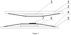
- Figure 1 shows the assembly diagram of the disclosure; 1: first plate, 2: first protective film, 3. first sliding block, 4. second protective film, 5. second plate, 6. second sliding block, 7. proton exchange membrane.
- the apparatus used in the flattening method includes the first plate 1 and the second plate 5, and the first plate 1 is placed over the second plate 5 and the lower surface of the first plate 1 is covered with the first protective film 2.
- the first sliding block 3, which has a flat the lower surface, is disposed between the first plate 1 and the first protective film 2.
- the first sliding block 3 can slide back and forth along the lower surface of the first plate 1.
- the second protective film 4 is disposed on the upper surface of the second plate 5.
- the second sliding block 6, whose the upper surface is flat is disposed between the second plate 5 and the second protective film 4.
- the second sliding block 6 can slide back and forth along the upper surface of the second plate 5.
- the first protective film 2 and the second protective film 4 are opposed to each other, and the first sliding block 3 and the second sliding block 6 are opposed to each other.
- the upper surface of the first plate 1 is the placement area where the flattened proton exchange membrane 7 is placed.
- the first plate 1 is connected to the driving force output end of first driving device.
- the first plate 1 is driven up and down or left and right by the first driving device.
- the first sliding block 3 and the second sliding block 6 are respectively connected to driving force output end of the second driving device, and are driven to move left and right by the second driving device.
- the first driving device is a motor whose output shaft is connected with the first plate 1.
- the second driving device is a motor or a cylinder, and the motor output shaft or the cylinder output rod is connected to the first sliding block 3 and the second sliding block 6.
- the said apparatus also includes a CCD identification system that can photograph and identify the proton exchange membrane 7 located below the first sliding block 3 and its relative position on the lower surface of the first plate 1, and generate a control signal which can make the first driving device move the first plate 1 to the specified placement area.
- a CCD identification system that can photograph and identify the proton exchange membrane 7 located below the first sliding block 3 and its relative position on the lower surface of the first plate 1, and generate a control signal which can make the first driving device move the first plate 1 to the specified placement area.
- the flattening method of proton exchange membrane is as follows:
- the liquid soaking proton exchange membrane is a phosphoric acid solution with a mass concentration of 70-95%.
- the pressures described in steps 2) and 4) are 50-500N.
- step 3 when the proton exchange membrane 7 is located below the first sliding block, the first plate 1, together with the first sliding block 3, the first protective film 2, and the flatten proton exchange membrane 7 are moved by a mechanical part to a placement area where pictures can be taken, identifying the position the proton exchange membrane 7 relative to the first protective film 2 by CCD.
- the placement area in step 4) is where the membrane electrode assembly is being assembled. And the position of the said flattened proton exchange membrane 7 on the assembly position of the membrane electrode directly faces the membrane electrode assembly to be assembled.
- the method to align the flattened proton exchange membrane 7 on the assembly position of the membrane electrode assembly is as follows: by controlling the mechanical part to place the proton exchange membrane 7 directly above the electrode to be assembled according to the position recognized by the CCD.
- the flattening and rapid movement of the electrolyte membrane can be realized.
- the system of the current disclosure can shorten service time from 1-2 min to 10-30 s, and compared with the traditional manual membrane electrode flattening, the precision of the membrane electrode assembly can be improved from ⁇ 0.5 mm to ⁇ 0.02 mm, which greatly improves the processing efficiency of proton exchange membrane and provides a method for automatic and intelligent preparation of membrane electrode assembly.
Landscapes
- Engineering & Computer Science (AREA)
- Manufacturing & Machinery (AREA)
- Life Sciences & Earth Sciences (AREA)
- Sustainable Development (AREA)
- Sustainable Energy (AREA)
- Chemical & Material Sciences (AREA)
- Chemical Kinetics & Catalysis (AREA)
- Electrochemistry (AREA)
- General Chemical & Material Sciences (AREA)
- Fuel Cell (AREA)
Abstract
Description
- The disclosure relates to the technical field of fuel cell and, more specifically, provides a method and apparatus for flattening a proton exchange membrane of a fuel cell.
- A fuel cell is an energy conversion device that converts the chemical energy stored in H2 and O2 directly into electrical energy. The transformation process is not restricted by Carnot cycle process, so that it has high energy conversion efficiency. In addition, fuel cell also has the characteristics of noiseless, vibration-free, clean emission, environmentally friendly and modularized layout, which provide fuel cell technology a broad application prospect in the fields of new energy vehicles and distributed power stations. The proton exchange membrane of the membrane electrode assembly (MEA) is one of the core regions of electrochemical reaction, which is mainly composed of polymer. As the main medium of proton transfer in the fuel cell, the electrolyte in the proton exchange membrane directly affects its performance and life. For the proton exchange membrane obtained by post-impregnation method, its physical form is relatively soft and difficult to flatten. Meanwhile, a great deal of electrolyte solution remains on the surface so that a part of the surface electrolyte solution has to be removed to obtain an electrolyte solution compatible with the gas diffusion layer in the membrane electrode assembly .
- At present, the treatment methods are mainly manual flattening and a porous material to adsorb electrolyte from the surface. There are some problems such as uneven leveling, uneven distribution of electrolyte solution and low production efficiency. Uneven distribution of electrolyte solution leads to uneven distribution of electrode current density, which affects consistency and life of the membrane electrode assembly. Low production efficiency directly affects the industrialization process of fuel cells. No similar research has been carried out on the efficient control methods and apparatus.
- Based on the above, the disclosure presents a method and apparatus for flattening a proton exchange membrane of a fuel cell membrane electrode units. This method can realize the efficient and rapid processing of fuel cell membrane electrode proton exchange membrane and improve the uniform consistency of electrolyte solution, which will be of great significance to promote the industrialization process of fuel cell.
- The disclosure provides methods and apparatus for flattening a proton exchange membrane for a fuel cell membrane electrode assembly. By the liquid surface tension on the surface of the proton exchange membrane, one end of the proton exchange membrane is preferably separated from the substrate surface through the relative movement between the two tension surfaces so as to transfer the proton exchange membrane to the another surface after the movement. When the two tension surfaces move relatively to each other, the electrolyte solution on the surface of the proton exchange membrane is evenly distributed on the surface through the applied pressure and friction, so as to achieve the goal of flattening and even distribution of the electrolyte.
- To achieve above objectives, the disclosure adopts the following technical scheme: an apparatus includes the first plate and the second plate, and the first plate is placed over the second plate and the lower surface of the first plate is covered with the first protective film. The first sliding block, which has a flat the lower surface, is disposed between the first plate and the first protective film. The first sliding block can slide back and forth along the lower surface of the first plate. The second protective film is disposed on the upper surface of the second plate. Likewise, the second sliding block, whose the upper surface is flat, is disposed between the second plate and the second protective film. The second sliding block can slide back and forth along the upper surface of the second plate. The first protective film and the second protective film are opposed to each other, and the first sliding block and the second sliding block are opposed to each other.
- The flattening method of proton exchange membrane is as follows:
- 1) The proton exchange membrane to be flattened is soaked with liquid on its upper and lower surfaces, and is placed on the second protective film, so that the proton exchange membrane is located above the second sliding block.
- 2) Move the first plate downward[[,]] so that the first protective film is in contact with the proton exchange membrane to be flattened, and the proton exchange membrane to be flattened is located beneath the first sliding block. Apply a pressure between the first sliding block and the second sliding block.
- 3) Slide the second sliding block to the left or right to separate it from the proton exchange membrane. The proton exchange membrane is transferred to the lower surface of the first protective film and underneath the first sliding block.
- 4) Move the first plate to the placement area of proton exchange membrane after flattening that has a flat surface. Apply a pressure between the first sliding block and the upper surface of the placement area.
- 5) Slide the first sliding block to the left or right so that the first sliding block is separated from the top of the proton exchange membrane. After flattening, the proton exchange membrane is transferred to the upper surface of the placement area.
- The liquid soaking the proton exchange membrane is a phosphoric acid solution with a mass concentration of 70-95%.
- The pressures described in steps 2) and 4) are 50-500N.
- In step 3), when the proton exchange membrane to be flattened is located below the first sliding block, the first plate, together with the first sliding block, the first protective film, and the proton exchange membrane are moved by a mechanical part to a placement area where pictures can be taken, identifying the position the proton exchange membrane relative to the first protective film by CCD.
- The placement area in step 4) is where the membrane electrode assembly is being assembled. And the position of the said flattened proton exchange membrane on the assembly position of the membrane electrode directly face the membrane electrode assembly to be assembled.
- The method to align the flattened proton exchange membrane on the assembly position of the membrane electrode assembly is as follows: by controlling the mechanical part to place the proton exchange membrane directly above the electrode to be assembled according to the position recognized by the CCD.
- The apparatus used for flattening the proton exchange membrane includes the first plate and the second plate, and the first plate is disposed above the second plate. The lower surface of the first plate is the first protective film. The first sliding block, whose the lower surface is flat, is disposed between the first plate and the first protective film. The first sliding block can slide back and forth along the lower surface of the first plate. The second protective film is on the upper surface of the second plate. Likewise, the second sliding block, whose the upper surface is flat, is disposed between the second plate and the second protective film. The second sliding block can slide back and forth along the upper surface of the second plate. The first protective film and the second protective film are opposed to each other, and the first sliding block and the second sliding block are opposed to each other. The upper surface of the first plate is the placement area where the flattened proton exchange membrane is placed.
- The first plate is connected to the driving force output end of the first driving device. The first plate is driven up and down or left and right by the first driving device. The first sliding block and the second sliding block are respectively connected to driving force outputs of the second driving device, and are driven to move left and right by the second driving device.
- The first driving device is a motor whose output shaft is connected with the first plate.
- The second driving device is a motor or a cylinder, and the motor output shaft or the cylinder output rod is connected to the first sliding block and the second sliding block.
- The apparatus also includes a CCD identification system that can photograph and identify the proton exchange membrane located below the first sliding block and its relative position on the lower surface of the first plate, and generate a control signal which can make the first driving device move the first plate to the specified placement area. By controlling the moving position of the first plate, the electrode to and the proton exchange membrane are to be assembled at the specified location.
- Thus, the flattening and rapid movement of the electrolyte membrane can be realized. Compared with the traditional manual flattening method, the system of the current disclosure can shorten the service time from 1-2min to 10-30s, and compared with the membrane electrode assembly using the traditional manual flattening, the precision of the membrane electrode assembly can be improved from ±0.5mm to ± 0.02mm, which greatly improves the processing efficiency of proton exchange membrane and provides a method for automatic and intelligent preparation of membrane electrode units.
-
Figure 1 shows the assembly diagram of the disclosure;
1: first plate, 2: first protective film, 3. first sliding block, 4. second protective film, 5. second plate, 6. second sliding block, 7. proton exchange membrane. - The apparatus used in the flattening method includes the
first plate 1 and thesecond plate 5, and thefirst plate 1 is placed over thesecond plate 5 and the lower surface of thefirst plate 1 is covered with the first protective film 2. The first slidingblock 3, which has a flat the lower surface, is disposed between thefirst plate 1 and the first protective film 2. The first slidingblock 3 can slide back and forth along the lower surface of thefirst plate 1. The secondprotective film 4 is disposed on the upper surface of thesecond plate 5. Likewise, the second slidingblock 6, whose the upper surface is flat, is disposed between thesecond plate 5 and the secondprotective film 4. The second slidingblock 6 can slide back and forth along the upper surface of thesecond plate 5. The first protective film 2 and the secondprotective film 4 are opposed to each other, and the first slidingblock 3 and the second slidingblock 6 are opposed to each other. The upper surface of thefirst plate 1 is the placement area where the flattenedproton exchange membrane 7 is placed. - The
first plate 1 is connected to the driving force output end of first driving device. Thefirst plate 1 is driven up and down or left and right by the first driving device. The first slidingblock 3 and the second slidingblock 6 are respectively connected to driving force output end of the second driving device, and are driven to move left and right by the second driving device. - The first driving device is a motor whose output shaft is connected with the
first plate 1. - The second driving device is a motor or a cylinder, and the motor output shaft or the cylinder output rod is connected to the first sliding
block 3 and the second slidingblock 6. - The said apparatus also includes a CCD identification system that can photograph and identify the
proton exchange membrane 7 located below the first slidingblock 3 and its relative position on the lower surface of thefirst plate 1, and generate a control signal which can make the first driving device move thefirst plate 1 to the specified placement area. By controlling the moving position of thefirst plate 1, the positioning assembling of the electrode to be assembled and the proton exchange membrane to be assembled can be realized at the specified location. - The flattening method of proton exchange membrane is as follows:
- 1) The proton exchange membrane to be flattened 7 is soaked with liquid on the upper and lower surfaces, and is placed on the second
protective film 4 so that theproton exchange membrane 7 is located above the second slidingblock 6. - 2) Move the
first plate 1 downward so that the first protective film 2 is in contact with the proton exchange membrane to be flattened 7, and theproton exchange membrane 7 which is to be flattened is located beneath the first slidingblock 3. Apply a pressure between the first slidingblock 3 and the second slidingblock 6. - 3) Slide the second sliding
block 6 to the left or right to separate it from theproton exchange membrane 7. Theproton exchange membrane 7 is transferred to the lower surface of the first protective film 2, and underneath the first slidingblock 3. - 4) Move the
first plate 1 to the placement area ofproton exchange membrane 7 after flattening that has a flat surface. Apply a pressure between the first slidingblock 3 and the upper surface of the placement area. - 5) Slide the first sliding
block 3 to the left or right so that the first slidingblock 3 is separated from the top of theproton exchange membrane 7. After flattening, the proton exchange membrane is transferred to the upper surface of the placement area. - The liquid soaking proton exchange membrane is a phosphoric acid solution with a mass concentration of 70-95%.
- The pressures described in steps 2) and 4) are 50-500N.
- In step 3), when the
proton exchange membrane 7 is located below the first sliding block, thefirst plate 1, together with the first slidingblock 3, the first protective film 2, and the flattenproton exchange membrane 7 are moved by a mechanical part to a placement area where pictures can be taken, identifying the position theproton exchange membrane 7 relative to the first protective film 2 by CCD. - The placement area in step 4) is where the membrane electrode assembly is being assembled. And the position of the said flattened
proton exchange membrane 7 on the assembly position of the membrane electrode directly faces the membrane electrode assembly to be assembled. - The method to align the flattened
proton exchange membrane 7 on the assembly position of the membrane electrode assembly is as follows: by controlling the mechanical part to place theproton exchange membrane 7 directly above the electrode to be assembled according to the position recognized by the CCD. - As such, the flattening and rapid movement of the electrolyte membrane can be realized. Compared with the traditional manual flattening method, the system of the current disclosure can shorten service time from 1-2 min to 10-30 s, and compared with the traditional manual membrane electrode flattening, the precision of the membrane electrode assembly can be improved from ±0.5 mm to ±0.02 mm, which greatly improves the processing efficiency of proton exchange membrane and provides a method for automatic and intelligent preparation of membrane electrode assembly.
Claims (9)
- A process to flatten the proton exchange membrane for the fuel cell, characterized by:said apparatus comprises a first plate (1) and the second plate (5), and the first plate (1) is placed over the second plate (5) and the lower surface of the first plate (1) is covered with the first protective film (2), the first sliding block (3), which has a flat the lower surface, is disposed between the first plate (1) and the first protective film (2), the first sliding block (3) can slide back and forth along the lower surface of the first plate (1), the second protective film (4) is disposed on the upper surface of the second plate (5), likewise, the second sliding block (6), whose the upper surface is flat, is disposed between the second plate (5) and the second protective film (4), the second sliding block (6) can slide back and forth along the upper surface of the second plate (5), the first protective film (2) and the second protective film (4) are opposed to each other, and the first sliding block (3) and the second sliding block (6) are opposed to each other;The flattening method of proton exchange membrane comprises:1) The proton exchange membrane to be flattened (7) is soaked with liquid on the upper and lower surfaces, and is placed on the second protective film (4) so that the proton exchange membrane (7) is located above the second sliding block (6);2) Move the first plate (1) downward so that the first protective film (2) is in contact with the proton exchange membrane to be flattened (7), and the proton exchange membrane (7) which is to be flattened is located beneath the first sliding block (3); apply a pressure between the first sliding block (3) and the second sliding block (6);3) Slide the second sliding block (6) to the left or right to separate it from the proton exchange membrane (7), the proton exchange membrane (7) is transferred to the lower surface of the first protective film (2), and underneath the first sliding block (3);4) Move the first plate (1) to the placement area of proton exchange membrane (7) after flattening that has a flat surface, apply a pressure between the first sliding block (3) and the upper surface of the placement area;5) Slide the first sliding block (3) to the left or right so that the first sliding block (3) is separated from the top of the proton exchange membrane (7), after flattening, the proton exchange membrane is transferred to the upper surface of the placement area.
- The flattening method according to claim 1, characterized by: the liquid soaking the proton exchange membrane is a phosphoric acid solution with a mass concentration of 70-95%.
- The flattening method according to claim 1, characterized by:
the pressures described in steps 2) and 4) are 50-500N. - The flattening method according to claim 1, characterized by:in step 3), when the proton exchange membrane (7) is located below the first sliding block, the first plate 1, together with the first sliding block (3), the first protective film (2), and the flatten proton exchange membrane (7) are moved by a mechanical part to a placement area where pictures can be taken, identifying the position the proton exchange membrane (7) relative to the first protective film (2) by CCD,and, in step 4), the placement area is where the membrane electrode assembly is being assembled, and the position of the said flattened proton exchange membrane 7 on the assembly position of the membrane electrode directly faces the membrane electrode assembly to be assembled.
- The flattening method according to claim 4, characterized by:aligning the flattened proton exchange membrane (7) on the assembly position of the membrane electrode assembly by controlling the mechanical part to place the proton exchange membrane (7) directly above the electrode to be assembled according to the position recognized by the CCD.
- A apparatus used in the said flattening method according to claim 1, characterized by:said apparatus comprises the first plate (1) and the second plate (5), and the first plate (1) is placed over the second plate (5) and the lower surface of the first plate (1) is covered with the first protective film (2), the first sliding block (3), which has a flat the lower surface, is disposed between the first plate (1) and the first protective film (2), the first sliding block (3) can slide back and forth along the lower surface of the first plate (1), the second protective film (4) is disposed on the upper surface of the second plate (5), likewise, the second sliding block (6), whose the upper surface is flat, is disposed between the second plate (5) and the second protective film (4), the second sliding block (6) can slide back and forth along the upper surface of the second plate (5), the first protective film (2) and the second protective film (4) are opposed to each other, and the first sliding block (3) and the second sliding block (6) are opposed to each other, the upper surface of the first plate (1) is the placement area where the flattened proton exchange membrane (7) is placed,the first plate (1) is connected to the driving force output end of first driving device, the first plate (1) is driven up and down or left and right by the first driving device, the first sliding block (3) and the second sliding block (6) are respectively connected to driving force output end of the second driving device, and are driven to move left and right by the second driving device.
- The apparatus according to claim 6, characterized by:
the first driving device is a motor whose output shaft is connected with the first plate(1). - The apparatus according to claim 6, characterized by:
the second driving device is a motor or a cylinder, and the motor output shaft or the cylinder output rod is connected to the first sliding block(3) and the second sliding block(6). - The apparatus according to claim 6, characterized by:
the apparatus further comprises a CCD identification system that can photograph and identify the proton exchange membrane 7 located below the first sliding block 3 and its relative position on the lower surface of the first plate 1, and generate a control signal which can make the first driving device move the first plate 1 to the specified placement area, and by controlling the moving position of the first plate, the electrode and the proton exchange membrane are to be assembled at the specified location.
Applications Claiming Priority (2)
| Application Number | Priority Date | Filing Date | Title |
|---|---|---|---|
| CN201911267441.7A CN112952168B (en) | 2019-12-11 | 2019-12-11 | Flattening method and device for fuel cell proton exchange membrane |
| PCT/CN2019/125122 WO2021114225A1 (en) | 2019-12-11 | 2019-12-13 | Method and device for flattening fuel cell proton exchange membrane |
Publications (2)
| Publication Number | Publication Date |
|---|---|
| EP4075586A1 true EP4075586A1 (en) | 2022-10-19 |
| EP4075586A4 EP4075586A4 (en) | 2024-12-11 |
Family
ID=76233997
Family Applications (1)
| Application Number | Title | Priority Date | Filing Date |
|---|---|---|---|
| EP19929197.2A Pending EP4075586A4 (en) | 2019-12-11 | 2019-12-13 | METHOD AND DEVICE FOR FLATTENING A PROTON EXCHANGE MEMBRANE OF A FUEL CELL |
Country Status (4)
| Country | Link |
|---|---|
| US (1) | US12155096B2 (en) |
| EP (1) | EP4075586A4 (en) |
| CN (1) | CN112952168B (en) |
| WO (1) | WO2021114225A1 (en) |
Families Citing this family (2)
| Publication number | Priority date | Publication date | Assignee | Title |
|---|---|---|---|---|
| CN114361546B (en) * | 2022-03-18 | 2022-06-07 | 河南师范大学 | Ultrasonic type micropore structure fuel cell proton exchange membrane processing equipment |
| CN117538359B (en) * | 2023-11-24 | 2024-08-06 | 深圳市通用氢能科技有限公司 | Quick evaluation method for mechanical life of proton membrane |
Family Cites Families (12)
| Publication number | Priority date | Publication date | Assignee | Title |
|---|---|---|---|---|
| EP1229602B1 (en) * | 2000-07-06 | 2010-11-24 | Panasonic Corporation | Method for producing film electrode jointed product and method for producing solid polymer type fuel cell |
| DE102004034139A1 (en) * | 2004-07-15 | 2006-02-02 | Pemeas Gmbh | Process for the preparation of membrane-electrode assemblies |
| CN101241994B (en) * | 2004-09-14 | 2011-01-26 | 南亚电路板股份有限公司 | Method for Improving Contact Between Bipolar Plate and Proton Exchange Membrane of Flat Fuel Cell |
| US20070111072A1 (en) * | 2005-11-14 | 2007-05-17 | Ryan Wayne | Indicator fixed ion-exchange membrane |
| US20070275848A1 (en) * | 2006-05-23 | 2007-11-29 | Hsi-Ming Shu | Manufacturing process and structure of membrane electrode assembly layer for fuel cell |
| CN101887975B (en) * | 2010-04-09 | 2012-07-18 | 新源动力股份有限公司 | A kind of integrated preparation method of membrane-membrane electrode for fuel cell |
| CN204464351U (en) * | 2015-01-08 | 2015-07-08 | 昆山桑莱特新能源科技有限公司 | A kind of production and processing device of fuel battery proton exchange film |
| KR101684550B1 (en) * | 2015-07-29 | 2016-12-08 | 현대자동차 주식회사 | Device and method for manufacturing membrane-electrode assembly of fuel cell |
| CN205069728U (en) * | 2015-09-28 | 2016-03-02 | 戴瑞米克襄阳电池隔膜有限公司 | Battery separator removes fold device |
| CN205264813U (en) * | 2015-12-22 | 2016-05-25 | 惠州Tcl金能电池有限公司 | Packaging film pollution discharge amount |
| FR3060862A1 (en) * | 2016-12-20 | 2018-06-22 | Compagnie Generale Des Etablissements Michelin | PROCESS FOR MANUFACTURING MEMBRANE-ELECTRODE ASSEMBLY FOR FUEL CELL |
| CN109049649A (en) * | 2018-07-04 | 2018-12-21 | 合肥国轩高科动力能源有限公司 | A PET film thermoforming device |
-
2019
- 2019-12-11 CN CN201911267441.7A patent/CN112952168B/en active Active
- 2019-12-13 WO PCT/CN2019/125122 patent/WO2021114225A1/en not_active Ceased
- 2019-12-13 EP EP19929197.2A patent/EP4075586A4/en active Pending
- 2019-12-13 US US15/733,880 patent/US12155096B2/en active Active
Also Published As
| Publication number | Publication date |
|---|---|
| US12155096B2 (en) | 2024-11-26 |
| CN112952168A (en) | 2021-06-11 |
| WO2021114225A1 (en) | 2021-06-17 |
| EP4075586A4 (en) | 2024-12-11 |
| US20210367244A1 (en) | 2021-11-25 |
| CN112952168B (en) | 2023-04-18 |
Similar Documents
| Publication | Publication Date | Title |
|---|---|---|
| CN111063925B (en) | Catalyst coated membrane, fuel cell and method of making | |
| CN114024000B (en) | Anode activation method of proton exchange membrane fuel cell stack | |
| US12155096B2 (en) | Method for flattening proton exchange membrane for fuel cell and apparatus therefor | |
| CN101752570B (en) | Preparation method of proton exchange membrane fuel cell electrode | |
| CN1405915A (en) | Modular battery cell and modular battery unit of proton exchange membrane fuel cell | |
| CN110911714A (en) | Proton exchange membrane fuel cell stack activation method | |
| CN100356625C (en) | Apparatus and method for releasing fuel cell components from a press fit fixture | |
| CN109921055B (en) | A kind of ultra-thin graphene composite flexible graphite bipolar plate and preparation method thereof | |
| US11335913B2 (en) | Method for manufacturing solid oxide cell having three-dimensional ceramic composite interface structure | |
| CN109346752B (en) | A kind of preparation method of electrolyte-supported solid oxide fuel cell zirconium-based electrolyte membrane | |
| CN215644576U (en) | A pressing device for maintaining pressure of membrane electrodes of hydrogen fuel cells | |
| CN115000479B (en) | Modified proton exchange membrane and preparation method and application thereof | |
| CN1992401A (en) | Method of selecting non-humidification operating condition for proton exchange membrane fuel cell | |
| CN101867052A (en) | A spoke-type self-breathing micro fuel cell and its preparation method | |
| CN120511323A (en) | Method for activating solid polymer fuel cell | |
| CN215180730U (en) | A high temperature polymer electrolyte membrane fuel cell membrane electrode forming detection device | |
| CN1933229A (en) | Method for producing anode-supporting solid oxide fuel cell | |
| CN112054224B (en) | High-strength ultrathin integrated proton exchange membrane | |
| CN105428670A (en) | Special polar plate for high-power-density PEMFC (proton exchange membrane fuel cell) pile and preparation method of polar plate | |
| CN219246723U (en) | Membrane electrode dispensing and attaching platform | |
| CN119708333B (en) | An Electrolyte Photosensitive Slurry and Its Preparation and Application | |
| CN224096696U (en) | Fabrication fixture for fuel cell single cells | |
| CA2579761C (en) | Production method for fuel cell using molten electrolyte formed into thin-film electrolyte | |
| CN119864497B (en) | A continuously produced flexible composite solid electrolyte film and its preparation method | |
| CN211350829U (en) | Fuel cell pole piece rolling mechanism |
Legal Events
| Date | Code | Title | Description |
|---|---|---|---|
| STAA | Information on the status of an ep patent application or granted ep patent |
Free format text: STATUS: UNKNOWN |
|
| STAA | Information on the status of an ep patent application or granted ep patent |
Free format text: STATUS: THE INTERNATIONAL PUBLICATION HAS BEEN MADE |
|
| PUAI | Public reference made under article 153(3) epc to a published international application that has entered the european phase |
Free format text: ORIGINAL CODE: 0009012 |
|
| STAA | Information on the status of an ep patent application or granted ep patent |
Free format text: STATUS: REQUEST FOR EXAMINATION WAS MADE |
|
| 17P | Request for examination filed |
Effective date: 20201127 |
|
| AK | Designated contracting states |
Kind code of ref document: A1 Designated state(s): AL AT BE BG CH CY CZ DE DK EE ES FI FR GB GR HR HU IE IS IT LI LT LU LV MC MK MT NL NO PL PT RO RS SE SI SK SM TR |
|
| DAV | Request for validation of the european patent (deleted) | ||
| DAX | Request for extension of the european patent (deleted) | ||
| A4 | Supplementary search report drawn up and despatched |
Effective date: 20241113 |
|
| RIC1 | Information provided on ipc code assigned before grant |
Ipc: H01M 50/40 20210101AFI20241107BHEP |