EP4075581A1 - Battery module and battery pack comprising same - Google Patents
Battery module and battery pack comprising same Download PDFInfo
- Publication number
- EP4075581A1 EP4075581A1 EP21795900.6A EP21795900A EP4075581A1 EP 4075581 A1 EP4075581 A1 EP 4075581A1 EP 21795900 A EP21795900 A EP 21795900A EP 4075581 A1 EP4075581 A1 EP 4075581A1
- Authority
- EP
- European Patent Office
- Prior art keywords
- battery
- cell stack
- frame
- module
- battery cell
- Prior art date
- Legal status (The legal status is an assumption and is not a legal conclusion. Google has not performed a legal analysis and makes no representation as to the accuracy of the status listed.)
- Granted
Links
Images


Classifications
-
- H—ELECTRICITY
- H01—ELECTRIC ELEMENTS
- H01M—PROCESSES OR MEANS, e.g. BATTERIES, FOR THE DIRECT CONVERSION OF CHEMICAL ENERGY INTO ELECTRICAL ENERGY
- H01M50/00—Constructional details or processes of manufacture of the non-active parts of electrochemical cells other than fuel cells, e.g. hybrid cells
- H01M50/20—Mountings; Secondary casings or frames; Racks, modules or packs; Suspension devices; Shock absorbers; Transport or carrying devices; Holders
- H01M50/204—Racks, modules or packs for multiple batteries or multiple cells
- H01M50/207—Racks, modules or packs for multiple batteries or multiple cells characterised by their shape
- H01M50/211—Racks, modules or packs for multiple batteries or multiple cells characterised by their shape adapted for pouch cells
-
- H—ELECTRICITY
- H01—ELECTRIC ELEMENTS
- H01M—PROCESSES OR MEANS, e.g. BATTERIES, FOR THE DIRECT CONVERSION OF CHEMICAL ENERGY INTO ELECTRICAL ENERGY
- H01M50/00—Constructional details or processes of manufacture of the non-active parts of electrochemical cells other than fuel cells, e.g. hybrid cells
- H01M50/20—Mountings; Secondary casings or frames; Racks, modules or packs; Suspension devices; Shock absorbers; Transport or carrying devices; Holders
- H01M50/202—Casings or frames around the primary casing of a single cell or a single battery
-
- H—ELECTRICITY
- H01—ELECTRIC ELEMENTS
- H01M—PROCESSES OR MEANS, e.g. BATTERIES, FOR THE DIRECT CONVERSION OF CHEMICAL ENERGY INTO ELECTRICAL ENERGY
- H01M50/00—Constructional details or processes of manufacture of the non-active parts of electrochemical cells other than fuel cells, e.g. hybrid cells
- H01M50/50—Current conducting connections for cells or batteries
- H01M50/502—Interconnectors for connecting terminals of adjacent batteries; Interconnectors for connecting cells outside a battery casing
- H01M50/505—Interconnectors for connecting terminals of adjacent batteries; Interconnectors for connecting cells outside a battery casing comprising a single busbar
-
- H—ELECTRICITY
- H01—ELECTRIC ELEMENTS
- H01M—PROCESSES OR MEANS, e.g. BATTERIES, FOR THE DIRECT CONVERSION OF CHEMICAL ENERGY INTO ELECTRICAL ENERGY
- H01M2220/00—Batteries for particular applications
- H01M2220/20—Batteries in motive systems, e.g. vehicle, ship, plane
-
- Y—GENERAL TAGGING OF NEW TECHNOLOGICAL DEVELOPMENTS; GENERAL TAGGING OF CROSS-SECTIONAL TECHNOLOGIES SPANNING OVER SEVERAL SECTIONS OF THE IPC; TECHNICAL SUBJECTS COVERED BY FORMER USPC CROSS-REFERENCE ART COLLECTIONS [XRACs] AND DIGESTS
- Y02—TECHNOLOGIES OR APPLICATIONS FOR MITIGATION OR ADAPTATION AGAINST CLIMATE CHANGE
- Y02E—REDUCTION OF GREENHOUSE GAS [GHG] EMISSIONS, RELATED TO ENERGY GENERATION, TRANSMISSION OR DISTRIBUTION
- Y02E60/00—Enabling technologies; Technologies with a potential or indirect contribution to GHG emissions mitigation
- Y02E60/10—Energy storage using batteries
Definitions
- the present invention relates to a battery module and a battery pack including the same, and more specifically, to a battery module with improved assembly ability and a battery pack including the same.
- Secondary batteries having high application characteristics and electrical characteristics such as high energy density according to their products are widely applied to battery vehicles, hybrid vehicles, and electric power storage devices driven by electric driving sources as well as portable devices. These secondary batteries are attracting attention as new energy sources for improving environmental-friendliness and energy efficiency in that they do not generate any by-products of energy use as well as their primary merit, in which they can drastically reduce the use of fossil fuels.
- the battery module may include a frame member that receives the battery cell stack in an internal space with front and rear openings.
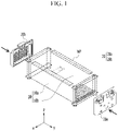
- FIG. 1 is a perspective view showing a battery module according to a conventional module frame.
- FIG. 2 is a view showing a cross-section taken along an xz plane FIG. 1 .
- a battery module may include a module frame 10 of which a front surface and a rear surface are opened to cover a battery cell stack 12 formed by stacking a plurality of battery cells 11 and an end plate 20 covering the front surface and the rear surface of the module frame 10.
- the module frame 10 may include a U-shaped frame 10a and an upper plate 10b covering the opened portion of the U-shaped frame 10a.
- the U-shaped frame 10a may include a bottom part 10a1 covering the lower surface of the battery cell stack 12 and two side parts 10a2 having a structure protruded upward from both sides of the bottom part 10a1.
- the end plate 20 may include a front plate 20a covering one side of the module frame 10 and a rear plate 20b covering the other side of the module frame 10.
- the problem to be solved by the present invention is to provide a battery module with improved assembly ability and a battery pack including the same.
- a battery module includes a battery cell stack in which a plurality of battery cells are stacked; a module frame surrounding the battery cell stack; a busbar frame covering the front/rear surfaces of the battery cell stack exposed from the module frame; and an end plate covering the busbar frame, wherein the module frame includes a lower frame covering the lower part and both sides of the battery cell stack, and an upper plate covering the upper part of the battery cell stack, and at least one assemble guide part is formed at the corner of the lower frame that joins the upper plate.
- the lower frame may include a bottom part supporting the lower part of the battery cell stack and two side parts extending upward from both ends of the bottom part, and the assemble guide part may be formed at the corner of the upper end of the side part.
- the assemble guide part may include a supporting part of a protrusion shape protruded in one direction and a depressed part formed on both sides of the supporting part.
- the depressed part may have an escape shape in which the upper end corner of the side part of the lower frame is concave in the direction toward the bottom part of the lower frame.
- a groove part to which the supporting part of the assemble guide part may be assembled is formed on the upper plate.
- the groove part may have a structure in which both corresponding corners of the upper plate are recessed in a direction facing each other.
- An escape part may be formed on both ends of the groove part.
- a battery pack according to another embodiment of the present invention includes the battery module described above.
- a protrude-type assemble guide structure in the module frame, it is possible to prevent a misalignment from occurring when assembling the module frame. Through this assembly improvement, it is possible to prevent welding defects from occurring during a module frame welding.
- the phrase “in a plan view” means when an object portion is viewed from above, and the phrase “in a cross-section” means when a cross-section taken by vertically cutting an object portion is viewed from the side.
- FIG. 3 is an exploded perspective view showing a battery module according to an embodiment of the present invention.
- a battery module includes a battery cell stack 100 in which a plurality of battery cells 110 are stacked, a module frame 200 receiving the battery cell stack 100, a busbar frame 400 formed on the front/rear surfaces of the battery cell stack 100, and an end plate 600 covering the outside of the busbar frame 400 based on the d battery cell stack 100.
- the battery cell 110 is a secondary battery and may be configured as a pouch-type secondary battery.
- the battery cells 110 may be configured in plurality, and a plurality of battery cells 110 may be stacked to each other to be electrically connected to each other to form a battery cell stack 100.
- a plurality of battery cells 110 may include an electrode assembly, a cell case, and an electrode lead protruded from the electrode assembly, respectively.
- the busbar frame 400 may be equipped with a busbar 411 and a connector 500.
- the connector 500 may sense a voltage and temperature from the busbars mounted on the busbar frame 400 or a thermistor and transmit it to a BMS (Battery Management System).
- BMS Battery Management System
- a first connector 510 may be formed on the busbar frame 400 positioned in front of the battery cell stack 100
- a second connector 520 may be formed on the busbar frame 400 positioned at the rear surface of the battery cell stack 100.
- a connector was formed on only one busbar frame part of two busbar frames formed on the front/rear surfaces of the battery cell stack 100, and the busbar frame part on which a connector is not formed transmitted the voltage and temperature sensing information to the connector located on the opposite side of the reference of the battery cell stack through a flexible flat cable.
- the process of assembling the flexible flat cable and the process of checking whether there is any problem in the connection through the flexible flat cable were separately required by positioning the flexible flat cable on the upper side of the battery cell stack.
- the first and second connectors 510 and 520 are separately formed on one side of each busbar frame 400 formed on the front/rear surfaces of the battery cell stack 100, so that the sensed voltage and temperature may be transmitted to the BMS in both directions through the connectors formed on each busbar frame 400 without any need of the separate assemble of the flexible flat cable.
- a manufacturing cost of the battery module may be reduced and the battery module structure may be simplified.
- the assemble process of the flexible flat cable and the process of checking the connection defects are eliminated, thereby simplifying the battery module manufacturing process.
- the battery cell stack 100 is disposed in the module frame 200.
- the module frame 200 may include a lower frame 210 covering the lower surface and both sides of the battery cell stack 100, and an upper plate 220 covering the upper surface of the battery cell stack 100.
- the battery cell stack 100 may be disposed to the lower frame 210. Thereafter, the upper plate 220 may be assembled to cover the upper part of the battery cell stack 100. At this time, by fixing the upper plate 220 and the lower frame 210, the battery cell stack 100 may be stably disposed within the module frame 200.
- the lower frame 210 of the module frame 200 that accommodates the battery cell stack 100 may be a U-shaped frame.
- the U-shaped frame 210 may include a bottom part 210a and two side parts 210b extending upward from both ends of the bottom part 210a.
- the bottom part 210a may cover the lower surface (a direction opposite the z-axis) of the battery cell stack 100
- the side parts 210b may cover both sides (a direction of the x-axis and a direction opposite to the x-axis direction) of the battery cell stack 100.
- the upper plate 220 may be formed as a single plate-shaped structure surrounding the upper surface (the z-axis direction) except for the lower surface and the both sides covered by the U-shaped frame 210.
- the upper plate 220 and the U-shaped frame 210 may form a structure that covers the battery cell stack 100 up, down, left, and right by being joined by welding or the like while the corresponding corners are in contact with each other.
- the battery cell stack 100 may be physically protected through the upper plate 220 and the U-shaped frame 210.
- the upper plate 220 and the U-shaped frame 210 may include a metal material having predetermined strength.
- welding may be performed to join the U-shaped frame 210 and the upper plate 220 of the module frame 200.
- it is necessary to fix the U-shaped frame 210 and the upper plate 220 so that the joint surfaces of the side part 210b of the U-shaped frame 210 and the upper plate 220 are positioned corresponding to each other.
- laser welding may be performed for the welding, and damage to internal parts including the battery cells may be caused by the laser itself or welding spatters penetrated during the welding process.
- the weld line is also misaligned, and in this case, a larger amount of welding spatter is inflowed into the battery module where the battery cells are located, thereby causing problems.
- the battery module according to the present embodiment includes a lower frame having an assemble guide structure of a protruding type, thereby improving the assembly ability of the lower frame and upper plate, thereby preventing the welding defects. This will be described in detail with reference to FIG. 4 and FIG. 5 .
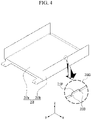
- FIG. 4 is a perspective view showing a lower frame included in a battery module of FIG. 3 .
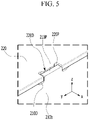
- FIG. 5 is a partial perspective view showing an assembly part of an upper plate and a lower frame in a battery module according to an embodiment of the present invention.
- the upper corner of the side part 210b of the U-shaped frame 210 may form an assemble guide part 210G.
- the assemble guide part 210G may be formed as at least one on the upper corner of the side part 210b of the U-shaped frame 210.
- a plurality of assemble guide parts 210G may be formed to be spaced apart from each other while having a predetermined interval therebetween.
- the assemble guide part 210G may include a supporting part 210P of a protrusion shape protruded in the z-axis direction and a depressed part 210D formed on both sides of the supporting part 210P.
- the depressed part 210D may have an escape shape in which the upper corner of the side part 210b of the U-shaped frame 210 is concave in the opposite direction of the z-axis.
- a groove part 220D corresponding to the assemble guide part 210G formed on the U-shaped frame 210 may be formed on the upper plate 220 according to the present embodiment.
- the groove part 220D may have a structure in which both corners of the upper plate 220 are depressed in a direction facing each other so that the assemble guide part 210G of the U-shaped frame 210 may be assembled with the upper plate 220.
- an escape part 220P may be formed on both ends of the groove part 220D. The escape part 220P minimizes a gap of the groove part 220D so that the supporting part 210P of the assemble guide part 210G may be accurately coupled to the groove part 220D.
- the assembly ability may be improved, but also the durability of the battery module may be improved.
- the horizontal direction length of the battery module becomes longer.
- the horizontal direction length may mean a length in the direction in which the battery cells are stacked.
- the coupling structure of the U-shaped frame 210 and the upper plate 220 may be distorted depending on the battery module usage condition, but according to the present embodiment, through the strong position fixation in both the x-axis direction and the y-axis direction, the coupling retention between the U-shaped frame 210 and the upper plate 220 may be improved.
- the battery module according to the present embodiment may further include an end plate 600 covering the front/rear surfaces of the battery cell stack 100.
- the end plate 600 may be positioned on the front (the opposite direction of the y-axis) and rear (the y-axis direction) of the battery cell stack 100. This end plate 600 is formed to cover the battery cell stack 100, and it is possible to physically protect the battery cell stack 100 and other electronic devices from external impact.
- a busbar frame 400 to which the busbar 411 is mounted and an insulating cover for an electrical insulation, etc. may be positioned between the battery cell stack 100 and the end plate 600.
- one or more battery modules according to an embodiment of the present invention may be packaged in a pack case to form a battery pack.
- the battery pack may be formed by mounting at least one battery module together with various control and protection systems such as a battery management system (BMS) and a cooling system.
- BMS battery management system
- the battery module described above and the battery pack including the same may be applied to various devices.
- the device may be applied to a vehicle such as an electric bicycle, an electric vehicle, and a hybrid vehicle, but is not limited thereto, and may be applied to various devices that may use the secondary battery.
Landscapes
- Chemical & Material Sciences (AREA)
- Chemical Kinetics & Catalysis (AREA)
- Electrochemistry (AREA)
- General Chemical & Material Sciences (AREA)
- Battery Mounting, Suspending (AREA)
- Connection Of Batteries Or Terminals (AREA)
Abstract
Description
- This application claims priority to and the benefit of
Korean Patent Application No. 10-2020-0052255 filed in the Korean Intellectual Property Office on April 29, 2020 - The present invention relates to a battery module and a battery pack including the same, and more specifically, to a battery module with improved assembly ability and a battery pack including the same.
- Secondary batteries having high application characteristics and electrical characteristics such as high energy density according to their products are widely applied to battery vehicles, hybrid vehicles, and electric power storage devices driven by electric driving sources as well as portable devices. These secondary batteries are attracting attention as new energy sources for improving environmental-friendliness and energy efficiency in that they do not generate any by-products of energy use as well as their primary merit, in which they can drastically reduce the use of fossil fuels.
- In small mobile devices, one, or two, or three battery cells are used per device, while medium and large devices such as automobiles require high power/large capacity. Therefore, a medium battery module and a large battery module in which a plurality of battery cells are electrically connected is used.
- Since it is preferable for medium and large battery modules to be manufactured with as small a size and weight as possible, a prismatic battery and a pouch-type battery, which may have a high integration degree and have a small weight with respect to capacity, are mainly used as a battery cell of the medium and large battery modules. Meanwhile, in order to protect the cell stack from external impact, heat, or vibration, the battery module may include a frame member that receives the battery cell stack in an internal space with front and rear openings.
-
FIG. 1 is a perspective view showing a battery module according to a conventional module frame.FIG. 2 is a view showing a cross-section taken along an xz planeFIG. 1 . - Referring to
FIG. 1 andFIG. 2 , a battery module may include amodule frame 10 of which a front surface and a rear surface are opened to cover abattery cell stack 12 formed by stacking a plurality ofbattery cells 11 and anend plate 20 covering the front surface and the rear surface of themodule frame 10. Themodule frame 10 may include aU-shaped frame 10a and anupper plate 10b covering the opened portion of the U-shapedframe 10a. The U-shapedframe 10a may include a bottom part 10a1 covering the lower surface of thebattery cell stack 12 and two side parts 10a2 having a structure protruded upward from both sides of the bottom part 10a1. Theend plate 20 may include afront plate 20a covering one side of themodule frame 10 and arear plate 20b covering the other side of themodule frame 10. - To form such a battery module, in the state that the
battery cell stack 12 is mounted inside themodule frame 10, welding may be performed to join theU-shaped frame 10a and theupper plate 10b of themodule frame 10. At this time, an assembly failure may occur during the assembling process in which theupper plate 10b is placed on theU-shaped frame 10a. Particularly, when a welding part WP is formed between theupper plate 10b and the side part of theU-shaped frame 10a, a guide for assembly alignment is not provided, which may cause defects. - Therefore, there is a need for a technology that can solve this problem of conventional art.
- The problem to be solved by the present invention is to provide a battery module with improved assembly ability and a battery pack including the same.
- Objects to be solved by the embodiments of the present invention are not limited to the above-mentioned object, and can be variously extended within the scope of the technical idea included in the present invention.
- A battery module according to an embodiment of the present invention includes a battery cell stack in which a plurality of battery cells are stacked; a module frame surrounding the battery cell stack; a busbar frame covering the front/rear surfaces of the battery cell stack exposed from the module frame; and an end plate covering the busbar frame, wherein the module frame includes a lower frame covering the lower part and both sides of the battery cell stack, and an upper plate covering the upper part of the battery cell stack, and at least one assemble guide part is formed at the corner of the lower frame that joins the upper plate.
- The lower frame may include a bottom part supporting the lower part of the battery cell stack and two side parts extending upward from both ends of the bottom part, and the assemble guide part may be formed at the corner of the upper end of the side part.
- The assemble guide part may include a supporting part of a protrusion shape protruded in one direction and a depressed part formed on both sides of the supporting part.
- The depressed part may have an escape shape in which the upper end corner of the side part of the lower frame is concave in the direction toward the bottom part of the lower frame.
- A groove part to which the supporting part of the assemble guide part may be assembled is formed on the upper plate.
- The groove part may have a structure in which both corresponding corners of the upper plate are recessed in a direction facing each other.
- An escape part may be formed on both ends of the groove part.
- A battery pack according to another embodiment of the present invention includes the battery module described above.
- According to embodiments, by forming a protrude-type assemble guide structure in the module frame, it is possible to prevent a misalignment from occurring when assembling the module frame. Through this assembly improvement, it is possible to prevent welding defects from occurring during a module frame welding.
-
-
FIG. 1 is a perspective view of a battery module having a conventional module frame. -
FIG. 2 is a cross-sectional view taken along an xz plane ofFIG. 1 . -
FIG. 3 is an exploded perspective view showing a battery module according to an embodiment of the present invention. -
FIG. 4 is a perspective view showing a lower frame included in a battery module ofFIG. 3 . -
FIG. 5 is a partial perspective view showing an assembly part of an upper plate and a lower frame in a battery module according to an embodiment of the present invention. - The present invention will be described more fully hereinafter with reference to the accompanying drawings, in which embodiments of the invention are shown. As those skilled in the art would realize, the described embodiments may be modified in various different ways, all without departing from the spirit or scope of the present invention.
- Descriptions of parts not related to the present invention are omitted, and like reference numerals designate like elements throughout the specification.
- Further, since sizes and thicknesses of constituent members shown in the accompanying drawings are arbitrarily given for better understanding and ease of description, the present invention is not limited to the illustrated sizes and thicknesses. In the drawings, the thickness of layers, films, panels, regions, etc., are exaggerated for clarity. In the drawings, for better understanding and ease of description, the thicknesses of some layers and areas are exaggerated.
- It will be understood that when an element such as a layer, film, region, or substrate is referred to as being "on" another element, it can be directly on the other element or intervening elements may also be present. In contrast, when an element is referred to as being "directly on" another element, there are no intervening elements present. In addition, the word "∼ on" means positioning on or below the object portion, but does not essentially mean positioning on the upper side of the object portion based on a gravity opposite direction.
- In addition, unless explicitly described to the contrary, the word "comprise", and variations such as "comprises" or "comprising", will be understood to imply the inclusion of stated elements but not the exclusion of any other elements.
- Further, in the specification, the phrase "in a plan view" means when an object portion is viewed from above, and the phrase "in a cross-section" means when a cross-section taken by vertically cutting an object portion is viewed from the side.
-
FIG. 3 is an exploded perspective view showing a battery module according to an embodiment of the present invention. - Referring to
FIG. 3 , a battery module according to an embodiment of the present invention includes abattery cell stack 100 in which a plurality ofbattery cells 110 are stacked, amodule frame 200 receiving thebattery cell stack 100, abusbar frame 400 formed on the front/rear surfaces of thebattery cell stack 100, and anend plate 600 covering the outside of thebusbar frame 400 based on the dbattery cell stack 100. - The
battery cell 110 according to the present embodiment is a secondary battery and may be configured as a pouch-type secondary battery. Thebattery cells 110 may be configured in plurality, and a plurality ofbattery cells 110 may be stacked to each other to be electrically connected to each other to form abattery cell stack 100. A plurality ofbattery cells 110 may include an electrode assembly, a cell case, and an electrode lead protruded from the electrode assembly, respectively. - The
busbar frame 400 may be equipped with abusbar 411 and aconnector 500. Theconnector 500 may sense a voltage and temperature from the busbars mounted on thebusbar frame 400 or a thermistor and transmit it to a BMS (Battery Management System). Among thebusbar frames 400 formed on the front/rear surfaces of thebattery cell stack 100, afirst connector 510 may be formed on thebusbar frame 400 positioned in front of thebattery cell stack 100, and asecond connector 520 may be formed on thebusbar frame 400 positioned at the rear surface of thebattery cell stack 100. - Conventionally, a connector was formed on only one busbar frame part of two busbar frames formed on the front/rear surfaces of the
battery cell stack 100, and the busbar frame part on which a connector is not formed transmitted the voltage and temperature sensing information to the connector located on the opposite side of the reference of the battery cell stack through a flexible flat cable. At this time, the process of assembling the flexible flat cable and the process of checking whether there is any problem in the connection through the flexible flat cable were separately required by positioning the flexible flat cable on the upper side of the battery cell stack. - According to an embodiment of the present invention, the first and
second connectors busbar frame 400 formed on the front/rear surfaces of thebattery cell stack 100, so that the sensed voltage and temperature may be transmitted to the BMS in both directions through the connectors formed on eachbusbar frame 400 without any need of the separate assemble of the flexible flat cable. Through this, a manufacturing cost of the battery module may be reduced and the battery module structure may be simplified. In addition, the assemble process of the flexible flat cable and the process of checking the connection defects are eliminated, thereby simplifying the battery module manufacturing process. - The
battery cell stack 100 is disposed in themodule frame 200. According to the present embodiment, themodule frame 200 may include alower frame 210 covering the lower surface and both sides of thebattery cell stack 100, and anupper plate 220 covering the upper surface of thebattery cell stack 100. - In the state that the
busbar frame 400 is mounted on the front/rear surfaces of thebattery cell stack 100, thebattery cell stack 100 may be disposed to thelower frame 210. Thereafter, theupper plate 220 may be assembled to cover the upper part of thebattery cell stack 100. At this time, by fixing theupper plate 220 and thelower frame 210, thebattery cell stack 100 may be stably disposed within themodule frame 200. - The
lower frame 210 of themodule frame 200 that accommodates thebattery cell stack 100 may be a U-shaped frame. TheU-shaped frame 210 may include abottom part 210a and twoside parts 210b extending upward from both ends of thebottom part 210a. Thebottom part 210a may cover the lower surface (a direction opposite the z-axis) of thebattery cell stack 100, and theside parts 210b may cover both sides (a direction of the x-axis and a direction opposite to the x-axis direction) of thebattery cell stack 100. - The
upper plate 220 may be formed as a single plate-shaped structure surrounding the upper surface (the z-axis direction) except for the lower surface and the both sides covered by theU-shaped frame 210. Theupper plate 220 and theU-shaped frame 210 may form a structure that covers thebattery cell stack 100 up, down, left, and right by being joined by welding or the like while the corresponding corners are in contact with each other. Thebattery cell stack 100 may be physically protected through theupper plate 220 and theU-shaped frame 210. To this end, theupper plate 220 and theU-shaped frame 210 may include a metal material having predetermined strength. - As previously described with reference to
FIG. 1 andFIG. 2 in the state that thebattery cell stack 100 is mounted inside themodule frame 200, welding may be performed to join theU-shaped frame 210 and theupper plate 220 of themodule frame 200. At this time, in order to form the welding part, it is necessary to fix theU-shaped frame 210 and theupper plate 220 so that the joint surfaces of theside part 210b of theU-shaped frame 210 and theupper plate 220 are positioned corresponding to each other. However, there is a limit to fixing theU-shaped frame 210 and theupper plate 220 to closely correspond to each other, and this has a problem in that the welding is not performed smoothly. - In addition, laser welding may be performed for the welding, and damage to internal parts including the battery cells may be caused by the laser itself or welding spatters penetrated during the welding process. At this time, if the assembly defect occurs during the assemble process, in which the
upper plate 220 is placed on theU-shaped frame 210, the weld line is also misaligned, and in this case, a larger amount of welding spatter is inflowed into the battery module where the battery cells are located, thereby causing problems. - In order to reduce this problem, the battery module according to the present embodiment includes a lower frame having an assemble guide structure of a protruding type, thereby improving the assembly ability of the lower frame and upper plate, thereby preventing the welding defects. This will be described in detail with reference to
FIG. 4 andFIG. 5 . -
FIG. 4 is a perspective view showing a lower frame included in a battery module ofFIG. 3 .FIG. 5 is a partial perspective view showing an assembly part of an upper plate and a lower frame in a battery module according to an embodiment of the present invention. - Referring to
FIG. 4 , the upper corner of theside part 210b of theU-shaped frame 210 according to the present embodiment may form an assembleguide part 210G. The assembleguide part 210G may be formed as at least one on the upper corner of theside part 210b of theU-shaped frame 210. A plurality of assembleguide parts 210G may be formed to be spaced apart from each other while having a predetermined interval therebetween. - The assemble
guide part 210G according to the present embodiment may include a supportingpart 210P of a protrusion shape protruded in the z-axis direction and adepressed part 210D formed on both sides of the supportingpart 210P. Thedepressed part 210D may have an escape shape in which the upper corner of theside part 210b of theU-shaped frame 210 is concave in the opposite direction of the z-axis. - Referring to
FIG. 5 , agroove part 220D corresponding to the assembleguide part 210G formed on theU-shaped frame 210 may be formed on theupper plate 220 according to the present embodiment. Thegroove part 220D may have a structure in which both corners of theupper plate 220 are depressed in a direction facing each other so that the assembleguide part 210G of theU-shaped frame 210 may be assembled with theupper plate 220. In this case, anescape part 220P may be formed on both ends of thegroove part 220D. Theescape part 220P minimizes a gap of thegroove part 220D so that the supportingpart 210P of the assembleguide part 210G may be accurately coupled to thegroove part 220D. - According to the present embodiment, by fixing the positions in the x-axis direction and the y-axis direction, not only the assembly ability may be improved, but also the durability of the battery module may be improved.
- As shown in
FIG. 3 , like thebattery cell stack 100 according to an embodiment of the present invention, in the case of a large area module in which the number of the stackedbattery cells 110 is larger than the number ofbattery cells 11 in thebattery cell stack 12 shown in FIG. 12, the horizontal direction length of the battery module becomes longer. In the large area module, since the horizontal direction length of the battery module is increased, the load at the center is large and the possibility of a bending deformation increases. Here, the horizontal direction length may mean a length in the direction in which the battery cells are stacked. Due to the bending deformation, the coupling structure of theU-shaped frame 210 and theupper plate 220 may be distorted depending on the battery module usage condition, but according to the present embodiment, through the strong position fixation in both the x-axis direction and the y-axis direction, the coupling retention between theU-shaped frame 210 and theupper plate 220 may be improved. - Again, referring to
FIG. 3 , the battery module according to the present embodiment may further include anend plate 600 covering the front/rear surfaces of thebattery cell stack 100. Through themodule frame 200 described above, it is possible to physically protect thebattery cell stack 100 disposed inside. Theend plate 600 may be positioned on the front (the opposite direction of the y-axis) and rear (the y-axis direction) of thebattery cell stack 100. Thisend plate 600 is formed to cover thebattery cell stack 100, and it is possible to physically protect thebattery cell stack 100 and other electronic devices from external impact. - Meanwhile, although not specifically shown, a
busbar frame 400 to which thebusbar 411 is mounted and an insulating cover for an electrical insulation, etc. may be positioned between thebattery cell stack 100 and theend plate 600. - On the other hand, one or more battery modules according to an embodiment of the present invention may be packaged in a pack case to form a battery pack. The battery pack may be formed by mounting at least one battery module together with various control and protection systems such as a battery management system (BMS) and a cooling system.
- The battery module described above and the battery pack including the same may be applied to various devices. The device may be applied to a vehicle such as an electric bicycle, an electric vehicle, and a hybrid vehicle, but is not limited thereto, and may be applied to various devices that may use the secondary battery.
- While this invention has been described in connection with what is presently considered to be practical embodiments, it is to be understood that the invention is not limited to the disclosed embodiments. On the contrary, it is intended to cover various modifications and equivalent arrangements included within the spirit and scope of the appended claims.
-
- 200: module frame
- 210: lower frame
- 210G: assemble guide part
- 210P: supporting part
- 210D: depressed part
- 220: upper plate
- 220D: groove part
- 220P: escape part
Claims (8)
- A battery module comprising:a battery cell stack in which a plurality of battery cells are stacked;a module frame surrounding the battery cell stack;a busbar frame covering the front/rear surfaces of the battery cell stack exposed from the module frame; andan end plate covering the busbar frame,wherein the module frame includes a lower frame covering a lower part and both sides of the battery cell stack, and an upper plate covering an upper part of the battery cell stack, andat least one assemble guide part is formed at a corner of the lower frame that joins the upper plate.
- The battery module of claim 1, whereinthe lower frame includes a bottom part supporting the lower part of the battery cell stack and two side parts extending upward from both ends of the bottom part, andthe assemble guide part is formed at a corner of an upper end of the side part.
- The battery module of claim 2, wherein
the assemble guide part includes a supporting part of a protrusion shape protruded in one direction and a depressed part formed on both sides of the supporting part. - The battery module of claim 3, wherein
the depressed part has an escape shape in which an upper end corner of a side part of the lower frame is concave in the direction toward a bottom part of the lower frame. - The battery module of claim 3, wherein
a groove part to which the supporting part of the assemble guide part is assembled is formed on the upper plate. - The battery module of claim 5, wherein
the groove part has a structure in which both corresponding corners of the upper plate are recessed in a direction facing each other. - The battery module of claim 6, wherein
an escape part is formed on both ends of the groove part. - A battery pack comprising the battery module of claim 1.
Applications Claiming Priority (2)
| Application Number | Priority Date | Filing Date | Title |
|---|---|---|---|
| KR1020200052255A KR20210133532A (en) | 2020-04-29 | 2020-04-29 | Battery module and battery pack including the same |
| PCT/KR2021/002921 WO2021221298A1 (en) | 2020-04-29 | 2021-03-09 | Battery module and battery pack comprising same |
Publications (3)
| Publication Number | Publication Date |
|---|---|
| EP4075581A1 true EP4075581A1 (en) | 2022-10-19 |
| EP4075581A4 EP4075581A4 (en) | 2024-05-01 |
| EP4075581B1 EP4075581B1 (en) | 2025-04-30 |
Family
ID=78374135
Family Applications (1)
| Application Number | Title | Priority Date | Filing Date |
|---|---|---|---|
| EP21795900.6A Active EP4075581B1 (en) | 2020-04-29 | 2021-03-09 | Battery module and battery pack including the same |
Country Status (8)
| Country | Link |
|---|---|
| US (1) | US20230037871A1 (en) |
| EP (1) | EP4075581B1 (en) |
| JP (1) | JP7463014B2 (en) |
| KR (1) | KR20210133532A (en) |
| CN (1) | CN114982053B (en) |
| ES (1) | ES3027842T3 (en) |
| HU (1) | HUE071708T2 (en) |
| WO (1) | WO2021221298A1 (en) |
Family Cites Families (18)
| Publication number | Priority date | Publication date | Assignee | Title |
|---|---|---|---|---|
| US4515182A (en) * | 1982-11-19 | 1985-05-07 | Fmc Corporation | Pipe coupling with valve closure safety system |
| US4757865A (en) * | 1986-11-19 | 1988-07-19 | Star Sprinkler Corporation | Fast response sprinkler head |
| JPH09298053A (en) * | 1996-05-01 | 1997-11-18 | Kawai Musical Instr Mfg Co Ltd | Battery case |
| CN100404185C (en) * | 2005-12-31 | 2008-07-23 | 天脊煤化工集团有限公司 | Inner hole welding method of a heat exchanger |
| JP5074969B2 (en) * | 2008-03-21 | 2012-11-14 | 本田技研工業株式会社 | Mobile battery pack |
| EP2608309A1 (en) * | 2011-12-21 | 2013-06-26 | Fortu Intellectual Property AG | Battery module with battery module housing and battery cells |
| DE102012015818B4 (en) * | 2012-08-10 | 2023-10-26 | Dr. Ing. H.C. F. Porsche Ag | Motor vehicle battery |
| JP6020903B2 (en) * | 2012-10-24 | 2016-11-02 | 株式会社オートネットワーク技術研究所 | Power storage module |
| CN204809306U (en) * | 2015-07-15 | 2015-11-25 | 宁德时代新能源科技有限公司 | Secondary cell's notes liquid hole weld assembly |
| CN105161647A (en) * | 2015-09-25 | 2015-12-16 | 江苏峰谷源储能技术研究院有限公司 | Battery pack clamp |
| JP6613787B2 (en) * | 2015-10-14 | 2019-12-04 | 株式会社豊田自動織機 | Battery pack and battery pack assembling method |
| CN110140232B (en) * | 2016-12-28 | 2022-08-23 | 株式会社杰士汤浅国际 | Electricity storage device |
| US10601003B2 (en) * | 2017-10-30 | 2020-03-24 | Lg Chem, Ltd. | Battery module and method of assembling the battery module |
| KR102159347B1 (en) * | 2017-11-14 | 2020-09-23 | 주식회사 엘지화학 | Battery module having end plates pressurizing battery cells and extensible sensing housing parts |
| KR102364283B1 (en) * | 2017-12-01 | 2022-02-16 | 주식회사 엘지에너지솔루션 | Battery Module Having Heat Dissipation Plate |
| KR102378539B1 (en) * | 2017-12-06 | 2022-03-23 | 주식회사 엘지에너지솔루션 | Cell edge direct cooling type Battery module and Battery pack including the same |
| KR102128588B1 (en) * | 2017-12-26 | 2020-07-08 | 에스케이이노베이션 주식회사 | Battery module and its manufacturing method |
| CN109994798B (en) * | 2017-12-26 | 2025-08-15 | Sk新能源株式会社 | Battery module and method for manufacturing same |
-
2020
- 2020-04-29 KR KR1020200052255A patent/KR20210133532A/en active Pending
-
2021
- 2021-03-09 US US17/790,092 patent/US20230037871A1/en active Pending
- 2021-03-09 ES ES21795900T patent/ES3027842T3/en active Active
- 2021-03-09 WO PCT/KR2021/002921 patent/WO2021221298A1/en not_active Ceased
- 2021-03-09 JP JP2022541275A patent/JP7463014B2/en active Active
- 2021-03-09 EP EP21795900.6A patent/EP4075581B1/en active Active
- 2021-03-09 HU HUE21795900A patent/HUE071708T2/en unknown
- 2021-03-09 CN CN202180010507.3A patent/CN114982053B/en active Active
Also Published As
| Publication number | Publication date |
|---|---|
| KR20210133532A (en) | 2021-11-08 |
| US20230037871A1 (en) | 2023-02-09 |
| EP4075581B1 (en) | 2025-04-30 |
| JP2023511034A (en) | 2023-03-16 |
| HUE071708T2 (en) | 2025-09-28 |
| WO2021221298A1 (en) | 2021-11-04 |
| CN114982053A (en) | 2022-08-30 |
| ES3027842T3 (en) | 2025-06-17 |
| EP4075581A4 (en) | 2024-05-01 |
| CN114982053B (en) | 2025-01-24 |
| JP7463014B2 (en) | 2024-04-08 |
Similar Documents
| Publication | Publication Date | Title |
|---|---|---|
| US12463292B2 (en) | Battery module and battery pack including the same | |
| US20210320385A1 (en) | Battery module comprising inner cover | |
| US12107289B2 (en) | Battery module and battery pack including the same | |
| KR102754506B1 (en) | Battery module and battery pack including the same | |
| JP7596525B2 (en) | Battery module and manufacturing method thereof | |
| JP7434572B2 (en) | Battery module, battery pack including the same, and manufacturing method thereof | |
| US20250062512A1 (en) | Battery module and battery pack including the same | |
| JP7546678B2 (en) | Battery module, battery pack including same, and method of manufacturing same | |
| US20240014489A1 (en) | Battery module and battery pack including the same | |
| US12394848B2 (en) | Battery module and battery pack including the same | |
| KR102877572B1 (en) | Battery module and battery pack including the same | |
| EP4075581B1 (en) | Battery module and battery pack including the same | |
| US12418068B2 (en) | Battery module and battery pack including the same | |
| US12476331B2 (en) | Battery module and battery pack including the same | |
| US20250293330A1 (en) | Power storage device and vehicle | |
| EP4607670A1 (en) | Battery module and battery pack including same | |
| KR102954205B1 (en) | Battery module and battery pack including the same | |
| KR20260059838A (en) | Battery module and battery pack including the same | |
| KR20240051548A (en) | Battery pack and device including the same | |
| KR20260024008A (en) | Busbar and battery module including the same | |
| KR20250157611A (en) | Busbar frame assembly and battery module including the same | |
| KR20250051194A (en) | Battery module with flame prevention structure and battery pack including the same | |
| KR20250022427A (en) | Battery module and battery pack including the same |
Legal Events
| Date | Code | Title | Description |
|---|---|---|---|
| STAA | Information on the status of an ep patent application or granted ep patent |
Free format text: STATUS: THE INTERNATIONAL PUBLICATION HAS BEEN MADE |
|
| PUAI | Public reference made under article 153(3) epc to a published international application that has entered the european phase |
Free format text: ORIGINAL CODE: 0009012 |
|
| STAA | Information on the status of an ep patent application or granted ep patent |
Free format text: STATUS: REQUEST FOR EXAMINATION WAS MADE |
|
| 17P | Request for examination filed |
Effective date: 20220715 |
|
| AK | Designated contracting states |
Kind code of ref document: A1 Designated state(s): AL AT BE BG CH CY CZ DE DK EE ES FI FR GB GR HR HU IE IS IT LI LT LU LV MC MK MT NL NO PL PT RO RS SE SI SK SM TR |
|
| DAV | Request for validation of the european patent (deleted) | ||
| DAX | Request for extension of the european patent (deleted) | ||
| A4 | Supplementary search report drawn up and despatched |
Effective date: 20240402 |
|
| RIC1 | Information provided on ipc code assigned before grant |
Ipc: H01M 50/505 20210101ALI20240325BHEP Ipc: H01M 50/211 20210101ALI20240325BHEP Ipc: H01M 50/502 20210101ALI20240325BHEP Ipc: H01M 50/20 20210101AFI20240325BHEP |
|
| GRAP | Despatch of communication of intention to grant a patent |
Free format text: ORIGINAL CODE: EPIDOSNIGR1 |
|
| STAA | Information on the status of an ep patent application or granted ep patent |
Free format text: STATUS: GRANT OF PATENT IS INTENDED |
|
| INTG | Intention to grant announced |
Effective date: 20241209 |
|
| P01 | Opt-out of the competence of the unified patent court (upc) registered |
Free format text: CASE NUMBER: APP_594/2025 Effective date: 20250107 |
|
| GRAS | Grant fee paid |
Free format text: ORIGINAL CODE: EPIDOSNIGR3 |
|
| GRAA | (expected) grant |
Free format text: ORIGINAL CODE: 0009210 |
|
| STAA | Information on the status of an ep patent application or granted ep patent |
Free format text: STATUS: THE PATENT HAS BEEN GRANTED |
|
| AK | Designated contracting states |
Kind code of ref document: B1 Designated state(s): AL AT BE BG CH CY CZ DE DK EE ES FI FR GB GR HR HU IE IS IT LI LT LU LV MC MK MT NL NO PL PT RO RS SE SI SK SM TR |
|
| REG | Reference to a national code |
Ref country code: CH Ref legal event code: EP Ref country code: GB Ref legal event code: FG4D |
|
| REG | Reference to a national code |
Ref country code: DE Ref legal event code: R096 Ref document number: 602021030103 Country of ref document: DE |
|
| REG | Reference to a national code |
Ref country code: IE Ref legal event code: FG4D |
|
| REG | Reference to a national code |
Ref country code: ES Ref legal event code: FG2A Ref document number: 3027842 Country of ref document: ES Kind code of ref document: T3 Effective date: 20250617 |
|
| REG | Reference to a national code |
Ref country code: NL Ref legal event code: MP Effective date: 20250430 |
|
| REG | Reference to a national code |
Ref country code: AT Ref legal event code: MK05 Ref document number: 1790962 Country of ref document: AT Kind code of ref document: T Effective date: 20250430 |
|
| REG | Reference to a national code |
Ref country code: HU Ref legal event code: AG4A Ref document number: E071708 Country of ref document: HU |
|
| PG25 | Lapsed in a contracting state [announced via postgrant information from national office to epo] |
Ref country code: PT Free format text: LAPSE BECAUSE OF FAILURE TO SUBMIT A TRANSLATION OF THE DESCRIPTION OR TO PAY THE FEE WITHIN THE PRESCRIBED TIME-LIMIT Effective date: 20250901 Ref country code: FI Free format text: LAPSE BECAUSE OF FAILURE TO SUBMIT A TRANSLATION OF THE DESCRIPTION OR TO PAY THE FEE WITHIN THE PRESCRIBED TIME-LIMIT Effective date: 20250430 |
|
| REG | Reference to a national code |
Ref country code: LT Ref legal event code: MG9D |
|
| PG25 | Lapsed in a contracting state [announced via postgrant information from national office to epo] |
Ref country code: NO Free format text: LAPSE BECAUSE OF FAILURE TO SUBMIT A TRANSLATION OF THE DESCRIPTION OR TO PAY THE FEE WITHIN THE PRESCRIBED TIME-LIMIT Effective date: 20250730 Ref country code: GR Free format text: LAPSE BECAUSE OF FAILURE TO SUBMIT A TRANSLATION OF THE DESCRIPTION OR TO PAY THE FEE WITHIN THE PRESCRIBED TIME-LIMIT Effective date: 20250731 |
|
| PG25 | Lapsed in a contracting state [announced via postgrant information from national office to epo] |
Ref country code: NL Free format text: LAPSE BECAUSE OF FAILURE TO SUBMIT A TRANSLATION OF THE DESCRIPTION OR TO PAY THE FEE WITHIN THE PRESCRIBED TIME-LIMIT Effective date: 20250430 Ref country code: PL Free format text: LAPSE BECAUSE OF FAILURE TO SUBMIT A TRANSLATION OF THE DESCRIPTION OR TO PAY THE FEE WITHIN THE PRESCRIBED TIME-LIMIT Effective date: 20250430 |
|
| PG25 | Lapsed in a contracting state [announced via postgrant information from national office to epo] |
Ref country code: BG Free format text: LAPSE BECAUSE OF FAILURE TO SUBMIT A TRANSLATION OF THE DESCRIPTION OR TO PAY THE FEE WITHIN THE PRESCRIBED TIME-LIMIT Effective date: 20250430 |
|
| PG25 | Lapsed in a contracting state [announced via postgrant information from national office to epo] |
Ref country code: HR Free format text: LAPSE BECAUSE OF FAILURE TO SUBMIT A TRANSLATION OF THE DESCRIPTION OR TO PAY THE FEE WITHIN THE PRESCRIBED TIME-LIMIT Effective date: 20250430 |
|
| PG25 | Lapsed in a contracting state [announced via postgrant information from national office to epo] |
Ref country code: AT Free format text: LAPSE BECAUSE OF FAILURE TO SUBMIT A TRANSLATION OF THE DESCRIPTION OR TO PAY THE FEE WITHIN THE PRESCRIBED TIME-LIMIT Effective date: 20250430 |
|
| PG25 | Lapsed in a contracting state [announced via postgrant information from national office to epo] |
Ref country code: RS Free format text: LAPSE BECAUSE OF FAILURE TO SUBMIT A TRANSLATION OF THE DESCRIPTION OR TO PAY THE FEE WITHIN THE PRESCRIBED TIME-LIMIT Effective date: 20250731 |
|
| PG25 | Lapsed in a contracting state [announced via postgrant information from national office to epo] |
Ref country code: IS Free format text: LAPSE BECAUSE OF FAILURE TO SUBMIT A TRANSLATION OF THE DESCRIPTION OR TO PAY THE FEE WITHIN THE PRESCRIBED TIME-LIMIT Effective date: 20250830 |
|
| PG25 | Lapsed in a contracting state [announced via postgrant information from national office to epo] |
Ref country code: LV Free format text: LAPSE BECAUSE OF FAILURE TO SUBMIT A TRANSLATION OF THE DESCRIPTION OR TO PAY THE FEE WITHIN THE PRESCRIBED TIME-LIMIT Effective date: 20250430 |
|
| PG25 | Lapsed in a contracting state [announced via postgrant information from national office to epo] |
Ref country code: SM Free format text: LAPSE BECAUSE OF FAILURE TO SUBMIT A TRANSLATION OF THE DESCRIPTION OR TO PAY THE FEE WITHIN THE PRESCRIBED TIME-LIMIT Effective date: 20250430 Ref country code: DK Free format text: LAPSE BECAUSE OF FAILURE TO SUBMIT A TRANSLATION OF THE DESCRIPTION OR TO PAY THE FEE WITHIN THE PRESCRIBED TIME-LIMIT Effective date: 20250430 |
|
| PG25 | Lapsed in a contracting state [announced via postgrant information from national office to epo] |
Ref country code: CZ Free format text: LAPSE BECAUSE OF FAILURE TO SUBMIT A TRANSLATION OF THE DESCRIPTION OR TO PAY THE FEE WITHIN THE PRESCRIBED TIME-LIMIT Effective date: 20250430 |
|
| PG25 | Lapsed in a contracting state [announced via postgrant information from national office to epo] |
Ref country code: EE Free format text: LAPSE BECAUSE OF FAILURE TO SUBMIT A TRANSLATION OF THE DESCRIPTION OR TO PAY THE FEE WITHIN THE PRESCRIBED TIME-LIMIT Effective date: 20250430 |
|
| PG25 | Lapsed in a contracting state [announced via postgrant information from national office to epo] |
Ref country code: SK Free format text: LAPSE BECAUSE OF FAILURE TO SUBMIT A TRANSLATION OF THE DESCRIPTION OR TO PAY THE FEE WITHIN THE PRESCRIBED TIME-LIMIT Effective date: 20250430 |
|
| PG25 | Lapsed in a contracting state [announced via postgrant information from national office to epo] |
Ref country code: IT Free format text: LAPSE BECAUSE OF FAILURE TO SUBMIT A TRANSLATION OF THE DESCRIPTION OR TO PAY THE FEE WITHIN THE PRESCRIBED TIME-LIMIT Effective date: 20250430 |
|
| REG | Reference to a national code |
Ref country code: DE Ref legal event code: R097 Ref document number: 602021030103 Country of ref document: DE |
|
| PLBE | No opposition filed within time limit |
Free format text: ORIGINAL CODE: 0009261 |
|
| STAA | Information on the status of an ep patent application or granted ep patent |
Free format text: STATUS: NO OPPOSITION FILED WITHIN TIME LIMIT |
|
| REG | Reference to a national code |
Ref country code: CH Ref legal event code: L10 Free format text: ST27 STATUS EVENT CODE: U-0-0-L10-L00 (AS PROVIDED BY THE NATIONAL OFFICE) Effective date: 20260311 |
|
| 26N | No opposition filed |
Effective date: 20260202 |
|
| PGFP | Annual fee paid to national office [announced via postgrant information from national office to epo] |
Ref country code: GB Payment date: 20260224 Year of fee payment: 6 |
|
| PGFP | Annual fee paid to national office [announced via postgrant information from national office to epo] |
Ref country code: DE Payment date: 20260220 Year of fee payment: 6 |
|
| PGFP | Annual fee paid to national office [announced via postgrant information from national office to epo] |
Ref country code: BE Payment date: 20260220 Year of fee payment: 6 |
|
| PGFP | Annual fee paid to national office [announced via postgrant information from national office to epo] |
Ref country code: HU Payment date: 20260310 Year of fee payment: 6 |
|
| PGFP | Annual fee paid to national office [announced via postgrant information from national office to epo] |
Ref country code: FR Payment date: 20260224 Year of fee payment: 6 |