EP4075576A1 - Battery - Google Patents
Battery Download PDFInfo
- Publication number
- EP4075576A1 EP4075576A1 EP22168145.5A EP22168145A EP4075576A1 EP 4075576 A1 EP4075576 A1 EP 4075576A1 EP 22168145 A EP22168145 A EP 22168145A EP 4075576 A1 EP4075576 A1 EP 4075576A1
- Authority
- EP
- European Patent Office
- Prior art keywords
- piece
- coupling portion
- axis
- lead
- coupling
- Prior art date
- Legal status (The legal status is an assumption and is not a legal conclusion. Google has not performed a legal analysis and makes no representation as to the accuracy of the status listed.)
- Pending
Links
Images




Classifications
-
- H—ELECTRICITY
- H01—ELECTRIC ELEMENTS
- H01M—PROCESSES OR MEANS, e.g. BATTERIES, FOR THE DIRECT CONVERSION OF CHEMICAL ENERGY INTO ELECTRICAL ENERGY
- H01M50/00—Constructional details or processes of manufacture of the non-active parts of electrochemical cells other than fuel cells, e.g. hybrid cells
- H01M50/50—Current conducting connections for cells or batteries
- H01M50/531—Electrode connections inside a battery casing
- H01M50/533—Electrode connections inside a battery casing characterised by the shape of the leads or tabs
-
- H—ELECTRICITY
- H01—ELECTRIC ELEMENTS
- H01M—PROCESSES OR MEANS, e.g. BATTERIES, FOR THE DIRECT CONVERSION OF CHEMICAL ENERGY INTO ELECTRICAL ENERGY
- H01M50/00—Constructional details or processes of manufacture of the non-active parts of electrochemical cells other than fuel cells, e.g. hybrid cells
- H01M50/10—Primary casings; Jackets or wrappings
- H01M50/102—Primary casings; Jackets or wrappings characterised by their shape or physical structure
- H01M50/109—Primary casings; Jackets or wrappings characterised by their shape or physical structure of button or coin shape
-
- H—ELECTRICITY
- H01—ELECTRIC ELEMENTS
- H01M—PROCESSES OR MEANS, e.g. BATTERIES, FOR THE DIRECT CONVERSION OF CHEMICAL ENERGY INTO ELECTRICAL ENERGY
- H01M50/00—Constructional details or processes of manufacture of the non-active parts of electrochemical cells other than fuel cells, e.g. hybrid cells
- H01M50/50—Current conducting connections for cells or batteries
- H01M50/531—Electrode connections inside a battery casing
-
- H—ELECTRICITY
- H01—ELECTRIC ELEMENTS
- H01M—PROCESSES OR MEANS, e.g. BATTERIES, FOR THE DIRECT CONVERSION OF CHEMICAL ENERGY INTO ELECTRICAL ENERGY
- H01M50/00—Constructional details or processes of manufacture of the non-active parts of electrochemical cells other than fuel cells, e.g. hybrid cells
- H01M50/50—Current conducting connections for cells or batteries
- H01M50/502—Interconnectors for connecting terminals of adjacent batteries; Interconnectors for connecting cells outside a battery casing
- H01M50/503—Interconnectors for connecting terminals of adjacent batteries; Interconnectors for connecting cells outside a battery casing characterised by the shape of the interconnectors
-
- H—ELECTRICITY
- H01—ELECTRIC ELEMENTS
- H01M—PROCESSES OR MEANS, e.g. BATTERIES, FOR THE DIRECT CONVERSION OF CHEMICAL ENERGY INTO ELECTRICAL ENERGY
- H01M10/00—Secondary cells; Manufacture thereof
- H01M10/04—Construction or manufacture in general
- H01M10/0422—Cells or battery with cylindrical casing
- H01M10/0427—Button cells
-
- H—ELECTRICITY
- H01—ELECTRIC ELEMENTS
- H01M—PROCESSES OR MEANS, e.g. BATTERIES, FOR THE DIRECT CONVERSION OF CHEMICAL ENERGY INTO ELECTRICAL ENERGY
- H01M50/00—Constructional details or processes of manufacture of the non-active parts of electrochemical cells other than fuel cells, e.g. hybrid cells
- H01M50/50—Current conducting connections for cells or batteries
- H01M50/528—Fixed electrical connections, i.e. not intended for disconnection
-
- H—ELECTRICITY
- H01—ELECTRIC ELEMENTS
- H01M—PROCESSES OR MEANS, e.g. BATTERIES, FOR THE DIRECT CONVERSION OF CHEMICAL ENERGY INTO ELECTRICAL ENERGY
- H01M50/00—Constructional details or processes of manufacture of the non-active parts of electrochemical cells other than fuel cells, e.g. hybrid cells
- H01M50/50—Current conducting connections for cells or batteries
- H01M50/543—Terminals
- H01M50/552—Terminals characterised by their shape
- H01M50/559—Terminals adapted for cells having curved cross-section, e.g. round, elliptic or button cells
-
- H—ELECTRICITY
- H01—ELECTRIC ELEMENTS
- H01M—PROCESSES OR MEANS, e.g. BATTERIES, FOR THE DIRECT CONVERSION OF CHEMICAL ENERGY INTO ELECTRICAL ENERGY
- H01M50/00—Constructional details or processes of manufacture of the non-active parts of electrochemical cells other than fuel cells, e.g. hybrid cells
- H01M50/50—Current conducting connections for cells or batteries
- H01M50/543—Terminals
- H01M50/552—Terminals characterised by their shape
- H01M50/559—Terminals adapted for cells having curved cross-section, e.g. round, elliptic or button cells
- H01M50/56—Cup shaped terminals
-
- H—ELECTRICITY
- H01—ELECTRIC ELEMENTS
- H01M—PROCESSES OR MEANS, e.g. BATTERIES, FOR THE DIRECT CONVERSION OF CHEMICAL ENERGY INTO ELECTRICAL ENERGY
- H01M50/00—Constructional details or processes of manufacture of the non-active parts of electrochemical cells other than fuel cells, e.g. hybrid cells
- H01M50/50—Current conducting connections for cells or batteries
- H01M50/572—Means for preventing undesired use or discharge
- H01M50/584—Means for preventing undesired use or discharge for preventing incorrect connections inside or outside the batteries
- H01M50/588—Means for preventing undesired use or discharge for preventing incorrect connections inside or outside the batteries outside the batteries, e.g. incorrect connections of terminals or busbars
-
- H—ELECTRICITY
- H01—ELECTRIC ELEMENTS
- H01M—PROCESSES OR MEANS, e.g. BATTERIES, FOR THE DIRECT CONVERSION OF CHEMICAL ENERGY INTO ELECTRICAL ENERGY
- H01M50/00—Constructional details or processes of manufacture of the non-active parts of electrochemical cells other than fuel cells, e.g. hybrid cells
- H01M50/50—Current conducting connections for cells or batteries
- H01M50/572—Means for preventing undesired use or discharge
- H01M50/584—Means for preventing undesired use or discharge for preventing incorrect connections inside or outside the batteries
- H01M50/59—Means for preventing undesired use or discharge for preventing incorrect connections inside or outside the batteries characterised by the protection means
-
- H—ELECTRICITY
- H01—ELECTRIC ELEMENTS
- H01M—PROCESSES OR MEANS, e.g. BATTERIES, FOR THE DIRECT CONVERSION OF CHEMICAL ENERGY INTO ELECTRICAL ENERGY
- H01M2220/00—Batteries for particular applications
- H01M2220/30—Batteries in portable systems, e.g. mobile phone, laptop
-
- Y—GENERAL TAGGING OF NEW TECHNOLOGICAL DEVELOPMENTS; GENERAL TAGGING OF CROSS-SECTIONAL TECHNOLOGIES SPANNING OVER SEVERAL SECTIONS OF THE IPC; TECHNICAL SUBJECTS COVERED BY FORMER USPC CROSS-REFERENCE ART COLLECTIONS [XRACs] AND DIGESTS
- Y02—TECHNOLOGIES OR APPLICATIONS FOR MITIGATION OR ADAPTATION AGAINST CLIMATE CHANGE
- Y02E—REDUCTION OF GREENHOUSE GAS [GHG] EMISSIONS, RELATED TO ENERGY GENERATION, TRANSMISSION OR DISTRIBUTION
- Y02E60/00—Enabling technologies; Technologies with a potential or indirect contribution to GHG emissions mitigation
- Y02E60/10—Energy storage using batteries
Definitions
- aspects of embodiments of the present disclosure relate to a battery.
- Secondary batteries are designed to be charged and discharged, unlike primary batteries that are not designed to be charged. Secondary batteries are used as energy sources for mobile devices, electric vehicles, hybrid vehicles, electric bicycles, uninterruptible power supplies, and so on and are used in the form of a single battery or in the form of a module in which multiple batteries are connected to each other and bundled together as a unit depending on the type of external device(s) to which it is to be applied.
- One or more embodiments of the present disclosure include a battery in which an electrode tab connected to an electrode of a cell has improved impact resistance characteristics.
- a battery includes: a cell having a first surface and a second surface opposite to each other along a first axis; and a first electrode tab on the first surface of the cell.
- the first electrode tab includes: a first coupling piece including a first coupling portion coupled to the first surface of the cell; and a first lead-out piece extending from the first coupling piece outside a periphery of the cell along a second axis.
- the first coupling portion has a convex arc shape toward the first lead-out piece.
- the arc shape may be formed along a third axis crossing the first and second axes.
- the first coupling portion may include (or may be) a welding line formed by laser welding or may include a welding line having an arc shape.
- the first coupling portion may have an open arc shape.
- a width of the first coupling piece may be greater than a width of the first lead-out piece along a third axis crossing the first and second axes.
- the width of the first coupling piece may refer to a width of a region where the first coupling portion is formed along the third axis.
- a width, along the third axis, of the arc shape first coupling portion may be greater than a width of the first lead-out piece.
- the first electrode tab may further include a first fixing piece extending from the first coupling piece along a third axis crossing the second axis.
- the first fixing piece may be a pair at both sides of the first coupling piece along the third axis.
- the first lead-out piece may extend in one direction of the second axis from the first coupling piece, and the first electrode tab may further include a first anti-rotation piece extending from the first coupling piece in a direction opposite to the one direction of the second axis.
- the first lead-out piece and the first anti-rotation piece may respectively be at a front position and a rear position opposite to each other along the second axes with respect to the first coupling piece.
- a position alignment surface may be on adjacent side surfaces of the first anti-rotation piece and the first fixing piece.
- the first coupling portion may include: a main coupling portion having a convex arc shape toward the first lead-out piece; and an auxiliary coupling portion having a convex arc shape toward the first anti-rotation piece.
- a length along the convex arc shape of the main coupling portion may be greater than a length along the convex arc shape of the auxiliary coupling portion.
- the main coupling portion may have an arc shape with a first curvature
- the auxiliary coupling portion may have an arc shape with a second curvature that is different from the first curvature.
- the first curvature of the main coupling portion may be less than the second curvature of the auxiliary coupling portion.
- a width of the main coupling portion in a third axis crossing the first and second axes may be greater than a width of the first lead-out piece, and a width of the auxiliary coupling portion may be less than the width of the first lead-out piece.
- the first lead-out piece, the first coupling piece, and the first anti-rotation piece which may be sequentially arranged along the second axis, and a first fixing piece extending from the first coupling piece along a third axis crossing the first and second axes may have an overall cross shape.
- a width of the first coupling piece along the third axis may be greater than widths of the first lead-out piece and the first anti-rotation piece.
- a width, along the third axis, of the arc shaped first coupling portion may be greater than the widths of the first lead-out piece and the first anti-rotation piece.
- a first lead wire extending along a third axis crossing the second axis may be connected to the first lead-out piece.
- the battery may further include a second electrode tab arranged on the second surface of the cell.
- the second electrode tab may include: a second coupling piece including a second coupling portion coupled to the second surface of the cell; and a second lead-out piece extending from the second coupling piece to outside a periphery of the cell along the second axis.
- the second coupling portion may have a convex arc shape toward the second lead-out piece.
- first, second, third, etc. may be used herein to describe various elements, components, regions, layers, and/or sections, these elements, components, regions, layers, and/or sections should not be limited by these terms. These terms are used to distinguish one element, component, region, layer, or section from another element, component, region, layer, or section. Thus, a first element, component, region, layer, or section discussed below could be termed a second element, component, region, layer, or section without departing from the teachings of example embodiments.
- spatially relative terms such as “beneath,” “below,” “lower,” “above,” “upper,” and the like, may be used herein for ease of description to describe one element or feature's relationship to another element(s) or feature(s) as illustrated in the figures. It will be understood that the spatially relative terms are intended to encompass different orientations of the device in use or operation in addition to the orientation depicted in the figures. For example, if the device in the figures is turned over, elements described as “below” or “beneath” other elements or features would then be oriented “above” or “over” the other elements or features. Thus, the term “below” may encompass both an orientation of above and below. The device may be otherwise oriented (rotated 90 degrees or at other orientations), and the spatially relative descriptors used herein should be interpreted accordingly.
- FIG. 1 is a perspective view of a battery according to an embodiment of the present disclosure.
- FIG. 2 is an exploded perspective view of the battery shown in FIG. 1 .
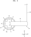
- FIG. 3 is a view illustrating a first side of the battery shown in FIG. 1 .
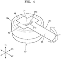
- FIG. 4 is a perspective view illustrating a stress state acting on a first coupling portion of the battery shown in FIG. 1 .
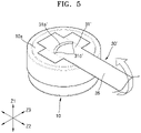
- FIGS. 5 and 6 are perspective views illustrating a stress state acting on a first coupling portion in comparative examples.
- FIGS. 7 and 8 are views illustrating temporary fixing of a first electrode tab when a first coupling portion of the battery shown in FIG. 1 is formed.
- FIG. 9 is a view illustrating a second side of the battery shown in FIG. 1 .
- the battery may include a cell 10 having first and second surfaces 10a and 10b that are opposite to each other along a first axis Z1, and a first electrode tab 30 formed on the first surface 10a of the cell 10.
- the first axis may be an axis in a Z-direction.
- the first electrode tab 30 includes a first coupling piece 31 including a first coupling portion 31a coupled to the first surface 10a of the cell 10 and a first lead-out piece 35 extending from the first coupling piece 31 to the outside of (e.g., to outside a periphery of) the cell 10 along a second axis Z2.
- the second axis may be an axis in an X- or Y-direction.
- the first coupling portion 31a may have a convex arc shape toward (e.g., convex toward or pointing toward) the first lead-out piece 35.
- the first and second surfaces 10a and 10b may be formed opposite to each other along the first axis Z1, and a side surface 10c connects (or extends between) the first surface 10a to the second surface 10b.
- the cell 10 may have the first and second surfaces 10a and 10b, and the side surface 10c may form a circumferential surface connecting (or extending between) the first surface 10a to the second surface 10b.
- the first and second surfaces 10a and 10b may have a circular shape.
- the cell 10 according to an embodiment of the present disclosure may have a slimmed shape in which a height in a first direction (e.g., a direction of the first axis Z1) is relatively smaller than other dimensions (e.g., a diameter D of the first surface 10a).
- the cell 10 according to an embodiment of the present disclosure may have a slim cylindrical shape with a height H that is less than the diameter D of the first surface 10a.
- the aspect ratio of the diameter D of the first surface 10a to the height H of the cell 10 may be in a range of about 5.4:12 to about 5.4:14.
- the aspect ratio of a cell mounting space of a device configured to use the cell 10 as a power source when the aspect ratio is less than the minimum value of 5.4:12, the height of a cell mounting space of a device configured to use the cell 10 as a power source needs to be that much higher. As a result, the height of the set device may not be reduced below a certain amount.
- the aspect ratio of an electrode assembly accommodated in the cell 10 when the aspect ratio is greater than the maximum value of 5.4:14, the aspect ratio of an electrode assembly accommodated in the cell 10 may be excessively increased, and according to an increase in the aspect ratio of the electrode assembly, energy efficiency relative to the same volume may be decreased or excessive manufacturing cost may be incurred in forming an electrode assembly having a correspondingly high aspect ratio.
- the aspect ratio of the cell 10 that is, the aspect ratio of the diameter D of the first surface 10a to the height H, may be in a range of about 5.4:12 to about 5.4:14.
- first and second electrodes 11 and 12 having opposite polarities of the cell 10 may be formed on the first and second surfaces 10a and 10b, respectively.
- the first electrode 11 may be formed at a middle position of the first surface 10a
- the second electrode 12 may be formed from the entire second surface 10b to the side surface 10c and may extend from the side surface 10c to a peripheral position surrounding (e.g., extending around) the middle position of the first surface 10a.
- the middle position of the first surface 10a may refer to a position including a central portion of the first surface 10a or a centrifugal portion of the first surface 10a having a circular shape.
- the peripheral position of the first surface 10a may refer to a position deviated from the central position of the first surface 10a or the centrifugal position of the first surface 10a having a circular shape.
- the first electrode 11 and the second electrode 12 may be formed at different positions on the first surface 10a.
- the first electrode 11 may be formed at the middle position of the first surface 10a
- the second electrode 12 may be formed at the peripheral position of the first surface 10a.
- the first electrode 11 and the second electrode 12 may be spatially spaced apart from each other on the first surface 10a and/or may have an insulating member therebetween, and thus, may be electrically insulated from each other.
- An insulating cap 20 may cover a portion of the first surface 10a of the cell 10, and the insulating cap 20 may allow an electrical connection of the first electrode 11 exposed through a central opening thereof and may provide electrical insulation of the second electrode 12 formed around the first electrode 11.
- the electrical connection of the first electrode 11 may be made through the first surface 10a of the cell 10
- the electrical connection of the second electrode 12 may be made through the second surface 10b of the cell 10.
- the second electrode 12 in addition to the first electrode 11 forming an electrical connection through the first surface 10a of the cell 10, the second electrode 12 may not be exposed through the first surface 10a of the cell 10.
- the insulating cap 20 may cover a portion of (e.g., a peripheral portion of) the first surface 10a so that the second electrode 12 formed at the peripheral position of the first surface 10a is not exposed at the first surface 10a.
- the first electrode tab 30 electrically connected to the first electrode 11 may be formed on the first surface 10a of the cell 10.
- the first electrode tab 30 may be coupled to the middle position of the first surface 10a of the cell 10 to be electrically connected to the first electrode 11.
- the first electrode tab 30 may include the first coupling piece 31 coupled to the first electrode 11 and the first lead-out piece 35 extending forward along the second axis Z2 from the first coupling piece 31.
- the second axis Z2 may refer to a direction crossing (or intersecting) the first axis Z1 and may include one direction and a reverse direction opposite to the one direction along the second axis Z2.
- the second axis Z2 may refer to a direction perpendicular to the first axis Z1.
- a third axis Z3 may refer to a direction crossing (or intersecting) the first and second axes Z1 and Z2.
- the third axis Z3 may refer to a direction perpendicular to the first and second axes Z1 and Z2.
- the first lead-out piece 35 may form a charge/discharge path of the cell 10 while extending along the second axis Z2.
- the first lead-out piece 35 may form a charge/discharge path toward the outside of the cell 10 while extending to the outside of the cell 10 along the second axis Z2 and may extend outside the cell 10 beyond the first surface 10a of the cell 10 along the second axis Z2.
- the first coupling piece 31 may form an electrical connection with the cell 10 and may be coupled to the first surface 10a of the cell 10.
- the first coupling piece 31 may be formed on the first surface 10a and may be arranged entirely on the first surface 10a without departing from (e.g., without extending beyond or outside of a periphery of) the first surface 10a.
- the first coupling piece 31 may include the first coupling portion 31a of an arc shape formed along the third axis Z3.
- the first coupling portion 31a may include (or may be) a welding line formed by laser welding and/or may include a welding line having an arc shape.
- the first coupling portion 31a for forming a coupling between the first coupling piece 31 and the first surface 10a may have an arc shape, and in one embodiment, may have a convex arc shape toward (e.g., convex or pointing toward) the first lead-out piece 35.
- that the first coupling portion 31a has an arc shape may indicate that the first coupling portion 31a does not have a closed shape like a circular shape but has an open arc shape.
- the first coupling portion 31a having an arc shape may increase bonding strength of the first coupling portion 31a in response to (or against) an external impact acting through the first lead-out piece 35 extending to the outside of the cell 10.
- an external impact that tends to lift the first electrode tab 30, which includes the first lead-out piece 35, from the first surface 10a may act on the first lead-out piece 35 extending to the outside of the cell 10 and may cause the first electrode tab 30 to peel off from the first surface 10a.
- the first coupling portion 31a having a convex arc shape toward the first lead-out piece 35 may provide an effective resistance to the first electrode tab 30 peeling-off from the first surface 10a and may improve the impact resistance of the first electrode tab 30.
- the first coupling portion 31a having a convex arc shape toward the first lead-out piece 35 may reduce or prevent stress from being concentrated on any one place of the first coupling portion 31a while gradually propagating stress from, for example, an external impact from a convex curved portion 31c of the first coupling portion 31a, which is closest to the first lead-out piece 35, to both ends of the first coupling portion 31a, which is farthest from the first lead-out piece 35, in response to an external impact that tends to lift the first electrode tab 30 from the first surface 10a. Accordingly, breakage of the first coupling portion 31a due to concentration of stress, or peeling-off according thereto, may be mitigated or prevented.
- the first coupling portion 31a having an arc shape may easily propagate stress in both directions along the third axis Z3 in response to an external impact that tends to peel off the first electrode tab 30.
- an external impact acting through the first lead-out piece 35 may act first on the curved portion 31c adjacent to the first lead-out piece 35, and stress propagation may occur uniformly in both directions of the first coupling portion 31a from the curved portion 31c of the first coupling portion 31a to the third axis Z3, and the stress propagation may occur toward both ends of the first coupling portion 31a.
- a first coupling portion 31a' may have a concave shape toward the first lead-out piece 35.
- an external impact acting through a first lead-out piece 35 may cause peeling-off, which tends to lift a first electrode tab 30' from a first surface 10a, and the external impact may be concentrated on both ends 31c' of the first coupling portion 31a' adjacent to the first lead-out piece 35.
- stress propagation may occur in any one direction along the third axis Z3 from the both ends 31c' of the first coupling portion 31a' adjacent to the first lead-out piece 35, but stress propagation may not uniformly occur in both directions along the third axis Z3.
- the external impact may be concentrated on any one end of the both ends 31 c' adjacent to the first lead-out piece 35.
- stress propagation may occur in only one direction along the third axis Z3 from one end of the first coupling portion 31a' and may not occur in both directions along the third axis Z3.
- the external impact may act randomly, the external impact may not act symmetrically with respect to the first lead-out piece 35 along the third axis Z3 and may be accompanied by distortion biased toward any one of the ends 31c' of the first coupling portion 31a' along the third axis Z3.
- stress propagation may not occur in both directions along the third axis Z3 and may occur in only one direction along the third axis Z3.
- reference numeral 31' denotes the first coupling piece 31' in which the first coupling portion 31a' is formed.
- a first coupling portion 31a" may be formed to have a closed circular (e.g., a circle) shape.
- the first coupling portion 31a" (the comparative example shown in FIG. 6 ) having a closed circular shape is longer than the first coupling portion 31a (the embodiment of the present disclosure shown in FIGS. 1-4 ) having an open arc shape, and thus, may have a higher bonding strength than the first coupling portion 31a.
- the bonding strength thereof may increase but the manufacturing cost for forming the first coupling portion 31a" may increase.
- the first coupling portion 31a having an open arc shape may have a relatively high bonding strength.
- the width thereof along the third axis Z3 decreases, but, on the contrary, when the first coupling portion 31a having a certain length is formed to have an open arc shape, the width thereof along the third axis Z3 increases.
- An external impact acting from the first lead-out piece 35 extending to the outside of the cell 10 may be accompanied by distortion, and with respect to an external impact accompanied by distortion in this way, the first coupling portion 31a, which has an open arc shape and has a relatively large width along the third axis Z3, may have a higher bonding strength than the first coupling portion 31a" of the comparative example.
- the first coupling portion 31a" having a closed circular shape a relatively high stress is applied to a semicircular portion 31a1" facing the first lead-out piece 35 but a relatively low stress is applied to a semicircular portion 31a2" opposite thereto.
- the first coupling portion 31a" having a closed circular shape regardless of the orientation with the first lead-out piece 35 is formed with a uniform bonding strength along the first coupling portion 31a", the semicircular portion 31a2", which overlaps the semicircular portion 31a1" facing the first lead-out piece 35 in the direction of propagation of stress due to external impact, may only slightly contribute to the bonding strength relative to a manufacturing cost. In other words, the improvement in strength of bonding relative to the cost may be small.
- the first coupling portion 31a may be formed to have an arc shape and the width thereof along the third axis Z3 may be at least greater than the width of the lead-out piece 35.
- the width of the first coupling piece 31 in which the first coupling portion 31a is formed may be at least greater than the width of the first lead-out piece 35.
- the first electrode tab 30 may include, along the second axis Z2, a first coupling piece 31, and a first lead-out piece 35 and a first anti-rotation piece 33 formed on both sides (e.g., opposite sides) of the first coupling piece 31.
- the width of the first coupling piece 31 along the third axis Z3 may be formed to be greater than those of the first lead-out piece 35 and the first anti-rotation piece 33.
- an external impact transmitted through the first lead-out piece 35 such as an external impact accompanied by distortion, may intensively act on the positions of both ends of the first coupling portion 31a along the third axis Z3.
- the external impact that is relatively concentrated on one end position may not propagate (or may not substantially propagate) in both directions along the third axis Z3 from one end position of the first coupling portion 31a.
- a first fixing piece 32 may be formed on both sides (e.g., opposite sides) of the first coupling piece 31.
- the first fixing piece 32 may extend from both sides of the first coupling piece 31 along the third axis Z3 and may be formed as a pair on both sides of the first coupling piece 31.
- the first fixing piece 32 may provide a place for temporarily fixing the position of the first electrode tab 30.
- the first coupling portion 31a may be formed by welding between the first coupling piece 31 and the cell 10.
- the position of the first coupling piece 31 may be temporarily fixed with respect to the first surface 10a of the cell 10 while welding is performed on the first surface 10a of the cell 10 and the first coupling piece 31, which overlap each other.
- the cell 10 in the welding of the first coupling portion 31a, the cell 10 may be accommodated in a jig 100 such that the first surface 10a is exposed, the first electrode tab 30 may be placed on the first surface 10a of the cell 10 exposed from the jig 100, and the position of the first electrode tab 30 with respect to the first surface 10a of the cell 10 may be temporarily fixed by pressing the first fixing piece 32 of the first electrode tab 30 against the first surface 10a of the cell 10.
- the first coupling portion 31a for coupling the first surface 10a of the cell 10 to the first electrode tab 30 may be formed.
- the first fixing piece 32 may provide a pressing position at both sides of the first coupling piece 31 so that the position of the first coupling piece 31 is fixed on the first surface 10a of the cell 10.
- the first coupling piece 31, between the pair of first fixing pieces 32 may be fixed in position on the first surface 10a of the cell 10, and the first coupling portion 31a may be formed through (or during) the position fixing therebetween to firmly couple the first coupling piece 31 to the first surface 10a of the cell 10.
- the first fixing piece 32 may be formed as a pair on both sides of the first coupling piece 31 along the third axis Z3. As described above, the first fixing piece 32, formed as a pair on both sides of the first coupling piece 31, may improve the impact resistance of the first electrode tab 30. For example, through the first lead-out piece 35 extending from the first coupling piece 31 to the outside of the cell 10, an external distortion moment with the first lead-out piece 35 as the axis of moment may act on the first coupling piece 31, and the external distortion moment may be transmitted to the first coupling piece 31 along the first lead-out piece 35 to make the first coupling piece 31 deviate from the first surface 10a of the cell 10.
- the first fixing pieces 32 may provide a resistance moment in the opposite direction to the external distortion moment with the first lead-out piece 35 as the axis of moment.
- the first fixing piece 32 may provide resistance to an external distortion moment and may improve the impact resistance characteristics of the first electrode tab 30 against an external impact, such as an external distortion moment.
- the first fixing piece 32 may fix the position of the first coupling piece 31 when the first coupling portion 31a is formed and may also improve the impact resistance characteristics of the first electrode tab 30 by providing effective resistance to an external impact, such as an external distortion moment.
- the first lead-out piece 35 which is at a position in front of (e.g., a front position of) the first coupling piece 31 along the second axis Z2 and extends to a position outside the cell 10, may be formed to form a charging and discharging path of the cell 10.
- the first anti-rotation piece 33 may be formed at a rear position of the first coupling piece 31 along the second axis Z2.
- the first lead-out piece 35 may extend in one direction of the second axis Z2 from the first coupling piece 31, and the first anti-rotation piece 33 may extend from the first coupling piece 31 in a direction opposite to the one direction of the second axis Z2.
- the first anti-rotation piece 33 may be formed together with (e.g., may be integral with) the first coupling piece 31 and the first fixing piece 32 at a rear position of the first electrode tab 30 along the second axis Z2, that is, at a rear position of the first electrode tab 30 in which the first coupling piece 31 and the first fixing piece 32 on both sides of the first coupling piece 31 are arranged, and may be formed at the rearmost position of the first electrode tab 30.
- the first anti-rotation piece 33 and the first fixing piece 32 may be formed together at (e.g., may be integrally formed at) a rear position of the first electrode tab 30 opposite to the first lead-out piece 35 along the second axis Z2 and may temporarily fix the first electrode tab 30.
- a position alignment surface A for temporarily fixing the first electrode tab 30 and preventing movement of the first electrode tab 30 may be formed on adjacent side surfaces of the first anti-rotation piece 33 extending along the second axis Z2 from the first coupling piece 31 and of the first fixing piece 32 extending along the third axis Z3 from the first coupling piece 31. This will be described in more detail later.
- the first anti-rotation piece 33 may temporarily fix the position of the first electrode tab 30 when the first coupling portion 31a, for coupling the first electrode tab 30 to the first surface 10a of the cell 10, is formed.
- the first coupling portion 31a may be formed through welding between the first coupling piece 31 and the cell 10, and the position of the first coupling piece 31 is temporarily fixed with respect to the first surface 10a of the cell 10 during the welding of the first coupling portion 31a (e.g., welding on the first surface 10a of the cell 10 and the first coupling piece 31, which overlap each other). More specifically, referring to FIGS.
- the cell 10 may be accommodated in a jig 100 such that the first surface 10a is exposed, and the first electrode tab 30 may be placed on the first surface 10a of the cell 10 that is exposed from the jig 100 for the welding of the first coupling portion 31a.
- the first electrode tab 30 which is placed on the first surface 10a of the cell 10, and a protruding piece 150, which protrudes, toward the first surface 10a of the cell 10, from a first surface 101 of the jig 100 adjacent to the first surface 10a of the cell 10, are combined with each other, the first electrode tab 30 may be temporarily fixed on the first surface 101 of the jig 100 and the first electrode tab 30 may be temporarily fixed to the cell 10 accommodated in the jig 100.
- the protruding piece 150 on (e.g., formed on) the first surface 101 of the jig 100 in which the cell 10 is accommodated may protrude toward the first surface 10a of the cell 10 that is exposed from the jig 100 and may temporarily fix the position of the first electrode tab 30 while being combined with the first electrode tab 30 placed on the first surface 10a of the cell 10.
- the protruding piece 150 of the jig 100 may be combined with (e.g., may contact or engage with) the first anti-rotation piece 33 of the first electrode tab 30.
- an accommodation groove 150' in which the first anti-rotation piece 33 of the first electrode tab 30 is accommodated, may be formed in the protruding piece 150 of the jig 100.
- the rotational position of the first electrode tab 30 including the first anti-rotation piece 33 may be temporarily fixed on the first surface 10a of the cell 10 by the first anti-rotation piece 33 being constrained within the accommodation groove 150'.
- the combination between the protruding piece 150 of the jig 100 and the first electrode tab 30 may include the fitting between the accommodation groove 150' of the protruding piece 150 and the first anti-rotation piece 33 of the first electrode tab 30, and a physical interference formed when a side surface 150a of the protruding piece 150 outside of the accommodation groove 150' contacts a side surface of the first fixing piece 32 of the first electrode tab 30.
- the protruding piece 150 and the first electrode tab 30 may be formed (e.g., designed) to be combined with each other (e.g., the protruding piece 150 and the first electrode tab 30 may have corresponding or complimentary structures).
- the accommodation groove 150' and the first anti-rotation piece 33 may be combined with each other, and outside of the accommodation groove 150', the side surface 150a of the protruding piece 150 and the side surface of the first fixing piece 32 may contact each other and form a physical interference. In this case, the side surface 150a of the protruding piece 150 and the side surface of the first fixing piece 32 may contact each other.
- the side surface 150a of the protruding piece 150 and the side surface of the first fixing piece 32 do not directly contact each other, that is, they face each other but are spaced apart from each other enough such that the first electrode tab 30 may move slightly before contacting the side surface 150a of the protruding piece 150 , such movement of the first electrode tab 30 may be prevented and the first electrode tab 30 may be temporarily fixed. Therefore, physical interference between the protruding piece 150 and the first fixing piece 32 may refer to direct contact between the protruding piece 150 and the first fixing piece 32 but may also refer to a structure in which the protruding piece 150 and the first fixing piece 32 face each other at a distance from each other and do not directly contact each other.
- the protruding piece 150 of the jig 100 and the first electrode tab 30 may be formed to be combined with each other.
- Components (e.g., the first anti-rotation piece 33 and the first fixing piece 32) of the first electrode tab 30 to be combined with the protruding piece 150 of the jig 100 may be formed at a position adjacent to the first coupling piece 31 and may be formed together at a rear position of the first electrode tab 30 at which the first coupling piece 31 is formed rather than at a front position of the first electrode tab 30 at which the first lead-out piece 35 is formed along the second axis Z2.
- the first anti-rotation piece 33 and the first fixing piece 32 may be combined with (e.g., may be accommodated in) the protruding piece 150 of the jig 100 at a rear position of the first electrode tab 30.
- the combination with the protruding piece 150 of the jig 100 may occur when the protruding piece 150 of the jig 100 contacts the position alignment surface A formed on adjacent side surfaces of the first anti-rotation piece 33 extending along the second axis Z2 from the first coupling piece 31 and the first fixing piece 32 extending along the third axis Z3 from the first coupling piece 31.
- the adjacent side surfaces of the first anti-rotation piece 33 and the first fixing piece 32 may form the position alignment surface A.
- the position alignment surface A at the first anti-rotation piece 33 may form a physical interference with the accommodation groove 150' formed in the protruding piece 150 of the jig 100
- the position alignment surface A at the first fixing piece 32 may form a physical interference with the side surface 150a of the protruding piece 150 of the jig 100.
- the physical interference of the first anti-rotation piece 33 and the first fixing piece 32 may refer to direct physical contact with the protruding piece 150 of the jig 100 or may refer to a structure in which the first anti-rotation piece 33 and the first fixing piece 32 face the protruding piece 150 of the jig 100 with a spacing therebetween and not direct contact with the protruding piece 150 of the jig 100.
- the first anti-rotation piece 33 may temporarily fix the position of the first electrode tab 30 when the first coupling portion 31a for coupling the first electrode tab 30 to the first surface 10a of the cell 10 is formed and may provide resistance to an external impact that tends to lift the first electrode tab 30 from the first surface 10a of the cell 10 even after the first coupling portion 31a is formed.
- an external impact that may cause peeling-off of the first electrode tab 30 by lifting the first electrode tab 30 from the first surface 10a of the cell 10 may act on the lead-out piece 35, which extends beyond the first surface 10a of the cell 10, and the first anti-rotation piece 33 may provide a reverse (or counter) resistance to the external impact.
- the first anti-rotation piece 33 may be formed at a rear position opposite to the front position of the first lead-out piece 35 extending to the outside of the cell 10 along the second axis Z2 and may be formed at a position opposite to the first lead-out piece 35 with respect to the first coupling piece 31 to provide resistance in a reverse direction to offset the external impact acting on the first lead-out piece 35.
- the first electrode tab 30 arranged on the first surface 10a of the cell 10 may include the first lead-out piece 35 extending to the outside of the cell 10 in one direction of the second axis Z2 from the first coupling piece 31 coupled to the first surface 10a of the cell 10, the first fixing piece 32 formed at both sides of the first coupling piece 31, and the first anti-rotation piece 33 extending from the first coupling piece 31 in a direction opposite to the direction of the second axis Z2.
- the first lead-out piece 35, the first coupling piece 31, and the first anti-rotation piece 33 may be formed on one line along the second axis Z2.
- the width of the first coupling piece 31 along the third axis Z3 may be greater than the widths of the first lead-out piece 35 and the first anti-rotation piece 33.
- the width of the first coupling piece 31 may refer to a width of a region where the first coupling portion 31a is formed along the third axis Z3, and the width of the first fixing piece 32 may refer to a width extending along the third direction Z3 from the width of the first coupling piece 31.
- the width of the first anti-rotation piece 33 may be equal to the width of the first lead-out piece 35 along the third direction Z3.
- the first coupling portion 31a may be formed on the first coupling piece 31, and the width of the first coupling portion 31a along the third axis Z3 may be greater than the widths of the first lead-out piece 35 and the first anti-rotation piece 33, and thus, impact resistance to an external impact accompanied by distortion may be improved.
- the width of the first lead-out piece 35 and the width of the first anti-rotation piece 33 along the third axis Z3 may be equal to each other.
- the first lead-out piece 35 and the first anti-rotation piece 33 may be respectively formed at a front position and a rear position of the first coupling piece 31 with respect to the first coupling piece 31.
- the first fixing piece 32 may be arranged at both sides of the first coupling piece 31 along the third axis Z3 cross (or intersecting) the second axis Z2.
- the first electrode tab 30 may be formed to have an overall cross shape extending along the second axis Z2 and the third axis Z3.
- a position where components along the second and third axes Z2 and Z3 intersect with each other may correspond to the position of the first coupling piece 31 formed at a relatively rear position of the first electrode tab 30 along the second axis Z2.
- the first fixing piece 32 extends along the third axis Z3 from the first coupling piece 31 arranged at a rear position of the first electrode tab 30 along the second axis Z2, the first electrode tab 30 having a cross shape, which extends along the second axis Z2 and the third axis Z3, may be formed.
- a first lead wire W1 may be connected to the first electrode tab 30.
- the first lead wire W1 may be connected to an end of the first lead-out piece 35 of the first electrode tab 30.
- the first lead wire W1 may extend along the third axis Z3 from an end of the first lead-out piece 35 extending along the second axis Z2.
- the first lead wire W1 may have the form of a wire having a ductility (e.g., a ductile wire), unlike the first electrode tab 30, which includes (or is) a thin metal plate as a whole, to provide convenient connection with an external device.
- a second electrode tab 40 may be arranged on the second surface 10b of the cell 10.
- the second electrode tab 40 may be formed to have substantially the same shape as the first electrode tab 30.
- the second electrode tab 40 may include a second coupling piece 41 including a second coupling portion 41a coupled on a second surface 10b of a cell 10, a second lead-out piece 45 extending to the outside of the cell 10 beyond the second surface 10b of the cell 10 in one direction of the second axis Z2 from the second coupling piece 41, a second fixing piece 42 extending from the second coupling piece 41 along the third axis Z3 and formed on both sides (e.g., opposite sides) of the second coupling piece 41, and a second anti-rotation piece 43 extending in a direction opposite to the direction of the second axis Z2 from the second coupling piece 41.
- the first and second electrode tabs 30 and 40 may be formed to have different orientations and/or to have different shapes.
- the first and second electrode tabs 30 and 40 may be arranged in different orientations on the first and second surfaces 10a and 10b of the cell 10, respectively, while being formed to have substantially the same shape.
- the first and second electrode tabs 30 and 40 may be formed to have an overall cross shape while extending in directions crossing (or intersecting) each other and may be arranged in different orientations while being arranged on the first and second surfaces 10a and 10b of the cell 10, respectively.
- the second electrode tab 40 may be have substantially the same shape and may be in same orientation as the first electrode tab 30.
- Technical details of the second coupling piece 41, the second fixing piece 42, the second lead-out piece 45, and the second anti-rotation piece 43 of the second electrode tab 40, and a second lead wire W2 connected to the second electrode tab 40 may be the same as those of the first coupling piece 31, the first fixing piece 32, the first lead-out piece 35, and the first anti-rotation piece 33 of the first electrode tab 30, and the first lead wire W1 connected to the first electrode tab 30, and thus, repeated descriptions thereof will be omitted.
- FIG. 10 is a view illustrating a battery according to another embodiment of the present disclosure.
- the battery may include a cell 10 and a first electrode tab 130 arranged on a first surface 10a of the cell 10.
- the first electrode tab 130 may include a first coupling piece 131 in which a first coupling portion 131a coupled to the first surface 10a of the cell 10 is formed.
- the first coupling portion 131a may include a main coupling portion 1311 having a convex arc shape toward a first lead-out piece 135, extending in one direction of a second axis Z2, and an auxiliary coupling portion 1312 having a convex arc shape toward a first anti-rotation piece 133, extending in a direction opposite to the one direction of the second axis Z2.
- the main coupling portion 1311 and the auxiliary coupling portion 1312 may be formed to have convex arc shapes in a direction toward the first lead-out piece 135 and a direction toward the first anti-rotation piece 133, respectively, and may include convex arc-shaped portions directly facing the main coupling portion 1311 and the auxiliary coupling portion 1312, respectively.
- the main coupling portion 1311 may disperse stress, caused by the external impact, along an arc shape that is convex toward the first lead-out piece 135, and thus, may prevent the first electrode tab 130 from peeling off from the first surface 10a of the cell 10 due to the external impact and may improve the impact resistance of the first electrode tab 130 against the external impact.
- the auxiliary coupling portion 1312 may disperse stress, caused by the external impact, along an arc shape that is convex toward the first anti-rotation piece 133, and thus, may prevent the first electrode tab 130 from peeling off from the first surface 10a of the cell 10 due to the external impact and may improve the impact resistance of the first electrode tab 130 against the external impact.
- the main coupling portion 1311 and the auxiliary coupling portion 1312 may be formed to have arc shapes convex toward the first lead-out piece 135 and the first anti-rotation piece 133 extending in opposite directions from the first coupling piece 131, respectively, and thus, may improve impact resistance against an external impact acting from the first lead-out piece 135 and the first anti-rotation piece 133.
- the main coupling portion 1311 and the auxiliary coupling portion 1312 may be formed to have arc shapes convex toward the first lead-out piece 135 and the first anti-rotation piece 133 formed at positions opposite to the first coupling piece 131, respectively, and thus, may have arc shapes having opposite orientations, respectively.
- the main coupling portion 1311 and the auxiliary coupling portion 1312 may formed to have different lengths.
- that the main coupling portion 1311 and the auxiliary coupling portion 1312 are formed to have different lengths may denote that the total length of the main coupling portion 1311 extending along the arc shape thereof may be different from the total length of the auxiliary coupling portion 1312 extending along the arc shape thereof.
- the main coupling portion 1311 and the auxiliary coupling portion 1312 may be formed to respectively have arc shapes having different curvatures.
- the main coupling portion 1311 may have an arc shape having a first curvature
- the auxiliary coupling portion 1312 may have an arc shape having a second curvature.
- the length of an arc according to the first curvature forming the main coupling portion 1311 may be different from the length of an arc according to the second curvature forming the auxiliary coupling portion 1312, and the length of the arc of the main coupling portion 1311 may be greater than the length of the arc of the auxiliary coupling portion 1312.
- the main coupling portion 1311 may be formed to have a length greater than that of the auxiliary coupling portion 1312 for receiving an external impact acting on the first anti-rotation piece 133 arranged inside the cell 10, and the main coupling portion 1311 may provide a relatively higher bonding strength than that provided by the auxiliary coupling portion 1312.
- the main coupling portion 1311 and the auxiliary coupling portion 1312 may be formed to have arc shapes according to different curvatures, respectively.
- the main coupling portion 1311 may have an arc shape according to a first curvature
- the auxiliary coupling portion 1312 may have an arc shape according to a second curvature.
- the first curvature of the main coupling portion 1311 may be less than the second curvature of the auxiliary coupling portion 1312.
- the main coupling portion 1311 may be formed to be flatter than the auxiliary coupling portion 1312.
- the first radius of curvature of the arc shape of the main coupling portion 1311 may be greater than the second radius of curvature of the arc shape of the auxiliary coupling portion 1312.
- the main coupling portion 1311 may be formed wider along the third axis Z3 than the auxiliary coupling portion 1312 for receiving an external impact acting on the first anti-rotation piece 133 arranged inside the cell 10.
- the main coupling portion 1311 may be formed wider along the third axis Z3 in a relatively flat shape than the auxiliary coupling portion 1312 as the first curvature of the main coupling portion 1311 is less than the second curvature of the auxiliary coupling portion 1312. Accordingly, with respect to an external impact including an external distortion moment, a bonding strength provided by the main coupling portion 1311 may be relatively higher than a bonding strength provided by the auxiliary coupling portion 1312.
- the width of the main coupling portion 1311 along the third axis Z3 may be greater than the width of the auxiliary coupling portion 1312.
- the width of the main coupling portion 1311 along the third axis Z3 may be greater than the width of the first lead-out piece 135 or the first anti-rotation piece 133
- the width of the auxiliary coupling portion 1312 along the third axis Z3 may be less than the width of the first lead-out piece 135 or the first anti-rotation piece 133.
- a second electrode tab 140 may be arranged on the second surface 10b of the cell 10 and may have substantially the same structure as the first electrode tab 130 arranged on the first surface 10a of the cell 10.
- a second coupling portion 141a coupled to the second surface 10b of the cell 10 may include a main coupling portion 1411 and an auxiliary coupling portion 1412 having respective convex arc shapes toward a second lead-out piece 145 and a second anti-rotation piece 143 extending in one direction of the second axis Z2 and a direction opposite to the one direction of the second axis Z2, respectively.
- the main coupling portion 1411 and the auxiliary coupling portion 1412 may respectively have an arc shape with a first curvature and an arc shape with a second curvature that is different from the first curvature, and the length of the main coupling portion 1411 along the first curvature may be different from the length of the auxiliary coupling portion 1412 along the second curvature.
- a reference numeral 132 and a reference numeral 142 denote a fixing piece formed on the first electrode tab 130 and a fixing piece formed on the second electrode tab 140, respectively.
- a battery having an electrode tab connected to an electrode of a cell having improved impact resistance characteristics is provided.
- a coupling portion for forming a coupling between a cell and an electrode tab is formed to have a convex arc shape toward a lead-out piece extending from an electrode of the cell forming a charge and discharge path of the cell, the coupling portion may prevent stress from being concentrated on any one place of the coupling portion while gradually propagating stress from to an external impact from a convex curved portion of the coupling portion to both ends of the coupling portion. Accordingly, breakage of the coupling portion due to concentration of stress, or peeling-off according thereto, may be mitigated or prevented.
Landscapes
- Chemical & Material Sciences (AREA)
- Chemical Kinetics & Catalysis (AREA)
- Electrochemistry (AREA)
- General Chemical & Material Sciences (AREA)
- Engineering & Computer Science (AREA)
- Manufacturing & Machinery (AREA)
- Connection Of Batteries Or Terminals (AREA)
Abstract
A battery includes: a cell having a first surface and a second surface opposite to each other along a first axis; and a first electrode tab on the first surface of the cell. The first electrode tab includes: a first coupling piece including a first coupling portion coupled to the first surface of the cell; and a first lead-out piece extending from the first coupling piece outside a periphery of the cell along a second axis. The first coupling portion has a convex arc shape toward the first lead-out piece.
Description
- Aspects of embodiments of the present disclosure relate to a battery.
- Generally, secondary batteries are designed to be charged and discharged, unlike primary batteries that are not designed to be charged. Secondary batteries are used as energy sources for mobile devices, electric vehicles, hybrid vehicles, electric bicycles, uninterruptible power supplies, and so on and are used in the form of a single battery or in the form of a module in which multiple batteries are connected to each other and bundled together as a unit depending on the type of external device(s) to which it is to be applied.
- One or more embodiments of the present disclosure include a battery in which an electrode tab connected to an electrode of a cell has improved impact resistance characteristics.
- Additional aspects and features of the present disclosure will be set forth, in part, in the description which follows and, in part, will be apparent from the description or may be learned by the practice of the described embodiments of the present disclosure.
- According to an embodiment of the present disclosure, a battery includes: a cell having a first surface and a second surface opposite to each other along a first axis; and a first electrode tab on the first surface of the cell. The first electrode tab includes: a first coupling piece including a first coupling portion coupled to the first surface of the cell; and a first lead-out piece extending from the first coupling piece outside a periphery of the cell along a second axis. The first coupling portion has a convex arc shape toward the first lead-out piece. The arc shape may be formed along a third axis crossing the first and second axes. The first coupling portion may include (or may be) a welding line formed by laser welding or may include a welding line having an arc shape.
- The first coupling portion may have an open arc shape.
- A width of the first coupling piece may be greater than a width of the first lead-out piece along a third axis crossing the first and second axes. The width of the first coupling piece may refer to a width of a region where the first coupling portion is formed along the third axis.
- A width, along the third axis, of the arc shape first coupling portion may be greater than a width of the first lead-out piece.
- The first electrode tab may further include a first fixing piece extending from the first coupling piece along a third axis crossing the second axis.
- The first fixing piece may be a pair at both sides of the first coupling piece along the third axis.
- The first lead-out piece may extend in one direction of the second axis from the first coupling piece, and the first electrode tab may further include a first anti-rotation piece extending from the first coupling piece in a direction opposite to the one direction of the second axis.
- The first lead-out piece and the first anti-rotation piece may respectively be at a front position and a rear position opposite to each other along the second axes with respect to the first coupling piece.
- A position alignment surface may be on adjacent side surfaces of the first anti-rotation piece and the first fixing piece.
- The first coupling portion may include: a main coupling portion having a convex arc shape toward the first lead-out piece; and an auxiliary coupling portion having a convex arc shape toward the first anti-rotation piece.
- A length along the convex arc shape of the main coupling portion may be greater than a length along the convex arc shape of the auxiliary coupling portion.
- The main coupling portion may have an arc shape with a first curvature, and the auxiliary coupling portion may have an arc shape with a second curvature that is different from the first curvature.
- The first curvature of the main coupling portion may be less than the second curvature of the auxiliary coupling portion.
- A width of the main coupling portion in a third axis crossing the first and second axes may be greater than a width of the first lead-out piece, and a width of the auxiliary coupling portion may be less than the width of the first lead-out piece.
- The first lead-out piece, the first coupling piece, and the first anti-rotation piece, which may be sequentially arranged along the second axis, and a first fixing piece extending from the first coupling piece along a third axis crossing the first and second axes may have an overall cross shape.
- With respect to the first lead-out piece, the first coupling piece, and the first anti-rotation piece, which may be sequentially arranged along the second axis, a width of the first coupling piece along the third axis may be greater than widths of the first lead-out piece and the first anti-rotation piece.
- A width, along the third axis, of the arc shaped first coupling portion may be greater than the widths of the first lead-out piece and the first anti-rotation piece.
- A first lead wire extending along a third axis crossing the second axis may be connected to the first lead-out piece.
- The battery may further include a second electrode tab arranged on the second surface of the cell.
- The second electrode tab may include: a second coupling piece including a second coupling portion coupled to the second surface of the cell; and a second lead-out piece extending from the second coupling piece to outside a periphery of the cell along the second axis. The second coupling portion may have a convex arc shape toward the second lead-out piece.
- The above and other aspects and features of embodiments of the present disclosure will be more apparent from the following description, taken in conjunction with the accompanying drawings, in which:
-
FIG. 1 is a perspective view of a battery according to an embodiment of the present disclosure; -
FIG. 2 is an exploded perspective view of the battery shown inFIG. 1 ; -
FIG. 3 is a view illustrating a first side of the battery shown inFIG. 1 ; -
FIG. 4 is a perspective view illustrating a stress state acting on a first coupling portion of the battery shown inFIG. 1 ; -
FIGS. 5 and6 are perspective views illustrating a stress state acting on a first coupling portion in comparative examples; -
FIGS. 7 and8 are views illustrating temporary fixing of a first electrode tab when a first coupling portion of the battery shown inFIG. 1 is formed; -
FIG. 9 is a view illustrating a second side of the battery shown inFIG. 1 ; and -
FIG. 10 is a view illustrating a battery according to another embodiment of the present disclosure. - Reference will now be made, in detail, to embodiments, examples of which are illustrated in the accompanying drawings. Like reference numerals refer to like elements throughout. The described embodiments may have different forms and should not be construed as being limited to the descriptions set forth herein. Accordingly, the embodiments are merely described below, by referring to the figures, to explain aspects and features of the present description. As used herein, the term "and/or" includes any and all combinations of one or more of the associated listed items. Expressions, such as "at least one of," when preceding a list of elements, modify the entire list of elements and do not modify the individual elements of the list. Further, the use of "may" when describing embodiments of the present disclosure relates to "one or more embodiments of the present disclosure." As used herein, the terms "use," "using," and "used" may be considered synonymous with the terms "utilize," "utilizing," and "utilized," respectively. As used herein, the terms "substantially," "about," and similar terms are used as terms of approximation and not as terms of degree, and are intended to account for the inherent variations in measured or calculated values that would be recognized by those of ordinary skill in the art.
- It will be understood that when an element or layer is referred to as being "on," "connected to," or "coupled to" another element or layer, it may be directly on, connected, or coupled to the other element or layer or one or more intervening elements or layers may also be present. When an element or layer is referred to as being "directly on," "directly connected to," or "directly coupled to" another element or layer, there are no intervening elements or layers present. For example, when a first element is described as being "coupled" or "connected" to a second element, the first element may be directly coupled or connected to the second element or the first element may be indirectly coupled or connected to the second element via one or more intervening elements.
- will be understood that, although the terms first, second, third, etc. may be used herein to describe various elements, components, regions, layers, and/or sections, these elements, components, regions, layers, and/or sections should not be limited by these terms. These terms are used to distinguish one element, component, region, layer, or section from another element, component, region, layer, or section. Thus, a first element, component, region, layer, or section discussed below could be termed a second element, component, region, layer, or section without departing from the teachings of example embodiments.
- Spatially relative terms, such as "beneath," "below," "lower," "above," "upper," and the like, may be used herein for ease of description to describe one element or feature's relationship to another element(s) or feature(s) as illustrated in the figures. It will be understood that the spatially relative terms are intended to encompass different orientations of the device in use or operation in addition to the orientation depicted in the figures. For example, if the device in the figures is turned over, elements described as "below" or "beneath" other elements or features would then be oriented "above" or "over" the other elements or features. Thus, the term "below" may encompass both an orientation of above and below. The device may be otherwise oriented (rotated 90 degrees or at other orientations), and the spatially relative descriptors used herein should be interpreted accordingly.
- The terminology used herein is for the purpose of describing embodiments of the present disclosure and is not intended to be limiting of the present disclosure. As used herein, the singular forms "a" and "an" are intended to include the plural forms as well, unless the context clearly indicates otherwise. It will be further understood that the terms "includes," "including," "comprises," and/or "comprising," when used in this specification, specify the presence of stated features, integers, steps, operations, elements, and/or components but do not preclude the presence or addition of one or more other features, integers, steps, operations, elements, components, and/or groups thereof.
- Hereinafter, a battery according to embodiments of the present disclosure will be described with reference to the accompanying drawings.
-
FIG. 1 is a perspective view of a battery according to an embodiment of the present disclosure.FIG. 2 is an exploded perspective view of the battery shown inFIG. 1 .FIG. 3 is a view illustrating a first side of the battery shown inFIG. 1 .FIG. 4 is a perspective view illustrating a stress state acting on a first coupling portion of the battery shown inFIG. 1 .FIGS. 5 and6 are perspective views illustrating a stress state acting on a first coupling portion in comparative examples.FIGS. 7 and8 are views illustrating temporary fixing of a first electrode tab when a first coupling portion of the battery shown inFIG. 1 is formed.FIG. 9 is a view illustrating a second side of the battery shown inFIG. 1 . - Referring to
FIGS. 1 to 3 , the battery according to an embodiment of the present disclosure may include acell 10 having first andsecond surfaces first electrode tab 30 formed on thefirst surface 10a of thecell 10. The first axis may be an axis in a Z-direction. Thefirst electrode tab 30 includes afirst coupling piece 31 including afirst coupling portion 31a coupled to thefirst surface 10a of thecell 10 and a first lead-out piece 35 extending from thefirst coupling piece 31 to the outside of (e.g., to outside a periphery of) thecell 10 along a second axis Z2. The second axis may be an axis in an X- or Y-direction. Thefirst coupling portion 31a may have a convex arc shape toward (e.g., convex toward or pointing toward) the first lead-out piece 35. - The first and
second surfaces side surface 10c connects (or extends between) thefirst surface 10a to thesecond surface 10b. For example, thecell 10 according to an embodiment of the present disclosure may have the first andsecond surfaces side surface 10c may form a circumferential surface connecting (or extending between) thefirst surface 10a to thesecond surface 10b. In an embodiment of the present disclosure, the first andsecond surfaces cell 10 according to an embodiment of the present disclosure may have a slimmed shape in which a height in a first direction (e.g., a direction of the first axis Z1) is relatively smaller than other dimensions (e.g., a diameter D of thefirst surface 10a). For example, thecell 10 according to an embodiment of the present disclosure may have a slim cylindrical shape with a height H that is less than the diameter D of thefirst surface 10a. For example, the aspect ratio of the diameter D of thefirst surface 10a to the height H of thecell 10 may be in a range of about 5.4:12 to about 5.4:14. In an embodiment of the present disclosure, when the aspect ratio is less than the minimum value of 5.4:12, the height of a cell mounting space of a device configured to use thecell 10 as a power source needs to be that much higher. As a result, the height of the set device may not be reduced below a certain amount. Conversely, when the aspect ratio is greater than the maximum value of 5.4:14, the aspect ratio of an electrode assembly accommodated in thecell 10 may be excessively increased, and according to an increase in the aspect ratio of the electrode assembly, energy efficiency relative to the same volume may be decreased or excessive manufacturing cost may be incurred in forming an electrode assembly having a correspondingly high aspect ratio. Accordingly, in an embodiment of the present disclosure, the aspect ratio of thecell 10, that is, the aspect ratio of the diameter D of thefirst surface 10a to the height H, may be in a range of about 5.4:12 to about 5.4:14. - Referring to
FIG. 2 , first andsecond electrodes cell 10 may be formed on the first andsecond surfaces first electrode 11 may be formed at a middle position of thefirst surface 10a, and thesecond electrode 12 may be formed from the entiresecond surface 10b to theside surface 10c and may extend from theside surface 10c to a peripheral position surrounding (e.g., extending around) the middle position of thefirst surface 10a. In an embodiment of the present disclosure, the middle position of thefirst surface 10a may refer to a position including a central portion of thefirst surface 10a or a centrifugal portion of thefirst surface 10a having a circular shape. In addition, the peripheral position of thefirst surface 10a may refer to a position deviated from the central position of thefirst surface 10a or the centrifugal position of thefirst surface 10a having a circular shape. Thefirst electrode 11 and thesecond electrode 12 may be formed at different positions on thefirst surface 10a. For example, thefirst electrode 11 may be formed at the middle position of thefirst surface 10a, and thesecond electrode 12 may be formed at the peripheral position of thefirst surface 10a. In such an embodiment, thefirst electrode 11 and thesecond electrode 12 may be spatially spaced apart from each other on thefirst surface 10a and/or may have an insulating member therebetween, and thus, may be electrically insulated from each other. - An insulating
cap 20 may cover a portion of thefirst surface 10a of thecell 10, and the insulatingcap 20 may allow an electrical connection of thefirst electrode 11 exposed through a central opening thereof and may provide electrical insulation of thesecond electrode 12 formed around thefirst electrode 11. In an embodiment of the present disclosure, the electrical connection of thefirst electrode 11 may be made through thefirst surface 10a of thecell 10, and the electrical connection of thesecond electrode 12 may be made through thesecond surface 10b of thecell 10. In such an embodiment, in addition to thefirst electrode 11 forming an electrical connection through thefirst surface 10a of thecell 10, thesecond electrode 12 may not be exposed through thefirst surface 10a of thecell 10. The insulatingcap 20 may cover a portion of (e.g., a peripheral portion of) thefirst surface 10a so that thesecond electrode 12 formed at the peripheral position of thefirst surface 10a is not exposed at thefirst surface 10a. - Referring to
FIG. 3 , thefirst electrode tab 30 electrically connected to thefirst electrode 11 may be formed on thefirst surface 10a of thecell 10. Thefirst electrode tab 30 may be coupled to the middle position of thefirst surface 10a of thecell 10 to be electrically connected to thefirst electrode 11. For example, thefirst electrode tab 30 may include thefirst coupling piece 31 coupled to thefirst electrode 11 and the first lead-out piece 35 extending forward along the second axis Z2 from thefirst coupling piece 31. The second axis Z2 may refer to a direction crossing (or intersecting) the first axis Z1 and may include one direction and a reverse direction opposite to the one direction along the second axis Z2. In an embodiment of the present disclosure, the second axis Z2 may refer to a direction perpendicular to the first axis Z1. As described below, a third axis Z3 may refer to a direction crossing (or intersecting) the first and second axes Z1 and Z2. For example, the third axis Z3 may refer to a direction perpendicular to the first and second axes Z1 and Z2. - The first lead-
out piece 35 may form a charge/discharge path of thecell 10 while extending along the second axis Z2. For example, the first lead-out piece 35 may form a charge/discharge path toward the outside of thecell 10 while extending to the outside of thecell 10 along the second axis Z2 and may extend outside thecell 10 beyond thefirst surface 10a of thecell 10 along the second axis Z2. - The
first coupling piece 31 may form an electrical connection with thecell 10 and may be coupled to thefirst surface 10a of thecell 10. Thefirst coupling piece 31 may be formed on thefirst surface 10a and may be arranged entirely on thefirst surface 10a without departing from (e.g., without extending beyond or outside of a periphery of) thefirst surface 10a. - Referring to
FIGS. 3 and4 , thefirst coupling piece 31 may include thefirst coupling portion 31a of an arc shape formed along the third axis Z3. Thefirst coupling portion 31a may include (or may be) a welding line formed by laser welding and/or may include a welding line having an arc shape. In an embodiment of the present disclosure, thefirst coupling portion 31a for forming a coupling between thefirst coupling piece 31 and thefirst surface 10a may have an arc shape, and in one embodiment, may have a convex arc shape toward (e.g., convex or pointing toward) the first lead-out piece 35. In such an embodiment, that thefirst coupling portion 31a has an arc shape may indicate that thefirst coupling portion 31a does not have a closed shape like a circular shape but has an open arc shape. - As such, the
first coupling portion 31a having an arc shape may increase bonding strength of thefirst coupling portion 31a in response to (or against) an external impact acting through the first lead-out piece 35 extending to the outside of thecell 10. For example, an external impact that tends to lift thefirst electrode tab 30, which includes the first lead-out piece 35, from thefirst surface 10a may act on the first lead-out piece 35 extending to the outside of thecell 10 and may cause thefirst electrode tab 30 to peel off from thefirst surface 10a. Thefirst coupling portion 31a having a convex arc shape toward the first lead-out piece 35 may provide an effective resistance to thefirst electrode tab 30 peeling-off from thefirst surface 10a and may improve the impact resistance of thefirst electrode tab 30. - The
first coupling portion 31a having a convex arc shape toward the first lead-out piece 35 may reduce or prevent stress from being concentrated on any one place of thefirst coupling portion 31a while gradually propagating stress from, for example, an external impact from a convexcurved portion 31c of thefirst coupling portion 31a, which is closest to the first lead-out piece 35, to both ends of thefirst coupling portion 31a, which is farthest from the first lead-out piece 35, in response to an external impact that tends to lift thefirst electrode tab 30 from thefirst surface 10a. Accordingly, breakage of thefirst coupling portion 31a due to concentration of stress, or peeling-off according thereto, may be mitigated or prevented. For example, in an embodiment of the present disclosure, thefirst coupling portion 31a having an arc shape may easily propagate stress in both directions along the third axis Z3 in response to an external impact that tends to peel off thefirst electrode tab 30. In an embodiment of the present disclosure, because thefirst coupling portion 31a has a convex arc shape toward the first lead-out piece 35, an external impact acting through the first lead-out piece 35 may act first on thecurved portion 31c adjacent to the first lead-out piece 35, and stress propagation may occur uniformly in both directions of thefirst coupling portion 31a from thecurved portion 31c of thefirst coupling portion 31a to the third axis Z3, and the stress propagation may occur toward both ends of thefirst coupling portion 31a. - In a comparative example shown in
FIG. 5 , which is to be contrasted with embodiments of the present disclosure, afirst coupling portion 31a' may have a concave shape toward the first lead-out piece 35. In this case, an external impact acting through a first lead-out piece 35 may cause peeling-off, which tends to lift a first electrode tab 30' from afirst surface 10a, and the external impact may be concentrated on bothends 31c' of thefirst coupling portion 31a' adjacent to the first lead-out piece 35. In this case, stress propagation may occur in any one direction along the third axis Z3 from the both ends 31c' of thefirst coupling portion 31a' adjacent to the first lead-out piece 35, but stress propagation may not uniformly occur in both directions along the third axis Z3. For example, the external impact may be concentrated on any one end of the both ends 31 c' adjacent to the first lead-out piece 35. In this case, stress propagation may occur in only one direction along the third axis Z3 from one end of thefirst coupling portion 31a' and may not occur in both directions along the third axis Z3. Because the external impact may act randomly, the external impact may not act symmetrically with respect to the first lead-out piece 35 along the third axis Z3 and may be accompanied by distortion biased toward any one of theends 31c' of thefirst coupling portion 31a' along the third axis Z3. In this case, at one end of thefirst coupling portion 31a', which is subjected to relatively intense external impact, stress propagation may not occur in both directions along the third axis Z3 and may occur in only one direction along the third axis Z3. On the other hand, in the embodiment of the present disclosure shown inFIG. 4 , even against an external impact acting asymmetrically, for example, an external impact accompanied by distortion, stress propagation may occur in both directions along the third axis Z3 from thecurved portion 31c of thefirst coupling portion 31a closest to the first lead-out piece 35, and the stress propagation may occur uniformly in both directions along the third axis Z3. InFIG. 5 , reference numeral 31' denotes the first coupling piece 31' in which thefirst coupling portion 31a' is formed. - In another comparative example shown in
FIG. 6 , which is to be contrasted with an embodiment of the present disclosure, afirst coupling portion 31a" may be formed to have a closed circular (e.g., a circle) shape. Thefirst coupling portion 31a" (the comparative example shown inFIG. 6 ) having a closed circular shape is longer than thefirst coupling portion 31a (the embodiment of the present disclosure shown inFIGS. 1-4 ) having an open arc shape, and thus, may have a higher bonding strength than thefirst coupling portion 31a. In this case, when the length of thefirst coupling portion 31a" increases, the bonding strength thereof may increase but the manufacturing cost for forming thefirst coupling portion 31a" may increase. With respect to the comparative example including thefirst coupling portion 31a" having a closed circular shape, shown inFIG. 6 , and the embodiment of the present disclosure including thefirst coupling portion 31a having an open arc shape, shown inFIG. 4 , when comparing the bonding strengths of thefirst coupling portion 31a" and thefirst coupling portion 31a, which have the same length, thefirst coupling portion 31a having an open arc shape may have a relatively high bonding strength. For example, when thefirst coupling portion 31a" having a certain length is formed to have a closed circular shape, the width thereof along the third axis Z3 decreases, but, on the contrary, when thefirst coupling portion 31a having a certain length is formed to have an open arc shape, the width thereof along the third axis Z3 increases. An external impact acting from the first lead-out piece 35 extending to the outside of thecell 10 may be accompanied by distortion, and with respect to an external impact accompanied by distortion in this way, thefirst coupling portion 31a, which has an open arc shape and has a relatively large width along the third axis Z3, may have a higher bonding strength than thefirst coupling portion 31a" of the comparative example. In addition, as in the comparative example shown inFIG. 6 , in thefirst coupling portion 31a" having a closed circular shape, a relatively high stress is applied to a semicircular portion 31a1" facing the first lead-out piece 35 but a relatively low stress is applied to a semicircular portion 31a2" opposite thereto. Because thefirst coupling portion 31a" having a closed circular shape regardless of the orientation with the first lead-out piece 35 is formed with a uniform bonding strength along thefirst coupling portion 31a", the semicircular portion 31a2", which overlaps the semicircular portion 31a1" facing the first lead-out piece 35 in the direction of propagation of stress due to external impact, may only slightly contribute to the bonding strength relative to a manufacturing cost. In other words, the improvement in strength of bonding relative to the cost may be small. - In the embodiment of the present disclosure shown in
FIG. 4 , thefirst coupling portion 31a may be formed to have an arc shape and the width thereof along the third axis Z3 may be at least greater than the width of the lead-out piece 35. For example, the width of thefirst coupling piece 31 in which thefirst coupling portion 31a is formed may be at least greater than the width of the first lead-out piece 35. As described below, thefirst electrode tab 30 may include, along the second axis Z2, afirst coupling piece 31, and a first lead-out piece 35 and afirst anti-rotation piece 33 formed on both sides (e.g., opposite sides) of thefirst coupling piece 31. The width of thefirst coupling piece 31 along the third axis Z3 may be formed to be greater than those of the first lead-out piece 35 and thefirst anti-rotation piece 33. When the width of thefirst coupling portion 31a along the third axis Z3 is equal to or less than that of the first lead-out piece 35, an external impact transmitted through the first lead-out piece 35, such as an external impact accompanied by distortion, may intensively act on the positions of both ends of thefirst coupling portion 31a along the third axis Z3. In this case, the external impact that is relatively concentrated on one end position may not propagate (or may not substantially propagate) in both directions along the third axis Z3 from one end position of thefirst coupling portion 31a. - Referring to
FIG. 3 , afirst fixing piece 32 may be formed on both sides (e.g., opposite sides) of thefirst coupling piece 31. Thefirst fixing piece 32 may extend from both sides of thefirst coupling piece 31 along the third axis Z3 and may be formed as a pair on both sides of thefirst coupling piece 31. When thefirst coupling portion 31a for coupling thefirst electrode tab 30 to thefirst surface 10a of thecell 10 is formed, thefirst fixing piece 32 may provide a place for temporarily fixing the position of thefirst electrode tab 30. In an embodiment of the present disclosure, thefirst coupling portion 31a may be formed by welding between thefirst coupling piece 31 and thecell 10. In such an embodiment, the position of thefirst coupling piece 31 may be temporarily fixed with respect to thefirst surface 10a of thecell 10 while welding is performed on thefirst surface 10a of thecell 10 and thefirst coupling piece 31, which overlap each other. For example, referring toFIGS. 7 and8 , in the welding of thefirst coupling portion 31a, thecell 10 may be accommodated in ajig 100 such that thefirst surface 10a is exposed, thefirst electrode tab 30 may be placed on thefirst surface 10a of thecell 10 exposed from thejig 100, and the position of thefirst electrode tab 30 with respect to thefirst surface 10a of thecell 10 may be temporarily fixed by pressing thefirst fixing piece 32 of thefirst electrode tab 30 against thefirst surface 10a of thecell 10. In addition, by performing welding, for example, laser welding, on thefirst surface 10a of thecell 10 and thefirst electrode tab 30, which are fixed in position with respect to each other in this way, thefirst coupling portion 31a for coupling thefirst surface 10a of thecell 10 to thefirst electrode tab 30 may be formed. For example, thefirst fixing piece 32 may provide a pressing position at both sides of thefirst coupling piece 31 so that the position of thefirst coupling piece 31 is fixed on thefirst surface 10a of thecell 10. In addition, by pressing and fixing thefirst fixing piece 32 on thefirst surface 10a of thecell 10, thefirst coupling piece 31, between the pair of first fixingpieces 32, may be fixed in position on thefirst surface 10a of thecell 10, and thefirst coupling portion 31a may be formed through (or during) the position fixing therebetween to firmly couple thefirst coupling piece 31 to thefirst surface 10a of thecell 10. - Referring to
FIG. 3 , thefirst fixing piece 32 may be formed as a pair on both sides of thefirst coupling piece 31 along the third axis Z3. As described above, thefirst fixing piece 32, formed as a pair on both sides of thefirst coupling piece 31, may improve the impact resistance of thefirst electrode tab 30. For example, through the first lead-out piece 35 extending from thefirst coupling piece 31 to the outside of thecell 10, an external distortion moment with the first lead-out piece 35 as the axis of moment may act on thefirst coupling piece 31, and the external distortion moment may be transmitted to thefirst coupling piece 31 along the first lead-out piece 35 to make thefirst coupling piece 31 deviate from thefirst surface 10a of thecell 10. In this case, thefirst fixing pieces 32, formed as a pair on both sides of thefirst coupling piece 31, may provide a resistance moment in the opposite direction to the external distortion moment with the first lead-out piece 35 as the axis of moment. For example, thefirst fixing piece 32 may provide resistance to an external distortion moment and may improve the impact resistance characteristics of thefirst electrode tab 30 against an external impact, such as an external distortion moment. Thus, thefirst fixing piece 32, according to an embodiment of the present disclosure, may fix the position of thefirst coupling piece 31 when thefirst coupling portion 31a is formed and may also improve the impact resistance characteristics of thefirst electrode tab 30 by providing effective resistance to an external impact, such as an external distortion moment. - The first lead-
out piece 35, which is at a position in front of (e.g., a front position of) thefirst coupling piece 31 along the second axis Z2 and extends to a position outside thecell 10, may be formed to form a charging and discharging path of thecell 10. Thefirst anti-rotation piece 33 may be formed at a rear position of thefirst coupling piece 31 along the second axis Z2. For example, the first lead-out piece 35 may extend in one direction of the second axis Z2 from thefirst coupling piece 31, and thefirst anti-rotation piece 33 may extend from thefirst coupling piece 31 in a direction opposite to the one direction of the second axis Z2. Thefirst anti-rotation piece 33 may be formed together with (e.g., may be integral with) thefirst coupling piece 31 and thefirst fixing piece 32 at a rear position of thefirst electrode tab 30 along the second axis Z2, that is, at a rear position of thefirst electrode tab 30 in which thefirst coupling piece 31 and thefirst fixing piece 32 on both sides of thefirst coupling piece 31 are arranged, and may be formed at the rearmost position of thefirst electrode tab 30. As described below, thefirst anti-rotation piece 33 and thefirst fixing piece 32 may be formed together at (e.g., may be integrally formed at) a rear position of thefirst electrode tab 30 opposite to the first lead-out piece 35 along the second axis Z2 and may temporarily fix thefirst electrode tab 30. A position alignment surface A for temporarily fixing thefirst electrode tab 30 and preventing movement of thefirst electrode tab 30 may be formed on adjacent side surfaces of thefirst anti-rotation piece 33 extending along the second axis Z2 from thefirst coupling piece 31 and of thefirst fixing piece 32 extending along the third axis Z3 from thefirst coupling piece 31. This will be described in more detail later. - The
first anti-rotation piece 33 may temporarily fix the position of thefirst electrode tab 30 when thefirst coupling portion 31a, for coupling thefirst electrode tab 30 to thefirst surface 10a of thecell 10, is formed. In an embodiment of the present disclosure, thefirst coupling portion 31a may be formed through welding between thefirst coupling piece 31 and thecell 10, and the position of thefirst coupling piece 31 is temporarily fixed with respect to thefirst surface 10a of thecell 10 during the welding of thefirst coupling portion 31a (e.g., welding on thefirst surface 10a of thecell 10 and thefirst coupling piece 31, which overlap each other). More specifically, referring toFIGS. 7 and8 , thecell 10 may be accommodated in ajig 100 such that thefirst surface 10a is exposed, and thefirst electrode tab 30 may be placed on thefirst surface 10a of thecell 10 that is exposed from thejig 100 for the welding of thefirst coupling portion 31a. In addition, because thefirst electrode tab 30, which is placed on thefirst surface 10a of thecell 10, and aprotruding piece 150, which protrudes, toward thefirst surface 10a of thecell 10, from afirst surface 101 of thejig 100 adjacent to thefirst surface 10a of thecell 10, are combined with each other, thefirst electrode tab 30 may be temporarily fixed on thefirst surface 101 of thejig 100 and thefirst electrode tab 30 may be temporarily fixed to thecell 10 accommodated in thejig 100. - In an embodiment of the present disclosure, the protruding
piece 150 on (e.g., formed on) thefirst surface 101 of thejig 100 in which thecell 10 is accommodated may protrude toward thefirst surface 10a of thecell 10 that is exposed from thejig 100 and may temporarily fix the position of thefirst electrode tab 30 while being combined with thefirst electrode tab 30 placed on thefirst surface 10a of thecell 10. - In an embodiment of the present disclosure, the protruding
piece 150 of thejig 100 may be combined with (e.g., may contact or engage with) thefirst anti-rotation piece 33 of thefirst electrode tab 30. In some embodiments, an accommodation groove 150', in which thefirst anti-rotation piece 33 of thefirst electrode tab 30 is accommodated, may be formed in the protrudingpiece 150 of thejig 100. In addition, by fitting thefirst anti-rotation piece 33 in the accommodation groove 150' of the protrudingpiece 150, arbitrary (or undesired or unintended) rotation of thefirst anti-rotation piece 33 in the accommodation groove 150' may be prevented. The rotational position of thefirst electrode tab 30 including thefirst anti-rotation piece 33 may be temporarily fixed on thefirst surface 10a of thecell 10 by thefirst anti-rotation piece 33 being constrained within the accommodation groove 150'. - In an embodiment of the present disclosure, the combination between the protruding
piece 150 of thejig 100 and thefirst electrode tab 30 may include the fitting between the accommodation groove 150' of the protrudingpiece 150 and thefirst anti-rotation piece 33 of thefirst electrode tab 30, and a physical interference formed when aside surface 150a of the protrudingpiece 150 outside of the accommodation groove 150' contacts a side surface of thefirst fixing piece 32 of thefirst electrode tab 30. For example, the protrudingpiece 150 and thefirst electrode tab 30 may be formed (e.g., designed) to be combined with each other (e.g., the protrudingpiece 150 and thefirst electrode tab 30 may have corresponding or complimentary structures). Inside the accommodation groove 150' formed in the protrudingpiece 150, the accommodation groove 150' and thefirst anti-rotation piece 33 may be combined with each other, and outside of the accommodation groove 150', theside surface 150a of the protrudingpiece 150 and the side surface of thefirst fixing piece 32 may contact each other and form a physical interference. In this case, theside surface 150a of the protrudingpiece 150 and the side surface of thefirst fixing piece 32 may contact each other. In various embodiments of the present disclosure, even if theside surface 150a of the protrudingpiece 150 and the side surface of thefirst fixing piece 32 do not directly contact each other, that is, they face each other but are spaced apart from each other enough such that thefirst electrode tab 30 may move slightly before contacting theside surface 150a of the protrudingpiece 150 , such movement of thefirst electrode tab 30 may be prevented and thefirst electrode tab 30 may be temporarily fixed. Therefore, physical interference between the protrudingpiece 150 and thefirst fixing piece 32 may refer to direct contact between the protrudingpiece 150 and thefirst fixing piece 32 but may also refer to a structure in which the protrudingpiece 150 and thefirst fixing piece 32 face each other at a distance from each other and do not directly contact each other. - As described above, the protruding
piece 150 of thejig 100 and thefirst electrode tab 30 may be formed to be combined with each other. Components (e.g., thefirst anti-rotation piece 33 and the first fixing piece 32) of thefirst electrode tab 30 to be combined with the protrudingpiece 150 of thejig 100 may be formed at a position adjacent to thefirst coupling piece 31 and may be formed together at a rear position of thefirst electrode tab 30 at which thefirst coupling piece 31 is formed rather than at a front position of thefirst electrode tab 30 at which the first lead-out piece 35 is formed along the second axis Z2. - In an embodiment of the present disclosure, the
first anti-rotation piece 33 and thefirst fixing piece 32 may be combined with (e.g., may be accommodated in) the protrudingpiece 150 of thejig 100 at a rear position of thefirst electrode tab 30. In such an embodiment, the combination with the protrudingpiece 150 of thejig 100 may occur when the protrudingpiece 150 of thejig 100 contacts the position alignment surface A formed on adjacent side surfaces of thefirst anti-rotation piece 33 extending along the second axis Z2 from thefirst coupling piece 31 and thefirst fixing piece 32 extending along the third axis Z3 from thefirst coupling piece 31. For example, the adjacent side surfaces of thefirst anti-rotation piece 33 and thefirst fixing piece 32 may form the position alignment surface A. The position alignment surface A at thefirst anti-rotation piece 33 may form a physical interference with the accommodation groove 150' formed in the protrudingpiece 150 of thejig 100, and the position alignment surface A at thefirst fixing piece 32 may form a physical interference with theside surface 150a of the protrudingpiece 150 of thejig 100. In this example, the physical interference of thefirst anti-rotation piece 33 and thefirst fixing piece 32 may refer to direct physical contact with the protrudingpiece 150 of thejig 100 or may refer to a structure in which thefirst anti-rotation piece 33 and thefirst fixing piece 32 face the protrudingpiece 150 of thejig 100 with a spacing therebetween and not direct contact with the protrudingpiece 150 of thejig 100. - Referring to
FIG. 3 , thefirst anti-rotation piece 33 may temporarily fix the position of thefirst electrode tab 30 when thefirst coupling portion 31a for coupling thefirst electrode tab 30 to thefirst surface 10a of thecell 10 is formed and may provide resistance to an external impact that tends to lift thefirst electrode tab 30 from thefirst surface 10a of thecell 10 even after thefirst coupling portion 31a is formed. For example, in an embodiment of the present disclosure, an external impact that may cause peeling-off of thefirst electrode tab 30 by lifting thefirst electrode tab 30 from thefirst surface 10a of thecell 10 may act on the lead-out piece 35, which extends beyond thefirst surface 10a of thecell 10, and thefirst anti-rotation piece 33 may provide a reverse (or counter) resistance to the external impact. For example, thefirst anti-rotation piece 33 may be formed at a rear position opposite to the front position of the first lead-out piece 35 extending to the outside of thecell 10 along the second axis Z2 and may be formed at a position opposite to the first lead-out piece 35 with respect to thefirst coupling piece 31 to provide resistance in a reverse direction to offset the external impact acting on the first lead-out piece 35. - As described above, the
first electrode tab 30 arranged on thefirst surface 10a of thecell 10 may include the first lead-out piece 35 extending to the outside of thecell 10 in one direction of the second axis Z2 from thefirst coupling piece 31 coupled to thefirst surface 10a of thecell 10, thefirst fixing piece 32 formed at both sides of thefirst coupling piece 31, and thefirst anti-rotation piece 33 extending from thefirst coupling piece 31 in a direction opposite to the direction of the second axis Z2. In an embodiment of the present disclosure, in thefirst electrode tabs 30, the first lead-out piece 35, thefirst coupling piece 31, and thefirst anti-rotation piece 33 may be formed on one line along the second axis Z2. In such an embodiment, the width of thefirst coupling piece 31 along the third axis Z3 may be greater than the widths of the first lead-out piece 35 and thefirst anti-rotation piece 33. For example, in an embodiment of the present disclosure, the width of thefirst coupling piece 31 may refer to a width of a region where thefirst coupling portion 31a is formed along the third axis Z3, and the width of thefirst fixing piece 32 may refer to a width extending along the third direction Z3 from the width of thefirst coupling piece 31. In an embodiment of the present disclosure, the width of thefirst anti-rotation piece 33 may be equal to the width of the first lead-out piece 35 along the third direction Z3. For example, thefirst coupling portion 31a may be formed on thefirst coupling piece 31, and the width of thefirst coupling portion 31a along the third axis Z3 may be greater than the widths of the first lead-out piece 35 and thefirst anti-rotation piece 33, and thus, impact resistance to an external impact accompanied by distortion may be improved. In addition, the width of the first lead-out piece 35 and the width of thefirst anti-rotation piece 33 along the third axis Z3 may be equal to each other. - The first lead-
out piece 35 and thefirst anti-rotation piece 33 may be respectively formed at a front position and a rear position of thefirst coupling piece 31 with respect to thefirst coupling piece 31. In addition, thefirst fixing piece 32 may be arranged at both sides of thefirst coupling piece 31 along the third axis Z3 cross (or intersecting) the second axis Z2. As such, thefirst electrode tab 30 may be formed to have an overall cross shape extending along the second axis Z2 and the third axis Z3. In such an embodiment, a position where components along the second and third axes Z2 and Z3 intersect with each other may correspond to the position of thefirst coupling piece 31 formed at a relatively rear position of thefirst electrode tab 30 along the second axis Z2. In addition, because thefirst fixing piece 32 extends along the third axis Z3 from thefirst coupling piece 31 arranged at a rear position of thefirst electrode tab 30 along the second axis Z2, thefirst electrode tab 30 having a cross shape, which extends along the second axis Z2 and the third axis Z3, may be formed. - A first lead wire W1 (see, e.g.,
FIG. 3 ) may be connected to thefirst electrode tab 30. For example, the first lead wire W1 may be connected to an end of the first lead-out piece 35 of thefirst electrode tab 30. The first lead wire W1 may extend along the third axis Z3 from an end of the first lead-out piece 35 extending along the second axis Z2. For example, the first lead wire W1 may have the form of a wire having a ductility (e.g., a ductile wire), unlike thefirst electrode tab 30, which includes (or is) a thin metal plate as a whole, to provide convenient connection with an external device. - Referring to
FIG. 9 , asecond electrode tab 40 may be arranged on thesecond surface 10b of thecell 10. Thesecond electrode tab 40 may be formed to have substantially the same shape as thefirst electrode tab 30. For example, in an embodiment of the present disclosure, thesecond electrode tab 40 may include asecond coupling piece 41 including asecond coupling portion 41a coupled on asecond surface 10b of acell 10, a second lead-out piece 45 extending to the outside of thecell 10 beyond thesecond surface 10b of thecell 10 in one direction of the second axis Z2 from thesecond coupling piece 41, asecond fixing piece 42 extending from thesecond coupling piece 41 along the third axis Z3 and formed on both sides (e.g., opposite sides) of thesecond coupling piece 41, and asecond anti-rotation piece 43 extending in a direction opposite to the direction of the second axis Z2 from thesecond coupling piece 41. - In various embodiments of the present disclosure, the first and
second electrode tabs second electrode tabs second surfaces cell 10, respectively, while being formed to have substantially the same shape. For example, the first andsecond electrode tabs second surfaces cell 10, respectively. - In an embodiment of the present disclosure, the
second electrode tab 40 may be have substantially the same shape and may be in same orientation as thefirst electrode tab 30. Technical details of thesecond coupling piece 41, thesecond fixing piece 42, the second lead-out piece 45, and thesecond anti-rotation piece 43 of thesecond electrode tab 40, and a second lead wire W2 connected to thesecond electrode tab 40, may be the same as those of thefirst coupling piece 31, thefirst fixing piece 32, the first lead-out piece 35, and thefirst anti-rotation piece 33 of thefirst electrode tab 30, and the first lead wire W1 connected to thefirst electrode tab 30, and thus, repeated descriptions thereof will be omitted. -
FIG. 10 is a view illustrating a battery according to another embodiment of the present disclosure. The battery may include acell 10 and afirst electrode tab 130 arranged on afirst surface 10a of thecell 10. Thefirst electrode tab 130 may include afirst coupling piece 131 in which afirst coupling portion 131a coupled to thefirst surface 10a of thecell 10 is formed. In this embodiment, thefirst coupling portion 131a may include amain coupling portion 1311 having a convex arc shape toward a first lead-out piece 135, extending in one direction of a second axis Z2, and anauxiliary coupling portion 1312 having a convex arc shape toward afirst anti-rotation piece 133, extending in a direction opposite to the one direction of the second axis Z2. In an embodiment of the present disclosure, themain coupling portion 1311 and theauxiliary coupling portion 1312 may be formed to have convex arc shapes in a direction toward the first lead-out piece 135 and a direction toward thefirst anti-rotation piece 133, respectively, and may include convex arc-shaped portions directly facing themain coupling portion 1311 and theauxiliary coupling portion 1312, respectively. - To respond to an external impact acting from the first lead-
out piece 135 extending to the outside of thecell 10 in one direction of the second axis Z2, themain coupling portion 1311 may disperse stress, caused by the external impact, along an arc shape that is convex toward the first lead-out piece 135, and thus, may prevent thefirst electrode tab 130 from peeling off from thefirst surface 10a of thecell 10 due to the external impact and may improve the impact resistance of thefirst electrode tab 130 against the external impact. - To respond to an external impact acting from the
first anti-rotation piece 133 extending in a direction opposite to the direction of the second axis Z2, theauxiliary coupling portion 1312 may disperse stress, caused by the external impact, along an arc shape that is convex toward thefirst anti-rotation piece 133, and thus, may prevent thefirst electrode tab 130 from peeling off from thefirst surface 10a of thecell 10 due to the external impact and may improve the impact resistance of thefirst electrode tab 130 against the external impact. - The
main coupling portion 1311 and theauxiliary coupling portion 1312 may be formed to have arc shapes convex toward the first lead-out piece 135 and thefirst anti-rotation piece 133 extending in opposite directions from thefirst coupling piece 131, respectively, and thus, may improve impact resistance against an external impact acting from the first lead-out piece 135 and thefirst anti-rotation piece 133. In this way, themain coupling portion 1311 and theauxiliary coupling portion 1312 may be formed to have arc shapes convex toward the first lead-out piece 135 and thefirst anti-rotation piece 133 formed at positions opposite to thefirst coupling piece 131, respectively, and thus, may have arc shapes having opposite orientations, respectively. In an embodiment of the present disclosure, themain coupling portion 1311 and theauxiliary coupling portion 1312 may formed to have different lengths. In such an embodiment, that themain coupling portion 1311 and theauxiliary coupling portion 1312 are formed to have different lengths may denote that the total length of themain coupling portion 1311 extending along the arc shape thereof may be different from the total length of theauxiliary coupling portion 1312 extending along the arc shape thereof. As described below, themain coupling portion 1311 and theauxiliary coupling portion 1312 may be formed to respectively have arc shapes having different curvatures. For example, themain coupling portion 1311 may have an arc shape having a first curvature, and theauxiliary coupling portion 1312 may have an arc shape having a second curvature. In such an embodiment, the length of an arc according to the first curvature forming themain coupling portion 1311 may be different from the length of an arc according to the second curvature forming theauxiliary coupling portion 1312, and the length of the arc of themain coupling portion 1311 may be greater than the length of the arc of theauxiliary coupling portion 1312. Because themain coupling portion 1311 receives an external impact acting on the first lead-out piece 135 extending to the outside of thecell 10, themain coupling portion 1311 may be formed to have a length greater than that of theauxiliary coupling portion 1312 for receiving an external impact acting on thefirst anti-rotation piece 133 arranged inside thecell 10, and themain coupling portion 1311 may provide a relatively higher bonding strength than that provided by theauxiliary coupling portion 1312. - The
main coupling portion 1311 and theauxiliary coupling portion 1312 may be formed to have arc shapes according to different curvatures, respectively. For example, themain coupling portion 1311 may have an arc shape according to a first curvature, and theauxiliary coupling portion 1312 may have an arc shape according to a second curvature. In such an embodiment, the first curvature of themain coupling portion 1311 may be less than the second curvature of theauxiliary coupling portion 1312. For example, themain coupling portion 1311 may be formed to be flatter than theauxiliary coupling portion 1312. In other words, the first radius of curvature of the arc shape of themain coupling portion 1311 may be greater than the second radius of curvature of the arc shape of theauxiliary coupling portion 1312. Because themain coupling portion 1311 receives an external impact acting on the first lead-out piece 135 extending to the outside of thecell 10, themain coupling portion 1311 may be formed wider along the third axis Z3 than theauxiliary coupling portion 1312 for receiving an external impact acting on thefirst anti-rotation piece 133 arranged inside thecell 10. In addition, themain coupling portion 1311 may be formed wider along the third axis Z3 in a relatively flat shape than theauxiliary coupling portion 1312 as the first curvature of themain coupling portion 1311 is less than the second curvature of theauxiliary coupling portion 1312. Accordingly, with respect to an external impact including an external distortion moment, a bonding strength provided by themain coupling portion 1311 may be relatively higher than a bonding strength provided by theauxiliary coupling portion 1312. - In an embodiment of the present disclosure, the width of the
main coupling portion 1311 along the third axis Z3 may be greater than the width of theauxiliary coupling portion 1312. For example, the width of themain coupling portion 1311 along the third axis Z3 may be greater than the width of the first lead-out piece 135 or thefirst anti-rotation piece 133, and the width of theauxiliary coupling portion 1312 along the third axis Z3 may be less than the width of the first lead-out piece 135 or thefirst anti-rotation piece 133. - A
second electrode tab 140 may be arranged on thesecond surface 10b of thecell 10 and may have substantially the same structure as thefirst electrode tab 130 arranged on thefirst surface 10a of thecell 10. For example, as shown inFIG. 10 , asecond coupling portion 141a coupled to thesecond surface 10b of thecell 10 may include amain coupling portion 1411 and anauxiliary coupling portion 1412 having respective convex arc shapes toward a second lead-out piece 145 and asecond anti-rotation piece 143 extending in one direction of the second axis Z2 and a direction opposite to the one direction of the second axis Z2, respectively. Themain coupling portion 1411 and theauxiliary coupling portion 1412 may respectively have an arc shape with a first curvature and an arc shape with a second curvature that is different from the first curvature, and the length of themain coupling portion 1411 along the first curvature may be different from the length of theauxiliary coupling portion 1412 along the second curvature. InFIG. 10 , areference numeral 132 and areference numeral 142 denote a fixing piece formed on thefirst electrode tab 130 and a fixing piece formed on thesecond electrode tab 140, respectively. - According to embodiments of the present disclosure, a battery having an electrode tab connected to an electrode of a cell having improved impact resistance characteristics is provided.
- According to an embodiment of the present disclosure, because a coupling portion for forming a coupling between a cell and an electrode tab is formed to have a convex arc shape toward a lead-out piece extending from an electrode of the cell forming a charge and discharge path of the cell, the coupling portion may prevent stress from being concentrated on any one place of the coupling portion while gradually propagating stress from to an external impact from a convex curved portion of the coupling portion to both ends of the coupling portion. Accordingly, breakage of the coupling portion due to concentration of stress, or peeling-off according thereto, may be mitigated or prevented.
- It should be understood that embodiments described herein should be considered in a descriptive sense and not for purposes of limitation. Descriptions of features or aspects within each embodiment should typically be considered as available for other similar features or aspects in other embodiments. While one or more embodiments have been described with reference to the figures, it will be understood by those of ordinary skill in the art that various changes in form and details may be made therein without departing from the scope of the disclosure as defined by the following claims and their equivalents.
Claims (15)
- A battery comprising:a cell (10) having a first surface (10a) and a second surface (10b) opposite to each other along a first axis (Z1); anda first electrode tab (30) on the first surface (10a) of the cell, the first electrode tab comprising:a first coupling piece (31) comprising a first coupling portion (31a) coupled to the first surface of the cell; anda first lead-out piece (35) extending from the first coupling piece (31) toward outside of a periphery of the cell (10) along a second axis (Z2),wherein the first coupling portion has a convex arc shape toward the first lead-out piece (35).
- The battery of claim 1, wherein the first coupling portion (31a) has an open arc shape.
- The battery of claim 1 or 2, wherein a width of the first coupling piece (31) is greater than a width of the first lead-out piece (35) along a third axis (Z3) crossing the first and second axes (Z1 and Z2).
- The battery of any of the preceding claims, wherein a circumferential length of an arc of the arc shaped first coupling portion (31) is greater than a width of the first lead-out piece (35) along a third axis (Z3) crossing the first and second axes.
- The battery of any of the preceding claims, wherein the first electrode tab further comprises a first fixing piece (32) extending from the first coupling piece (31) along a third axis (Z3) crossing the first and second axes.
- The battery of claim 5, wherein the first fixing piece (32) is formed as a pair on both sides of the first coupling piece (31) along the third axis (Z3).
- The battery of any of the preceding claims, wherein the first lead-out piece (35) extends in one direction of the second axis (Z2) from the first coupling piece (31), and
wherein the first electrode tab further comprises a first anti-rotation piece extending from the first coupling piece (31) in a direction opposite to the one direction of the second axis (Z2). - The battery of claim 7, wherein the first lead-out piece (35) is disposed opposite to the first anti-rotation piece (33) with respect to the first coupling piece (31) along the second axis , and/or, wherein a position alignment surface is on adjacent side surfaces of the first anti-rotation piece (33) and the first fixing piece (32).
- The battery of claim 7 or 8, wherein the first coupling portion comprises:a main coupling portion (1311) having a convex arc shape toward the first lead-out piece (35); andan auxiliary coupling portion (1312) having a convex arc shape toward the first anti-rotation piece (33), and/or wherein a length along the convex arc shape of the main coupling portion (1311) is greater than a length along the convex arc shape of the auxiliary coupling portion (1312).
- The battery of claim 9, wherein the main coupling portion (1311) has an arc shape with a first curvature, and
wherein the auxiliary coupling portion (1312) has an arc shape with a second curvature that is different from the first curvature, and/or wherein the first curvature of the main coupling portion (1311) is smaller than the second curvature of the auxiliary coupling portion (1312). - The battery of claim 9 or 10, wherein a width of the main coupling portion (1311) in the third axis (Z3) is greater than a width of the first lead-out piece (135), and
wherein a width of the auxiliary coupling portion (1312) is smaller than the width of the first lead-out piece (135). - The battery of claim 7, wherein the first lead-out piece (35), the first coupling piece (31), and the first anti-rotation piece (33), which are sequentially arranged along the second axis (Z2) are disposed perpendicular to the first fixing piece (32) .
- The battery of claim 12, wherein, a width of the first coupling piece (31) is greater than widths of the first lead-out piece and the first anti-rotation piece along the third axis (Z3), and/or
wherein a circumferential length of an arc of the arc shaped first coupling portion (31) is greater than the widths of the first lead-out piece (35) and the first anti-rotation piece along the third axis (Z3). - The battery of any of the preceding claims, wherein a first lead wire (W1) extending along a third axis (Z3) crossing the first and second axes (Z1 and Z2) is connected to the first lead-out piece.
- The battery of any of the preceding claims, further comprising a second electrode tab (40) arranged on the second surface (10b) of the cell (10), and/or wherein the second electrode tab (40) comprises:a second coupling piece (41) comprising a second coupling portion (41a) coupled to the second surface of the cell; anda second lead-out piece (45) extending from the second coupling piece toward outside of a periphery of the cell along the second axis, andwherein the second coupling portion (41a) has a convex arc shape toward the second lead-out piece.
Applications Claiming Priority (1)
| Application Number | Priority Date | Filing Date | Title |
|---|---|---|---|
| KR1020210048019A KR102951292B1 (en) | 2021-04-13 | 2021-04-13 | Battery |
Publications (1)
| Publication Number | Publication Date |
|---|---|
| EP4075576A1 true EP4075576A1 (en) | 2022-10-19 |
Family
ID=81307888
Family Applications (1)
| Application Number | Title | Priority Date | Filing Date |
|---|---|---|---|
| EP22168145.5A Pending EP4075576A1 (en) | 2021-04-13 | 2022-04-13 | Battery |
Country Status (4)
| Country | Link |
|---|---|
| US (1) | US20220328937A1 (en) |
| EP (1) | EP4075576A1 (en) |
| KR (1) | KR102951292B1 (en) |
| CN (1) | CN115207575B (en) |
Families Citing this family (1)
| Publication number | Priority date | Publication date | Assignee | Title |
|---|---|---|---|---|
| US20240322400A1 (en) * | 2023-03-26 | 2024-09-26 | Samsung Sdi Co., Ltd. | Battery |
Citations (3)
| Publication number | Priority date | Publication date | Assignee | Title |
|---|---|---|---|---|
| JPH10125357A (en) * | 1996-10-23 | 1998-05-15 | Citizen Watch Co Ltd | Power storage block structure for rechargeable electronic devices |
| EP3657572A1 (en) * | 2017-07-18 | 2020-05-27 | Maxell Holdings, Ltd. | Battery with external terminals |
| JP3231495U (en) * | 2020-09-16 | 2021-04-08 | ヴァルタ マイクロバッテリー ゲゼルシャフト ミット ベシュレンクテル ハフツング | Electrochemical cell with contact lag |
Family Cites Families (4)
| Publication number | Priority date | Publication date | Assignee | Title |
|---|---|---|---|---|
| JP4901017B2 (en) * | 2001-04-24 | 2012-03-21 | 日立マクセルエナジー株式会社 | Flat nonaqueous electrolyte secondary battery with lead terminals |
| KR102415121B1 (en) * | 2017-09-22 | 2022-06-30 | 삼성에스디아이 주식회사 | Battery pack |
| US11522254B2 (en) * | 2017-10-25 | 2022-12-06 | Blue Energy Co., Ltd. | Energy storage apparatus |
| US11881598B2 (en) * | 2019-09-30 | 2024-01-23 | Oberon Technologies Inc. | Apparatus and method for connecting electrical components |
-
2021
- 2021-04-13 KR KR1020210048019A patent/KR102951292B1/en active Active
-
2022
- 2022-04-12 US US17/658,970 patent/US20220328937A1/en active Pending
- 2022-04-13 CN CN202210386330.3A patent/CN115207575B/en active Active
- 2022-04-13 EP EP22168145.5A patent/EP4075576A1/en active Pending
Patent Citations (3)
| Publication number | Priority date | Publication date | Assignee | Title |
|---|---|---|---|---|
| JPH10125357A (en) * | 1996-10-23 | 1998-05-15 | Citizen Watch Co Ltd | Power storage block structure for rechargeable electronic devices |
| EP3657572A1 (en) * | 2017-07-18 | 2020-05-27 | Maxell Holdings, Ltd. | Battery with external terminals |
| JP3231495U (en) * | 2020-09-16 | 2021-04-08 | ヴァルタ マイクロバッテリー ゲゼルシャフト ミット ベシュレンクテル ハフツング | Electrochemical cell with contact lag |
Also Published As
| Publication number | Publication date |
|---|---|
| KR20220141649A (en) | 2022-10-20 |
| CN115207575A (en) | 2022-10-18 |
| CN115207575B (en) | 2025-04-04 |
| KR102951292B1 (en) | 2026-04-09 |
| US20220328937A1 (en) | 2022-10-13 |
Similar Documents
| Publication | Publication Date | Title |
|---|---|---|
| CN101826629B (en) | Rechargeable battery | |
| EP2461392B1 (en) | Battery module | |
| CN113966562B (en) | rechargeable battery | |
| US20120135283A1 (en) | Rechargeable battery | |
| US20080131768A1 (en) | Cylindrical secondary battery | |
| EP2385566A1 (en) | Rechargeable battery assembly | |
| US20050287427A1 (en) | Battery module | |
| CN116231179B (en) | End cap assembly, battery and energy storage device | |
| US11942660B2 (en) | Battery pack | |
| US20130040191A1 (en) | Rechargeable battery | |
| EP1808915B1 (en) | Conductive plate and secondary battery pack using conductive plate | |
| EP4075576A1 (en) | Battery | |
| EP4020696A1 (en) | Connection member connected to electrode lead by physical coupling, and battery cell stack comprising same | |
| US10840561B2 (en) | Battery pack | |
| KR20180013671A (en) | Rechargeable battery | |
| KR20200072458A (en) | Pouch type Secondary battery | |
| US12537217B2 (en) | Rechargeable battery | |
| CN115207530A (en) | Battery with a battery cell | |
| JP4683855B2 (en) | Pack battery | |
| US12620681B2 (en) | Battery | |
| US20250202072A1 (en) | Battery, battery module and battery pack | |
| US20230402725A1 (en) | Battery | |
| EP4443581A1 (en) | Battery | |
| KR100958648B1 (en) | Electrode assembly and secondary battery using same | |
| CN118712673A (en) | Battery Pack |
Legal Events
| Date | Code | Title | Description |
|---|---|---|---|
| PUAI | Public reference made under article 153(3) epc to a published international application that has entered the european phase |
Free format text: ORIGINAL CODE: 0009012 |
|
| STAA | Information on the status of an ep patent application or granted ep patent |
Free format text: STATUS: REQUEST FOR EXAMINATION WAS MADE |
|
| 17P | Request for examination filed |
Effective date: 20220413 |
|
| AK | Designated contracting states |
Kind code of ref document: A1 Designated state(s): AL AT BE BG CH CY CZ DE DK EE ES FI FR GB GR HR HU IE IS IT LI LT LU LV MC MK MT NL NO PL PT RO RS SE SI SK SM TR |
|
| STAA | Information on the status of an ep patent application or granted ep patent |
Free format text: STATUS: EXAMINATION IS IN PROGRESS |
|
| 17Q | First examination report despatched |
Effective date: 20250212 |