EP4075384A1 - Methods and systems for determining pre-determined points in an input image - Google Patents
Methods and systems for determining pre-determined points in an input image Download PDFInfo
- Publication number
- EP4075384A1 EP4075384A1 EP21168656.3A EP21168656A EP4075384A1 EP 4075384 A1 EP4075384 A1 EP 4075384A1 EP 21168656 A EP21168656 A EP 21168656A EP 4075384 A1 EP4075384 A1 EP 4075384A1
- Authority
- EP
- European Patent Office
- Prior art keywords
- implemented method
- determined points
- computer implemented
- points
- shifted
- Prior art date
- Legal status (The legal status is an assumption and is not a legal conclusion. Google has not performed a legal analysis and makes no representation as to the accuracy of the status listed.)
- Granted
Links
Images



Classifications
-
- G—PHYSICS
- G06—COMPUTING OR CALCULATING; COUNTING
- G06T—IMAGE DATA PROCESSING OR GENERATION, IN GENERAL
- G06T7/00—Image analysis
- G06T7/80—Analysis of captured images to determine intrinsic or extrinsic camera parameters, i.e. camera calibration
-
- G—PHYSICS
- G06—COMPUTING OR CALCULATING; COUNTING
- G06T—IMAGE DATA PROCESSING OR GENERATION, IN GENERAL
- G06T7/00—Image analysis
- G06T7/70—Determining position or orientation of objects or cameras
- G06T7/73—Determining position or orientation of objects or cameras using feature-based methods
-
- G—PHYSICS
- G06—COMPUTING OR CALCULATING; COUNTING
- G06N—COMPUTING ARRANGEMENTS BASED ON SPECIFIC COMPUTATIONAL MODELS
- G06N3/00—Computing arrangements based on biological models
- G06N3/02—Neural networks
- G06N3/08—Learning methods
-
- G—PHYSICS
- G06—COMPUTING OR CALCULATING; COUNTING
- G06T—IMAGE DATA PROCESSING OR GENERATION, IN GENERAL
- G06T7/00—Image analysis
- G06T7/10—Segmentation; Edge detection
- G06T7/13—Edge detection
-
- G—PHYSICS
- G06—COMPUTING OR CALCULATING; COUNTING
- G06T—IMAGE DATA PROCESSING OR GENERATION, IN GENERAL
- G06T7/00—Image analysis
- G06T7/80—Analysis of captured images to determine intrinsic or extrinsic camera parameters, i.e. camera calibration
- G06T7/85—Stereo camera calibration
-
- G—PHYSICS
- G06—COMPUTING OR CALCULATING; COUNTING
- G06T—IMAGE DATA PROCESSING OR GENERATION, IN GENERAL
- G06T2207/00—Indexing scheme for image analysis or image enhancement
- G06T2207/20—Special algorithmic details
- G06T2207/20021—Dividing image into blocks, subimages or windows
-
- G—PHYSICS
- G06—COMPUTING OR CALCULATING; COUNTING
- G06T—IMAGE DATA PROCESSING OR GENERATION, IN GENERAL
- G06T2207/00—Indexing scheme for image analysis or image enhancement
- G06T2207/20—Special algorithmic details
- G06T2207/20081—Training; Learning
-
- G—PHYSICS
- G06—COMPUTING OR CALCULATING; COUNTING
- G06T—IMAGE DATA PROCESSING OR GENERATION, IN GENERAL
- G06T2207/00—Indexing scheme for image analysis or image enhancement
- G06T2207/20—Special algorithmic details
- G06T2207/20084—Artificial neural networks [ANN]
-
- G—PHYSICS
- G06—COMPUTING OR CALCULATING; COUNTING
- G06T—IMAGE DATA PROCESSING OR GENERATION, IN GENERAL
- G06T2207/00—Indexing scheme for image analysis or image enhancement
- G06T2207/30—Subject of image; Context of image processing
- G06T2207/30204—Marker
- G06T2207/30208—Marker matrix
-
- G—PHYSICS
- G06—COMPUTING OR CALCULATING; COUNTING
- G06T—IMAGE DATA PROCESSING OR GENERATION, IN GENERAL
- G06T2207/00—Indexing scheme for image analysis or image enhancement
- G06T2207/30—Subject of image; Context of image processing
- G06T2207/30244—Camera pose
Definitions
- the present disclosure relates to methods and systems for determining pre-determined points in an input image.
- Digital imaging devices such as digital cameras, are used in automotive applications for a variety of tasks. However, it may be required to properly calibrate the digital imaging device.
- the present disclosure provides a computer implemented method, a computer system and a non-transitory computer readable medium according to the independent claims. Embodiments are given in the subclaims, the description and the drawings.
- the present disclosure is directed at a computer implemented method for determining pre-determined points in an input image, the method comprising the following steps performed (in other words: carried out) by computer hardware components: applying a plurality of shifts to the input image to obtain a plurality of shifted images; detecting pre-determined points in each of the shifted images; re-shifting the detected pre-determined points; and determining the pre-determined points based on the re-shifted detected pre-determined points.
- detection may be carried out on shifted images, and the detections may be shifted back (or re-shifted) to the original coordinates, so that the pre-determined points are determined based on the re-shifted detections.
- One of the shifts may be zero, so that the one shifted image may be original image.
- detecting the pre-determined points comprises determining coordinates (of the pre-determined points in the shifted images).
- the re-shifting comprises shifting the coordinates to a coordinate system of the input image.
- detecting the pre-determined points comprises determining probabilities (of a pre-determined point being present at the respective determined coordinates).
- determining the pre-determined points based on the re-shifted detected pre-determined points comprises accumulating the probabilities of the re-shifted detected pre-determined points.
- the input image is divided into a plurality of cells.
- Each cell may be a rectangular subportion of the input image. All cells may have identical size, or they may have different sizes.
- the cells may be overlapping or non-overlapping.
- the shifted images are shifted by at least one of at least substantially 1% of a size of the cell, or by at least one of at least substantially 2% of the size of the cell, or by at least one of at least substantially 5% of the size of the cell, or by at least one of at least substantially 10% of the size of the cell.
- the cell size may be 8x8 (in other words: 8 pixels wide, 8 pixels high).
- the shifts may be an input parameter to the method.
- the shift may be an integer number (positive or negative) and the absolute value of the shift may be less than the cell size.
- the method may be executed in parallel, so that several shifts may be set at the same time; for example, the shifts may be selected from a list consisting of: [-6, -4, -2, 0, 2, 4, 6], and the outcome from all the shifts may be merged and utilized at this same time.
- the shift may be carried out in two components, for example vertically and horizontally.
- the length of the vertical shift may be identical to the length of the horizontal shift (so that a diagonal shift may be provided).
- the image comprises (in other words: shows; in other words: includes) a checkerboard.
- the pre-determined points comprise saddle points of the checkerboard.
- saddle points are crossings of black-white borders of the checkerboard.
- the pre-determined points in each of the shifted images are determined using a machine learning method.
- the machine learning method comprises an artificial neural network.
- the present disclosure is directed at a computer system, said computer system comprising a plurality of computer hardware components configured to carry out several or all steps of the computer implemented method described herein.
- the computer system may comprise a plurality of computer hardware components (for example a processor, for example processing unit or processing network, at least one memory, for example memory unit or memory network, and at least one non-transitory data storage). It will be understood that further computer hardware components may be provided and used for carrying out steps of the computer implemented method in the computer system.
- the non-transitory data storage and/or the memory unit may comprise a computer program for instructing the computer to perform several or all steps or aspects of the computer implemented method described herein, for example using the processing unit and the at least one memory unit.
- the computer system further comprises a camera configured to acquire the image.
- the present disclosure is directed at a non-transitory computer readable medium comprising instructions for carrying out several or all steps or aspects of the computer implemented method described herein.
- the computer readable medium may be configured as: an optical medium, such as a compact disc (CD) or a digital versatile disk (DVD); a magnetic medium, such as a hard disk drive (HDD); a solid state drive (SSD); a read only memory (ROM), such as a flash memory; or the like.
- the computer readable medium may be configured as a data storage that is accessible via a data connection, such as an internet connection.
- the computer readable medium may, for example, be an online data repository or a cloud storage.
- the present disclosure is also directed at a computer program for instructing a computer to perform several or all steps or aspects of the computer implemented method described herein.
- a non maximum suppression method for saddle points detectors may be provided.
- Saddle points on a picture may be one of the most characteristic features that can be extracted from the picture.
- Saddle points may be widely used for intrinsic calibration of a camera, for extrinsic calibration of camera, and/ or for matching characteristic points.
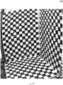
- Fig. 1A shows an illustration 100 of an example of input data, i.e. an input image. It can be seen how big distortion appears in the picture.
- the image shows a checkerboard.
- Fig. 1B shows an illustration 150 of a further example of input data. It can be seen that checkerboards may be provided in more than one plane.
- Fig. 2 shows an illustration 200 of saddle point examples.
- the pixel values are shown over the pixel coordinates.
- the bottom portion shows the image, and the saddle point is at the crossing between the borders between dark areas and light areas.
- the accuracy of finding saddle points may have critical impact on the quality of camera calibration. It may moreover be desired to detect all the saddle points, since not detecting a saddle point may lead to serious problems in the later stages of the calibration procedure (related to problems with matching the saddle points and their predicted location).
- a method of non-maximum suppression may be provided which may increase recall of saddle points by a neural network.
- a non-maximum suppression (NMS) method may ensure that not more than one pixel (or one location, which may be of sub-pixel resolution) is identified as a maximum, even in an image it may appear that a plurality of pixels take a maximum value.
- a standard NMS method may require matching "all with all", which may lead to a O(n 2 ) time complexity, wherein n is the width (or the height) of the image.
- O(n) time complexity may be achieved.
- use vectorization techniques may be used to gain even more speed.
- the calculation on grid structure with independent cells may be easily ported to a GPU (graphics processing unit). This may mean that while the main method (which may be referred to as core) may be running on the GPU, the NMS may also be executed on the GPU without sending data back to the CPU (central processing unit). Exchanging data between CPU and GPU may be time consuming. According to various embodiments, the transmission volume between the CPU and the GPU may be minimized.
- this problem may be overcome by passing the image through the neural network several times. Each time of passing the image through the neural network, the frame may be positioned differently so that the upper left corner of the photo (or image) is shifted from its original position.
- This method may cause the saddle points that were close to the border of the cells to be moved away from the border.
- this approach may require the use of the non-maximum suppressive method (NMS), as most saddle points may be repeatedly detected.
- NMS methods are computationally time-consuming.
- this problem may be overcome by using the grid structure to leverage the speed of the method execution.
- Outputs from different runs, which are with different offsets to each other, may be aligned so that they return values in one reference system. Consequently, for each cell, the final location of the saddle point position in the cell may be independently calculated in parallel using a weighted average, where the weight is determined by the probability of the point's existence.
- Fig. 3 shows an illustration 300 of input data shifting according to various embodiments.
- An input image may for example be divided into a plurality of cells, for example four cells 302, 304, 306, 308.
- the first cell 302 may be the left upper corner cell.
- Detection of saddle points may be carried out for a plurality of shifted images (or shifted cells).
- shifts 310 may be applied, so as to generate a plurality of shifted cells 312 corresponding to the first cell 302.
- Fig. 3B shows an illustration 350 of the alignment according to various embodiments. The alignment process will be illustrated by examining how a saddle point is moved during the alignment.
- the saddle point lies in one of the four subregions, and the point 354 after alignment may be in the same region or in a different region: If the point is inside region 1, then after alignment it may be moved to cell 1'. The position in cell 1' after alignment may be calculated based on the given offset (but in opposite directions). The same may apply to the subregions 2 and 3. For subregion 4, the detected point may still be in the same cell (the lower-right cell), and only the position may be affected by the offset.
- the saddle points may be stretched, so that their sizes may be bigger than the cell size. In such case, when the center of the saddle point is far from the center of the cell, it may be difficult for the saddle point detector to produce a correct output. While commonly used methods may miss saddle points, the method according to various embodiments may properly detect all saddle points.
- the method according to various embodiments may be fast and may improve recall from 98% to 99.9% (with a decreased the number of missed saddle points over 20 times).
- Ground truth (GT) data may be created in a semi-automatic way.
- the results obtained from a "standard detector” may be manually corrected. False positive detections may be removed and missing detections may be added.
- a problem may be that it may be hard to judge where exactly a saddle point is located.
- Creating a ground truth, a saddle point position may only be estimated within +-1px accuracy.
- the prediction may be treated as a true positive (TP) when it is less than two pixels from the GT. In this case, recall may be defined as: #TP/(#all GT on image). It will be understood that the # symbol stands for "number of".
- the locations of saddle points may be used in camera intrinsic calibration. Thus, two sets of detected saddle points on the same image may be compared by checking how well the camera was calibrated (in other words, for which set of saddle points the residual of the camera calibration (model optimization) is smaller).
- Fig. 4 shows a flow diagram 400 illustrating a method for determining pre-determined points in an input image according to various embodiments.
- a plurality of shifts may be applied to the input image to obtain a plurality of shifted images.
- pre-determined points may be detected in each of the shifted images.
- the detected pre-determined points may be re-shifted.
- the pre-determined points may be determined based on the re-shifted detected pre-determined points.
- detecting the pre-determined points may include or may be determining coordinates.
- the re-shifting may include or may be shifting the coordinates to a coordinate system of the input image.
- detecting the pre-determined points may include or may be determining probabilities.
- determining the pre-determined points based on the re-shifted detected pre-determined points may include or may be accumulating the probabilities of the re-shifted detected pre-determined points.
- the input image may be divided into a plurality of cells.
- the shifted images may be shifted by at least one of at least substantially 1% of a size of the cell, or by at least one of at least substantially 2% of the size of the cell, or by at least one of at least substantially 5% of the size of the cell, or by at least one of at least substantially 10% of the size of the cell.
- the image may include or may show a checkerboard.
- the pre-determined points may include or may be saddle points of the checkerboard.
- saddle points may be crossings of black-white borders of the checkerboard.
- the pre-determined points in each of the shifted images may be determined using a machine learning method.
- the machine learning method may include or may be an artificial neural network.
Landscapes
- Engineering & Computer Science (AREA)
- Physics & Mathematics (AREA)
- Theoretical Computer Science (AREA)
- General Physics & Mathematics (AREA)
- Computer Vision & Pattern Recognition (AREA)
- Computational Linguistics (AREA)
- Evolutionary Computation (AREA)
- Artificial Intelligence (AREA)
- Biomedical Technology (AREA)
- Biophysics (AREA)
- Health & Medical Sciences (AREA)
- Data Mining & Analysis (AREA)
- Life Sciences & Earth Sciences (AREA)
- General Health & Medical Sciences (AREA)
- Molecular Biology (AREA)
- Computing Systems (AREA)
- General Engineering & Computer Science (AREA)
- Mathematical Physics (AREA)
- Software Systems (AREA)
- Image Analysis (AREA)
- Image Processing (AREA)
Abstract
Description
- The present disclosure relates to methods and systems for determining pre-determined points in an input image.
- Digital imaging devices, such as digital cameras, are used in automotive applications for a variety of tasks. However, it may be required to properly calibrate the digital imaging device.
- Accordingly, there is a need to provide efficient and reliable methods for camera calibration.
- The present disclosure provides a computer implemented method, a computer system and a non-transitory computer readable medium according to the independent claims. Embodiments are given in the subclaims, the description and the drawings.
- In one aspect, the present disclosure is directed at a computer implemented method for determining pre-determined points in an input image, the method comprising the following steps performed (in other words: carried out) by computer hardware components: applying a plurality of shifts to the input image to obtain a plurality of shifted images; detecting pre-determined points in each of the shifted images; re-shifting the detected pre-determined points; and determining the pre-determined points based on the re-shifted detected pre-determined points.
- In other words, detection may be carried out on shifted images, and the detections may be shifted back (or re-shifted) to the original coordinates, so that the pre-determined points are determined based on the re-shifted detections.
- One of the shifts may be zero, so that the one shifted image may be original image.
- According to an embodiment, detecting the pre-determined points comprises determining coordinates (of the pre-determined points in the shifted images).
- According to an embodiment, the re-shifting comprises shifting the coordinates to a coordinate system of the input image.
- According to an embodiment, detecting the pre-determined points comprises determining probabilities (of a pre-determined point being present at the respective determined coordinates).
- According to an embodiment, determining the pre-determined points based on the re-shifted detected pre-determined points comprises accumulating the probabilities of the re-shifted detected pre-determined points.
- According to an embodiment, the input image is divided into a plurality of cells. Each cell may be a rectangular subportion of the input image. All cells may have identical size, or they may have different sizes. The cells may be overlapping or non-overlapping.
- According to an embodiment, the shifted images are shifted by at least one of at least substantially 1% of a size of the cell, or by at least one of at least substantially 2% of the size of the cell, or by at least one of at least substantially 5% of the size of the cell, or by at least one of at least substantially 10% of the size of the cell.
- For example, the cell size may be 8x8 (in other words: 8 pixels wide, 8 pixels high). The shifts may be an input parameter to the method. The shift may be an integer number (positive or negative) and the absolute value of the shift may be less than the cell size. The method may be executed in parallel, so that several shifts may be set at the same time; for example, the shifts may be selected from a list consisting of: [-6, -4, -2, 0, 2, 4, 6], and the outcome from all the shifts may be merged and utilized at this same time.
- The shift may be carried out in two components, for example vertically and horizontally. For example, the length of the vertical shift may be identical to the length of the horizontal shift (so that a diagonal shift may be provided).
- According to an embodiment, the image comprises (in other words: shows; in other words: includes) a checkerboard.
- According to an embodiment, the pre-determined points comprise saddle points of the checkerboard.
- According to an embodiment, saddle points are crossings of black-white borders of the checkerboard.
- According to an embodiment, the pre-determined points in each of the shifted images are determined using a machine learning method.
- According to an embodiment, the machine learning method comprises an artificial neural network.
- In another aspect, the present disclosure is directed at a computer system, said computer system comprising a plurality of computer hardware components configured to carry out several or all steps of the computer implemented method described herein.
- The computer system may comprise a plurality of computer hardware components (for example a processor, for example processing unit or processing network, at least one memory, for example memory unit or memory network, and at least one non-transitory data storage). It will be understood that further computer hardware components may be provided and used for carrying out steps of the computer implemented method in the computer system. The non-transitory data storage and/or the memory unit may comprise a computer program for instructing the computer to perform several or all steps or aspects of the computer implemented method described herein, for example using the processing unit and the at least one memory unit.
- According to an embodiment, the computer system further comprises a camera configured to acquire the image.
- In another aspect, the present disclosure is directed at a non-transitory computer readable medium comprising instructions for carrying out several or all steps or aspects of the computer implemented method described herein. The computer readable medium may be configured as: an optical medium, such as a compact disc (CD) or a digital versatile disk (DVD); a magnetic medium, such as a hard disk drive (HDD); a solid state drive (SSD); a read only memory (ROM), such as a flash memory; or the like. Furthermore, the computer readable medium may be configured as a data storage that is accessible via a data connection, such as an internet connection. The computer readable medium may, for example, be an online data repository or a cloud storage.
- The present disclosure is also directed at a computer program for instructing a computer to perform several or all steps or aspects of the computer implemented method described herein.
- With the methods and devices as described herein, a technique of using machine learning to identify saddle points in camera calibration patterns may be provided.
- Exemplary embodiments and functions of the present disclosure are described herein in conjunction with the following drawings, showing schematically:
- Fig. 1A
- an illustration of an example of input data;
- Fig. 1B
- an illustration of a further example of input data;
- Fig. 2
- an illustration of saddle point examples;
- Fig. 3A
- an illustration of input data shifting according to various embodiments;
- Fig. 3B
- an illustration of the alignment according to various embodiments; and
- Fig. 4
- a flow diagram illustrating a method for determining pre-determined points in an input image according to various embodiments.
- According to various embodiments, a non maximum suppression method for saddle points detectors may be provided.
- Saddle points on a picture (or image) may be one of the most characteristic features that can be extracted from the picture.
- Saddle points may be widely used for intrinsic calibration of a camera, for extrinsic calibration of camera, and/ or for matching characteristic points.
-
Fig. 1A shows anillustration 100 of an example of input data, i.e. an input image. It can be seen how big distortion appears in the picture. The image shows a checkerboard. -
Fig. 1B shows anillustration 150 of a further example of input data. It can be seen that checkerboards may be provided in more than one plane. -
Fig. 2 shows anillustration 200 of saddle point examples. In the top portion ofFig. 2 , the pixel values are shown over the pixel coordinates. The bottom portion shows the image, and the saddle point is at the crossing between the borders between dark areas and light areas. - The accuracy of finding saddle points may have critical impact on the quality of camera calibration. It may moreover be desired to detect all the saddle points, since not detecting a saddle point may lead to serious problems in the later stages of the calibration procedure (related to problems with matching the saddle points and their predicted location).
- In a method relying on fixed size regions of interest to detect and locate saddle points, problems may arise when a saddle point is located on the border between two or more regions of interest. Such a location of a saddle point frequently leads to a situation in which the particular saddle point is associated with neither of the regions of interest and consequently is not detected. According to various embodiments, the recall of the saddle points located on the borders between regions of interest may be increased.
- According to various embodiments, a method of non-maximum suppression may be provided which may increase recall of saddle points by a neural network. A non-maximum suppression (NMS) method may ensure that not more than one pixel (or one location, which may be of sub-pixel resolution) is identified as a maximum, even in an image it may appear that a plurality of pixels take a maximum value.
- A standard NMS method may require matching "all with all", which may lead to a O(n2) time complexity, wherein n is the width (or the height) of the image. In contrast thereto, according to various embodiments, by leveraging the grid structure, an O(n) time complexity may be achieved.
- According to various embodiments, use vectorization techniques (SIMD (Single instruction, multiple data) instructions) may be used to gain even more speed. In addition, the calculation on grid structure with independent cells may be easily ported to a GPU (graphics processing unit). This may mean that while the main method (which may be referred to as core) may be running on the GPU, the NMS may also be executed on the GPU without sending data back to the CPU (central processing unit). Exchanging data between CPU and GPU may be time consuming. According to various embodiments, the transmission volume between the CPU and the GPU may be minimized.
- When a saddle point appears very close to the edge or corner of the cell it is frequently not detected. According to various embodiments, this problem may be overcome by passing the image through the neural network several times. Each time of passing the image through the neural network, the frame may be positioned differently so that the upper left corner of the photo (or image) is shifted from its original position.
- This method may cause the saddle points that were close to the border of the cells to be moved away from the border. However, this approach may require the use of the non-maximum suppressive method (NMS), as most saddle points may be repeatedly detected. However, NMS methods are computationally time-consuming.
- According to various embodiments, this problem may be overcome by using the grid structure to leverage the speed of the method execution. Outputs from different runs, which are with different offsets to each other, may be aligned so that they return values in one reference system. Consequently, for each cell, the final location of the saddle point position in the cell may be independently calculated in parallel using a weighted average, where the weight is determined by the probability of the point's existence.
-
Fig. 3 shows anillustration 300 of input data shifting according to various embodiments. An input image may for example be divided into a plurality of cells, for example fourcells first cell 302 may be the left upper corner cell. Detection of saddle points may be carried out for a plurality of shifted images (or shifted cells). For example, for thefirst cell 302, shifts 310 may be applied, so as to generate a plurality of shiftedcells 312 corresponding to thefirst cell 302. -
Fig. 3B shows anillustration 350 of the alignment according to various embodiments. The alignment process will be illustrated by examining how a saddle point is moved during the alignment. - Let the (detected)
saddle point 352 be located in the lower-right cell (the one divided in the subregions denoted 1,2,3 and 4). Let the shift be equal to the offset shown inFig. 3B . - The saddle point lies in one of the four subregions, and the
point 354 after alignment may be in the same region or in a different region:
If the point is insideregion 1, then after alignment it may be moved to cell 1'. The position in cell 1' after alignment may be calculated based on the given offset (but in opposite directions). The same may apply to thesubregions subregion 4, the detected point may still be in the same cell (the lower-right cell), and only the position may be affected by the offset. - In highly distorted regions of an image, the saddle points may be stretched, so that their sizes may be bigger than the cell size. In such case, when the center of the saddle point is far from the center of the cell, it may be difficult for the saddle point detector to produce a correct output. While commonly used methods may miss saddle points, the method according to various embodiments may properly detect all saddle points.
- The method according to various embodiments may be fast and may improve recall from 98% to 99.9% (with a decreased the number of missed saddle points over 20 times).
- Ground truth (GT) data may be created in a semi-automatic way. The results obtained from a "standard detector" may be manually corrected. False positive detections may be removed and missing detections may be added. A problem may be that it may be hard to judge where exactly a saddle point is located. Creating a ground truth, a saddle point position may only be estimated within +-1px accuracy. The prediction may be treated as a true positive (TP) when it is less than two pixels from the GT. In this case, recall may be defined as: #TP/(#all GT on image). It will be understood that the # symbol stands for "number of".
- As described above, it may be hard to evaluate "location error" of predictions. The locations of saddle points may be used in camera intrinsic calibration. Thus, two sets of detected saddle points on the same image may be compared by checking how well the camera was calibrated (in other words, for which set of saddle points the residual of the camera calibration (model optimization) is smaller).
-
Fig. 4 shows a flow diagram 400 illustrating a method for determining pre-determined points in an input image according to various embodiments. At 402, a plurality of shifts may be applied to the input image to obtain a plurality of shifted images. At 404, pre-determined points may be detected in each of the shifted images. At 406, the detected pre-determined points may be re-shifted. At 408, the pre-determined points may be determined based on the re-shifted detected pre-determined points. - According to various embodiments, detecting the pre-determined points may include or may be determining coordinates.
- According to various embodiments, the re-shifting may include or may be shifting the coordinates to a coordinate system of the input image.
- According to various embodiments, detecting the pre-determined points may include or may be determining probabilities.
- According to various embodiments, determining the pre-determined points based on the re-shifted detected pre-determined points may include or may be accumulating the probabilities of the re-shifted detected pre-determined points.
- According to various embodiments, the input image may be divided into a plurality of cells.
- According to various embodiments, the shifted images may be shifted by at least one of at least substantially 1% of a size of the cell, or by at least one of at least substantially 2% of the size of the cell, or by at least one of at least substantially 5% of the size of the cell, or by at least one of at least substantially 10% of the size of the cell.
- According to various embodiments, the image may include or may show a checkerboard.
- According to various embodiments, the pre-determined points may include or may be saddle points of the checkerboard.
- According to various embodiments, saddle points may be crossings of black-white borders of the checkerboard.
- According to various embodiments, the pre-determined points in each of the shifted images may be determined using a machine learning method.
- According to various embodiments, the machine learning method may include or may be an artificial neural network.
- Each of the
steps -
- 100
- illustration of an example of input data
- 150
- illustration of a further example of input data
- 200
- illustration of saddle point examples
- 300
- illustration of input data shifting according to various embodiments
- 302
- cell
- 304
- cell
- 306
- cell
- 308
- cell
- 310
- shifts
- 312
- plurality of shifted cells
- 350
- illustration of the alignment according to various embodiments
- 352
- detected point
- 354
- point after alignment
- 400
- flow diagram illustrating a method for determining pre-determined points in an input image according to various embodiments
- 402
- step of applying a plurality of shifts to the input image to obtain a plurality of shifted images
- 404
- step of detecting pre-determined points in each of the shifted images
- 406
- step of re-shifting the detected pre-determined points
- 408
- step of determining the pre-determined points based on the re-shifted detected pre-determined points
Claims (15)
- Computer implemented method for determining pre-determined points in an input image,
the method comprising the following steps carried out by computer hardware components:- applying (402) a plurality of shifts to the input image to obtain a plurality of shifted images;- detecting (404) pre-determined points in each of the shifted images;- re-shifting (406) the detected pre-determined points; and- determining (408) the pre-determined points based on the re-shifted detected pre-determined points. - The computer implemented method of claim 1,
wherein detecting the pre-determined points comprises determining coordinates. - The computer implemented method of claim 2,
wherein the re-shifting comprises shifting the coordinates to a coordinate system of the input image. - The computer implemented method of at least one of claims 1 to 3,
wherein detecting the pre-determined points comprises determining probabilities. - The computer implemented method of at least one of claims 1 to 4,
wherein determining the pre-determined points based on the re-shifted detected pre-determined points comprises accumulating the probabilities of the re-shifted detected pre-determined points. - The computer implemented method of at least one of claims 1 to 5,
wherein the input image is divided into a plurality of cells. - The computer implemented method of at least one of claims 1 to 6,
wherein the shifted images are shifted by at least one of at least substantially 1% of a size of the cell, or by at least one of at least substantially 2% of the size of the cell, or by at least one of at least substantially 5% of the size of the cell, or by at least one of at least substantially 10% of the size of the cell. - The computer implemented method of at least one of claims 1 to 7,
wherein the image comprises a checkerboard. - The computer implemented method of claim 8,
wherein the pre-determined points comprise saddle points of the checkerboard. - The computer implemented method of claim 9,
wherein saddle points are crossings of black-white borders of the checkerboard. - The computer implemented method of at least one of claims 1 to 10,
wherein the pre-determined points in each of the shifted images are determined using a machine learning method. - The computer implemented method of at least one of claims 1 to 11, wherein the machine learning method comprises an artificial neural network.
- Computer system, the computer system comprising a plurality of computer hardware components configured to carry out steps of the computer implemented method of at least one of claims 1 to 12.
- The computer system of claim 13, further comprising:
a camera configured to acquire the image. - Non-transitory computer readable medium comprising instructions for carrying out the computer implemented method of at least one of claims 1 to 12.
Priority Applications (3)
| Application Number | Priority Date | Filing Date | Title |
|---|---|---|---|
| EP21168656.3A EP4075384B1 (en) | 2021-04-15 | 2021-04-15 | Methods and systems for determining pre-determined points in an input image |
| CN202210382510.4A CN115222811A (en) | 2021-04-15 | 2022-04-13 | Method and system for determining predetermined points in an input image |
| US17/659,054 US12430800B2 (en) | 2021-04-15 | 2022-04-13 | Methods and systems for determining pre-determined points in an input image |
Applications Claiming Priority (1)
| Application Number | Priority Date | Filing Date | Title |
|---|---|---|---|
| EP21168656.3A EP4075384B1 (en) | 2021-04-15 | 2021-04-15 | Methods and systems for determining pre-determined points in an input image |
Publications (2)
| Publication Number | Publication Date |
|---|---|
| EP4075384A1 true EP4075384A1 (en) | 2022-10-19 |
| EP4075384B1 EP4075384B1 (en) | 2025-08-13 |
Family
ID=75539220
Family Applications (1)
| Application Number | Title | Priority Date | Filing Date |
|---|---|---|---|
| EP21168656.3A Active EP4075384B1 (en) | 2021-04-15 | 2021-04-15 | Methods and systems for determining pre-determined points in an input image |
Country Status (3)
| Country | Link |
|---|---|
| US (1) | US12430800B2 (en) |
| EP (1) | EP4075384B1 (en) |
| CN (1) | CN115222811A (en) |
Families Citing this family (1)
| Publication number | Priority date | Publication date | Assignee | Title |
|---|---|---|---|---|
| EP4075327A1 (en) | 2021-04-15 | 2022-10-19 | Aptiv Technologies Limited | Methods and systems for training a machine learning method for determining pre-determined points in an image |
Citations (2)
| Publication number | Priority date | Publication date | Assignee | Title |
|---|---|---|---|---|
| CN111105466A (en) * | 2019-12-04 | 2020-05-05 | 南京安科医疗科技有限公司 | Calibration method of camera in CT system |
| CN111640157A (en) * | 2020-05-28 | 2020-09-08 | 华中科技大学 | A Neural Network-Based Checkerboard Corner Detection Method and Its Application |
Family Cites Families (4)
| Publication number | Priority date | Publication date | Assignee | Title |
|---|---|---|---|---|
| US9064315B2 (en) * | 2011-09-28 | 2015-06-23 | The United States Of America As Represented By The Secretary Of The Army | System and processor implemented method for improved image quality and enhancement |
| EP3094076A1 (en) * | 2015-05-13 | 2016-11-16 | Thomson Licensing | Method for obtaining a refocused image from a 4D raw light field data using a shift correction parameter |
| WO2020230891A1 (en) * | 2019-05-15 | 2020-11-19 | 株式会社Nttドコモ | Image processing device |
| EP4075327A1 (en) | 2021-04-15 | 2022-10-19 | Aptiv Technologies Limited | Methods and systems for training a machine learning method for determining pre-determined points in an image |
-
2021
- 2021-04-15 EP EP21168656.3A patent/EP4075384B1/en active Active
-
2022
- 2022-04-13 CN CN202210382510.4A patent/CN115222811A/en active Pending
- 2022-04-13 US US17/659,054 patent/US12430800B2/en active Active
Patent Citations (2)
| Publication number | Priority date | Publication date | Assignee | Title |
|---|---|---|---|---|
| CN111105466A (en) * | 2019-12-04 | 2020-05-05 | 南京安科医疗科技有限公司 | Calibration method of camera in CT system |
| CN111640157A (en) * | 2020-05-28 | 2020-09-08 | 华中科技大学 | A Neural Network-Based Checkerboard Corner Detection Method and Its Application |
Non-Patent Citations (1)
| Title |
|---|
| YANG JIACHEN ET AL: "Precise Measurement of Position and Attitude Based on Convolutional Neural Network and Visual Correspondence Relationship", IEEE TRANSACTIONS ON NEURAL NETWORKS AND LEARNING SYSTEMS, IEEE, PISCATAWAY, NJ, USA, vol. 31, no. 6, 1 June 2020 (2020-06-01), pages 2030 - 2041, XP011791105, ISSN: 2162-237X, [retrieved on 20200601], DOI: 10.1109/TNNLS.2019.2927719 * |
Also Published As
| Publication number | Publication date |
|---|---|
| US20220335651A1 (en) | 2022-10-20 |
| CN115222811A (en) | 2022-10-21 |
| EP4075384B1 (en) | 2025-08-13 |
| US12430800B2 (en) | 2025-09-30 |
Similar Documents
| Publication | Publication Date | Title |
|---|---|---|
| CN110189285B (en) | Method and device for fusion of multi-frame images | |
| US10187546B2 (en) | Method and device for correcting document image captured by image pick-up device | |
| CN111340749B (en) | Image quality detection method, device, equipment and storage medium | |
| US10748023B2 (en) | Region-of-interest detection apparatus, region-of-interest detection method, and recording medium | |
| CN111062984B (en) | Method, device, equipment and storage medium for measuring area of video image area | |
| US20190370974A1 (en) | Information processing apparatus, robot system, information processing method, and program | |
| CN115533902B (en) | A depalletizing method, device, electronic equipment and system based on visual guidance | |
| CN107085843A (en) | System and method for estimating the modulation transfer function in optical system | |
| US12430800B2 (en) | Methods and systems for determining pre-determined points in an input image | |
| US20220335650A1 (en) | Methods and Systems for Training a Machine Learning Method for Determining Pre-Determined Points in an Image | |
| CN114120343A (en) | Certificate image quality evaluation method and terminal | |
| WO2022246643A1 (en) | Image acquisition method and apparatus, and storage medium | |
| CN113870262B (en) | Printed circuit board classification method and device based on image processing and storage medium | |
| CN116309055A (en) | Image processing method, device, electronic device and storage medium | |
| CN117953247B (en) | Single target template matching method, electronic device and storage medium | |
| CN112734721A (en) | Optical axis deflection angle detection method, device, equipment and medium | |
| TWI800814B (en) | Image splicing method | |
| CN120752667A (en) | Image inspection device and image processing method | |
| CN113160060B (en) | Image processing method, device, equipment, and storage medium | |
| CN114998283A (en) | Lens blocking object detection method and device | |
| CN113469969A (en) | Image generation method, image generation device, detection device, and readable storage medium | |
| CN119232922B (en) | Electronic device stable picture detection method, system and image processing system | |
| CN115222586B (en) | Image stitching methods | |
| CN119963660B (en) | External parameter calibration method, device and computer program product for photographing device | |
| CN115866241B (en) | Method, device, medium and equipment for detecting PD lens shading correction effect |
Legal Events
| Date | Code | Title | Description |
|---|---|---|---|
| PUAI | Public reference made under article 153(3) epc to a published international application that has entered the european phase |
Free format text: ORIGINAL CODE: 0009012 |
|
| STAA | Information on the status of an ep patent application or granted ep patent |
Free format text: STATUS: THE APPLICATION HAS BEEN PUBLISHED |
|
| AK | Designated contracting states |
Kind code of ref document: A1 Designated state(s): AL AT BE BG CH CY CZ DE DK EE ES FI FR GB GR HR HU IE IS IT LI LT LU LV MC MK MT NL NO PL PT RO RS SE SI SK SM TR |
|
| RAP3 | Party data changed (applicant data changed or rights of an application transferred) |
Owner name: APTIV TECHNOLOGIES LIMITED |
|
| STAA | Information on the status of an ep patent application or granted ep patent |
Free format text: STATUS: REQUEST FOR EXAMINATION WAS MADE |
|
| 17P | Request for examination filed |
Effective date: 20230419 |
|
| RBV | Designated contracting states (corrected) |
Designated state(s): AL AT BE BG CH CY CZ DE DK EE ES FI FR GB GR HR HU IE IS IT LI LT LU LV MC MK MT NL NO PL PT RO RS SE SI SK SM TR |
|
| RAP1 | Party data changed (applicant data changed or rights of an application transferred) |
Owner name: APTIV TECHNOLOGIES AG |
|
| RAP3 | Party data changed (applicant data changed or rights of an application transferred) |
Owner name: APTIV TECHNOLOGIES AG |
|
| GRAP | Despatch of communication of intention to grant a patent |
Free format text: ORIGINAL CODE: EPIDOSNIGR1 |
|
| STAA | Information on the status of an ep patent application or granted ep patent |
Free format text: STATUS: GRANT OF PATENT IS INTENDED |
|
| INTG | Intention to grant announced |
Effective date: 20250303 |
|
| GRAS | Grant fee paid |
Free format text: ORIGINAL CODE: EPIDOSNIGR3 |
|
| GRAA | (expected) grant |
Free format text: ORIGINAL CODE: 0009210 |
|
| STAA | Information on the status of an ep patent application or granted ep patent |
Free format text: STATUS: THE PATENT HAS BEEN GRANTED |
|
| P01 | Opt-out of the competence of the unified patent court (upc) registered |
Free format text: CASE NUMBER: APP_31365/2025 Effective date: 20250630 |
|
| AK | Designated contracting states |
Kind code of ref document: B1 Designated state(s): AL AT BE BG CH CY CZ DE DK EE ES FI FR GB GR HR HU IE IS IT LI LT LU LV MC MK MT NL NO PL PT RO RS SE SI SK SM TR |
|
| REG | Reference to a national code |
Ref country code: GB Ref legal event code: FG4D |
|
| REG | Reference to a national code |
Ref country code: CH Ref legal event code: EP |
|
| REG | Reference to a national code |
Ref country code: DE Ref legal event code: R096 Ref document number: 602021035946 Country of ref document: DE |
|
| REG | Reference to a national code |
Ref country code: IE Ref legal event code: FG4D |
|
| REG | Reference to a national code |
Ref country code: NL Ref legal event code: MP Effective date: 20250813 |
|
| PG25 | Lapsed in a contracting state [announced via postgrant information from national office to epo] |
Ref country code: IS Free format text: LAPSE BECAUSE OF FAILURE TO SUBMIT A TRANSLATION OF THE DESCRIPTION OR TO PAY THE FEE WITHIN THE PRESCRIBED TIME-LIMIT Effective date: 20251213 |
|
| PG25 | Lapsed in a contracting state [announced via postgrant information from national office to epo] |
Ref country code: NO Free format text: LAPSE BECAUSE OF FAILURE TO SUBMIT A TRANSLATION OF THE DESCRIPTION OR TO PAY THE FEE WITHIN THE PRESCRIBED TIME-LIMIT Effective date: 20251113 |
|
| REG | Reference to a national code |
Ref country code: LT Ref legal event code: MG9D |
|
| PG25 | Lapsed in a contracting state [announced via postgrant information from national office to epo] |
Ref country code: PT Free format text: LAPSE BECAUSE OF FAILURE TO SUBMIT A TRANSLATION OF THE DESCRIPTION OR TO PAY THE FEE WITHIN THE PRESCRIBED TIME-LIMIT Effective date: 20251215 |
|
| PG25 | Lapsed in a contracting state [announced via postgrant information from national office to epo] |
Ref country code: FI Free format text: LAPSE BECAUSE OF FAILURE TO SUBMIT A TRANSLATION OF THE DESCRIPTION OR TO PAY THE FEE WITHIN THE PRESCRIBED TIME-LIMIT Effective date: 20250813 |
|
| PG25 | Lapsed in a contracting state [announced via postgrant information from national office to epo] |
Ref country code: HR Free format text: LAPSE BECAUSE OF FAILURE TO SUBMIT A TRANSLATION OF THE DESCRIPTION OR TO PAY THE FEE WITHIN THE PRESCRIBED TIME-LIMIT Effective date: 20250813 Ref country code: NL Free format text: LAPSE BECAUSE OF FAILURE TO SUBMIT A TRANSLATION OF THE DESCRIPTION OR TO PAY THE FEE WITHIN THE PRESCRIBED TIME-LIMIT Effective date: 20250813 |
|
| PG25 | Lapsed in a contracting state [announced via postgrant information from national office to epo] |
Ref country code: GR Free format text: LAPSE BECAUSE OF FAILURE TO SUBMIT A TRANSLATION OF THE DESCRIPTION OR TO PAY THE FEE WITHIN THE PRESCRIBED TIME-LIMIT Effective date: 20251114 |
|
| PG25 | Lapsed in a contracting state [announced via postgrant information from national office to epo] |
Ref country code: SE Free format text: LAPSE BECAUSE OF FAILURE TO SUBMIT A TRANSLATION OF THE DESCRIPTION OR TO PAY THE FEE WITHIN THE PRESCRIBED TIME-LIMIT Effective date: 20250813 |
|
| PG25 | Lapsed in a contracting state [announced via postgrant information from national office to epo] |
Ref country code: LV Free format text: LAPSE BECAUSE OF FAILURE TO SUBMIT A TRANSLATION OF THE DESCRIPTION OR TO PAY THE FEE WITHIN THE PRESCRIBED TIME-LIMIT Effective date: 20250813 |
|
| PG25 | Lapsed in a contracting state [announced via postgrant information from national office to epo] |
Ref country code: PL Free format text: LAPSE BECAUSE OF FAILURE TO SUBMIT A TRANSLATION OF THE DESCRIPTION OR TO PAY THE FEE WITHIN THE PRESCRIBED TIME-LIMIT Effective date: 20250813 Ref country code: BG Free format text: LAPSE BECAUSE OF FAILURE TO SUBMIT A TRANSLATION OF THE DESCRIPTION OR TO PAY THE FEE WITHIN THE PRESCRIBED TIME-LIMIT Effective date: 20250813 |
|
| PG25 | Lapsed in a contracting state [announced via postgrant information from national office to epo] |
Ref country code: RS Free format text: LAPSE BECAUSE OF FAILURE TO SUBMIT A TRANSLATION OF THE DESCRIPTION OR TO PAY THE FEE WITHIN THE PRESCRIBED TIME-LIMIT Effective date: 20251113 |
|
| PG25 | Lapsed in a contracting state [announced via postgrant information from national office to epo] |
Ref country code: ES Free format text: LAPSE BECAUSE OF FAILURE TO SUBMIT A TRANSLATION OF THE DESCRIPTION OR TO PAY THE FEE WITHIN THE PRESCRIBED TIME-LIMIT Effective date: 20250813 |
|
| REG | Reference to a national code |
Ref country code: AT Ref legal event code: MK05 Ref document number: 1825549 Country of ref document: AT Kind code of ref document: T Effective date: 20250813 |
|
| PG25 | Lapsed in a contracting state [announced via postgrant information from national office to epo] |
Ref country code: SM Free format text: LAPSE BECAUSE OF FAILURE TO SUBMIT A TRANSLATION OF THE DESCRIPTION OR TO PAY THE FEE WITHIN THE PRESCRIBED TIME-LIMIT Effective date: 20250813 |
|
| PGFP | Annual fee paid to national office [announced via postgrant information from national office to epo] |
Ref country code: GB Payment date: 20260305 Year of fee payment: 6 |
|
| PG25 | Lapsed in a contracting state [announced via postgrant information from national office to epo] |
Ref country code: DK Free format text: LAPSE BECAUSE OF FAILURE TO SUBMIT A TRANSLATION OF THE DESCRIPTION OR TO PAY THE FEE WITHIN THE PRESCRIBED TIME-LIMIT Effective date: 20250813 |
|
| PG25 | Lapsed in a contracting state [announced via postgrant information from national office to epo] |
Ref country code: AT Free format text: LAPSE BECAUSE OF FAILURE TO SUBMIT A TRANSLATION OF THE DESCRIPTION OR TO PAY THE FEE WITHIN THE PRESCRIBED TIME-LIMIT Effective date: 20250813 |
|
| PG25 | Lapsed in a contracting state [announced via postgrant information from national office to epo] |
Ref country code: IT Free format text: LAPSE BECAUSE OF FAILURE TO SUBMIT A TRANSLATION OF THE DESCRIPTION OR TO PAY THE FEE WITHIN THE PRESCRIBED TIME-LIMIT Effective date: 20250813 |
|
| PGFP | Annual fee paid to national office [announced via postgrant information from national office to epo] |
Ref country code: FR Payment date: 20260303 Year of fee payment: 6 |
|
| PG25 | Lapsed in a contracting state [announced via postgrant information from national office to epo] |
Ref country code: CZ Free format text: LAPSE BECAUSE OF FAILURE TO SUBMIT A TRANSLATION OF THE DESCRIPTION OR TO PAY THE FEE WITHIN THE PRESCRIBED TIME-LIMIT Effective date: 20250813 |
|
| PG25 | Lapsed in a contracting state [announced via postgrant information from national office to epo] |
Ref country code: EE Free format text: LAPSE BECAUSE OF FAILURE TO SUBMIT A TRANSLATION OF THE DESCRIPTION OR TO PAY THE FEE WITHIN THE PRESCRIBED TIME-LIMIT Effective date: 20250813 Ref country code: SK Free format text: LAPSE BECAUSE OF FAILURE TO SUBMIT A TRANSLATION OF THE DESCRIPTION OR TO PAY THE FEE WITHIN THE PRESCRIBED TIME-LIMIT Effective date: 20250813 |